Stainless Steel Pipe System Vic-Press for Schedule 10S …€¦ · · 2018-01-08• Joins ASTM...
20
victaulic.com 18.12 6390 Rev P Updated 05/2018 © 2018 Victaulic Company. All rights reserved. ALWAYS REFER TO ANY NOTIFICATIONS AT THE END OF THIS DOCUMENT REGARDING PRODUCT INSTALLATION, MAINTENANCE OR SUPPORT. The Victaulic ® PFT510 tool is the only press tool approved for use on the Vic-Press™ for Schedule 10S System. 1.0 PRODUCT DESCRIPTION Available Sizes: • ½ – 2"/DN15 – DN50 Maximum Working Pressure: • Accommodates pressures ranging from full vacuum (29.9 in Hg/760 mm Hg) up to 500 psi/3447 kPa • Rated up to 300 psi when used with Schedule 5S pipe • FM Approved to 300 psi/2068 kPa Application: • Joins ASTM A312 Schedule 10S Types 304/304L stainless steel pipe • Recommended on services conveying water, hydrocarbons, water/hydrocarbon mixtures, air (wet/dry/with oil vapors), other gases, vegetable and mineral oils, as well as automotive fluids such as engine oil and transmission fluid within the temperature range of -30°F to +300°F/-34°C to +149°C, depending on service and seal material selected. Pipe Materials: • Standard ASTM A312 Schedule 10S Types 304/304L stainless steel pipe Codes and Requirements: • Support hanger spacing corresponds to ASME B31.1 Power Piping Code, ASME B31.3 Process Piping, and ASME B31.9 Building Services Piping Code • Meets ASME requirements for ANSI Class 150 systems for water, oil, gases and general chemical services • Meets the requirements of ASME B31.1, B31.3 and B31.9 for Schedule 10S systems • Request publications 18.16, 18.17 and 18.18 for details. Stainless Steel Pipe System Vic-Press ™ for Schedule 10S Type 304/304L Stainless Steel 18.12 1 System No. Location Submitted By Date Spec Section Paragraph Approved Date
Transcript of Stainless Steel Pipe System Vic-Press for Schedule 10S …€¦ · · 2018-01-08• Joins ASTM...

victaulic.com 18.12 6390 Rev P Updated 05/2018 © 2018 Victaulic Company. All rights reserved.
ALWAYS REFER TO ANY NOTIFICATIONS AT THE END OF THIS DOCUMENT REGARDING PRODUCT INSTALLATION, MAINTENANCE OR SUPPORT.
The Victaulic® PFT510 tool is the only press tool approved for use on the Vic-Press™ for Schedule 10S System.
1.0 PRODUCT DESCRIPTION
Available Sizes:• ½ – 2"/DN15 – DN50
Maximum Working Pressure:• Accommodates pressures ranging from full vacuum (29.9 in Hg/760 mm Hg) up to 500 psi/3447 kPa
• Rated up to 300 psi when used with Schedule 5S pipe
• FM Approved to 300 psi/2068 kPa
Application:• Joins ASTM A312 Schedule 10S Types 304/304L stainless steel pipe
• Recommended on services conveying water, hydrocarbons, water/hydrocarbon mixtures, air (wet/dry/with oil vapors), other gases, vegetable and mineral oils, as well as automotive fluids such as engine oil and transmission fluid within the temperature range of -30°F to +300°F/-34°C to +149°C, depending on service and seal material selected.
Pipe Materials:• Standard ASTM A312 Schedule 10S Types 304/304L stainless steel pipe
Codes and Requirements:• Support hanger spacing corresponds to ASME B31.1 Power Piping Code, ASME B31.3 Process Piping, and ASME
B31.9 Building Services Piping Code
• Meets ASME requirements for ANSI Class 150 systems for water, oil, gases and general chemical services
• Meets the requirements of ASME B31.1, B31.3 and B31.9 for Schedule 10S systems
• Request publications 18.16, 18.17 and 18.18 for details.
Stainless Steel Pipe SystemVic-Press™ for Schedule 10S Type 304/304L Stainless Steel 18.12
1
System No. Location
Submitted By Date
Spec Section Paragraph
Approved Date

18.12 6390 Rev P Updated 05/2018 © 2018 Victaulic Company. All rights reserved.
victaulic.com
1.1 PRODUCT DESCRIPTION
Vic-Press™ Joining System for Schedule 10S Type 304/304L Stainless Steel Pipe
Dimensional Information• Products in the Vic-Press™ for Schedule 10S system for Type 304/304L stainless steel have unique center-to-
end or end-to-end dimensions which incorporate specific, “takeout” dimensions for easy fabrication calculations.
• Use of threaded products employing special features such as probes, escutcheon cups, etc., should be checked to be certain the thread standard and length of insertion are compatible with fitting dimensions.
• Failure to verify dimensional suitability in advance may result in difficulties in assembly.
P End Type Code
P = Press F = Female Thread M = Male Thread T = Plain End L = Flanged G = Grooved EOB = End of Branch W = Weld Ends
P P
2.0 CERTIFICATION/LISTINGS
NOTE• See publication publication 02.06: Victaulic Potable Water Approvals ANSI/NSF for potable water approvals if applicable.
• For complete information on Maritime approvals, visit https://www.victaulic.com/maritime-approvals/
INSERTION MARKA witness mark made by installer prior to installation allows for visual verification that the pipe has been fully inserted for proper installation.
PRESSED JOINT SEAL POCKETSeal is compressed to provide a leak-free connection for a variety of wet and dry services.
PIPE STOPAn internal pipe stop locates pipe position to ensure positive joining.
HOUSINGPrecision formed stainless steel construction
incorporating the pipe stop and seal.
PRE-LUBRICATED SEAL With patent-pending press detection technology.
POSITIVE MECHANICAL INTERLOCKThe Vic-Press™ PFT510 hand-held tool
engages the entire circumference of the fitting to ensure a secure attachment of pipe to fitting.
2
victaulic.com

18.12 6390 Rev P Updated 05/2018 © 2018 Victaulic Company. All rights reserved.
victaulic.com
3.0 SPECIFICATIONS - MATERIAL
Housing: Made from Type 304L stainless steel.
Threaded Outlets: Made from stainless steel bar or stainless steel pipe conforming to ASTM A312, Type 304L.
Plain End or Grooved End Products: Stainless steel pipe conforming to ASTM A312, Type 304L.
Style P595 Flange Adapter: ANSI Class 150 or AS 2129 Table E, Type 316L raised face one-piece Type 304L stainless steel flange adapter.
Style P565 Van Stone Flange Adapter: ANSI Class 150 or AS 2129 Table E, carbon steel raised face slip on flange with Type 304 stainless steel stub end.
Style P594 Concentric Reducer: Reducer body made from Type 304 stainless steel, press ends made from Type 304L stainless steel.
Seal:
Victaulic Grade “H” HNBR HNBR (Two orange stripes color code). Temperature range -20°F to +210°F/-29°C to +98°C. May be specified for hot petroleum/water mixtures, hyrdocarbons, air with oil vapors, vegetable and mineral oils, engine oil, transmission oil. UL Classified in accordance with ANSI/NSF 61 for cold +73°F/+23°C and hot +180°F/+82°C potable water service and ANSI/NSF 372.
Optional Seal: (specify choice1) Victaulic Grade “E” EPDM
EPDM (Green stripe color code). Temperature range -30°F to +250°F/-34°C to +121°C. May be specified for hot water service, dilute acids, oil-free air, chemical services. UL Classified in accordance with ANSI/NSF 61 for cold +73°F/+23°C and hot +180°F/+82°C potable water service and ANSI/ NSF 372. NOT COMPATIBLE FOR USE WITH PETROLEUM OR STEAM SERVICES.
Victaulic Grade “O” Fluoroelastomer Fluoroelastomer (Blue stripe color code). Temperature range +20°F to + 300°F/–7°C to +149°C. May be specified for many oxidizing acids, petroleum oils, halogenated hydrocarbons, lubricants, hydraulic fluids, organic liquids and air with hydrocarbons. NOT COMPATIBLE FOR USE WITH HOT WATER OR STEAM SERVICES.
Others For alternate gasket selection, reference publication 05.01: Victaulic Seal Selection Guide - Elastomeric Seal Construction.
1 Services listed are General Service Guidelines only. It should be noted that there are services for which these gaskets are not compatible. Reference should always be made to the latest Victaulic Seal Selection Guide for specific gasket service guidelines and for a listing of services which are not compatible.
NOTE• Vic-Press™ for Schedule 10S seals are pre-lubricated to further simplify the installation process. To maintain the integrity of the lubrication, components are
shipped in factory sealed bags and should remain bagged until ready for use. For more information regarding the lubricant used, please refer to publication 05.07.
3
victaulic.com
18.12 6390 Rev P Updated 05/2018 © 2018 Victaulic Company. All rights reserved.
victaulic.com
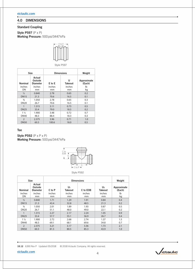
4.0 DIMENSIONS
Standard Coupling
Style P597 (P x P) Working Pressure: 500 psi/3447 kPa
UE to E
Style P597
Size Dimensions Weight
Nominal
Actual Outside Diameter E to E
U Takeout
Approximate (Each)
inches DN
inches mm
inches mm
inches mm
lb kg
1/2 0.840 2.78 0.65 0.2DN15 21.3 70.6 16.5 0.1
3/4 1.050 2.78 0.65 0.3DN20 26.7 70.6 16.5 0.1
1 1.315 3.11 0.73 0.5DN25 33.4 79.0 18.5 0.2
1 1/2 1.900 3.48 0.72 0.7DN40 48.3 88.4 18.3 0.3
2 2.375 3.96 0.71 1.0DN50 60.3 100.6 18.0 0.5
Tee
Style P592 (P x P x P) Working Pressure: 500 psi/3447 kPa
C to EOB
C to PU
1
U2
Style P592
Size Dimensions Weight
Nominal
Actual Outside Diameter C to P
U1 Takeout C to EOB
U2 Takeout
Approximate (Each)
inches DN
inches mm
inches mm
inches mm
inches mm
inches mm
lb kg
1/2 0.840 1.71 1.29 1.91 0.84 0.4DN15 21.3 43.4 32.8 48.5 21.3 0.2
3/4 1.050 2.01 1.89 1.93 0.87 0.5DN20 26.7 51.1 48.0 49.0 22.1 0.2
1 1.315 2.27 2.17 2.24 1.05 0.9DN25 33.4 57.7 55.1 56.9 26.7 0.4
1 1/2 1.900 2.72 2.68 2.74 1.37 1.5DN40 48.3 69.1 68.1 69.6 34.8 0.7
2 2.375 3.21 3.17 3.36 1.73 2.1DN50 60.3 81.5 80.5 85.3 43.9 1.0
4
victaulic.com

18.12 6390 Rev P Updated 05/2018 © 2018 Victaulic Company. All rights reserved.
victaulic.com
4.1 DIMENSIONS
Tee with Reducing Branch
Style P593 (P x P x P) Working Pressure: 500 psi/3447 kPa
Cto
EOB U2
C to PEU
1
Style P593
Size Dimensions Weight
Nominal
Actual Outside
Diameter C to P U1
Takeout C to EOBU2
TakeoutApproximate
(Each)inches
DNinches
mminches
mminches
mminches
mminches
mmlb kg
3/4x
3/4x
1/2 1.050x
1.050x
0.840 2.01 1.89 2.01 0.95 0.5DN20 DN20 DN15 26.7 26.7 21.3 51.1 48.0 51.1 24.1 0.2
1x
1x
1/2 1.315x
1.315x
0.840 2.27 2.17 2.14 1.08 0.8DN25 DN25 DN15 33.4 33.4 21.3 57.7 55.1 54.4 27.4 0.4
3/4 1.050 2.27 2.17 2.07 1.00 0.8DN20 26.7 57.7 55.1 52.6 25.4 0.4
1 1/2x
1 1/2x
1/2 1.900x
1.900x
0.840 2.72 2.69 2.44 1.17 1.2DN40 DN40 DN15 48.3 48.3 21.3 69.1 68.3 62.0 29.7 0.5
3/4 1.050 2.72 2.69 2.36 1.29 1.3DN20 26.7 69.1 68.3 59.9 32.8 0.6
1 1.315 2.72 2.69 2.53 1.34 1.4DN25 33.4 69.1 68.3 64.3 34.0 0.6
2x
2x
1/2 2.375x
2.375x
0.840 3.21 3.16 2.67 1.61 1.7DN50 DN50 DN15 60.3 60.3 21.3 81.5 80.3 67.8 40.9 0.8
3/4 1.050 3.21 3.16 2.60 1.53 1.7DN20 26.7 81.5 80.3 66.0 38.9 0.8
1 1.315 3.21 3.16 2.77 1.58 1.8DN25 33.4 81.5 80.3 70.4 40.1 0.8
1 1/2 1.900 3.21 3.16 2.98 1.60 2.0DN40 48.3 81.5 80.3 75.7 40.6 0.9
5
victaulic.com

18.12 6390 Rev P Updated 05/2018 © 2018 Victaulic Company. All rights reserved.
victaulic.com
4.2 DIMENSIONS
Tee with Threaded Branch2
Style P588 (P x P x F) Working Pressure: 500 psi/3447 kPa
Cto
EOBU
2
C to PU
1
*
Style P588*Length of effective thread
Size Dimensions Weight
Nominal
Actual Outside
Diameter C to P U1
Takeout C to EOBU2
TakeoutApproximate
(Each)inches
DNinches
mminches
mminches
mminches
mminches
mmlb kg
1/2x
1/2x
1/2 0.840x
0.840x
0.840 1.71 1.29 1.46 0.93 0.4DN15 DN15 DN15 21.3 21.3 21.3 43.4 32.8 37.1 23.6 0.2
3/4x
3/4x
1/2 1.050x
1.050 0.840 2.01 1.89 1.57 1.04 0.5DN20 DN20 DN15 26.7 26.7 21.3 51.1 48.0 39.9 26.4 0.2
3/4 1.050 2.01 1.89 1.56 1.02 0.6DN20 26.7 51.1 48.0 39.6 25.9 0.3
1x
1x
1/2 1.315x
1.315x
0.840 2.27 2.17 1.70 1.17 0.9DN25 DN25 DN15 33.4 33.4 21.3 57.7 55.1 43.2 29.7 0.4
3/4 1.050 2.27 2.17 1.70 1.15 0.9DN20 26.7 57.7 55.1 43.2 29.2 0.4
1 1.315 2.27 2.17 1.83 1.15 1.1DN25 33.4 57.7 55.1 46.5 29.2 0.5
1 1/2x
1 1/2x
1/2 1.900x
1.900x
0.840 2.72 2.68 1.99 1.46 1.4DN40 DN40 DN15 48.3 48.3 21.3 69.1 68.1 50.5 37.1 0.6
3/4 1.050 2.72 2.68 1.99 1.44 1.5DN20 26.7 69.1 68.1 50.5 36.6 0.7
1 1.315 2.72 2.68 2.12 1.44 1.5DN25 33.4 69.1 68.1 53.8 36.6 0.7
2x
2x
1/2 2.375x
2.375 0.840 3.21 3.17 2.23 1.70 1.7DN50 DN50 DN15 60.3 60.3 21.3 85.1 80.5 56.6 43.2 0.8
3/4 1.050 3.21 3.17 2.23 1.68 1.7DN20 26.7 85.1 80.5 56.6 42.7 0.8
1 1.315 3.21 3.17 2.36 1.68 2.0DN25 33.4 85.1 80.5 59.9 42.7 0.9
2 Available with British Standard Pipe Threads. Specify BSPT on order.
6
victaulic.com

18.12 6390 Rev P Updated 05/2018 © 2018 Victaulic Company. All rights reserved.
victaulic.com
4.3 DIMENSIONS
Elbows
Style P586 90º Elbow (P × P) Style P542 90º Street Elbow (P x T) Style P591 45º Elbow (P x P) Style P543 45º Street Elbow (P x T) Working Pressure: 500 psi/3447 kPa
C to PU C to T
UCtoP
Style P586 Style P542
SizeStyle P586 90° Elbow
Style P542 90° Street Elbow
NominalActual Outside
Diameter C to PU
TakeoutApprox.
Weight (Each) C to PU
Takeout C to TApprox.
Weight (Each)inches
DN inches
mminches
mminches
mmlb kg
inches mm
inches mm
inches mm
lb kg
1/2 0.840 2.64 1.53 0.3 2.64 1.53 3.04 0.3DN15 21.3 67.1 38.9 0.1 67.1 38.9 77.2 0.1
3/4 1.050 2.95 1.89 0.4 2.95 1.89 3.35 0.4DN20 26.7 74.9 48.0 0.2 74.9 48.0 85.1 0.2
1 1.315 3.52 2.33 0.8 3.52 2.33 4.32 0.7DN25 33.4 89.4 59.2 0.4 89.4 59.2 109.7 0.3
1 1/2 1.900 4.55 3.18 1.4 4.55 3.18 4.55 1.4DN40 48.3 115.6 80.8 0.6 115.6 80.8 115.6 0.6
2 2.375 5.52 3.90 2.0 5.52 3.90 5.52 2.0DN50 60.3 140.2 99.1 0.9 140.2 99.1 140.2 0.9
CtoP
U Cto P
U
C to T
Style P591 Style P543
SizeStyle P591 45° Elbow
Style P543 45° Street Elbow
NominalActual Outside
Diameter C to PU
TakeoutApprox.
Weight (Each) C to PU
Takeout C to TApprox.
Weight (Each)inches
DN inches
mminches
mminches
mmlb kg
inches mm
inches mm
inches mm
lb kg
1/2 0.840 1.89 0.83 0.2 1.89 0.83 1.89 0.2DN15 21.3 48.0 21.1 0.1 48.0 21.1 48.0 0.1
3/4 1.050 2.56 1.50 0.4 2.56 1.50 2.56 0.4DN20 26.7 65.0 38.1 0.2 65.0 38.1 65.0 0.2
1 1.315 3.27 2.09 0.8 3.27 2.09 3.27 0.8DN25 33.4 83.1 53.1 0.4 83.1 63.9 83.1 0.4
1 1/2 1.900 4.96 3.59 1.7 4.96 3.59 4.96 1.7DN40 48.3 126.0 91.2 0.8 126.0 91.2 126.0 0.8
2 2.375 5.84 4.22 2.5 5.84 4.22 5.84 2.5DN50 60.3 148.3 107.2 1.1 148.3 107.2 148.3 1.1
7
victaulic.com

18.12 6390 Rev P Updated 05/2018 © 2018 Victaulic Company. All rights reserved.
victaulic.com
4.4 DIMENSIONS
Male Threaded Adapter2
Style P596 (P x M) Working Pressure: 500 psi/3447kPa
*E to E
IL U
*Length of effective thread Style P596
Size Dimensions Weight
Nominal
Actual Outside
DiameterE to E U
Takeout
IL Insertion Length
Approx. (Each)
inches DN
inches mm
inches mm
inches mm
inches mm
lb kg
1/2x
1/2 0.840x
0.840 3.93 2.32 1.06 0.3DN15 DN15 21.3 21.3 99.8 58.9 26.9 0.1
3/4x
1/2 1.050x
0.840 3.34 1.75 1.06 0.4DN20 DN15 26.7 21.3 84.8 44.5 26.9 0.2
3/4 1.050 3.85 2.22 1.06 0.4DN20 26.7 97.8 56.4 26.9 0.2
1 1.315 3.34 1.60 1.06 0.5DN25 33.4 84.8 40.6 26.9 0.2
1x
3/4 1.315x
1.050 3.50 1.77 1.19 0.5DN25 DN20 33.4 26.7 88.9 45.0 30.2 0.2
1 1.315 4.19 2.32 1.19 0.6DN25 33.4 106.4 58.9 30.2 0.3
1 1/2x
3/4 1.900x
1.050 3.65 1.73 1.38 0.8DN40 DN20 48.3 26.7 92.7 43.9 35.1 0.4
1 1/2 1.900 4.38 2.28 1.38 1.0DN40 48.3 111.3 57.9 35.1 0.5
2x
2 2.375x
2.375 4.86 2.46 1.63 1.4DN50 DN50 60.3 60.3 123.4 62.5 41.4 0.6 2 Available with British Standard Pipe Threads. Specify BSPT on order.
End Cap
Style P540 Working Pressure: 500 psi/3447 kPa
InsertionMark
Cut-off Line for future system expansion
IL CL
E to E
Style P540
Size Dimensions Weight
Nominal
Actual Outside
Diameter E to E
IL Insertion Length CL
Approx. (Each)
inches DN
inches mm
inches mm
inches mm
Cut-off Line
lb kg
1/2 0.840 4.00 1.06 0.5 0.24DN15 21.3 101.60 26.9 12.7 0.11
3/4 1.050 4.00 1.06 0.5 0.30DN20 26.7 101.60 26.9 12.7 0.14
1 1.315 4.38 1.19 0.5 0.54DN25 33.4 111.25 30.2 12.7 0.24
1 1/2 1.900 4.75 1.38 0.5 0.87DN40 48.3 120.65 35.1 12.7 0.39
2 2.375 5.25 1.63 0.5 1.22DN50 60.3 133.35 41.4 12.7 0.55
Female Threaded Adapter2
Style P599 (P x F) Working Pressure: 500 psi/3447 kPa
*E to E
IL U
*Length of effective thread Style P599
Size Dimensions Weight
Nominal
Actual Outside
DiameterE to E U
Takeout
IL Insertion Length
Approx. (Each)
inches DN
inches mm
inches mm
inches mm
inches mm
lb kg
1/2x
1/2 0.840x
0.840 2.39 0.79 1.06 0.3DN15 DN15 21.3 21.3 60.7 20.1 26.9 0.1
3/4x
1/2 1.050x
0.840 2.31 0.71 1.06 0.3DN20 DN15 26.7 21.3 58.7 18.0 26.9 0.1
3/4 1.050 2.31 0.79 1.06 0.4DN20 26.7 58.7 20.1 26.9 0.2
1x
1/2 1.315x
0.840 2.47 0.75 1.19 0.7DN25 DN15 33.4 21.3 62.7 19.1 30.2 0.3
3/4 1.050 2.47 0.73 1.19 0.6DN20 26.7 62.7 18.5 30.2 0.3
1 1.315 2.60 0.88 1.19 0.6DN25 33.4 66.0 22.4 30.2 0.3
1 1/2x
1 1.900x
1.315 2.92 0.91 1.38 1.0DN40 DN25 48.3 33.4 74.2 23.1 35.1 0.5
1 1/4 1.660 2.92 0.86 1.38 0.8DN32 42.4 74.2 21.8 35.1 0.4
1 1/2 1.900 2.92 0.86 1.38 1.0DN40 48.3 74.2 21.8 35.1 0.5
2x
1 1/4 2.375x
1.660 3.57 1.24 1.63 1.1DN50 DN32 60.3 42.4 90.7 31.5 41.4 0.5
x1 1/2 1.900 3.57 1.24 1.63 1.3
DN40 48.3 90.7 31.5 41.4 0.6
x 2 2.375 3.57 1.24 1.63 1.2DN50 60.3 90.7 31.5 41.4 0.5
2 Available with British Standard Pipe Threads. Specify BSPT on order.
8
victaulic.com

18.12 6390 Rev P Updated 05/2018 © 2018 Victaulic Company. All rights reserved.
victaulic.com
4.5 DIMENSIONS
Threaded Union
Style P584 (P x P) Working Pressure: 500 psi/3447 kPa
E to EU
Style P584
Size Dimensions Weight
Nominal
Actual Outside
Diameter E to EU
TakeoutApprox. (Each)
inches DN
inches mm
inches mm
inches mm
lb kg
1/2 0.840 7.50 5.37 3.0DN15 21.3 190.5 136.4 1.4
3/4 1.050 7.37 5.24 3.7DN20 26.7 187.2 133.1 1.7
1 1.315 7.59 5.21 4.3DN25 33.4 192.8 132.3 2.0
1 1/2 1.900 8.36 5.61 6.0DN40 48.3 212.3 142.5 2.7
2 2.375 8.01 4.76 6.8DN50 60.3 203.5 120.9 3.1
Transition Nipple
Style P587 (G × T) Working Pressure: 500 psi/3447 kPa
E to E
InsertionMark
L1
Style P587
Size Dimensions Weight
Nominal
Actual Outside
Diameter E to EL1
MinimumApprox. (Each)
inches DN
inches mm
inches mm
inches mm
lb kg
3/4 1.050 4.00 1.06 0.3DN20 26.7 101.6 26.9 0.1
1 1.315 4.00 1.19 0.5DN25 33.4 101.6 30.2 0.2
1 1/2 1.900 4.00 1.38 0.7DN40 48.3 101.6 35.1 0.3
2 2.375 4.00 1.63 0.9DN50 60.3 101.6 41.4 0.4
Concentric Reducer
Style P594 (P x P) Working Pressure: 500 psi/3447 kPa
UE to E
Style P594
Size Dimensions Weight
Nominal
Actual Outside
Diameter E to EU
TakeoutApprox. (Each)
inches DN
inches mm
inches mm
inches mm
lb kg
3/4x
1/2 1.050x
0.840 4.25 2.13 0.5DN20 DN15 26.7 21.3 108.0 54.1 0.2
1x
1/2 1.315x
0.840 4.92 2.67 0.6DN25 DN15 33.4 21.3 125.0 67.8 0.3
3/4 1.050 4.84 2.59 0.7DN20 26.7 122.9 65.8 0.3
1 1/2x
1/2 1.900x
0.840 5.57 3.13 0.9DN40 DN15 48.3 21.3 141.5 79.5 0.4
3/4 1.050 5.49 3.06 1.0DN20 26.7 139.4 77.7 0.5
1 1.315 5.66 3.09 1.1DN25 33.4 143.8 78.5 0.5
2x
1/2 2.375x
0.840 6.52 3.84 1.2DN50 DN15 60.3 21.3 165.6 97.5 0.5
3/4 1.050 6.44 3.76 1.3DN20 26.7 163.6 95.5 0.6
1 1.315 6.60 3.79 1.4DN25 33.4 167.6 96.3 0.6
1 1/2 1.900 6.75 3.76 1.6DN40 48.3 171.5 95.5 0.7
9
victaulic.com
18.12 6390 Rev P Updated 05/2018 © 2018 Victaulic Company. All rights reserved.
victaulic.com
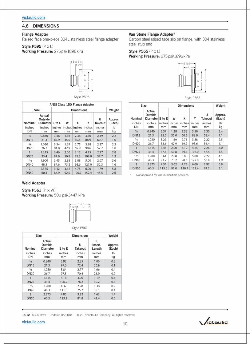
4.6 DIMENSIONS
Flange Adapter Raised face one-piece 304L stainless steel flange adapter
Style P595 (P x L) Working Pressure: 275 psi/1896 kPa
X
E to E
W Y
U
Style P595
ANSI Class 150 Flange Adapter
Size Dimensions Weight
Nominal
Actual Outside
Diameter E to E W X YU
TakeoutApprox. (Each)
inches DN
inches mm
inches mm
inches mm
inches mm
inches mm
inches mm
lb kg
1/2 0.840 3.46 1.38 2.38 3.50 2.39 2.2DN15 21.3 87.9 35.0 60.5 88.9 60.7 1.0
3/4 1.050 3.34 1.69 2.75 3.88 2.27 2.3DN20 26.7 84.8 42.9 69.9 98.6 57.7 1.0
1 1.315 3.46 2.00 3.12 4.25 2.27 2.8DN25 33.4 87.9 50.8 79.3 108.0 57.7 1.3
1 1/2 1.900 3.45 2.88 3.88 5.00 2.07 3.6DN40 48.3 87.6 73.2 98.6 127.0 52.3 1.6
2 2.375 3.42 3.62 4.75 6.00 1.79 5.8DN50 60.3 86.9 92.0 120.7 152.4 45.5 2.6
Weld Adapter
Style P561 (P × W) Working Pressure: 500 psi/3447 kPa
E to EUIL
Style P561
Size Dimensions Weight
Nominal
Actual Outside
Diameter E to EU
Takeout
IL Insert. Length
Approx. (Each)
inches DN
inches mm
inches mm
inches mm
inches mm
lb kg
1/2 0.840 3.92 2.85 1.06 0.3DN15 21.3 99.6 72.4 26.9 0.1
3/4 1.050 3.84 2.77 1.06 0.4DN20 26.7 97.5 70.4 26.9 0.2
1 1.315 4.18 3.00 1.19 0.6DN25 33.4 106.2 76.2 30.2 0.3
1 1/2 1.900 4.37 2.98 1.38 0.9DN40 48.3 111.0 75.7 35.1 0.4
2 2.375 4.85 3.22 1.63 1.4DN50 60.3 123.2 81.8 41.4 0.6
Van Stone Flange Adapter3 Carbon steel raised face slip on flange, with 304 stainless steel stub end
Style P565 (P x L) Working Pressure: 275 psi/1896 kPa
E to EU
XW Y
Style P565
Size Dimensions Weight
Nominal
Actual Outside
Diameter E to E W X YU
TakeoutApprox. (Each)
inches DN
inches mm
inches mm
inches mm
inches mm
inches mm
inches mm
lb kg
1/2 0.840 3.37 1.38 2.38 3.50 2.30 2.4DN15 21.3 85.6 35.0 60.5 88.9 58.4 1.1
3/4 1.050 3.29 1.69 2.75 3.88 2.22 2.5DN20 26.7 83.6 42.9 69.9 98.6 56.4 1.1
1 1.315 3.45 2.00 3.12 4.25 2.26 3.0DN25 33.4 87.6 50.8 79.3 108.0 57.4 1.4
1 1/2 1.900 3.61 2.88 3.88 5.00 2.22 4.1DN40 48.3 91.7 73.2 98.6 127.0 56.4 1.9
2 2.375 4.55 3.62 4.75 6.00 2.92 6.8DN50 60.3 115.6 92.0 120.7 152.4 74.2 3.1
3 Not approved for use in maritime services.
10
victaulic.com

18.12 6390 Rev P Updated 05/2018 © 2018 Victaulic Company. All rights reserved.
victaulic.com
4.7 DIMENSIONS
Vic-Press™ Schedule 10S Type 316 Stainless Steel Ball Valve
Series P5693
Working Pressure: 400 psi/2758 kPa
• Series P569 Vic-Press™ for Schedule 10S System Ball Valves with Type 316 ends feature full stainless steel body and trim, rated for service up to 400 psi/2758 kPa.
• The valves are constructed of rugged Type 316 (CF8M) stainless steel with PTFE seats. The valves feature a blow-out proof stem and self-adjusting floating ball which provides uniform sealing. The full port design minimizes pressure drop for maximum flow efficiency. The three-piece swing-out design permits easy in-line maintenance.
Vic-Press™ for Schedule 10S x Vic-Press™ Schedule 10S (P x P)
B
E
A C
Size Dimensions Weight
NominalActual Outside
DiameterA
End to End B C E
Approximate (Each)
inches DN
inches mm
inches mm
inches mm
inches mm
inches mm
lb kg
1/2 0.840 8.44 2.24 1.06 4.02 1.5DN15 21.3 214.3 56.9 26.9 102.1 0.7
3/4 1.050 8.63 2.64 1.06 4.96 2.4DN20 26.7 219.2 67.0 26.9 126.0 1.1
1 1.315 9.23 2.76 1.19 5.00 3.6DN25 33.4 234.4 70.1 30.2 127.0 1.6
1 1/2 1.900 10.11 3.74 1.38 6.14 6.9DN40 48.3 256.8 95.0 35.1 156.0 3.1
2 2.375 10.46 4.02 1.63 7.52 9.5DN50 60.3 265.7 102.1 41.4 191.0 4.3
3 Not approved for use in maritime services.
NOTE• For dimensions and weights with gear operator contact Victaulic.
Groove x Groove (G x G)
A
B
E
Size Dimensions Weight
NominalActual Outside
DiameterA
End to End B E
Approximate (Each)
inches DN
inches mm
inches mm
inches mm
inches mm
lb kg
3/4 1.050 8.81 2.64 4.96 2.4DN20 26.7 223.8 67.0 126.0 1.1
1 1.315 9.21 2.76 5.00 3.6DN25 33.4 234.0 70.1 127.0 1.6
1 1/2 1.900 11.25 3.74 6.14 6.9DN40 48.3 285.8 95.0 156.0 3.1
2 2.375 12.74 4.02 7.52 9.5DN50 60.3 323.6 102.1 191.0 4.3
3 Not approved for use in maritime services.
NOTE• For dimensions and weights with gear operator contact Victaulic.
11
victaulic.com
18.12 6390 Rev P Updated 05/2018 © 2018 Victaulic Company. All rights reserved.
victaulic.com
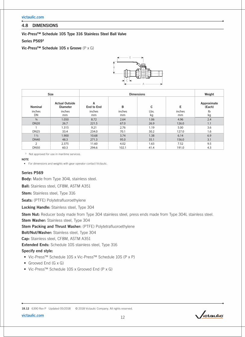
4.8 DIMENSIONS
Vic-Press™ Schedule 10S Type 316 Stainless Steel Ball Valve
Series P5693
Vic-Press™ Schedule 10S x Groove (P x G)
B
E
C A
Size Dimensions Weight
NominalActual Outside
DiameterA
End to End B C E
Approximate (Each)
inches DN
inches mm
inches mm
inches mm
Lbs. kg
inches mm
lb kg
3/4 1.050 8.72 2.64 1.06 4.96 2.4DN20 26.7 221.5 67.0 26.9 126.0 1.1
1 1.315 9.21 2.76 1.19 5.00 3.6DN25 33.4 234.0 70.1 30.2 127.0 1.6
1 1/2 1.900 10.68 3.74 1.38 6.14 6.9DN40 48.3 271.3 95.0 35.1 156.0 3.1
2 2.375 11.60 4.02 1.63 7.52 9.5DN50 60.3 294.6 102.1 41.4 191.0 4.3
3 Not approved for use in maritime services.
NOTE• For dimensions and weights with gear operator contact Victaulic.
Series P569
Body: Made from Type 304L stainless steel.
Ball: Stainless steel, CF8M, ASTM A351
Stem: Stainless steel, Type 316
Seats: (PTFE) Polytetrafluoroethylene
Locking Handle: Stainless steel, Type 304
Stem Nut: Reducer body made from Type 304 stainless steel, press ends made from Type 304L stainless steel.
Stem Washer: Stainless steel, Type 304
Stem Packing and Thrust Washer: (PTFE) Polytetrafluoroethylene
Bolt/Nut/Washer: Stainless steel, Type 304
Cap: Stainless steel, CF8M, ASTM A351
Extended Ends: Schedule 10S stainless steel, Type 316
Specify end style:
• Vic-Press™ Schedule 10S x Vic-Press™ Schedule 10S (P x P)
• Grooved End (G x G)
• Vic-Press™ Schedule 10S x Grooved End (P x G)
12
victaulic.com
18.12 6390 Rev P Updated 05/2018 © 2018 Victaulic Company. All rights reserved.
victaulic.com
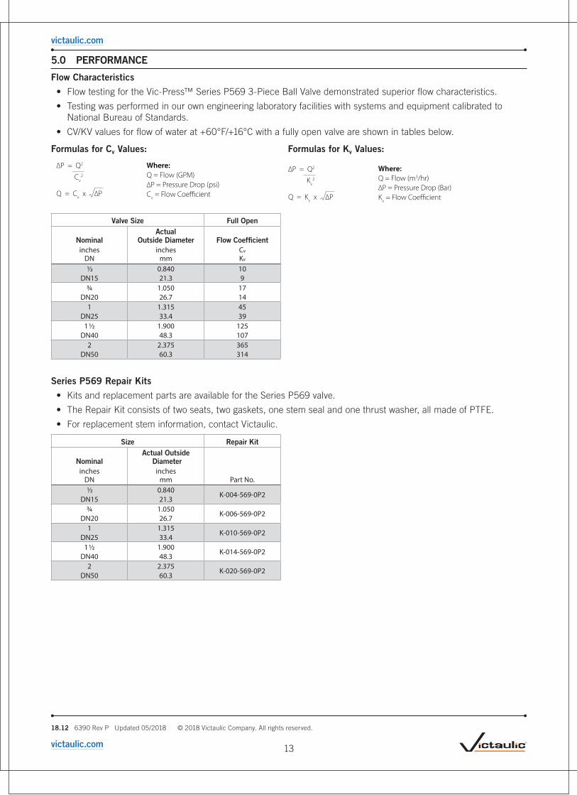
5.0 PERFORMANCE
Flow Characteristics
• Flow testing for the Vic-Press™ Series P569 3-Piece Ball Valve demonstrated superior flow characteristics.
• Testing was performed in our own engineering laboratory facilities with systems and equipment calibrated to National Bureau of Standards.
• CV/KV values for flow of water at +60°F/+16°C with a fully open valve are shown in tables below.
Formulas for Cv Values: Formulas for Kv Values:
∆P = Q2
Cv2
Q = Cv x ∆P
Where:Q = Flow (GPM)∆P = Pressure Drop (psi)Cv = Flow Coe�cient
Q = Flow (m3/hr)∆P = Pressure Drop (Bar)K
v = Flow Coefficient
Where:
Valve Size Full Open
NominalActual
Outside Diameter Flow Coefficientinches
DNinches
mmCv Kv
1/2 0.840 10DN15 21.3 9
3/4 1.050 17DN20 26.7 14
1 1.315 45DN25 33.4 39
1 1/2 1.900 125DN40 48.3 107
2 2.375 365DN50 60.3 314
Series P569 Repair Kits
• Kits and replacement parts are available for the Series P569 valve.
• The Repair Kit consists of two seats, two gaskets, one stem seal and one thrust washer, all made of PTFE.
• For replacement stem information, contact Victaulic.
Size Repair Kit
NominalActual Outside
Diameterinches
DNinches
mm Part No. 1/2 0.840
K-004-569-0P2DN15 21.3
3/4 1.050K-006-569-0P2
DN20 26.71 1.315
K-010-569-0P2DN25 33.4
1 1/2 1.900K-014-569-0P2
DN40 48.32 2.375
K-020-569-0P2DN50 60.3
13
victaulic.com

18.12 6390 Rev P Updated 05/2018 © 2018 Victaulic Company. All rights reserved.
victaulic.com
5.1 PERFORMANCE
Vic-Press™ Brass Body Ball Valve with Stainless Steel Vic-Press™ Schedule 10S Ends
Series P5893 (P x P)
Working Pressure: 300 psi/2068 kPa
• Series P589 Ball Valve is a full port valve with Vic-Press™ Schedule 10S ends for fast, easy installation. The valve, with Vic-Press™ Schedule 10S ends, is designed for service to 300 psi/ 2068 kPa.
• The valve body is constructed from forged brass. The ball is chrome plated brass and seals on PTFE seats. A hollow ball design eliminates unnecessary weight while maintaining flow and mechanical strength. PTFE seats and washers reduce the friction coefficient which eases valve operation.
C
D A
B
Size Dimensions Weight
Nominal
Actual Outside
Diameter
A ± 0.125
3.18 B C D
Approximate (Each)
Flow Coefficient 4 (Fully Open)
inches DN
inches mm
inches mm
inches mm
inches mm
inches mm
lb kg
CV Values KV Values
1/2 0.840 9.030 1.42 3.03 1.06 1.0 11DN15 21.3 229.3 36.1 77.0 26.9 0.5 9.4
3/4 1.050 9.120 1.90 3.74 1.06 1.6 25DN20 26.7 231.7 48.3 95.0 26.9 0.7 21.3
1 1.315 10.11 2.05 3.74 1.19 2.8 36DN25 33.4 256.7 52.1 95.0 30.2 1.3 30.7
1 1/2 1.900 11.18 2.76 5.40 1.38 4.7 112DN40 48.3 283.9 70.1 137.2 35.1 2.1 95.5
2 2.375 12.69 3.15 5.40 1.63 6.9 195DN50 60.3 322.3 80.0 137.2 41.4 3.1 166.3
3 Not approved for use in maritime services.
4 CV/KV values for flow of water at +60°F/+16°C with valve fully open.
NOTES• The Vic-Press™ Schedule 10S ends are of ASTM A312 Type 304 stainless steel.
• The Series P589 Brass Body Ball Valve is NOT ANSI/NSF certified for potable water. For potable water applications use the Series P569 Stainless Steel Ball Valve.
Series P589Valve Body: Forged Brass ASTM B30
Ball: Brass ASTM B30, chrome plated
Stem: Brass ASTM B16
Seats: (PTFE) Polytetrafluoroethylene
Handle: Carbon steel, zinc plated
Stem Nut: Carbon steel, zinc plated
Stem Washer: (PTFE) Polytetrafluoroethylene
Extended Ends: Schedule 10S stainless steel, Type 304
14
victaulic.com

18.12 6390 Rev P Updated 05/2018 © 2018 Victaulic Company. All rights reserved.
victaulic.com
5.2 PERFORMANCE
Pipe Support• Piping joined with Vic-Press™ Schedule 10S System products for Type 304 stainless steel requires support to
carry the weight of pipes and equipment.
• The support or hanging method must be such as to eliminate undue stresses on joints, piping and other components. Additionally, the method of support must be such as to allow movement of the pipes where required and to provide drainage, etc., as may be specified by the designer.
• The maximum hanger spacing corresponds to ASME B31.1, B31.3 or B31.9 as noted, and should be used in conjunction with Victaulic Vic-Press™ Schedule 10S System products on approved Type 304 Schedule 10S stainless steel pipe.
SizeSuggested Max. Span
Between Supports - Feet/meters
NominalActual Outside
Diameter Water Service Gas/Air Serviceinches
DN inches
mm B31.1 B31.3
B31.9 B31.1 B31.3
B31.9 1/2 0.840 6.5 6.5 7.0 7.0 7.0 7.5
DN15 21.3 2.0 2.0 2.1 2.1 2.1 2.3 3/4 1.050 7.5 7.5 8.5 8.0 8.0 9.0
DN20 26.7 2.3 2.3 2.6 2.4 2.4 2.71 1.315 8.5 8.5 10.0 9.0 9.0 10.5
DN25 33.4 2.6 2.6 3.1 2.7 2.7 3.21 1/2 1.900 10.0 10.0 12.5 11.0 11.0 13.5
DN40 48.3 3.1 3.1 3.8 3.6 3.6 4.12 2.375 11.0 11.0 13.0 12.5 12.5 15.5
DN50 60.3 3.6 3.6 4.0 3.8 3.8 4.7
15
victaulic.com

18.12 6390 Rev P Updated 05/2018 © 2018 Victaulic Company. All rights reserved.
victaulic.com
5.3 PERFORMANCE
Thermal Expansion/Contraction • For stainless steel pipes, expansion/contraction will occur with temperature changes at a rate of 1 1/8"/30mm
per 100 feet of pipe per 100°F (96mm per 100 meters of pipe per 100°C). Piping which cannot expand or contract may create substantial stresses within the piping system resulting in damage to the piping system and/or components.
• The change in length due to thermal movement may be absorbed by the flexibility of the piping system, particularly in systems using light wall pipe. This can be done at a simple change in direction using an "L-Bend", or with an offset leg in a "Z-Bend" configuration or with a "U-Bend" (expansion loop).
• A proper design will utilize offset legs of sufficient minimum length prior to any element that will restrict movement (anchors, guides, fixed equipment connection) to minimize pipe stress. In addition, since these methods are symmetric about the offset axis, (i.e.: the expansion loop can open or close in equal amounts), the compensator needs to be sized for the greater of the thermal expansion or contraction from the installed ambient condition.
The following charts designate the minimum offset leg length for each of the aforementioned configurations were developed from the methodology found in ASHRAE Handbook – Systems and Equipment.
∆L
O�set Leg Length
"L-Bend" Expansion CompensatorFigure 1
Displacement ( L) in Inches
Leg
Leng
th in
Inc
hes
∆
“L - Bend” Expansion Compensator
0.0
20.0
40.0
60.0
80.0
100.0
120.0
140.0
160.0
180.0
0.25 0.5 0.75 1 1.25 1.5 1.75 2
2"
1½"
1"
¾"
½"
50mm40mm
25mm20mm15mm
“L - Bend” Expansion Compensator
Displacement ( L) in Millimeters∆
Leg
Leng
th in
Cen
tim
eter
s
0.0
50.0
100.0
150.0
200.0
250.0
300.0
350.0
400.0
450.0
10 20 30 40 50
16
victaulic.com

18.12 6390 Rev P Updated 05/2018 © 2018 Victaulic Company. All rights reserved.
victaulic.com
5.3 PERFORMANCE (Continued)
Thermal Expansion/Contraction
ΔL
O�set Leg Length
"Z-Bend" Expansion Compensator Figure 2
“Z - Bend” Expansion Compensator
Displacement (∆L) in Inches
Leg
Leng
th in
Inc
hes
0.0
20.0
40.0
60.0
80.0
100.0
120.0
0.25 0.5 0.75 1 1.25 1.5 1.75 2
2"
1 ½"
1"
¾"½"
0.0
50.0
100.0
150.0
200.0
250.0
300.0
10 20 30 40 50
50mm40mm
25mm20mm15mm
Displacement ( L) in Millimeters∆
Leg
Leng
th in
Cen
tim
eter
s
“Z - Bend” Expansion Compensator
ΔL ΔL2
2=
ΔL ΔL2
O�set Leg Length2
=
O�set Leg Length
2
"U-Bend" Expansion Compensator Figure 3
0.0
10.0
20.0
30.0
40.0
50.0
60.0
70.0
0.25 0.5 0.75 1 1.25 1.5 1.75 2
2"
1½"
1"
¾" ½"
Displacement ( L) in Inches
Leg
Leng
th in
Inc
hes
“Expansion Loop” Compensator
∆
20.0
40.0
60.0
80.0
100.0
120.0
140.0
160.0
180.0
10 20 30 40 50
50mm40mm
25mm20mm15mm
Displacement ( L) in Millimeters∆
Leg
Leng
th in
Cen
tim
eter
s
“Expansion Loop” Compensator
17
victaulic.com

18.12 6390 Rev P Updated 05/2018 © 2018 Victaulic Company. All rights reserved.
victaulic.com
5.3 PERFORMANCE (Continued)
Thermal Expansion/Contraction
Examples
L-BendA 1"/25mm diameter pipeline will have thermal growth of 1.50"/40mm (ΔL) towards the elbow as shown in the above Figure 1. What is the minimum offset leg length from the elbow to the pipe restriction for the “L-Bend” configuration?
Use the “L-Bend” expansion compensator graph. Find the intersection of ΔL=1.50"/40mm (on the horizontal axis) where it crosses the 1"/25mm pipe curve. At that point, read the “Leg Length in Inches” (on the vertical axis) to determine the minimum offset leg length from the elbow to the pipe restriction. For a thermal growth of 1.50"/40mm of 1"/25mm diameter pipe in an “L-Bend” configuration, the minimum offset leg length should be 105"/2670mm.
Displacement ( L) in Inches
Leg
Leng
th in
Inc
hes
∆
“L - Bend” Expansion Compensator
0.0
20.0
40.0
60.0
80.0
100.0
120.0
140.0
160.0
180.0
0.25 0.5 0.75 1 1.25 1.5 1.75 2
2"
1½"
1"
¾"
½"
Z-BendA 1.50"/40mm diameter pipeline will have thermal growth of 1.25"/32mm between two opposing anchors, however,there is a perpendicular offset designed within the piping system that may be used to accommodate the thermal growth of the main run of pipe. What is the minimum offset leg length required for this “Z-Bend” configuration to accommodate the 1.25"/32mm of thermal growth?
Use the “Z-Bend” expansion compensator graph. Find the intersection of ΔL=1.25"/32mm (on the horizontal axis) where it crosses the 1.50"/40mm pipe curve. At that point, read the “Leg Length in Centimeter” (on the vertical axis) to determine the minimum offset leg length. For a thermal growth of 1.25"/32mm of 1.50"/40mm diameter pipe in a “Z-Bend” configuration, the minimum offset leg length should be 7.25"/186cm.
“Z - Bend” Expansion Compensator
Displacement (∆L) in Inches
Leg
Leng
th in
Inc
hes
0.0
20.0
40.0
60.0
80.0
100.0
120.0
0.25 0.5 0.75 1 1.25 1.5 1.75 2
2"
1 ½"
1"
¾"½"
Expansion LoopA 2"/50mm diameter pipeline will have thermal growth of 1.75"/45mm between two opposing anchors. The configuration of the system is such that there are no changes in direction; straight pipe only between the anchors. To accommodate the thermal growth an expansion loop will be required. What is the minimum offset leg length required for this expansion loop to accommodate the 1.75"/45mm of thermal growth?
Use the “Expansion Loop” compensator graph. Find the intersection of ΔL=1.75"/45mm (on the horizontal axis) where it crosses the 2"/50mm pipe curve. At that point, read the "Leg Length in Inches" (on the vertical axis) to determine the minimum offset leg length of the expansion loop. For a thermal growth of 1.75"/45mm of 2"/50mm diameter pipe in an “L-Bend” configuration, the minimum offset leg length should be 61"/1550mm.
0.0
10.0
20.0
30.0
40.0
50.0
60.0
70.0
0.25 0.5 0.75 1 1.25 1.5 1.75 2
2"
1½"
1"
¾" ½"
Displacement ( L) in Inches
Leg
Leng
th in
Inc
hes
“Expansion Loop” Compensator
∆
18
victaulic.com

18.12 6390 Rev P Updated 05/2018 © 2018 Victaulic Company. All rights reserved.
victaulic.com
5.4 PERFORMANCE
Vic-Press™ PFT510 Tool
PFT510
• The Vic-Press™ PFT510 tool is specifically designed to join Vic-Press™ components to Schedule 10S5 stainless steel pipe. It can also be used for Schedule 5S pipe using Vic-Press™ components.
• Tool package includes one (1) Vic-Press™ PFT510 tool, two (2) 18V Lithium Ion batteries, one (1) battery charger, one (1) tool carrying case, one (1) jaw carrying case, one (1) ½"/15mm jaw, one (1) ¾"/20mm jaw, one (1) 1"/25mm jaw, one (1) 1½"/40mm hinged jaw, one (1) 2"/50mm hinged jaw, and one (1) adapter jaw, one (1) set of insertion gauges, one (1) cleaning brush, and one (1) marker.
• Jaws are included with every tool purchase.
• Vic-Press™ PFT510 is designed for industrial and trade use only
Capacity: ½"/DN15, DN¾/DN20, 1"/DN25, 1 ½"/DN40, 2"/DN50 Schedule 10S stainless steel pipe
Power Charger Requirements: 110 volt/60 cycle/6.5 amp
Optional: 220 volt
5 Can also be used for Schedule 5S pipe using Vic-Press™ components.
NOTES• The Vic-Press™ for Schedule 10S System is not compatible with PFT505 and/or PFT509 tools/components. The Vic-Press™ Schedule 10S System requires
the use of a Vic-Press™ FT510 tool package.
19
victaulic.com
18.12 6390 Rev P Updated 05/2018 © 2018 Victaulic Company. All rights reserved.
victaulic.com
User Responsibility for Product Selection and SuitabilityEach user bears final responsibility for making a determination as to the suitability of Victaulic products for a particular end-use application, in accordance with industry standards and project specifications, as well as Victaulic performance, maintenance, safety, and warning instructions. Nothing in this or any other document, nor any verbal recommendation, advice, or opinion from any Victaulic employee, shall be deemed to alter, vary, supersede, or waive any provision of Victaulic Company's standard conditions of sale, installation guide, or this disclaimer.
Intellectual Property RightsNo statement contained herein concerning a possible or suggested use of any material, product, service, or design is intended, or should be constructed, to grant any license under any patent or other intellectual property right of Victaulic or any of its subsidaries or affiliates covering such use or design, or as a recommendation for the use of such material, product, service, or design in the infringement of any patent or other intellectual property right. The terms “Patented” or “Patent Pending” refer to design or utility patents or patent applications for articles and/or methods of use in the United States and/or other countries.
NoteThis product shall be manufactured by Victaulic or to Victaulic specifications. All products to be installed in accordance with current Victaulic installation/assembly instructions. Victaulic reserves the right to change product specifications, designs and standard equipment without notice and without incurring obligations.
InstallationReference should always be made to the Victaulic installation handbook or installation instructions of the product you are installing. Handbooks are included with each shipment of Victaulic products, providing complete installation and assembly data, and are available in PDF format on our website at www.victaulic.com.
WarrantyRefer to the Warranty section of the current Price List or contact Victaulic for details.
TrademarksVictaulic and all other Victaulic marks are the trademarks or registered trademarks of Victaulic Company, and/or its affiliated entities, in the U.S. and/or other countries.
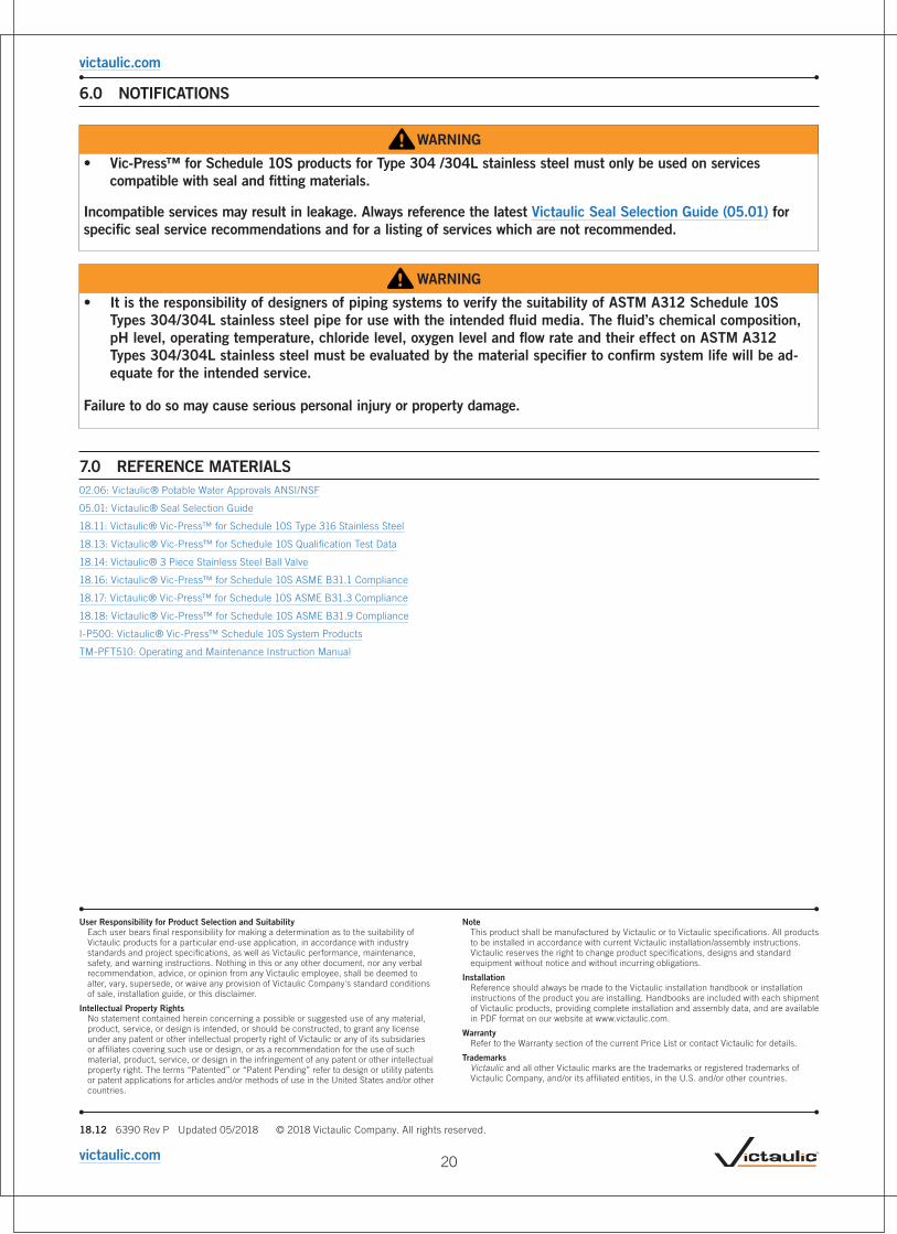
6.0 NOTIFICATIONS
WARNING
• Vic-Press™ for Schedule 10S products for Type 304 /304L stainless steel must only be used on services compatible with seal and fitting materials.
Incompatible services may result in leakage. Always reference the latest Victaulic Seal Selection Guide (05.01) for specific seal service recommendations and for a listing of services which are not recommended.
WARNING
• It is the responsibility of designers of piping systems to verify the suitability of ASTM A312 Schedule 10S Types 304/304L stainless steel pipe for use with the intended fluid media. The fluid’s chemical composition, pH level, operating temperature, chloride level, oxygen level and flow rate and their effect on ASTM A312 Types 304/304L stainless steel must be evaluated by the material specifier to confirm system life will be ad-equate for the intended service.
Failure to do so may cause serious personal injury or property damage.
7.0 REFERENCE MATERIALS02.06: Victaulic® Potable Water Approvals ANSI/NSF
05.01: Victaulic® Seal Selection Guide
18.11: Victaulic® Vic-Press™ for Schedule 10S Type 316 Stainless Steel
18.13: Victaulic® Vic-Press™ for Schedule 10S Qualification Test Data
18.14: Victaulic® 3 Piece Stainless Steel Ball Valve
18.16: Victaulic® Vic-Press™ for Schedule 10S ASME B31.1 Compliance
18.17: Victaulic® Vic-Press™ for Schedule 10S ASME B31.3 Compliance
18.18: Victaulic® Vic-Press™ for Schedule 10S ASME B31.9 Compliance
I-P500: Victaulic® Vic-Press™ Schedule 10S System Products
TM-PFT510: Operating and Maintenance Instruction Manual
20
victaulic.com