
Stainless steel conveyor system X180X - · PDF fileStainless steel conveyor system X180X...
14
© FlexLink 2017 System information 47 PO XLX X85X X180X X300X WL 222X WL 273X WL 374X WL 526X WL 678X CSX GRX FSTX TR APX IDX Stainless steel conveyor system X180X Contents System information ............................................................. 47 Conveyor chain ................................................................... 48 Chain accessories ............................................................... 48 Conveyor beams ................................................................. 49 Slide rails ............................................................................ 51 Tools for conveyor beam..................................................... 52 Drive and idler units – introduction ..................................... 53 Drive units – configuration strings ...................................... 54 End drive units ....................................................................55 Idler units ............................................................................56 Drip catcher .........................................................................57 Bridges, drive unit to idler unit ............................................57 Transfer units ......................................................................58 Plain bends..........................................................................59 Vertical bends......................................................................60 System information Conveyor with focus on robustness and cleanliness The stainless steel conveyor X180X was designed to suit the requirements of food and packaging applications: Environment • Operating temperatures –20 °C to +60 °C • Operating humidity 10% to 95% RH • Noise level at 60 m/min is 68 dBA or less Chain width 175 mm Improved cleanliness conveyor The X180X conveyor system has been evaluated based on field experience and suggestions from customers. With focus on structure rigidness and robustness, easy design, and easier cleaning, several components have been improved with features like better drainage and smaller contact surfaces. Technical characteristics Drive unit capacity ............................. 1250 N Chain tension limit ............................. 1250 N Beam width ........................................ 180 mm Chain width ........................................ 175 mm Chain pitch ......................................... 33,5 mm Item width .......................................... 70–400 mm Maximum item weight ........................ 15 kg Maximum weight on conveyor............ 200 kg Maximum conveyor length ................. 30 m
Transcript of Stainless steel conveyor system X180X - · PDF fileStainless steel conveyor system X180X...
© FlexLink 2017 System information 47
PO
XLX
X85X
X180X
X300X
WL222X
WL273X
WL374X
WL526X
WL678X
CSX
GRX
FSTX
TR
APX
IDX
Stainless steel conveyor system X180XContentsSystem information.............................................................47Conveyor chain ...................................................................48Chain accessories ...............................................................48Conveyor beams .................................................................49Slide rails ............................................................................51Tools for conveyor beam.....................................................52Drive and idler units – introduction .....................................53Drive units – configuration strings ......................................54
End drive units ....................................................................55Idler units ............................................................................56Drip catcher.........................................................................57Bridges, drive unit to idler unit ............................................57Transfer units ......................................................................58Plain bends..........................................................................59Vertical bends......................................................................60
System information
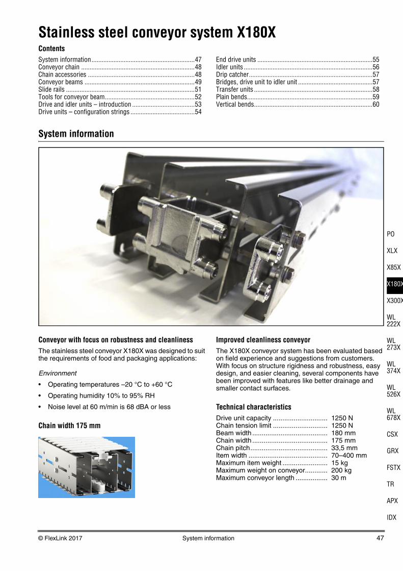
Conveyor with focus on robustness and cleanlinessThe stainless steel conveyor X180X was designed to suit the requirements of food and packaging applications:
Environment
• Operating temperatures –20 °C to +60 °C
• Operating humidity 10% to 95% RH
• Noise level at 60 m/min is 68 dBA or less
Chain width 175 mm
Improved cleanliness conveyorThe X180X conveyor system has been evaluated based on field experience and suggestions from customers. With focus on structure rigidness and robustness, easy design, and easier cleaning, several components have been improved with features like better drainage and smaller contact surfaces.
Technical characteristicsDrive unit capacity ............................. 1250 NChain tension limit ............................. 1250 NBeam width ........................................ 180 mmChain width ........................................ 175 mmChain pitch......................................... 33,5 mmItem width .......................................... 70–400 mmMaximum item weight ........................ 15 kgMaximum weight on conveyor............ 200 kgMaximum conveyor length ................. 30 m
48 Conveyor chain © FlexLink 2017
Conveyor chain
Other chainsSee the Chain guide for selection of other chains.
Chain accessories
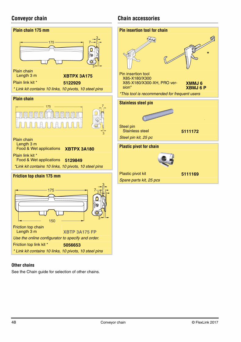
Plain chain 175 mm
Plain chain Length 3 m XBTPX 3A175
Plain link kit * 5122929* Link kit contains 10 links, 10 pivots, 10 steel pins
Plain chain
Plain chain Length 3 mFood & Wet applications XBTPX 3A180
Plain link kit *Food & Wet applications 5129849
*Link kit contains 10 links, 10 pivots, 10 steel pins
Friction top chain 175 mm
Friction top chain Length 3 m XBTP 3A175 FP
Use the online configurator to specify and order.
Friction top link kit * 5056653* Link kit contains 10 links, 10 pivots, 10 steel pins
175
3
7
3
175
175
3
72,5
3150
Pin insertion tool for chain
Pin insertion tool X85-X180/X300X85-X180/X300-XH, PRO ver-sion*
XMMJ 6XBMJ 6 P
*This tool is recommended for frequent users
Stainless steel pin
Steel pinStainless steel 5111172
Steel pin kit, 25 pc
Plastic pivot for chain
Plastic pivot kit 5111169Spare parts kit, 25 pcs
*
.
© FlexLink 2017 Conveyor beams 49
PO
XLX
X85X
X180X
X300X
WL222X
WL273X
WL374X
WL526X
WL678X
CSX
GRX
FSTX
TR
APX
IDX
Conveyor beams
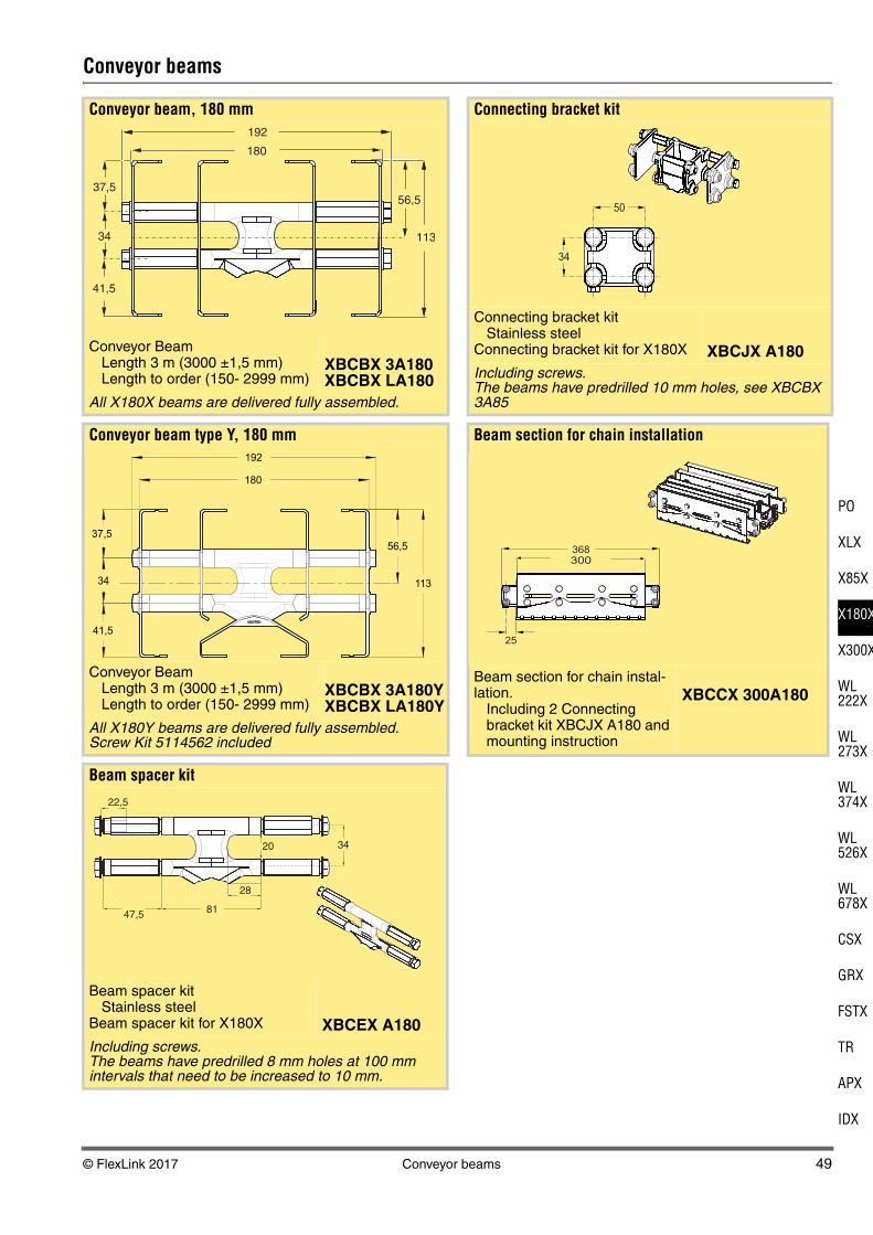
Conveyor beam, 180 mm
Conveyor BeamLength 3 m (3000 ±1,5 mm)Length to order (150- 2999 mm)
XBCBX 3A180XBCBX LA180
All X180X beams are delivered fully assembled.
Conveyor beam type Y, 180 mm
Conveyor BeamLength 3 m (3000 ±1,5 mm)Length to order (150- 2999 mm)
XBCBX 3A180YXBCBX LA180Y
All X180Y beams are delivered fully assembled.Screw Kit 5114562 included
Beam spacer kit
Beam spacer kitStainless steel
Beam spacer kit for X180X XBCEX A180Including screws. The beams have predrilled 8 mm holes at 100 mm intervals that need to be increased to 10 mm.
56,5
113
192
180
37,5
34
41,5
113
56,5
180
37,5
34
41,5
192
81
28
20 34
47,5
22,5
Connecting bracket kit
Connecting bracket kitStainless steel
Connecting bracket kit for X180X XBCJX A180Including screws. The beams have predrilled 10 mm holes, see XBCBX 3A85
Beam section for chain installation
Beam section for chain instal-lation.
Including 2 Connecting bracket kit XBCJX A180 and mounting instruction
XBCCX 300A180
50
34
368
25
300
50 Conveyor beams © FlexLink 2017
Conveyor beams (continued)
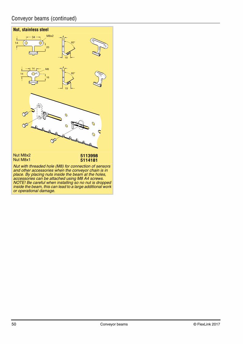
Nut, stainless steel
Nut M8x2Nut M8x1
5113998 5114181
Nut with threaded hole (M8) for connection of sensors and other accessories when the conveyor chain is in place. By placing nuts inside the beam at the holes, accessories can be attached using M8 A4 screws.NOTE! Be careful when installing so no nut is dropped inside the beam, this can lead to a large additional work or operational damage.
M8
14
14
34
19
M8x2
14 60°
19
60°
16
20
4
4
© FlexLink 2017 Slide rails 51
PO
XLX
X85X
X180X
X300X
WL222X
WL273X
WL374X
WL526X
WL678X
CSX
GRX
FSTX
TR
APX
IDX
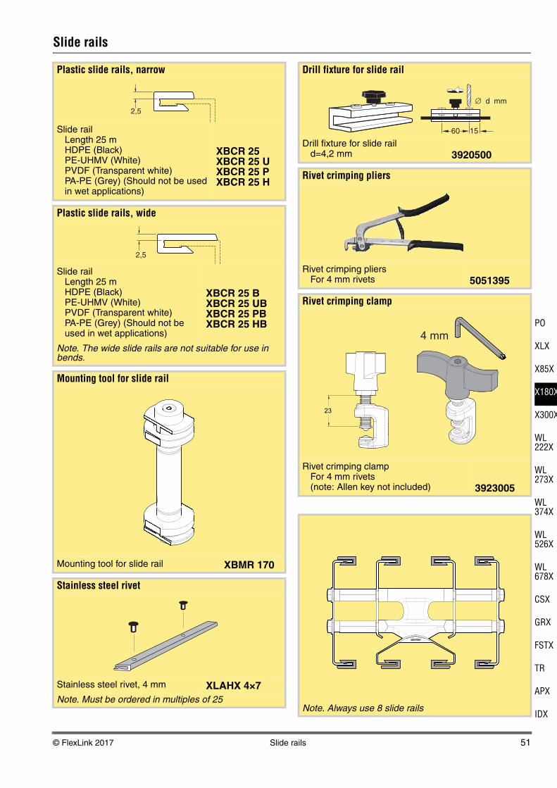
Slide rails
Plastic slide rails, narrow
Slide railLength 25 mHDPE (Black)PE-UHMV (White)PVDF (Transparent white)PA-PE (Grey) (Should not be used in wet applications)
XBCR 25XBCR 25 UXBCR 25 PXBCR 25 H
Plastic slide rails, wide
Slide railLength 25 mHDPE (Black)PE-UHMV (White)PVDF (Transparent white)PA-PE (Grey) (Should not be used in wet applications)
XBCR 25 BXBCR 25 UBXBCR 25 PBXBCR 25 HB
Note. The wide slide rails are not suitable for use in bends.
Mounting tool for slide rail
Mounting tool for slide rail XBMR 170
Stainless steel rivet
Stainless steel rivet, 4 mm XLAHX 4×7Note. Must be ordered in multiples of 25
2,5
2,5
Drill fixture for slide rail
Drill fixture for slide raild=4,2 mm 3920500
Rivet crimping pliers
Rivet crimping pliersFor 4 mm rivets 5051395
Rivet crimping clamp
Rivet crimping clampFor 4 mm rivets(note: Allen key not included) 3923005
Note. Always use 8 slide rails
d mm∅
1560
23
4 mm

52 Tools for conveyor beam © FlexLink 2017
Tools for conveyor beam
Drill fixture
Drill fixture 5114621For use when additional holes are needed on the beam sides.Including:Drill 4,5 mmDrill 8,3 mmDrill 11,0 mmand instructions for use.
Drill
Twist Drills DIN 338 HSS-E (Co 8) Type N-HD Cobalt Alloyed, Split PointDrill 11,0 mmDrill 10,2 mmDrill 8,3 mmDrill 4,5 mmDrill 4,2 mm (for 3920500)
51150505115056511505151150525115053
For high strength alloys on CrNi base such as Hastelloy, Inconel, Monel, Nimonic, stainless steels, head and acid-proof steels (up to 1400 N/mm² tensile strength).
© FlexLink 2017 Drive and idler units – Introduction 53
PO
XLX
X85X
X180X
X300X
WL222X
WL273X
WL374X
WL526X
WL678X
CSX
GRX
FSTX
TR
APX
IDX
Drive and idler units – Introduction
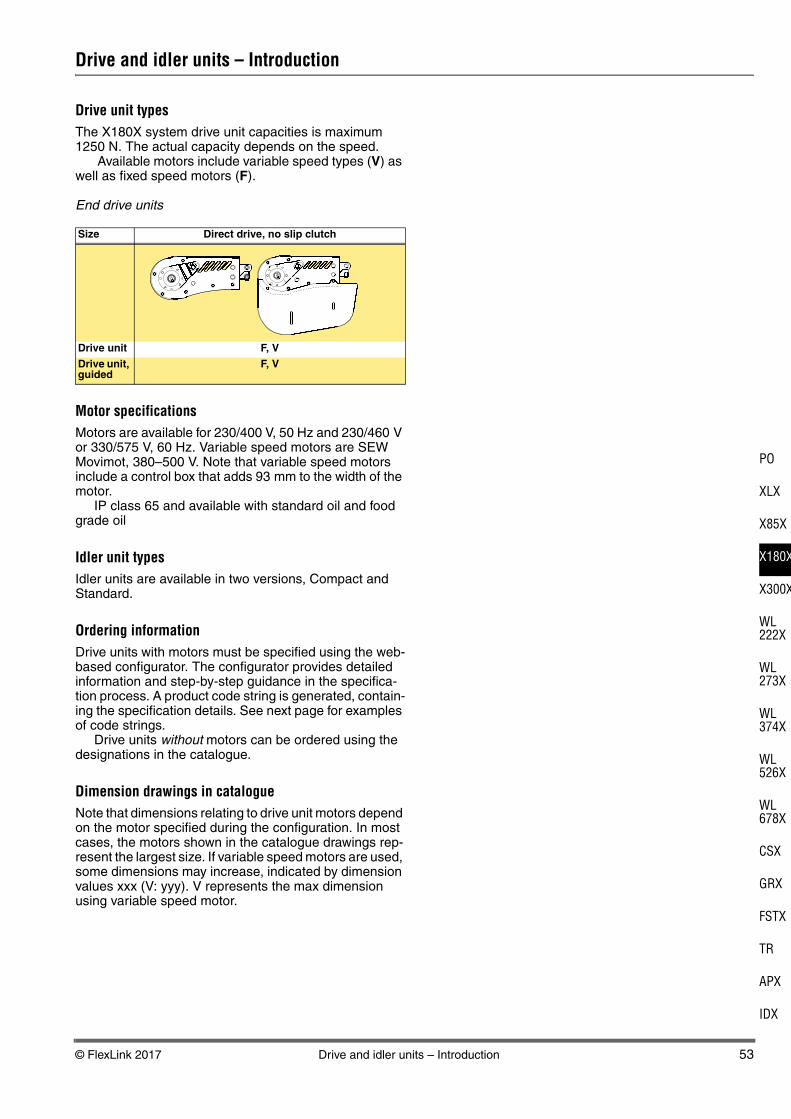
Drive unit typesThe X180X system drive unit capacities is maximum 1250 N. The actual capacity depends on the speed.
Available motors include variable speed types (V) as well as fixed speed motors (F).
End drive units
Motor specificationsMotors are available for 230/400 V, 50 Hz and 230/460 V or 330/575 V, 60 Hz. Variable speed motors are SEW Movimot, 380–500 V. Note that variable speed motors include a control box that adds 93 mm to the width of the motor.
IP class 65 and available with standard oil and food grade oil
Idler unit typesIdler units are available in two versions, Compact and Standard.
Ordering informationDrive units with motors must be specified using the web-based configurator. The configurator provides detailed information and step-by-step guidance in the specifica-tion process. A product code string is generated, contain-ing the specification details. See next page for examples of code strings.
Drive units without motors can be ordered using the designations in the catalogue.
Dimension drawings in catalogueNote that dimensions relating to drive unit motors depend on the motor specified during the configuration. In most cases, the motors shown in the catalogue drawings rep-resent the largest size. If variable speed motors are used, some dimensions may increase, indicated by dimension values xxx (V: yyy). V represents the max dimension using variable speed motor.
Size Direct drive, no slip clutch
Drive unit F, V
Drive unit, guided
F, V

54 Drive units – configuration strings © FlexLink 2017
Drive units – configuration strings
Below, two examples of text strings obtained from the configurator with explanations are presented.
Drive unit with fixed speed motor
Drive unit with variable speed motor
Item no - Drive type
A – 0-UnitHNP: Direct drive, no slip clutch....V: Variable speed
B – Motor positionL: LeftR: Right
C – End drive with guided chainG: Guided (position is omitted for non-guided)
D – SpeedV...: Fixed speed... m/minV... -...: Variable speed range...-... m/min
E – GearboxSA37: SEW motor type SA37
F – Movimot sizeMM03: SEW Movimot type, 0,33 kWMM05: SEW Movimot type, 0,55 kWMM07: SEW Movimot type, 0,75 kWMM11: SEW Movimot type, 1,1 kW(position is omitted for fixed speed motors)
G – Electrical environment50/230: 50 Hz, 230 V50/400: 50 Hz, 400 V60/230: 60 Hz, 230 V60/460: 60 Hz, 460 V60/575: 60 Hz, 575 V50/380-500: SEW Movimot variable speed motor60/380-500: SEW Movimot variable speed motor
H – Motor power... kW: Motor power, kW(position is omitted for variable speed motorssee position F)
I – Thermal protectionNo: No thermal protectionTF: Thermal protection type TFTH: Thermal protection type TH(position is omitted for variable speed motors)
J – Hybrid cableNo: No hybrid cableC: Hybrid cable included in SEW Movimot(position is omitted for fixed speed motors)
K – FieldbusNo: No fieldbusP: Profibus fieldbus, maintenance switchD: DeviceNet fieldbus, maintenance switch (position is omitted for fixed speed motors)
Item no A B C D E G H IXBEBX A180 HNP - L - G - V4 - SA37 - 50/230 - 0,18kW - TF
Item no A B D E F G J KXBEBX A180 HNPV - L - V6-15 - SA37 - MM03 - 50/380-500 - C - P
XBEBX: End drive
© FlexLink 2017 End drive units 55
PO
XLX
X85X
X180X
X300X
WL222X
WL273X
WL374X
WL526X
WL678X
CSX
GRX
FSTX
TR
APX
IDX
End drive units
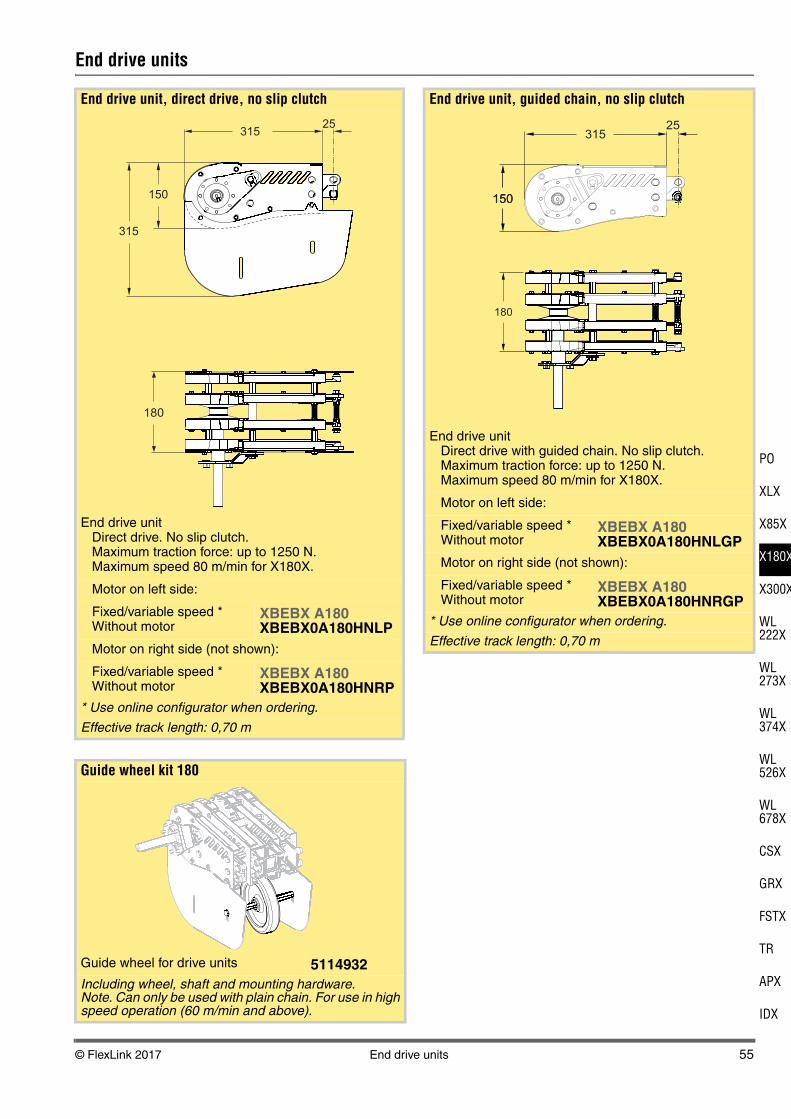
End drive unit, direct drive, no slip clutch
End drive unitDirect drive. No slip clutch.Maximum traction force: up to 1250 N.Maximum speed 80 m/min for X180X.
Motor on left side:
Fixed/variable speed *Without motor
XBEBX A180XBEBX0A180HNLP
Motor on right side (not shown):
Fixed/variable speed *Without motor
XBEBX A180XBEBX0A180HNRP
* Use online configurator when ordering.
Effective track length: 0,70 m
Guide wheel kit 180
Guide wheel for drive units 5114932Including wheel, shaft and mounting hardware. Note. Can only be used with plain chain. For use in high speed operation (60 m/min and above).
150
31525
315
180
End drive unit, guided chain, no slip clutch
End drive unitDirect drive with guided chain. No slip clutch.Maximum traction force: up to 1250 N.Maximum speed 80 m/min for X180X.
Motor on left side:
Fixed/variable speed *Without motor
XBEBX A180XBEBX0A180HNLGP
Motor on right side (not shown):
Fixed/variable speed *Without motor
XBEBX A180XBEBX0A180HNRGP
* Use online configurator when ordering.
Effective track length: 0,70 m
180
150
31525
150

56 Idler units © FlexLink 2017
Idler units
Note!Always use pinch point protective cover for idler ends to protect persons from clamp risk.
Idler end unit
Idler end unit, X180X XBEJX A180Effective track length: 0,70 m.
Protective cover for Idler end
Protective cover for Idler end unit XBEJX A180 XBSJX A180
180
150
31525
203180
127
113204
12
315
184
100
Idler end unit, Compact
Idler end unit, compact X180X XBEJX A180 SEffective track length: 0,35 m.
Protective cover for Idler end, Compact
Protective cover for Idler end unit XBEJX A180 S XBSJX A180 S
180
113
13025
203180
83
144
107
113167
11
130

© FlexLink 2017 Drip catcher 57
PO
XLX
X85X
X180X
X300X
WL222X
WL273X
WL374X
WL526X
WL678X
CSX
GRX
FSTX
TR
APX
IDX
Drip catcher
Bridges, drive unit to idler unit
Drip catcher kit
Drip catcher kit 5114763For drive units and idler ends, to be used together with conveyor beams type Y with protected return beams including 5114562 Screw kit.
Screw kit
Screw kit 5114562For return beam, type Y, 85 mm, or Drip catcher kit.
Bridge, idler compact to drive unit
Bridge (see Note) 5115196Including roller bridge and mounting hardware.Suitable for connecting idler compact to drive unit.
158
Bridge, idler to drive unit
Bridge (see Note) 5115197Including roller bridge and mounting hardware.Suitable for connecting idler to drive unit.
178

58 Transfer units © FlexLink 2017
Transfer units
Side transfer, left
Side transfer
For optional mounting of Idler end unit or Drive unit at the end (A) or (B) XBCPX 180 LEffective track length: 3 m
1150
180
350
Side transfer, right
Side transfer
For optional mounting of Idler end unit or Drive unit at the end (A) or (B) XBCPX 180 REffective track length: 3 m
Slack protection kit
Slack protection kit 5115027Recommended use when Side transfer is installed with End drive unit H, direct drive, no slip clutch.
1150
180
350
© FlexLink 2017 Plain bends 59
PO
XLX
X85X
X180X
X300X
WL222X
WL273X
WL374X
WL526X
WL678X
CSX
GRX
FSTX
TR
APX
IDX
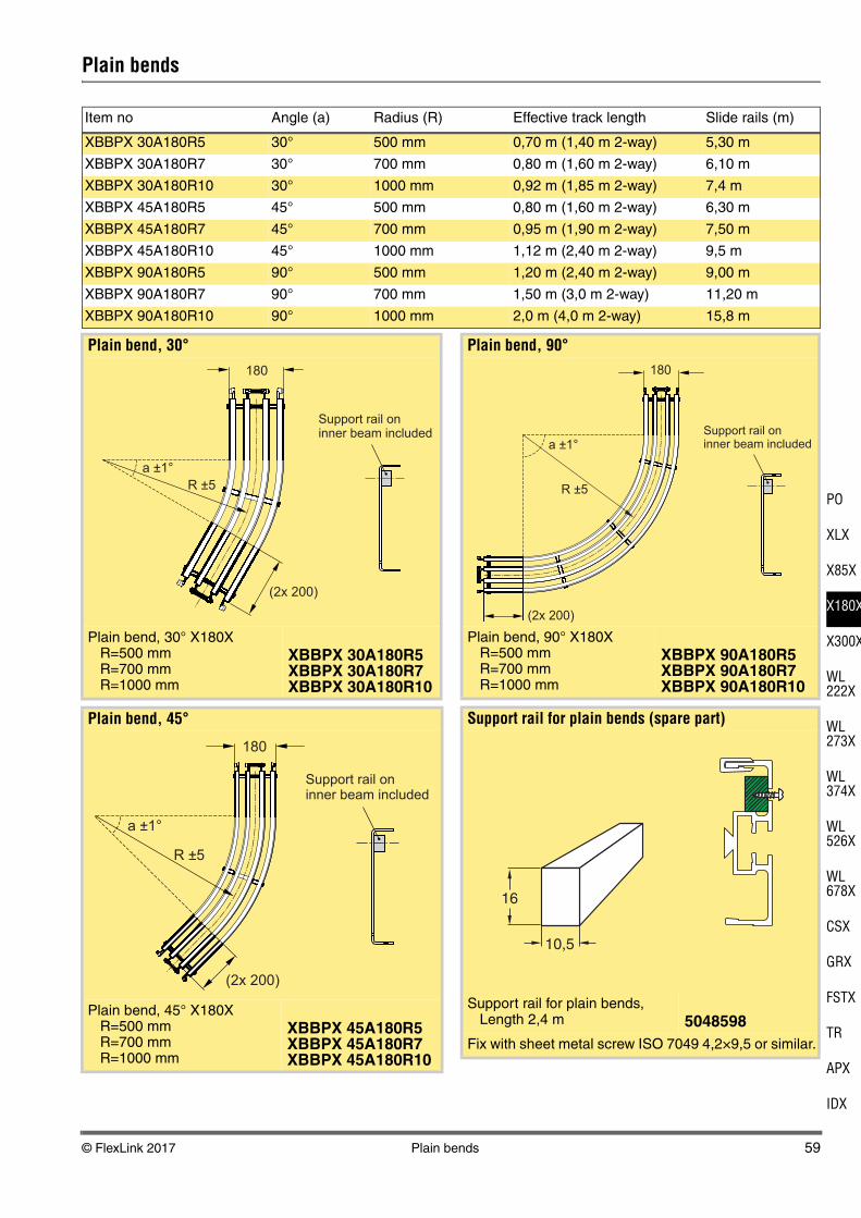
Plain bends
Item no Angle (a) Radius (R) Effective track length Slide rails (m)
XBBPX 30A180R5 30° 500 mm 0,70 m (1,40 m 2-way) 5,30 m
XBBPX 30A180R7 30° 700 mm 0,80 m (1,60 m 2-way) 6,10 m
XBBPX 30A180R10 30° 1000 mm 0,92 m (1,85 m 2-way) 7,4 m
XBBPX 45A180R5 45° 500 mm 0,80 m (1,60 m 2-way) 6,30 m
XBBPX 45A180R7 45° 700 mm 0,95 m (1,90 m 2-way) 7,50 m
XBBPX 45A180R10 45° 1000 mm 1,12 m (2,40 m 2-way) 9,5 m
XBBPX 90A180R5 90° 500 mm 1,20 m (2,40 m 2-way) 9,00 m
XBBPX 90A180R7 90° 700 mm 1,50 m (3,0 m 2-way) 11,20 m
XBBPX 90A180R10 90° 1000 mm 2,0 m (4,0 m 2-way) 15,8 m
Plain bend, 30°
Plain bend, 30° X180XR=500 mmR=700 mmR=1000 mm
XBBPX 30A180R5XBBPX 30A180R7XBBPX 30A180R10
Plain bend, 45°
Plain bend, 45° X180XR=500 mmR=700 mmR=1000 mm
XBBPX 45A180R5XBBPX 45A180R7XBBPX 45A180R10
(2x 200)
R ±5
a ±1°
180
(2x 200)
R ±5
a ±1°
180
Plain bend, 90°
Plain bend, 90° X180XR=500 mmR=700 mmR=1000 mm
XBBPX 90A180R5XBBPX 90A180R7XBBPX 90A180R10
Support rail for plain bends (spare part)
Support rail for plain bends,Length 2,4 m 5048598
Fix with sheet metal screw ISO 7049 4,2×9,5 or similar.
(2x 200)
R ±5
a ±1°
180
16
10,5
60 Vertical bends © FlexLink 2017
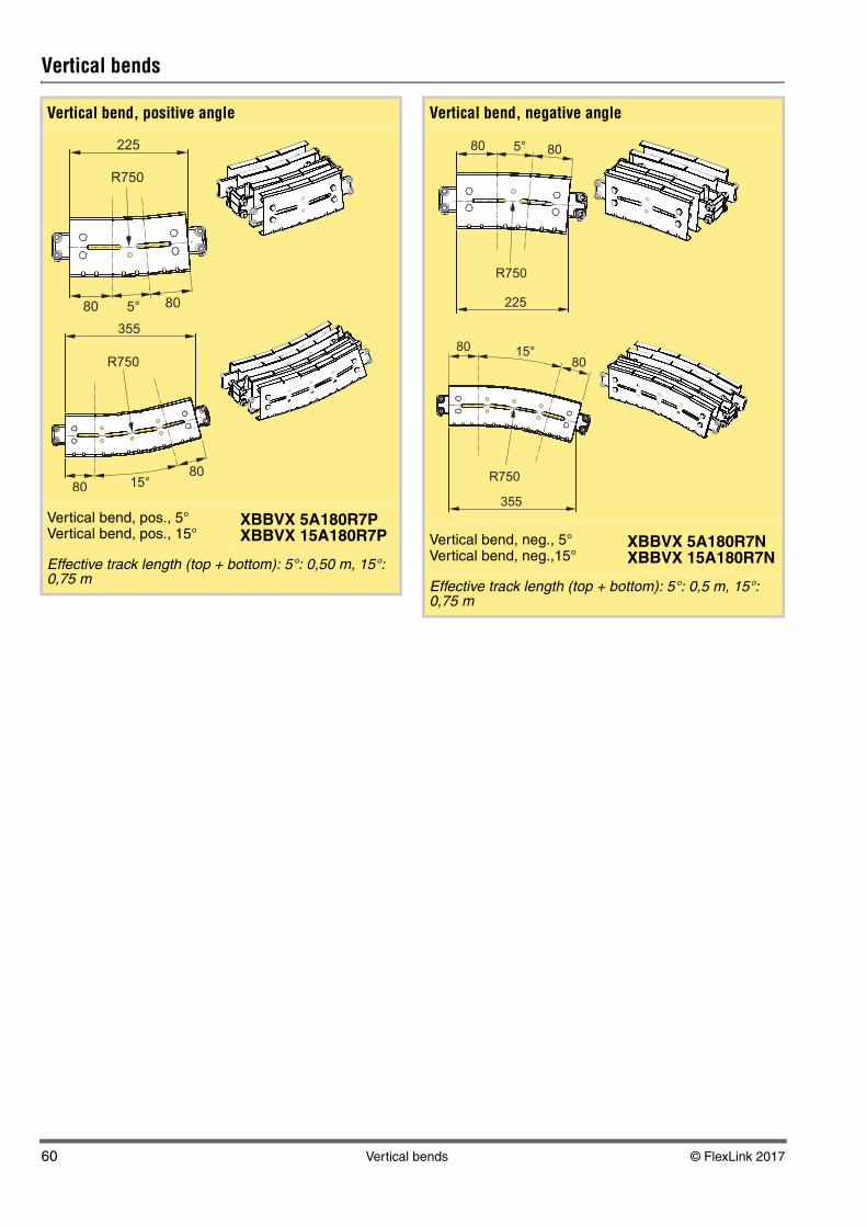
Vertical bends
Vertical bend, positive angle
Vertical bend, pos., 5°Vertical bend, pos., 15°
XBBVX 5A180R7PXBBVX 15A180R7P
Effective track length (top + bottom): 5°: 0,50 m, 15°: 0,75 m
R750
225
80 5° 80
R750
355
80 15°80
Vertical bend, negative angle
Vertical bend, neg., 5°Vertical bend, neg.,15°
XBBVX 5A180R7NXBBVX 15A180R7N
Effective track length (top + bottom): 5°: 0,5 m, 15°: 0,75 m
R750
225
80 5° 80
R750
355
80 15°80