STAINLESS STEEL 5-, 10-, and 15-Gallon Pressure Tanks€¦ · 5-, 10-, and 15-Gallon Pressure Tanks...
22
308369S EN Instructions-Parts List STAINLESS STEEL 5-, 10-, and 15-Gallon Pressure Tanks Industrial grade pressure tanks used to supply, agitate, and pressurize finishing liquids. For professional use only. Maximum Air Inlet Pressure 100 psi (0.7 MPa, 7 bar) Maximum Working Fluid Pressure Low-Pressure Regulated Tank 15 psi (0.1 MPa, 1 bar) (for HVLP or low-pressure, fine-adjustment applications) High-Pressure Regulated Tank 100 psi (0.7 MPa, 7 bar) See page 2 for model information, including approvals. Important Safety Instructions Read all warnings and instructions in this manual. Save these instructions. Low-Pressure Tank Low-Pressure Tank with Agitator High-Pressure Tank High-Pressure Tank with Agitator 3084a 3188c 3088b 3189c ASME
Transcript of STAINLESS STEEL 5-, 10-, and 15-Gallon Pressure Tanks€¦ · 5-, 10-, and 15-Gallon Pressure Tanks...

308369SEN
Instructions-Parts List
STAINLESS STEEL5-, 10-, and 15-Gallon Pressure Tanks
Industrial grade pressure tanks used to supply, agitate, and pressurize finishing liquids. For professional use only.Maximum Air Inlet Pressure 100 psi (0.7 MPa, 7 bar)
Maximum Working Fluid PressureLow-Pressure Regulated Tank 15 psi (0.1 MPa, 1 bar)
(for HVLP or low-pressure, fine-adjustment applications)High-Pressure Regulated Tank 100 psi (0.7 MPa, 7 bar)
See page 2 for model information, including approvals.
Important Safety InstructionsRead all warnings and instructions in this manual. Save these instructions.
Low-Pressure Tank
Low-Pressure Tankwith Agitator
High-Pressure Tank
High-Pressure Tankwith Agitator
3084a
3188c
3088b
3189c
ASME

Table of Contents
2 308369S
Table of ContentsTable of Contents . . . . . . . . . . . . . . . . . . . . . . . . . . 2Models . . . . . . . . . . . . . . . . . . . . . . . . . . . . . . . . . . . 2Warnings . . . . . . . . . . . . . . . . . . . . . . . . . . . . . . . . . 3Typical Systems . . . . . . . . . . . . . . . . . . . . . . . . . . . 5Installation . . . . . . . . . . . . . . . . . . . . . . . . . . . . . . . . 6
Pressure Relief Procedure . . . . . . . . . . . . . . . . . 6Grounding . . . . . . . . . . . . . . . . . . . . . . . . . . . . . 6Recommended Hose Sizes (general purpose) . 6Installing a Heavy Duty Agitator . . . . . . . . . . . . . 6Connecting Hoses . . . . . . . . . . . . . . . . . . . . . . . 6
Operation . . . . . . . . . . . . . . . . . . . . . . . . . . . . . . . . . 7Preparing the Fluid . . . . . . . . . . . . . . . . . . . . . . . 7Filling the Tank . . . . . . . . . . . . . . . . . . . . . . . . . . 7Operating the Pressure Tank . . . . . . . . . . . . . . . 7Safety Relief Valve . . . . . . . . . . . . . . . . . . . . . . . 7
Maintenance . . . . . . . . . . . . . . . . . . . . . . . . . . . . . . . 8Cleaning the Tank . . . . . . . . . . . . . . . . . . . . . . . 8
Notes . . . . . . . . . . . . . . . . . . . . . . . . . . . . . . . . . . . . . 9Parts . . . . . . . . . . . . . . . . . . . . . . . . . . . . . . . . . . . . 10
Low-Pressure Stainless Steel Tanks . . . . . . . . 10Low-Pressure Stainless Steel Tanks
with Agitator . . . . . . . . . . . . . . . . . . . . . . . . 12High-Pressure Stainless Steel Tanks . . . . . . . . 14High-Pressure Stainless Steel Tanks
with Agitator . . . . . . . . . . . . . . . . . . . . . . . . 16Accessories . . . . . . . . . . . . . . . . . . . . . . . . . . . . . . 18Dimensions . . . . . . . . . . . . . . . . . . . . . . . . . . . . . . . 20Technical Data . . . . . . . . . . . . . . . . . . . . . . . . . . . . 21Graco Standard Warranty . . . . . . . . . . . . . . . . . . . 22
Models
All pressure tanks listed are CE approved to the Pressure Equipment Directive (Category II). Items marked * also are
approved to
Tank Size gallons (liters)
Low-Pressure Tank Series B
Low-Pressure Tank with Agitator Series C
High-Pressure Tank Series B
High-Pressure Tank with Agitator Series C
5 (19) 236143 236146* 236149 236152*
10 (38) 236144 236147* 236150, 243589 236153*
15 (57) 236145 236148* 236151 236154*
0359 II 1/2 G T6ITS03ATEX11251

Warnings
308369S 3
WarningsThe following warnings are for the setup, use, grounding, maintenance, and repair of this equipment. The exclama-tion point symbol alerts you to a general warning and the hazard symbols refer to procedure-specific risks. When these symbols appear in the body of this manual or on warning labels, refer back to these Warnings. Product-specific hazard symbols and warnings not covered in this section may appear throughout the body of this manual where applicable.
WARNINGWARNINGWARNINGWARNINGEQUIPMENT MISUSE HAZARDMisuse can cause death or serious injury.• Do not operate the unit when fatigued or under the influence of drugs or alcohol.• Do not exceed the maximum working pressure or temperature rating of the lowest rated system com-
ponent. See Technical Data in all equipment manuals.• Use fluids and solvents that are compatible with equipment wetted parts. See Technical Data in all
equipment manuals. Read fluid and solvent manufacturer’s warnings. For complete information about your material, request MSDS from distributor or retailer.
• Do not leave the work area while equipment is energized or under pressure.• Turn off all equipment and follow the Pressure Relief Procedure when equipment is not in use.• Check equipment daily. Repair or replace worn or damaged parts immediately with genuine manufac-
turer’s replacement parts only.• Do not alter or modify equipment. Alterations or modifications may void agency approvals and create
safety hazards.• Make sure all equipment is rated and approved for the environment in which you are using it.• Use equipment only for its intended purpose. Call your distributor for information.• Route hoses and cables away from traffic areas, sharp edges, moving parts, and hot surfaces.• Do not kink or over bend hoses or use hoses to pull equipment.• Keep children and animals away from work area.• Comply with all applicable safety regulations.
FIRE AND EXPLOSION HAZARD Flammable fumes, such as solvent and paint fumes, in work area can ignite or explode. To help prevent fire and explosion:• Use equipment only in well ventilated area.• Eliminate all ignition sources; such as pilot lights, cigarettes, portable electric lamps, and plastic drop
cloths (potential static arc). • Keep work area free of debris, including solvent, rags and gasoline.• Do not plug or unplug power cords, or turn power or light switches on or off when flammable fumes are
present.• Ground all equipment in the work area. See Grounding instructions.• Use only grounded hoses.• Hold gun firmly to side of grounded pail when triggering into pail. Do not use pail liners unless they are
antistatic or conductive.• Stop operation immediately if static sparking occurs or you feel a shock. Do not use equipment until
you identify and correct the problem.• Keep a working fire extinguisher in the work area.

Warnings
4 308369S
MOVING PARTS HAZARDMoving parts can pinch, cut or amputate fingers and other body parts.• Keep clear of moving parts.• Do not operate equipment with protective guards or covers removed.• Pressurized equipment can start without warning. Before checking, moving, or servicing equipment,
follow the Pressure Relief Procedure and disconnect all power sources.
TOXIC FLUID OR FUMES HAZARDToxic fluids or fumes can cause serious injury or death if splashed in the eyes or on skin, inhaled, or swal-lowed.• Read MSDSs to know the specific hazards of the fluids you are using.• Store hazardous fluid in approved containers, and dispose of it according to applicable guidelines.
WARNINGWARNINGWARNINGWARNING

Typical Systems
308369S 5
Typical SystemsReference numbers and letters in parentheses in the text refer to references in the illustrations and the parts draw-ings.
See page 18 for Accessories that are available from Graco. Be sure that all accessories are properly sized to with-stand the pressures in the system.
FIG. 1
KEYA Air supply hose G Air regulator & filter:
1/4-1/8 npt outlets (2)12-14 npt inlet
B Main air supplyC Ground clamp & wireD Atomizing air hose H Agitator air hoseE Fluid hose 4 Safety valveF Air spray gun 17 Air inlet ball valve;
3/8-18 npsm(m) x 3/8-18 npt (m)18 Fluid outlet ball valve;
3/8-18 npsm (m) x 3/8-18 npt (m)33 Tank air regulator
33
17
18
4
F
B
E
A
H
D
G
C
E
3186b

Installation
6 308369S
Installation
Pressure Relief Procedure
1. Shut off the air supply to the tank by closing the air inlet valve (17). Refer to Fig. 2.
2. Open the drain cock fitting (7) by turning it counter-clockwise.
3. Wait until there is no air escaping through the drain cock fitting before removing the cover or opening the fill port.
4. Leave the drain cock fitting (7) open until you have reinstalled the cover or fill port.
NOTE: Tighten the c-clamp to 8-10 ft-lbs. Approximately 1/2 to 1 turn past hand tight.
GroundingCheck your local code for detailed grounding instruc-tions for your area and type of equipment. Be sure to ground the pressure tank by connecting one end of a 12 awg (1.5 mm2) minimum ground wire to the pressure tank and the other end of the wire to a true earth ground.
Recommended Hose Sizes (general purpose)
Installing a Heavy Duty Agitator To install a heavy duty air operated agitator, see manual 308371. This agitator is recommended for fluid viscosi-ties over 800 centipoise (cp).
Connecting Hoses Refer to Fig. 1, page 4. Install an air regulator and filter (G) upstream from the air inlet ball valve (17) to remove dirt and moisture from the compressed air supply (B). See Accessories on page 16. Connect an air supply hose (A) between the air inlet ball valve (17) and an air outlet of the air regulator and filter (G).
Connect the atomizing air hose (D) to the air spray gun (F) from an air outlet of air regulator and filter (G) or from the gun air regulator kit (see Accessories on page 18).
Connect a fluid hose (E) between the 3/8 npt(m) fluid outlet ball valve (18) and the fluid inlet of air spray gun (F).
Always maintain a minimum of 1 in. clearance between rotating agitator parts and container to prevent sparks from contact.
The pressure tanks remain pressurized until pressure is manually relieved. To reduce the risk of serious injury from pressurized fluid or accidental spray from the gun, always follow this procedure to relieve pressure in the tank at the following times:
• Before you check or service any part of the spray system
• Before you loosen or remove the pressure tank cover or fill port
• Whenever you stop spraying
FIG. 23187b
7
17
Fluid AirFor runs of: Use: For runs of: Use:0 to 35 ft (0 to 11 m)
3/8” ID 0 to 50 ft (0 to 15 m)
5/16” ID
35 to 100 ft (11 to 30 m)
1/2” ID 50 to 100 ft (15 to 30 m)
3/8” ID
100 to 200 ft (30 to 61 m)
3/4” ID 100 ft+ (30 m+)
1/2” ID

Operation
308369S 7
Operation
Preparing the Fluid Prepare the fluid according to the manufacturer’s instructions. Strain the fluid to remove large particles that could clog the spray gun or the siphon tube.
Filling the Tank 1. Before filling the tank, follow the Pressure Relief
Procedure on page 6.
2. Place fluid into the tank by one of the following methods:
a. Remove the cover and place a 5-gallon pail of fluid in the 5-gallon tank (see Dimensions, page 21).
b. Remove the cover and place a 5-gallon anti-static polyethylene liner in the 5-gallon tank. Pour the fluid into the antistatic polyethylene liner (see Accessories, page 18).
3. Fill the tank through the fill port in the cover, or remove the cover and pour fluid directly into the tank. Do not exceed the suggested capacity (5, 10 or 15 gallons) of your tank.
NOTE: If a 5-gallon pail is used inside the tank, an adjustment is required to the agitator paddle position to avoid interference. See instruction manual 308371 for adjustment information.
4. Replace the cover or the filler cap (20) and tighten the c-clamp handles to 8-10 ft-lbs, approximately 1/2 to 1 turn past hand tight.
Operating the Pressure Tank 1. Close the tank air regulator (33) by turning the knob
counterclockwise and turn on the air supply. See FIG. 2.
2. Open the air inlet ball valve (17).
3. Start and adjust the agitator (if it is used) as explained in the separate instruction manual 308371.
4. Adjust the tank air regulator (33) to the approximate pressure desired.
5. Open fluid outlet ball valve (18).
6. Turn on the atomizing air to the air spray gun. Test spray a small area and adjust the pressure as nec-essary. Always use the lowest possible air pressure to obtain the desired results.
Safety Relief Valve A safety relief valve (4) will automatically relieve the tank pressure when the air pressure exceeds 95 to 100 psi (0.5 to 0.6 MPa, 6.5 to 7 bar). Refer to FIG. 2 or the parts drawings.
Each week, check the working order of the safety relief valve. Only as a test, raise the air pressure to 95 to 105 psi (0.5 to 0.6 MPa, 6.5 to 7.1 bar). If the safety relief valve does not relieve the pressure, replace it immedi-ately. Do not attempt to repair it. The safety relief valve will reset automatically when the pressure is relieved.
This is a pressurized tank. Always follow the Pressure Relief Procedure on page 5 before opening the tank cover or fill port. This reduces the risk of serious injury, including splashing in the eyes or on the skin, or injury from moving parts. These injuries can result if the tank pressure is not fully relieved.
Over pressurizing the tank or accessories could cause a part to rupture. To reduce the risk of serious injury, including splashing in the eyes or on the skin, and property damage, never exceed the maximum air and fluid working pressure of the lowest rated component in your system.
NOTICE
Do not operate the agitator at a high speed for a long period of time. Excessive agitator speed can cause foaming of fluid (making the fluid unusable), vibration, and increased wear on the parts. Always agitate the fluid only enough to maintain even mixing.

Maintenance
8 308369S
Maintenance
Cleaning the Tank 1. First follow the Pressure Relief Procedure on page
6.
2. Follow the procedure below to force the fluid back through the hose and into the tank:
a. Loosen the spray gun air cap retaining ring about two turns.
b. Hold a rag over the air cap and trigger the gun for a few seconds, until the fluid is forced back into the tank.
3. Remove the tank cover.
4. Empty the fluid from the tank and pour a suitable amount of solvent into it.
5. Replace the tank cover and tighten the c-clamps, to 8-10 ft-lbs, approximately 1/2 to 1 turn past hand tight.
6. Close the drain cock fitting (7).
7. Turn on the air supply.
8. Hold a metal part of the gun against a grounded metal waste container and trigger the gun into the waste container until clean solvent comes from the gun.
9. Remove the solvent from the system and wipe the inside of the tank and the rest of the equipment clean with a solvent-dampened rag.
See separate instruction manual 308371 for informa-tion on agitator maintenance.
NOTICE
Be sure that the solvent you use is compatible with the fluid being sprayed. Refer to the Technical Data section on page 21.

Notes
308369S 9
Notes
Parts
10 308369S
Parts
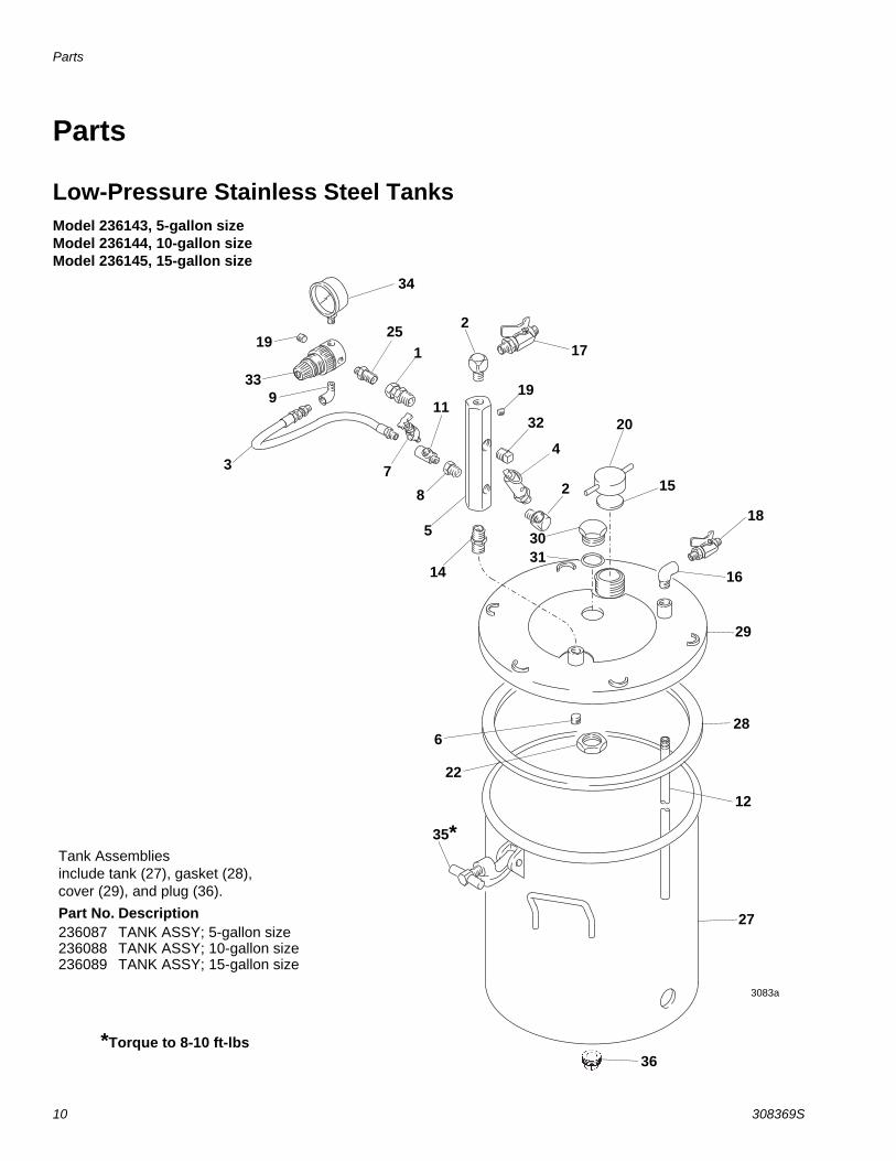
Low-Pressure Stainless Steel Tanks Model 236143, 5-gallon size Model 236144, 10-gallon size Model 236145, 15-gallon size
Tank Assembliesinclude tank (27), gasket (28), cover (29), and plug (36).Part No. Description236087 TANK ASSY; 5-gallon size236088 TANK ASSY; 10-gallon size236089 TANK ASSY; 15-gallon size
3083a
34
20
2
1
15
2517
19
4
2
12
28
29
16
32
18
14
36
35*
22
5
6
27
73
933
19
8
3130
11
*Torque to 8-10 ft-lbs

Parts
308369S 11
Low-Pressure Stainless Steel Tanks - Parts ListRef. No. Part No. Description Qty.
1 110476 ADAPTER, union, straight swivel; 3/8 npt(m) to 1/4 npsm(f)
2
2 100840 ELBOW, street; 1/4-18 npt(m x f) 23 164724 HOSE, coupled; 400 wpr;
1/8-27 npt(m) 1
4 103347 VALVE, safety, 100 psi (0.7 Mpa, 7 bar); 1/4-18 npt(m)
1
5 189016 MANIFOLD, air inlet; 3/8-18 npt; 1/4-18 npt(m)
1
6 112306 PLUG, pipe; 3/8-18 npt; sst 17 101759 FITTING, drain cock 18 100030 BUSHING;
1/8-27 npt(f) x 1/4-18 npt(m) 1
9 112307 ELBOW, street, 90°;1/8-27 npt(f) x 1/8-27 npt(m)
1
11 110475 TEE, street; zinc plated steel;1/8-27 npt(f) x 1/8-27 npt(m)
1
12 171976 TUBE; 5-gallon size; sst 1171975 TUBE; 10-gallon size; sst 1171974 TUBE; 15-gallon size; sst 1
14 156849 NIPPLE, pipe; 3/8-18 npt 115 171988 GASKET; chlororene rubber and
cork1
16 110756 ELBOW, street, 90°; 3/8 npt x 3/8 npt; sst
1
17 208390 VALVE, ball; 1/4-18 npt(m) See 307068 for parts
1
18 237533 VALVE, ball; sst; 3/8-18 npsm(m) x 3/8-18 npt(m), See 307068 for parts
1
19 100139 PLUG, pipe, headless;1/8-27 npt 220 210575 CAP, filler 1
21 176373 LABEL, Warning (not shown) 122 188784 NUT, jam; 1-1/2-12-unf-2b; sst 125 151519 NIPPLE, reducing; 1/4-1/8 npt 127 236087 TANK; 5-gallon size; sst
Includes items 28, 29 & 36 1
236088 TANK; 10-gallon size; sstIncludes items 28, 29 & 36
1
236089 TANK; 15-gallon size; sstIncludes items 28, 29 & 36
1
28 117571 GASKET; Santoprene 129 COVER, tank; sst 130 188880 PLUG, lid; sst 131 103414 O-RING, packing; polyamide 132 104813 PLUG, pipe; 3/8-18 npt 133 111501 REGULATOR; 0 to 15 psi
(0 to 0.1 MPa, 0 to 1 bar) 1
34 110444 GAUGE, pressure, air; 0 to 15 psi (0 to 0.1 MPa, 0 to 1 bar)
1
35† 110143 T-HANDLE 636 PLUG, bottom; 3/4-14 npt 138‡ LINER, antistatic polyethylene;
(not shown) 1
Keep these spare parts on hand to reduce down time
† A C-clamp replacement Kit is available. It includes the T-handle, C-clamp, pin, and cotter pin. Order 111381.
‡ To purchase a box of antistatic polyethylene lin-ers, see Accessories on page 16.
NOTE: The 307 numbers in the descriptions refer to sep-arate instruction manuals.
Ref. No. Part No. Description Qty.
Parts
12 308369S
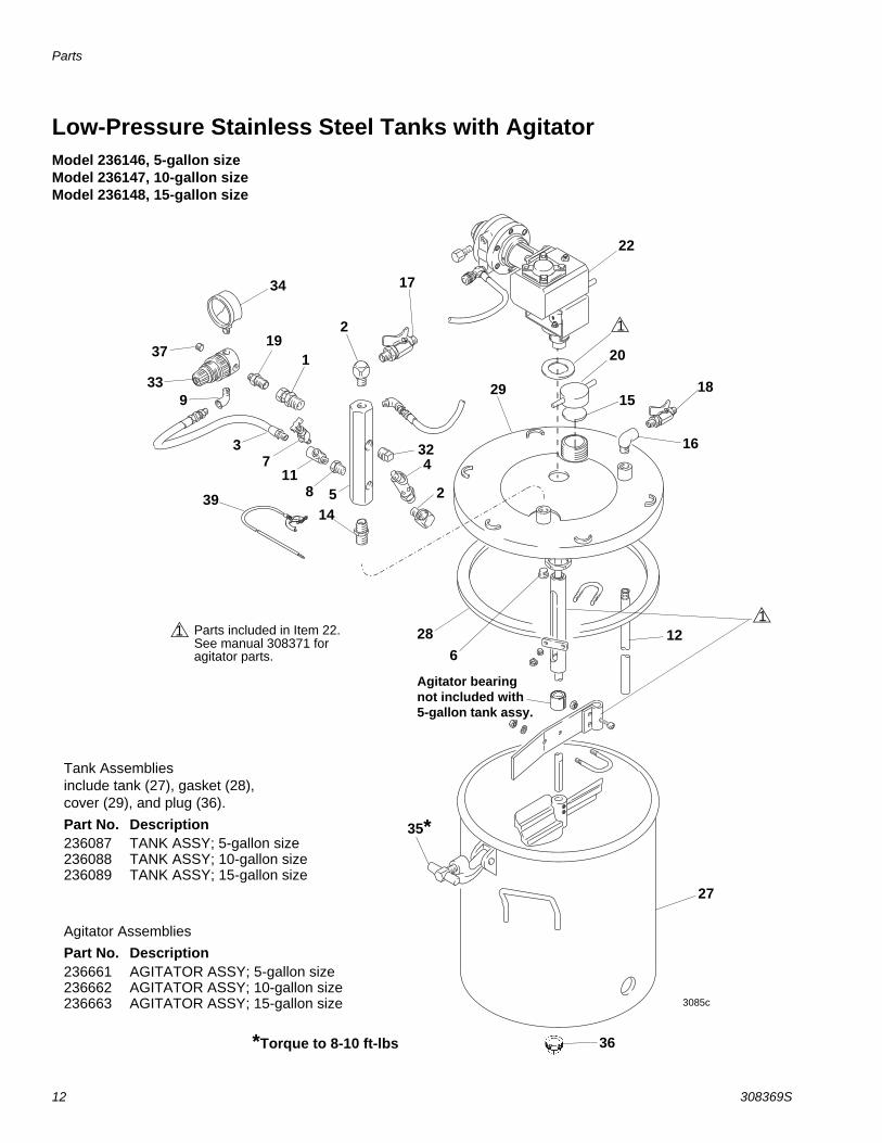
Low-Pressure Stainless Steel Tanks with AgitatorModel 236146, 5-gallon size Model 236147, 10-gallon size Model 236148, 15-gallon size
Tank Assembliesinclude tank (27), gasket (28), cover (29), and plug (36).Part No. Description236087 TANK ASSY; 5-gallon size236088 TANK ASSY; 10-gallon size236089 TANK ASSY; 15-gallon size
Agitator AssembliesPart No. Description236661 AGITATOR ASSY; 5-gallon size236662 AGITATOR ASSY; 10-gallon size236663 AGITATOR ASSY; 15-gallon size
34
29
36
35*
17
2
3085c
119
3914
58
27
117
12
163
918
1533
37 20
22
628
2
432
Agitator bearing not included with 5-gallon tank assy.
*Torque to 8-10 ft-lbs
1
Parts included in Item 22. See manual 308371 for agitator parts.
11

Parts
308369S 13
Low-Pressure Stainless Steel Tanks with Agitator - Parts ListRef. No. Part No. Description Qty.
1 110476 ADAPTER, union, straight swivel; 3/8 npt(m) to 1/4 npsm(f)
2
2 100840 ELBOW, street; 1/4-18 npt(m x f) 23 164724 HOSE, coupled; 400 wpr;
1/8-27 npt(m) 1
4 103347 VALVE, safety, 100 psi (0.7 Mpa, 7 bar); 1/4-18 npt(m)
1
5 189016 MANIFOLD, air inlet; 3/8-18 npt; 1/4-18 npt(m)
1
6 112306 PLUG, pipe; 3/8-18 npt; sst 17 101759 FITTING, drain cock 18 100030 BUSHING;
1/8-27 npt(f) x 1/4-18 npt(m) 1
9 112307 ELBOW, street, 90°;1/8-27 npt(f) x 1/8-27 npt(m)
1
11 110475 TEE, street; zinc plated steel;1/8-27 npt(f) x 1/8-27 npt(m)
1
12 171976 TUBE; 5-gallon size; sst 1171975 TUBE; 10-gallon size; sst 1171974 TUBE; 15-gallon size; sst 1
14 156849 NIPPLE, pipe; 3/8-18 npt 115 171988 GASKET; chlororene rubber and
cork1
16 110756 ELBOW, street, 90°; 3/8 npt x 3/8 npt; sst
1
17 208390 VALVE, ball; 1/4-18 npt(m) See 307068 for parts
1
18 237533 VALVE, ball; sst; 3/8-18 npsm(m) x 3/8-18 npt(m), See 307068 for parts
1
19 151519 NIPPLE, reducing; 1/4-1/8 npt 220 210575 CAP, filler 121 176373 LABEL, Warning (not shown) 1
22 236661 AGITATOR, pressure, tank; 5-gallon size; sst
1
236662 AGITATOR, pressure, tank; 10-gallon size; sst
1
236663 AGITATOR, pressure, tank; 15-gallon size; sst
1
See manual 308371 for agitator parts
27 236087 TANK; 5-gallon size; sstIncludes items 28, 29 & 36
1
236088 TANK; 10-gallon size; sstIncludes items 28, 29 & 36
1
236089 TANK; 15-gallon size; sstIncludes items 28, 29 & 36
1
28 117571 GASKET; Santoprene 129 COVER, tank; sst 132 104813 PLUG, pipe; 3/8-18 npt 133 111501 REGULATOR; 0 to 15 psi
(0 to 0.1 MPa, 0 to 1 bar) 1
34 110444 GAUGE, pressure, air; 0 to 15 psi (0 to 0.1 MPa, 0 to 1 bar)
1
35† 110143 T-HANDLE 636 PLUG, bottom; 3/4-14 npt 137 100139 PLUG, pipe, 1/8 npt 138‡ LINER, antistatic polyethylene;
(not shown) 1
39 222011 CLAMP, grounding 1
Keep these spare parts on hand to reduce down time
† A C-clamp replacement Kit is available. It includes the T-handle, C-clamp, pin, and cotter pin. Order 111381.
‡ To purchase a box of antistatic polyethylene lin-ers, see Accessories on page 16.
NOTE: The 307 numbers in the descriptions refer to sep-arate instruction manuals.
Ref. No. Part No. Description Qty.

Parts
14 308369S
High-Pressure Stainless Steel TanksModel 236149, 5-gallon size, includes items 1-38Model 236150, 10-gallon size, includes items 1-38Model 243589, 10-gallon size, includes items 2-16, 19-22, 27-32, 36-38Model 236151, 15 gallon size, includes items 1-38
1
73
19
12
58
154
20
33 2535
34
11
29
16
2
28
17
18
2
27
36*
22
6
14
329
37
Tank Assembliesinclude tank (27), gasket (28), cover (29), and plug (36).Part No. Description236087 TANK ASSY; 5-gallon size236088 TANK ASSY; 10-gallon size236089 TANK ASSY; 15-gallon size
*Torque to 8-10 ft-lbs
3031

Parts
308369S 15
High-Pressure Stainless Steel Tanks - Parts List
Ref. No. Part No. Description Qty.
1* 100361 PLUG, pipe, headless; 1/2-14 npt(f)
1
2 100840 ELBOW, street; 1/4-18 npt(m x f) 23 164724 HOSE, coupled; 400 wpr;
1/8-27 npt(m) 1
4 103347 VALVE, safety, 100 psi (0.7 Mpa, 7 bar); 1/4-18 npt(m)
1
5 189016 MANIFOLD, air inlet; 3/8-18 npt; 1/4-18 npt
1
6 112306 PLUG, pipe; 3/8-18 npt; sst 17 101759 FITTING, drain cock 18 100030 BUSHING;
1/8-27 npt(f) x 1/4-18 npt(m) 1
9 112538 ELBOW, street, 90°;1/8-27 npt(f) x 1/4-18 npt(m)
1
11 110475 TEE, street; zinc plated steel;1/8-27 npt(f) x 1/8-27 npt(m)
1
12 171976 TUBE; 5-gallon size; sst 1171975 TUBE; 10-gallon size; sst 1171974 TUBE; 15-gallon size; sst 1
14 156849 NIPPLE, pipe; 3/8-18 npt 115 171988 GASKET; chlororene rubber and
cork1
16 110756 ELBOW, street, 90°; 3/8 npt x 3/8 npt; sst
1
17* 208390 VALVE, ball; 1/4-18 npt(m) See 307068 for parts
1
18* 237533 VALVE, ball; sst; 3/8-18 npsm(m) x 3/8-18 npt(m), See 307068 for parts
1
19 100139 PLUG, pipe, headless; 1/8-27 nptf 120 210575 CAP, filler 121 176373 LABEL, Warning (not shown) 122 188784 NUT, jam; 1-1/2-12-unf-2b; sst 1
25* 155665 UNION, adapter; 3/8 npt x 3/8 npsm
1
27 236087 TANK; 5-gallon size; sstIncludes items 28, 29 & 37
1
236088 TANK; 10-gallon size; sstIncludes items 28, 29 & 37
1
236089 TANK; 15-gallon size; sstIncludes items 28, 29 & 37
1
28 117571 GASKET; Santoprene 129 COVER, tank; sst 130 188880 PLUG, lid; sst 131 103414 O-RING, packing; polyamide 132 104813 PLUG, pipe; 3/8-18 npt 133* 171937 REGULATOR; air; 2 to 125 psi
(0.01 to 0.8 MPa, 0.1 to 9 bar) 1
34* 160430 GAUGE, pressure, air; 0 to 100 psi (0 to 0.7 MPa, 0 to 7 bar)
1
35* 159239 NIPPLE, pipe, reducing; 1/2-14 npt x 3/8-18 npt
1
36† 110143 T-HANDLE 637 PLUG, bottom; 3/4-14 npt 138‡ LINER, antistatic polyethylene;
(not shown) 1
Keep these spare parts on hand to reduce down time
† A C-clamp replacement Kit is available. It includes the T-handle, C-clamp, pin, and cotter pin. Order 111381.
‡ To purchase a box of antistatic polyethylene lin-ers, see Accessories on page 16.
*Not included with Model 243589
NOTE: The 307 numbers in the descriptions refer to sep-arate instruction manuals.
Ref. No. Part No. Description Qty.

Parts
16 308369S
High-Pressure Stainless Steel Tanks with AgitatorModel 236152, 5-gallon size Model 236153, 10-gallon size Model 236154, 15-gallon size
Tank Assembliesinclude tank (27), gasket (28), cover (29), and plug (37).Part No. Description236087 TANK ASSY; 5-gallon size236088 TANK ASSY; 10-gallon size236089 TANK ASSY; 15-gallon size
Agitator AssembliesPart No. Description236661 AGITATOR ASSY; 5-gallon size236662 AGITATOR ASSY; 10-gallon size236663 AGITATOR ASSY; 15-gallon size
9
34
120
8117
3
2535
36*
14
5
172
12
2
22
33
39
32
37
1815
6
Agitator bearing
28
27
29
16
not included with 5-gallon tank assy.
3089c
4
*Torque to 8-10 ft-lbs
1
Parts included in Item 22. See manual 308371 for agitator parts.
1
1

Parts
308369S 17
High-Pressure Stainless Steel Tanks with Agitator- Parts ListRef. No. Part No. Description Qty.
1 100361 PLUG, pipe, hdless;1/2-14 npt(f) 12 100840 ELBOW, street; 1/4-18 npt(m x f) 23 164724 HOSE, coupled; 400 wpr;
1/8-27 npt(m) 1
4 103347 VALVE, safety, 100 psi (0.7 Mpa, 7 bar); 1/4-18 npt(m)
1
5 189016 MANIFOLD, air inlet; 3/8-18 npt; 1/4-18 npt(m)
1
6 112306 PLUG, pipe; 3/8-18 npt; sst 17 101759 FITTING, drain cock 18 100030 BUSHING;
1/8-27 npt(f) x 1/4-18 npt(m) 1
9 112538 ELBOW, street, 90°;1/8-27 npt(f) x 1/4-18 npt(m)
1
11 110475 TEE, street; zinc plated steel;1/8-27 npt(f) x 1/8-27 npt(m)
1
12 171976 TUBE; 5-gallon size; sst 1171975 TUBE; 10-gallon size; sst 1171974 TUBE; 15-gallon size; sst 1
14 156849 NIPPLE, pipe; 3/8-18 npt 115 171988 GASKET; chlororene rubber and
cork1
16 110756 ELBOW, street, 90°; 3/8 npt x 3/8 npt; sst
1
17 208390 VALVE, ball; 1/4-18 npt(m) See 307068 for parts
1
18 237533 VALVE, ball; sst; 3/8-18 npsm(m) x 3/8-18 npt(m), See 307068 for parts
1
19 176373 LABEL, Warning (not shown) 120 210575 CAP, filler 121 155665 UNION, adapter;
3/8 npt x 3/8 npsm 1
22 236661 AGITATOR, pressure, tank; 5-gallon size; sst
1
236662 AGITATOR, pressure, tank; 10-gallon size; sst
1
236663 AGITATOR, pressure, tank; 15-gallon size; sst
1
See manual 308371 for agitator parts
27 236087 TANK; 5-gallon size; sstIncludes items 28, 29 & 36
1
236088 TANK; 10-gallon size; sstIncludes items 28, 29 & 36
1
236089 TANK; 15-gallon size; sstIncludes items 28, 29 & 36
1
28 117571 GASKET; Santoprene 129 COVER, tank; sst 132 104813 PLUG, pipe; 3/8-18 npt 133 171937 REGULATOR. air; 2 to 125 psi
(0.01 to 0.8 MPa, 0.01 to 9 bar) 1
34 160430 GAUGE, pressure, air; 0 to 100 psi (0 to 0.7 MPa, 0 to 7 bar)
1
35 159239 NIPPLE, pipe, reducing; 1/2-14 npt x 3/8-18 npt
1
36† 110143 T-HANDLE 637 PLUG, bottom 138‡ LINER, antistatic polyethylene;
(not shown) 1
39 222011 CLAMP, grounding 1
Keep these spare parts on hand to reduce down time
† A C-clamp replacement Kit is available. It includes the T-handle, C-clamp, pin, and cotter pin. Order 111381.
‡ To purchase a box of antistatic polyethylene lin-ers, see Accessories on page 16.
NOTE: The 307 numbers in the descriptions refer to sep-arate instruction manuals.
Ref. No. Part No. Description Qty.

Accessories
18 308369S
Accessories
Strainer 202271300 psi (2.1 MPa, 21 bar) Maximum Working Pressure
Install at the tank air inlet to remove dirt and moisture from the air supply, or at the tank fluid outlet to remove particles from the paint which could clog the spray gun nozzle.
Buna-N Air Supply Hose 200 psi (1.4 MPa, 14 bar) Maximum Working Pressure
5/16” ID; cpld 1/4 npsm(f) swivel 210866 15 ft (4.6 m) long 210867 25 ft (7.6 m) long
Low-Pressure Regulator Conversion Kit 235041 15 psi (0.1 MPa, 1 bar) Working Pressure. 0 to 15 psi (0 to 0.1 MPa, 0 to 1 bar) regulated pressure range
To convert to a low-pressure regulator assembly.
High-Pressure Regulator Conversion Kit 236680 100 psi (0.7 MPa, 7 bar) Working Pressure. 0 to 100 psi (0 to 0.7 MPa, 0 to 7 bar) regulated pressure range
To convert to a high-pressure regulator assembly.
Air Regulator and Filter 202660 100 psi (0.7 MPa, 7 bar) Maximum Working Pressure
For air regulation and filtration.
Gun Air Regulator Kit 235042 100 psi (0.7 MPa, 7 bar) Working Pressure
To supply atomizing air to a spray gun from the pres-sure pot.
Nylon Fluid Supply Hose 300 psi (2.1 MPa, 21 bar) Maximum Working Pressure
3/8” ID; cpld 3/8 npsm(fbe) swivel; neoprene cover 205160 15 ft (4.6 m) long 205142 25 ft (7.6 m) long 205143 50 ft (15.2 m) long
Bottom Outlet Kit 236677 For bottom outlet fluid feeding.

Accessories
308369S 19
Standard Agitator Air Gearmotor Repair Kit 236675
For repair of worn air gear motors.
Heavy Duty Agitator To convert from a standard agitator assembly to a heavy duty agitator assembly. Recommended for fluid viscosities over 800 cp.
236661 5-gallon tank size236662 10-gallon tank size236663 15-gallon tank size
C-clamp Replacement Kit 111381 To replace the pressure tank C-clamp assembly. The kit includes the T-handle, C-clamp, pin, and cotter pin.
Antistatic Polyethylene Tank Liners Liners fit inside the tank. For ease of cleanup and maintenance.
15D059 5-gallon tank size (Quantity of 20) 15D060 10-gallon tank size (Quantity of 20) 15D061 15-gallon tank size (Quantity of 8)
Stainless Steel Agitator Paddle 186517
Material of 304 stainless steel welded construction. Replaces plastic agitator paddle 236098.
PTFE Coated Gasket 117574 Optional replacement for standard 117571 gasket.

Dimensions
20 308369S
Dimensions
3282a3190a
12.6” (320.5 mm)
5-gallon pail
tank shown
overall height
19” (483 mm)
(see chart)
without cover
14” (356 mm)
Dim. Y (see chart)
Size Model Overall Height Net Weight Paint Bucket Dim. Y
5 Gallon 236143 30.5” (775 mm) 65 lb (30 kg) 13.19” (335 mm)236149 30.5” (775 mm) 65 lb (30 kg)
236146 30.5” (775 mm) 86 lb (39 kg)236152 30.5” (775 mm) 74 lb (34 kg)
10 Gallon 236144 33.87” (860 mm) 76 lb (35 kg) 18.19” (462 mm)236150 33.87” (860 mm) 76 lb (35 kg)
236147 33.87” (860 mm) 97 lb (44 kg)236153 33.87” (860 mm) 85 lb (39 kg)
15 Gallon 236145 44.57” (1132 mm) 92 lb (42 kg) 28.94” (735 mm)236151 44.57” (1132 mm) 92 lb (42 kg)
236148 44.57” (1132 mm) 113 lb (51 kg)236154 44.57” (1132 mm) 101 lb (46 kg)

Technical Data
308369S 21
Technical DataUS Metric
Relief valve setting 100 psi 0.7 MPa, 7 barStandard agitator air consumption (continuous duty) at 60 rpm and 80 psi (0.5MPa, 5 bar) air supply pressure
15 cfm 0.42 m3/minute
Actual Tank Capacities5-gallon size 8.8 gallons 33 liters10-gallon size 12.6 gallons 48 liters15-gallon size 19.3 gallons 72 litersMaximum working pressureLow pressure regulated tank 15 psi 0.1 MPa, 1 barHigh pressure regulated tank 100 psi 0.7 MPa, 7 barInlet/Outlet SizesAir inlet size 1/4-18 npt (m)Fluid outlet size 3/8-18npsm (m)Bottom outlet size 3/4-14 npt (f)Wetted PartsModels without agitator 304 & 316 stainless steel, Santoprene, polyamide, and PETModels with agitator 304 & 316 stainless steel, Santoprene, polyamide, PET,
PTFE, and bronzeNoise (dBa)Sound power level 92 dBa @ 100 psi (0.7 MPa, 7 bar)Sound pressure level 82 dBa @ 100 psi (0.7 MPa, 7 bar)NotesSound power measured per ISO-9614-2.
Santoprene® is a registered trademark of the Monsanto Co.

All written and visual data contained in this document reflects the latest product information available at the time of publication. Graco reserves the right to make changes at any time without notice.
Original instructions. This manual contains English. MM 308369
Graco Headquarters: MinneapolisInternational Offices: Belgium, China, Japan, Korea
GRACO INC. AND SUBSIDIARIES • P.O. BOX 1441 • MINNEAPOLIS MN 55440-1441 • USA
Copyright 1994, Graco Inc. All Graco manufacturing locations are registered to ISO 9001.www.graco.com
Revision S, May, 2017
Graco Standard WarrantyGraco warrants all equipment referenced in this document which is manufactured by Graco and bearing its name to be free from defects in material and workmanship on the date of sale to the original purchaser for use. With the exception of any special, extended, or limited warranty published by Graco, Graco will, for a period of twelve months from the date of sale, repair or replace any part of the equipment determined by Graco to be defective. This warranty applies only when the equipment is installed, operated and maintained in accordance with Graco’s written recommendations.
This warranty does not cover, and Graco shall not be liable for general wear and tear, or any malfunction, damage or wear caused by faulty installation, misapplication, abrasion, corrosion, inadequate or improper maintenance, negligence, accident, tampering, or substitution of non-Graco component parts. Nor shall Graco be liable for malfunction, damage or wear caused by the incompatibility of Graco equipment with structures, accessories, equipment or materials not supplied by Graco, or the improper design, manufacture, installation, operation or maintenance of structures, accessories, equipment or materials not supplied by Graco.
This warranty is conditioned upon the prepaid return of the equipment claimed to be defective to an authorized Graco distributor for verification of the claimed defect. If the claimed defect is verified, Graco will repair or replace free of charge any defective parts. The equipment will be returned to the original purchaser transportation prepaid. If inspection of the equipment does not disclose any defect in material or workmanship, repairs will be made at a reasonable charge, which charges may include the costs of parts, labor, and transportation.
THIS WARRANTY IS EXCLUSIVE, AND IS IN LIEU OF ANY OTHER WARRANTIES, EXPRESS OR IMPLIED, INCLUDING BUT NOT LIMITED TO WARRANTY OF MERCHANTABILITY OR WARRANTY OF FITNESS FOR A PARTICULAR PURPOSE.
Graco’s sole obligation and buyer’s sole remedy for any breach of warranty shall be as set forth above. The buyer agrees that no other remedy (including, but not limited to, incidental or consequential damages for lost profits, lost sales, injury to person or property, or any other incidental or consequential loss) shall be available. Any action for breach of warranty must be brought within two (2) years of the date of sale.
GRACO MAKES NO WARRANTY, AND DISCLAIMS ALL IMPLIED WARRANTIES OF MERCHANTABILITY AND FITNESS FOR A PARTICULAR PURPOSE, IN CONNECTION WITH ACCESSORIES, EQUIPMENT, MATERIALS OR COMPONENTS SOLD BUT NOT MANUFACTURED BY GRACO. These items sold, but not manufactured by Graco (such as electric motors, switches, hose, etc.), are subject to the warranty, if any, of their manufacturer. Graco will provide purchaser with reasonable assistance in making any claim for breach of these warranties.
In no event will Graco be liable for indirect, incidental, special or consequential damages resulting from Graco supplying equipment hereunder, or the furnishing, performance, or use of any products or other goods sold hereto, whether due to a breach of contract, breach of warranty, the negligence of Graco, or otherwise.
FOR GRACO CANADA CUSTOMERSThe Parties acknowledge that they have required that the present document, as well as all documents, notices and legal proceedings entered into, given or instituted pursuant hereto or relating directly or indirectly hereto, be drawn up in English. Les parties reconnaissent avoir convenu que la rédaction du présente document sera en Anglais, ainsi que tous documents, avis et procédures judiciaires exécutés, donnés ou intentés, à la suite de ou en rapport, directement ou indirectement, avec les procédures concernées.
Graco InformationFor the latest information about Graco products, visit www.graco.com.
For patent information, see www.graco.com/patents.
TO PLACE AN ORDER, contact your Graco distributor or call to identify the nearest distributor.Phone: 612-623-6921 or Toll Free: 1-800-328-0211 Fax: 612-378-3505