
STAHL..SH SHR SHF Operating Manual
64
EN Wire Rope Hoists_ Operating and Maintenance Instructions SH SHR SHF
-
Upload
paul-jackson -
Category
Documents
-
view
1.398 -
download
179
Transcript of STAHL..SH SHR SHF Operating Manual

EN Wire Rope Hoists_Operating and Maintenance Instructions
SHSHRSHF

BASH
_02.
FM
2
Fundamental information
You have purchased a product manufactured by R. STAHL Fördertechnik GmbH.This wire rope hoist has been constructed in compliance with the applicable standards and regulations.
Inspect hoist for damage caused in transit immediately upon delivery.
Report damage caused in transit and after consulting the manufacturer/supplier repair or have repaired before installation and commissioning. Do not install or commission a damaged hoist!
- Assembly- installation- commissioning- tests- maintenance and elimination of faults
may only be carried out by a qualified person
Terms employed
UserWhoever uses and employs the wire rope hoist or has it operated by suitable trained personnel is considered to be the user (employer/company).
Trained personnelTrained personnel are persons who have been instructed and trained in the duties with which they are entrusted and the risks which may arise from incorrect behaviour, have been advised on the necessary protective devices, precautions, applicable regulations, accident prevention regulations and prevailing conditions and have proven their ability.
Skilled electricianA skilled electrician possesses knowledge and experience on electrical equipment arising from specialist training and, with knowledge of the applicable standards and regulations, is able to assess the work with which he is entrusted and detect and avoid possible risks.
Definition of a qualified person:A qualified person is one with the necessary qualification, based on theoretical and practical knowledge of hoists, for the required activities as listed in the operating instructions.The person must be in a position to assess the safety of the installation in conjunction with the application.Persons with the authority to undertake certain maintenance work on our products include STAHL service engineers and trained fitters with the corresponding certification.
Seminars: Comprehensive understanding of material handling products is a prerequisite for the correct use of equipment. Competent and practically oriented, we impart the special-ist knowledge required for the correct use, monitoring and care of your installation.Please ask for our seminar programme.
07.04
BASH
_02.
FMContents
3
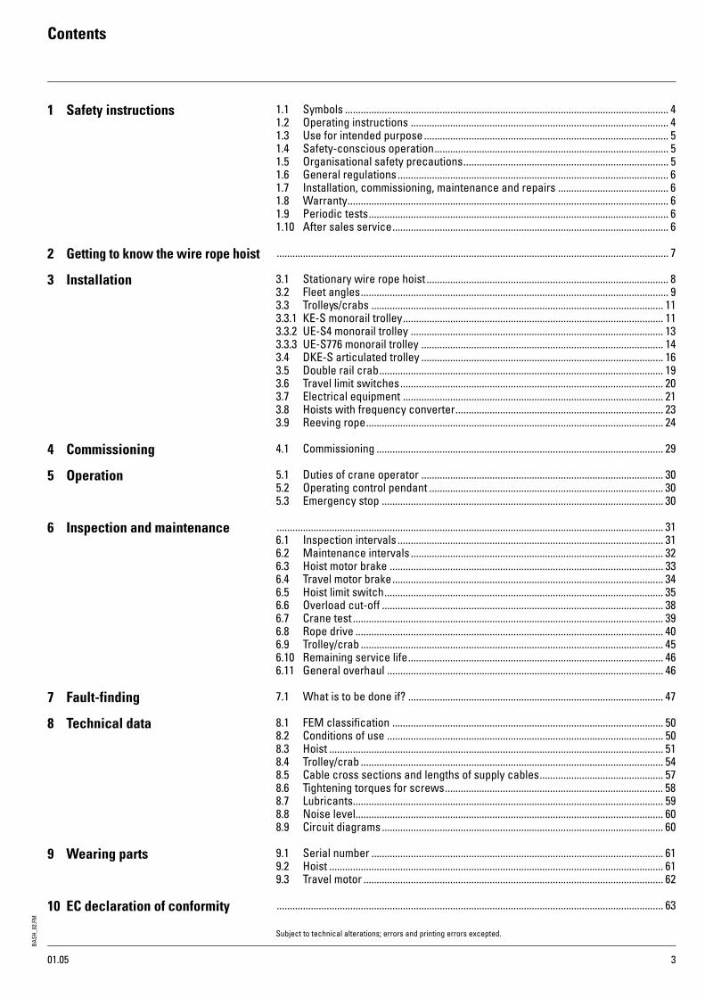
1 Safety instructions 1.1 Symbols ........................................................................................................................... 41.2 Operating instructions .................................................................................................. 41.3 Use for intended purpose ............................................................................................. 51.4 Safety-conscious operation......................................................................................... 51.5 Organisational safety precautions.............................................................................. 51.6 General regulations ....................................................................................................... 61.7 Installation, commissioning, maintenance and repairs .......................................... 61.8 Warranty.......................................................................................................................... 61.9 Periodic tests.................................................................................................................. 61.10 After sales service......................................................................................................... 6
2 Getting to know the wire rope hoist ..................................................................................................................................................... 7
3 Installation 3.1 Stationary wire rope hoist ............................................................................................ 83.2 Fleet angles..................................................................................................................... 93.3 Trolleys/crabs ............................................................................................................... 113.3.1 KE-S monorail trolley................................................................................................... 113.3.2 UE-S4 monorail trolley ................................................................................................ 133.3.3 UE-S776 monorail trolley ............................................................................................ 14 3.4 DKE-S articulated trolley ............................................................................................ 163.5 Double rail crab............................................................................................................ 193.6 Travel limit switches.................................................................................................... 203.7 Electrical equipment ................................................................................................... 213.8 Hoists with frequency converter............................................................................... 233.9 Reeving rope................................................................................................................. 24
4 Commissioning 4.1 Commissioning ............................................................................................................. 29
5 Operation 5.1 Duties of crane operator ............................................................................................ 305.2 Operating control pendant ......................................................................................... 305.3 Emergency stop ........................................................................................................... 30
6 Inspection and maintenance ................................................................................................................................................... 316.1 Inspection intervals ..................................................................................................... 316.2 Maintenance intervals ................................................................................................ 326.3 Hoist motor brake ........................................................................................................ 336.4 Travel motor brake....................................................................................................... 346.5 Hoist limit switch.......................................................................................................... 356.6 Overload cut-off ........................................................................................................... 386.7 Crane test ...................................................................................................................... 396.8 Rope drive ..................................................................................................................... 406.9 Trolley/crab ................................................................................................................... 456.10 Remaining service life................................................................................................. 466.11 General overhaul ......................................................................................................... 46
7 Fault-finding 7.1 What is to be done if? ................................................................................................. 47
8 Technical data 8.1 FEM classification ....................................................................................................... 508.2 Conditions of use ......................................................................................................... 508.3 Hoist ............................................................................................................................... 518.4 Trolley/crab ................................................................................................................... 548.5 Cable cross sections and lengths of supply cables............................................... 578.6 Tightening torques for screws................................................................................... 588.7 Lubricants...................................................................................................................... 598.8 Noise level..................................................................................................................... 608.9 Circuit diagrams........................................................................................................... 60
9 Wearing parts 9.1 Serial number ............................................................................................................... 619.2 Hoist ............................................................................................................................... 619.3 Travel motor .................................................................................................................. 62
10 EC declaration of conformity ................................................................................................................................................... 63
Subject to technical alterations; errors and printing errors excepted.
01.05

BASH
_02.
FM
1 Safety instructions
4
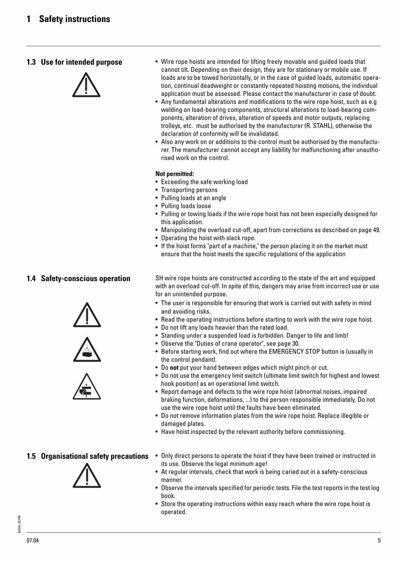
1.1 Symbols TransportThe wire rope hoist is delivered on a special pallet. This enables the hoist to be loaded and unloaded safely with a fork-lift truck. If the wire rope hoist is to be transported suspended, it must be attached by the suspension lugs provided, see sketch.
Safety at workThis symbol marks all information on safety at work where risks to life and limb are entailed.
Warning of electrical voltageCovers such as hoods and caps which are marked with this symbol may only be opened by "qualified persons or suitably instructed personnel".
Warning of suspended loadIt is forbidden for persons to stand under suspended loads. This entails risks to life and limb!
Safety in operationInformation marked with this symbol must be observed to avoid damage to the wire rope hoist or the goods transported.
1.2 Operating instructions Read carefully and observe the operating instructions.
In these operating instructions, these symbols mark particularly important infor-mation on risks and safety in operation.
07.04
BASH
_02.
FM1 Safety instructions
507.04
1.3 Use for intended purpose • Wire rope hoists are intended for lifting freely movable and guided loads that cannot tilt. Depending on their design, they are for stationary or mobile use. If loads are to be towed horizontally, or in the case of guided loads, automatic opera-tion, continual deadweight or constantly repeated hoisting motions, the individual application must be assessed. Please contact the manufacturer in case of doubt.
• Any fundamental alterations and modifications to the wire rope hoist, such as e.g welding on load-bearing components, structural alterations to load-bearing com-ponents, alteration of drives, alteration of speeds and motor outputs, replacing trolleys, etc. must be authorised by the manufacturer (R. STAHL), otherwise the declaration of conformity will be invalidated.
• Also any work on or additions to the control must be authorised by the manufactu-rer. The manufacturer cannot accept any liability for malfunctioning after unautho-rised work on the control.
Not permitted:• Exceeding the safe working load• Transporting persons• Pulling loads at an angle• Pulling loads loose• Pulling or towing loads if the wire rope hoist has not been especially designed for
this application.• Manipulating the overload cut-off, apart from corrections as described on page 49.• Operating the hoist with slack rope.• If the hoist forms "part of a machine," the person placing it on the market must
ensure that the hoist meets the specific regulations of the application
1.4 Safety-conscious operation SH wire rope hoists are constructed according to the state of the art and equipped with an overload cut-off. In spite of this, dangers may arise from incorrect use or use for an unintended purpose. • The user is responsible for ensuring that work is carried out with safety in mind
and avoiding risks. • Read the operating instructions before starting to work with the wire rope hoist.• Do not lift any loads heavier than the rated load.• Standing under a suspended load is forbidden. Danger to life and limb!• Observe the "Duties of crane operator", see page 30.• Before starting work, find out where the EMERGENCY STOP button is (usually in
the control pendant).• Do not put your hand between edges which might pinch or cut.• Do not use the emergency limit switch (ultimate limit switch for highest and lowest
hook position) as an operational limit switch.• Report damage and defects to the wire rope hoist (abnormal noises, impaired
braking function, deformations, ...) to the person responsible immediately. Do not use the wire rope hoist until the faults have been eliminated.
• Do not remove information plates from the wire rope hoist. Replace illegible or damaged plates.
• Have hoist inspected by the relevant authority before commissioning.
1.5 Organisational safety precautions • Only direct persons to operate the hoist if they have been trained or instructed in its use. Observe the legal minimum age!
• At regular intervals, check that work is being caried out in a safety-conscious manner.
• Observe the intervals specified for periodic tests. File the test reports in the test log book.
• Store the operating instructions within easy reach where the wire rope hoist is operated.

BASH
_02.
FM
1 Safety instructions
6
1.6 General regulations • Safety regulations and accident prevention regulations.• National regulations
1.7 Installation, commissioning,maintenance and repairs
• Installation, commissioning, maintenance and repairs may be carried out by quali-fied persons only, see page 2.
• We recommend having installation carried out by personnel engaged by the manufacturer (R. STAHL).
• Do not carry out any alterations or modifications.• Additional fitments must be approved by the manufacturer (R. STAHL).
(During welding work, electrode and ground must be in contact with the same component!)
• Use only original spare parts for repairs.
If the wire rope hoist is constantly operated out of doors and exposed to the elements without protection, we recommend fitting a small roof or at least "parking" the hoist under a roof.
1.8 Warranty • The warranty will become invalid if these operating instructions are not observed for installation, operation, inspection and maintenance.
• Repairs and elimination of faults within the scope of the warranty may only be per-formed by qualified personnel (see page 2) after the manufacturer/supplier has been consulted and has given his approval.The warranty will become invalid if the hoist is modified or original spare parts not used.
1.9 Periodic tests Hoists and cranes must be inspected by a qualified person see page 2 at least once a year. The results of the test must be recorded and filed in the test log book.The remaining service life of the hoist acc. to FEM 9.755 must also be established during this inspection.The periodic tests must be adapted to the hoist’s use. Intensive use entails shorter maintenance intervals.
All tests must be initiated by the user, see page 2.
1.10After sales service With the purchase of this wire rope hoist, you have decided on a high-quality piece of lifting equipment. R. STAHL’s after sales service will give you advice on its correct use.
In order to maintain the safety and constant availability of your wire rope hoist, we recommend concluding a maintenance agreement on the basis of which we will undertake the "periodic tests" on your behalf.
Repairs will be carried out professionally and quickly by our trained personnel.
07.04
BASH
_02.
FM2 Getting to know the wire rope hoist
7
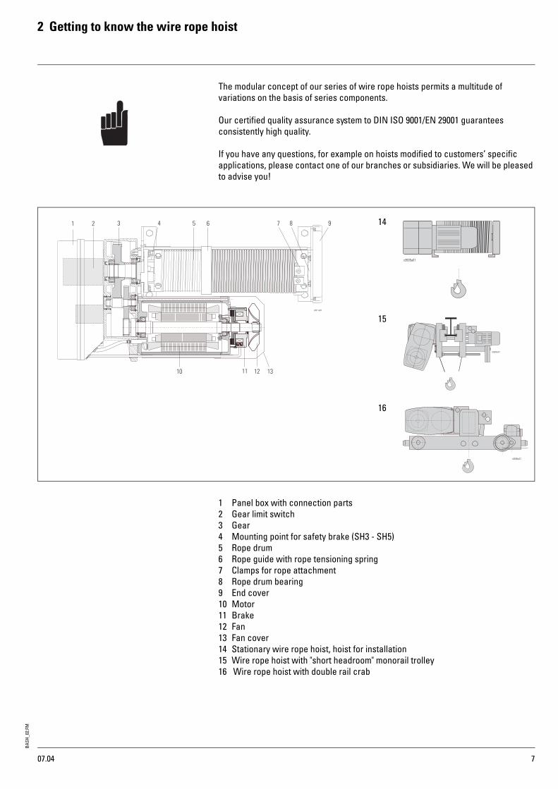
The modular concept of our series of wire rope hoists permits a multitude of variations on the basis of series components.
Our certified quality assurance system to DIN ISO 9001/EN 29001 guarantees consistently high quality.
If you have any questions, for example on hoists modified to customers’ specific applications, please contact one of our branches or subsidiaries. We will be pleased to advise you!
1 Panel box with connection parts2 Gear limit switch3 Gear4 Mounting point for safety brake (SH3 - SH5)5 Rope drum6 Rope guide with rope tensioning spring7 Clamps for rope attachment8 Rope drum bearing9 End cover10 Motor11 Brake12 Fan13 Fan cover14 Stationary wire rope hoist, hoist for installation15 Wire rope hoist with "short headroom" monorail trolley16 Wire rope hoist with double rail crab
14
15
16
07.04
BASH
_02.
FM
3 Installation
8
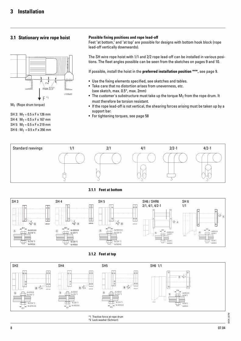
3.1 Stationary wire rope hoist Possible fixing positions and rope lead-offFeet "at bottom," and "at top" are possible for designs with bottom hook block (rope lead-off vertically downwards).
The SH wire rope hoist with 1/1 and 2/2 rope lead-off can be installed in various posi-tions. The fleet angles possible can be seen from the sketches on pages 9 and 10.
If possible, install the hoist in the preferred installation position ***, see page 9.
• Use the fixing elements specified, see sketches and tables.• Take care that no distortion arises from unevenness, etc.
(see sketch, max. 0.5°, max. 2mm)• The customer's substructure must take up the torque MT from the rope drum. It
must therefore be torsion resistant. • If the rope lead-off is not vertical, the shearing forces arising must be taken up by a
support bar.• For tightening torques, see page 58
3.1.1 Feet at bottom
3.1.2 Feet at top
MT (Rope drum torque)
SH 3: MT = 0.5 x F x 126 mmSH 4: MT = 0.5 x F x 167 mmSH 5: MT = 0.5 x F x 219 mmSH 6 : MT = 0.5 x F x 356 mm
Standard reevings 1/1 2/1 4/1 4/2-12/2-1
SH 3 SH 4 SH 5 SH6 / SHR6 SH 6 2/1, 4/1, 4/2-1 1/1
SH3 SH4 SH5 SH6 1/1
*1 Tractive force at rope drum*2 Lock washer (Schnorr)
07.04

BASH
_02.
FM3 Installation
9
3.2 Fleet angles
3.2.1 Feet at bottom
3.2.2 Feet at top
1/1, 2/2
SH 3 SH 4 SH5 SH6α1 4° 5° 8° 8°α2 23° 13° 20° 18°α3 27° 30° 30° 30°α4 74° 73° 76° 80°α5 30° 30° 30° 25°α6 113° 103° 110° 108°α7 83° 81° 60° 60°α8 11 12° 18° 20°α9 24° 26° 30° 12°α10 7° 7° 8° 8°α12 90° 90° 90° -
SH 3SH 4SH 5SH 6
1/1, 2/2
SH 3 SH 4 SH 5 SH 6α1 4° 5° 8° 8°α2 23° 13° 20° 18°α3 27° 30° 30° 12°α4 74° 73° 76° 80°α5 16° 17° 14° -α6 34° 32° 36° -α7 74° 73° 76° -α12 90° 90° 90° 8°α13 90° 90° 90° 30°
SH 3SH 4 SH 5 SH 6
*** Preferred installation position*1 Standard*2 By turning rope guide*4 By turning rope guide and grease pan; version G, H not possible for SH 6
07.04

BASH
_02.
FM
3 Installation
10
3.2.3 Fleet angles
The rope guide must be adjusted to the fleet angle. Observe also the radial rope exit angle γ.
3.2.4 Angles of installation
• Instal the wire rope hoist within the permissible range of angles. Hoists with rope drives with bottom hook blocks must always be installed horizontal to their longitudinal axis.
• The max. permissible rope exit angle acc. to standard is 4° for non-twist-free wire ropes, 1.5° for twist-free wire ropes. However even at these angles a reduction in service life is to be expected.
• The wire rope must not touch the rope guide or structural elements.
Type
γ
SH 3 53°SH 4 60°SH 5 53°SH 6 53°
γ°
07.04

BASH
_02.
FM3 Installation
11
3.3 Trolleys/crabs3.3.1 Monorail trolley (KE-S33 - 76) with SH 3, SH 4, SH 5, SHR 6, SH 6 wire rope hoists
• Check flange width "B" and clearance "c" against table 1 and set trolley to beam width if necessary.Caution! If the flange width is altered (by customer), it may be necessary to alter the counterweight to prevent the trolley canting. Please have it checked by our after-sales service.
Installation if end of runway is freely accessible• Slide trolley onto end of runway and check play f/2.
Installation if end of runway is not accessible• Unscrew nuts (2) on threaded bolts (1) and slide trolley side cheek (3) outwards by
approx. "x" mm or until dimension "B+y" is reached.• Push hoist side of trolley onto lower flange of runway beam and secure against
slipping.• Push trolley side cheek (3) towards the runway beam on support bolt (4).• Adjust dimension "c" with nuts (2), tighten nuts (2).• Check track gauge "c" and play "f/2". • Tighten nuts (2) with torque spanner. • For tightening torques see table 1.
Drive shaft for travel drive (trolleys KE-S33 - KE-S65)
• Fit drive shaft in mounting position X3 or X4 depending on flange width (B) of runway beam and length (L) of drive shaft (D).
• Fit circlips (S). • See sketch and table 2.
Table 1
HoistØD
Trolleyc f/2 x y
mm INP IPE IPB " mm NmSH 3 80 KE-S33
B= 90...500B+67*1 1.5 70 137 210
SH 4 100 KE-S44 B+67*1 1.5 80 147 210SH 5 140 KE-S65 B= 119...500 B+67*1 1.5 95 162 210
SHR 6, SH 6 200 KE-S76 B= 124...500 B+92*1 1.5 95 187 210
Table 2ØD
[mm]B
[mm]Drive shaft
L [mm] Position
80100
90 - 145390
X3 -146 - 195 - X4196 - 250
495X3 -
251 - 306 - X4301 - 350
595X3 -
351 - 399 - X4400 - 450
695X3 -
451 - 500 - X4
140
119 - 145505
X3 -146 - 200 - X4201 - 250
505X3 -
251 - 305 - X4330 - 400
710X3 -
401 - 500 - X4
200124 - 220 510
see page 12221 - 500 780
Table 3ØD
[mm]L3 ±2[mm]
L4 ±2[mm]
80100 96.4 46.4
140 124.6 46.4
*1 with INP beam: -2 mm
07.04
BASH
_02.
FM
3 Installation
12
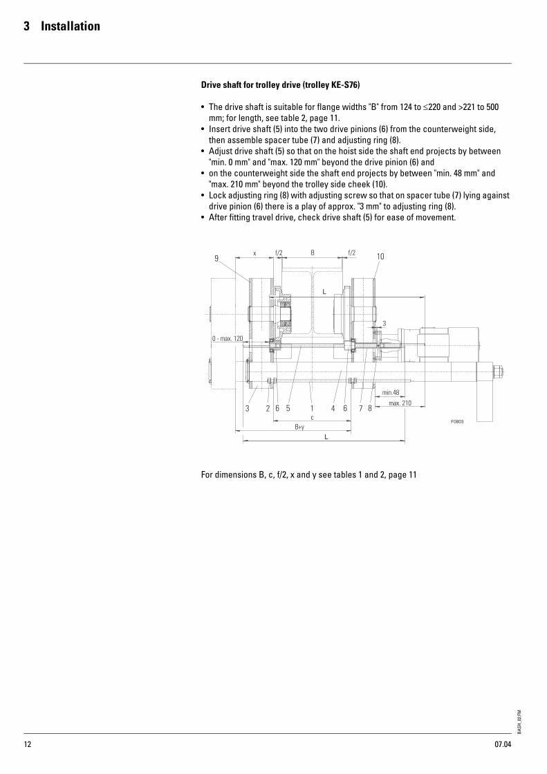
Drive shaft for trolley drive (trolley KE-S76)
• The drive shaft is suitable for flange widths "B" from 124 to ≤220 and >221 to 500 mm; for length, see table 2, page 11.
• Insert drive shaft (5) into the two drive pinions (6) from the counterweight side, then assemble spacer tube (7) and adjusting ring (8).
• Adjust drive shaft (5) so that on the hoist side the shaft end projects by between "min. 0 mm" and "max. 120 mm" beyond the drive pinion (6) and
• on the counterweight side the shaft end projects by between "min. 48 mm" and "max. 210 mm" beyond the trolley side cheek (10).
• Lock adjusting ring (8) with adjusting screw so that on spacer tube (7) lying against drive pinion (6) there is a play of approx. "3 mm" to adjusting ring (8).
• After fitting travel drive, check drive shaft (5) for ease of movement.
For dimensions B, c, f/2, x and y see tables 1 and 2, page 11
07.04
BASH
_02.
FM3 Installation
13
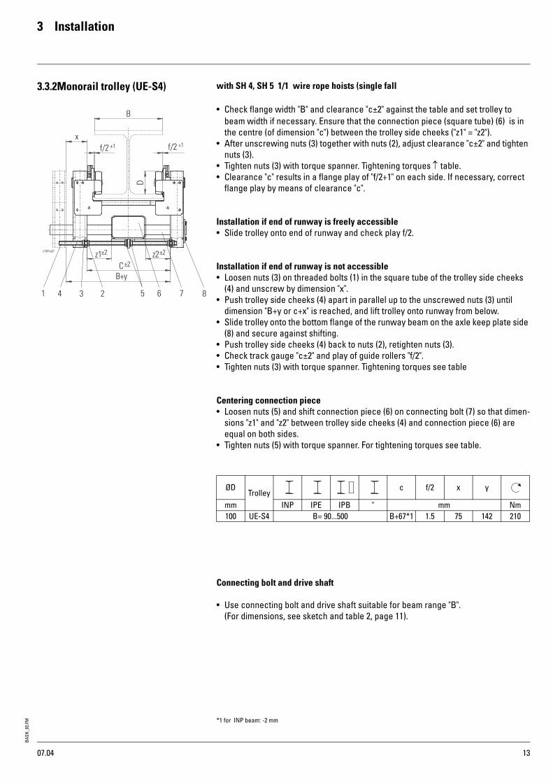
3.3.2Monorail trolley (UE-S4) with SH 4, SH 5 1/1 wire rope hoists (single fall
• Check flange width "B" and clearance "c±2" against the table and set trolley to beam width if necessary. Ensure that the connection piece (square tube) (6) is in the centre (of dimension "c") between the trolley side cheeks ("z1" = "z2").
• After unscrewing nuts (3) together with nuts (2), adjust clearance "c±2" and tighten nuts (3).
• Tighten nuts (3) with torque spanner. Tightening torques ↑ table.• Clearance "c" results in a flange play of "f/2+1" on each side. If necessary, correct
flange play by means of clearance "c".
Installation if end of runway is freely accessible• Slide trolley onto end of runway and check play f/2.
Installation if end of runway is not accessible• Loosen nuts (3) on threaded bolts (1) in the square tube of the trolley side cheeks
(4) and unscrew by dimension "x".• Push trolley side cheeks (4) apart in parallel up to the unscrewed nuts (3) until
dimension "B+y or c+x" is reached, and lift trolley onto runway from below.• Slide trolley onto the bottom flange of the runway beam on the axle keep plate side
(8) and secure against shifting.• Push trolley side cheeks (4) back to nuts (2), retighten nuts (3).• Check track gauge "c±2" and play of guide rollers "f/2".• Tighten nuts (3) with torque spanner. Tightening torques see table
Centering connection piece• Loosen nuts (5) and shift connection piece (6) on connecting bolt (7) so that dimen-
sions "z1" and "z2" between trolley side cheeks (4) and connection piece (6) are equal on both sides.
• Tighten nuts (5) with torque spanner. For tightening torques see table.
Connecting bolt and drive shaft
• Use connecting bolt and drive shaft suitable for beam range "B".(For dimensions, see sketch and table 2, page 11).
ØDTrolley
c f/2 x y
mm INP IPE IPB " mm Nm100 UE-S4 B= 90...500 B+67*1 1.5 75 142 210
*1 for INP beam: -2 mm
07.04

BASH
_02.
FM
3 Installation
14
3.3.3Monorail trolley (UE-S776) with SH 6, 4/1 wire rope hoists (four-fall)
• Check flange width "B" and clearance "c±2" against the table and set trolley to beam width if necessary. Ensure that the connection piece (square tube) (6) is in the centre (of dimension "c") between the trolley side cheeks ("z1" = "z2").
• After unscrewing nuts (3) together with nuts (2), adjust clearance "c±2" and tighten nuts (3).
• Do not distort plate (10)! Tighten nuts (5) lightly and then unscrew by a quarter turn. Lock nuts 9 against nuts 5 with a torque spanner. See table for tightening torques.
• Tighten nuts (3) with torque spanner. See table for tightening torques.• Clearance "c" results in a flange play of "f/2+1" on each side. If necessary, correct
flange play by means of clearance "c".
Installation if end of runway is freely accessible• Slide trolley onto end of runway and check play f/2.
Installation if end of runway is not accessible• Loosen nuts (3) on threaded bolts (1) in the square tube of the trolley side cheeks
(4) and unscrew by dimension "x".• Push trolley side cheeks (4) apart in parallel up to the unscrewed nuts (3) until
dimension "B+y or c+x" is reached, and lift trolley onto runway from below.• Slide trolley onto the bottom flange of the runway beam on the axle keep plate side
(8) and secure against shifting.• Push trolley side cheeks (4) back to nuts (2), retighten nuts (3).• Check track gauge "c±2" and play of guide rollers "f/2".• Tighten nuts (3) with torque spanner. For tightening torques, see table
Centering connection piece• Loosen nuts (5) and shift connection piece (6) on connecting bolt (7) so that dimen-
sions "z1" and "z2" between trolley side cheeks (4) and connection piece (6) are equal on both sides.
• Tighten nuts (5) with torque spanner. For tightening torques see table.•
Connecting bolt and drive shaft
• Use connecting bolt and drive shaft suitable for beam range "B".(For dimensions, see sketch on page 15).
ØDTrolley
c f/2 x y
mm INP IPE IPB " mm Nm200 UE-S776 B= 200....500 B+92 1.5 95 187 210
07.04
BASH
_02.
FM3 Installation
15
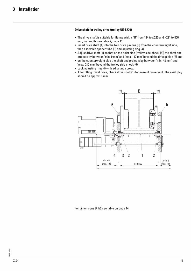
Drive shaft for trolley drive (trolley UE-S776)
• The drive shaft is suitable for flange widths "B" from 124 to ≤220 and >221 to 500 mm; for length, see table 2, page 11.
• Insert drive shaft (1) into the two drive pinions (6) from the counterweight side, then assemble spacer tube (3) and adjusting ring (4).
• Adjust drive shaft (1) so that on the hoist side [trolley side cheek (5)] the shaft end projects by between "min. 9 mm" and "max. 117 mm" beyond the drive pinion (2) and
• on the counterweight side the shaft end projects by between "min. 48 mm" and "max. 210 mm" beyond the trolley side cheek (6).
• Lock adjusting ring (4) with adjusting screw.• After fitting travel drive, check drive shaft (1) for ease of movement. The axial play
should be approx. 3 mm.
For dimensions B, f/2 see table on page 14
W0786
3 22 14
5
B
min. 9max. 117
min. 48max. 120 c= B+92
L
6
07.04

BASH
_02.
FM
3 Installation
16
3.4 Articulated trolley (DKE-S4 / DKE-S6)
with SH 3, SH 4, SH 5 wire rope hoists
• Check flange width "B" and clearance "c" against the table and set trolley to beam width if necessary. Ensure that the connection piece (square tube) (6) is in the centre (of dimension "c") between the trolley side cheeks ("z1" = "z2").
• After unscrewing nuts (3) together with nuts (2), adjust clearance "c" and tighten nuts (3).
• Tighten nuts (3) with torque spanner. • See table for tightening torques.• Clearance "c" results in a flange play of "f/2" on each side. If necessary, correct
flange play by means of clearance "c".
Installation if end of runway is freely accessible• Slide trolley onto end of runway.
Installation if end of runway is not accessible• Loosen nuts (3) on threaded bolts (1) in the square tube of the trolley side cheeks
(4) and unscrew by dimension "x".• Push trolley side cheeks (4) apart in parallel up to the unscrewed nuts (3) until
dimension "B+y or c+x" is reached, and lift trolley onto runway from below.• Lift trolley onto runway from below.• Slide trolley onto the bottom flange of the runway beam on the hoist side and
secure against shifting.• Push trolley side cheeks (4) back to nuts (2), retighten nuts (3).• Check track gauge "c" and play of guide rollers "f/2".• Tighten nuts (3) with torque spanner. • See table for tightening torques.
Centering bogie• Loosen nuts (5) and shift bogie (6) on connecting bolt (7).• Dimension "z" between trolley side cheeks (4) and bogie (6) is equal on both sides.• Tighten nuts (5) with torque spanner. • For tightening torques see table.
Hoist ØD Trolley B f/2 c x y Nut (3) Nut (5)
[mm] [mm] [Nm]SH 3SH 4
100 DKE-S 4 90 - 220 1.5 B+80 67 147 215 85
SH 5 140 DKE-S 6 119 - 300 1.5 B+84 75 159 215 85
07.04
BASH
_02.
FM3 Installation
17
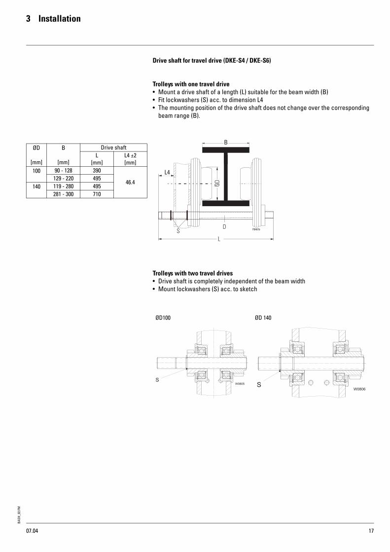
Drive shaft for travel drive (DKE-S4 / DKE-S6)
Trolleys with one travel drive• Mount a drive shaft of a length (L) suitable for the beam width (B)• Fit lockwashers (S) acc. to dimension L4• The mounting position of the drive shaft does not change over the corresponding
beam range (B).
Trolleys with two travel drives• Drive shaft is completely independent of the beam width• Mount lockwashers (S) acc. to sketch
ØD
[mm]
B
[mm]
Drive shaftL
[mm]L4 ±2[mm]
100 90 - 128 390
46.4129 - 220 495
140 119 - 280 495281 - 300 710
ØD100 ØD 140
07.04
BASH
_02.
FM
3 Installation
18
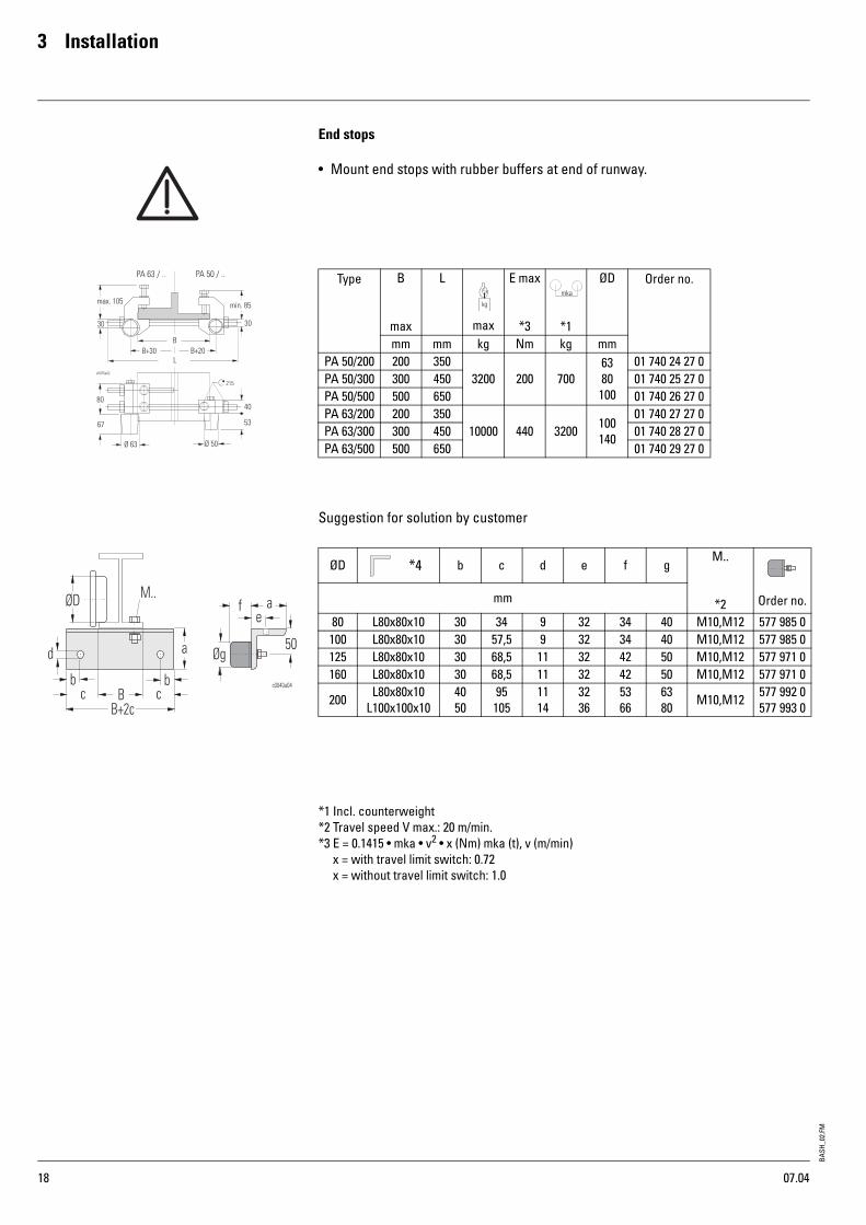
End stops
• Mount end stops with rubber buffers at end of runway.
Suggestion for solution by customer
*1 Incl. counterweight*2 Travel speed V max.: 20 m/min.*3 E = 0.1415 • mka • v2 • x (Nm) mka (t), v (m/min) x = with travel limit switch: 0.72 x = without travel limit switch: 1.0
Type B
max
L
max
E max
*3 *1
ØD Order no.
mm mm kg Nm kg mmPA 50/200 200 350
3200 200 7006380100
01 740 24 27 0PA 50/300 300 450 01 740 25 27 0PA 50/500 500 650 01 740 26 27 0PA 63/200 200 350
10000 440 3200 100140
01 740 27 27 0PA 63/300 300 450 01 740 28 27 0PA 63/500 500 650 01 740 29 27 0
ØD b c d e f gM..
*2 Order no.mm
80 L80x80x10 30 34 9 32 34 40 M10,M12 577 985 0100 L80x80x10 30 57,5 9 32 34 40 M10,M12 577 985 0125 L80x80x10 30 68,5 11 32 42 50 M10,M12 577 971 0160 L80x80x10 30 68,5 11 32 42 50 M10,M12 577 971 0
200 L80x80x10L100x100x10
4050
95105
1114
3236
5366
6380 M10,M12 577 992 0
577 993 0
*4
07.04

BASH
_02.
FM3 Installation
19
3.5 Double rail crab (OE-S ) • Check track gauge Spw on crab and rail.• L1 max - L1 min = 5 mm, see sketch.• Check lateral play between rail and flange, see sketch.• Bolt rubber buffers to crab or runway end stop.• Fit suitable stops. For dimensions see sketch and table.• Remove transport anchor screw TS (only on crabs with wheel Ø 125).• The runway must meet the requirements of DIN 4132.• The rail joints must be even on both running and guide surfaces; grind down if
necessary.
S as per table if crab is positioned symmetrically on runway. If asymmetrically, Sleft + Sright = 2 x S
End stops
Ø100ø D S100 2.5-5125 2.5-5160 3.5-6200 4.5-7
Crane
Ø125 - Ø200
Crane
ø D h100 45125 97160 100200 100
07.04

BASH
_02.
FM
3 Installation
20
3.6 Travel limit switch 3.6.1 Monorail trolley
The travel limit switches (optional) are mounted on the trolley.
3.6.2 Double rail crab
The travel limit switch assembly is supplied ready-wired but not mounted and must be secured to the towing arm for the power supply.
The switching contacts are designed for control current.
Switching functions:1. Limit switching in both directions of travel (2 switches). 2. Pre-switching and limit switching in both directions of travel (3 switches).
The speed is switched over from "fast" to "slow" before the end of the runway is reached, and is cut off at the end of the runway.
X = stop, leftY = stop, rightZ = fast / slow
Monorail trolley Double rail crab
TypeH C
[mm]OE-S 04 77 795OE-S 05 85 915OE-S 06 87 915OE-S 07 107 915
07.04
*1 Switch activator by customer

BASH
_02.
FM3 Installation
21
3.7 Electrical equipment For the sake of safety, have the wire rope hoist connected by a skilled electrician (see page 2). Observe the relevant safety and accident prevention regulations!
3.7.1 Supply cables• As fixed installed cables:
NYY, NYM• As flexible cables:
H07RN-F or NGFLGöu, or equivalent cables.• See page 57 for minimum cross-section and max. length of supply cable.
3.7.2 Terminals• Check that all terminals are firmly attached.
3.7.3 Fusing• NEOZED, DIAZED or NH fuses in operating class gL/gG, see page 51.• Observe the correct fuse sizes so that the crane switch contacts do not weld if
there is a short circuit and overload protection of lead is ensured!
3.7.4 EMERGENCY STOPIt must be possible to disconnect the system electrically from the operating position. This function can be provided by:• EMERGENCY STOP button in the control pendant in conjunction with the crane
switch contactor,• main isolator, if this is directly accessible and positioned close to the operating
position.
3.7.5 Main isolator• must disconnect the wire rope hoist on all poles,• must be lockable in OFF position,• must be installed in an easily accessible place in the system,• must be marked as such to avoid mistakes.
3.7.6 Disconnecting switch• is necessary if more than one floor-operated hoist is supplied with power,• must be lockable in OFF position.
3.7.7 Electromagnetic compatibility
No particular protective measures are taken on electric wire rope hoists with control by customer or crane manufacturer’s control. In order to comply with the require-ments of EN 55014-1, suitable precautions must be taken by the customer.In order to achieve an optimum result with minimum effort, we recommend using our FEM1 radio interference suppression module for the SH wire rope hoist.Order no. 578 525 0 ≤ 415V.Order no. 578 526 0 ≤ 800V.Clip the module onto the tophat rail and connect to the mains supply cable.
07.04

BASH
_02.
FM
3 Installation
22
3.7.8 Overload cut-offDescription of system• prevents an overload being lifted. If an overload has been established, the load can
only be lowered. The switch is set in the factory. Corrections are only permissible in special cases, see page 49.In certain applications, wire rope hoists may also be used without an overload cut-off. However in this case they do not meet the requirements of the EU directives and are not marked with the CE symbol.
Load measurement at rope anchorage
With LMS mechanical sensor
The overload cut-off is set to rated load +15%.
With LET electronic sensor
The overload cut-off is set to rated load +10%.
Load measurement at gear
With LEI electronic sensor
The overload cut-off is set to rated load +10%.Remove the transport anchor screws marked in red after installation and before commissioning.
W0787
W0788
07.04

BASH
_02.
FM3 Installation
23
3.7.9 Connecting to mains
• Compare existing mains voltage and frequency with the information on the rating plate.
• Route cables into the hoist connection box through the cable glands.• Connect according to the circuit diagrams supplied.
Measure control voltage. If the measured value exceeds the rated control voltage by more than 10%, a different tapping point must be selected on the primary side of the control transformer.
• Do not connect any live lead to the temperature sensors! Damaged temperature sensors cannot protect the motor.
• Check that the direction of rotation of the rope drum corresponds to the symbols on the control pendant : Press "slow up" button on control pendant. Never press down button first! If the hook moves upwards or does not move because the limit switch has disconnected in top hook position, the phase connection is correct.
• Crosscheck by pressing "slow down" button on control pendant.If the movement of the hook does not correspond to the symbols on the control pendant, interchange two phase conductors of the supply cable.
Caution! Risk of accident! If this is not observed, serious accidents or damage to the hoist may occur!
Controls by others
• If the controls are supplied by others, connect the temperature sensors of the hoist motor, the hoist brake, the overload cut-off and the emergency hoist limit switch according to our connection diagrams.
• Do not connect any live lead to the temperature sensors! Damaged temperature sensors cannot protect the motor.
• Construct the control according to the circuit diagrams supplied.• The declaration of conformity is valid only for the scope supplied by the manufac-
turer.
3.8 SHF hoists with frequency inverter • See concise operating instructions HOISTING - TRAVEL (Siemens)
07.04

BASH
_02.
FM
3 Installation
24
3.9 Reeving rope The wire rope is wound onto the drum in the factory. If not, see page 40, "Replacing wire rope".If the bottom hook block is not fitted, proceed as follows:
• Gripper pliers hold the rope securely.
• The wire rope hoist must be switched on in order to reeve the rope. All work must therefore be carried out with extreme care: for your safety and for troublefree functioning of the wire rope hoist!
1. Lay out the end of the rope not wound on the drum, or let it hang freely.
2. Check that the wire rope lies snugly on the rope drum, tighten if necessary. Avoid slack rope on the drum! Slack rope can destroy the rope guide and the wire rope.
3. Colour code the beginning of the rope on one side.
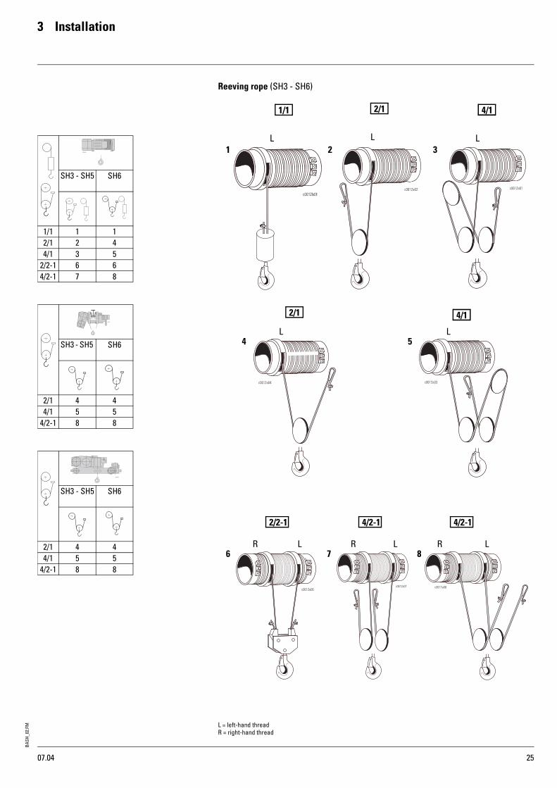
4. Reeve the end of the rope into the rope sheave(s) of the bottom hook block and return pulley(s), see page 25. Do not twist the rope; the colour coding facilitates checking.
5. Fasten the end of the rope in the rope anchorage, see page 25 (1-8).
6. Perform several runs over the full height of lift without load.
7. Repeat with increasing loads.
8. Make any twisting in the rope witch may occur visible by sticking on a paper tag. Severe twisting is shown by the bottom hook block's turning, especially when not under load.
9. If any twisting should occur, remove the wire rope and untwist by letting it hang freely or laying it out. Twisting in the wire rope prejudices safety and service life.
Any twisting should therefore be removed before subjecting the hoist to any further load. The rope could otherwise be permanently distorted and might have to be replaced!
07.04
BASH
_02.
FM3 Installation
25
Reeving rope (SH3 - SH6)
SH3 - SH5
SH6
1/1 1 12/1 2 44/1 3 5
2/2-1 6 64/2-1 7 8
SH3 - SH5 SH6
2/1 4 44/1 5 5
4/2-1 8 8
SH3 - SH5
SH6
2/1 4 44/1 5 5
4/2-1 8 8
1 3L L
2L
4 5L L
6 7 8L R L R LR
2/1 1/1 4/1 4/1
2/2-1 4/2-1 4/2-1
L = left-hand threadR = right-hand thread
07.04
1/1 2/1 1/1 4/1 4/1
BASH
_02.
FM
3 Installation
26
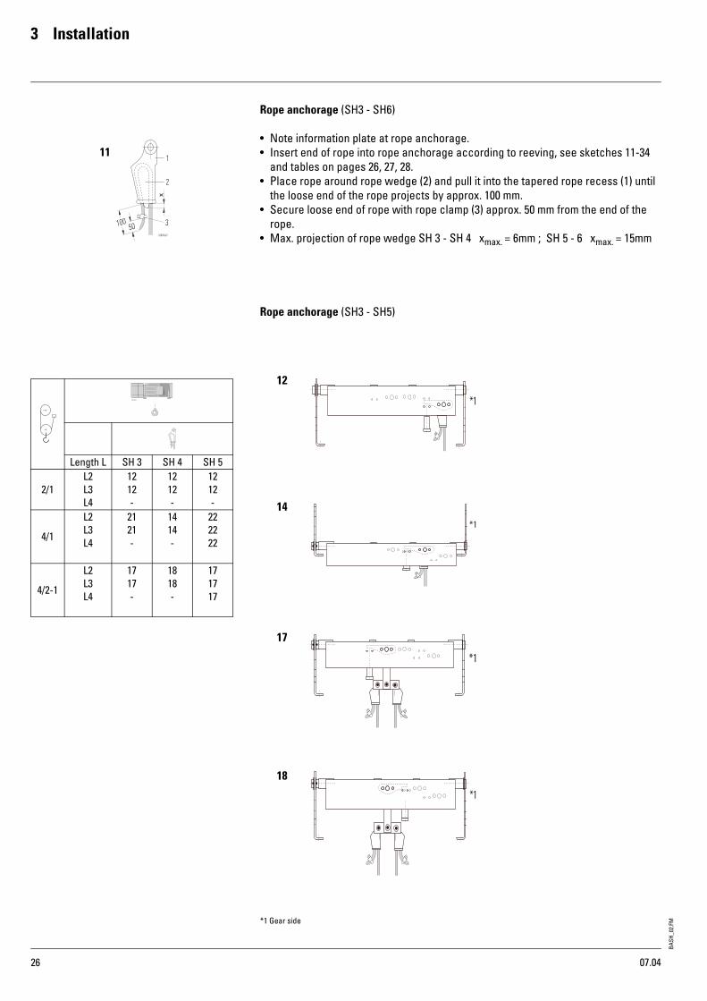
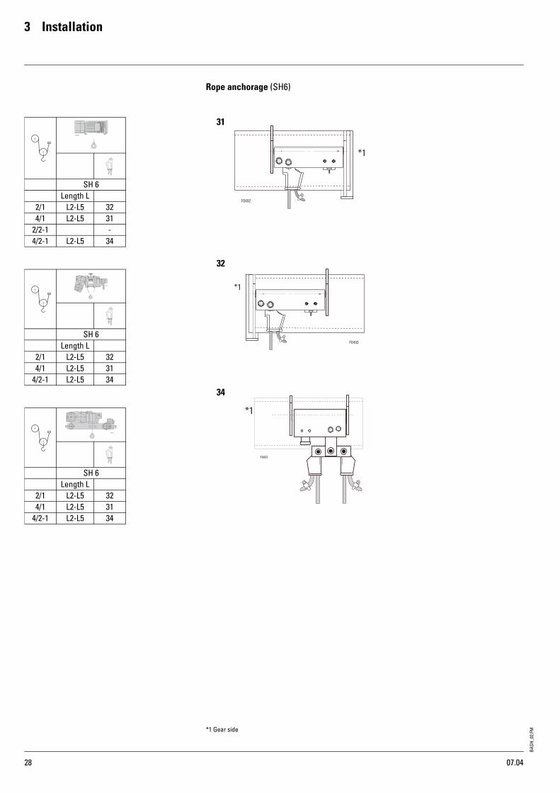
Rope anchorage (SH3 - SH6)
• Note information plate at rope anchorage.• Insert end of rope into rope anchorage according to reeving, see sketches 11-34
and tables on pages 26, 27, 28.• Place rope around rope wedge (2) and pull it into the tapered rope recess (1) until
the loose end of the rope projects by approx. 100 mm.• Secure loose end of rope with rope clamp (3) approx. 50 mm from the end of the
rope.• Max. projection of rope wedge SH 3 - SH 4 xmax. = 6mm ; SH 5 - 6 xmax. = 15mm
Rope anchorage (SH3 - SH5)
11
12
14
18
17
Length L SH 3 SH 4 SH 5
2/1L2L3L4
1212-
1212-
1212-
4/1
L2L3L4
2121-
1414-
222222
4/2-1
L2L3L4
1717-
1818-
171717
*1 Gear side
07.04
BASH
_02.
FM3 Installation
27
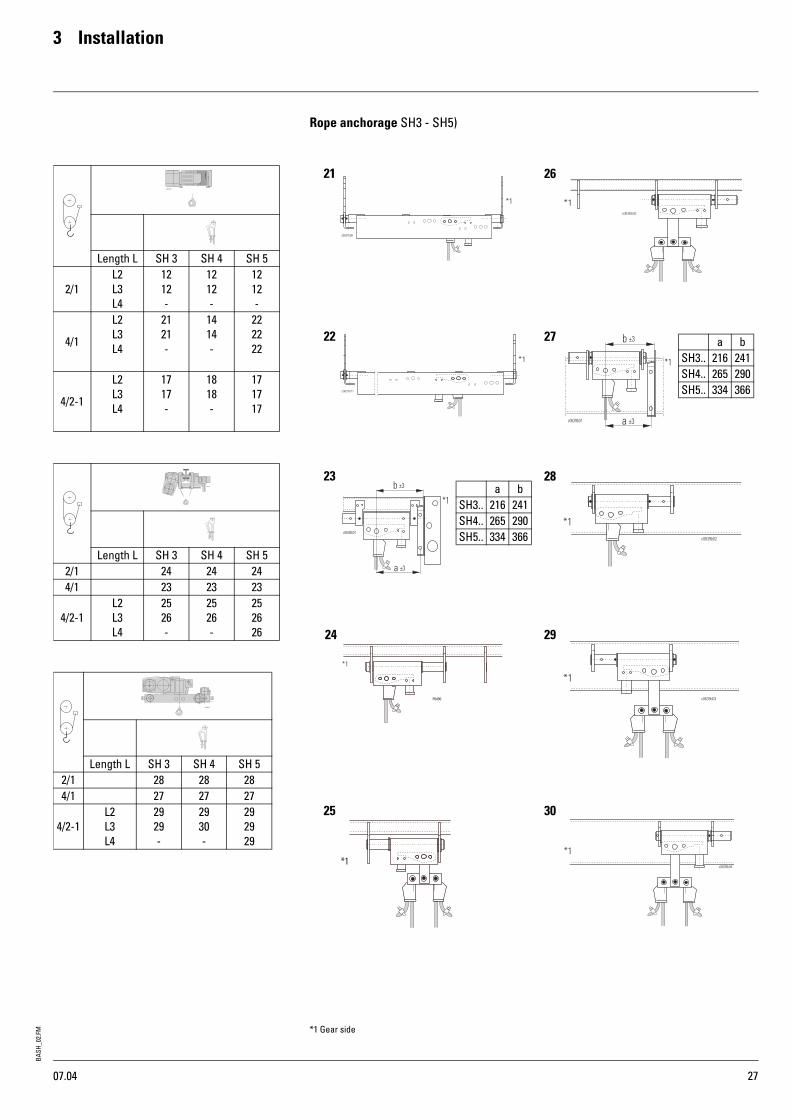
Rope anchorage SH3 - SH5)
Length L SH 3 SH 4 SH 5
2/1L2L3L4
1212-
1212-
1212-
4/1
L2L3L4
2121-
1414-
222222
4/2-1
L2L3L4
1717-
1818-
171717
Length L SH 3 SH 4 SH 52/1 24 24 244/1 23 23 23
4/2-1L2L3L4
2526-
2526-
252626
Length L SH 3 SH 4 SH 52/1 28 28 284/1 27 27 27
4/2-1L2L3L4
2929-
2930-
292929
21
22
23
24
25
26
27
28
29
30
a bSH3.. 216 241SH4.. 265 290SH5.. 334 366
a bSH3.. 216 241SH4.. 265 290SH5.. 334 366
*1 Gear side
07.04
BASH
_02.
FM
3 Installation
28
Rope anchorage (SH6)
SH 6Length L
2/1 L2-L5 324/1 L2-L5 31
2/2-1 -4/2-1 L2-L5 34
SH 6Length L
2/1 L2-L5 324/1 L2-L5 31
4/2-1 L2-L5 34
SH 6Length L
2/1 L2-L5 324/1 L2-L5 31
4/2-1 L2-L5 34
31
32
34
*1 Gear side
07.04
BASH
_02.
FM4 Commissioning
29
4.1 Commissioning The wire rope hoist has been subjected to a final inspection by the manufacturer in accordance with the EC Machinery Directive.
Commissioning must be carried out by a qualified person, see page 2. The "Safety instructions" on page 4...6 must also be observed.
The following checks must be carried out:
• Check that the wire rope hoist is completed with the original accessories as supplied (e.g. bottom hook block), see page 24.
• Check correct selection and installation of all electrical equipment, see page 21, "Connecting to mains", see page 23.
• Check that the seating of fixing screws is firm and secure, see page 8, 11, 13, 14, 58.• Check correct functioning of runway end stops.• The direction of motion of the load hook must correspond to the symbols on the
control pendant.• Check the presence and correct functioning of all safety devices.• Check emergency hoist limit switch or combined operational and emergency hoist
limit switch, see page 35.• Check overload cut-off, see page 38.• Confirm that commissioning has been duly carried out in the test log book in
section "Confirmation of commissioning".• If the wire rope hoist in conjunction with a crane system is to be subjected to a test
load during the acceptance test, the overload cut-off must be bridged (see 6.7, page 39), see circuit diagram.
• Run rope in under partial load (will improve service life).
07.04

BASH
_02.
FM
5 Operation
30
5.1 Duties of crane operator When working with wire rope hoists, the following points must be observed:
• Every day before starting work, check brakes and limit switches and inspect the system for any visible defects.
• Stop working with the crane if there are any defects which might prejudice its safety in operation.
• At close of work, secure cranes which are exposed to wind with the wind safeguard mechanism.
• The rope drum must be free of coarse foreign matter.• Do not move loads above people.• Do not leave suspended loads unattended, the control pendant must be within
easy reach.• Do not use emergency limit switch during normal operation.• Do not load above rated capacity.• Pulling loads at angles, dragging loads, or towing vehicles with the load or load
suspension equipment is forbidden!• Do not heave up any loads which are jammed.• Approach final positions for hoisting, lowering and travel in normal operation only
if an operational limit switch is fitted.• Inching operation (repeated brief activation of the motor to achieve small
movements) is not permissible. Motors and brakes could be subjected to an impermissible temperature rise. This would lead to the temperature control disconnecting and the load could then not be set down for some time. Switchgear and motors could be damaged.
• Do not move in the opposite direction until the hoist has come to a stop.• Observe the safety instructions, see page 4-6.
5.2 Operating from control pendant
5.3 Emergency stop• The emergency stop button is on the control pendant.• Press emergency stop, the system comes to a halt.• To release the emergency stop: turn the button in the direction shown.
Safety noteIf the rocker switch is no longer depressed by the operator, it returns to the 0 posi-tion, the hoist motion is automatically stopped (dead man’s control).If the hoist malfunctions, e.g. the actual motion does not correspond to the motion intended in activating the rocker switch, release the rocker switch immediately. If the motion continues, press the emergency stop button.
1st step: slow2nd step: fast
1st step: slow2nd step: fast
1st step: slowLong travel: right/left
Cross travel: right/left
Lifting/lowering:
2nd step: fast
Emergency stop
Standard design2-step
11.04
BASH
_02.
FM6 Inspection and maintenance
31
This section deals with operational reliability, availability, and maintaining the value of your wire rope hoist.Although this wire rope hoist is practically maintenance-free, the components subject to wear (e.g. wire rope, brake) and components important for ensuring explosion protection must be inspected regularly. This is required by the accident prevention regulations.Inspection and maintenance must be carried out by qualified persons who have received special training in explosion protection, see page 2.
General information on inspection and maintenance• Maintenance and repair work may only be carried out when the wire rope hoist is
unloaded.• Before starting, switch off and lock main isolator.
• Observe the requirements of the accident prevention regulations.• A general overhaul must be carried out after the useful life of the hoist has expired.• The inspection intervals given in the table apply for use in mechanism group 1 Am
or 2 m with reference to FEM 9.511 (mechanism), see page 49. If the hoist is operated in mechanism group 2 m or 3 m, the maintenance intervals must be halved in each case. Lubricants and lubrication points, see page 58.
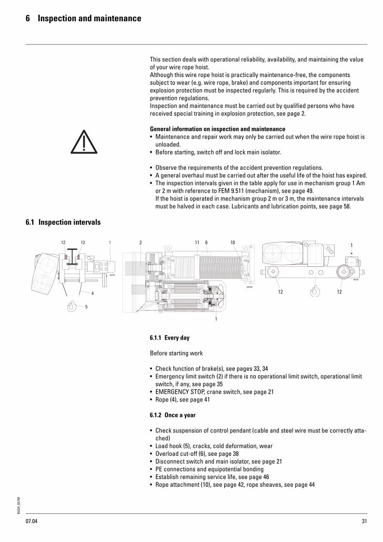
6.1 Inspection intervals
6.1.1 Every day
Before starting work
• Check function of brake(s), see pages 33, 34• Emergency limit switch (2) if there is no operational limit switch, operational limit
switch, if any, see page 35• EMERGENCY STOP, crane switch, see page 21• Rope (4), see page 41
6.1.2 Once a year
• Check suspension of control pendant (cable and steel wire must be correctly atta-ched)
• Load hook (5), cracks, cold deformation, wear• Overload cut-off (6), see page 38• Disconnect switch and main isolator, see page 21• PE connections and equipotential bonding• Establish remaining service life, see page 46• Rope attachment (10), see page 42, rope sheaves, see page 44
W0789
12
5
4
12 1
1212
W0791
11 6 102
1
W0790
07.04

BASH
_02.
FM
6 Inspection and maintenance
32
6.1.3 Once a year• Rope guide (11), see page 41, 42• Drive parts (12), flanges, wheels etc., see page 45• Screw connections, welds• End stops, buffers• Safety clearances• Power supply cable• Cable glands• Current collector• Switching functions
6.1.4 Safety notePeriodic inspections including maintenance every 12 months, possibly earlier if so prescribed by national regulations, to be performed by a fitter engaged by the manu-facturer. Similarly, heavy-duty applications (e.g. multi-shift operation..) or adverse conditions (dirt, solvents) necessitate shortening the inspection and maintenance intervals.
6.2 Maintenance intervals
6.2.1 Once a year
• Brake (20), measure air gap, replace brake disc if necessary, see page 33, 34• Overload cut-off (21), see page 38, 39• Grease rope (22) with brush, see page 59• Grease rope guide (23) with brush, see page 59• Tighten clamping points for electric cables
6.2.2 Safety noteIn adverse conditions (dirt, high temperatures, solvents), multi-shift operation, exceeding use specified by FEM, the maintenance intervals must be reduced.
W0792
22
20 23 21
20
W0793
20
W0794
07.04

BASH
_02.
FM6 Inspection and maintenance
33
6.3 Hoist motor brake Carry out work on the hoist brake only when the hoist is unloaded and the bottom hook block has been set down.
6.3.1 Checking brake• Remove fan cover (1)• Remove plug (2)• Measure air gap (S) with feeler gauge (F). N.B.: When measuring, ensure that the
feeler gauge is pushed in at least as far as depth "a" and does not catch on shoulder (!). See table for max. permissible air gap (S). The brake is not adjustable. If the max. permissible air gap (S) has been reached, the brake disc (brake rotor) must be replaced.
6.3.2 Replacing brake disc (brake rotor)
• Remove fan cover (1)• Pull off fanwheel (3), remove feather key• Disconnect brake• Unscrew fixing screws (4)• Remove magnet piece (5) together with armature disc (6) • Remove brake disc (brake rotor) (7)• Push new brake disc (brake rotor) (7) onto hub (8) and check radial play. If there is
increased play in the gearing between brake disc (7) and hub (8) the hub (8) must be pulled off the motor shaft and replaced.Before removing hub (8) please contact the manufacturer.
Replace in reverse order. Ensure that the check hole for measuring the air gap is underneath.
Check brake data according to rating plate on hoist motor!
"A"
Hoist motor type
Hoist brake
Smax.[mm]
a
[mm]12/2H33
4H33RSM16RSM16
0.80.7
25 9 Nm9 Nm
12/2H424H42
RSM32RSM32
10.8
25 9 Nm9 Nm
12/2H624H62
RSM60RSM60
1.71.8
25 22 Nm22 Nm
12/2H714H71
RSM100RSM100
1.82.0
30 22 Nm22 Nm
12/2H724H72
RSM150RSM100
1.81.2
30 22 Nm22 Nm
12/2H734H73
RSM150RSM150
1.61.4
2525
22 Nm22 Nm
4H82 RSM250 1.5 31 45 Nm24/4H92 RSM500 2.2 32 45 Nm
01.05
BASH
_02.
FM
6 Inspection and maintenance
34
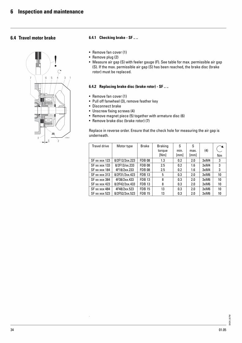
6.4 Travel motor brake 6.4.1 Checking brake - SF .. ..
• Remove fan cover (1)• Remove plug (2)• Measure air gap (S) with feeler gauge (F). See table for max. permissible air gap
(S). If the max. permissible air gap (S) has been reached, the brake disc (brake rotor) must be replaced.
6.4.2 Replacing brake disc (brake rotor) - SF .. ..
• Remove fan cover (1)• Pull off fanwheel (3), remove feather key• Disconnect brake• Unscrew fixing screws (4)• Remove magnet piece (5) together with armature disc (6) • Remove brake disc (brake rotor) (7)
Replace in reverse order. Ensure that the check hole for measuring the air gap is underneath.
Travel drive Motor type Brake Braking torque[Nm]
Smin.[mm]
Smax.[mm]
(4)Nm
SF xx xxx 123 8/2F12/2xx.223 FDB 08 1.3 0.2 2.0 3xM4 3SF xx xxx 133SF xx xxx 184
8/2F13/xx.2334F18/2xx.233
FDB 08FDB 08
2.52.5
0.20.2
1.61.6
3xM43xM4
33
SF xx xxx 313 8/2F31/2xx.423 FDB 13 5 0.3 2.0 3xM6 10SF xx xxx 384SF xx xxx 423
4F38/2xx.4338/2F42/2xx.433
FDB 13FDB 13
88
0.30.3
2.02.0
3xM63xM6
1010
SF xx xxx 484SF xx xxx 523
4F48/2xx.5238/2F52/2xx.523
FDB 15FDB 15
1313
0.30.3
2.02.0
3xM63xM6
1010
.
01.05

BASH
_02.
FM6 Inspection and maintenance
35
6.5 Hoist limit switch 6.5.1 Description of systemThe wire rope hoist is equipped as standard with an emergency limit switch for disconnecting in top and bottom hook position. (Switching points A↑ and A↓). The gear limit switch (GE-S) is installed in the panel box on the gear.If original R. STAHL controls/circuit diagrams are used, the corresponding hoisting direction and cross and long travel are disabled when the limit switch is activated. The opposing hoisting direction is clear.
An additional operational limit switch *2 for disconnecting in top and bottom hook position during normal operation can be fitted as an option. (Additional switching points B↑ and B↓).The control pendant includes a lockable, self-resetting key switch (override button U) for checking the emergency limit switch.If the operational limit switch fails, the hoist can only leave the end position by activating this key switch (U). The key must be kept separate.
6.5.2 Safety notesThe limit switch is constructed according to the state of the art and is safe in operation. However dangers may arise if it is used incorrectly and not for its intended purpose.
6.5.3 Testing emergency hoist limit switch
• Test at fast and creep speed without load.1 Activate the "up" button on the control pendant carefully, observing the hoisting
motion, until the limit switch disconnects in top hook position (A↑).2 Minimum clearance "a" between bottom hook block and nearest obstacle, see
table, if necessary reset the limit switch, see page 36.3 Press the "down" button and check bottom hook position in the same way.4 Minimum clearance between rope guide (S) and clamping claws (K) for rope
anchorage = 20 mm, see sketch, if necessary reset limit switch, see page 36.
6.5.4 Testing combined operational and emergency hoist limit switch• Test at fast and creep speed without load.1 Activate the "up" button on the control pendant carefully, observing the hoisting
motion, until the limit switch disconnects in the highest operational hook position (B↑).
2 Press override button (U) on control pendant and at the sametime the "up" button until the emergency limit switch disconnects (A↑). If the hoist does not continue to move, the emergency limit switch was activated in step 1 and the operational limit switch is not working.
3 Minimum clearance "a" see table.4 Press "down" button and check bottom hook position in the same way.5 Minimum clearance between rope guide (S) and clamping claws (K) for rope
anchorage = 20 mm, see sketch, if this is not the case, reset limit switch.• The clearances between the switching points for operational and emergency limit
switches are set for normal operating conditions, however they can be adjusted if necessary.
a [mm]50 Hz 60 Hz
130 150
70 80
40 50
U
*1 Effective hook path with operational limit switch*2 Option
07.04
BASH
_02.
FM
6 Inspection and maintenance
36
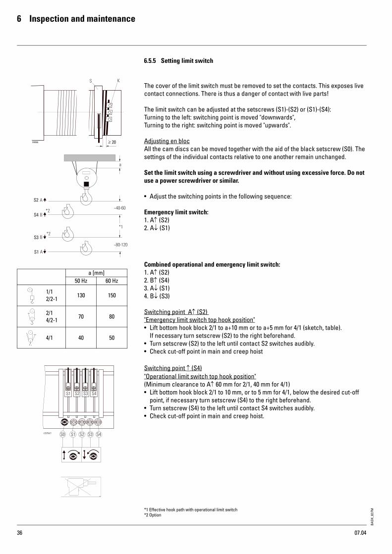
6.5.5 Setting limit switch
The cover of the limit switch must be removed to set the contacts. This exposes live contact connections. There is thus a danger of contact with live parts!
The limit switch can be adjusted at the setscrews (S1)-(S2) or (S1)-(S4):Turning to the left: switching point is moved "downwards",Turning to the right: switching point is moved "upwards".
Adjusting en blocAll the cam discs can be moved together with the aid of the black setscrew (S0). The settings of the individual contacts relative to one another remain unchanged.
Set the limit switch using a screwdriver and without using excessive force. Do not use a power screwdriver or similar.
• Adjust the switching points in the following sequence:
Emergency limit switch:1. A↑ (S2)2. A↓ (S1)
Combined operational and emergency limit switch:1. A↑ (S2)2. B↑ (S4)3. A↓ (S1)4. B↓ (S3)
Switching point A↑ (S2) "Emergency limit switch top hook position"• Lift bottom hook block 2/1 to a+10 mm or to a+5 mm for 4/1 (sketch, table).
If necessary turn setscrew (S2) to the right beforehand.• Turn setscrew (S2) to the left until contact S2 switches audibly.• Check cut-off point in main and creep hoist
Switching point ↑ (S4)"Operational limit switch top hook position"(Minimum clearance to A↑ 60 mm for 2/1, 40 mm for 4/1)• Lift bottom hook block 2/1 to 10 mm, or to 5 mm for 4/1, below the desired cut-off
point, if necessary turn setscrew (S4) to the right beforehand.• Turn setscrew (S4) to the left until contact S4 switches audibly.• Check cut-off point in main and creep hoist.
a [mm]50 Hz 60 Hz
1/12/2-1 130 150
2/14/2-1 70 80
4/1 40 50
*1 Effective hook path with operational limit switch*2 Option
07.04

BASH
_02.
FM6 Inspection and maintenance
37
6.5.5 Setting limit switch (continued)
Switching point A↓ (S1)"Emergency limit switch bottom hook position"(Minimum clearance between rope guide (S) and clamping claws (K) for rope anchorage = 20 mm, see sketch)
Set bottom hook position so that the bottom hook block does not touch the ground (would cause slack rope).
• Lower bottom hook block 2/1 to 120 mm, or 60 mm for 4/1, above desired hook position, if necessary turn setscrew (S1) to the left beforehand.
• Turn setscrew (S1) to the right until contact S1 switches audibly.• Check cut-off point in main and creep hoist.
Switching point B↓ (S3) "Operational limit switch bottom hook position"(Minimum clearance to A↑ 120 mm for 2/1, 80 mm for 4/1)
• Lower bottom hook block 2/1 to 120 mm, or 60 mm for 4/1, above desired hook posi-tion, if necessary turn setscrew (S3) to the left beforehand
• Turn setscrew (S3) to the right until contact S3 switches audibly• Check cut-off point in main and creep hoist.
.
6.5.6 Servicing gear limit switch
Maintenance work is restricted to checking the cut-off points. No maintenance or inspection is necessary for the gear limit switch itself.
Any dust deposits that may be visible when the housing is opened must on no account be removed with compressed air as this would force the dust into the contacts and impair the switching function.
On no account must benzene or other solvents be used to clean the limit switch!
a [mm]50 Hz 60 Hz
1/12/2-1 130 150
2/14/2-1 70 80
4/1 40 50
Safety note:Incorrectly set limit switches may cause serious accidents!
*1 Effective hook path with operational limit switch*2 Option
07.04
BASH
_02.
FM
6 Inspection and maintenance
38
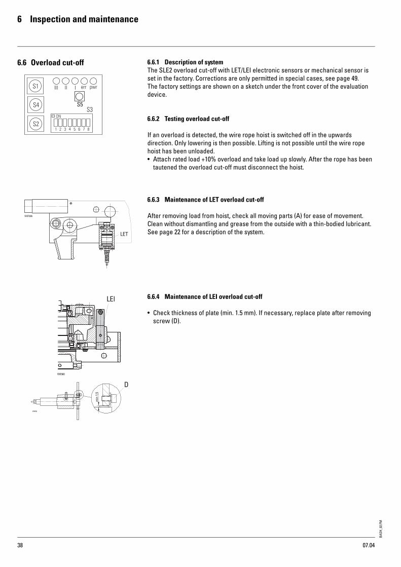
6.6 Overload cut-off 6.6.1 Description of systemThe SLE2 overload cut-off with LET/LEI electronic sensors or mechanical sensor is set in the factory. Corrections are only permitted in special cases, see page 49.The factory settings are shown on a sketch under the front cover of the evaluation device.
6.6.2 Testing overload cut-off
If an overload is detected, the wire rope hoist is switched off in the upwards direction. Only lowering is then possible. Lifting is not possible until the wire rope hoist has been unloaded.• Attach rated load +10% overload and take load up slowly. After the rope has been
tautened the overload cut-off must disconnect the hoist.
6.6.3 Maintenance of LET overload cut-off
After removing load from hoist, check all moving parts (A) for ease of movement. Clean without dismantling and grease from the outside with a thin-bodied lubricant.See page 22 for a description of the system.
6.6.4 Maintenance of LEI overload cut-off
• Check thickness of plate (min. 1.5 mm). If necessary, replace plate after removing screw (D).
S5
W0788b
LET
07.04

BASH
_02.
FM6 Inspection and maintenance
39
6.6.5 Maintenance of overload cut-off with mechanical sensor
• Clean, check and grease spring bolt guide (c). The spring (d) is pretensioned with the setscrew (b). This setting must not be altered.
• The position of the the switching pin (a) must not be altered either.
If dismantling is necessary due to excessive deposits of dirt, dimension (k) must be determined beforehand. When reassembling, setscrew (b) must be reset to dimen-sion (k).
6.7 Crane test 1. Carefully remove front cover of evaluation device.2. The cut-off point is increased by pressing button (S5) permitting the test load of
125% to be lifted.
The device automatically returns to the original cut-off point after 30 minutes.
W0797
c
d
b
a
k
W0798
S5
I I II I I pw rer r
Button (S5) pressed.Cut-off threshhold is raised.
Safety note:Extremely heavy loads can be lifted.Risk of accident!
07.04
BASH
_02.
FM
6 Inspection and maintenance
40
6.8 Rope drive 6.8.1 Rope and rope attachment - general informationAfter commissioning a new wire rope hoist, or after replacing the rope, the rope of multi-fall hoists may twist. This can be seen from the bottom hook block turning, particularly when unloaded. Twisting in the rope prejudices safety and service life.
Remove any twists!
• Regularly inspect the rope for twisting. To do so, run the hoist into highest and lowest hook positions without load.
• If any twisting is detected, untwist the rope immediately. See page 24, "Reeving rope" and see page 42, "Removing rope".
• Check rope. Take particular note of the sections of rope near rope pulleys, return pulleys or equalizing pulleys and in the region of the rope anchorage.
• If any of the following damage occurs, replace the rope immediately.
1 Excess visible wire fractures, see page 41, table.The rope must be free of load for testing to facilite detecting any broken wires when bending the rope by hand (approximately by radius of rope sheave).
2 Nest of wire fractures or broken strand.3 Diameter reduced by 10% due to corrosion or wear (independent of breakage).4 Diameter reduced due to structural changes over considerable sections.5 Formation of baskets or loops, knots, necking, kinks or other mechanical damage.6 Corkscrew-type deformation. Divergence due to deformation: ≥ 1/3x rope diameter.7 In addition, the rope must be replaced as required by DIN 15020, FEM 9.661 and ISO
4309.8 In certain applications (e.g. twist-free wire rope, constant deadweight, recurrent
stopping position, automatic operation etc.) wire fractures may occur inside the rope without being visible from outside.Risk of accident!In case of doubt please contact the manufacturer.
07.04

BASH
_02.
FM6 Inspection and maintenance
41
6.8.2 Replacement of wire rope due to broken wires
Twist-free wire rope
Non-twist-free wire rope
* See data sheet for rope make-up
6.8.3 Removing rope guide
1st method (preferable!)• Unscrew protective plate (1) under the rope drum at points (a). The rope guide can
then be rotated freely. Do not unscrew stop with bearing (2)!• Unscrew screws (3).• Unscrew rope guide safety cable (4) (if any) on one side.• Remove half-rings.• Unhook rope tensioning spring.
2nd method• Unscrew stop with bearing (2) from rope guide. The rope guide can then be rotated
freely. Continue as described under 1.
Caution: The stop with bearing (2) is locked with a conical spring washer DIN 6796. This must be refitted correctly.
Rope diameter [mm] 5.5 7 9 12 14 20Number of external strands 12 12 15 15 15 18Rope make-up * 18X7+SE d1315z d1315z d1315z d1315z d1318Broken wires visible 1Bm, 1Am 2m - 4m
48
48
510
510
510
611
over a length of [mm] 33 42 54 72 84 120orBroken wires visible 1Bm, 1Am 2m - 4m
816
816
1016
1019
1019
1122
over a length of [mm] 165 210 270 360 420 600
Rope diameter [mm] 5.5 7 9 9 12 12,5 14 20Number of external strands 6 8 8 8 8 8 8 8Rope make-up * 6x19W 8x19W 8x19W Alphalift Turbolift 8x19W 8x19W 8x36WSBroken wires visible 1Bm, 1Am 2m - 4m
510
613
613
613
918
618
613
1224
over a length of [mm] 33 42 54 54 72 75 84 120orBroken wires visible 1Bm, 1Am 2m - 4m
1019
1326
1326
1326
1835
1326
1326
2448
over a length of [mm] 165 210 270 270 360 375 420 600
SH3 - SH5
SH6
SH6 - 2/1
07.04

BASH
_02.
FM
6 Inspection and maintenance
42
6.8.4 Replacing wire ropeSH wire rope hoists have a special rope which is the optimum for the most common applications. The substitute rope must be equivalent to the original in terms of quality, strength and make-up. Please consult the works certificate or the rope certificate to see which rope is fitted.
In the case of 2 wire ropes with different lays
• wire rope with right-hand lay (DS1) on rope drum with left-hand groove
• wire rope with left-hand lay (DS2) on rope drum with rigth-hand groove
• The direction of lay of the wire ropes makes a V-pattern (see sketch).
Removing rope• Lower bottom hook block to just above the lowest hook position and set it down on
a firm support.• Release end of wire rope in rope anchorage (rope clamp with rope wedge).• Run the remaining rope off the drum.• Unscrew the fixing screws in the clamping plates on the rope drum.
Fitting rope• Unroll new rope out straight if possible, without twists, kinks or loops. Protect rope
from dirt.• Attach rope to rope drum with all the clamping plates (do not forget the lock
washers!) Allow the rope end to project by approx. 30-40 mm.• Tightly wind about 5-10 turns onto the drum under power. Let the rope run through
a greased rag. For type of grease see page 59.• Fit rope guide, see page 43 "Fitting rope guide".• Reeve the loose end of the rope according to the number of falls, fasten with the
rope wedge and secure with a rope clamp, see page 26, "Rope anchorage".• Retighten clamping plates. For tightening torques see table.• Run rope in with partial load.
• Caution! Risk of accident!• After fitting a new rope, or shortening the old one, reset the hoist limit switch. See
page 36, "Setting hoist limit switch".• If the new rope twists after some time in operation, untwist the rope immediately.
See page 25, "Reeving rope" and "Removing rope".
Type M..Nm
SH 3M6 10M10 40
SH 4 M10 50
SH 5M10 50M12 87
SH 6 M12M16
87210
07.04

BASH
_02.
FM6 Inspection and maintenance
43
6.8.5 Fitting rope guide
• Grease thread and rope guide groove thoroughly.• Place the half-ring (1) with the short window section onto the rope drum next to the
last rope winding so that the rope exits from the region of the window (x).• Push rope tensioning spring (2) into the guide groove of the half-ring (1) and hook
the ends of the spring together. A special tool (a), see sketch, will make this easier.• Place the second half-ring (3) with the long rope exit window on the rope drum so
that the rope exits from the drum groove through the window straight and without kinking. The second half-ring must lie flush against the first.
• Bolt the two half-rings together with pressure screws and bolts (5)• The rope guide must rest lightly on the drum and be able to be turned by hand.
If this is not the case the guide has been fitted incorrectly or the rope drum is damaged.
• Bolt stop with bearing and conical spring washer (6) to the rope guide.• Fit rope guide safety catch (7) (SH6 - 2/1 L4-L5)• Bolt on protective plate (8).
07.04

BASH
_02.
FM
6 Inspection and maintenance
44
6.8.6 Inspection and maintenance of rope sheave • Check rope sheaves for wear. We recommend having them checked by personnel
trained by us. They should also be checked for easy running, indicating that the ball bearings are in good condition.
Wear on rope sheave
Notes on limits for wear
The rope sheave must be replaced if the wall thickness as measured is <t min or the groove depth as measured is >h max. Furthermore, the rope sheave must be replaced when replacing the wire rope if the rope strands have dug into the base of the groove. Impressions of single wires are acceptable.A rope sheave must also be replaced if the radius of the base of the groove R has become too small for the new rope due to reduction in diameter of the old rope or wear.N.B.The negative profile of the rope in the base of the groove may provide optimum contact to the wire rope currently fitted.
Rope sheaves should be rotated without load on the rope to check the easy and concentric running of the bearings.
Bottom hook blocksThe bottom hook block must be checked for damage. Deformations, cracks and cuts caused by impact must be assessed.The damage can only be assessed by trained maintenance personnel.
Rope sheavesPart number ØD t min h max h new01 430 01 53 0 98 4 12.5 1101 430 04 53 0 100 4 12.5 1001 430 00 53 0 125 4 13.5 1222 330 00 53 0 140 4 13.5 1201 430 06 53 0 152 4 22 20.503 330 20 53 0 160 4 18 16.524 330 00 53 0 200 5.7 23 2101 430 05 53 0 218 5.7 26 24.501 430 03 53 0 225 5.7 23 2103 330 40 53 0 250 5.7 27.5 2525 330 00 53 0 375 7 37 3425 330 03 53 0 375 7 35.5 32.546 330 00 53 0 400 8 33 3026 330 01 53 0 450 11 39 3509 430 00 53 0 450 11 39 3543 330 01 53 0 480 10 36.5 32.5
on one sideand at base
on both sidesand at base
on both sidesand at base
Measuring depth of base of groove with depth gauge
Measuring thickness of wallwith special caliper gauge
07.04
BASH
_02.
FM6 Inspection and maintenance
45
= Limits for wear
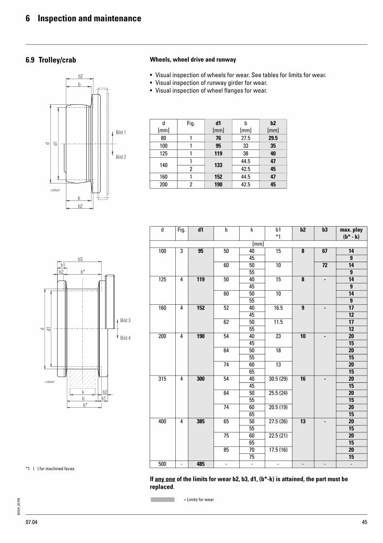
6.9 Trolley/crab Wheels, wheel drive and runway
• Visual inspection of wheels for wear. See tables for limits for wear.• Visual inspection of runway girder for wear.• Visual inspection of wheel flanges for wear.
If any one of the limits for wear b2, b3, d1, (b*-k) is attained, the part must be replaced.
d[mm]
Fig. d1[mm]
b[mm]
b2[mm]
80 1 76 27.5 29.5100 1 95 33 35125 1 119 38 40
1401
13344.5 47
2 42.5 45160 1 152 44.5 47200 2 190 42.5 45
d Fig. d1 b k b1*1
b2 b3 max. play(b* - k)
[mm]100 3 95 50 40 15 8 67 14
45 960 50 10 72 14
55 9125 4 119 50 40 15 8 - 14
45 960 50 10 14
55 9160 4 152 52 40 16.5 9 - 17
45 1262 50 11.5 17
55 12200 4 190 54 40 23 10 - 20
45 1564 50 18 20
55 1574 60 13 20
65 15315 4 300 54 40 30.5 (29) 16 - 20
45 1564 50 25.5 (24) 20
55 1574 60 20.5 (19) 20
65 15400 4 385 65 50 27.5 (26) 13 - 20
55 1575 60 22.5 (21) 20
65 1585 70 17.5 (16) 20
75 15500 - 485 - - - - - -
07.04
*1 ( ) for machined faces
BASH
_02.
FM
6 Inspection and maintenance
46
*1 Safe Working Period
6.10Remaining service life According to FEM 9.755, the operating mode and operating time must be established by the user, see page 2, and recorded in the test log book in order to calculate the remaining service life. After the service life has expired a general overhaul (S.W.P.) *1 must be carried out.Wire rope hoists are equipped ex factory with a suitable registration device. Various devices are used:
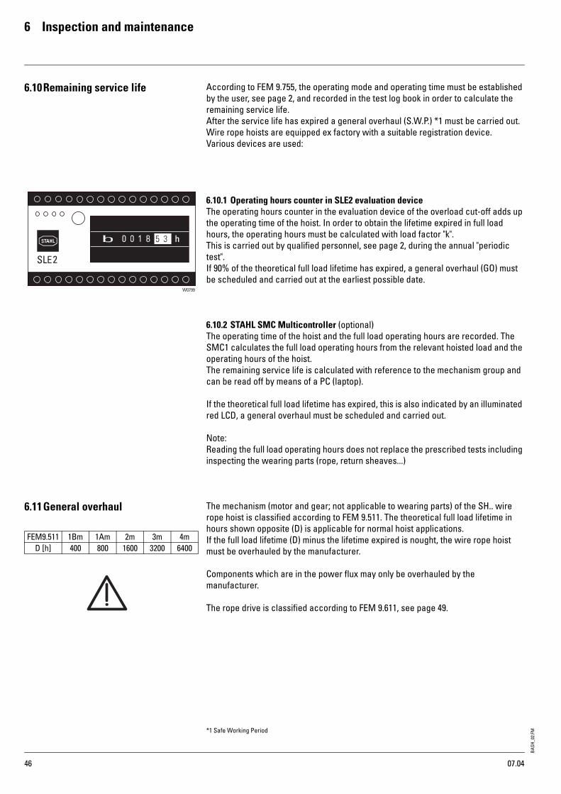
6.10.1 Operating hours counter in SLE2 evaluation device The operating hours counter in the evaluation device of the overload cut-off adds up the operating time of the hoist. In order to obtain the lifetime expired in full load hours, the operating hours must be calculated with load factor "k".This is carried out by qualified personnel, see page 2, during the annual "periodic test".If 90% of the theoretical full load lifetime has expired, a general overhaul (GO) must be scheduled and carried out at the earliest possible date.
6.10.2 STAHL SMC Multicontroller (optional)The operating time of the hoist and the full load operating hours are recorded. The SMC1 calculates the full load operating hours from the relevant hoisted load and the operating hours of the hoist.The remaining service life is calculated with reference to the mechanism group and can be read off by means of a PC (laptop).
If the theoretical full load lifetime has expired, this is also indicated by an illuminated red LCD, a general overhaul must be scheduled and carried out.
Note:Reading the full load operating hours does not replace the prescribed tests including inspecting the wearing parts (rope, return sheaves...)
6.11General overhaul The mechanism (motor and gear; not applicable to wearing parts) of the SH.. wire rope hoist is classified according to FEM 9.511. The theoretical full load lifetime in hours shown opposite (D) is applicable for normal hoist applications.If the full load lifetime (D) minus the lifetime expired is nought, the wire rope hoist must be overhauled by the manufacturer.
Components which are in the power flux may only be overhauled by the manufacturer.
The rope drive is classified according to FEM 9.611, see page 49.
2
W0799
FEM9.511 1Bm 1Am 2m 3m 4mD [h] 400 800 1600 3200 6400
07.04

BASH
_02.
FM7 Fault-finding
47
7.1 What is to be done if? 7.1.1 Wire rope hoist does not start, motor hums• Not all power phases are present.1 Check fuses,2 Check supply cable,3 Check control pendant and switchgear.
7.1.2 Wire rope hoist does not start after a long stoppage, or starts with difficulty, motor hums
• Hoist brake is stuck.1 Remove fan cover2 Dismantle brake
7.1.3 Loud clicking when switching on• Measure air gap, see page 33, 34.• Replace brake disc if necessary, see page 33, 34.
7.1.4 Braking path too long• Brake displacement too long.• Brake lining worn.• Replace brake disc, see page 33, "Hoist brake", see page 34, "Trolley brake",
7.1.5 Bottom hook block and rope rotate• Rope is twisted.• Untwist rope, see page 42, "Replacing rope".
7.1.6 Cross travel not possible• Hoist is in highest hook position, cross and long travel are disconnected.• Lower bottom hook block until up motion is possible again
7.1.7 Lowering not possible• Operational hoist limit switch is defective.• Emergency limit switch has reacted.1. Release override button on control pendant using the key supplied.2. Press override button and down button simultaneously.
Continued on page 48
07.04

BASH
_02.
FM
7 Fault-finding
48
7.1 What is to be done if? (continued) 7.1.8 Load is not lifted
• SLE2 overload cut-off has been actuated or is defective.1 Check setting, see page 38, 39.2 Actions for SLE2
LED I...III "on" and LED err => error.
Actions to eliminate an error may only be performed by trained personnel.
Error specification - Sensor current <1mA
Elimination of error - Check voltage supply- Check sensor current (terminal 21)- Check connecting cable- Replace sensor
Error specification - Overload
Elimination of error - Remove load from hoist
Error specification - Overtemperature
Elimination of error - Allow motor to cool down - check PTC thermistors
Error specification - Control error
Elimination of error - Check wiring(lifting terminal 3 and lowering terminal 4 are activated simultaneously)
Error specification - System error
Elimination of error - Check voltage (terminal 6 and terminal 11)- Switch load monitor off/on- Replace load monitor
Error specification - Sensor current >24.5mA
Elimination of error - Check sensor current (terminal 21)- Replace load monitor- Replace sensor
16 17
ϑ1
SLE2
UB
18 19 20 21
II II I I pw rerr
UBS GD I+
W0800
I I II I I pw rer r
I I II I I pw rer r
I I II I I pw rer r
I I II I I pw rer r
I I II I I pw rer r
07.04

BASH
_02.
FM7 Fault-finding
49
7.1.9 Correction of cut-off threshhold with LET/LEI electronic sensors
• The specific hoist installation conditions may make it necessary to correct the cut-off threshhold.
• Corrections to the cut-off threshhold may be carried out by trained personnel only.The evaluation device will only accept alterations of -20% to +8% on the factory setting. If these limits are exceeded, I and II flash.
- Rough adjustment with S4, ~16%/ switching position, - Fine adjustment with S2,~1%/switching position, see page 38, 39.
Caution: Do not exceed 110% nominal load
7.1.10 Correction of cut-off threshhold with LMS mechanical sensor
Unscrew locknut (a), adjust switching pin (b) and lock again.Turn the switching pin by a maximum of one turn to the right or two turns to the left.
W0795
S5
I I II I I pw rer r
Permissible cut-off range exceeded or below target-lower cut-off threshhold (S2/S4)-raise cut-off threshhold (S2/S4)
W0797b
ba
07.04

BASH
_02.
FM
8 Technical data
50
8.1 FEM classification Classification of mechanism, rope drive and motor in acc. with FEM for SH
8.2 Conditions of use The hoist is designed for use in industry and for the ambient conditions usual in industry in non-hazardous areas.Special measures must be taken for particular applications such as e.g. high degree of chemical pollution, outdoor use, offshore application, etc. R. STAHL will be pleased to advise you.
Protection against dust and moisture to EN 60 529IP 55
Permissible ambient temperatures-20°C ... +40°C (standard)-20°C ... +60°C (option-5°C ... +80°C (option)-40°C ... +40°C (off-standard design)
Type FEM 9.661 FEM 9.511 FEM 9.683 Typ FEM 9.661 FEM 9.511 FEM 9.683
Rope
driv
e
Mec
hani
sm
Mot
or
Rope
driv
e
Mec
hani
sm
Mot
or
1/12/2-1
2/14/2-1
4/1 6/1 8/1
500 1000 2000 SH 3005-25SH 3005-40
3m 4m 4m
630 1250 2500 SH 3006-25SH 3006-40
2m 3m 4m
800 1600 3200 SH 3008-20SH 3006-32
2m 2m 4m SH 4008-25SH 4008-40
3m 4m 4m
1000 2000 4000 SH 4010-25SH 4010-40
2m 3m 4m
1250 2500 5000 SH 4012-20SH 4012-32
2m 2m 4m
1600 3200 6300 SH 4016-16SH 4016-25
1Am 1Am 4m SH 5016-25SH 5016-40
3m 4m 4m
2000 4000 8000 SH 5020-25SH 5020-40
2m 3m 4m
2500 5000 10000 SH 5025-20SH 5025-32
2m 2m 4m SHR 6025-20SHR 6025-32SHR 6025-40
2m 4m 4m
3200 6300 12500 SH 5032-16SH 5032-25
1Am 1Am 4m SHR 6032-16SHR 6032-25SHR 6032-40
2m 4m 4m
4000 8000 16000 SHR 6040-12SHR 6040-20SHR 6040-32
1Am 3m 4m SH 6040-12SH 6040-20SH 6040-32
3m 3m 4m
5000 10000 20000 SH 6050-16SH 6050-25
2m 2m 4m SH 6050-40 2m 2m 1Am
6300 12500 25000 SH 6063-12SH 6063-20
1Am 1Am 4m SH 6063-32 1Am 1Am 1Am
8000 16000 32000 50000 63000
10000 20000 40000 63000 80000
12500 25000 50000 80000 100000
07.04
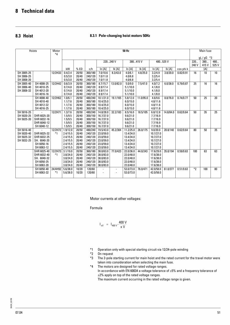
BASH
_02.
FM8 Technical data
51
8.3 Hoist 8.3.1 Pole-changing hoist motors 50Hz
Motor currents at other voltages:
Formula
*1 Operation only with special starting circuit via 12/24-pole winding*2 On request*3 The 2-pole starting current for main hoist and the rated current for the travel motor were
taken into consideration when selecting the main fuse.*4 The motors are designed for rated voltage ranges.
In accordance with EN 60034 a voltage tolerance of ±5% and a frequency tolerance of ±2% apply on top of the rated voltage ranges.The maximum current occurring in the rated voltage range is given.
Hoists Motor *4
50 Hz Main fuse
gL / gG *3220...240 V 380...415 V 480...525 V
220... 240 V
380... 415 V
480... 525 V
kW % ED c/h In [A] Ik [A] In [A] Ik [A] In [A] Ik [A] cos phi k [A]SH 3005-25 SH 3006-25 SH 3008-20
12/2H33 0.4/2.4 0.5/3.0 0.5/3.0
20/50 20/40 20/40
360/180 240/120 240/120
7.0/10.6 7.0/11.8 7.0/11.8
8.3/43.0 4.0/6.1 4.0/6.8 4.0/6.8
4.8/25.0 3.2/4.9 3.2/5.4 3.2/5.4
3.8/20.0 0.82/0.91 16 10 10
SH 3005-40 SH 3006-40 SH 3008-32
SH 4008-25 SH 4010-25 SH 4012-20 SH 4016-16
12/2H42 0.6/3.9 0.7/4.8 0.7/4.8 0.7/4.8
20/50 20/40 20/40 20/40
360/180 240/120 240/120 240/120
8.7/15.7 8.9/17.4 8.9/17.4 8.9/17.4
13.0/82.0 5.0/9.0 5.1/10.0 5.1/10.0 5.1/10.0
7.5/47.0 4.0/7.2 4.1/8.0 4.1/8.0 4.1/8.0
6.0/38.0 0.79/0.87 25 16 16
SH 4008-40 SH 4010-40 SH 4012-32 SH 4016-25
12/2H62 1.0/6.1 1.1/7.6 1.1/7.6 1.1/7.6
20/50 20/40 20/40 20/40
480/240 360/180 360/180 360/180
10.1/21.0 10.4/25.0 10.4/25.010.4/25.0
19.1/165 5.8/12.0 6.0/15.0 6.0/15.06.0/15.0
11.0/95.0 4.6/9.6 4.8/11.6 4.8/11.6 4.8/11.6
8.8/76.0 0.74/0.77 50 25 20
SH 5016-25 SH 5020-25 SH 5025-20
- SHR 6025-20 SHR 6032-16 SHR 6040-12SH 6040-12
12/2H71 1.3/7.6 1.5/9.5 1.5/9.5 1.5/9.51.5/9.5
20/50 20/40 20/40 20/4020/40
480/240 300/150 300/150 300/150300/150
14.8/28.0 16.7/37.0 16.7/37.0 16.7/37.016.7/37.0
32.2/183 8.5/16.0 9.6/21.0 9.6/21.0 9.6/21.09.6/21.0
18.5/105 6.8/12.8 7.7/16.9 7.7/16.97.7/16.97.7/16.9
14.8/84.0 0.62/0.64 50 35 25
SH 5016-40 SH 5020-40 SH 5025-32 SH 5032-25
- SHR 6025-32 SHR 6032-25 SH. 6040-20 SH 6050-16 SH 6063-12
12/2H72 *1
1.9/12.0 2.4/15.5 2.4/15.5 2.4/15.5 2.4/15.5 2.4/15.5
20/50 20/40 20/40 20/40 20/40 20/40
480/240 240/120 240/120 240/120 240/120 240/120
19.5/43.0 23.0/59.0 23.0/59.023.0/59.023.0/59.023.0/59.0
45.2/304 11.2/25.0 13.4/34.0 13.4/34.0 13.4/34.0 13.4/34.0 13.4/34.0
26.0/175 9.0/20.0 10.7/27.0 10.7/27.0 10.7/27.0 10.7/27.0 10.7/27.0
20.8/140 0.62/0.64 80 50 35
SHR 6025-40 SHR 6032-40 SH. 6040-32 SH 6050-25 SH 6063-20
12/2H73 *1
3.1/19.0 3.8/24.0 3.8/24.0 3.8/24.0 3.8/24.0
20/50 20/40 20/40 20/40 20/40
360/180 240/120 240/120 240/120 240/120
38.0/63.0 38.0/83.0 38.0/83.038.0/83.038.0/83.0
77.0/423 22.0/36.0 22.0/48.0 22.0/48.022.0/48.022.0/48.0
44.0/243 17.6/29.0 17.6/38.0 17.6/38.017.6/38.017.6/38.0
35.0/194 0.59/0.63 100 63 63
SH 6050-40 SH 6063-32
24/4H92 *1
5.6/38.0 5.6/38.0
10/2010/20
120/60 120/60
- -
- -
53.0/73.053.0/73.0
76.0/471 42.0/58.042.0/58.0
61.0/377 0.51/0.63 *2 100 80
07.04

BASH
_02.
FM
8 Technical data
52
8.3.2 Pole-changing hoist motors 60Hz
Motor currents at other voltages:
Formula
*1 Operation only with special starting circuit via 12/24-pole winding*2 On request*3 The 2-pole starting current for main hoist and the rated current for the travel motor were
taken into consideration when selecting the main fuse.*4 The motors are designed for rated voltage ranges.
In accordance with EN 60034 a voltage tolerance of ±5% and a frequency tolerance of ±2% apply on top of the rated voltage ranges.The maximum current occurring in the rated voltage range is given.
Hoists Motor *4
60 Hz Main fuse
gL / gG *3380...415 V 440...480 V 550...600 V
380... 415 V
440... 480 V
550... 600 V
kW % ED c/h In [A] Ik [A] In [A] Ik [A] In [A] Ik [A] cos phi k [A]SH 3005-25 SH 3006-25 SH 3008-20
12/2H33 0.4/2.9 0.6/3.6 0.6/3.6
20/50 20/40 20/40
360/180 240/120 240/120
4.6/7.04.6/7.84.6/7.8
5.5/29.0 4.0/6.14.0/6.84.0/6.8
4.8/25.0 3.2/4.93.2/5.43.2/5.4
3.8/20.0 0.82/0.91 16 10 10
SH 3005-40 SH 3006-40 SH 3008-32
SH 4008-25 SH 4010-25 SH 4012-20 SH 4016-16
12/2H42 0.7/4.7 0.9/5.8 0.9/5.8 0.9/5.8
20/50 20/40 20/40 20/40
360/180 240/120 240/120 240/120
5.8/10.45.9/11.55.9/11.55.9/11.5
8.6/54.0 5.0/9.05.1/10.05.1/10.05.1/10.0
7.5/47.0 4.0/7.24.1/8.04.1/8.04.1/8.0
6.0/38.0 0.79/0.87 20 16 16
SH 4008-40 SH 4010-40 SH 4012-32 SH 4016-25
12/2H62 1.2/7.3 1.3/9.1 1.3/9.1 1.3/9.1
20/50 20/40 20/40 20/40
480/240 360/180 360/180 360/180
6.7/13.86.9/17.06.9/17.06.9/17.0
12.7/109 5.8/12.06.0/15.06.0/15.06.0/15.0
11.0/95.0 4.6/9.64.8/11.64.8/11.64.8/11.6
8.8/76.0 0.74/0.77 35 25 20
SH 5016-25 SH 5020-25 SH 5025-20
- SHR 6025-20 SHR 6032-16 SHR 6040-12SH 6040-12
12/2H71 1.5/9.1 1.8/11.4 1.8/11.4 1.8/11.41.8/11.4
20/50 20/40 20/40 20/4020/40
480/240 300/150 300/150 300/150300/150
9.8/18.411.0/24.011.0/24.011.0/24.011.0/24.0
21.3/121 8.5/16.09.6/21.09.6/21.09.6/21.09.6/21.0
18.5/105 6.8/12.87.7/16.97.7/16.97.7/16.97.7/16.9
14.8/84.0 0.62/0.64 35 35 25
SH 5016-40 SH 5020-40 SH 5025-32 SH 5032-25
- SHR 6025-32 SHR 6032-25 SH. 6040-20 SH 6050-16 SH 6063-12
12/2H72 *1
2.3/14.4 2.9/18.6 2.9/18.6 2.9/18.6 2.9/18.6 2.9/18.6
20/50 20/40 20/40 20/40 20/40 20/40
480/240 240/120 240/120 240/120 240/120 240/120
12.9/29.015.4/39.015.4/39.015.4/39.015.4/39.015.4/39.0
29.9/201 11.2/25.013.4/34.013.4/34.013.4/34.013.4/34.013.4/34.0
26.0/175 9.0/20.010.7/27.010.7/27.010.7/27.010.7/27.010.7/27.0
20.8/140 0.62/0.64 50 50 35
SHR 6025-40 SHR 6032-40 SH. 6040-32 SH 6050-25 SH 6063-20
12/2H73 *1
3.7/23.0 4.5/29.0 4.5/29.0 4.5/29.0 4.5/29.0
20/50 20/40 20/40 20/40 20/40
360/180 240/120 240/120 240/120 240/120
25.0/41.025.0/55.025.0/55.025.0/55.025.0/55.0
51.0/279 22.0/36.022.0/48.022.0/48.022.0/48.022.0/48.0
44.0/243 17.6/29.017.6/38.017.6/38.017.6/38.017.6/38.0
35.0/194 0.59/0.63 80 63 63
SH 6050-40 SH 6063-32
24/4H92 *1
6.8/46.0 6.8/46.0
10/2010/20
120/60 120/60
61.0/84.061.0/84.0
87.0/542 53.0/73.053.0/73.0
76.0/471 42.0/58.042.0/58.0
61.0/377 0.51/0.63 125 100 80
07.04

BASH
_02.
FM8 Technical data
53
8.3.3 Frequency-controlled hoist motors 50Hz
8.3.4 Frequency-controlled hoist motors 60Hz
*1 Protection not 100% with gL/gG, we recommend additional semiconductor fuses (gR)
The motors are designed for rated voltage ranges. In accordance with EN 60034 a voltage tolerance of ±5% and a frequency tolerance of ±2% apply on top of the rated voltage ranges. If these are fully utilised, the permissible limit tempe-rature of the temperature class may be exceeded by 10 K.The maximum current occurring in the rated voltage range is given.
50 Hz
Hoist motor kW DC
%
380-415 V 480-525 V cos ϕ FU Main fuse 380-415 V 480-525 V
In [A] I max. FU [A] In [A] I max. FU [A] [A] *14H33 2.4 60 6.3 12.8 5.0 0.98 16
3.0 7.1 5.74H42 3.9 60 9.4 16 7.5 0.98 16
4.8 10.6 8.54H62 6.1 60 13.6 32.8 10.9 0.98 16
7.6 15.6 12.5 254H71 7.6 60 17 32.8 13.6 0.98 25
9.5 19.6 15.7 354H72 12.0 60 28 54.4 22 0.98 35
15.5 32 25 404H73 19.0 60 41 75 33 74 0.98 63 50
24.0 47 374H82 30.0 60 65 115 52 97 0.98 80 63
38.0 75 60
60 Hz
Hoist motor kW DC
%
380-415 V 440-480 V 550-600 V cos ϕ FU Anschlusssicherung 380-415 V 440-480 V 550-600 V
In [A] I max. FU [A] In [A] I max. FU [A] In [A] I max. FU [A] [A] *14H33 2.9 60 7.2 6.3 12.8 5.0 0.98 16
3.6 8.2 7.1 5.74H42 4.7 60 10.8 9.4 16 7.5 0.98 16
5.8 12 10.6 8.54H62 7.3 60 15.6 13.6 32.8 10.9 0.98 16
9.1 17.9 15.6 12.5 254H71 9.1 60 19.6 17 32.8 13.6 0.98 25
11.4 23 19.6 15.7 354H72 14.4 60 32 28 54.4 22 0.98 35
18.6 37 32 25 404H73 22.8 60 47 94 41 75 33 74 0.98 63 63 50
28.8 53 47 374H82 36.0 60 75 115 65 115 52 97 0.98 80 80 63
46.0 86 147 75 60 100 80 63
07.04

BASH
_02.
FM
8 Technical data
54
8.4 Trolley/crab 8.4.1 Travel motor data for monorail trolleys, pole-changing
8.4.2 Travel motor data for double rail crabs, pole-changing
50 Hz 60 Hz
5/20 m/min 2.5/10 m/min 8/32 m/min 6.3/25 m/min 3.2/12.5 m/min 10/40 m/min1/1
2/2-12/1
4/2-14/1 Type
kW20/40%DC
Type kW
20/40%DC
Type kW
20/40%DC
Type kW
20/40% DC
Type kW
20/40%DC
Type kW
20/40%DC500...
...3200SH 3SH 4SH 5
SF 17113123 0.09/0.37
SF 17219123 0.09/0.37
SF 17109123 0.09/0.37
SF 17113123 0.11/0.44
SF 17219123 0.11/0.44
SF 17109123 0.11/0.44
1000......3200
SH 3 SH 4
SH 3SH 4008
1600......3200
SH 5 - L4 2x SF 17113123 2x 0.09/0.37
2x SF 17219123 2x 0.09/0.37
2x SF 17109123 2x 0.09/0.37
2x SF 17113123 2x 0.11/0.44
2x SF 17219123 2x 0.11/0.44
2x SF 17109123 2x 0.11/0.44
4000... ...6300 SH 4010 SH 4012 SH 4016
SF 17113123 0.09/0.37
SF 17219123 0.09/0.37
SF 17109133 0.13/0.55
SF 17113123 0.11/0.44
SF 17219123 0.11/0.44
SF 17109133 0.16/0.66
3200... ...4000
SH 5016 SH 5020
SF 17213123 0.09/0.37
SF 17219123 0.09/0.37
SF 17209123 0.09/0.37
SF 17213123 0.11/0.44
SF 17219123 0.11/0.44
SF 17209123 0.11/0.44
5000... ...6300
SH 5025 SH 5032
SHR 6025SHR 6032
SH 5016 SF 17209133 0.13/0.55
SF 17209133 0.16/0.66
8000... ...10000
SHR 6040SH 6040SH 6050
SH 5020 SH 5025
SHR 6025
SF 17213133 0.13/0.55
SF 17209313 0.32/1.25
SF 17213133 0.16/0.66
SF 17209313 0.36/1.5
12500 SH 6063 SH 5032SHR 6032
SF 17213313 0.32/1.25
SF 17213313 0.36/1.50
16000 SHR 6040 - -
16000......25000
SH 6 2x SF 17213133 2x 0.13/0.55
2x SF 17219123 2x 0.09/0.37
2x SF 17209313 2x 0.32/1.25
2x SF 17213133 2x 0.16/0.66
2x SF 17219123 2x 0.11/0.44
2x SF 17209313 2x 0.36/1.5
50 Hz 60 Hz
5/20 m/min 2.5/10 m/min 8/32 m/min 6.3/25 m/min 3.2/12.5 m/min 10/40 m/min1/1 2/2
2/1 4/2
4/1 Type kW
20/40% DC
Type kW
20/40%DC
Type kW
20/40%DC
Type kW
20/40%DC
Type kW
20/40% DC
Type kW
20/40%DC1000... ...3200
SH 3 SH 4
SH 3SH 4008
SF 17213123 0.09/0.37
SF 17219123 0.09/0.37
SF 17209123 0.09/0.37
SF 17213123 0.11/0.44
SF 17219123 0.11/0.44
SF 17209123 0.11/0.44
4000... ...6300
SH 4010 SH 4012 SH 4016
SF 17209133 0.13/0.55
SF 17109133 0.16/0.66
3200... ...4000
SH 5016 SH 5020
SF 25226123 0.09/0.37
SF 25832133 0.13/0.55
SF 25222123 0.09/0.37
SF 25226123 0.11/0.44
SF 25832133 0.16/0.66
SF 25222123 0.11/0.44
5000... ...6300
SH 5025 SH 5016 SF 25222133 0.13/0.55
SF 25222133 0.16/0.66
SHR 6025SH 5032
SF 25228123 0.09/0.37
SF 25834133 0.13/0.55
SF 25224313 0.32/1.25
SF 25228123 0.11/0.44
SF 25834133 0.16/0.66
SF 25224313 0.36/1.5
8000 SH 5020 SF 25226133 0.13/0.55
SF 25832133 0.13/0.55
SF 25222313 0.32/1.25
SF 25226133 0.16/0.66
SF 25832133 0.16/0.66
SF 25222313 0.36/1.5
10000 SH 5025 SF 25226313 0.36/1.50
6300......8000
SHR 6032SHR 6040SH 6040
SF 25228133 0.13/0.55
SF 25834133 0.13/0.55
SF 25224313 0.32/1.25
SF 25228133 0.16/0.66
SF 25834133 0.16/0.66
SF 25224313 0.36/1.50
10000... ...12500
SH 6050 SH 6063
SH 5032 SHR 6025 SHR
6032
SF 25228313 0.32/1.25
SF 25228313 0.36/1.50
16000 SHR 6040 SF 25224423 0.50/2.0
SF 25224423 0.58/2.4
16000... ...20000
SH 6040 SH 6050
SF 35230313 0.32/1.25
SF 35836133 0.13/0.55
SF 35226423 0.50/2.0
SF 35230313 0.36/1.50
SF 35836133 0.16/0.66
SF 35226423 0.60/2.40
25000 SH 6063 SF 35230423 0.50/2.0
SF 35230423 0.60/2.40
11.04

BASH
_02.
FM8 Technical data
55
8.4.3 Travel motors for monorail trolleys, frequency-controlledInsulation class F
8.4.4 Travel motors for double rail crabs, frequency-controlledInsulation class F
50 Hz 60 Hz
0.7...20 m/min 1.1...32 m/min 0.8...25 m/min 1.3...40 m/min1/1 2/1 4/1 Type
kW40%DC*1
Type kW
40%DC*1
Type kW
40%DC*1
Type kW
40% DC*1500...
...3200SHF 3SHF 4SHF 5
SF 17113184 0.63
SF 17109184 0.63
SF 17113184 0.75
SF 17109184 0.75
1000......3200
SHF 3 SHF 4
SHF 3SHF 4008
1600......3200
SHF 5 - L4 2x SF 17113184 0.63
2x SF 17109184 2x 0.63
2x SF 17113184 2x 0.75
2x SF 17109184 2x 0.75
4000... ...6300 SHF 4010 SHF 4012 SHF 4016
SF 17113184 0.63
SF 17109184 0.63
SF 17113184 0.75
SF 17109184 0.75
3200... ...4000
SHF 5016 SHF 5020
SF 17213184 0.63
SF 17209184 0.63
SF 17213184 0.75
SF 17209184 0.75
5000... ...6300
SHF 5025 SHF 5032
SHRF 6025SHRF 6032
SHF 5016 SF 17209184 0.63
SF 17209184 0.75
8000... ...10000
SHRF 6040SHF 6040SHF 6050
SHF 5020 SHF 5025
SHRF 6025
SF 17213184 0.63
SF 17209384 1.50
SF 17213184 0.75
SF 17209384 1.80
12500 SHF 6063 SHF 5032SHRF 6032
SF 17213384 1.50
SF 17213384 1.80
16000 SHRF 6040 - -
50 Hz 60 Hz
0.7...20 m/min 1.1...32 m/min 0.8...25 m/min 1.3...40 m/min1/1 2/1 4/1 Type
kW40%DC*1
Type kW
40%DC*1
Type kW
40%DC*1
Type kW
40%DC*11000... ...6300
SHF 3 SHF 4
SHF 3SHF 4
SF 17213184 0.63
SF 17209184 0.63
SF 17213184 0.75
SF 17209184 0.75
3200... ...6300
SHF 5 SHF 5016 SF 25226184 0.63
SF 25222184 0.63
SF 25226184 0.75
SF 25222184 0.75
5000... ...6300
SHRF 6025SHF 5032
SF 25228184 0.63
SF 25224384 1.50
SF 25228184 0.75
SF 25224384 1.80
8000 SHF 5020 SF 25226184 0.63
SF 25222384 1.50
SF 25226184 0.75
SF 25222384 1.80
10000 SHF 5025 SF 25226384 1.80
6300......8000
SHRF 6032SHRF 6040SHF 6040
SF 25228184 0.63
SF 25224384 1.50
SF 25228184 0.75
SF 25224384 1.80
10000... ...12500
SHF 6050 SHF 6063
SHF 5032 SHRF 6025 SHRF 6032
SF 25228384 1.50
SF 25228384 1.80
16000 SHRF 6040 SF 25224484 3.20
SF 25224484 3.80
16000... ...20000
SHF 6040 SHF 6050
SF 35230384 1.50
SF 35226484 3.20
SF 35230384 1.80
SF 35226484 3.80
25000 SHF 6063 SF 35230484 3.20
SF 35230484 3.80
*1 1/3<10 Hz, 2/3 ≥10 Hz
11.04

BASH
_02.
FM
8 Technical data
56
Other travel motor data
The motors are designed for rated voltage ranges. In accordance with EN 60034 a voltage tolerance of ±5% and a frequency tolerance of ±2% apply on top of the rated voltage ranges. If these are fully utilised, the permissible limit tempe-rature of the temperature class may be exceeded by 10 K.The maximum current occurring in the rated voltage range is given.
Frequency-controlled travel drive
Motor currents at other voltages:
440...480 V, 60 Hz = 380...415 V, 50 Hz
Formula
Index Motor type 380...415 V, 50 Hz 380...415 V, 60 HzP n1 In Ik cos phi
kED Ac P n1 In Ik cos phi
kDC Ac
kW 1/min A A % kW 1/min A A %...123 8/2F12/220.223 0.09
0.375902420
1.01.3
1.4 3.2
0.78 0.93
20 40
800 0.11 0.44
710 2900
1.21.5
1.63.7
0.78 0.93
20 40
800
...133 8/2F13/220.233 0.13 0.55
600 2540
1.2 1.6
1.6 4.5
0.72 0.92
20 40
500 0.16 0.66
720 3050
1.41.8
1.85.2
0.72 0.92
20 40
500
...313 8/2F31/210.423 0.32 1.25
660 2550
1.4 3.0
2.9 9.2
0.890.90
20 40
600 0.36 1.50
790 3060
1.63.5
3.310.67
0.890.90
20 40
600
...423 8/2F42/210.433 0.50 2.00
665 2680
1.8 4.0
4.4 16.0
0.870.90
20 40
360 0.60 2.40
800 3220
2.14.6
5.119.0
0.870.90
20 40
360
Frequency-controlled travel drive
Travel drive type Motor type P n1 TN TA TH TB Jges In Ik cosφN cosφK DC
*1
Ac Wmax PB
[kW] [1/min] [Nm] [Nm] [Nm] [Nm] [kgm²] [A] [A] % [J/Br] [W]
Tyep SF ...SF xxxxx184 4F18/220.233 0.63 2550 2.4 5.1 3.8 2.5 0.0005 2.0 5.4 0.72 0.82 40 500 6000 54SF xxxxx384 4F38/210.423 1.50 2840 5.0 17.0 13.0 8.0 0.0032 4.0 19 0.69 0.85 40 320 12000 84SF xxxxx484 4F48/210.443 3.20 2850 10.7 36.0 34.0 13.0 0.0057 8.6 48 0.71 0.83 40 300 12000 84
Type SF ...SF xxxxx184 4F18/220.233 0.75 3060 2.4 5.1 3.8 2.5 0.005 2.3 6.2 0.72 0.82 40 500 6000 54SF xxxxx384 4F38/210.423 1.80 3410 5.0 17.0 13.0 8.0 0.0032 4.6 22 0.69 0.85 40 320 12000 84SF xxxxx484 4F48/210.443 3.80 3420 10.7 36.0 34.0 13.0 0.0057 9.9 58 0.71 0.83 40 300 12000 84
380...415 V / 100 Hz380...415 V / 50 Hz f1f2
M3~
440...480 V / 120 Hz440...480 V / 60 Hz f1f2
M3~
11.04
*1 1/3<10 Hz, 2/3 ≥10 Hz

BASH
_02.
FM8 Technical data
57
8.5 Cable cross sectionsand lengths of supply cable
For larger cross-sections, the max. cable lengths are calculated as follows:L* = L x S* / S
S = Recommended cross-section for cable length statedL1...L5 = Max. supply cable length of the individual types of power supply. Sum of voltage drops ≤5 %.A loop impedance of max. 250 mΩ was taken as basis for coordinating the short circuit protection of the power contactors and calculating the cable lengths.The cross-sections take into consideration the overload protection of the cables correspon-ding to the types of cable and installation.
Depending on the lengths of the individual sections, the percentual voltage drops given above may be distributed differently in particular cases to find an economical solution.
The cross-sections must be adapted in the case of longer cables and other types of power supply.
1 2 3 4 5 6 7Hoist motor
typeStationary
Fixed installation in PVC conduit
Power supply to hoist
Trolley/crab
Fixed installation in PVC conduit
Power supply to infeed (custo-mer’s cable to beginning of
rising mains)
Trolley/crab
Festoon cable in free air as flexible PVC-sheathed cable
from end of rising mains to hoist
Rising mains max. 10 m
Fixed installation in PVC conduit
from main isolator to end of
rising mains
Crane
Festoon cable in free air as flexible PVC-sheathed cable
from end of rising mains along crane runway to crane control
Crane
Festoon cable in free air as flexible PVC-sheathed cable
power supply along crane bridge to hoist
∆ U ≤ 5% ∆ U ≤ 1% ∆ U ≤ 4% (4 + 5) ∆ U ≤ 2,5%∆ U ≤1,5% (5 + 6)
50 Hz220-240 V 380-415 V 480-525 V 220-240 V 380-415 V 480-525 V 220-240 V 380-415 V 480-525 V 230 V 400 V 500 V 220-240 V 380-415 V 480-525 V 220-240 V 380-415 V 480-525 V
S L1 S L1 S L1 S L1 S L1 S L1 S L1 S L1 S L1 S S S S L1 S L1 S L1 S L1 S L1 S L1[mm]² [m] [mm]² [m] [mm]² [m] [mm]² [m] [mm]² [m] [mm]² [m] [mm]² [m] [mm]² [m] [mm]² [m] [mm]² [mm]² [mm]² [mm]² [m] [mm]² [m] [mm]² [m] [mm]² [m] [mm]² [m] [mm]² [m]
12/2H33 6.0 57 2.5 72 1.5 68 10.0 18 4.0 22 2.5 21 6.0 37 2.5 48 1.5 44 10.0 4.0 2.5 10.0 17 2.5 14 2.5 22 6.0 27 2.5 34 1.5 3212/2H42 10.0 53 4.0 64 2.5 63 16.0 16 6.0 18 4.0 19 10.0 34 4.0 42 2.5 41 16.0 6.0 4.0 16.0 14 6.0 17 4.0 18 10.0 25 4.0 30 2.5 3012/2H62 16.0 48 6.0 54 4.0 56 25.0 14 10.0 17 6.0 16 16.0 31 6.0 36 4.0 37 25.0 10.0 6.0 25.0 12 10.0 16 6.0 15 16.0 23 6.0 26 4.0 2712/2H71 16.0 52 6.0 59 4.0 61 25.0 16 10.0 19 6.0 18 16.0 34 6.0 40 4.0 41 25.0 10.0 6.0 25.0 14 10.0 19 6.0 17 16.0 25 6.0 29 4.0 3012/2H72 25.0 49 10.0 59 6.0 55 35.0 13 16.0 18 10.0 18 35.0 44 10.0 40 6.0 40 35.0 16.0 16.0 35.0 10 16.0 18 6.0 13 25.0 24 10.0 29 6.0 2712/2H73 35.0 50 16.0 69 10.0 67 35.0 10 16.0 14 10.0 13 35.0 32 10.0 30 10.0 47 50.0 25.0 16.0 50.0 11 16.0 14 10.0 14 50.0 35 16.0 34 10.0 3324/4H91 25.0 31 16.0 60 10.0 59 70.0 17 35.0 26 25.0 29 35.0 29 16.0 44 10.0 42 70.0 50.0 25.0 50.0 11 25.0 23 10.0 13 35.0 22 16.0 30 10.0 2924/4H92 - 25.0 55 16.0 55 - 50.0 22 35.0 24 - 25.0 39 16.0 39 - 50.0 35.0 - 35.0 16 25.0 19 - 25.0 27 16.0 27
60 Hz380-415 V 440-480 V 550-600 V 380-415 V 440-480 V 550-600 V 380-415 V 440-480 V 550-600 V 400 V 460 V 575 V 380-415 V 440-480 V 550-600 V 380-415 V 440-480 V 550-600 V
S L1 S L1 S L1 S L1 S L1 S L1 S L1 S L1 S L1 S S S S L1 S L1 S L1 S L1 S L1 S L1[mm]² [m] [mm]² [m] [mm]² [m] [mm]² [m] [mm]² [m] [mm]² [m] [mm]² [m] [mm]² [m] [mm]² [m] [mm]² [mm]² [mm]² [mm]² [m] [mm]² [m] [mm]² [m] [mm]² [m] [mm]² [m] [mm]² [m]
12/2H33 2.5 63 1.5 50 1.5 78 4.0 19 2.5 15 1.5 14 2.5 41 2.5 56 1.5 52 4.0 4.0 2.5 4.0 18 2.5 17 1.5 16 2.5 29 2.5 39 1.5 3612/2H42 4.0 56 4.0 74 2.5 72 6.0 16 4.0 14 2.5 14 4.0 40 4.0 49 2.5 48 16.0 6.0 4.0 6.0 20 4.0 14 2.5 14 4.0 26 4.0 35 2.5 3412/2H62 6.0 47 6.0 62 4.0 65 10.0 15 10.0 20 6.0 19 6.0 33 6.0 42 4.0 44 16.0 10.0 6.0 10.0 17 6.0 12 6.0 18 6.0 23 6.0 30 4.0 3112/2H71 6.0 51 6.0 68 4.0 70 10.0 17 10.0 22 6.0 21 6.0 34 4.0 31 2.5 30 10.0 10.0 6.0 10.0 15 6.0 14 4.0 14 6.0 25 6.0 33 4.0 3412/2H72 10.0 51 10.0 68 6.0 63 16.0 16 16.0 21 10.0 21 16.0 58 10.0 47 6.0 46 25.0 16.0 16.0 16.0 18 10.0 14 6.0 15 10.0 25 10.0 33 6.0 3112/2H73 16.0 60 10.0 49 10.0 77 16.0 12 10.0 10 10.0 15 16.0 41 10.0 35 6.0 33 25.0 25.0 16.0 16.0 11 10.0 11 6.0 10 16.0 29 16.0 39 10.0 3824/4H91 16.0 52 16.0 69 10.0 68 50.0 32 35.0 30 25.0 33 16.0 37 10.0 30 10.0 47 35.0 25.0 16.0 25.0 17 16.0 14 10.0 14 25.0 40 16.0 34 10.0 3324/4H92 35.0 68 25.0 64 16.0 64 70.0 27 50.0 25 35.0 28 25.0 33 16.0 29 10.0 29 50.0 50.0 35.0 50.0 19 35.0 20 25.0 23 35.0 33 25.0 32 16.0 32
07.04

BASH
_02.
FM
8 Technical data
58
8.6 Tightening torques for screws All screws should be tightened with a torque spanner. See table for the tightening torques generally applicable for screws grade 8.8 and 10.9.Values (Y) apply for the attachment of the mounting plate to the gear.
M..
Screw grade8.8 10.9 10.9
standard Y[Nm] [Nm]
M6 10 19 -M8 25 42 -M10 51 85 75M12 87 130 87M16 215 330 310M20 430 - -M24 740 - -M30 1500 - -M36 2600 - -
Other screw connections and applicable tightening torques
No. Screw connection Type Screw connectionPart 1 / Part 2 M.. Grade MA [Nm]
1 Gear casing/panel box SH 3 - SH 4 M6 8.8 62 Gear casing/support plate SH 3
SH 4SH 5
M10M12M16
100100100
7587310
3 Rope drum/gear drive shaft SH 5 M12 100 1304 Rope drum/clamping plate SH 3 M6/8 8.8 10/255 Rope drum bearing journal/holding washer SH 3
SH 4-SH 5SH 6
M8M10M16
100 4275260
6 Rope drum flange bearing/support plate (fan side) SH 3SH 4-SH 5
SH 6
M8M10M16
100 4275215
7 Grease pan/guide rail SH 6 M10 100 758 Support plate (fan side)/grease pan SH 3-SH 4
SH 5M8M8
C45KRSt37
2010
9 Support plate (gear side, fan side)/fixing tube (Dg) SH 3-SH 4 M16 100 33010 Axle holder/trolley side cheek (hoist side) (kBh-Dg) SH 3-SH 5 (kBh)
SH 6 (kBh)SH3-SH4 (Dg)
SH5 (Dg)
M8M8M8M8
8.81008.8100
25422042
11 Threaded bolt/trolley side cheek (hoist side/counterweight) SH3-SH 6 M16 100 21512 Return pulley bearing plate/bearing pedestal (kBh) SH 6 M12 100 11513 Suspension bearing plate/bearing pedestal (kBh) SH 6 M12 100 11514 Pivot pin/mounting bracket (Dg) SH 3-SH 5 M12 8.8 8515 Pivot pin/pivot pin (Dg) SH 3-SH 5 M12 8.8 8516 Guide roller holder/trolley side cheek (Dg) SH 3-SH 5 M8 100 42
11.04
kBh = "short headroom" trolleyOg = double rail crabDg = articulated trolley

BASH
_02.
FM8 Technical data
59
8.7 Lubricants
W0572a
SF 35SF 45SH 30SH 40SH 50SH 60SHR 60
SH 50SH 60
SF 25
* Oil filling/oil drainage screwDepending on installation position of gear, the filling screw is "at the top" and the drainage screw "at the bottom".
Position of lubrication point
Type of lubricant
Designation Quantity of lubricant
Characteristics, makes
a Oil CLP 460(PG 220)
SH 30..: 1500 mlSH 40..: 2000 mlSH 50..: 6000 mlSH 60..: 16000 mlSH 60..: 18000 ml *1
1
1 Viscosity: 460 /s/40°C (220/s/40°C), pour point: -20°C (-40°C)flash point: +265°C (+320°C), e.g.: Fuchs Renolin CLP 460*, Aral Degol BG 460, BP Energol GR-XP 460, Esso Spartan EP 460, Mobil Gear 634, Tribol 1100/460, (Shell Tivela Oil WB)
2 Soap base: Lithium + MoS2, dripping point: approx. 185°Cpenetration: 310-340, operating temperature: -20°to +120°C e.g.: Aralub PMD1*, BP Multi-purpose Grease L21M, Esso Multi-purpose Grease M, Mobilith SHC 460, Shell Retinax AM, STABYL L-TS 1 Mo
3 Soap base: Synthetic (lithium), dripping point: approx 150°Cpenetration: 400-430 (400-430), operating temperature: -20°to +80°C (-35°to +130°C), e.g.: Aralub FDP00, BP Energrease HT-00 EP, Esso Liquid Gear Grease, Shell Special, Gear grease H*, Mobilux Liquid grease EP 004, (Tivela Compound A)
4 Soap base: Lithium + MoS2 (Synthetic + lithium), dripping point: approx. +180°C, penetration: 355-385 (400-430), operating temperature: -30°to +120°C (-35°to + 130°C), e.g.: Aralub LFZ 0, Renolit FLM 0*, Tribol Molub-Aloy MPG 00, (Tivela Compound A)
5 Soap base: Lithium, dripping point: approx. +170°C (+260°), penetration: 220-250 (265-290), operating temperature: -20°to +120°C (-40°to + 120°C), e.g.: Aralub HL3, BP Energrease RBB3, ESSO Roller Bearing Grease Andak C AC 205, Mobilux 3* (Mobil Mobilgrease 28)
b Grease GOOF(GPGOOK) 600 - 2500 g 3
c Grease KPF1K SF .. ... ..: 100 g 2
d Oil K3K(KE2N) 500 - 1000 g 5
e
Grease KPFOK(GPGON)
SF 17 1...: 100 gSF 17 2...: 200 g 4
Oil CLP 460(PG 220)
SF 25 ....: 1000 mlSF 35 ....: 1500 mlSF 45 .....: 2000 ml
1
g
Grease KPFOK(GPON)
SH 30..: 100 gSH 40..: SF 25 8.. ..SF 35 8.. ..SF 45 8.. ..
4
Oil CLP 460(PG 220)
SH 50..: 2500 mlSH 60..: 2500 mlSHR60..: 2500 ml
1
( ) Lubricants for low operating temperatures, -40 ... +40°C)* Factory filling*1 SH60, motor at top
01.05

BASH
_02.
FM
8 Technical data
60
8.8 Noise level The noise level was measured at a distance of 1 m from the wire rope hoist. The mean noise level is calculated for one operating cycle (50% with nominal load, 50% without load).
Instead of stating an emission value based on a workplace, the values from table 1 and 2 at measuring distance "h" can be used.
1
2
8.9 Circuit diagrams See separate appendix.
Type [db (A)] + / - 3h [m]
1 m 2 m 4 m 8 m 16 mSH 30 76 73 70 67 64SH 40 76 73 70 67 64SH 50 78 75 72 69 66SH 60 78 75 72 69 66
Type [db (A)] + / - 3h [m]
1 m 2 m 4 m 8 m 16 mSH 30 76 70 64 58 52SH 40 76 70 64 58 52SH 50 78 72 66 60 50SH 60 78 72 66 60 50
07.04

BASH
_02.
FM9 Wearing parts
61
9.1 Serial number When ordering original spare parts, please always indicate the serial number of the hoist. This is affixed to the inside of the bearing support plate (see sketch).
9.2 Hoist Hoist brake
Rope guide
Wire rope (E)
See works certificate or rope certificate for length and number of wire rope.
Hoist motor Hoist brake
A
Order no.
12/2H334H33
M16M16
9 Nm9 Nm
567 109 0567 803 0
12/2H424H42
M32M32
9 Nm9 Nm
567 092 0567 804 0
12/2H624H62
M60M60
22 Nm22 Nm
567 093 0567 805 0
12/2H714H71
M100M100
22 Nm22 Nm
567 317 0567 318 0
12/2H724H72
M150M100
22 Nm22 Nm
567 119 0567 318 0
12/2H734H73
M150M150
22 Nm22 Nm
567 119 0567 809 0
4H82 M250 45 Nm 567 810 024/4H92 M500 45 Nm 567 224 0
Wire rope hoist type B C DOrder no. Order no. Order no.
SH 30 03 430 02 43 0 03 430 01 43 0 03 430 00 43 0SH 40 04 430 00 43 0 04 430 02 43 0 04 430 01 43 0SH 50 05 430 01 43 0 05 430 02 43 0 05 430 00 43 0SH 60 - 2/1, L4 - L5 06 430 08 43 0 - -SH 60 06 430 03 43 0 06 430 04 43 0 06 430 00 43 0
07.04

BASH
_02.
FM
9 Wearing parts
62
9.3 Travel motor Travel motor brake
Replacement and repairs may only be carried out by qualified personnel.
SFTravel drive Travel motor brake F
Order no.
SF .. ... 123 FDB 08 1,3 Nm 567 100 0SF .. ... 133SF .. ... 184
FDB 08FDB 08
2,5 Nm2,5 Nm
567 100 0
SF .. ... 313 FDB 13 5 Nm 567 146 0SF .. ... 384SF .. ... 423
FDB 13FDB 13
8 Nm8 Nm
567 146 0
SF .. ... 484SF .. ... 523
FDB 15FDB 15
13 Nm13 Nm
567 151 0
01.05

BASH
_02.
FM10 Declaration of conformity
63
09.04
R. STAHL Fördertechnik GmbHDaimlerstraße 6 • D-74653 Künzelsau • Tel. 0 79 40/1 28-0 • Fax 0 79 40/5 56 65 E-Mail: [email protected] • Internet: http://www.stahl.deF-
KE-2
.6
EC declaration of conformityas defined by machinery directive 98/ 37/ EC, Annexe IIA
The EC declaration of conformity is valid only in conjunction with confirmation that commissioning has been effectedcorrectly according to Operating Instructions
We herewith declare that the STAHL hoist type SH.., with or without trolley,complies with the following provisions applying to it:- EC machinery directive 98/ 37/ EC- EC low voltage directive 73/ 23/ EEC- EC low voltage directive 93/ 68/ EEC (1st amendment)- EC EMC directive 89/ 336/ EEC- EC EMC directive 92/ 31/ EEC (1st amendment)- EC EMC directive 93/ 68/ EEC (2nd amendment)
Applied harmonized standards:- DIN EN ISO 12100-1 / 12100-2:2003 (Safety of machines)- EN 55014 / 1993 (Radio interference suppression of electrical equipment and installations)- EN 55014-1: 2000 + A1: 2001+A2: 2002 (Electromagnetic compatibility)- EN 55014-2: 1997+ A1: 2001 (Electromagnetic compatibility)- EN 60034-1 (Rotating electrical machines)- EN 60034-5 (IP protection classes)- EN 60204 (Electrical equipment of machines)
Applied national technical standards and specifications:- FEM 9.511 (Classification of mechanisms)- FEM 9.661 (Dimensions and design of rope reeving components)- FEM 9.751 (Power driven series hoist mechanisms; safety)- FEM 9.683 (Selection of hoist and travel motors)- FEM 9.941 (Control symbols)- FEM 9.755 (Safe working periods - S. W. P.)- IEC 947-5-1 (Low voltage switchgear)
As stipulated by Annexe V of the EC machinery directive:- CE symbol affixed to hoist- Technical documentation filed in manufacturer's works
R. STAHL Fördertechnik GmbHKünzelsau, 20.09.2004
i.V. M. Finzel i.V. V. WondrakDirector - Development Director - Quality

R. STAHL Fördertechnik GmbHDaimlerstraße 6 • 74653 Künzelsau • Tel. 0 79 40/1 28-0 • Fax 0 79 40/5 56 65E-Mail: [email protected] • Internet: http://www.stahl.de F-
BA-2
.6-E
N-0
1.05
-fm
G
edru
ckt i
n De
utsc
hlan
d


![Shf Viability Guidelines[1]](https://static.fdocuments.in/doc/165x107/5520201b497959892f8b4772/shf-viability-guidelines1.jpg)