Stage Lighting Technician Handbook - PACTD -...
207
The Stage Lighting Technician’s Handbook A compilation of general knowledge and tricks of the lighting trade Compiled by Freelancers in the entertainment lighting industry
Transcript of Stage Lighting Technician Handbook - PACTD -...
The Stage Lighting Technician’s Handbook
A compilation of general knowledge and tricks of the lighting trade
Compiled by Freelancers in the entertainment lighting industry

2
The Stage Lighting Technician's Handbook
Stage Terminology: Learning Objectives/Outcomes. Understanding directions given in context as to where a job or piece of equipment is to be located. Applying these terms in conjunction with other disciplines to perform the work as directed.
Lighting Terms: Learning Objectives/Outcome Learning the descriptive terms used in the use and handling of different types of lighting equipment. Applying these terms, as to the location and types of equipment a stagehand is expected to handle.
Electrical Safety: Learning Objectives/Outcomes. Learning about the hazards, when one works with electricity. Applying basic safety ideas, to mitigate ones exposure to them in the field.
Electricity: Learning Objectives/Outcomes. Learning the basic concepts of what electricity is and its components. To facilitate ones ability to perform the mathematics to compute loads, wattages and the like in order to safely assemble, determine electrical needs and solve problems.
Lighting Equipment Learning Objectives/Outcomes. Recognize the different types of lighting equipment, use’s and proper handling. Gain basic trouble shooting skills to successfully complete a task. Build a basic understanding of applying these skills in the different venues that we work in to competently complete assigned tasks.
On-sight Lighting Techniques Learning Objectives/Outcomes. Combing the technical knowledge previously gained to execute lighting request while on site, whether in a ballroom or theatre. Approaches, to lighting a presentation to aspects of theatrical lighting to meet a client’s expectations. Obtain practical solutions and abilities to interact with clients while on-site to satisfy their needs.
Practical skills Learning Objectives/Outcomes. Hands on practice using skills learned in the technical section or utilizing theory previously taught. Using supplier or equipment assisted presentations culminating in simple on-site problems to be solved
Industry Links

3
Stage Terminology:
• • • • Learning Objectives/Outcomes. Understanding directions given in context as to where a job or piece of equipment is to be located. Applying these terms in conjunction with other disciplines to perform the work as directed.
All directions that are given to perform work, place equipment or find and item is based on a person standing on the stage and looking towards the
Audience. However they may be times were the house (the audience sites here) or a camera is referenced. Therefore the directions are as follows: Stage Left or SL, were your left arm is. Stage Right or SR, were your right arm is. Prompt, or P the European term for Stage Right, typically used to label Theatrical items used in operas form Europe. Opposite Prompt or OP the European term for Stage Left, typically used to label Theatrical items used in operas form Europe. Down Stage or DS, the area in front of you, sometimes with a orchestra pit in between you and the audience. Upstage or UP, the back wall of the theatre or the area to the rear of the stage. Orchestra Pit, the sunken area in the front of the stage in a theatre Trap Room, the area below the stage that may be accessed directly from the stage using a trap or a hole in the stage to walk down. Crossover, any area on stage or below the stage used as a walkway between Stage Left and Right. Cove, a ceiling slot were lighting fixtures are hung in a theatre. Main floor/ Orchestra level the main seating area of the theatre that is accessible directly from the street. Dress circle/ Loge, the first area of seating above the main floor / Orchestra level usually under the first balcony. Balcony, mezzanine, seating area above the main floor. Balcony rail, the hanging position that is attached and directly in front of any seating area that is above the main floor or dress circle. They can be referred to as the First Balcony Rail and The Second Balcony Rail. Proscenium opening, the wall and arch that separates the stage from the auditorium (house). Or the opening in the front of the stage that frames the stage. Plaster line, a line that can be made between the DSL and DSR sides of the Proscenium from the DS edge of the fire curtain/ smoke pocket Fire Curtain, a batten heavy device that has low melting link that will be broken by heat of a fire and or may be lowered by cutting a rope with a knife or other similar release device. Smoke pocket, the guide area that the fire curtain travels in that helps form a seal between the stage area and the audience.
4
Lighting Terms:
• • • • Learning Objectives/Outcome Learning the nomenclature of lightning equipment. Applying these terms, as to the location and types of equipment a stagehand is expected to handle. Performance Area, the stage and audience seating area associated with a temporary stage structure, whether indoors or outdoors, constructed of scaffolding, truss, platforms or similar devices that is used for the presentation of theatrical or musical productions or for public presentations. Portable Equipment, Equipment fed with portable cords or cable intended to be moved from one place to another. Portable Power Distribution Unit, power distributions box containing receptacles and over-current devices. Overheads, term applied to an electric hung over the stage typically Electric, were a group of lighting fixtures are hung and flown to a height over the stage. An electric may be hung on a theatres system pipe/ batten; the lighting fixtures may be attached to a piece of uni-strut that is in turn C-clamped to a system pipe. Or it may be a series of trusses that are connected end to end to form a structure that is flown using the system pipe or chain motors. Box Booms SL and SR referenced from their side of the stage, if shown on a lighting they may be referenced from the house perspective, as such they should be labels HSE L an HSE R. HSE one acronym for House Torm SL and SR a lighting position that is immediately upstage of the plaster line/ fire curtain. Truss, a portable structure that has two sides made up of a top cord and a bottom cord that are bound together using vertical and diagonal laces. Each side is then tied together using the same tubing as the top and bottom cords or an end plate using some other stock will be used. Depending on the means to attach them end-to-end, pins or bolts may be used to build a taller or longer structure. Towers, a lighting position that is attached to the floor, generally using a structure that may be a series of truss structures that are attached end to end and stood up. A tower may be fixed or mobile with wheels, that may have a height or weight that may require a guide track at the top. Booms, usually a weighted base that is round that has a 11/2 pipe threaded into a flange. Rolling Boom, These may also be tripod shaped and have wheels attached to them. Usually know more than one or two lights attached to it. They may use a 1 pipe that threads into the middle of the rolling base. Ladder Hanging structure that is either made of pipes to resemble a ladder, or a vertical truss handing in the air. Top Hat/ Snoot, Cylindrical extension for the front of the light, which slips into the gel frame holder to eliminate unwanted flare. Short Top Hat/ Eye Lash?, A Top Hat that is half the horizontal height of a standard one. Half Hat/ Eyelash, A Top Hat that is cut in half along its vertical axis. Gel Extender, A double-ended Top Hat that slides into the gel holder on a lamp. The front of the Gel Extender has a gel holder to receive gels.

5
Foots, traditionally a recessed area, at the DS edge of the stage floor before the Orchestra Pit where lights are recessed into the floor, it may be a hidden trough or an open one to contain lighting fixtures.
6
Lighting Terms Cont: C clamp, a device used to hang almost anything imaginable on stage to mostly round things. There are numerous types of C-clamps. Sidearm, a ¾ diameter black pipe that is attached to a C clamp Cheese burrow, a type of clamp that attaches two round pipes together, that usually is tightened using a wing nut on a threaded stud. Cross Plug, the act of unplugging one load from a female plug and plugging in an adjoining load to test for voltage. Twofer, Twin, Rubber Chicken Splitter Y, a cable that is less than three feet in length that has one male connector and two female connectors and is used to combine two loads into a single branch circuit. Smart twofer, a device manufactured that will allow two loads to be plugged into the same circuit in a multi-cable. These devices are then used with a lamp that operates at 50V at 550W. The sockets are keyed to allow insertion into one specific type. Three-fer, W, a set of three female cables that terminate into a single male connector. Lends the ability to combine three loads into a single cable. Jumper, a cable that has one male and female at each end. Multi-cable, a cable that combines typically 6 load carrying cables, that has one hot, one neutral and at least three grounds into a single cable that has a multi-pin male and female on each end. Breakout or fan-out, an adaptor that uses a group of single cables or branch circuit that has a female on each end that are terminated into a single male multi-cable. Break-in or fan-in, a group of single cable that have a male on each end and are all terminated into a single female connector. Mains/ Feeder cable, usually five cables that have colored cam-lock connectors on each end. These colors are typically: Green used to transmit an earth ground to equipment. White used for the common or return in the power circuit. Black, Red, Blue colors used to label phases in a Three-phase power system. For our uses, cable size or AWG is either 4/0 or 2/0. Also an additional neutral may be used for dissipation of unwanted current in the load return, to prevent overload of a single conductor Bundle, cables or conductors that are physically tied, wrapped, taped or otherwise periodically bound together. Connector strip, a metal wire-way containing pendant or flush receptacles. Drop Box, A box containing pendant or flush mounted receptacles attached to a multi-conductor cable via strain relief or multi-pole connector. Grouped, cables or conductors positioned adjacent to one another but not in continuous contact with each other. Dead Front, a non-conductive panel that isolates working personnel from conductive electrical surfaces that are also grounded and bonded to the earth ground Suicide Cable, a cable that has two male ends on it, that will allow contact with hazardous voltages when unplugged from a female receptacle Dimmer Rack, an enclosure that contains dimmers that control the intensity of lamps, and may contain a patch bay to select what dimmer will control a particular lamp.
7
Lighting Terms Cont: ACL whip, four female connectors wired in series that are terminated in a single male. So the combined load of all 24v lamps equal 96v and may be plugged into a 110-120v load plug in a dimmer rack. Daisy Chain, cables plugged end to end with some type of lighting device as an intermediate termination Leko, originally a trade name given to a lighting fixture that contained an ellipsoidal reflector and a Plano-convex lens and four shutters. That was able to have a hard edge on the beam of light projected or a soft edge depending on the relationship of the lens to the second focal point. In addition a pattern can be projected from the lighting fixture using the pattern slot. Gobo or pattern, a piece of stainless steel that has a design cut into it that controls the amount of light passing through it. Which is inserted into the gobo or pattern slot of a Leko Twin spin, a motorized device that can hold a maximum of two gobos or patterns and spin it in a circle producing movement in the beam of light. Which is inserted into the gobo or pattern slot of a Leko Scroller, a device that hangs off the front of a lighting fixture that contains a roll of different colored gels that is remotely controlled. Optimize/ Bench Focus, a term used to fix the lamp source at the focal point to create an even field of light projected from a lighting fixture. This term is used in conjunction with a Leko and a HMI or HTI source. Stand Lamp (Work Light), a portable stand that contains a general purpose luminaries (lighting fixture) or lamp holder with guard for the purpose of providing general illumination on the stage or in the auditorium. Fresnel, a lighting fixture that is typically used to flood an area with light that allows for a soft, blend able field of light. It may also have its lamp moved internally via a knob to vary the diameter of light from a spot position to full flood. These types of fixtures range in size from a 3 diameter lens to 16. They will use either an incandescent lamp source of a HMI lamp and ballast. Beam Projector, a light source usually round that has a small parabolic reflector in it. That reflects the light out through a cylinder held in the middle of the open-faced fixture. It too has a means to give a spot or flood light field on stage. (This usually is tight and less tight). The lamp source may be a 120v or a low voltage lamp source powered by a ballast of some sort. Ghost Load, a lamp or group of lamps used to create additional resistance when plugged in series with a lamp that has a visible output on stage. Zip strip/ Mini strip, border light type that uses low voltage MR16 lamps. Strip Light/ Border Light, a long narrow metal enclosure that ranges in a 30 length to 7-0. May be portable or permanent in installation. It may contain A-lamps, R lamps, Par 56, Par 64 type lamps or T type lamps. These also will have either 3 or 4 circuits, which can be determined by the number of whips coming out of either end. They also usually have females on one end to allow plugging in additional units in a daisy chain fashion up to the load limit of the dimmers and connectors.
8
Lighting Terms Cont: Par 64, a type of lamp that is used in a lighting fixture that is a sealed beam bulb, much like the old round car headlamps. It is referred to by its various beam sizes: Wide (12 lines across the face), medium (8 lines across the face), narrow (frosted in appearance), very-narrow (clear to see a tubular type lamp inside), and ACL (clear to see a small filament in the center with a half circle wrapped around the filament. Xenon, a lamp type that is often used in a front follow spot that operates at a high internal pressure, depending upon the lamp, the internal pressure can exceed 10 ATM or 147 PSI, even when not in operation. HMI, H = Hg = mercury (for arcing) to create the lamp voltage
M = metals, to create daylight spectrum I = iodine, refers to halogen compounds of iodine
and bromine Ballast, A magnetic ballast has an input power that is routed through main breakers, which protect the circuit in the event of a short. From there power is routed to the transformer. The transformer provides the start-up charge for the igniter circuit, and then it acts as a choke, regulating current to the lamp, once the light is burning. Power from the transformer is routed to the main contactors (which are controlled by a low-voltage control circuit) and to the igniter circuit wire PSI, Bar, Atmosphere, units of measure used to explain the pressure inside a HMI or Xenon lamp. DMX 512, any lighting equipment that is remote controlled requires this language to receive que information from a control console or test apparatus Opto-isolator, a device that has an input connector for the DMX signal and multiple outputs. The device is used to electronically isolate the control signal from external noise sources. DAC, acronym for Digital to Analog Converter, When used in lighting, it receives a DMX signal, then converts the first DMX address as a starting address and then converts the DMX signal into a series of 0-10vdc output voltages for use with a device that requires an analog control signal. House Snake/ or snake, usually a group cables that are bound together that consists of an ac mains for a control console and typically at least two DMX control cables for data transmission from the console to dimmers and other DMX controlled devices. 5 Pin XLR, a data cable that has 5 conductors that is terminated on each end with a male and female 5-pin connector. 4 Pin XLR, a data cable that is typically used to supply a data signal to a color changer and low voltage power to the color changer, for control circuitry. That is terminated on each end with a male and female 4-pin connector. 3 Pin XLR, typically used for intercom connections between a base station and belt packs in different locations. It may also be used at times for a data run for the DMX 512 protocol. That is terminated on each end with a male and female 3-pin connector.
9
Lighting Terms Cont: Stage Pin Connectors, a three-pin connector that has a ground in the center, neutral offset towards the ground and a hot the furthest away from the neutral and ground. They come in three different amperage ratings generally, 20, 60 and 100 amps in an inline male, female and panel mount varieties. Multi-pin connector, generally a 19-pin connector that has a male/ female cable end connector (inline connector) and panel mount style connectors. May be called by their manufactures names: Soco-Socopax or Mac. Various manufactures make these style connectors, but they are called by the trade name of the original manufacture. Focus tape, Usually a three inch wide piece of webbing, marked from a center point in one-foot increments. Trim chain, either a light weight piece of metal or plastic chain that is cut to a specific length to aid in the raising a lighting truss or pipe to a specific height based on its length. It may also be a simple tape measure with the trim heights recorded on its side. Focusing, not pointing, scopeing or otherwise. The act of placing a beam of light on stage, using the center of a projected light source as a reference centered on a person. Then adjusting the Shutters and image sharpness as directed centered on a person. Lock it Down, once the lighting fixture that has been focused the nut that attaches the yoke to the C-clamp is tightened using a crescent wrench and the T handle on the side is tightened to prevent drift. Heat Shield, a clear filter that filters out Ultraviolet light and heat to help preserve color media or projection images. Located either in a gel frame or mounted permanently in a special slot. With some types of heat shield, hand protection is necessary to prevent ones skin oil from being burned into the coating on the plastic media. Rosco, Lee, Colortran, Gam, trade names that refer to color media manufactures whose color catalogs are numbered where on a lighting plot these will serve as reference numbers.
The following are drawn from the National Electrical Code (NEC 2002) that are relevant to describing portions of our trade. Article 100 generally states:
Ampacity the current in amperes, which a conductor can carry continuously under the conditions of use without exceeding its temperature rating. Plug attachment plug, Plug Cap, a device that by insertion in a receptacle establishes a connection between the conductors of the attached flexible cord and the conductors connected permanently to the receptacle. Bonded bonding, the permanent joining of metallic parts to form an electrically conductive path that ensures electrical continuity and the capacity to conduct safely and current likely to be imposed. Branch Circuit the circuit conductors between the final over- current device protecting the circuit and the outlet(s). Circuit Breaker a device designed to open and close a circuit by non-automatic means and to open the circuit automatically on a predetermined over-current without damage to itself when properly applied within its rating.
10
Lighting Electrical Terms Cont: Dead Front without live parts exposed to a person on the operating side of the equipment. Continuous Load a load where the maximum current is expected to continue for 3 hours or more. Energized electrically connected to a source of voltage. Fuse an over-current protective device with a circuit-opening fusible part that is heated and severed by the passage of over-current through it. Grounded connected to earth or to some conducting body that serves in place of the earth. Outlet a point on the wiring system at which current is taken to supply utilization equipment. Over-current any current is excess of the rated current of the equipment or the ampacity of a conductor. It may result from overload, short circuit, or ground fault. Overload operation of equipment in excess of normal, full-load rating, or of a conductor in excess of rated ampacity that, when it persists for a sufficient length of time, would cause damage or dangerous overheating. A fault, such as a short circuit or ground fault, is not an overload. Voltage (of a circuit) the difference of potential between any two conductors of the circuit concerned. Voltage Nominal a nominal value assigned to a circuit or system for the purpose of conveniently designation its voltage class for example 120/240volts 480/277 volts, 600 volts. The actual voltage at which a circuit operates can vary from the nominal within a range that permits satisfactory operation of equipment. Voltage to Ground for grounded circuits, the voltage between the given conductor and that point or conductor of the circuit that is grounded; for ungrounded circuits, the greatest voltage between the given conductor and any other conductor of the circuit.
You will also find though out the following document references to the National Electrical Code (NEC 2002).
11
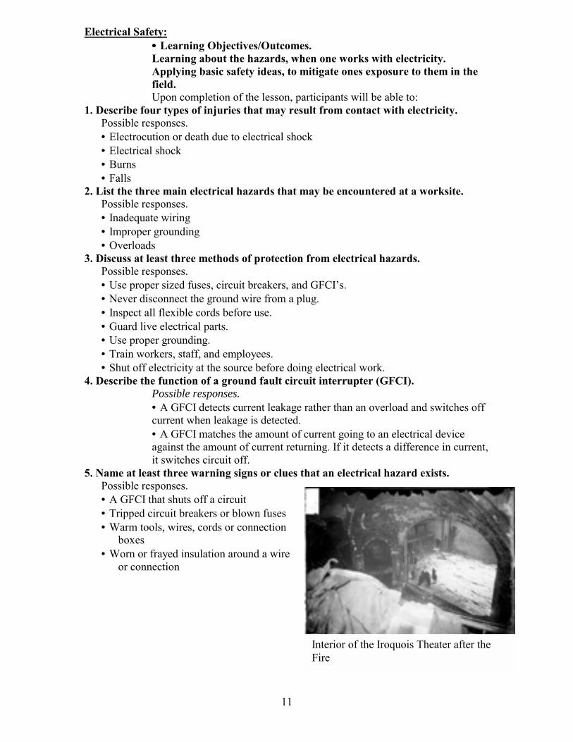
Interior of the Iroquois Theater after the Fire
Electrical Safety: • • • • Learning Objectives/Outcomes. Learning about the hazards, when one works with electricity. Applying basic safety ideas, to mitigate ones exposure to them in the field. Upon completion of the lesson, participants will be able to:
1. Describe four types of injuries that may result from contact with electricity. Possible responses. • Electrocution or death due to electrical shock • Electrical shock • Burns • Falls
2. List the three main electrical hazards that may be encountered at a worksite. Possible responses. • Inadequate wiring • Improper grounding • Overloads
3. Discuss at least three methods of protection from electrical hazards. Possible responses. • Use proper sized fuses, circuit breakers, and GFCIs. • Never disconnect the ground wire from a plug. • Inspect all flexible cords before use. • Guard live electrical parts. • Use proper grounding. • Train workers, staff, and employees. • Shut off electricity at the source before doing electrical work.
4. Describe the function of a ground fault circuit interrupter (GFCI). Possible responses. • A GFCI detects current leakage rather than an overload and switches off current when leakage is detected. • A GFCI matches the amount of current going to an electrical device against the amount of current returning. If it detects a difference in current, it switches circuit off.
5. Name at least three warning signs or clues that an electrical hazard exists. Possible responses. • A GFCI that shuts off a circuit • Tripped circuit breakers or blown fuses • Warm tools, wires, cords or connection
boxes • Worn or frayed insulation around a wire
or connection

12
13
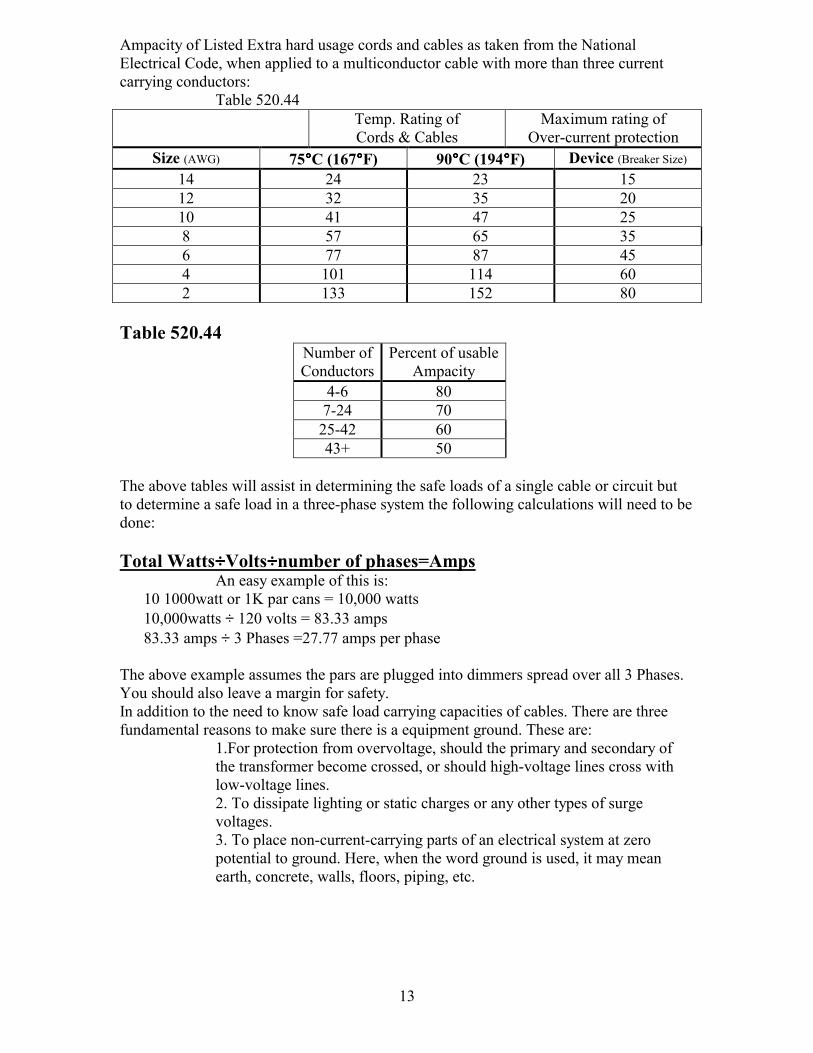
Ampacity of Listed Extra hard usage cords and cables as taken from the National Electrical Code, when applied to a multiconductor cable with more than three current carrying conductors:
Table 520.44 Temp. Rating of
Cords & Cables Maximum rating of
Over-current protection Size (AWG) 75°°°°C (167°°°°F) 90°°°°C (194°°°°F) Device (Breaker Size)
14 24 23 15 12 32 35 20 10 41 47 25 8 57 65 35 6 77 87 45 4 101 114 60 2 133 152 80
Table 520.44
Number of Conductors
Percent of usableAmpacity
4-6 80 7-24 70 25-42 60 43+ 50
The above tables will assist in determining the safe loads of a single cable or circuit but to determine a safe load in a three-phase system the following calculations will need to be done: Total Watts÷÷÷÷Volts÷÷÷÷number of phases=Amps
An easy example of this is: 10 1000watt or 1K par cans = 10,000 watts 10,000watts ÷ 120 volts = 83.33 amps 83.33 amps ÷ 3 Phases =27.77 amps per phase
The above example assumes the pars are plugged into dimmers spread over all 3 Phases. You should also leave a margin for safety. In addition to the need to know safe load carrying capacities of cables. There are three fundamental reasons to make sure there is a equipment ground. These are:
1.For protection from overvoltage, should the primary and secondary of the transformer become crossed, or should high-voltage lines cross with low-voltage lines. 2. To dissipate lighting or static charges or any other types of surge voltages. 3. To place non-current-carrying parts of an electrical system at zero potential to ground. Here, when the word ground is used, it may mean earth, concrete, walls, floors, piping, etc.
14
Electrical Code: Sections of the Chicago Electrical code that pertain to the theatrical trade. Chapters 1-4, general sections
Chapter 5: Special occupancies, 518 Places of Assembly, 520 Theatres, Audiences areas of motion pictures and TV studios. 525 Carnivals, Circuses and Fairs. 530 Motion Picture Studios and other locations.
National Electrical Code NEC 2002 Chapter 2 Wiring and Protection, Articles 200, 210, 220, 250. Chapter 4 Equipment General Use, Articles 400, 410. Chapter 5 Special Occupancies, Article 520, 530, 540 Chapter 6 Special Equipment, Article 630, 640 Chapter 7 Special Conditions, Article 700, 701
Electricity:
• • • • Learning Objectives/Outcomes. Learning the basic concepts of what electricity is and its components. To facilitate ones ability to perform the mathematics to compute loads, wattages and the like in order to safely assembly, determine electrical needs and solve problems
The law of electrical charges: Like Charges repel, opposite charges attract. So therefore electricity is the flow of these free electrons in a wire. This flow is described as current. Benjamin Franklin made the designation of positive and negative with the knowledge of electrons (-) and protons (+). Is defined using these terms, Coulomb and Electrostatic Field Sources of Electricity The three basic sources of electricity that a stagehand deals with are a battery source and generated. The generated may be a field type of generator used on location or the type that is used to generate power for an entire city. Battery sources are used in a theatrical sense primarily for handheld lighting sources that need illumination. Most all power that we use is connected to a building service that in turn receives its source for a commercial power provider such as Com ED. On other occasion when not enough power can be provided by the building or in a remote location were there is no electricity. A portable generator will be brought in to provide electricity to the lighting, and sound packages. The Electrostatic Field The fundamental characteristic of an electric charge is its ability to exert a force. This force is present within the electrostatic field surrounding every charged object. When two objects of opposite polarity are brought near each other, the electrostatic field is concentrated in the area between them. If an electron is released between these two objects, it will be repelled by the negative and attracted to the positive object. When a charged object retains its charge temporarily, and there is no immediate transfer of electrons to or from it, it is said to be at rest. Electricity at rest is called static electricity Conductors A conductor is a material that easily lets a few electrons move from molecule to molecule (protons/nucleus with and electron orbiting it) to the other molecule.
15
Inexpensive metals with these properties are copper and aluminum. Copper is the prevalent conductor used in the theatrical trade and used extensively in your homes. Article 110.5 states: conductors normally used to carry current shall be of copper unless otherwise provided in the NEC. Where the conductor material is not specified the material and the sizes given in the code shall apply to copper conductors. Where other materials are use, the size shall be changed accordingly. Insulators
An insulator does not easily release electrons to move about. Which is why plastic is used as a typical insulator around copper wire. However, to have a flexible insulator, rubber is one type used, such as the coating on feeder cable. The Coulomb/Measuring Current The Coulomb is the magnitude or quantity of electric charge a body possesses which is determined by the number of electrons compared with the number of protons within the body. The symbol for the magnitude of the electric charge is Q, expressed in units of coulombs C. A coulomb is the unit for counting electrons, using the coulomb to count for 1 second equals 1 ampere and becomes a multiplier for each second. Therefore 2 coulombs per second equals 2 ampere. 1ampere= 1 coulomb per second The convention to represent current with a symbol or letter which is I; were I designates the units of ampere, as in I=1 ampere as in the above example or I=15 amps (amperes). An example of current flow is the use of a battery for this. Batteries are devices that demonstrate the flow of current with a positive and negative terminal, which are formed into contacts. When a wire is connected to each terminal, the positive and negative terminals, a closed circuit is formed causing current to flow. A battery is dead or drained when enough electrons have flowed form the negative to positive terminals, causing the current to cease flowing. Current flow can be described as a potential inducing the free electrons to forcibly move through a copper wire. To do so a batter needs to be connected across the two ends of the wire, an applied voltage of a battery 1.5V forces the free electrons to move. The current is the drift of these electrons moving from the negative charge side of the battery through the wire and back to the positive side of the battery. Potential Difference/ Measuring Voltage Because of the force of its electrostatic field, an electric charge has the ability to do the work of moving another charge by attraction or repulsion. The ability of a charge to do work is called its potential. When one charge is different from the other, there must be a difference in potential between them. The sum of the differences of potential of all the charges in the electrostatic field is referred to as electromotive force emf. The basic unit of potential difference is the volt. The symbol for potential difference is V, indicating the ability to do the work of forcing electrons to move in a circuit. If a voltage is applied, and a path is provided which could be a piece of wire, then a current will flow. If you produce a path or wire and do not apply any voltage, then there will be no current. So providing a path will cause a potential difference that is called voltage or volt. The strength of electrons moving through a conductor or from a generating source is measured in voltage. So the higher the pressure to push electrons generates a higher voltage. The lower the pressure, the lower the voltage.
16
Article 110.4 states: voltages considered shall be that at which the circuit operates. The voltage rating of electrical equipment shall not be less than the nominal voltage of a circuit to which it is connected. Measuring Resistance Amperes (current) and voltage (electrical pressure) are related due to the fact the some wires let more current flow than others. A wire that does not let very much current flow has high resistance. Resistance has a symbol of R when used to express this quantity. The resistance is related to how much the current I we get from a given voltage E by Ohms Law. Given at least two values the third may be found using this formula:
Ohms law states: I=E / R or E=I*R and R=E/I If I is measured in ampere, and V emf in volts, then we say that R is units of resistance ohms”. For example: a 1 volt battery, and a wire with a resistance of 1 ohm, then the current that at the batterys terminal is;
I=E÷R 1 volt-emf (E)/ 1ohm (R)= 1 ampere (I)
Knowing two of the three values, the third may be calculated. Following are some examples of uses of the above formula:
I=E ÷R = 100V ÷50Ω=2A I=E ÷R =100V ÷100Ω= 1A I=E ÷R =200 ÷50Ω=4A The following example uses a heater element of 20 and 40ohms:
20 ohms on 120 volts I=V/R= 120V/20Ω=6A 40 ohms on 120 volts I=V/R= 120V/40Ω=3A 20 ohms on 240 volts I=V/R= 240V/20Ω=12A 40 ohms on 240 volts I=V/R= 240V/40Ω=6A
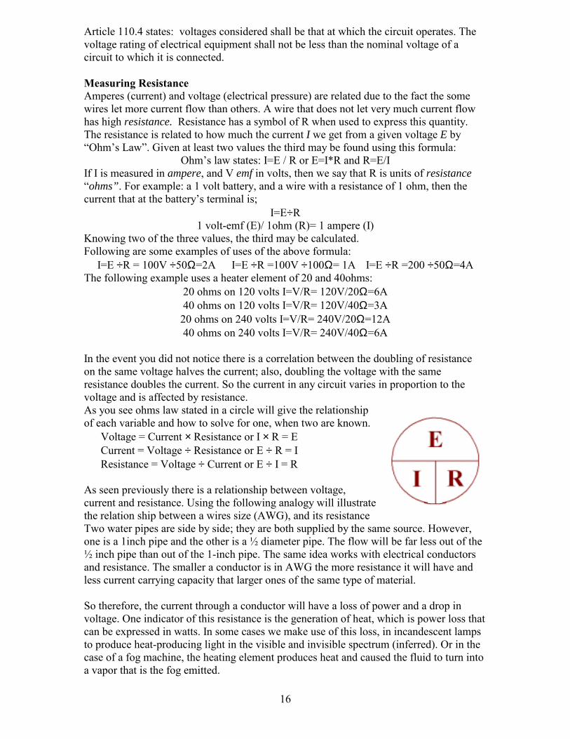
In the event you did not notice there is a correlation between the doubling of resistance on the same voltage halves the current; also, doubling the voltage with the same resistance doubles the current. So the current in any circuit varies in proportion to the voltage and is affected by resistance. As you see ohms law stated in a circle will give the relationship of each variable and how to solve for one, when two are known.
Voltage = Current × Resistance or I × R = E Current = Voltage ÷ Resistance or E ÷ R = I Resistance = Voltage ÷ Current or E ÷ I = R
As seen previously there is a relationship between voltage, current and resistance. Using the following analogy will illustrate the relation ship between a wires size (AWG), and its resistance Two water pipes are side by side; they are both supplied by the same source. However, one is a 1inch pipe and the other is a ½ diameter pipe. The flow will be far less out of the ½ inch pipe than out of the 1-inch pipe. The same idea works with electrical conductors and resistance. The smaller a conductor is in AWG the more resistance it will have and less current carrying capacity that larger ones of the same type of material. So therefore, the current through a conductor will have a loss of power and a drop in voltage. One indicator of this resistance is the generation of heat, which is power loss that can be expressed in watts. In some cases we make use of this loss, in incandescent lamps to produce heat-producing light in the visible and invisible spectrum (inferred). Or in the case of a fog machine, the heating element produces heat and caused the fluid to turn into a vapor that is the fog emitted.
17
The previous two examples illustrate two uses of harnessing this resistance, however for circuits that carry current, resistance needs to be kept to a minimum.
1.The resistance of a conductor is directly proportional to its length. 2.The resistance of a conductor is inversely proportional to its cross sectional area.
3. The resistance of a conductor of a given length and cross sectional area depends upon the material of which its composed.
4. Temperature affects resistance. All pure metals increase in resistance with an increase in temperature, but this increase is not linear.
Watts Ohms Law as defined above may also be applied to electric power, which is our primary concern. Defining Ohms Law when used with electric power is: electric power P used in any part of a circuit is equal to the current I in that part multiplied by the voltage V across that part of the circuit. Its formula being: P=VI
P= power expressed as W or Watts V=voltage, V I =current, A
To express the formula in the other two transpositions:
I = P ÷ E E= P ÷ I
Or stated another way W=V×A substituting Watts for Power and A to express current. This transposition allows one to easily solve for problems using terms that express the ratings that we work with in the theatrical trade. A lamp is given a value in watts, voltage is treated as 110v and a breaker is rated in amperes or amps. Direct and Alternating Current and Voltages Direct current (DC) is current that moves through a conductor or circuit in one direction. The reason for the unidirectional current is that voltage sources such as cells and batteries maintain the same polarity of output voltage. The voltage supplied by these sources is call direct current, or simply DC voltage. A DC voltage source can easily change the amount of its output voltage and maintain is direction of current flow assuming it polarity stays the same. If you need to know more about DC Direct current can be generated using the same basic components as found in a DC motor. A motor converts electric energy into rotary mechanical energy. While a generator, converts rotary mechanical energy into electric energy. The mechanical energy
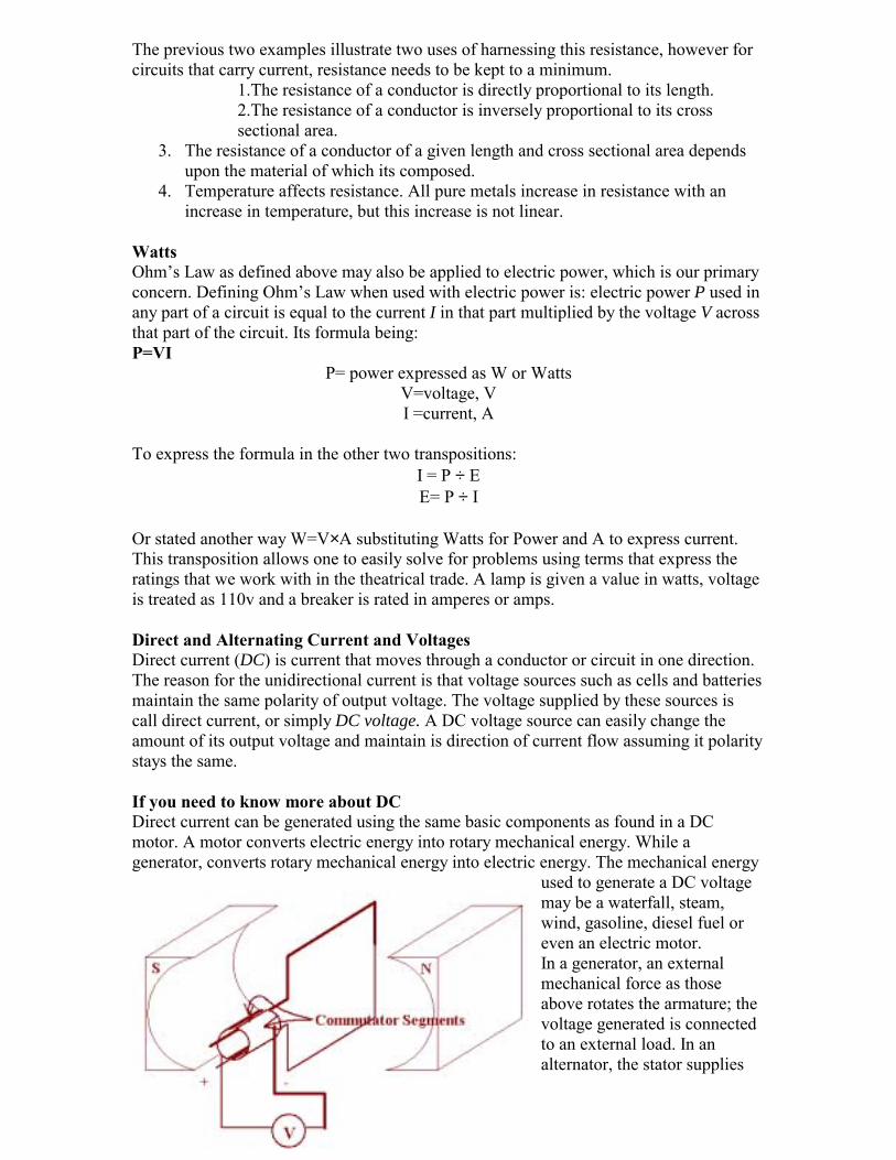
used to generate a DC voltage may be a waterfall, steam, wind, gasoline, diesel fuel or even an electric motor. In a generator, an external mechanical force as those above rotates the armature; the voltage generated is connected to an external load. In an alternator, the stator supplies

18
the field of the magnetic lines of force. The rotor, or armature, as it is called in a DC generator is the part that the emf is generated. Also in a DC generator a means is needed to collect the emf from the generator in one direction only. This is accomplished by the means of a commutator, which is split lengthwise and the two halves are insulted from each other. The commutator consists of copper segments, on pair for each armature coil. Each commutator segment is then insulated from the other and from the armature shaft. These commutator segments make contact with two stationary brushes. These brushes are then spring-mounted to slide or brush against the commutator as it rotates. Which in turn provide a connection between the armature coils and the external load. Much like a common DC motor used in various toys. When the armature coil cuts across the magnetic field it produces voltage, if a complete path is present. Current will move through the armature coil through to the commutator to a segment that is in contact with each of the brushes. Because of the constant contact between a segment of the commutator and the brushes the armature coil is always cutting across the magnetic field in the same direction. Therefore both brushes have a constant polarity and a pulsating direct current is delivered to the external load and zero volts will be reached more than once for each revolution. By using a higher number of armature coils a smoother waveform can be obtained for the DC voltage. Alternating current Alternating current (ac) is voltage source that periodically reverses or alternates in polarity. Therefore, the resulting current also periodically reverses direction. In terms of current flow, it flows from the positive terminal of the voltage source (generator) through the circuit, and back to the negative terminal, but when the generator alternates in polarity, the current must reverse it direction. These voltage and current reversals happen many times a second in these systems. Obviously the power line used in homes is a common example of this. Alternating-current generators are commonly knows as alternators, are used to generate AC voltage. As a rule an alternator has the winding stationary termed stator. The rotating portion or rotor is the DC part of the alternator and receives it voltage from an exciter that is mounted on the alternator and the armature of which is driven by the rotor shaft of the alternator. The DC portion of the alternator will be stationary with only the AC portion rotating, this simplifies the explanation to follow. The AC voltage is transmitted using slip rings and brushes.
The advantage that AC current has over DC current is the ease of transmission. When there is a need of a higher or lower voltage, simple step-up or step-down transformer is used. To do the sample with DC a motor generator set is need to change voltages or to convert to AC. If it is necessary to convert back to DC rectifiers are needed to do so.
19
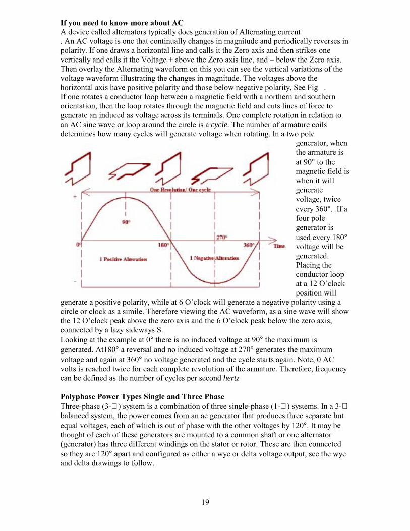
If you need to know more about AC A device called alternators typically does generation of Alternating current . An AC voltage is one that continually changes in magnitude and periodically reverses in polarity. If one draws a horizontal line and calls it the Zero axis and then strikes one vertically and calls it the Voltage + above the Zero axis line, and below the Zero axis. Then overlay the Alternating waveform on this you can see the vertical variations of the voltage waveform illustrating the changes in magnitude. The voltages above the horizontal axis have positive polarity and those below negative polarity, See Fig . If one rotates a conductor loop between a magnetic field with a northern and southern orientation, then the loop rotates through the magnetic field and cuts lines of force to generate an induced as voltage across its terminals. One complete rotation in relation to an AC sine wave or loop around the circle is a cycle. The number of armature coils determines how many cycles will generate voltage when rotating. In a two pole
generator, when the armature is at 90° to the magnetic field is when it will generate voltage, twice every 360°. If a four pole generator is used every 180° voltage will be generated. Placing the conductor loop at a 12 Oclock position will
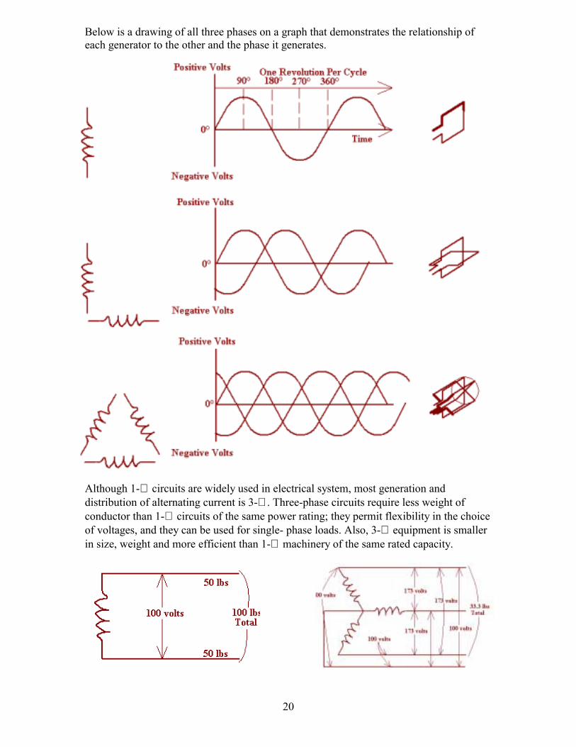
generate a positive polarity, while at 6 Oclock will generate a negative polarity using a circle or clock as a simile. Therefore viewing the AC waveform, as a sine wave will show the 12 Oclock peak above the zero axis and the 6 Oclock peak below the zero axis, connected by a lazy sideways S. Looking at the example at 0° there is no induced voltage at 90° the maximum is generated. At180° a reversal and no induced voltage at 270° generates the maximum voltage and again at 360° no voltage generated and the cycle starts again. Note, 0 AC volts is reached twice for each complete revolution of the armature. Therefore, frequency can be defined as the number of cycles per second hertz Polyphase Power Types Single and Three Phase Three-phase (3-∅ ) system is a combination of three single-phase (1-∅ ) systems. In a 3-∅ balanced system, the power comes from an ac generator that produces three separate but equal voltages, each of which is out of phase with the other voltages by 120°. It may be thought of each of these generators are mounted to a common shaft or one alternator (generator) has three different windings on the stator or rotor. These are then connected so they are 120° apart and configured as either a wye or delta voltage output, see the wye and delta drawings to follow.
20
Below is a drawing of all three phases on a graph that demonstrates the relationship of each generator to the other and the phase it generates.
Although 1-∅ circuits are widely used in electrical system, most generation and distribution of alternating current is 3-∅ . Three-phase circuits require less weight of conductor than 1-∅ circuits of the same power rating; they permit flexibility in the choice of voltages, and they can be used for single- phase loads. Also, 3-∅ equipment is smaller in size, weight and more efficient than 1-∅ machinery of the same rated capacity.
21
Fig 1 Fig 2
Fig 3. Fig 4.
Fig 5.
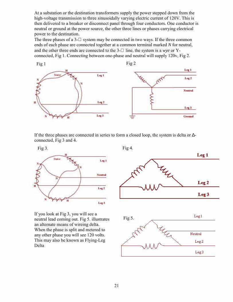
At a substation or the destination transformers supply the power stepped down from the high-voltage transmission to three sinusoidally varying electric current of 120V. This is then delivered to a breaker or disconnect panel through four conductors. One conductor is neutral or ground at the power source, the other three lines or phases carrying electrical power to the destination. The three phases of a 3-∅ system may be connected in two ways. If the three common ends of each phase are connected together at a common terminal marked N for neutral, and the other three ends are connected to the 3-∅ line, the system is a wye or Y-connected, Fig 1. Connecting between one-phase and neutral will supply 120v, Fig 2.
If the three phases are connected in series to form a closed loop, the system is delta or ∆-connected, Fig 3 and 4.
If you look at Fig 3, you will see a neutral lead coming out. Fig 5. illustrates an alternate means of wireing delta. When the phase is split and metered to any other phase you will see 120 volts. This may also be known as Flying-Leg Delta

22
23
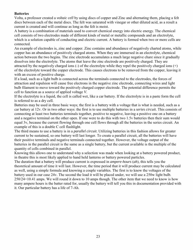
Batteries Volta, a professor created a voltaic cell by using discs of copper and Zinc and alternating them, placing a felt discs between each of the metal discs. The felt was saturated with vinegar or other diluted acid, as a result a current is created and will continue as long as the felt is moist. A battery is a combination of materials used to convert chemical energy into electric energy. The chemical cell consists of two electrodes made of different kinds of metal or metallic compounds and an electrolyte, which is a solution capable of conducting and electric current. A battery is formed when two or more cells are connected. An example of electrodes is, zinc and copper. Zinc contains and abundance of negatively charted atoms, while copper has an abundance of positively charged atoms. When they are immersed in an electrolyte, chemical action between the two begins. The zinc electrode accumulates a much large negative chare since it gradually dissolves into the electrolyte. The atoms that leave the zinc electrode are positively charged. They are attracted by the negatively charged ions (-) of the electrolyte while they repel the positively charged ions (+) of the electrolyte toward the copper electrode. This causes electrons to be removed from the copper, leaving it with an excess of positive charge. If a load, such as a light bulb is connected across the terminals connected to the electrodes, the forces of attraction and repulsion will cause free electrons in the negative zinc electrode, connecting wires and light bulb filament to move toward the positively charged copper electrode. The potential difference permits the cell to function as a source of applied voltage V. If the electrolyte is a liquid, the cell is called wet, like a car battery. If the electrolyte is in a paste form the cell is referred to as a dry cell. Batteries may be used in three basic ways; the first is a battery with a voltage that is what is needed, such as a car battery at 12v. Or in two other ways: the first is to use multiple batteries in a series circuit. This consists of connecting at least two batteries terminals together, positive to negative, leaving a positive one on a battery and a negative terminal on the other open. If one were to do this with two 1.5v batteries then their sum would equal 3v, because the current flowing through one cell flows through all the batteries in the series circuit. An example of this is a double C cell flashlight. The third means to use a battery is in a parallel circuit. Utilizing batteries in this fashion allows for greater current to be sustained, so one battery will last longer. To create a parallel circuit, all the batteries will have their positive terminals and negative terminals connected together. However, the voltage output of the batteries in the parallel circuit is the same as a single battery, but the current available is the multiple of the quantity of cells combined in parallel. Knowing this allows one to understand why a selection was made when looking at a battery powered product, in theatre this is most likely applied to hand held lanterns or battery powered particles. The duration that a battery will produce current is expressed in ampere-hours (ah), this tells you the theoretical amount of time it will last. However, the time period that it will produce current may be calculated as well, using a simple formula and knowing a couple variables. The first is to know the voltages of the battery used in our case 24v. The second the load it will be placed under, we will use a 250w light bulb. 250/24=10.41 amps. We will round it down to 10 amps though. The other item that we need to know is how many ampere hours is the batter rated for, usually the battery will tell you this in documentation provided with it. Our particular battery has a life of 7-Ah.
24
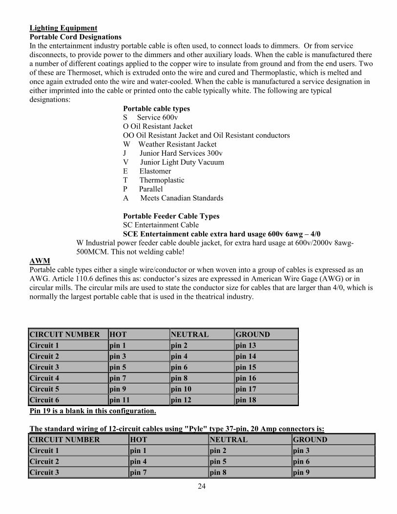
Lighting Equipment Portable Cord Designations In the entertainment industry portable cable is often used, to connect loads to dimmers. Or from service disconnects, to provide power to the dimmers and other auxiliary loads. When the cable is manufactured there a number of different coatings applied to the copper wire to insulate from ground and from the end users. Two of these are Thermoset, which is extruded onto the wire and cured and Thermoplastic, which is melted and once again extruded onto the wire and water-cooled. When the cable is manufactured a service designation in either imprinted into the cable or printed onto the cable typically white. The following are typical designations:
Portable cable types S Service 600v O Oil Resistant Jacket OO Oil Resistant Jacket and Oil Resistant conductors
W Weather Resistant Jacket J Junior Hard Services 300v V Junior Light Duty Vacuum E Elastomer T Thermoplastic P Parallel A Meets Canadian Standards
Portable Feeder Cable Types SC Entertainment Cable SCE Entertainment cable extra hard usage 600v 6awg 4/0
W Industrial power feeder cable double jacket, for extra hard usage at 600v/2000v 8awg-500MCM. This not welding cable!
AWM Portable cable types either a single wire/conductor or when woven into a group of cables is expressed as an AWG. Article 110.6 defines this as: conductors sizes are expressed in American Wire Gage (AWG) or in circular mills. The circular mils are used to state the conductor size for cables that are larger than 4/0, which is normally the largest portable cable that is used in the theatrical industry. CIRCUIT NUMBER HOT NEUTRAL GROUND Circuit 1 pin 1 pin 2 pin 13 Circuit 2 pin 3 pin 4 pin 14 Circuit 3 pin 5 pin 6 pin 15 Circuit 4 pin 7 pin 8 pin 16 Circuit 5 pin 9 pin 10 pin 17 Circuit 6 pin 11 pin 12 pin 18 Pin 19 is a blank in this configuration. The standard wiring of 12-circuit cables using "Pyle" type 37-pin, 20 Amp connectors is: CIRCUIT NUMBER HOT NEUTRAL GROUND Circuit 1 pin 1 pin 2 pin 3 Circuit 2 pin 4 pin 5 pin 6 Circuit 3 pin 7 pin 8 pin 9
25
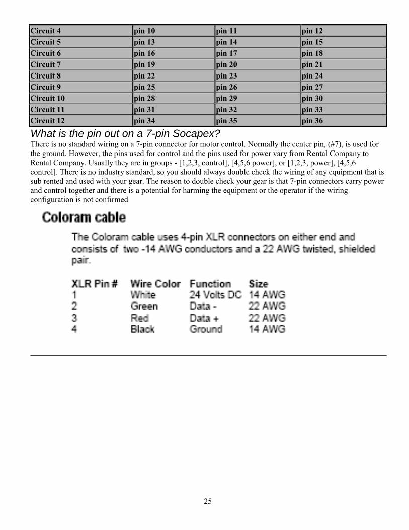
Circuit 4 pin 10 pin 11 pin 12 Circuit 5 pin 13 pin 14 pin 15 Circuit 6 pin 16 pin 17 pin 18 Circuit 7 pin 19 pin 20 pin 21 Circuit 8 pin 22 pin 23 pin 24 Circuit 9 pin 25 pin 26 pin 27 Circuit 10 pin 28 pin 29 pin 30 Circuit 11 pin 31 pin 32 pin 33 Circuit 12 pin 34 pin 35 pin 36
What is the pin out on a 7-pin Socapex? There is no standard wiring on a 7-pin connector for motor control. Normally the center pin, (#7), is used for the ground. However, the pins used for control and the pins used for power vary from Rental Company to Rental Company. Usually they are in groups - [1,2,3, control], [4,5,6 power], or [1,2,3, power], [4,5,6 control]. There is no industry standard, so you should always double check the wiring of any equipment that is sub rented and used with your gear. The reason to double check your gear is that 7-pin connectors carry power and control together and there is a potential for harming the equipment or the operator if the wiring configuration is not confirmed
26
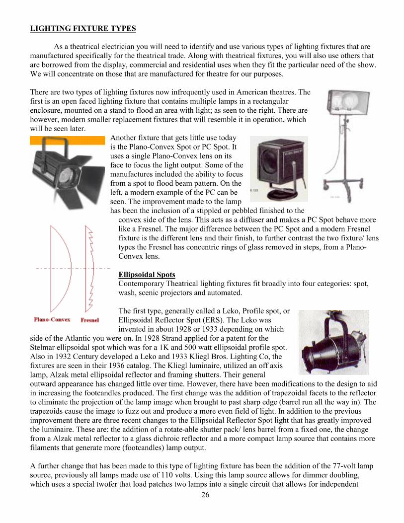
LIGHTING FIXTURE TYPES As a theatrical electrician you will need to identify and use various types of lighting fixtures that are manufactured specifically for the theatrical trade. Along with theatrical fixtures, you will also use others that are borrowed from the display, commercial and residential uses when they fit the particular need of the show. We will concentrate on those that are manufactured for theatre for our purposes. There are two types of lighting fixtures now infrequently used in American theatres. The first is an open faced lighting fixture that contains multiple lamps in a rectangular enclosure, mounted on a stand to flood an area with light; as seen to the right. There are however, modern smaller replacement fixtures that will resemble it in operation, which will be seen later.
Another fixture that gets little use today is the Plano-Convex Spot or PC Spot. It uses a single Plano-Convex lens on its face to focus the light output. Some of the manufactures included the ability to focus from a spot to flood beam pattern. On the left, a modern example of the PC can be seen. The improvement made to the lamp has been the inclusion of a stippled or pebbled finished to the
convex side of the lens. This acts as a diffuser and makes a PC Spot behave more like a Fresnel. The major difference between the PC Spot and a modern Fresnel fixture is the different lens and their finish, to further contrast the two fixture/ lens types the Fresnel has concentric rings of glass removed in steps, from a Plano-Convex lens. Ellipsoidal Spots Contemporary Theatrical lighting fixtures fit broadly into four categories: spot, wash, scenic projectors and automated. The first type, generally called a Leko, Profile spot, or Ellipsoidal Reflector Spot (ERS). The Leko was invented in about 1928 or 1933 depending on which
side of the Atlantic you were on. In 1928 Strand applied for a patent for the Stelmar ellipsoidal spot which was for a 1K and 500 watt ellipsoidal profile spot. Also in 1932 Century developed a Leko and 1933 Kliegl Bros. Lighting Co, the fixtures are seen in their 1936 catalog. The Kliegl luminaire, utilized an off axis lamp, Alzak metal ellipsoidal reflector and framing shutters. Their general outward appearance has changed little over time. However, there have been modifications to the design to aid in increasing the footcandles produced. The first change was the addition of trapezoidal facets to the reflector to eliminate the projection of the lamp image when brought to past sharp edge (barrel run all the way in). The trapezoids cause the image to fuzz out and produce a more even field of light. In addition to the previous improvement there are three recent changes to the Ellipsoidal Reflector Spot light that has greatly improved the luminaire. These are: the addition of a rotate-able shutter pack/ lens barrel from a fixed one, the change from a Alzak metal reflector to a glass dichroic reflector and a more compact lamp source that contains more filaments that generate more (footcandles) lamp output. A further change that has been made to this type of lighting fixture has been the addition of the 77-volt lamp source, previously all lamps made use of 110 volts. Using this lamp source allows for dimmer doubling, which uses a special twofer that load patches two lamps into a single circuit that allows for independent
27
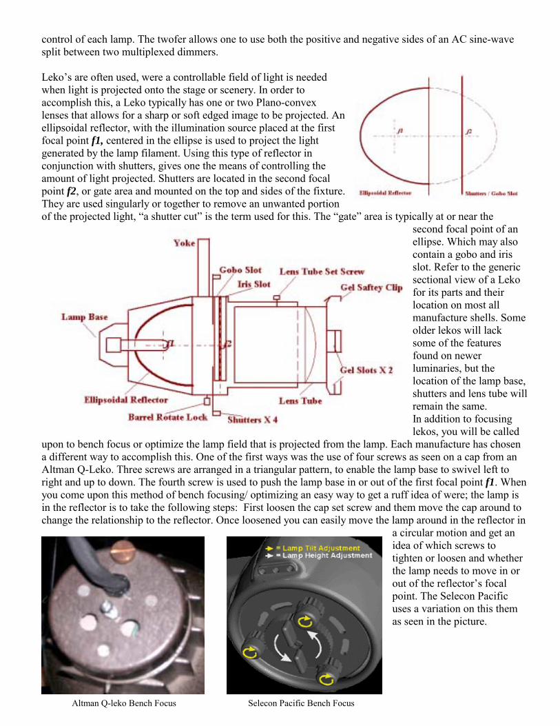
control of each lamp. The twofer allows one to use both the positive and negative sides of an AC sine-wave split between two multiplexed dimmers. Lekos are often used, were a controllable field of light is needed when light is projected onto the stage or scenery. In order to accomplish this, a Leko typically has one or two Plano-convex lenses that allows for a sharp or soft edged image to be projected. An ellipsoidal reflector, with the illumination source placed at the first focal point f1, centered in the ellipse is used to project the light generated by the lamp filament. Using this type of reflector in conjunction with shutters, gives one the means of controlling the amount of light projected. Shutters are located in the second focal point f2, or gate area and mounted on the top and sides of the fixture. They are used singularly or together to remove an unwanted portion of the projected light, a shutter cut is the term used for this. The gate area is typically at or near the
second focal point of an ellipse. Which may also contain a gobo and iris slot. Refer to the generic sectional view of a Leko for its parts and their location on most all manufacture shells. Some older lekos will lack some of the features found on newer luminaries, but the location of the lamp base, shutters and lens tube will remain the same. In addition to focusing lekos, you will be called
upon to bench focus or optimize the lamp field that is projected from the lamp. Each manufacture has chosen a different way to accomplish this. One of the first ways was the use of four screws as seen on a cap from an Altman Q-Leko. Three screws are arranged in a triangular pattern, to enable the lamp base to swivel left to right and up to down. The fourth screw is used to push the lamp base in or out of the first focal point f1. When you come upon this method of bench focusing/ optimizing an easy way to get a ruff idea of were; the lamp is in the reflector is to take the following steps: First loosen the cap set screw and them move the cap around to change the relationship to the reflector. Once loosened you can easily move the lamp around in the reflector in
a circular motion and get an idea of which screws to tighten or loosen and whether the lamp needs to move in or out of the reflectors focal point. The Selecon Pacific uses a variation on this them as seen in the picture.
Selecon Pacific Bench Focus Altman Q-leko Bench Focus
28
Another popular method was a joystick; it usually consists of a single knob that is loosened, with the lamp base attached to it. In the case of the Strand, the joystick is triangular and it was moved around until the lamp output increased. This was done in conjunction with a second setscrew that held the base onto the lamp unit; the secondary setscrew moved the lamp in and out of the first focal point f1. When the brightest output reached, both setscrews are tightened down to hold the new bench focus.
The most prevalent way to do the bench focus is the use of two different knobs as seen on the ETC Source Four. The center-knurled knob, controls the in/ out movement of the lamp in relation to the focal point f1 or the Peak/ Flat adjustment. The other, which looks like a wing nut, moves the lamp in a circular pattern within the reflector to help center the lamp. If this method is used either the in/ out or the left to right will need to
be checked once the other is tightened to assure a good bench focus.
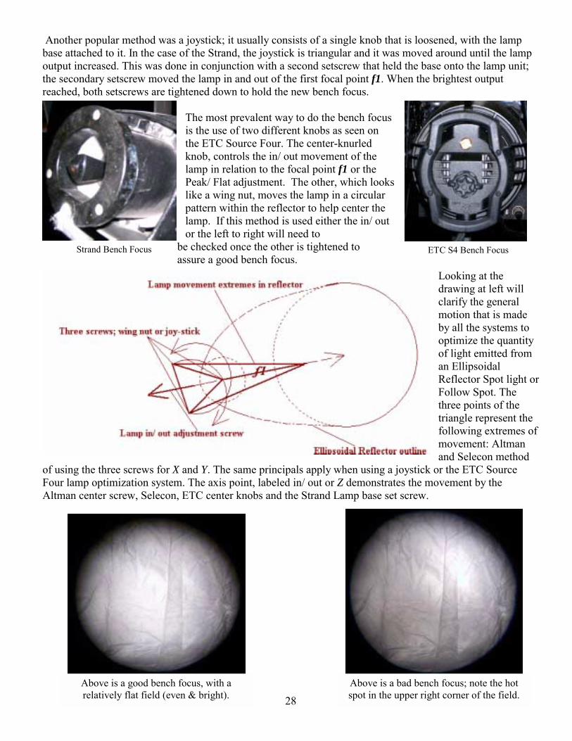
Looking at the drawing at left will clarify the general motion that is made by all the systems to optimize the quantity of light emitted from an Ellipsoidal Reflector Spot light or Follow Spot. The three points of the triangle represent the following extremes of movement: Altman and Selecon method
of using the three screws for X and Y. The same principals apply when using a joystick or the ETC Source Four lamp optimization system. The axis point, labeled in/ out or Z demonstrates the movement by the Altman center screw, Selecon, ETC center knobs and the Strand Lamp base set screw.
ETC S4 Bench Focus Strand Bench Focus
Above is a good bench focus, with a relatively flat field (even & bright).
Above is a bad bench focus; note the hot spot in the upper right corner of the field.
29
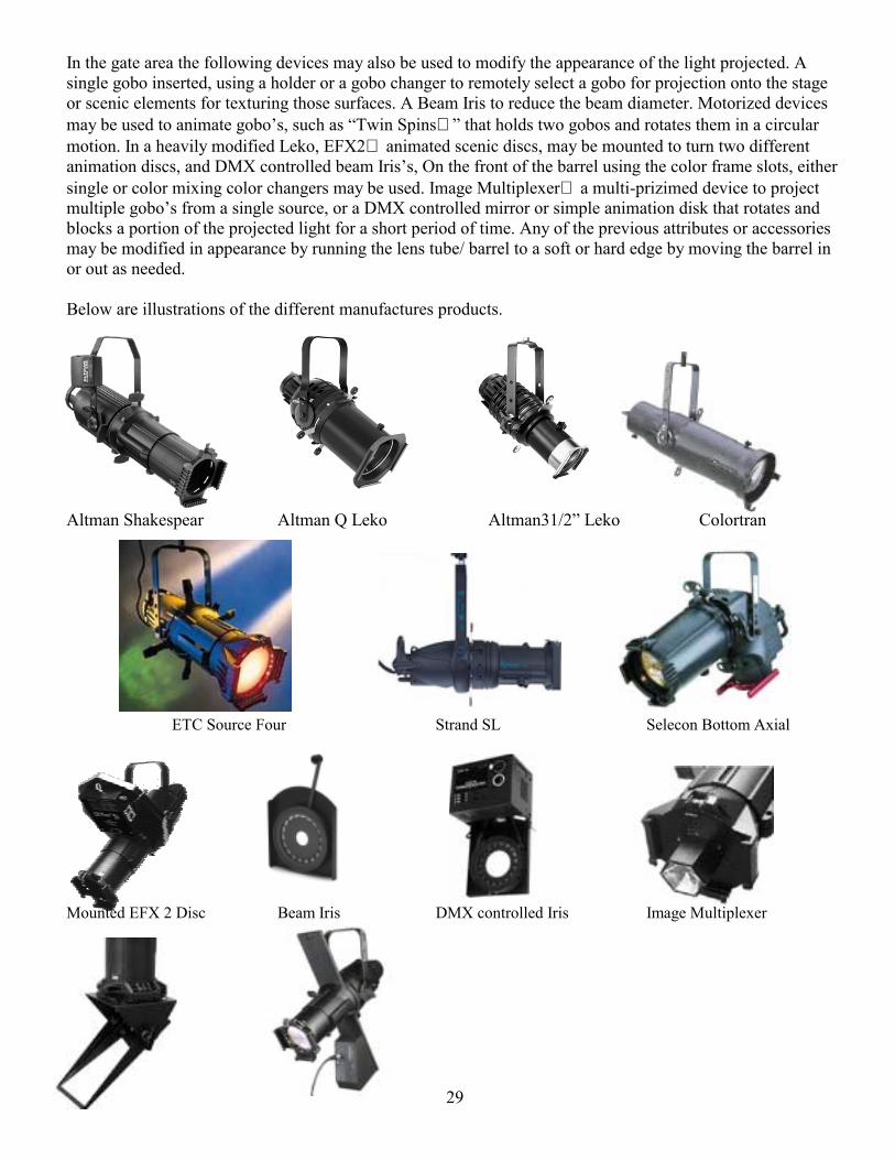
In the gate area the following devices may also be used to modify the appearance of the light projected. A single gobo inserted, using a holder or a gobo changer to remotely select a gobo for projection onto the stage or scenic elements for texturing those surfaces. A Beam Iris to reduce the beam diameter. Motorized devices may be used to animate gobos, such as Twin Spins that holds two gobos and rotates them in a circular motion. In a heavily modified Leko, EFX2 animated scenic discs, may be mounted to turn two different animation discs, and DMX controlled beam Iriss, On the front of the barrel using the color frame slots, either single or color mixing color changers may be used. Image Multiplexer a multi-prizimed device to project multiple gobos from a single source, or a DMX controlled mirror or simple animation disk that rotates and blocks a portion of the projected light for a short period of time. Any of the previous attributes or accessories may be modified in appearance by running the lens tube/ barrel to a soft or hard edge by moving the barrel in or out as needed. Below are illustrations of the different manufactures products.
Altman Shakespear Altman Q Leko Altman31/2 Leko Colortran
ETC Source Four Strand SL Selecon Bottom Axial
Mounted EFX 2 Disc Beam Iris DMX controlled Iris Image Multiplexer
30
DMX Mirror Gobo Changer Lekos are sized either by their beam spread or by the lens focal point. When you are looking at a lens from unit that is older unit the focal point of the lens may be measured using a ruler. To do this, simply hold the lens under a light and measure the flat side of the lens to a tabletop. This measurement will give you the approximate focal length of the lens in the event you need to match it. Such as used in an Altman Q light that uses a double Plano-convex lens tube. In newer units made by ETC and Altman they have adopted a color code system for their lenses, examples of this are seen above. Manufacture/ Name Fixture
Type True Field
Angle Beam Angle Lamp Weight
Altman Q 360 4.5 X 6.5 55° 22° GLC 575 13.5 Altman Q 360 6 X 9 37° 16° GLC 575 14 Altman Q 360 6 X 12 26° 11° GLC 575 15 Altman Q 360 6 X 16 19° 8.5° GLC 575 15 Altman Q 360 6 X 22 11° 8° GLC 575 15 Altman Shakespear 50° 50° 23° GLC 575 15 Altman Shakespear 40° 38° 20° GLC 575 15 Altman Shakespear 30° 28° 13° GLC 575 15 Altman Shakespear 20° 20° 13° GLC 575 15 Altman Shakespear 12° 12° 7° GLC 575 21 Altman Shakespear 10° 10° 7° GLC 575 16 Altman Shakespear 5° 6.9° 5° GLC 575 16 Colortran 5/50 15° 15° 6.8° FLK 575 19.3 Colortran 5/50 20° 20° 8.3° FLK 575 19.7 Colortran 5/50 40° 40° 15° FLK 575 20.3 Colortran 5/50 50° 50° 17.5° FLK 575 20.9 Colortran 5/50 10° 10° 5.8° FLK 575 20.9 Colortran 5/50 5° 5° 3.3° FLK 575 30.1 ETC Source 4 19° 18° 15° HPL 575 14 ETC Source 4 26° 25° 17° HPL 575 14 ETC Source 4 36° 35° 25° HPL 575 14 ETC Source 4 50° 51° 33° HPL 575 14 ETC Source 4 10° 11° 9° HPL 575 15 ETC Source 4 5° 7° 6° HPL 575 19.2 Strand SL 19° - - GLC 575 15.0 Strand SL 26° - - GLC 575 15.0 Strand SL 36° - - GLC 575 15.0 Strand SL 50° - - GLC 575 15.0 Strand SL 10° - - GLC 575 15.0 Strand SL 5° - - GLC 575 17.6 Selecon Pacific 50° - - GLA 575 18.8 Selecon Pacific 40° - - GLA 575 18.8
Beam Size Equivalent 6 X Color Code 19° 6 X 16 Red 26° 6 X 12 Black/Blue 36° 6 X 9 None/White 50° 4.5 X 6.5 Yellow 10° 6 X 22 Large Lens 5° None Really Large Lens

31
Selecon Pacific 30° - - GLA 575 18.8 Selecon Pacific 20° - - GLA 575 18.8
32
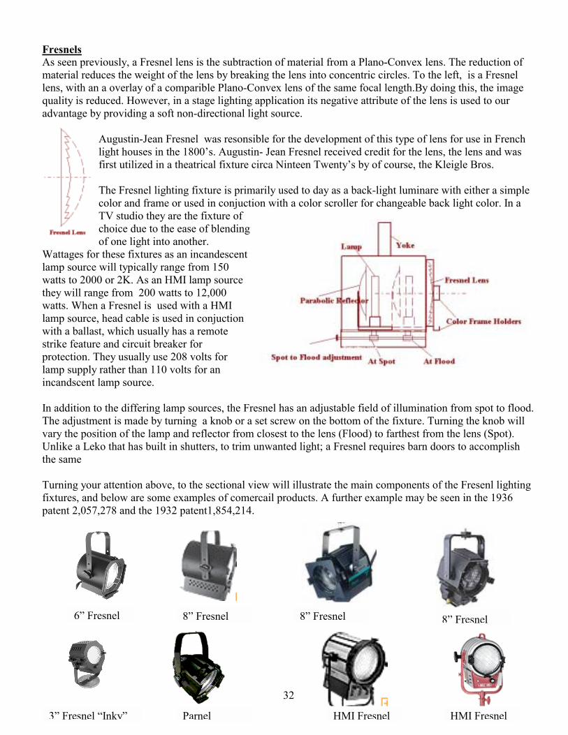
Fresnels As seen previously, a Fresnel lens is the subtraction of material from a Plano-Convex lens. The reduction of material reduces the weight of the lens by breaking the lens into concentric circles. To the left, is a Fresnel lens, with an a overlay of a comparible Plano-Convex lens of the same focal length.By doing this, the image quality is reduced. However, in a stage lighting application its negative attribute of the lens is used to our advantage by providing a soft non-directional light source.
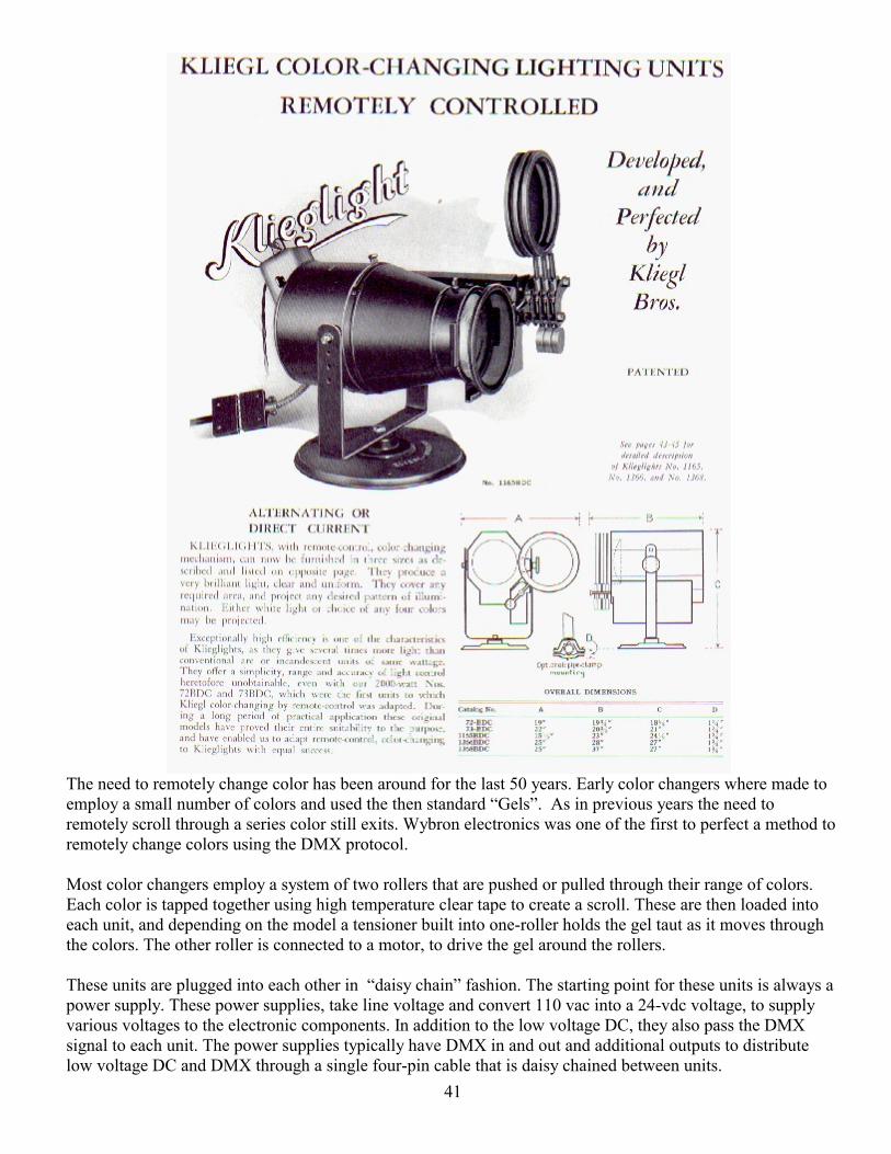
Augustin-Jean Fresnel was resonsible for the development of this type of lens for use in French light houses in the 1800s. Augustin- Jean Fresnel received credit for the lens, the lens and was first utilized in a theatrical fixture circa Ninteen Twentys by of course, the Kleigle Bros. The Fresnel lighting fixture is primarily used to day as a back-light luminare with either a simple color and frame or used in conjuction with a color scroller for changeable back light color. In a TV studio they are the fixture of choice due to the ease of blending of one light into another.
Wattages for these fixtures as an incandescent lamp source will typically range from 150 watts to 2000 or 2K. As an HMI lamp source they will range from 200 watts to 12,000 watts. When a Fresnel is used with a HMI lamp source, head cable is used in conjuction with a ballast, which usually has a remote strike feature and circuit breaker for protection. They usually use 208 volts for lamp supply rather than 110 volts for an incandscent lamp source. In addition to the differing lamp sources, the Fresnel has an adjustable field of illumination from spot to flood. The adjustment is made by turning a knob or a set screw on the bottom of the fixture. Turning the knob will vary the position of the lamp and reflector from closest to the lens (Flood) to farthest from the lens (Spot). Unlike a Leko that has built in shutters, to trim unwanted light; a Fresnel requires barn doors to accomplish the same Turning your attention above, to the sectional view will illustrate the main components of the Fresenl lighting fixtures, and below are some examples of comercail products. A further example may be seen in the 1936 patent 2,057,278 and the 1932 patent1,854,214.
6 Fresnel 8 Fresnel 8 Fresnel 8 Fresnel
3 Fresnel Inky HMI Fresnel HMI FresnelParnel
33
Strand Parblazer
Grand Stage Lighting Sealed Beam Spot
Par Lamps
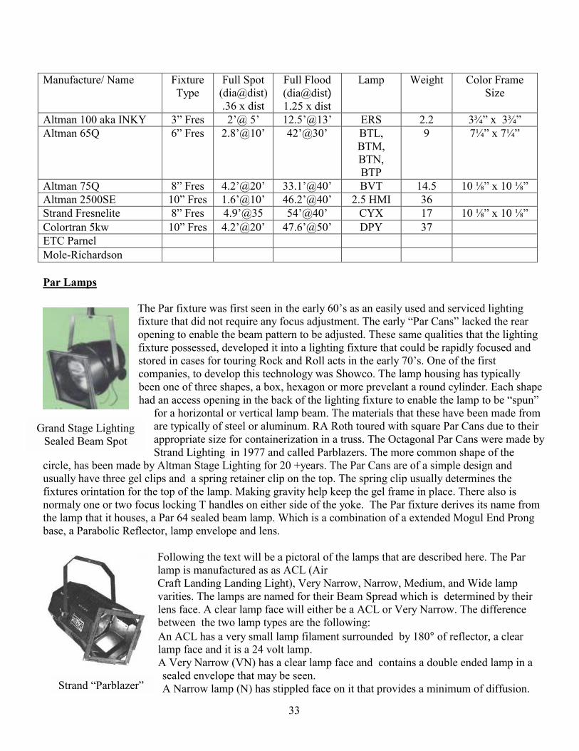
The Par fixture was first seen in the early 60s as an easily used and serviced lighting fixture that did not require any focus adjustment. The early Par Cans lacked the rear opening to enable the beam pattern to be adjusted. These same qualities that the lighting fixture possessed, developed it into a lighting fixture that could be rapidly focused and stored in cases for touring Rock and Roll acts in the early 70s. One of the first companies, to develop this technology was Showco. The lamp housing has typically been one of three shapes, a box, hexagon or more prevelant a round cylinder. Each shape had an access opening in the back of the lighting fixture to enable the lamp to be spun
for a horizontal or vertical lamp beam. The materials that these have been made from are typically of steel or aluminum. RA Roth toured with square Par Cans due to their appropriate size for containerization in a truss. The Octagonal Par Cans were made by Strand Lighting in 1977 and called Parblazers. The more common shape of the
circle, has been made by Altman Stage Lighting for 20 +years. The Par Cans are of a simple design and usually have three gel clips and a spring retainer clip on the top. The spring clip usually determines the fixtures orintation for the top of the lamp. Making gravity help keep the gel frame in place. There also is normaly one or two focus locking T handles on either side of the yoke. The Par fixture derives its name from the lamp that it houses, a Par 64 sealed beam lamp. Which is a combination of a extended Mogul End Prong base, a Parabolic Reflector, lamp envelope and lens.
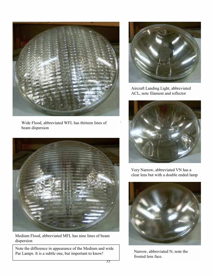
Following the text will be a pictoral of the lamps that are described here. The Par lamp is manufactured as as ACL (Air Craft Landing Landing Light), Very Narrow, Narrow, Medium, and Wide lamp varities. The lamps are named for their Beam Spread which is determined by their lens face. A clear lamp face will either be a ACL or Very Narrow. The difference between the two lamp types are the following: An ACL has a very small lamp filament surrounded by 180° of reflector, a clear lamp face and it is a 24 volt lamp. A Very Narrow (VN) has a clear lamp face and contains a double ended lamp in a sealed envelope that may be seen. A Narrow lamp (N) has stippled face on it that provides a minimum of diffusion.
Manufacture/ Name Fixture Type
Full Spot (dia@dist).36 x dist
Full Flood (dia@dist) 1.25 x dist
Lamp Weight Color Frame Size
Altman 100 aka INKY 3 Fres 2@ 5 12.5@13 ERS 2.2 3¾ x 3¾ Altman 65Q 6 Fres 2.8@10 42@30 BTL,
BTM, BTN, BTP
9 7¼ x 7¼
Altman 75Q 8 Fres 4.2@20 33.1@40 BVT 14.5 10 ⅛ x 10 ⅛ Altman 2500SE 10 Fres 1.6@10 46.2@40 2.5 HMI 36 Strand Fresnelite 8 Fres 4.9@35 54@40 CYX 17 10 ⅛ x 10 ⅛ Colortran 5kw 10 Fres 4.2@20 47.6@50 DPY 37 ETC Parnel Mole-Richardson
34
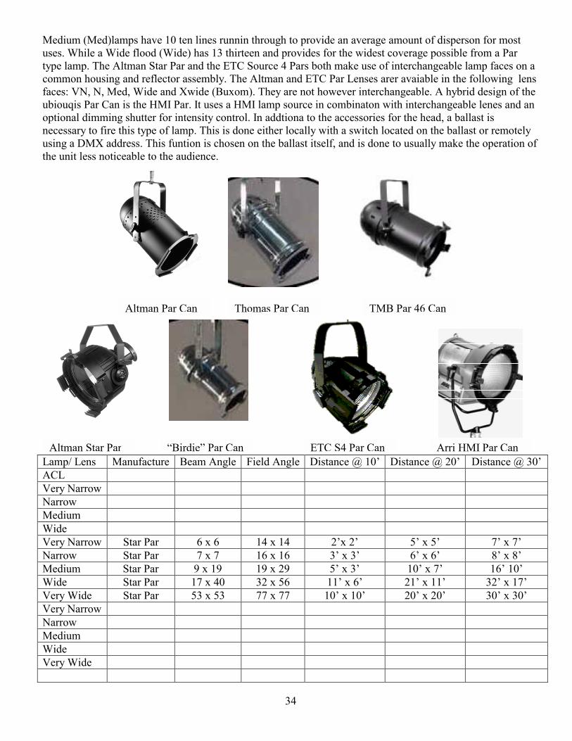
Altman Par Can Thomas Par Can TMB Par 46 Can
Medium (Med)lamps have 10 ten lines runnin through to provide an average amount of disperson for most uses. While a Wide flood (Wide) has 13 thirteen and provides for the widest coverage possible from a Par type lamp. The Altman Star Par and the ETC Source 4 Pars both make use of interchangeable lamp faces on a common housing and reflector assembly. The Altman and ETC Par Lenses arer avaiable in the following lens faces: VN, N, Med, Wide and Xwide (Buxom). They are not however interchangeable. A hybrid design of the ubiouqis Par Can is the HMI Par. It uses a HMI lamp source in combinaton with interchangeable lenes and an optional dimming shutter for intensity control. In addtiona to the accessories for the head, a ballast is necessary to fire this type of lamp. This is done either locally with a switch located on the ballast or remotely using a DMX address. This funtion is chosen on the ballast itself, and is done to usually make the operation of the unit less noticeable to the audience.
Lamp/ Lens Manufacture Beam Angle Field Angle Distance @ 10 Distance @ 20 Distance @ 30 ACL Very Narrow Narrow Medium Wide Very Narrow Star Par 6 x 6 14 x 14 2x 2 5 x 5 7 x 7 Narrow Star Par 7 x 7 16 x 16 3 x 3 6 x 6 8 x 8 Medium Star Par 9 x 19 19 x 29 5 x 3 10 x 7 16 10 Wide Star Par 17 x 40 32 x 56 11 x 6 21 x 11 32 x 17 Very Wide Star Par 53 x 53 77 x 77 10 x 10 20 x 20 30 x 30 Very Narrow Narrow Medium Wide Very Wide
Birdie Par Can ETC S4 Par CanAltman Star Par Arri HMI Par Can
35
.
Wide Flood, abbreviated WFL has thirteen lines of beam dispersion
Aircraft Landing Light, abbreviated ACL, note filament and reflector
Narrow, abbreviated N; note the frosted lens face.
Medium Flood, abbreviated MFL has nine lines of beam dispersion
Very Narrow, abbreviated VN has a clear lens but with a double ended lamp
Note the difference in appearance of the Medium and wide Par Lamps. It is a subtle one, but important to know!
36
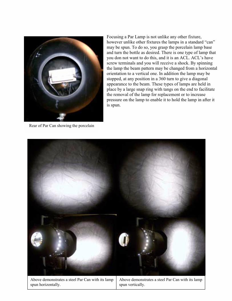
Focusing a Par Lamp is not unlike any other fixture, however unlike other fixtures the lamps in a standard can may be spun. To do so, you grasp the porcelain lamp base and turn the bottle as desired. There is one type of lamp that you don not want to do this, and it is an ACL. ACLs have screw terminals and you will receive a shock. By spinning the lamp the beam pattern may be changed from a horizontal orientation to a vertical one. In addition the lamp may be stopped, at any position in a 360 turn to give a diagonal appearance to the beam. These types of lamps are held in place by a large snap ring with tangs on the end to facilitate the removal of the lamp for replacement or to increase pressure on the lamp to enable it to hold the lamp in after it is spun.
Rear of Par Can showing the porcelain
Above demonstrates a steel Par Can with its lampspun horizontally.
Above demonstrates a steel Par Can with its lamp spun vertically.
37
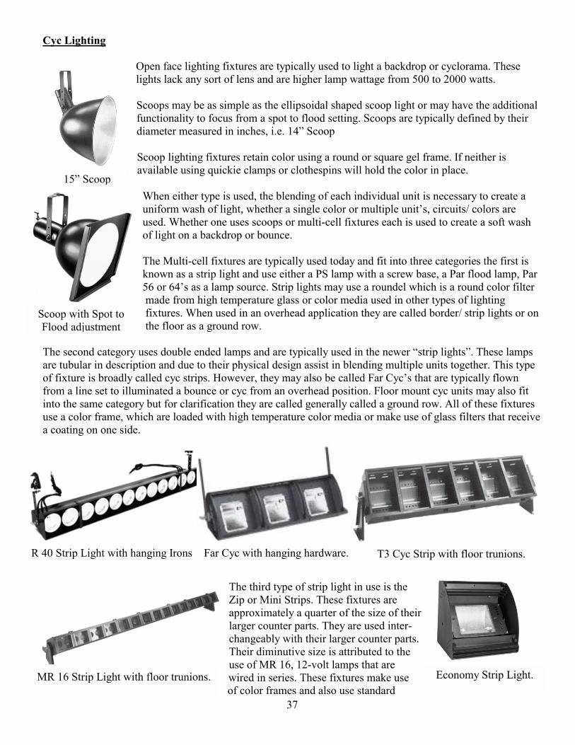
15 Scoop
R 40 Strip Light with hanging Irons Far Cyc with hanging hardware. T3 Cyc Strip with floor trunions.
MR 16 Strip Light with floor trunions. Economy Strip Light.
Scoop with Spot to Flood adjustment
Cyc Lighting
Open face lighting fixtures are typically used to light a backdrop or cyclorama. These lights lack any sort of lens and are higher lamp wattage from 500 to 2000 watts. Scoops may be as simple as the ellipsoidal shaped scoop light or may have the additional functionality to focus from a spot to flood setting. Scoops are typically defined by their diameter measured in inches, i.e. 14 Scoop Scoop lighting fixtures retain color using a round or square gel frame. If neither is available using quickie clamps or clothespins will hold the color in place. When either type is used, the blending of each individual unit is necessary to create a uniform wash of light, whether a single color or multiple units, circuits/ colors are used. Whether one uses scoops or multi-cell fixtures each is used to create a soft wash of light on a backdrop or bounce. The Multi-cell fixtures are typically used today and fit into three categories the first is known as a strip light and use either a PS lamp with a screw base, a Par flood lamp, Par 56 or 64s as a lamp source. Strip lights may use a roundel which is a round color filter made from high temperature glass or color media used in other types of lighting fixtures. When used in an overhead application they are called border/ strip lights or on the floor as a ground row.
The second category uses double ended lamps and are typically used in the newer strip lights. These lamps are tubular in description and due to their physical design assist in blending multiple units together. This type of fixture is broadly called cyc strips. However, they may also be called Far Cycs that are typically flown from a line set to illuminated a bounce or cyc from an overhead position. Floor mount cyc units may also fit into the same category but for clarification they are called generally called a ground row. All of these fixtures use a color frame, which are loaded with high temperature color media or make use of glass filters that receive a coating on one side.
The third type of strip light in use is the Zip or Mini Strips. These fixtures are approximately a quarter of the size of their larger counter parts. They are used inter-changeably with their larger counter parts. Their diminutive size is attributed to the use of MR 16, 12-volt lamps that are wired in series. These fixtures make use of color frames and also use standard

38
Mini Strips used as down stage footlights Economy Strips used as a Ground Row UPS
Economy Striplights barrel bolted together to from a five-unit strip. Note the letter G that indicates it is the seventh unit from SL and the fist space between the units
Basic Cross Section of Far Cyc
color media or glass filters for color longevity may be inserted into one of the two color slots. Usually, the first slot, closest to the lamp will contain a heat shield. The second slot will have the color media inserted.
In addition to the previous striplight types, a variant exists. These strip lights are the economy Strip Lights by Altman. The distinctive feature of these is the ability to use them, singularly or barrel bolted together to form a
traditional multi-color/ circuit strip light. These fixtures use a lightweight color frame that is bent into an arc and fitted over the lamp, as seen in the Ground Row photo. As you can see in the Far Cyc Cross section, the units contain an asymmetrical reflector. The units have specific orientations when they are hung as and overhead cyc wash and as a ground row. When they are hung from a line set, the shortest leg of the reflector will be hung closest to the top of the Cyc/ drop or bounce. If they are used as a ground row, the shortest leg of the reflector will be closest to the ground. The reasoning for this is the maximum amount of light will be projected onto the background. When using any type of Strip light or Far Cyc type unit special
attention needs to be paid to circuiting these types of units in order
39
Mazda Open Face Lights c1926
Twin Flood Light c1926
Stick-Up Mini 10 or Mini King Runt Broad Light
Audience Blinder Audience Blinder or Eight Lights
not to exceed the load capacity of the dimmers they are patched into. Typical dimmers are 2.4K each; one of these units can be up to 2000 watts per cell, a cell being one color. So the ability to twofer them are limited to two maximum units when each lamp is 1000 watts. When strip lights are used to light a cyc or backdrop, these units are hung spanning the width of the stage. Each unit has a specific color in each cell. Each one of these cells are then paired up through a combination of load patching with twofers and control patching to form a controllable color wash on the backdrop or Cyc. When using these fixtures vigilance is necessary in checking for color that has been punched out when hanging the fixtures, due to the large size gel some of these units use. In addition, light leaks in some types of Cyc units maybe problematic. To correct this problem, Black Tac or Gaffers tape is used to form a seal around the gell frame and the gell holder.
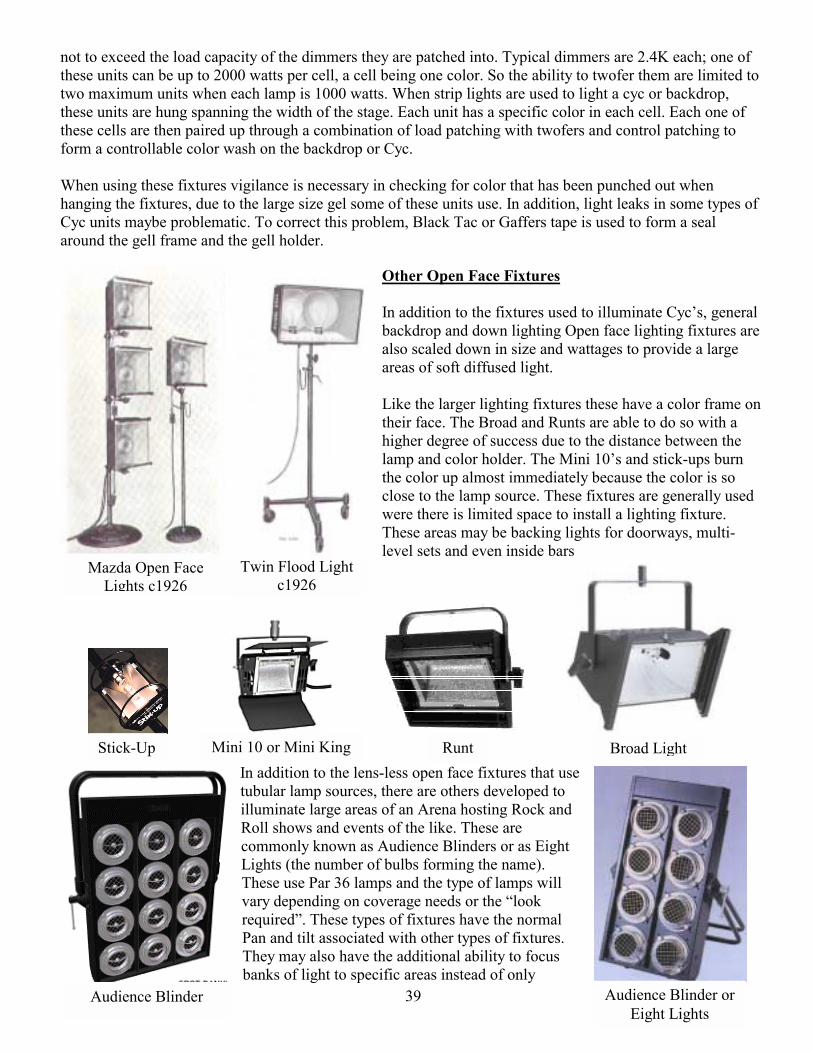
Other Open Face Fixtures In addition to the fixtures used to illuminate Cycs, general backdrop and down lighting Open face lighting fixtures are also scaled down in size and wattages to provide a large areas of soft diffused light. Like the larger lighting fixtures these have a color frame on their face. The Broad and Runts are able to do so with a higher degree of success due to the distance between the lamp and color holder. The Mini 10s and stick-ups burn the color up almost immediately because the color is so close to the lamp source. These fixtures are generally used were there is limited space to install a lighting fixture. These areas may be backing lights for doorways, multi-level sets and even inside bars
In addition to the lens-less open face fixtures that use tubular lamp sources, there are others developed to illuminate large areas of an Arena hosting Rock and Roll shows and events of the like. These are commonly known as Audience Blinders or as Eight Lights (the number of bulbs forming the name). These use Par 36 lamps and the type of lamps will vary depending on coverage needs or the look required. These types of fixtures have the normal Pan and tilt associated with other types of fixtures. They may also have the additional ability to focus banks of light to specific areas instead of only
40
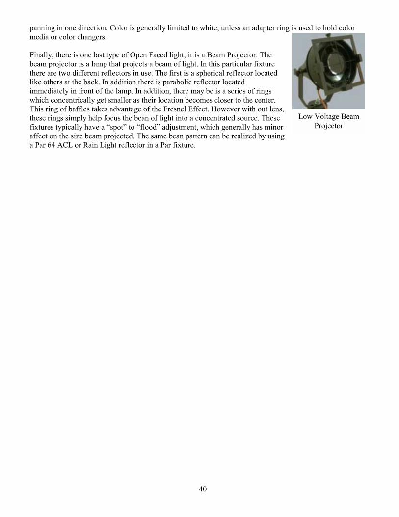
Low Voltage Beam Projector
panning in one direction. Color is generally limited to white, unless an adapter ring is used to hold color media or color changers. Finally, there is one last type of Open Faced light; it is a Beam Projector. The beam projector is a lamp that projects a beam of light. In this particular fixture there are two different reflectors in use. The first is a spherical reflector located like others at the back. In addition there is parabolic reflector located immediately in front of the lamp. In addition, there may be is a series of rings which concentrically get smaller as their location becomes closer to the center. This ring of baffles takes advantage of the Fresnel Effect. However with out lens, these rings simply help focus the bean of light into a concentrated source. These fixtures typically have a spot to flood adjustment, which generally has minor affect on the size beam projected. The same bean pattern can be realized by using a Par 64 ACL or Rain Light reflector in a Par fixture.
41
The need to remotely change color has been around for the last 50 years. Early color changers where made to employ a small number of colors and used the then standard Gels. As in previous years the need to remotely scroll through a series color still exits. Wybron electronics was one of the first to perfect a method to remotely change colors using the DMX protocol. Most color changers employ a system of two rollers that are pushed or pulled through their range of colors. Each color is tapped together using high temperature clear tape to create a scroll. These are then loaded into each unit, and depending on the model a tensioner built into one-roller holds the gel taut as it moves through the colors. The other roller is connected to a motor, to drive the gel around the rollers. These units are plugged into each other in daisy chain fashion. The starting point for these units is always a power supply. These power supplies, take line voltage and convert 110 vac into a 24-vdc voltage, to supply various voltages to the electronic components. In addition to the low voltage DC, they also pass the DMX signal to each unit. The power supplies typically have DMX in and out and additional outputs to distribute low voltage DC and DMX through a single four-pin cable that is daisy chained between units.
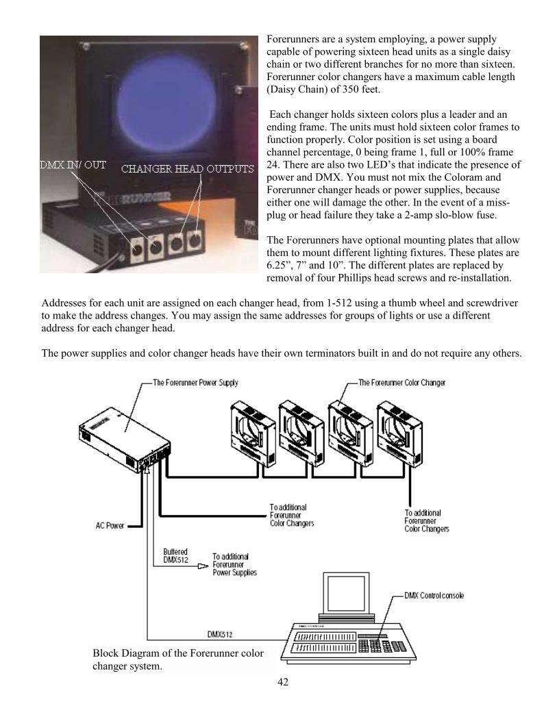
42
Block Diagram of the Forerunner color changer system.
Forerunners are a system employing, a power supply capable of powering sixteen head units as a single daisy chain or two different branches for no more than sixteen. Forerunner color changers have a maximum cable length (Daisy Chain) of 350 feet. Each changer holds sixteen colors plus a leader and an ending frame. The units must hold sixteen color frames to function properly. Color position is set using a board channel percentage, 0 being frame 1, full or 100% frame 24. There are also two LEDs that indicate the presence of power and DMX. You must not mix the Coloram and Forerunner changer heads or power supplies, because either one will damage the other. In the event of a miss-plug or head failure they take a 2-amp slo-blow fuse. The Forerunners have optional mounting plates that allow them to mount different lighting fixtures. These plates are 6.25, 7 and 10. The different plates are replaced by removal of four Phillips head screws and re-installation.
Addresses for each unit are assigned on each changer head, from 1-512 using a thumb wheel and screwdriver to make the address changes. You may assign the same addresses for groups of lights or use a different address for each changer head. The power supplies and color changer heads have their own terminators built in and do not require any others.
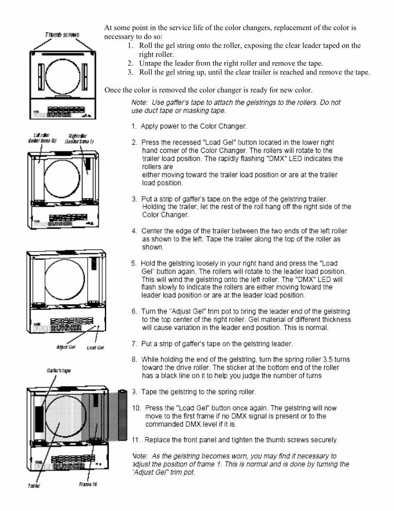
43
At some point in the service life of the color changers, replacement of the color is necessary to do so:
1. Roll the gel string onto the roller, exposing the clear leader taped on the right roller.
2. Untape the leader from the right roller and remove the tape. 3. Roll the gel string up, until the clear trailer is reached and remove the tape.
Once the color is removed the color changer is ready for new color.
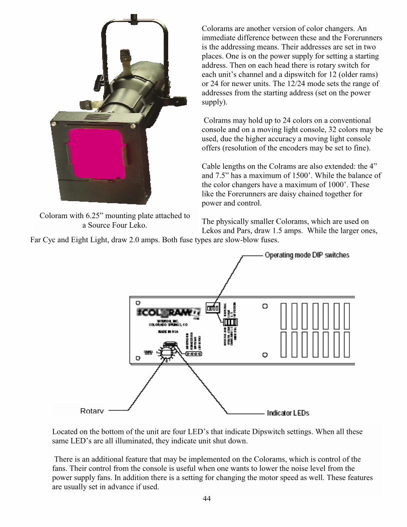
44
Located on the bottom of the unit are four LEDs that indicate Dipswitch settings. When all these same LEDs are all illuminated, they indicate unit shut down. There is an additional feature that may be implemented on the Colorams, which is control of the fans. Their control from the console is useful when one wants to lower the noise level from the power supply fans. In addition there is a setting for changing the motor speed as well. These features are usually set in advance if used.
Colorams are another version of color changers. An immediate difference between these and the Forerunners is the addressing means. Their addresses are set in two places. One is on the power supply for setting a starting address. Then on each head there is rotary switch for each units channel and a dipswitch for 12 (older rams) or 24 for newer units. The 12/24 mode sets the range of addresses from the starting address (set on the power supply). Colrams may hold up to 24 colors on a conventional console and on a moving light console, 32 colors may be used, due the higher accuracy a moving light console offers (resolution of the encoders may be set to fine). Cable lengths on the Colrams are also extended: the 4 and 7.5 has a maximum of 1500. While the balance of the color changers have a maximum of 1000. These like the Forerunners are daisy chained together for power and control. The physically smaller Colorams, which are used on Lekos and Pars, draw 1.5 amps. While the larger ones,
Far Cyc and Eight Light, draw 2.0 amps. Both fuse types are slow-blow fuses.
Coloram with 6.25 mounting plate attached to a Source Four Leko.
Rotary
45
When a show has been shop prepped, most all of the settings and addresss will have been preset. Typically the user settable dipswitches and addresses are recorded on a label stuck to the unit. This enables a spare to be substituted easily without looking for paper work. However, on a show site you may be required do addressing and dipswitch setting when assisting swapping units for show maintenance. Addressing Scrollers, is one of the most frequent tasks you will be asked to perform on these units The necessary instructions to address the Power Supplies are included, for a complete copy of these; consult printed or downloaded instructions from Wybron. One item to be aware of is the ease in getting lost in the menu commands to do the setup and start addressing. Following are excerpts to cover the two tasks. The three different Coloram power supplies require the following fuses: 24 way 7 amp, 12 way 4 amp, and 6 way 2 amp. All three use slow-blow fuses.
Front View of Power Supply Rear View Showing DMX and Coloram outputs
46
Setup continued:
47
Commands Continued:
Changing the color scrolls used in the Colorams is another necessary skill to have. Unlike the Forerunners that use a set length color scroll, which determines its position within the scroll. Colorams use a tag system to define the length of the color scroll, without them the color changer will roll to the very end.
To the left is a picture of a color scroll, which shows the foil tags and location of the first and last color frames.
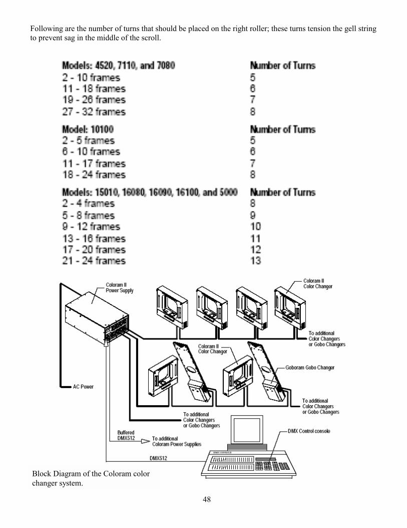
48
Following are the number of turns that should be placed on the right roller; these turns tension the gell string to prevent sag in the middle of the scroll.
Block Diagram of the Coloram color changer system.
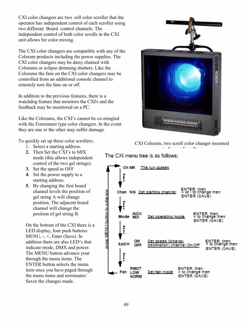
49
CXI Coloram, two scroll color changer mounted to Source Four Par.
CXI color changers are two roll color scroller that the operator has independent control of each scroller using two different Board control channels. The independent control of both color scrolls in the CXI unit allows for color mixing. The CXI color changers are compatible with any of the Coloram products including the power supplies. The CXI color changers may be daisy chained with Colorams or eclipse dimming shutters. Like the Colorams the fans on the CXI color changers may be controlled from an additional console channel to remotely turn the fans on or off. In addition to the previous features, there is a watchdog feature that monitors the CXI's and the feedback may be monitored on a PC. Like the Colorams, the CXIs cannot be co-mingled with the Forerunner type color changers. In the event they are one or the other may suffer damage. To quickly set up these color scrollers:
1. Select a starting address. 2. Then Set the CXIs to MIX
mode (this allows independent control of the two gel strings).
3. Set the speed to OFF 4. Set the power supply to a
starting address. 5. By changing the first board
channel levels the position of gel string A will change position. The adjacent board channel will change the position of gel string B.
On the bottom of the CXI there is a LED display, four push buttons: MENU, -, +, Enter (Save). In addition there are also LEDs that indicate mode, DMX and power. The MENU button advance your through the menu items. The ENTER button selects the menu item once you have paged through the menu items and terminates/ Saves the changes made.
50
One thing to keep in mind when setting the address is the formula to determine the address of the unit. The following formula is used to determine the address for each unit:
DMX= CXI Channel+ power supply starting channel 1 Or stated differently:
CXI channel = DMX channel- power supply starting channel +1
Example: DMX control channel 10 is desired. CXI channel set to 4 Power supply starting channel 7+ 11-1=10
1.Press the menu Button. 2.Press the enter Button. 3.Use the + or buttons to find the address number. 4. Press enter again to save the address.
The CXI color changers have two different modes of operation; the first is indexing which positions both strings of gel, and the second channel of the CXI controls the speed at which the strings move. The other mode of operation is mixing mode, when this mode is used the first DMX channel of the CXI controls the first gel string. The Second DMX channel controls the other scroll. The third possible channel will control the speed of both gel strings; the speed needs to be enabled through the menu commands on the bottom of the CXI unit. When the CXI are in Mix Mode the Console channel sets the position by the board percentage, if it is set at a half percentage, the scroller will be set at a half frame. There are some restrictions that are imposed upon the CXIs due to the Coloram power supplies. Using the 24 Way Power Supply gives you the address range of 1 to 48. The 12 way supply 1 to 24 and the 6 way 1 to 12. Each of the power supplies receives and retransmits gel string position in similar blocks of information as the address ranges. The 24 way receives data as a block of 48 which is also the maximum number of CXI addresses that are available. Like the Colorams, the CXIs have a maximum cable length to observe or Head-Feet length. Head-Feet length is defined as all cable from the Power Supply to last CXI color changer. Model 4560 4 inch CXI 750 head-feet max. Model 7160 7.5 inch CXI 750 head-feet max. Model 1011 10 inch CXI 500 head-feet max The maximum number of CXI color changers that may be cabled from a Coloram power supply is as follows: 24 Way Power Supply supplies 600 watts may power 12 CXIs 12 Way Power Supply supplies 300 watts may power 6 CXIs 6 Way Power Supply supplies 150 watts may power 3 CXIs The general specifications of the CXIs: Power requirement are 3 Amp Slow-Blo fuses They are able to hold a gel string with 23 frames. The LED indicates: Index mode Yellow LED DMX signal Green LED Power present Red LED
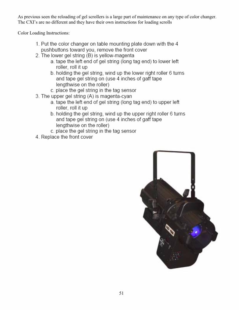
51
As previous seen the reloading of gel scrollers is a large part of maintenance on any type of color changer. The CXIs are no different and they have their own instructions for loading scrolls Color Loading Instructions:
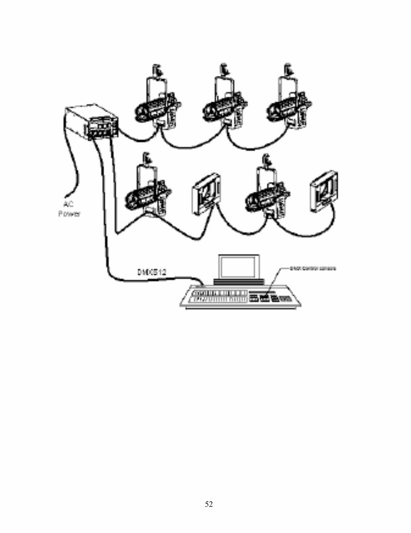
52

53
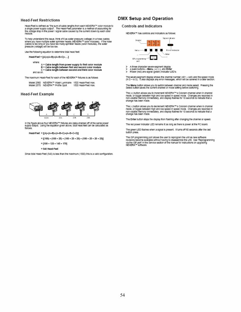
54
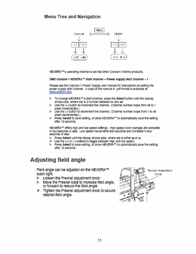
55
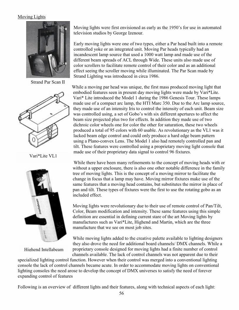
56
Strand Par Scan II
Vari*Lite VL1
Highend Intellabeam
Moving Lights
Moving lights were first envisioned as early as the 1950s for use in automated television studios by George Izenour.
Early moving lights were one of two types, either a Par head built into a remote controlled yoke or an integrated unit. Moving Par heads typically had an incandescent lamp source that used a 1000 watt lamp and made use of the different beam spreads of ACL through Wide. These units also made use of color scrollers to facilitate remote control of their color and as an additional effect seeing the scroller moving while illuminated. The Par Scan made by Strand Lighting was introduced in circa 1986.
While a moving par head was unique, the first mass produced moving light that embodied features seen in present day moving lights were made by Vari*Lite. Vari* Lite introduced the Model 1 during the 1986 Genesis Tour. These lamps made use of a compact arc lamp, the HTI Marc 350. Due to the Arc lamp source, they made use of an intensity Iris to control the intensity of each unit. Beam size was controlled using, a set of Gobos with six different apertures to affect the beam size projected plus two for effects. In addition they made use of two dichroic color wheels one for color the other for saturation, these two wheels produced a total of 95 colors with 60 usable. As revolutionary as the VL1 was it lacked beam edge control and could only produce a hard edge beam pattern using a Plano-convex Lens. The Model 1 also had remotely controlled pan and tilt. These features were controlled using a proprietary moving light console that made use of their proprietary data signal to control 96 fixtures. While there have been many refinements to the concept of moving heads with or without a upper enclosure, there is also one other notable difference in the family tree of moving lights. This is the concept of a moving mirror to facilitate the change in focus that a lamp may have. Moving mirror fixtures make use of the same features that a moving head contains, but substitutes the mirror in place of pan and tilt. These types of fixtures were the first to use the rotating gobo as an included effect. Moving lights were revolutionary due to their use of remote control of Pan/Tilt, Color, Beam modification and intensity. These same features using this simple definition are essential in defining current stare of the art Moving lights by manufactures such as Vari*Lite, Highend and Martin, which are the three manufacture that we see on most job sites. While moving lights added to the creative palette available to lighting designers they also drove the need for additional board channels/ DMX channels. While a proprietary console designed for moving lights had a finite number of control channels available. The lack of control channels was not apparent due to their
specialized lighting control function. However when their control was merged into a conventional lighting console the lack of control channels became acute. In order to accommodate moving lights on conventional lighting consoles the need arose to develop the concept of DMX universes to satisfy the need of forever expanding control of features Following is an overview of different lights and their features, along with technical aspects of each light:
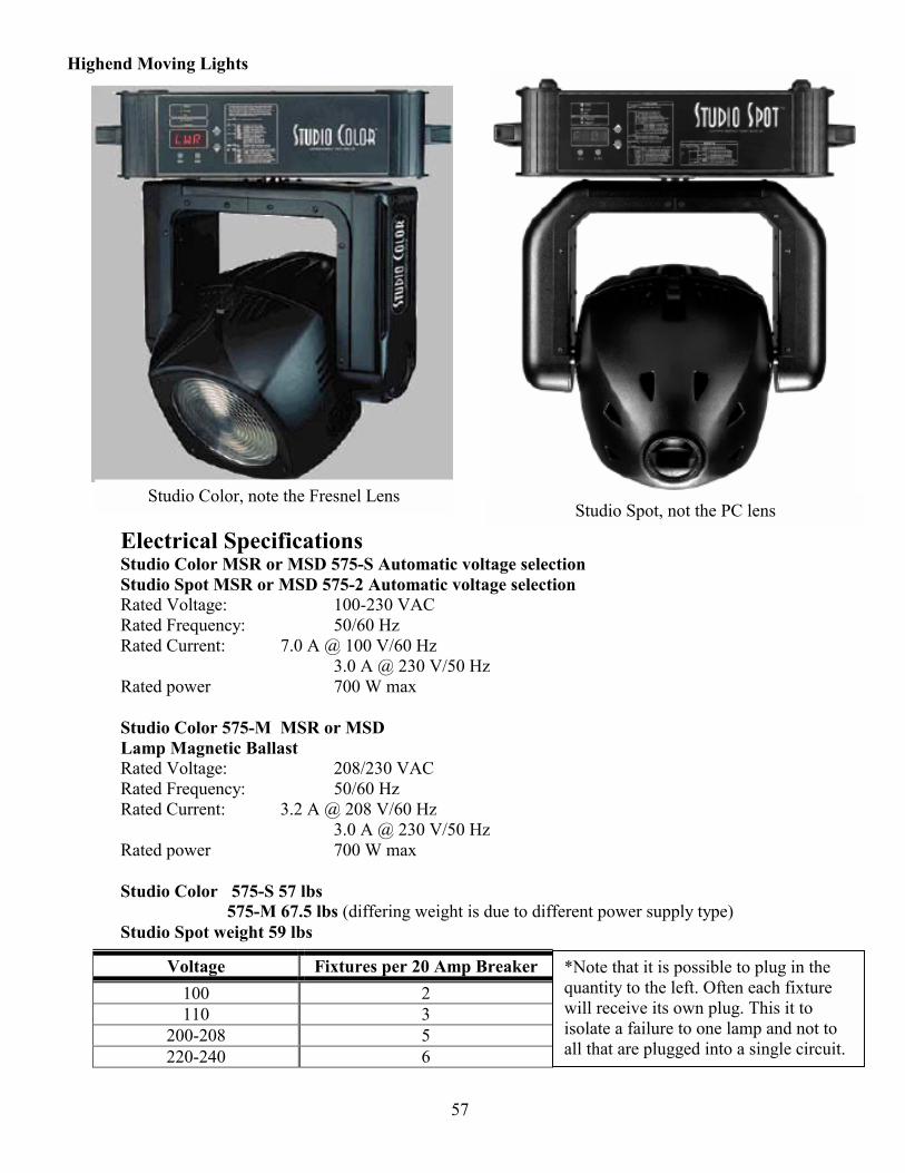
57
Studio Color, note the Fresnel Lens Studio Spot, not the PC lens
Highend Moving Lights
Electrical Specifications Studio Color MSR or MSD 575-S Automatic voltage selection Studio Spot MSR or MSD 575-2 Automatic voltage selection Rated Voltage: 100-230 VAC Rated Frequency: 50/60 Hz Rated Current: 7.0 A @ 100 V/60 Hz 3.0 A @ 230 V/50 Hz Rated power 700 W max Studio Color 575-M MSR or MSD Lamp Magnetic Ballast Rated Voltage: 208/230 VAC Rated Frequency: 50/60 Hz Rated Current: 3.2 A @ 208 V/60 Hz 3.0 A @ 230 V/50 Hz Rated power 700 W max Studio Color 575-S 57 lbs 575-M 67.5 lbs (differing weight is due to different power supply type) Studio Spot weight 59 lbs
Voltage Fixtures per 20 Amp Breaker 100 2 110 3
200-208 5 220-240 6
*Note that it is possible to plug in the quantity to the left. Often each fixture will receive its own plug. This it to isolate a failure to one lamp and not to all that are plugged into a single circuit.
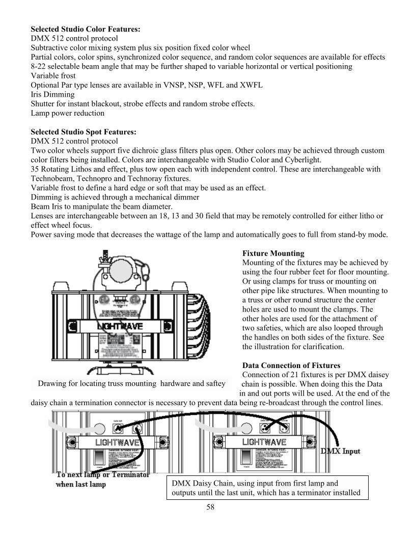
58
Drawing for locating truss mounting hardware and saftey
Selected Studio Color Features: DMX 512 control protocol Subtractive color mixing system plus six position fixed color wheel Partial colors, color spins, synchronized color sequence, and random color sequences are available for effects 8-22 selectable beam angle that may be further shaped to variable horizontal or vertical positioning Variable frost Optional Par type lenses are available in VNSP, NSP, WFL and XWFL Iris Dimming Shutter for instant blackout, strobe effects and random strobe effects. Lamp power reduction Selected Studio Spot Features: DMX 512 control protocol Two color wheels support five dichroic glass filters plus open. Other colors may be achieved through custom color filters being installed. Colors are interchangeable with Studio Color and Cyberlight. 35 Rotating Lithos and effect, plus tow open each with independent control. These are interchangeable with Technobeam, Technopro and Technoray fixtures. Variable frost to define a hard edge or soft that may be used as an effect. Dimming is achieved through a mechanical dimmer Beam Iris to manipulate the beam diameter. Lenses are interchangeable between an 18, 13 and 30 field that may be remotely controlled for either litho or effect wheel focus. Power saving mode that decreases the wattage of the lamp and automatically goes to full from stand-by mode.
Fixture Mounting Mounting of the fixtures may be achieved by using the four rubber feet for floor mounting. Or using clamps for truss or mounting on other pipe like structures. When mounting to a truss or other round structure the center holes are used to mount the clamps. The other holes are used for the attachment of two safeties, which are also looped through the handles on both sides of the fixture. See the illustration for clarification. Data Connection of Fixtures Connection of 21 fixtures is per DMX daisey chain is possible. When doing this the Data
in and out ports will be used. At the end of the daisy chain a termination connector is necessary to prevent data being re-broadcast through the control lines.
DMX Daisy Chain, using input from first lamp and outputs until the last unit, which has a terminator installed
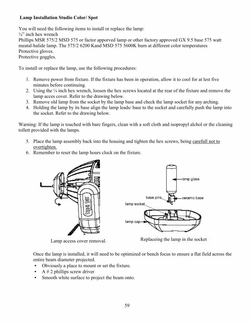
59
Replaceing the lamp in the socket Lamp access cover removal.
Lamp Installation Studio Color/ Spot You will need the following items to install or replace the lamp: ¼ inch hex wrench Phillips MSR 575/2 MSD 575 or factor apporved lamp or other factory approved GX 9.5 base 575 watt meatal-halide lamp. The 575/2 6200 Kand MSD 575 5600K burn at different color temperatures Protective gloves. Protective goggles. To install or replace the lamp, use the following procedures:
1. Remove power from fixture. If the fixture has been in operation, allow it to cool for at lest five minutes before continuing.
2. Using the ¼ inch hex wrench, loosen the hex screws located at the rear of the fixture and remove the lamp acces cover. Refer to the drawing below.
3. Remove old lamp from the socket by the lamp base and check the lamp socket for any arching. 4. Holding the lamp by its base align the lamp leads/ base to the socket and carefully push the lamp into
the socket. Refer to the drawing below. Warning: If the lamp is touched with bare fingers, clean with a soft cloth and isopropyl alchol or the cleaning tollett provided with the lamps.
5. Place the lamp assembly back into the housing and tighten the hex screws, being carefull not to overtighten.
6. Remember to reset the lamp hours clock on the fixture.
Once the lamp is installed, it will need to be optimized or bench focus to ensure a flat field across the entire beam diameter projected. • Obviously a place to mount or set the fixture. • A # 2 phillips screw driver • Smooth white surface to project the beam onto.
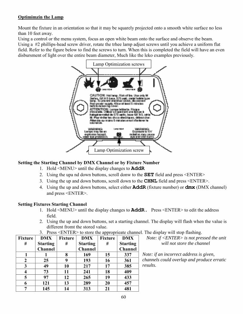
60
Optimimzin the Lamp Mount the fixture in an orientation so that it may be squarely projected onto a smooth white surface no less than 10 feet away. Using a control or the menu system, focus an open white beam onto the surface and observe the beam. Using a #2 phillips-head screw driver, rotate the trhee lamp adjust screws until you achieve a uniform flat field. Refer to the figure below to find the screws to turn. When this is completed the field will have an even disbursment of light over the entire beam diameter, Much like the leko examples previously.
Setting the Starting Channel by DMX Channel or by Fixture Number
1. Hold <MENU> until the display changes to AddR 2. Using the upa nd down buttons, scroll donw to the SET field and press <ENTER> 3. Using the up and down buttons, scroll down to the CHNL field and press <ENTER>. 4. Using the up and down buttons, select either AddR (fixture number) or dmx (DMX channel)
and press <ENTER>. Setting Fixtures Starting Channel
1. Hold <MENU> until the display changes to AddR. Press <ENTER> to edit the address field.
2. Using the up and down buttons, set a starting channel. The display will flash when the value is different fromt the stored value.
3. Press <ENTER> to store the approprieate channel. The display will stop flashing. Note: if <ENTER> is not pressed the unit
will not store the channel
Note: if an incorrect address is given, channels could overlap and produce erratic results.
Fixture #
DMX Starting Channel
Fixture #
DMX Starting Channel
Fixture#
DMX StartingChannel
1 1 8 169 15 337 2 25 9 193 16 361 3 49 10 217 17 385 4 73 11 241 18 409 5 97 12 265 19 433 6 121 13 289 20 457 7 145 14 313 21 481
Lamp Optimization screw
Lamp Optimization screws
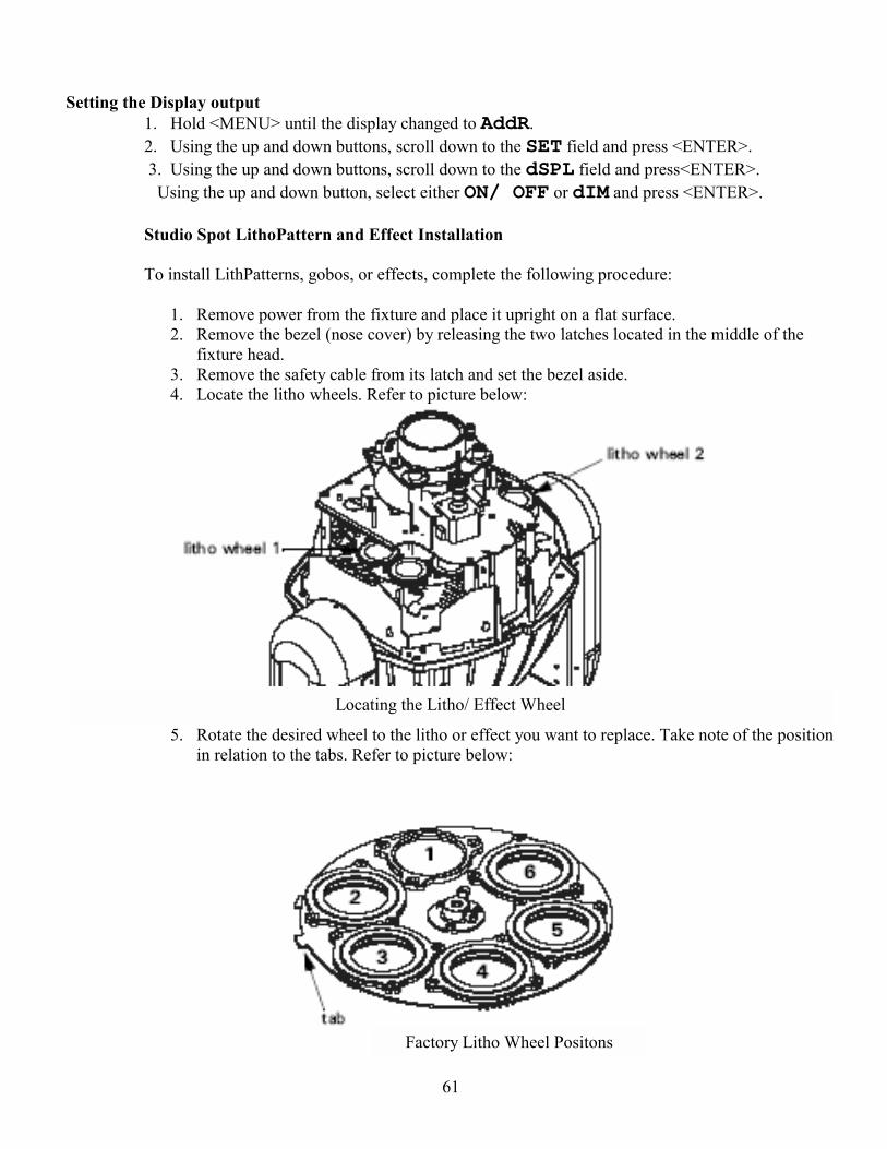
61
Factory Litho Wheel Positons
Locating the Litho/ Effect Wheel
Setting the Display output
1. Hold <MENU> until the display changed to AddR. 2. Using the up and down buttons, scroll down to the SET field and press <ENTER>. 3. Using the up and down buttons, scroll down to the dSPL field and press<ENTER>. Using the up and down button, select either ON/ OFF or dIM and press <ENTER>. Studio Spot LithoPattern and Effect Installation To install LithPatterns, gobos, or effects, complete the following procedure:
1. Remove power from the fixture and place it upright on a flat surface. 2. Remove the bezel (nose cover) by releasing the two latches located in the middle of the
fixture head. 3. Remove the safety cable from its latch and set the bezel aside. 4. Locate the litho wheels. Refer to picture below:
5. Rotate the desired wheel to the litho or effect you want to replace. Take note of the position in relation to the tabs. Refer to picture below:
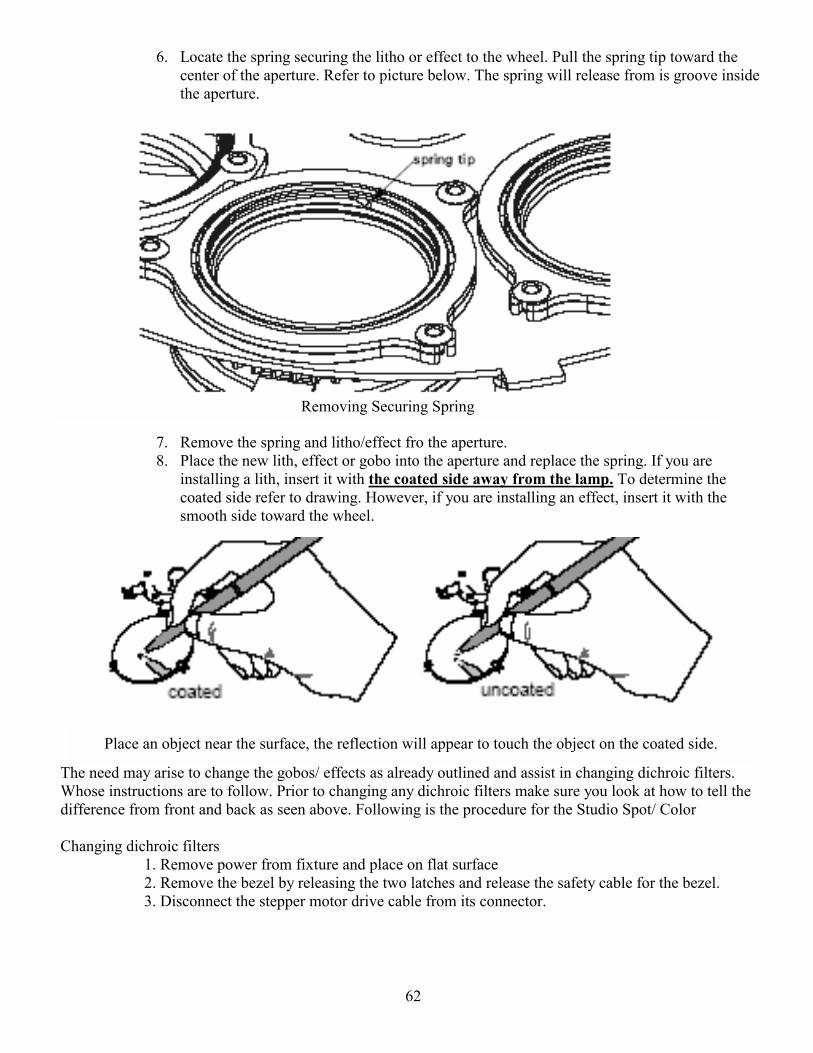
62
Removing Securing Spring
Place an object near the surface, the reflection will appear to touch the object on the coated side.
6. Locate the spring securing the litho or effect to the wheel. Pull the spring tip toward the center of the aperture. Refer to picture below. The spring will release from is groove inside the aperture.
7. Remove the spring and litho/effect fro the aperture. 8. Place the new lith, effect or gobo into the aperture and replace the spring. If you are
installing a lith, insert it with the coated side away from the lamp. To determine the coated side refer to drawing. However, if you are installing an effect, insert it with the smooth side toward the wheel.
The need may arise to change the gobos/ effects as already outlined and assist in changing dichroic filters. Whose instructions are to follow. Prior to changing any dichroic filters make sure you look at how to tell the difference from front and back as seen above. Following is the procedure for the Studio Spot/ Color Changing dichroic filters 1. Remove power from fixture and place on flat surface
2. Remove the bezel by releasing the two latches and release the safety cable for the bezel. 3. Disconnect the stepper motor drive cable from its connector.
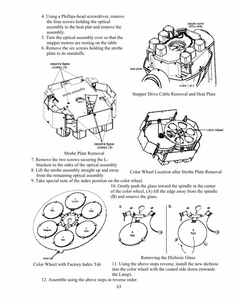
63
Strobe Plate Removal
Stepper Drive Cable Removal and Heat Plate
Color Wheel Location after Strobe Plate Removal
Color Wheel with Factory Index Tab
4. Using a Phillips-head screwdriver, remove the four screws holding the optical assembly to the heat plat and remove the assembly.
5. Turn the optical assembly over so that the stepper motors are resting on the table
6. Remove the six screws holding the strobe plate to its standoffs.
7. Remove the two screws securing the L-brackets to the sides of the optical assembly
8. Lift the strobe assembly straight up and away from the remaining optical assembly
9. Take special note of the index position on the color wheel. 10. Gently push the glass toward the spindle in the center of the color wheel, (A) lift the edge away from the spindle (B) and remove the glass.
11. Using the above steps reverse, install the new dichroic into the color wheel with the coated side down (towards the Lamp).
12. Assemble using the above steps in reverse order.
Removing the Dichroic Glass
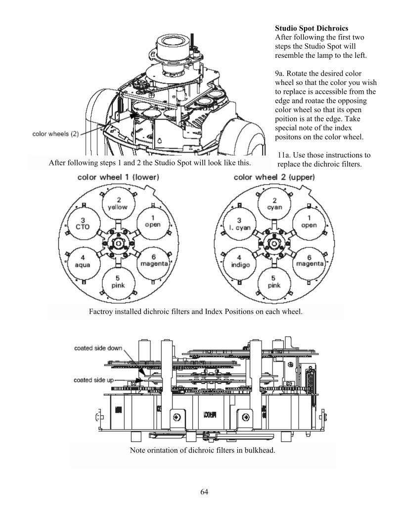
64
After following steps 1 and 2 the Studio Spot will look like this.
Factroy installed dichroic filters and Index Positions on each wheel.
Studio Spot Dichroics After following the first two steps the Studio Spot will resemble the lamp to the left. 9a. Rotate the desired color wheel so that the color you wish to replace is accessible from the edge and roatae the opposing color wheel so that its open poition is at the edge. Take special note of the index positons on the color wheel. 11a. Use those instructions to replace the dichroic filters.
Note orintation of dichroic filters in bulkhead.
65
Often times moving lights will have self-Tests that may performed on themselves. Following are the steps necessary to access these on both the Studio Color/ Spot. Self-Tests For a comprehensive list of test refer to either manuel. The following are the button strokes to access these on either type of light. The Studio Spot has an additional two to access these, so complete all five when working on this light, Studio Color has one less, skip step 3. To begin the tests:
1. Hold <Menu> until the display changes to AddR. 2. Using the up and down buttons, scroll to the TEST field and press <ENTER>. 3. Using the up and down buttons, scroll to the SELF field and press <ENTER >. 4. Using the up and down buttons, scroll to the desired test and press < ENTER >. The fixture will
perform the desired tests. To exit the sets in progress, press to invert or swap the pan and tilt functions. This depends on the hanging position or if the fixture is located on the stage. As a floor light you may need to invert the Pan and Tilt. By doing this the Pan and Tilt encoders will only need to turned in one direction instead of remembering the fixtures orientation and its affect on the fixture. Or when they are mounted sideways the pan and tilt may be swapped. Following are the excerpts on how to do this. Inverting Pan and Tilt When fixtures are mounted on the floor (upside down), the pan and tilt can be inverted.
1. Hold < Menu > until the display changed to AddR. 2. Using the up and down buttons, scroll to the SET filed and press <ENTER >. 3. Using the up and down buttons, scroll to the T for tilts or P for pan field and press
<ENTER >. 4. Using the up and down buttons, select either ON or OFF and press <ENTER >.
Swapping Pan and Tilt When fixtures are mounted sideways, swap the pan and tilt functions. 1. Hold < Menu > until the display changed to AddR. 2. Using the up and down buttons, scroll to the SET filed and press <ENTER >.
3. Using the up and down buttons, scroll to the SWAP filed and press the <ENTER >. 4. Using the up and down buttons select either ON or OFF and press <ENTER >.
66
Excerpts from Studio Spot Menu system: Studio Spot:
67
68
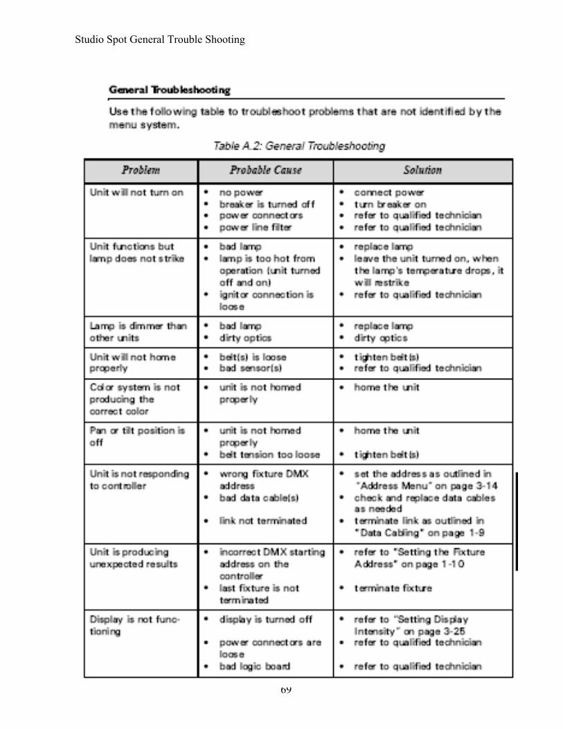
69
Studio Spot General Trouble Shooting

70
Studio Wash Menu System:
71

72
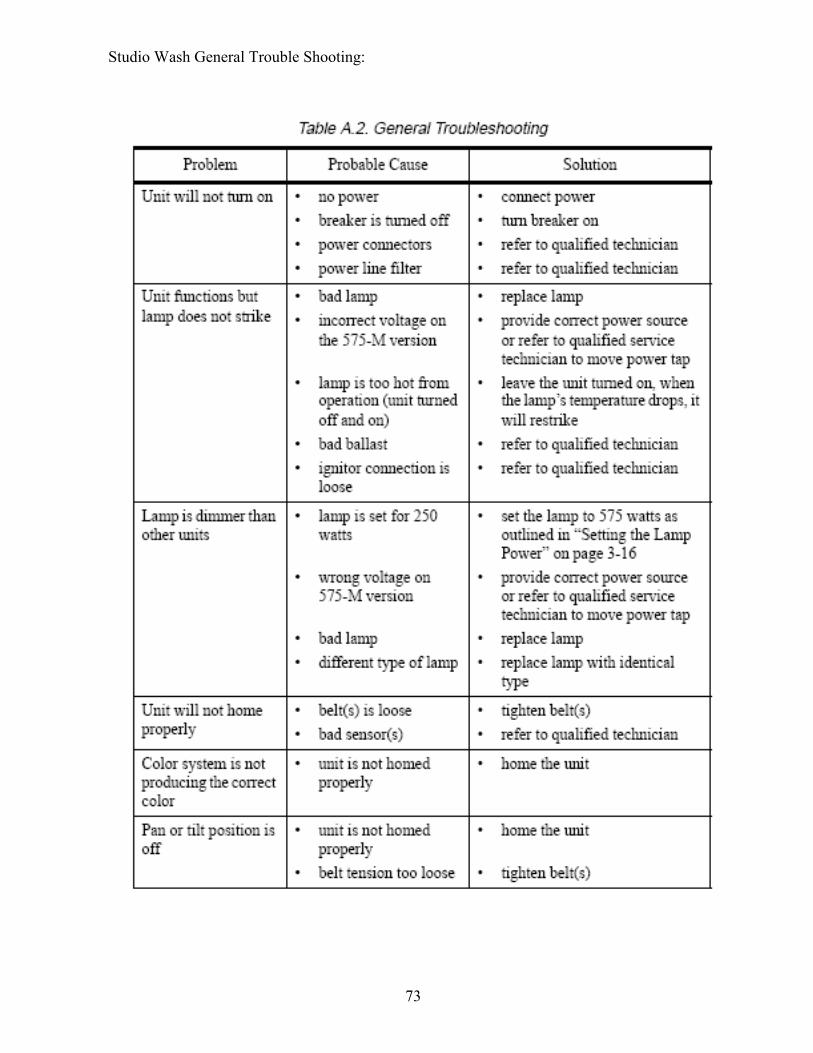
73
Studio Wash General Trouble Shooting:
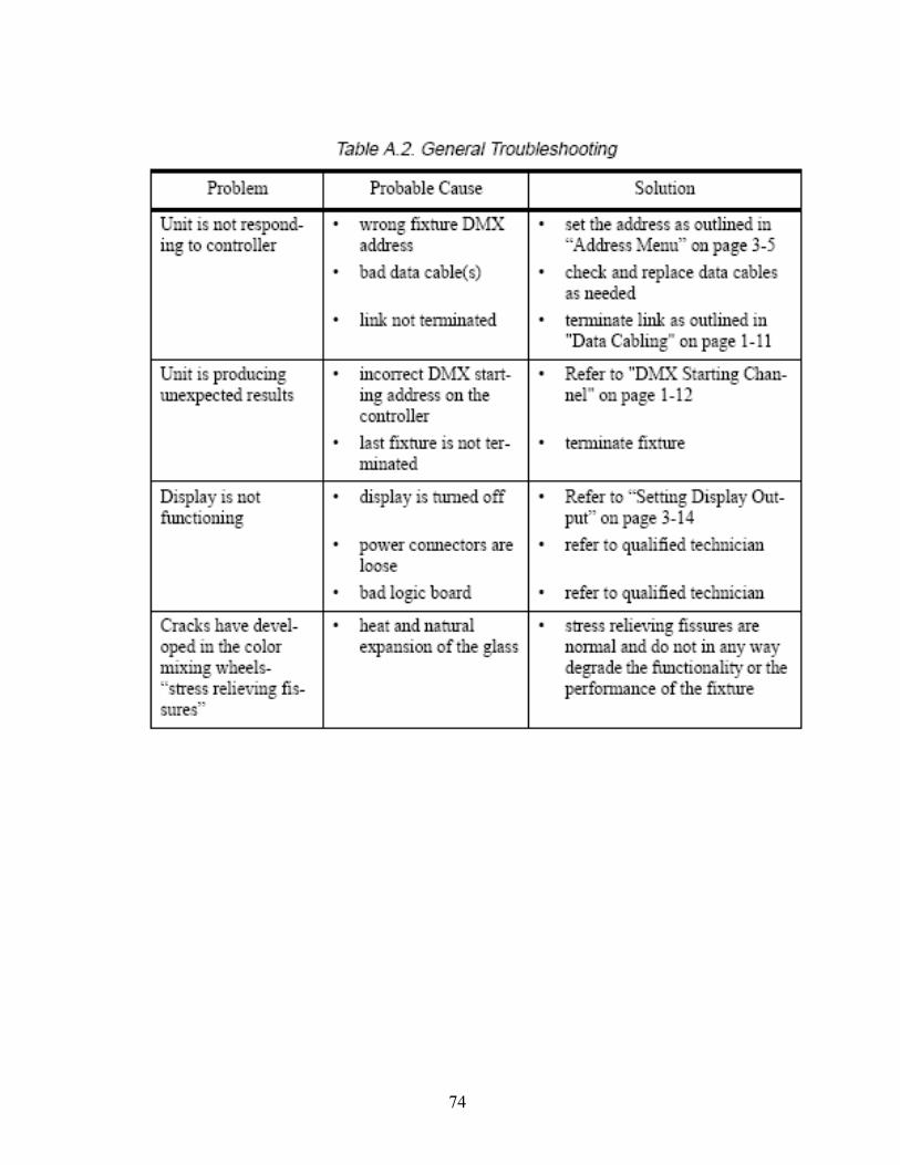
74
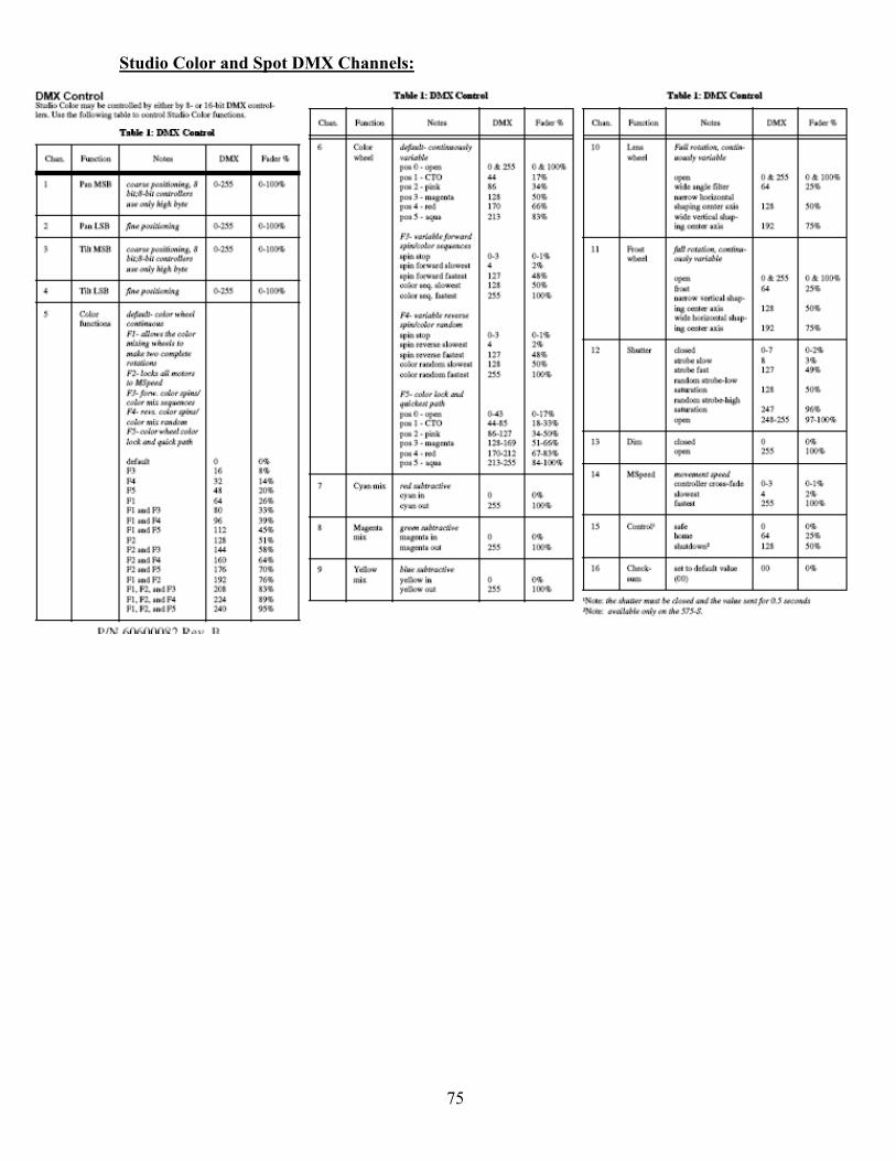
75
Studio Color and Spot DMX Channels:
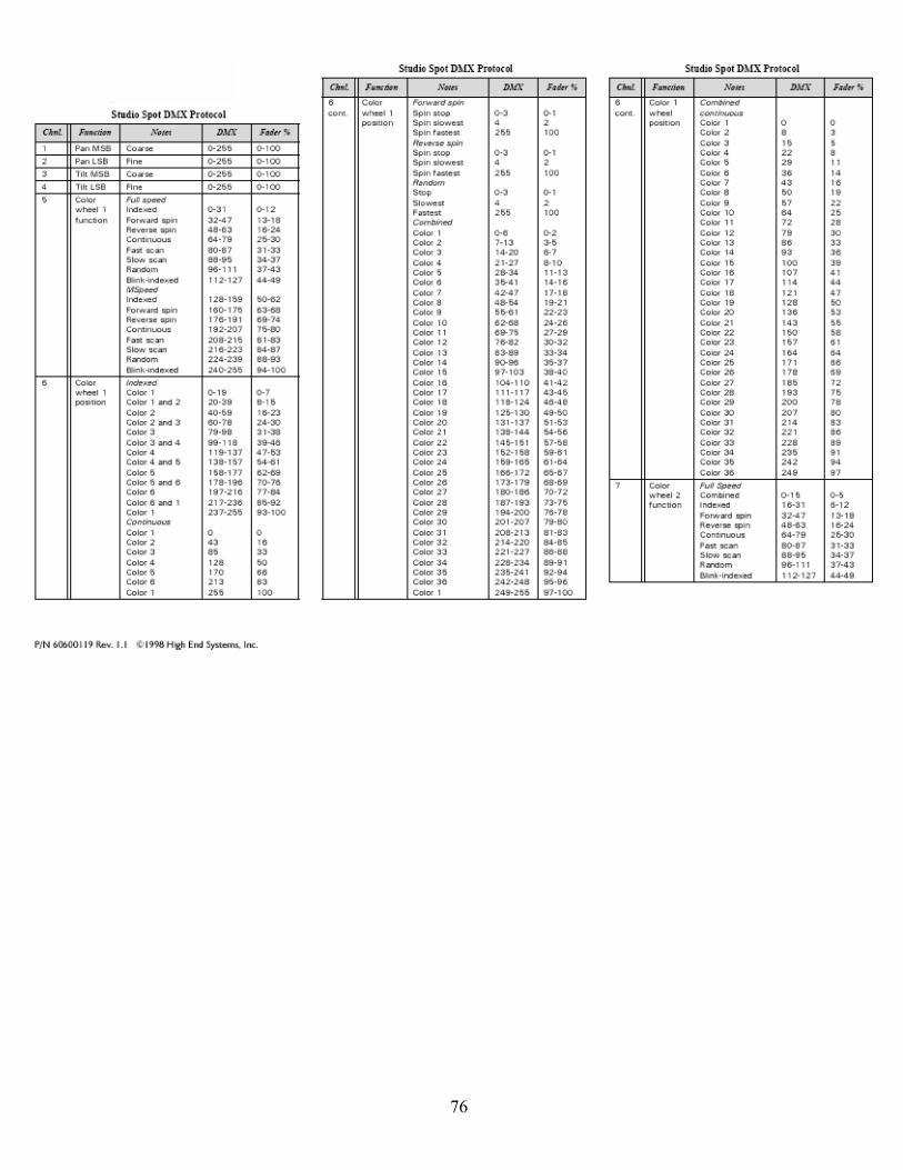
76

77

78

79
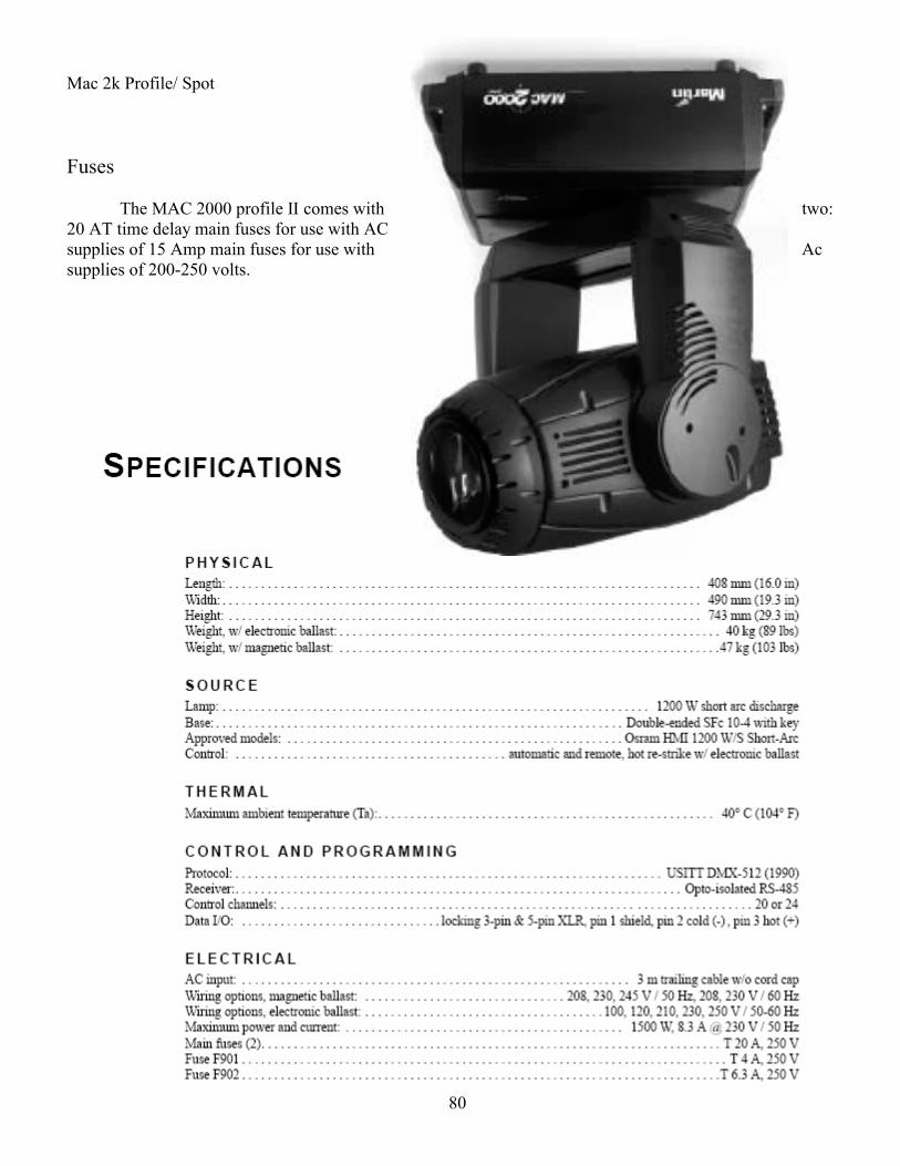
80
Mac 2k Profile/ Spot Fuses The MAC 2000 profile II comes with two: 20 AT time delay main fuses for use with AC supplies of 15 Amp main fuses for use with Ac supplies of 200-250 volts.
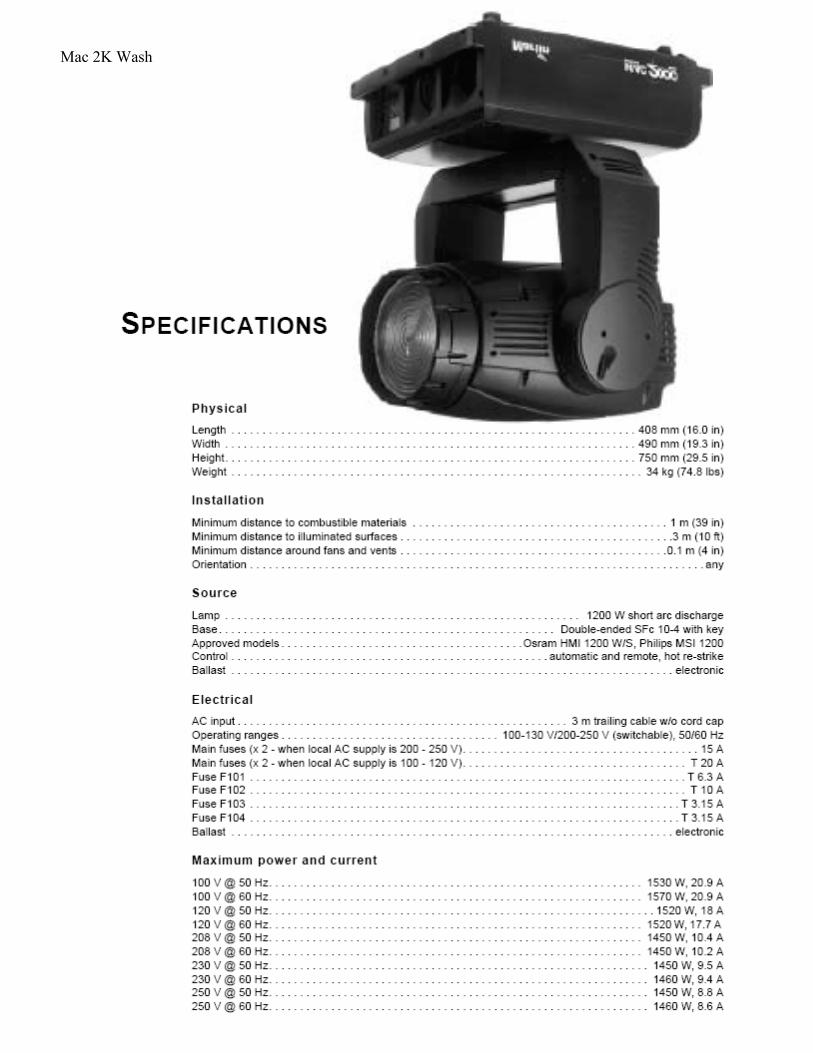
81
Mac 2K Wash
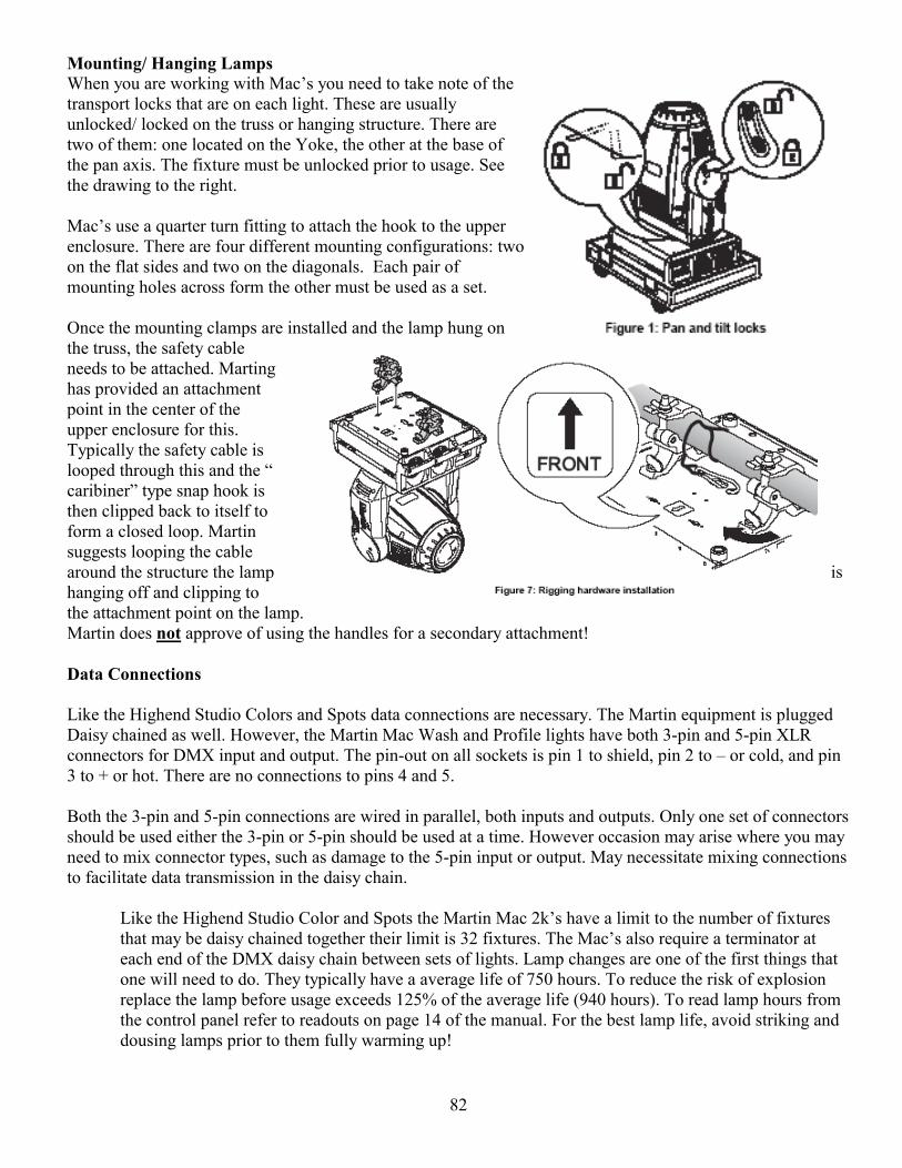
82
Mounting/ Hanging Lamps When you are working with Macs you need to take note of the transport locks that are on each light. These are usually unlocked/ locked on the truss or hanging structure. There are two of them: one located on the Yoke, the other at the base of the pan axis. The fixture must be unlocked prior to usage. See the drawing to the right. Macs use a quarter turn fitting to attach the hook to the upper enclosure. There are four different mounting configurations: two on the flat sides and two on the diagonals. Each pair of mounting holes across form the other must be used as a set. Once the mounting clamps are installed and the lamp hung on the truss, the safety cable needs to be attached. Marting has provided an attachment point in the center of the upper enclosure for this. Typically the safety cable is looped through this and the caribiner type snap hook is then clipped back to itself to form a closed loop. Martin suggests looping the cable around the structure the lamp is hanging off and clipping to the attachment point on the lamp. Martin does not approve of using the handles for a secondary attachment! Data Connections Like the Highend Studio Colors and Spots data connections are necessary. The Martin equipment is plugged Daisy chained as well. However, the Martin Mac Wash and Profile lights have both 3-pin and 5-pin XLR connectors for DMX input and output. The pin-out on all sockets is pin 1 to shield, pin 2 to or cold, and pin 3 to + or hot. There are no connections to pins 4 and 5. Both the 3-pin and 5-pin connections are wired in parallel, both inputs and outputs. Only one set of connectors should be used either the 3-pin or 5-pin should be used at a time. However occasion may arise where you may need to mix connector types, such as damage to the 5-pin input or output. May necessitate mixing connections to facilitate data transmission in the daisy chain.
Like the Highend Studio Color and Spots the Martin Mac 2ks have a limit to the number of fixtures that may be daisy chained together their limit is 32 fixtures. The Macs also require a terminator at each end of the DMX daisy chain between sets of lights. Lamp changes are one of the first things that one will need to do. They typically have a average life of 750 hours. To reduce the risk of explosion replace the lamp before usage exceeds 125% of the average life (940 hours). To read lamp hours from the control panel refer to readouts on page 14 of the manual. For the best lamp life, avoid striking and dousing lamps prior to them fully warming up!
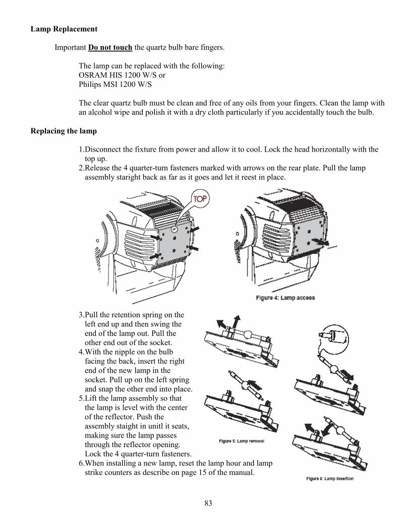
83
Lamp Replacement Important Do not touch the quartz bulb bare fingers.
The lamp can be replaced with the following: OSRAM HIS 1200 W/S or Philips MSI 1200 W/S The clear quartz bulb must be clean and free of any oils from your fingers. Clean the lamp with an alcohol wipe and polish it with a dry cloth particularly if you accidentally touch the bulb.
Replacing the lamp
1.Disconnect the fixture from power and allow it to cool. Lock the head horizontally with the
top up. 2.Release the 4 quarter-turn fasteners marked with arrows on the rear plate. Pull the lamp
assembly staright back as far as it goes and let it reest in place.
3.Pull the retention spring on the left end up and then swing the end of the lamp out. Pull the other end out of the socket.
4.With the nipple on the bulb facing the back, insert the right end of the new lamp in the socket. Pull up on the left spring and snap the other end into place.
5.Lift the lamp assembly so that the lamp is level with the center of the reflector. Push the assembly staight in unitl it seats, making sure the lamp passes through the reflector opening. Lock the 4 quarter-turn fasteners.
6.When installing a new lamp, reset the lamp hour and lamp strike counters as describe on page 15 of the manual.
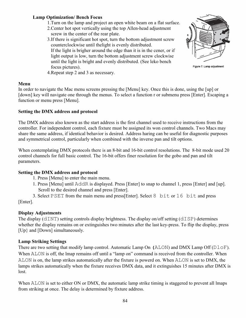
84
Lamp Optimization/ Bench Focus 1.Turn on the lamp and project an open white beam on a flat surface. 2.Center hot spot vertically using the top Allen-head adjustment
screw in the center of the rear plate. 3.If there is significant hot spot, turn the bottom adjustment screw
counterclockwise until thelight is evenly distributed. If the light is brigher around the edge than it is in the cener, or if light output is low, turn the bottom adjustment screw clockwise until the light is bright and evenly distributed. (See leko bench focus pictures).
4.Repeat step 2 and 3 as necessary. Menu In order to navigate the Mac menu screens pressing the [Menu] key. Once this is done, using the [up] or [down] key will navigate one through the menus. To select a function r or submenu press [Enter]. Escaping a function or menu press [Menu]. Setting the DMX address and protocol The DMX address also known as the start address is the first channel used to receive instructions from the controller. For independent control, each fixture must be assigned its won control channels. Two Macs may share the same address, if identical behavior is desired. Address haring can be useful for diagnostic purposes and symmetrical control, particularly when combined with the inverse pan and tilt options. When contemplating DMX protocols there is an 8-bit and 16-bit control resolutions. The 8-bit mode used 20 control channels for full basic control. The 16-bit offers finer resolution for the gobo and pan and tilt parameters. Setting the DMX address and protocol
1. Press [Menu] to enter the main menu. 1. Press [Menu] until AddR is displayed. Press [Enter] to snap to channel 1, press [Enter] and [up].
Scroll to the desired channel and press [Enter]. 3. Select PSET from the main menu and press[Enter]. Select 8 bit or 16 bit and press
[Enter].
Display Adjustments The display (dINT) setting controls display brightness. The display on/off setting (dISP) determines whether the display remains on or extinguishes two minutes after the last key-press. To flip the display, press [Up and [Down] simultaneously. Lamp Striking Settings There are two setting that modify lamp control. Automatic Lamp On (ALON) and DMX Lamp Off (DloF). When ALON is off, the lmap remains off until a lamp on command is received from the controller. When ALON is on, the lamp strikes automatically after the fixture is powerd on. When ALON is set to DMX, the lamps strikes automatically when the fixture receives DMX data, and it extinguishes 15 minutes after DMX is lost. When ALON is set to either ON or DMX, the automatic lamp strike timing is staggered to prevent all lmaps from striking at once. The delay is determined by fixture address.
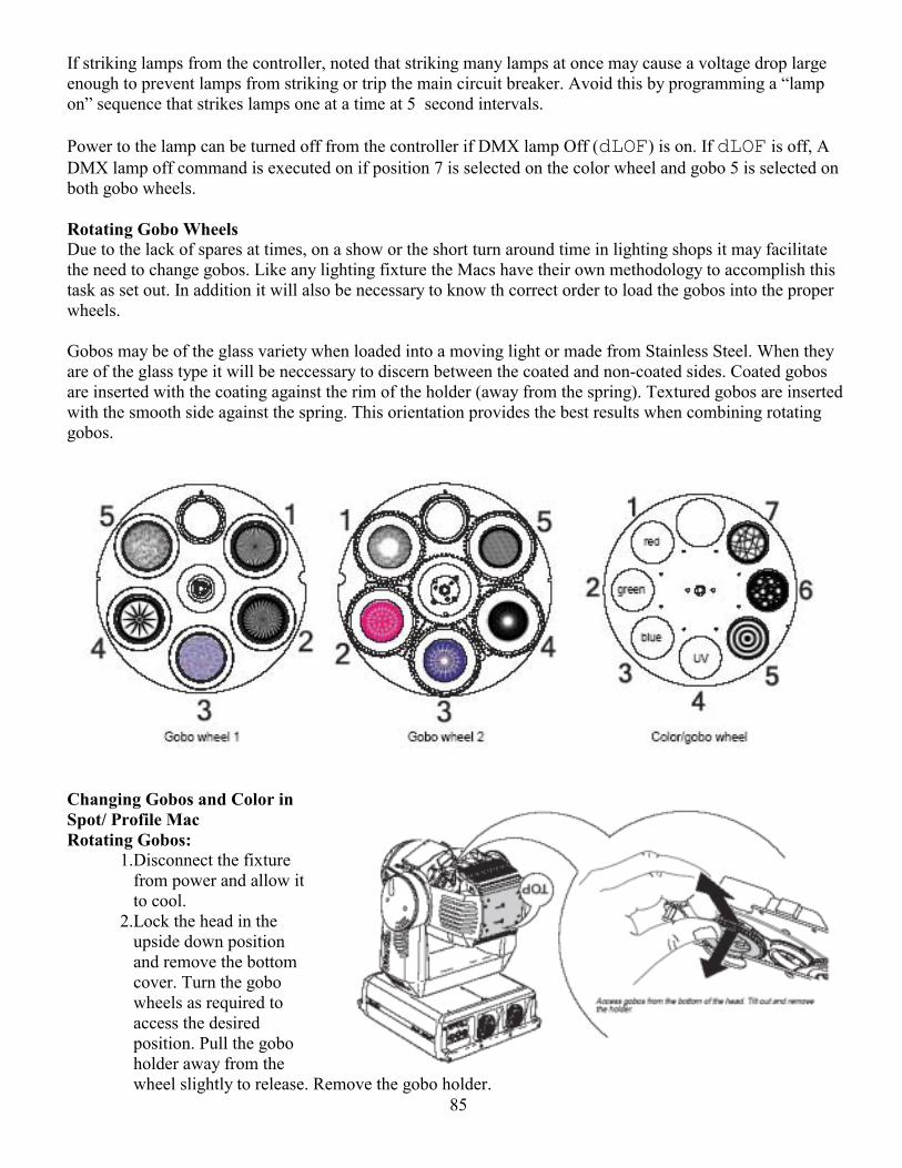
85
If striking lamps from the controller, noted that striking many lamps at once may cause a voltage drop large enough to prevent lamps from striking or trip the main circuit breaker. Avoid this by programming a lamp on sequence that strikes lamps one at a time at 5 second intervals. Power to the lamp can be turned off from the controller if DMX lamp Off (dLOF) is on. If dLOF is off, A DMX lamp off command is executed on if position 7 is selected on the color wheel and gobo 5 is selected on both gobo wheels. Rotating Gobo Wheels Due to the lack of spares at times, on a show or the short turn around time in lighting shops it may facilitate the need to change gobos. Like any lighting fixture the Macs have their own methodology to accomplish this task as set out. In addition it will also be necessary to know th correct order to load the gobos into the proper wheels. Gobos may be of the glass variety when loaded into a moving light or made from Stainless Steel. When they are of the glass type it will be neccessary to discern between the coated and non-coated sides. Coated gobos are inserted with the coating against the rim of the holder (away from the spring). Textured gobos are inserted with the smooth side against the spring. This orientation provides the best results when combining rotating gobos.
Changing Gobos and Color in Spot/ Profile Mac Rotating Gobos:
1.Disconnect the fixture from power and allow it to cool.
2.Lock the head in the upside down position and remove the bottom cover. Turn the gobo wheels as required to access the desired position. Pull the gobo holder away from the wheel slightly to release. Remove the gobo holder.
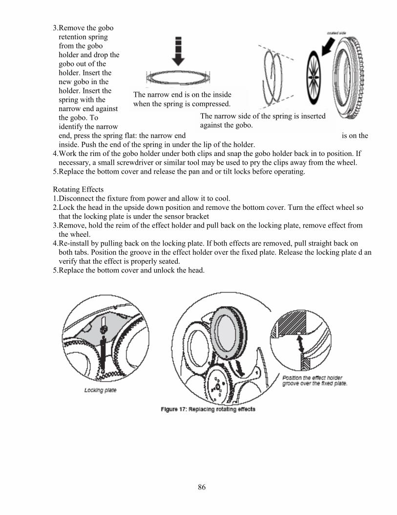
86
The narrow end is on the inside when the spring is compressed.
The narrow side of the spring is inserted against the gobo.
3.Remove the gobo retention spring from the gobo holder and drop the gobo out of the holder. Insert the new gobo in the holder. Insert the spring with the narrow end against the gobo. To identify the narrow end, press the spring flat: the narrow end is on the inside. Push the end of the spring in under the lip of the holder.
4.Work the rim of the gobo holder under both clips and snap the gobo holder back in to position. If necessary, a small screwdriver or similar tool may be used to pry the clips away from the wheel.
5.Replace the bottom cover and release the pan and or tilt locks before operating. Rotating Effects 1.Disconnect the fixture from power and allow it to cool. 2.Lock the head in the upside down position and remove the bottom cover. Turn the effect wheel so
that the locking plate is under the sensor bracket 3.Remove, hold the reim of the effect holder and pull back on the locking plate, remove effect from
the wheel. 4.Re-install by pulling back on the locking plate. If both effects are removed, pull straight back on
both tabs. Position the groove in the effect holder over the fixed plate. Release the locking plate d an verify that the effect is properly seated.
5.Replace the bottom cover and unlock the head.
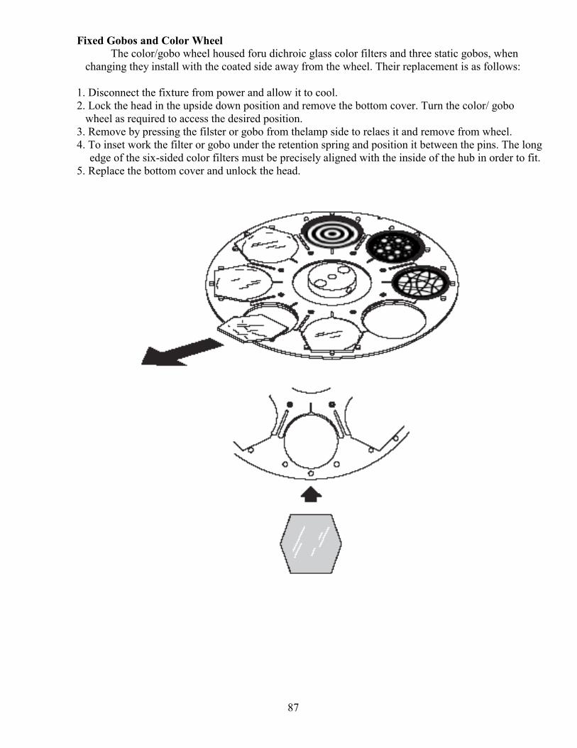
87
Fixed Gobos and Color Wheel The color/gobo wheel housed foru dichroic glass color filters and three static gobos, when
changing they install with the coated side away from the wheel. Their replacement is as follows: 1. Disconnect the fixture from power and allow it to cool. 2. Lock the head in the upside down position and remove the bottom cover. Turn the color/ gobo wheel as required to access the desired position. 3. Remove by pressing the filster or gobo from thelamp side to relaes it and remove from wheel. 4. To inset work the filter or gobo under the retention spring and position it between the pins. The long
edge of the six-sided color filters must be precisely aligned with the inside of the hub in order to fit. 5. Replace the bottom cover and unlock the head.
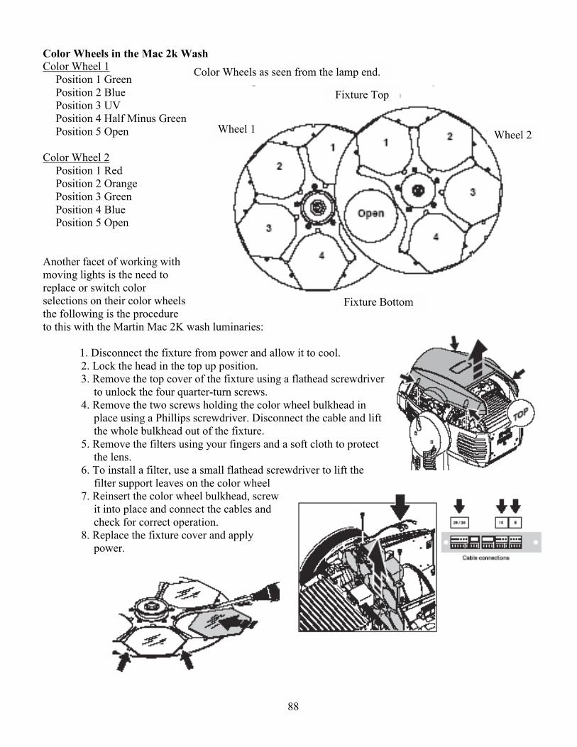
88
Color Wheels as seen from the lamp end.
Fixture Bottom
Wheel 1 Wheel 2
Fixture Top
Color Wheels in the Mac 2k Wash Color Wheel 1
Position 1 Green Position 2 Blue Position 3 UV Position 4 Half Minus Green Position 5 Open
Color Wheel 2
Position 1 Red Position 2 Orange Position 3 Green Position 4 Blue Position 5 Open
Another facet of working with moving lights is the need to replace or switch color selections on their color wheels the following is the procedure to this with the Martin Mac 2K wash luminaries:
1. Disconnect the fixture from power and allow it to cool. 2. Lock the head in the top up position. 3. Remove the top cover of the fixture using a flathead screwdriver
to unlock the four quarter-turn screws. 4. Remove the two screws holding the color wheel bulkhead in
place using a Phillips screwdriver. Disconnect the cable and lift the whole bulkhead out of the fixture.
5. Remove the filters using your fingers and a soft cloth to protect the lens.
6. To install a filter, use a small flathead screwdriver to lift the filter support leaves on the color wheel
7. Reinsert the color wheel bulkhead, screw it into place and connect the cables and check for correct operation.
8. Replace the fixture cover and apply power.
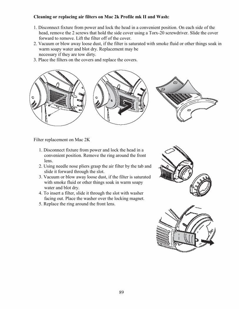
89
Cleaning or replacing air filters on Mac 2k Profile mk II and Wash: 1. Disconnect fixture from power and lock the head in a convenient position. On each side of the
head, remove the 2 screws that hold the side cover using a Torx-20 screwdriver. Slide the cover forward to remove. Lift the filter off of the cover.
2. Vacuum or blow away loose dust, if the filter is saturated with smoke fluid or other things soak in warm soapy water and blot dry. Replacement may be necessary if they are tow dirty.
3. Place the filters on the covers and replace the covers.
Filter replacement on Mac 2K
1. Disconnect fixture from power and lock the head in a convenient position. Remove the ring around the front lens.
2. Using needle nose pliers grasp the air filter by the tab and slide it forward through the slot.
3. Vacuum or blow away loose dust, if the filter is saturated with smoke fluid or other things soak in warm soapy water and blot dry.
4. To insert a filter, slide it through the slot with washer facing out. Place the washer over the locking magnet.
5. Replace the ring around the front lens.
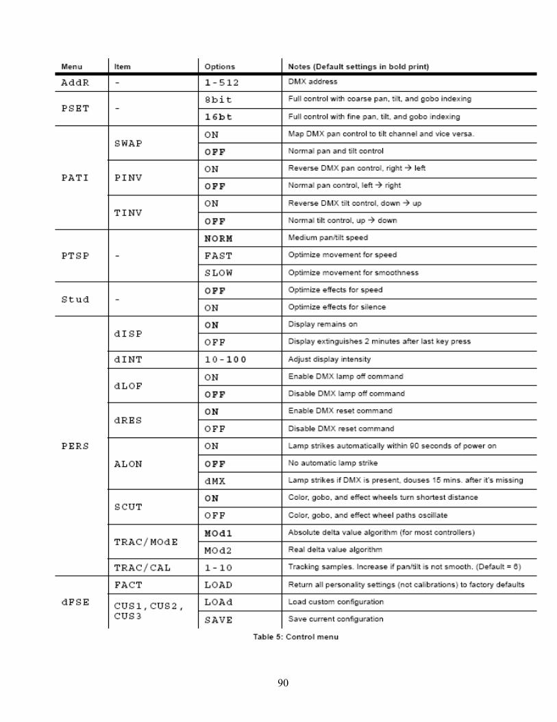
90
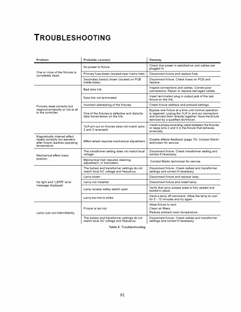
91
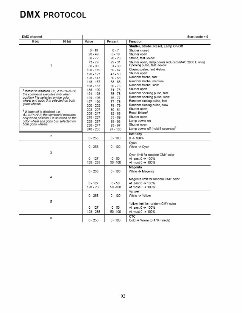
92
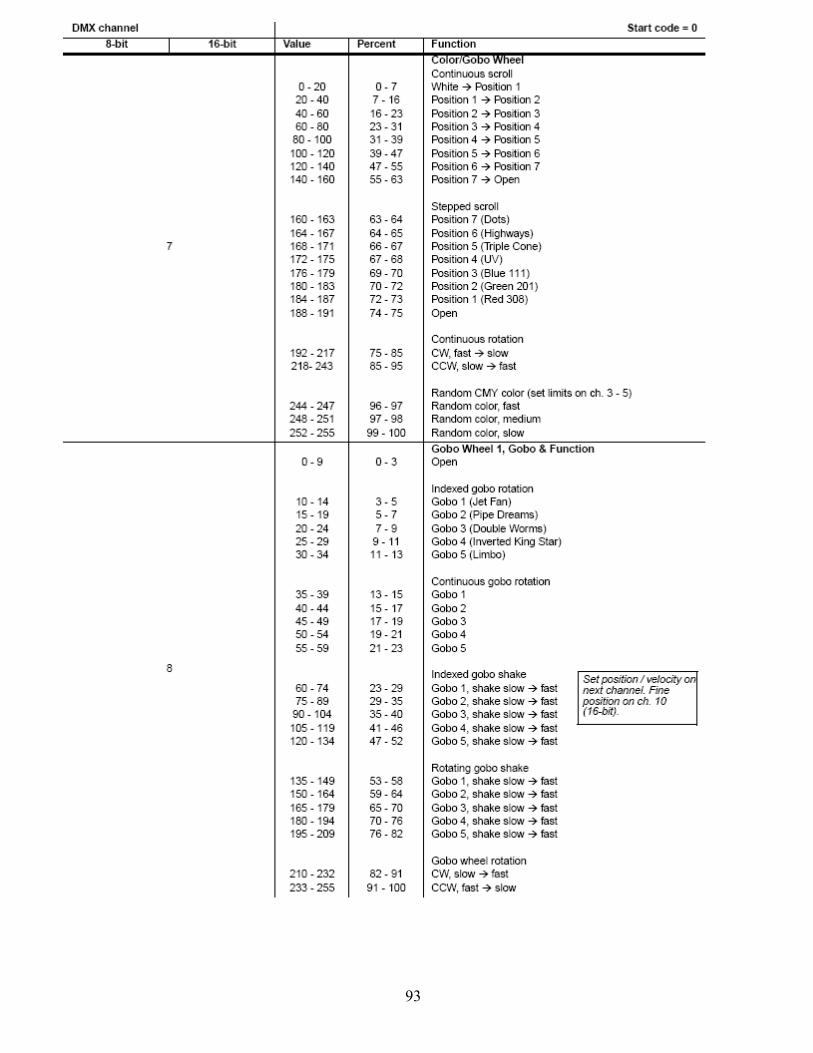
93
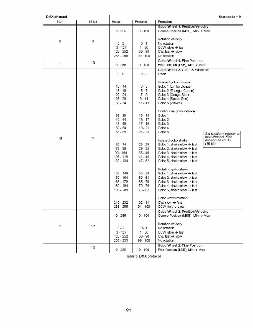
94
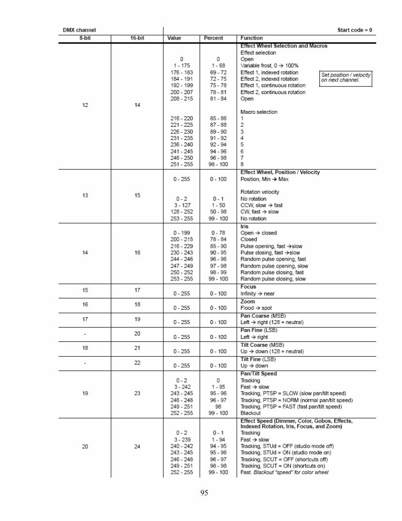
95

96
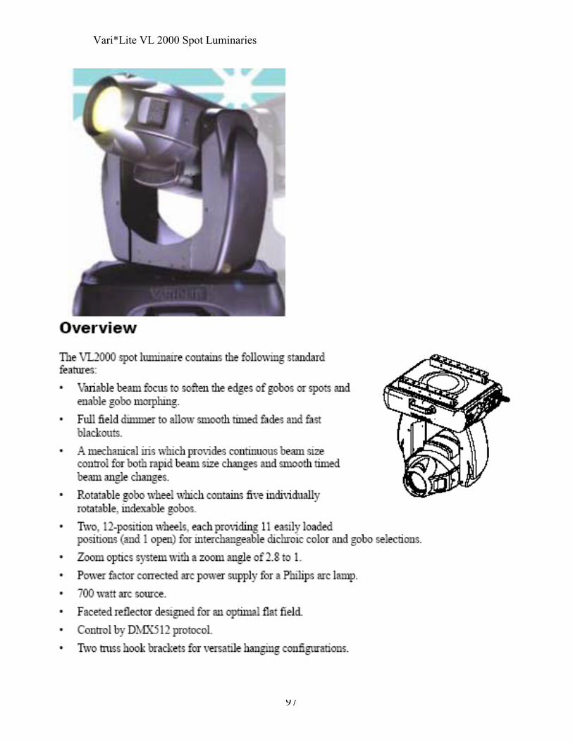
97
Vari*Lite VL 2000 Spot Luminaries

98
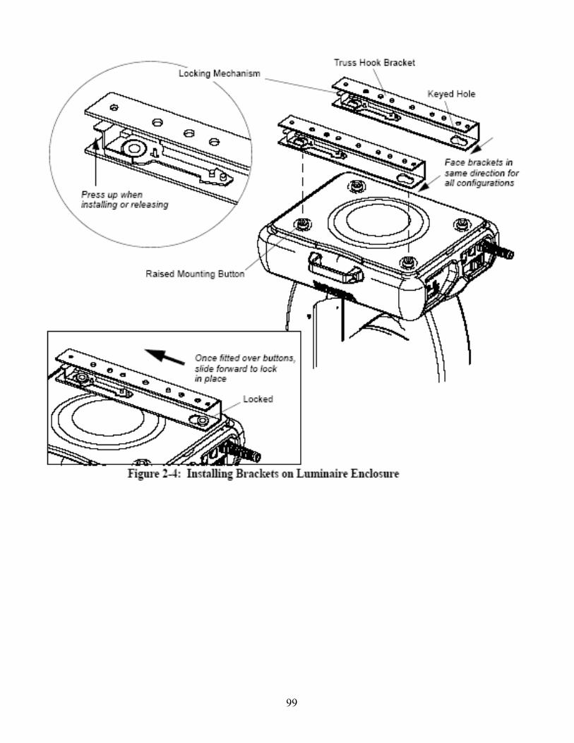
99
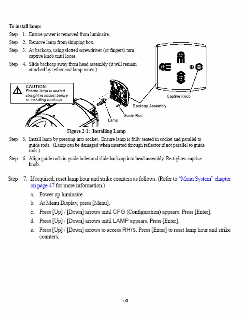
100
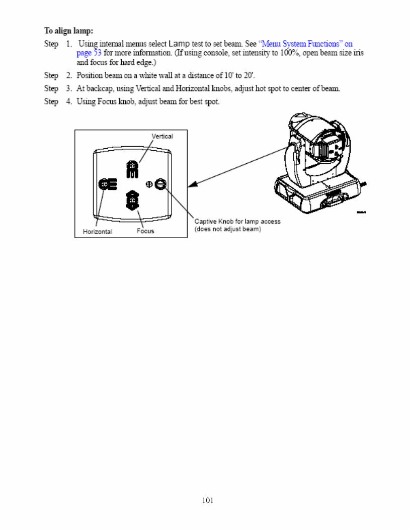
101

102
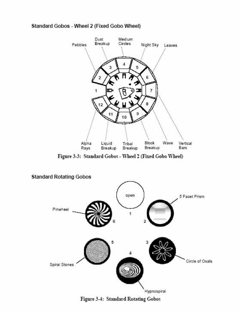
103
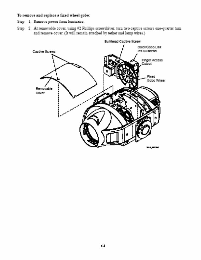
104
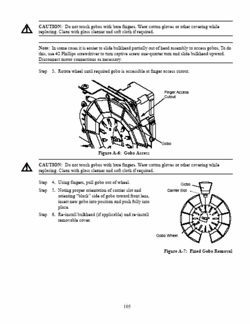
105
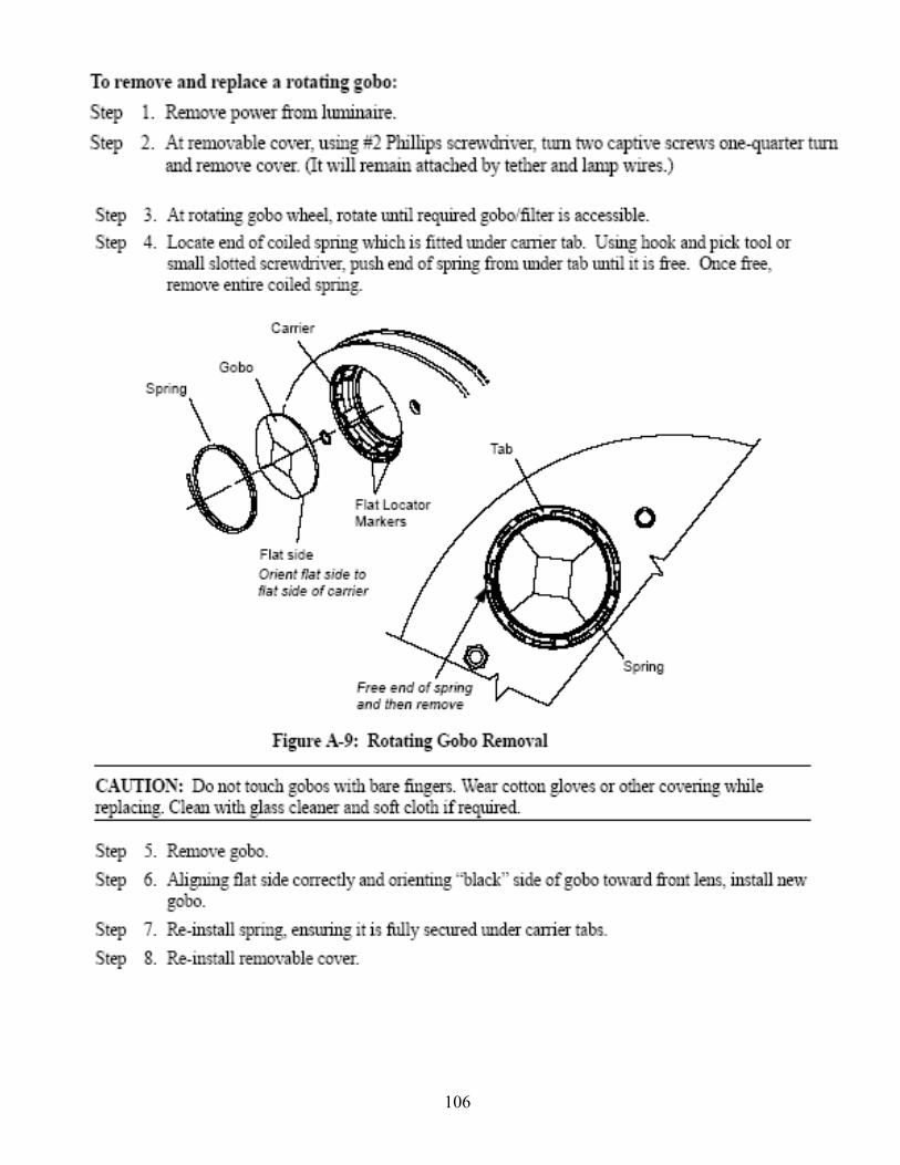
106
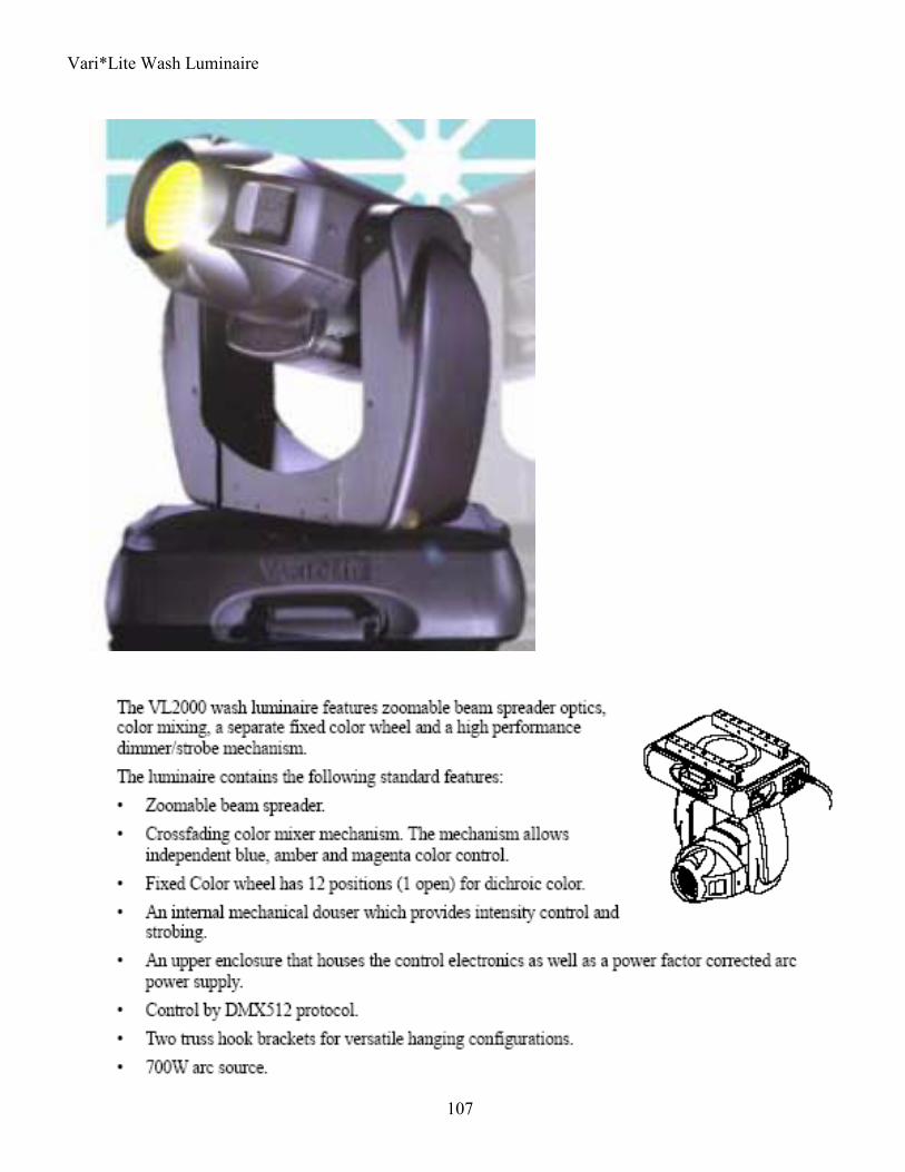
107
Vari*Lite Wash Luminaire
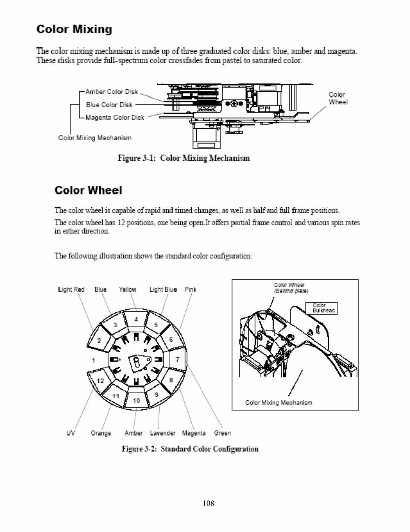
108
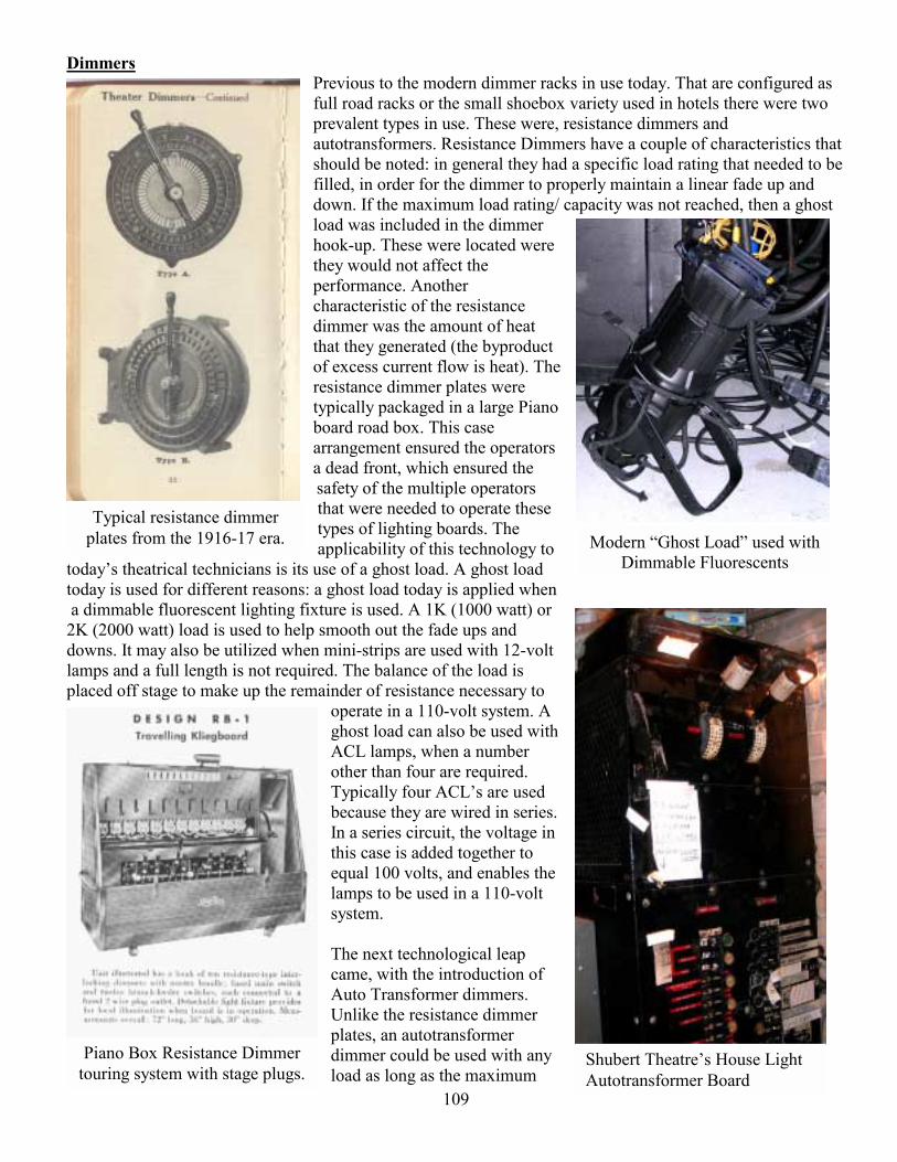
109
Typical resistance dimmer plates from the 1916-17 era.
Piano Box Resistance Dimmer touring system with stage plugs.
Shubert Theatres House Light Autotransformer Board
Modern Ghost Load used with Dimmable Fluorescents
Dimmers Previous to the modern dimmer racks in use today. That are configured as full road racks or the small shoebox variety used in hotels there were two prevalent types in use. These were, resistance dimmers and autotransformers. Resistance Dimmers have a couple of characteristics that should be noted: in general they had a specific load rating that needed to be filled, in order for the dimmer to properly maintain a linear fade up and down. If the maximum load rating/ capacity was not reached, then a ghost load was included in the dimmer hook-up. These were located were they would not affect the performance. Another characteristic of the resistance dimmer was the amount of heat that they generated (the byproduct of excess current flow is heat). The resistance dimmer plates were typically packaged in a large Piano board road box. This case arrangement ensured the operators a dead front, which ensured the safety of the multiple operators that were needed to operate these types of lighting boards. The applicability of this technology to
todays theatrical technicians is its use of a ghost load. A ghost load today is used for different reasons: a ghost load today is applied when a dimmable fluorescent lighting fixture is used. A 1K (1000 watt) or 2K (2000 watt) load is used to help smooth out the fade ups and downs. It may also be utilized when mini-strips are used with 12-volt lamps and a full length is not required. The balance of the load is placed off stage to make up the remainder of resistance necessary to
operate in a 110-volt system. A ghost load can also be used with ACL lamps, when a number other than four are required. Typically four ACLs are used because they are wired in series. In a series circuit, the voltage in this case is added together to equal 100 volts, and enables the lamps to be used in a 110-volt system. The next technological leap came, with the introduction of Auto Transformer dimmers. Unlike the resistance dimmer plates, an autotransformer dimmer could be used with any load as long as the maximum
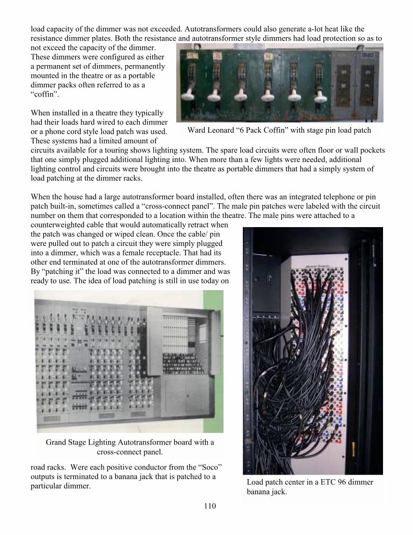
110
Ward Leonard 6 Pack Coffin with stage pin load patch
Grand Stage Lighting Autotransformer board with a cross-connect panel.
Load patch center in a ETC 96 dimmer banana jack.
load capacity of the dimmer was not exceeded. Autotransformers could also generate a-lot heat like the resistance dimmer plates. Both the resistance and autotransformer style dimmers had load protection so as to not exceed the capacity of the dimmer. These dimmers were configured as either a permanent set of dimmers, permanently mounted in the theatre or as a portable dimmer packs often referred to as a coffin. When installed in a theatre they typically had their loads hard wired to each dimmer or a phone cord style load patch was used. These systems had a limited amount of circuits available for a touring shows lighting system. The spare load circuits were often floor or wall pockets that one simply plugged additional lighting into. When more than a few lights were needed, additional lighting control and circuits were brought into the theatre as portable dimmers that had a simply system of load patching at the dimmer racks. When the house had a large autotransformer board installed, often there was an integrated telephone or pin patch built-in, sometimes called a cross-connect panel. The male pin patches were labeled with the circuit number on them that corresponded to a location within the theatre. The male pins were attached to a counterweighted cable that would automatically retract when the patch was changed or wiped clean. Once the cable/ pin were pulled out to patch a circuit they were simply plugged into a dimmer, which was a female receptacle. That had its other end terminated at one of the autotransformer dimmers. By patching it the load was connected to a dimmer and was ready to use. The idea of load patching is still in use today on
road racks. Were each positive conductor from the Soco outputs is terminated to a banana jack that is patched to a particular dimmer.
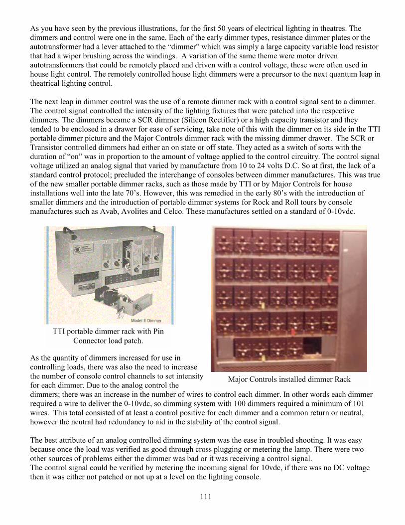
111
Major Controls installed dimmer Rack
TTI portable dimmer rack with Pin Connector load patch.
As you have seen by the previous illustrations, for the first 50 years of electrical lighting in theatres. The dimmers and control were one in the same. Each of the early dimmer types, resistance dimmer plates or the autotransformer had a lever attached to the dimmer which was simply a large capacity variable load resistor that had a wiper brushing across the windings. A variation of the same theme were motor driven autotransformers that could be remotely placed and driven with a control voltage, these were often used in house light control. The remotely controlled house light dimmers were a precursor to the next quantum leap in theatrical lighting control. The next leap in dimmer control was the use of a remote dimmer rack with a control signal sent to a dimmer. The control signal controlled the intensity of the lighting fixtures that were patched into the respective dimmers. The dimmers became a SCR dimmer (Silicon Rectifier) or a high capacity transistor and they tended to be enclosed in a drawer for ease of servicing, take note of this with the dimmer on its side in the TTI portable dimmer picture and the Major Controls dimmer rack with the missing dimmer drawer. The SCR or Transistor controlled dimmers had either an on state or off state. They acted as a switch of sorts with the duration of on was in proportion to the amount of voltage applied to the control circuitry. The control signal voltage utilized an analog signal that varied by manufacture from 10 to 24 volts D.C. So at first, the lack of a standard control protocol; precluded the interchange of consoles between dimmer manufactures. This was true of the new smaller portable dimmer racks, such as those made by TTI or by Major Controls for house installations well into the late 70s. However, this was remedied in the early 80s with the introduction of smaller dimmers and the introduction of portable dimmer systems for Rock and Roll tours by console manufactures such as Avab, Avolites and Celco. These manufactures settled on a standard of 0-10vdc.
As the quantity of dimmers increased for use in controlling loads, there was also the need to increase the number of console control channels to set intensity for each dimmer. Due to the analog control the dimmers; there was an increase in the number of wires to control each dimmer. In other words each dimmer required a wire to deliver the 0-10vdc, so dimming system with 100 dimmers required a minimum of 101 wires. This total consisted of at least a control positive for each dimmer and a common return or neutral, however the neutral had redundancy to aid in the stability of the control signal. The best attribute of an analog controlled dimming system was the ease in troubled shooting. It was easy because once the load was verified as good through cross plugging or metering the lamp. There were two other sources of problems either the dimmer was bad or it was receiving a control signal. The control signal could be verified by metering the incoming signal for 10vdc, if there was no DC voltage then it was either not patched or not up at a level on the lighting console.

112
NSI high-density dimmers.
Contemporary high-density Lepricon dimmers.
Strand CD 80 dimmer pack with thumb wheel addressing and full on buttons.
ETC 48 dimmer rack with pin patch.
Colortran dimmer rack Soco input and Cam Lock view
ETC AF (Advance Features) dimmer module
As the dimmer count rose in installations and for road use, space requirements became an increasing issue. Some of the first manufactures to address this problem were Strand, CAE, and NSI. CAE with the introduction of their Lepricon dimmer packs that contained six dimmers per pack, and Strand with their CD 80 dimmer packs that contained twelve dimmers, with the choice of analog or AMX 192.
The previous discussion of historical dimming types builds two ideas, first of which is load patching at a dimmer and the application of ghost loads used with dimmable fluorescents. With the introduction of electronic dimmers and the application of a control signal helped stimulate the reduction in physical size and increase the dimmer counts used in installations and in portable applications. With the higher dimmer count it became necessary to create a control scheme that relied upon a digital protocol to ease the wiring
burden in large systems. The DMX 512 digital protocol was created to full fill this need and is still in use today for intensity control.
The road racks that we use today contain a higher density of dimmers and use the DMX 512 standard. These racks are made in 96, 72, 48 or 24 dimmer rack configurations. The dimmer racks are populated by using a 19 rack mount dimmer pack like the Lepricon or NSI racks. Or using a dimmer module that may contain a single 5K (5000 watt) dimmer, a pair of dimmers, relay module or a fluorescent dimmer module. The dimmers racks that we receive on site to work with are usually made by ETC. However other manufactures such as Lepricon, NSI and Colortran make similar products. Contained in the dimmer racks are
various features. The larger dimmer racks will use an electronics module to manage features of the racks. Some of these are the type of dimmer modules, their order and location within the rack. DMX reception and whether it is being received by the A or B inputs, starting DMX address for the rack. These types of features are contained with in a module call a CEM on all ETC racks. In addition to the electronic modules, there are hardware elements that will vary slightly. Modern dimmer racks are built with Soco Pac screw type connectors, Edison convenience outlets, hot pockets and optional pin connectors that are parallel dimmer outputs. These connectors are often mounted on the back of the racks along
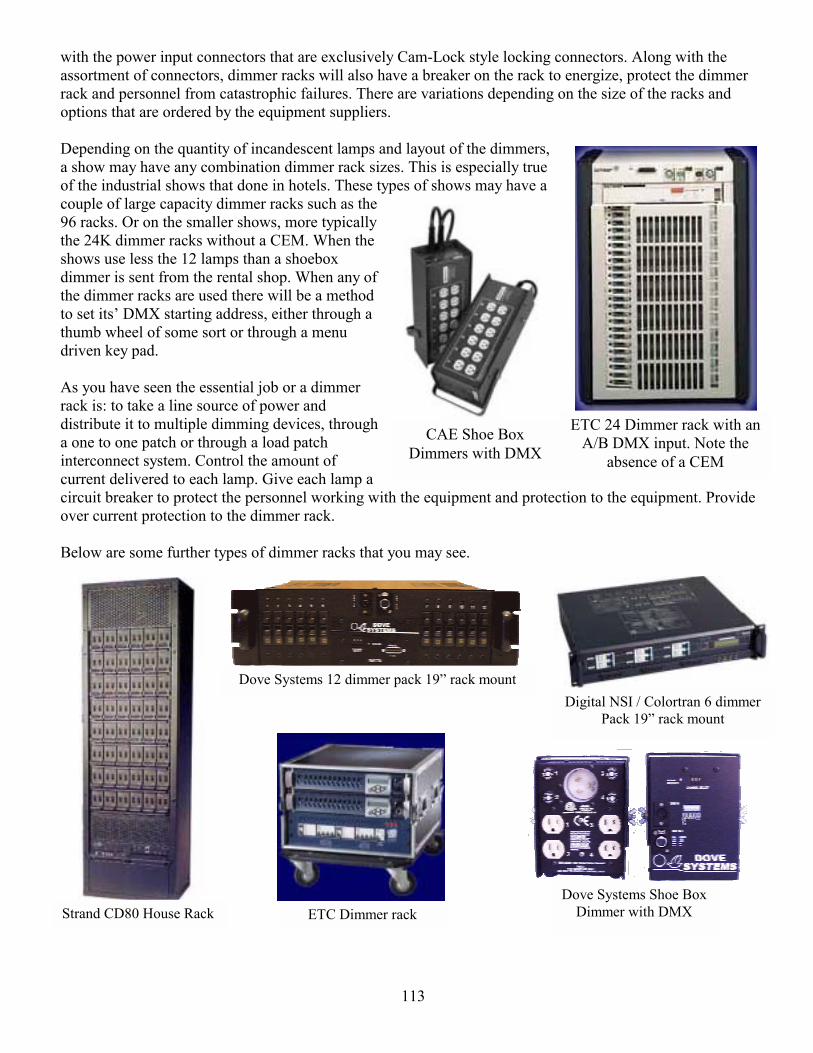
113
CAE Shoe Box Dimmers with DMX
Strand CD80 House Rack
Dove Systems 12 dimmer pack 19 rack mount Digital NSI / Colortran 6 dimmer
Pack 19 rack mount
ETC Dimmer rack Dove Systems Shoe Box
Dimmer with DMX
ETC 24 Dimmer rack with an A/B DMX input. Note the
absence of a CEM
with the power input connectors that are exclusively Cam-Lock style locking connectors. Along with the assortment of connectors, dimmer racks will also have a breaker on the rack to energize, protect the dimmer rack and personnel from catastrophic failures. There are variations depending on the size of the racks and options that are ordered by the equipment suppliers. Depending on the quantity of incandescent lamps and layout of the dimmers, a show may have any combination dimmer rack sizes. This is especially true of the industrial shows that done in hotels. These types of shows may have a couple of large capacity dimmer racks such as the 96 racks. Or on the smaller shows, more typically the 24K dimmer racks without a CEM. When the shows use less the 12 lamps than a shoebox dimmer is sent from the rental shop. When any of the dimmer racks are used there will be a method to set its DMX starting address, either through a thumb wheel of some sort or through a menu driven key pad. As you have seen the essential job or a dimmer rack is: to take a line source of power and distribute it to multiple dimming devices, through a one to one patch or through a load patch interconnect system. Control the amount of current delivered to each lamp. Give each lamp a circuit breaker to protect the personnel working with the equipment and protection to the equipment. Provide over current protection to the dimmer rack. Below are some further types of dimmer racks that you may see.

114
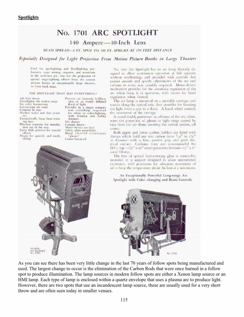
115
Spotlights
As you can see there has been very little change in the last 70 years of follow spots being manufactured and used. The largest change to occur is the elimination of the Carbon Rods that were once burned in a follow spot to produce illumination. The lamp sources in modern follow spots are either a Xenon lamp source or an HMI lamp. Each type of lamp is enclosed within a quartz envelope that uses a plasma arc to produce light. However, there are two spots that use an incandescent lamp source, these are usually used for a very short throw and are often seen today in smaller venues.
116
When one is called to operate a follow spot, you will be required to use a headset to listen to ques being called by either a Lighting Director as done on most Arena shows. Or a Lead follow spot operator/Roadie under contact on theatrical show. Typically you will see one of three manufactures lamps as front lights: Strong, Lycian and Robert Juliat. Lycian uses a variant of their front light as a Side and truss light. All the previous spot lights will have the following controls in common: Color boomerang mounted towards the front of the light, intensity dowser or iris, beam size iris, a chopper and a slot on the top of the unit for color or effects. The Juliats will also have three additional controls: frost that may be dissolved in or out, 3400° Kelvin color correction and blue correction for video usage. They also have a bump button on some models used in conjunction with the intensity iris. There will also be a trombone on most all spots that will be able to set the maximum beam diameter on stage. When a stage call is accepted to run a follow spot you will work in under a Lighting Director in concert venues or Industrial Shows or. In theatrical shows, a Lead Follow Spot operator. Either person will typically have a set list of ques. These ques are called to a follow spot by assigning a number to the position you work at. You will also receive color information by the number it occupies in the boomerang. The spot boomerangs are numbered from Frame one, which is the closest to Frame six; the farthest away from the operator. The intensity value is given as a percentage except out, being no light emitted from the front of the lamp. Otherwise all other intensities are given as a percentage to 100% or full. Intensity changes will be asked for as a bump which is a 0 count or in time. A timed fade may be a two to fifteen count fade up or out. When a bump out command is given, means a 0 count to go to 0 intensity. In addition to the calls on intensity values, you can be called upon to ride the intensity iris in order to correct for the distance you are from your spot position. The reason for this is the person you are following is perceived to be illuminated at the same relative level. The chopper may also be used in conjunction with the intensity dowser on the Strong and Lycian brand follow spots. This is useful, when the beam iris is open to cover more than two people. The chopper is used to make a shutter cut from the top and bottom of the beam on stage like a Leko. Another, necessary control to use is the beam Iris, which adjust the size beam on light on stage. The person calling the follow spot ques will tell you the size. The size is stated as follows and is the literal meaning. Full body, half body, knee and head shot. You will be asked to do these in time, the same as intensity changes. In addition to the simple beam sizes assigned to you, riding the beam size to keep the same size, as the actor moves will also be required of you. The person calling spot ques will either work off a Set List as done for Rock Shows or a more sophisticated means for Theatrical Shows. A spot caller on a theatrical show will often use a list with all the information need to call the Show. The following are a couple of examples of this. However, when the que list is given to an operator, it may resemble the one the caller uses or broken down to each follow spot by lamp number. On smaller shows, the spot caller will simply call the show to you, with expectations that each show will improve. The following pages show master call sheets that is used for theatrical shows. There is a que number given as a reference, a brief description, and the action required by each light. Typically the person calling the show will give you a set-up in advance of the next ques, followed by a standby when one able and always a Go.
117
LION KING CHEETAH TOUR
SPOT CALLING SCRIPT
CUE Description Sc.1 Circle of Life SPOTS 5,1,2 FR.3 SPOTS 3,4
FR. 2-4 102.5 Rafiki after 1st line 5 25% RAFIKI H DSL 105.5 W/Q 105.5 (sun rises) 5 WIDEN to 3/4 BUILD TO 75% 109 Cheetah enters SR 110 5 cts after Cue 110 5 TIGHTEN to AVOID
PROCESSION After Cheetah face wash 111.3 end Rafiki solo 5 F/O 3ct (5 chng FR.2-DF) 1 100% SOLOIST SL W 2 100% SOLOIST SR W 111.4 Mufasa/Sarabi up rock 2nd lap w/rock 112.6 w/ Q112.6 -(vari*lite up) 112.7 Soloists turn US for
group bow towards Rock 1,2 F/O (1,2 chng FR.2-DF)
Page from Lion King” Spot Book, with all lamps and actions for each lamp.

118
Comparing the two Master call sheets you will see notice one is easier to read. The All Shook UP spot sheet was also the spot que list that each operator was given. I believe you will find it hard to read, and there fore, much more difficult to extract information out of quickly during a show. Much of the confusion can be attributed to the size of the text, which was chosen to get more information on each page. Because, if you get lost during a show, or wish to look ahead at your next ques, a-lot of time will be spent finding your place. You will also notice the hand written notes that were made for changes. Often times there are errors or changes that do not make it onto the sheets, which the operator uses. However the master sheets are the final arbitrator to any questions.
119
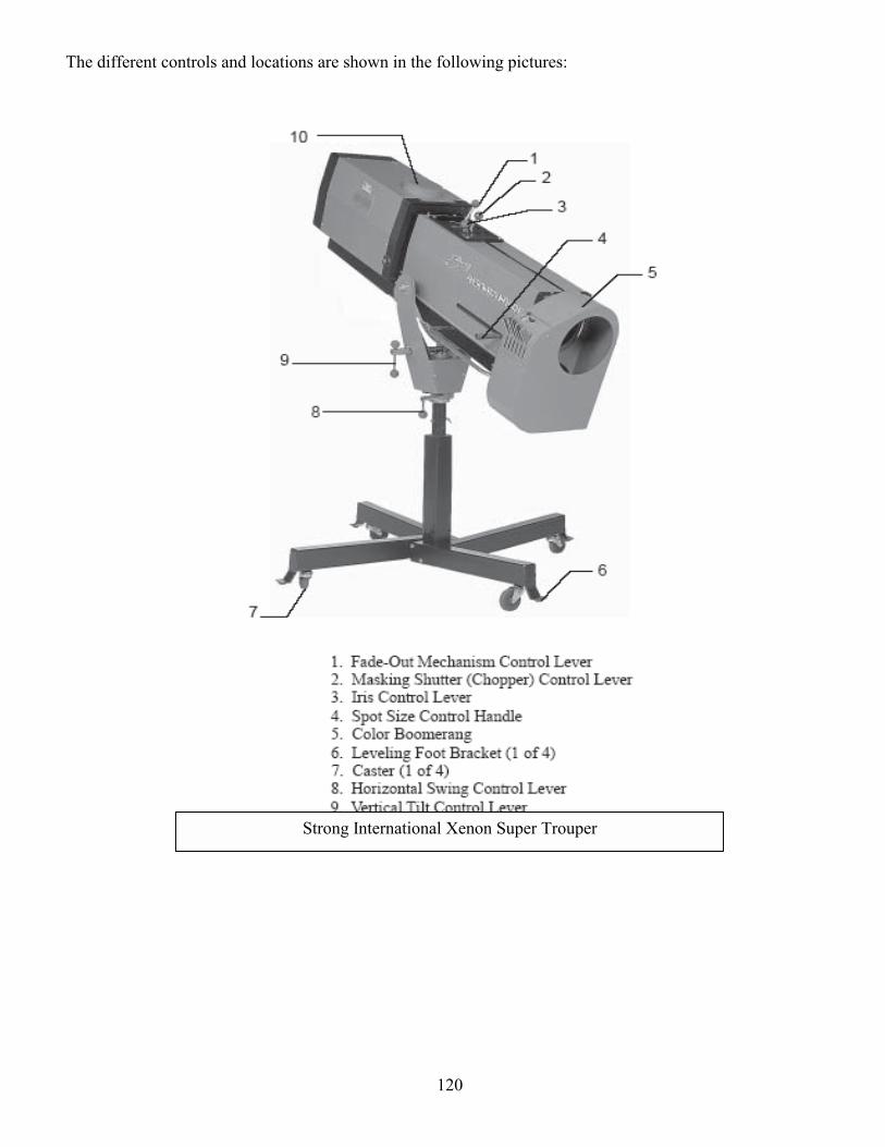
120
Strong International Xenon Super Trouper
The different controls and locations are shown in the following pictures:
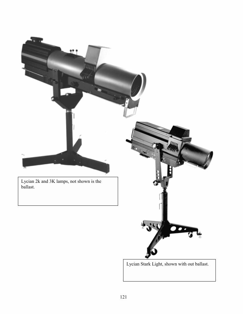
121
Lycian 2k and 3K lamps, not shown is the ballast.
Lycian Stark Light, shown with out ballast.
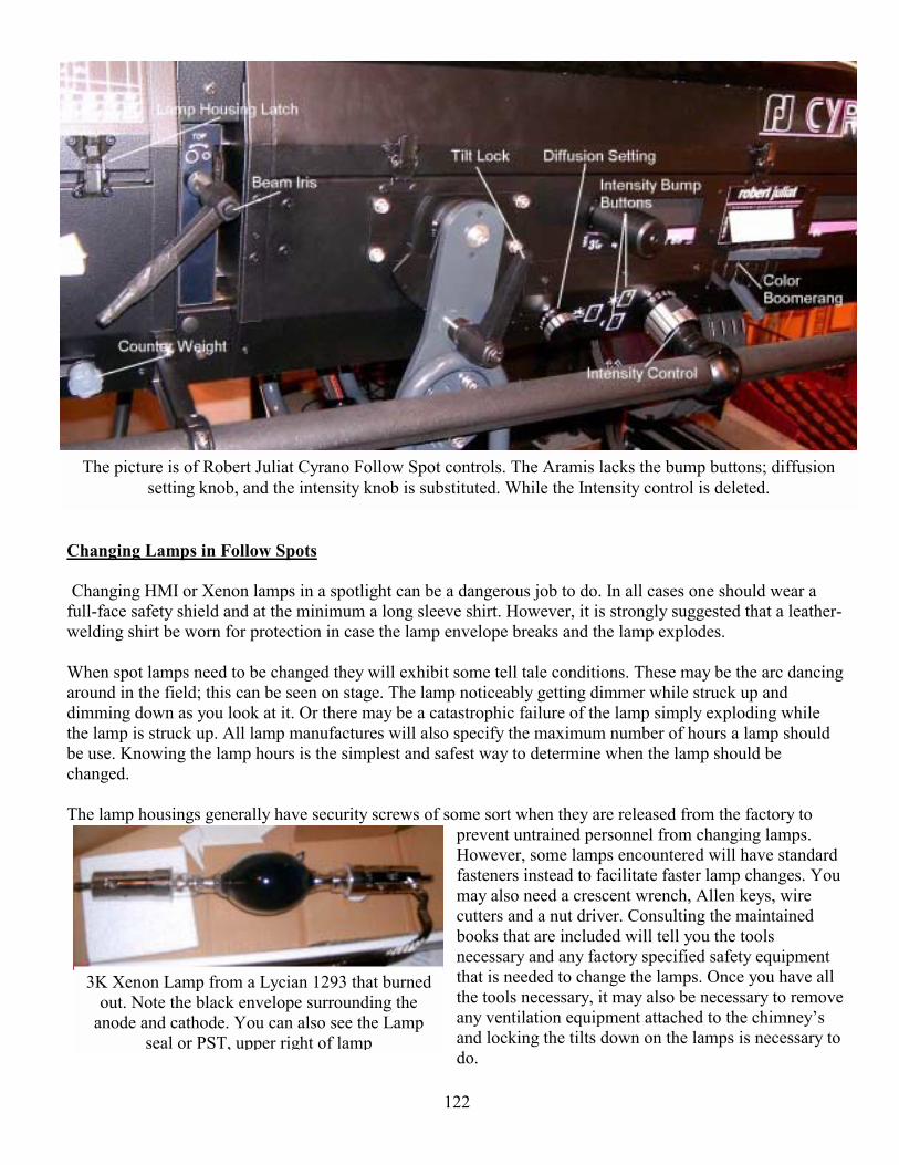
122
3K Xenon Lamp from a Lycian 1293 that burned out. Note the black envelope surrounding the
anode and cathode. You can also see the Lamp seal or PST, upper right of lamp
The picture is of Robert Juliat Cyrano Follow Spot controls. The Aramis lacks the bump buttons; diffusion setting knob, and the intensity knob is substituted. While the Intensity control is deleted.
Changing Lamps in Follow Spots Changing HMI or Xenon lamps in a spotlight can be a dangerous job to do. In all cases one should wear a full-face safety shield and at the minimum a long sleeve shirt. However, it is strongly suggested that a leather-welding shirt be worn for protection in case the lamp envelope breaks and the lamp explodes. When spot lamps need to be changed they will exhibit some tell tale conditions. These may be the arc dancing around in the field; this can be seen on stage. The lamp noticeably getting dimmer while struck up and dimming down as you look at it. Or there may be a catastrophic failure of the lamp simply exploding while the lamp is struck up. All lamp manufactures will also specify the maximum number of hours a lamp should be use. Knowing the lamp hours is the simplest and safest way to determine when the lamp should be changed. The lamp housings generally have security screws of some sort when they are released from the factory to
prevent untrained personnel from changing lamps. However, some lamps encountered will have standard fasteners instead to facilitate faster lamp changes. You may also need a crescent wrench, Allen keys, wire cutters and a nut driver. Consulting the maintained books that are included will tell you the tools necessary and any factory specified safety equipment that is needed to change the lamps. Once you have all the tools necessary, it may also be necessary to remove any ventilation equipment attached to the chimneys and locking the tilts down on the lamps is necessary to do.
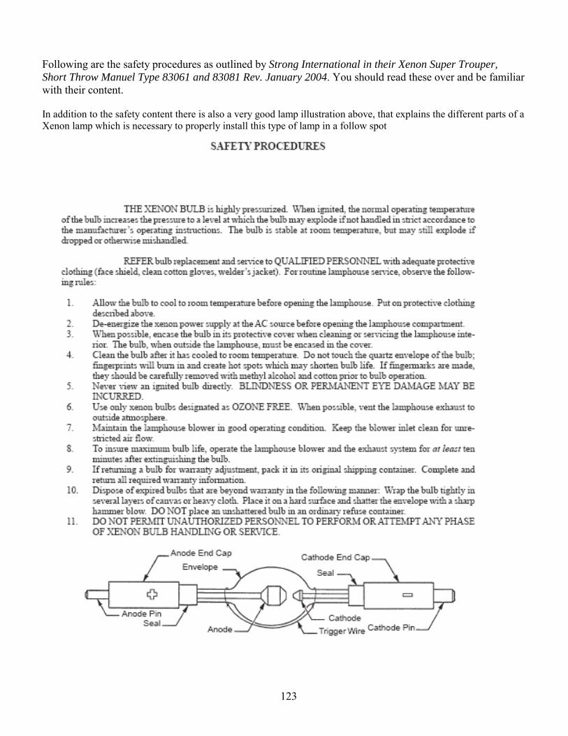
123
Following are the safety procedures as outlined by Strong International in their Xenon Super Trouper, Short Throw Manuel Type 83061 and 83081 Rev. January 2004. You should read these over and be familiar with their content. In addition to the safety content there is also a very good lamp illustration above, that explains the different parts of a Xenon lamp which is necessary to properly install this type of lamp in a follow spot
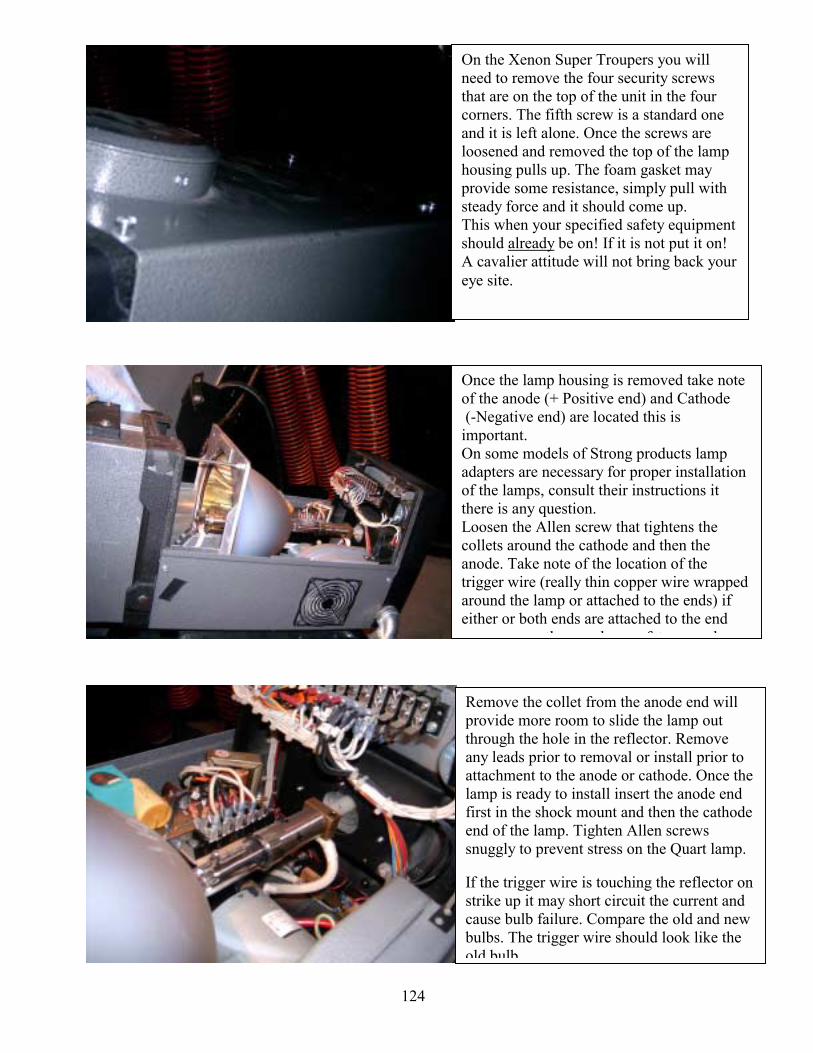
124
Once the lamp housing is removed take note of the anode (+ Positive end) and Cathode (-Negative end) are located this is important. On some models of Strong products lamp adapters are necessary for proper installation of the lamps, consult their instructions it there is any question. Loosen the Allen screw that tightens the collets around the cathode and then the anode. Take note of the location of the trigger wire (really thin copper wire wrapped around the lamp or attached to the ends) if either or both ends are attached to the end
th d f t d
On the Xenon Super Troupers you will need to remove the four security screws that are on the top of the unit in the four corners. The fifth screw is a standard one and it is left alone. Once the screws are loosened and removed the top of the lamp housing pulls up. The foam gasket may provide some resistance, simply pull with steady force and it should come up. This when your specified safety equipment should already be on! If it is not put it on! A cavalier attitude will not bring back your eye site.
Remove the collet from the anode end will provide more room to slide the lamp out through the hole in the reflector. Remove any leads prior to removal or install prior to attachment to the anode or cathode. Once the lamp is ready to install insert the anode end first in the shock mount and then the cathode end of the lamp. Tighten Allen screws snuggly to prevent stress on the Quart lamp. If the trigger wire is touching the reflector on strike up it may short circuit the current and cause bulb failure. Compare the old and new bulbs. The trigger wire should look like the old bulb
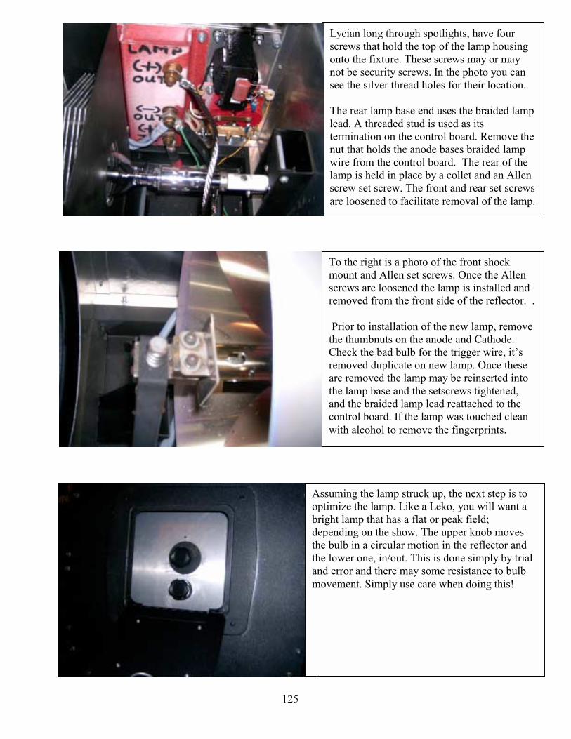
125
Lycian long through spotlights, have four screws that hold the top of the lamp housing onto the fixture. These screws may or may not be security screws. In the photo you can see the silver thread holes for their location. The rear lamp base end uses the braided lamp lead. A threaded stud is used as its termination on the control board. Remove the nut that holds the anode bases braided lamp wire from the control board. The rear of the lamp is held in place by a collet and an Allen screw set screw. The front and rear set screws are loosened to facilitate removal of the lamp.
To the right is a photo of the front shock mount and Allen set screws. Once the Allen screws are loosened the lamp is installed and removed from the front side of the reflector. . Prior to installation of the new lamp, remove the thumbnuts on the anode and Cathode. Check the bad bulb for the trigger wire, its removed duplicate on new lamp. Once these are removed the lamp may be reinserted into the lamp base and the setscrews tightened, and the braided lamp lead reattached to the control board. If the lamp was touched clean with alcohol to remove the fingerprints.
Assuming the lamp struck up, the next step is to optimize the lamp. Like a Leko, you will want a bright lamp that has a flat or peak field; depending on the show. The upper knob moves the bulb in a circular motion in the reflector and the lower one, in/out. This is done simply by trial and error and there may some resistance to bulb movement. Simply use care when doing this!
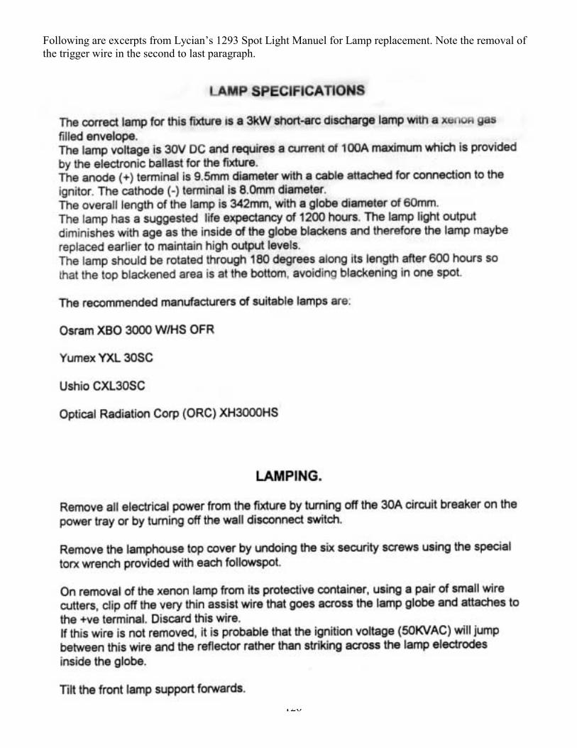
126
Following are excerpts from Lycians 1293 Spot Light Manuel for Lamp replacement. Note the removal of the trigger wire in the second to last paragraph.
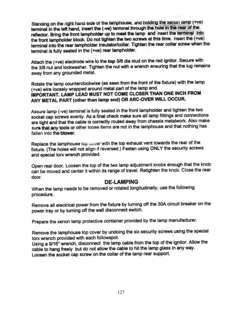
127
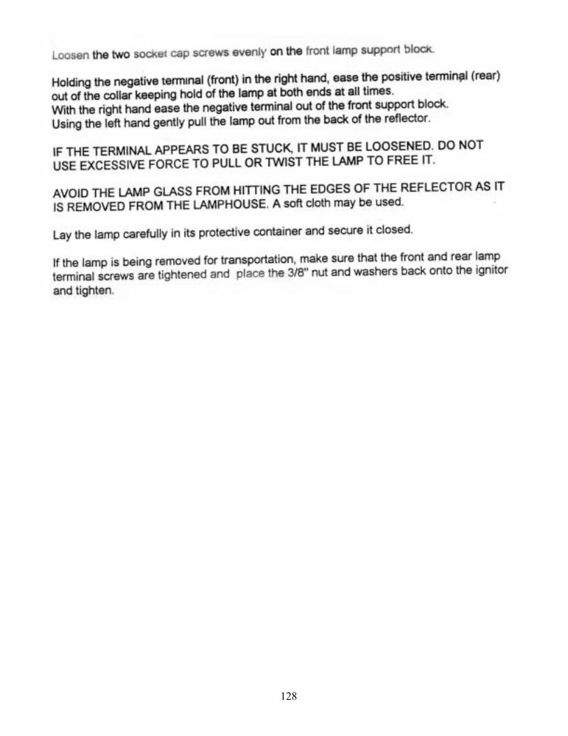
128
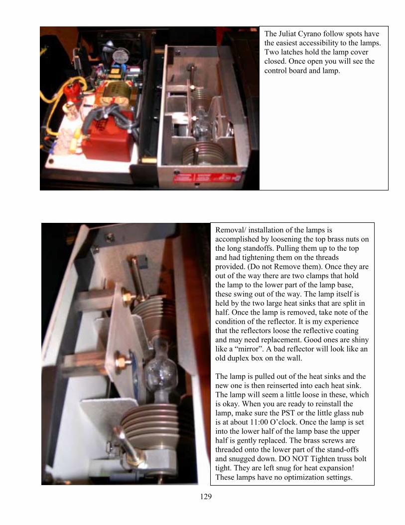
129
The Juliat Cyrano follow spots have the easiest accessibility to the lamps. Two latches hold the lamp cover closed. Once open you will see the control board and lamp.
Removal/ installation of the lamps is accomplished by loosening the top brass nuts on the long standoffs. Pulling them up to the top and had tightening them on the threads provided. (Do not Remove them). Once they are out of the way there are two clamps that hold the lamp to the lower part of the lamp base, these swing out of the way. The lamp itself is held by the two large heat sinks that are split in half. Once the lamp is removed, take note of the condition of the reflector. It is my experience that the reflectors loose the reflective coating and may need replacement. Good ones are shiny like a mirror. A bad reflector will look like an old duplex box on the wall. The lamp is pulled out of the heat sinks and the new one is then reinserted into each heat sink. The lamp will seem a little loose in these, which is okay. When you are ready to reinstall the lamp, make sure the PST or the little glass nub is at about 11:00 Oclock. Once the lamp is set into the lower half of the lamp base the upper half is gently replaced. The brass screws are threaded onto the lower part of the stand-offs and snugged down. DO NOT Tighten truss bolt tight. They are left snug for heat expansion! These lamps have no optimization settings.
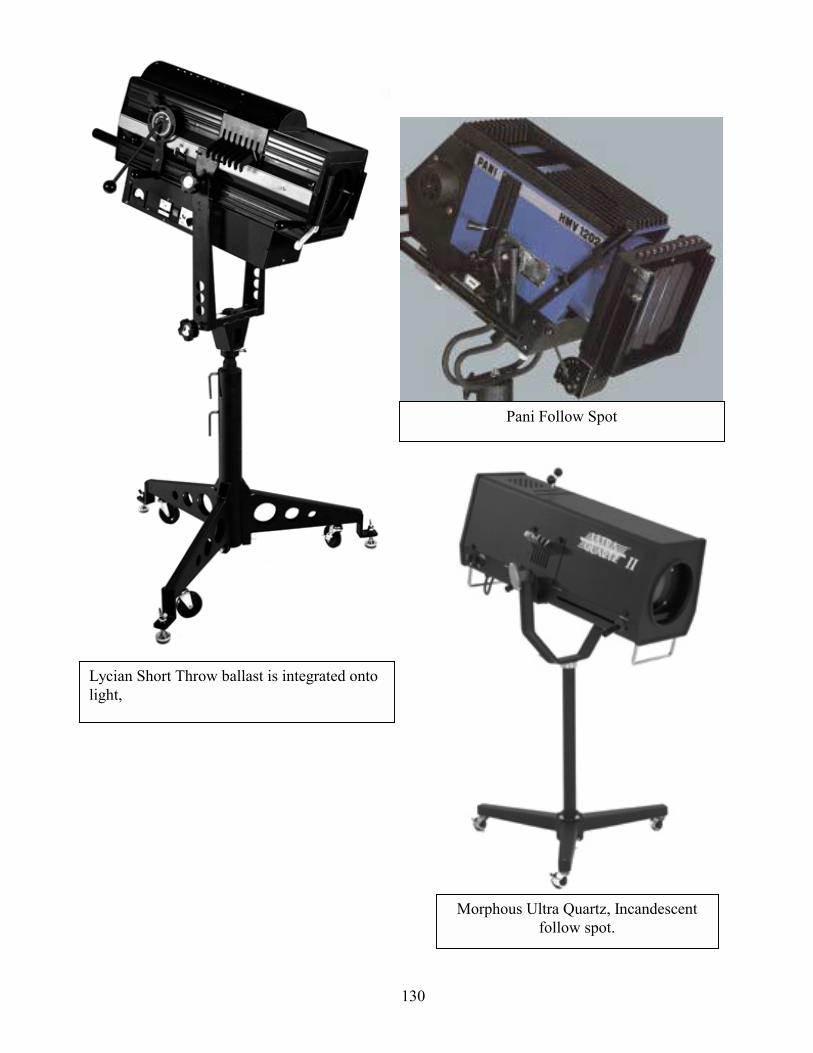
130
Lycian Short Throw ballast is integrated onto light,
Pani Follow Spot
Morphous Ultra Quartz, Incandescent follow spot.

131
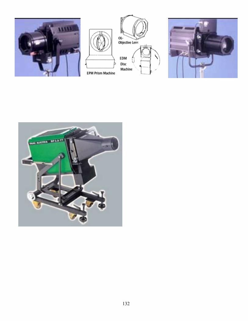
132
133
Below is a portion of table 400.4 that lists some of the applicable cable for theatrical use See APENDIX for more detail and if further detail is necessary consult the National Electrical Code 2002.
Nominal Insulation Thickness
Trade Name
Type Letter Voltage
AWG or
kcmil Number of conductors Insulation
AWG or kcmil mm mils
Braid on Each
ConductorOuter
Covering Use SJOW
See Note 13 300 Damp
and wet locations
SJOO 300 Damp locations
SJOOW See Note 13
300
Thermoset 18-12 0.76 30 Thermoset
Damp and wet locations
SJT 300 Damp locations
SJTW See Note 13
300
10 1.14 45 Thermo-plastic
Damp and wet locations
SJTO 300 Damp locations
SJTOW See Note 13
300
Thermoplastic
Damp and wet locations
SJTOO 300 Damp locations
Junior hard
service cord
SJTOOW See Note 13
300
18-10 2-6
Oil-resistant thermo-plastic
18-12 0.76 30
None
Oil-resistant thermo-plastic
Pendant or
portable
Damp and wet locations
Hard usage
SO See Note 4
600 Damp locations
SOW See Note 4
See Note 13 600
Thermoset 18-16 0.76 30
Damp and wet locations
SOO See Note 4
600 Damp locations
Hard Service Cord
SOOW See Note 4
See Note 13 600
18-2 2 or more
Oil-resistant thermoset
14-10 8-2
1.14 1.52
45 60
Oil-resistant
thermoset
Pendant or
portable
Damp and wet locations
Extra hard usage
A portion of table 400.4 that lists applicable cable for theatrical use. See APPENDIX for more detail.
60°C (140°F)
75°C (167°F)
90°C (194°F)
Size AWG or kcmil D1 E2 F3 D1 E2 F3 D1 E2 F3
12 31 26 37 31 42 35 10 44 37 52 43 59 49 8 60 55 48 70 65 57 80 74 65 6 80 72 63 95 88 77 105 99 87 4 105 96 84 125 115 101 140 130 114 3 120 113 99 145 135 118 165 152 133 2 140 128 112 170 152 133 190 174 152 1 165 150 131 195 178 156 220 202 177
1/0 195 173 151 230 207 181 260 234 205 2/0 225 199 174 265 238 208 300 271 237 3/0 260 230 201 310 275 241 350 313 274 4/0 300 265 232 360 317 277 405 361 316
134
The exemplary cables are permitted to be use for such things as: wiring of luminaries (lighting fixtures), connection of portable lamps, portable and mobile appliances, data processing cables, or connection to moving parts. Obviously plugs may be attached to both ends. You should not use flexible cables though to substitute for permanent wiring in structures. Also splices within a flexible cord length should not be used when a cord is damaged replace it. Protecting the cords from damage is relatively simply use bushings in conduit boxes when one making a portable receptacle box, use rubber matting and the like and avoid running cable around sharp objects without protection to avoid damage. Also a flexible cable may be used for chain-supported luminaries (lighting fixtures). More detail can be found in Article 400.7 through 400.11 in the National Electrical Code 2002. While making cables, hooking-up to service panels or the like you will be called upon to identify load carrying conductors, usually a solid color or with tracer lines/ stripes. You should also be able to identify with some certainty the ground. Like all things commonly used in electricity a standard is established by the NEC. Article 250.119 defines the identification of equipment grounding conductors.
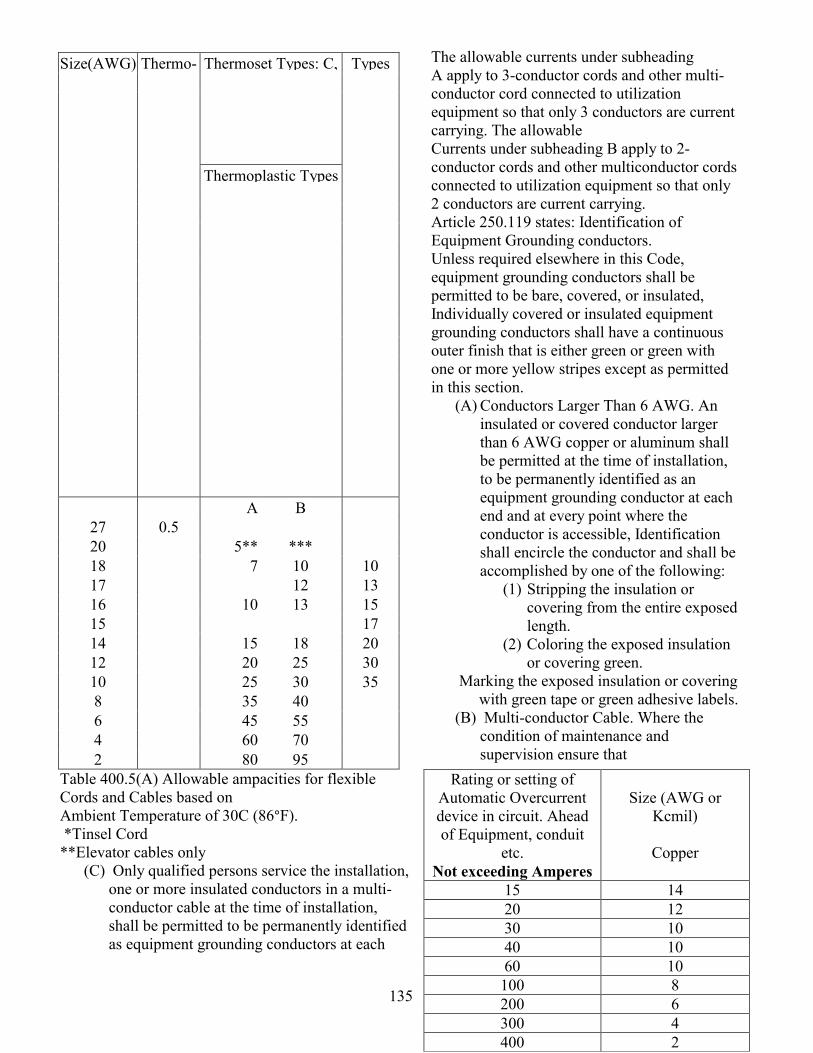
135
Table 400.5(A) Allowable ampacities for flexible Cords and Cables based on Ambient Temperature of 30C (86°F). *Tinsel Cord **Elevator cables only
The allowable currents under subheading A apply to 3-conductor cords and other multi-conductor cord connected to utilization equipment so that only 3 conductors are current carrying. The allowable Currents under subheading B apply to 2-conductor cords and other multiconductor cords connected to utilization equipment so that only 2 conductors are current carrying. Article 250.119 states: Identification of Equipment Grounding conductors. Unless required elsewhere in this Code, equipment grounding conductors shall be permitted to be bare, covered, or insulated, Individually covered or insulated equipment grounding conductors shall have a continuous outer finish that is either green or green with one or more yellow stripes except as permitted in this section.
(A) Conductors Larger Than 6 AWG. An insulated or covered conductor larger than 6 AWG copper or aluminum shall be permitted at the time of installation, to be permanently identified as an equipment grounding conductor at each end and at every point where the conductor is accessible, Identification shall encircle the conductor and shall be accomplished by one of the following:
(1) Stripping the insulation or covering from the entire exposed length.
(2) Coloring the exposed insulation or covering green.
Marking the exposed insulation or covering with green tape or green adhesive labels.
(B) Multi-conductor Cable. Where the condition of maintenance and supervision ensure that
(C) Only qualified persons service the installation, one or more insulated conductors in a multi-conductor cable at the time of installation, shall be permitted to be permanently identified as equipment grounding conductors at each
Thermoset Types: C, Size(AWG) Thermo-
Thermoplastic Types
Types
A B 27 0.5 20 5** *** 18 7 10 10 17 12 13 16 10 13 15 15 17 14 15 18 20 12 20 25 30 10 25 30 35 8 35 40 6 45 55 4 60 70 2 80 95
Rating or setting of Automatic Overcurrent device in circuit. Ahead of Equipment, conduit
etc. Not exceeding Amperes
Size (AWG or
Kcmil)
Copper
15 14 20 12 30 10 40 10 60 10 100 8 200 6 300 4 400 2
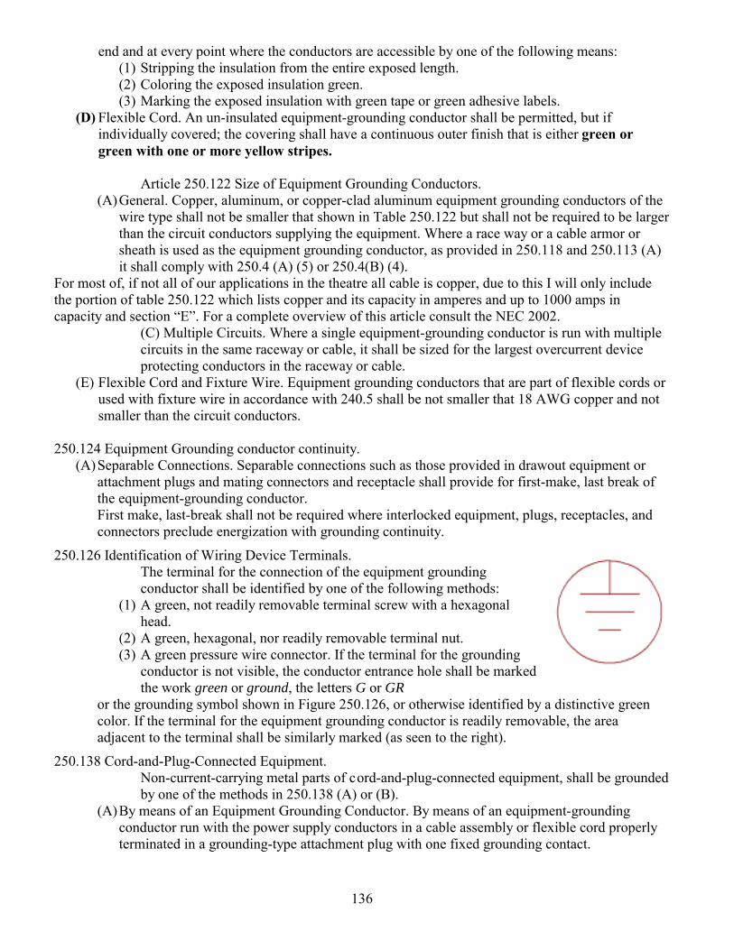
136
end and at every point where the conductors are accessible by one of the following means: (1) Stripping the insulation from the entire exposed length. (2) Coloring the exposed insulation green. (3) Marking the exposed insulation with green tape or green adhesive labels.
(D) Flexible Cord. An un-insulated equipment-grounding conductor shall be permitted, but if individually covered; the covering shall have a continuous outer finish that is either green or green with one or more yellow stripes.
Article 250.122 Size of Equipment Grounding Conductors.
(A) General. Copper, aluminum, or copper-clad aluminum equipment grounding conductors of the wire type shall not be smaller that shown in Table 250.122 but shall not be required to be larger than the circuit conductors supplying the equipment. Where a race way or a cable armor or sheath is used as the equipment grounding conductor, as provided in 250.118 and 250.113 (A) it shall comply with 250.4 (A) (5) or 250.4(B) (4).
For most of, if not all of our applications in the theatre all cable is copper, due to this I will only include the portion of table 250.122 which lists copper and its capacity in amperes and up to 1000 amps in capacity and section E. For a complete overview of this article consult the NEC 2002.
(C) Multiple Circuits. Where a single equipment-grounding conductor is run with multiple circuits in the same raceway or cable, it shall be sized for the largest overcurrent device protecting conductors in the raceway or cable.
(E) Flexible Cord and Fixture Wire. Equipment grounding conductors that are part of flexible cords or used with fixture wire in accordance with 240.5 shall be not smaller that 18 AWG copper and not smaller than the circuit conductors.
250.124 Equipment Grounding conductor continuity.
(A) Separable Connections. Separable connections such as those provided in drawout equipment or attachment plugs and mating connectors and receptacle shall provide for first-make, last break of the equipment-grounding conductor. First make, last-break shall not be required where interlocked equipment, plugs, receptacles, and connectors preclude energization with grounding continuity.
250.126 Identification of Wiring Device Terminals. The terminal for the connection of the equipment grounding conductor shall be identified by one of the following methods:
(1) A green, not readily removable terminal screw with a hexagonal head.
(2) A green, hexagonal, nor readily removable terminal nut. (3) A green pressure wire connector. If the terminal for the grounding
conductor is not visible, the conductor entrance hole shall be marked the work green or ground, the letters G or GR
or the grounding symbol shown in Figure 250.126, or otherwise identified by a distinctive green color. If the terminal for the equipment grounding conductor is readily removable, the area adjacent to the terminal shall be similarly marked (as seen to the right).
250.138 Cord-and-Plug-Connected Equipment. Non-current-carrying metal parts of c ord-and-plug-connected equipment, shall be grounded by one of the methods in 250.138 (A) or (B).
(A) By means of an Equipment Grounding Conductor. By means of an equipment-grounding conductor run with the power supply conductors in a cable assembly or flexible cord properly terminated in a grounding-type attachment plug with one fixed grounding contact.
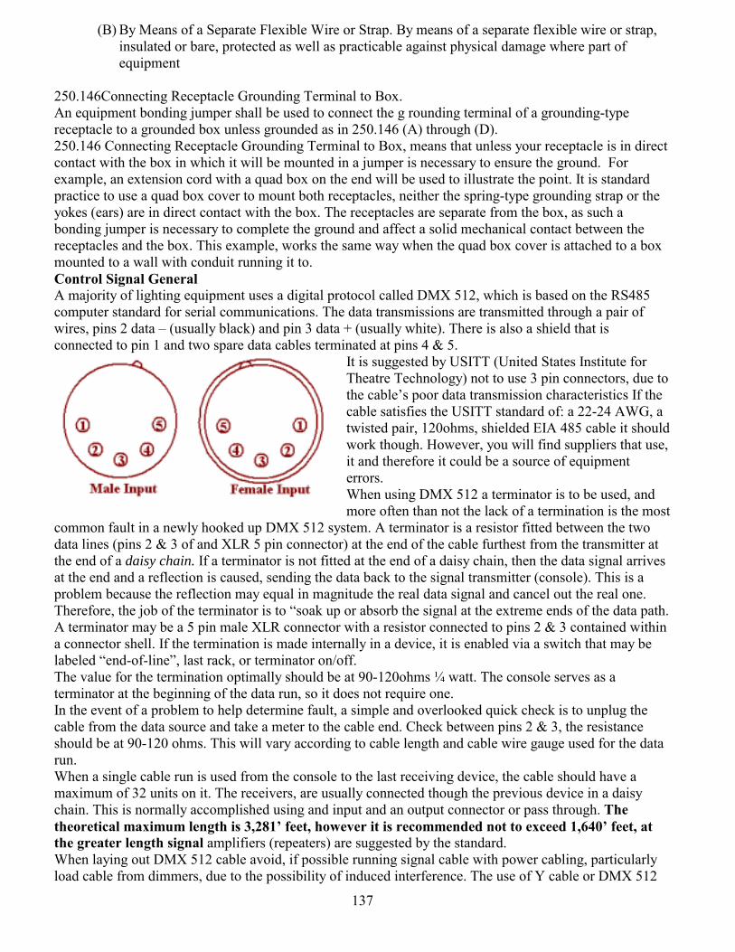
137
(B) By Means of a Separate Flexible Wire or Strap. By means of a separate flexible wire or strap, insulated or bare, protected as well as practicable against physical damage where part of equipment
250.146Connecting Receptacle Grounding Terminal to Box. An equipment bonding jumper shall be used to connect the g rounding terminal of a grounding-type receptacle to a grounded box unless grounded as in 250.146 (A) through (D). 250.146 Connecting Receptacle Grounding Terminal to Box, means that unless your receptacle is in direct contact with the box in which it will be mounted in a jumper is necessary to ensure the ground. For example, an extension cord with a quad box on the end will be used to illustrate the point. It is standard practice to use a quad box cover to mount both receptacles, neither the spring-type grounding strap or the yokes (ears) are in direct contact with the box. The receptacles are separate from the box, as such a bonding jumper is necessary to complete the ground and affect a solid mechanical contact between the receptacles and the box. This example, works the same way when the quad box cover is attached to a box mounted to a wall with conduit running it to. Control Signal General A majority of lighting equipment uses a digital protocol called DMX 512, which is based on the RS485 computer standard for serial communications. The data transmissions are transmitted through a pair of wires, pins 2 data (usually black) and pin 3 data + (usually white). There is also a shield that is connected to pin 1 and two spare data cables terminated at pins 4 & 5.
It is suggested by USITT (United States Institute for Theatre Technology) not to use 3 pin connectors, due to the cables poor data transmission characteristics If the cable satisfies the USITT standard of: a 22-24 AWG, a twisted pair, 120ohms, shielded EIA 485 cable it should work though. However, you will find suppliers that use, it and therefore it could be a source of equipment errors. When using DMX 512 a terminator is to be used, and more often than not the lack of a termination is the most
common fault in a newly hooked up DMX 512 system. A terminator is a resistor fitted between the two data lines (pins 2 & 3 of and XLR 5 pin connector) at the end of the cable furthest from the transmitter at the end of a daisy chain. If a terminator is not fitted at the end of a daisy chain, then the data signal arrives at the end and a reflection is caused, sending the data back to the signal transmitter (console). This is a problem because the reflection may equal in magnitude the real data signal and cancel out the real one. Therefore, the job of the terminator is to soak up or absorb the signal at the extreme ends of the data path. A terminator may be a 5 pin male XLR connector with a resistor connected to pins 2 & 3 contained within a connector shell. If the termination is made internally in a device, it is enabled via a switch that may be labeled end-of-line, last rack, or terminator on/off. The value for the termination optimally should be at 90-120ohms ¼ watt. The console serves as a terminator at the beginning of the data run, so it does not require one. In the event of a problem to help determine fault, a simple and overlooked quick check is to unplug the cable from the data source and take a meter to the cable end. Check between pins 2 & 3, the resistance should be at 90-120 ohms. This will vary according to cable length and cable wire gauge used for the data run. When a single cable run is used from the console to the last receiving device, the cable should have a maximum of 32 units on it. The receivers, are usually connected though the previous device in a daisy chain. This is normally accomplished using and input and an output connector or pass through. The theoretical maximum length is 3,281 feet, however it is recommended not to exceed 1,640 feet, at the greater length signal amplifiers (repeaters) are suggested by the standard. When laying out DMX 512 cable avoid, if possible running signal cable with power cabling, particularly load cable from dimmers, due to the possibility of induced interference. The use of Y cable or DMX 512
138
twofers is not recommended because it introduces reflections and causes signal problems. A splitter amplifier can be used to create two different branches for the control data to be sent on. Another source of interference is radio transmissions that may cause data errors. Address setting All DMX 512 devices, except those that read all 512 channels have a way to set their addresses to respond to que data transmitted by a control console. One method is to employ a base or starting address, where the device will start with that address for each sequential dimmer or parameters contained in that device. Digital display and keys, these generally may use any starting address in the first universe of DMX control channels, were the address settings are one on many menu driven selections that may be made. Thumbwheel switches are another means to address a device, which is very simple to use and allow direct access to the address to be set. The thumb wheels are usually in set of three and one simply spins the thumb wheel set an address, due to the numerical range built into a thumbwheel, addresss may be set from 000-999. However, not all numerical combinations may be valid and may set test modes are give you universe off sets for more address flexibility. Dipswitches are another popular means to set an address. These small rocker switches are grouped in banks and each switch is given a numerical weight and is either on or off. This scheme is not universally implemented by all manufactures in the same way. However a general rule is: switch 1=address 1, switch 2=address 2, switch 3=address 4, switch 4= address 8, switch 5= address 16, switch 6= address 32, switch 7= address 64, switch 8= address 128, switch 9= address 256. Using the first nine addresses, as an example will illustrate this. Note: it is assumed that using the USITT binary address scheme, that address one (1) is all dipswitches as off or 0. Also, the addresses may either start from the left or right, in which case the same number assignments are still used.
Within the DMX standard, there are allowances for additional addresses. These additional addresses are found in Ports. A Port is a usually a numbered output on the back of a console. Often times ports are used to divide up addresses, one group for fixed lighting fixtures, color changers and finally for moving lights. Using the ports in this fashion provides for a means of organizing the addresses and provides for a fast means of recall as to where devices are located in the address organization. The following is a brief example of this:
256 128 64 32 16 8 4 2 1 Address0 0 0 0 0 0 0 0 0 1 0 0 0 0 0 0 0 0 1 2 0 0 0 0 0 0 0 1 0 3 0 0 0 0 0 0 0 1 1 4 0 0 0 0 0 0 1 0 0 5 0 0 0 0 0 0 1 0 1 6 0 0 0 0 0 0 1 1 0 7 0 0 0 0 0 0 1 1 1 8 0 0 0 0 0 1 0 0 0 9
Device address
Port 1
Port 2
Port 3
Port 4
Port 5
Port 6
1 1 513 1025 1537 2049 2561 2 2 514 1026 1538 2050 2562 3 3 515 1027 1539 2051 2563 4 4 516 1028 1540 2052 2564 5 5 517 1029 1541 2053 2565 6 6 518 1030 1542 2054 2566 7 7 519 1031 1543 2055 2567 8 8 520 1032 1544 2056 2568 9 9 521 1033 1545 2057 2569

139
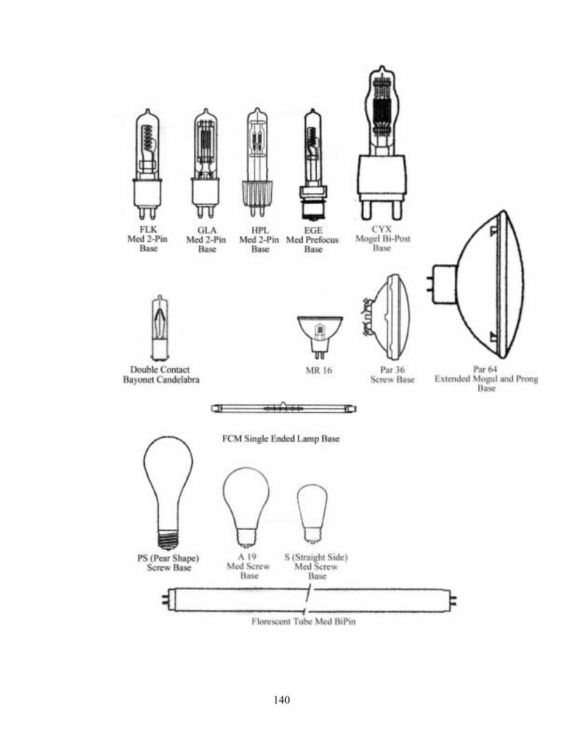
140
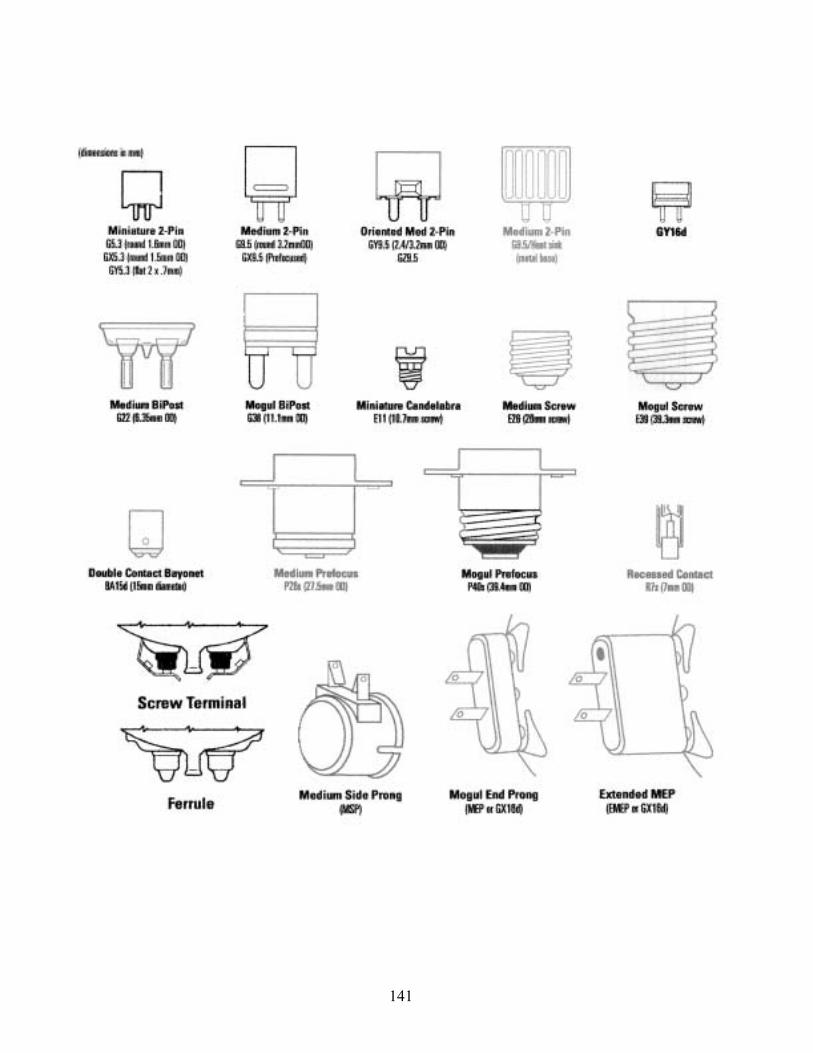
141
142
Arc lamp Sources
The usual general-purpose HID lamps are mercury vapor, metal halide and high-pressure sodium. You can purchase these at home centers, although usually only I wattages up to 400 watts. These versions of HID lamps are optimized for high efficiency, long life and to be inexpensive. However, the arc surface brightness of these lamps is roughly equal to the surface brightness of incandescent lamp filaments and general-purpose halogen lamp filaments. For our applications in spotlights, it is necessary to have a much more concentrated light source. This is where specialized HID lamps such as short arc lamps and HMI lamps come in. These types of Metal Halide lamps such as the MSR, MSD, CSI and HMI to name a few of the ones commonly used.
Short arc lamps consist of a roughly spherical quartz bulb with two heavy-duty electrodes spaced only a few millimeters apart at the tips. The bulb may contain xenon or mercury or both. Mercury short arc lamps have an argon gas fill for the arc to start in.
HMI lamps are metal halide lamps with a more compact and more intense arc. There are all sorts of HMI and similar lamps, including HTI lamps and the lamps used in HID auto headlights.
HTI lamps can be used beyond their rated lifetime, since a violent failure of the lamp is very unlikely. (This differs from HMI lamps, which should not be used beyond 25% of their rated lifetime.) Can use GS (gap shortened) technology to improve luminance by about 50 percent.
Cold start: Ignition takes a maximum of 1 second. Only a few kilovolts needed. After ignition, filler substances vaporize within 1 to 3 minutes. At the same time voltage, electrical output [stet], and luminous flux increase. Lamp current and color temperature start from a high level and fall.
Hot start: needs 20 kilovolts to more than 65 kilovolts.
HMI bulbs operate not with a filament but by striking and maintaining a DC plasma current between two electrodes. This is inherently more dangerous than AC current. The conversion to DC requires a ballast between the lamp and mains. The ballast must be earthed for safety reasons. All ballasts have an earth monitor lamp, and the lamp should not be operated if there is no earth detected. The wire wound ballasts have a permanent orange lamp that is a power to earth connection (either loss of earth or mains live will extinguish it). It must be noted this may trip some modern earth leakage detectors. Electronic ballasts usually have a momentary action earth detector switch/lamp.
Needs ballast to act as a current limiter.
Power Factor and Harmonic Current on the Neutral Wire Until relatively recently many electronic ballasts were made without power factor correction circuits. Because of its heavily capacitive front-end components, an electronic ballast puts current and voltage out of phase with one another. As a result, it typically has a power factor of 0.6 or less, meaning the ballast has to draw 40% more power than it uses. Associated with poor power factor are harmonic currents, which build up on the neutral wire. Sixty-five to 80% of the current does not cancel out between phases, even when all hot legs are evenly loaded. This means that when operating a large number of electronic ballasts, the neutral wire will need to be doubled or even tripled to carry the additive current Ballast Electronics Magnetic ballast is a very simple device. Input power is routed through the main breakers, which protect the circuit in the event of a short. From there power is routed to the transformer. The transformer provides the start-up charge for the igniter circuit, and then acts as a choke, regulating current to the lamp, once the
143
light is burning. Power from the transformer is routed to the main contactors (which are controlled by a low-voltage control circuit) and to the igniter circuit wire.
An electronic ballast on the other hand is quite a bit more complicated (Figure 2). Input current feeds through a full wave bridge rectifier, which inverts the negative half of the AC sine wave and makes it positive (the waveform looks like figure 1b at this point) then into a bank of capacitors which start to remove the 60 Hz rise and fall and flatten out the voltage-making it essentially DC. Current regulation is provided next, typically using a Field Effect Transistor (FET). At the final stage four specialized transistors (insulated gate bipolar transistors, or IGBTs) form a high-speed switching device, which turns the flat current into an alternating square wave. The frequency of the square wave is controlled by output control circuits attached to the ballasts little electronic cerebral cortex-the motherboard. The square wave frequency is not referenced to the line Hertz rate. This means electronic ballast will correct for a generator, which is slightly off speed. Through out the ballast, control and safety circuits run back to the motherboard. There are seven wires that run to the head. They are: two (thicker) power wires, VOH (voltage out hot) and VOR (voltage out return); a ground wire; the igniters power line; and three 15-volt logic signal wires: switch common (15V from ballast); On momentary (remote On switch at the head); and safe on (which is wired to the micro-switch in the lens door and to the Off switch on the head. Both switches must be closed for the main contactors in a magnetic ballast to close (in the case of an electronic ballast, the power modules act as an electronic circuit breaker).
In the head, VOR and VOH run directly to the terminals of the globe (Figure 3). The ground wire is connected to the lamp housing. The igniters power line and VOR are connected to the primary step-up transformer of the igniter circuit. This transformer steps voltage up to about 5000 volts. From there, current runs through a spark gap to a secondary transformer which boosts voltage up to the starting voltage of the lamp-in the order of 17kV.When the operator pushes the strike button two things happen: the contactors in the (magnetic) ballast are closed (in an electronic ballast the control board turns on the power control circuits-FETs and IGBTs-which applies voltage to VOR and VOH), and a 200V to 350V strike voltage is sent to the head on the igniter power line Taking it in extreme slow motion, the strike sequence happens as follows. The ignition voltage climbs from zero, increasing until the voltage potential is sufficient to bridge the spark gap. When a spark bridges the gap, a very high voltage start charge is delivered to the electrodes of the lamp from the secondary transformer. After 1 to 1.5 seconds a timer circuit removes igniter power from the circuit. Once the flow of electrons is initiated in the bulb, the ballast starts to hold back current. The lamp arc stabilizes and voltage rises to nor- mal operating value The spark gap is set to deliver the proper strike voltage for the bulb. To some extent increasing the spark gap can improve hot restrike characteristics, because it increases strike voltage, however adjusting the spark gap involves special tools and an experienced technician; the parts are fragile and extremely small. Too narrow a gap will pro duce insufficient voltage to arc the bulb; with too wide a gap, the voltage will not bridge the spark gap. The lamp is turned off when the SAFE ON line is interrupted-either by the lens door micro-switch or by the OFF button on the head or ballast. This opens the main contactors in magnetic ballast or shuts off the power control circuits in electronic ballast. Dimmers Lighting Equipment Safety Arc Lamp Sources HTI lamps can be used beyond their rated lifetime, since a violent failure of the lamp is very unlikely. (This differs from HMI lamps, which should not be used beyond 25% of their rated lifetime.) For safety reasons, HMI lamps should be replaced when operated more than 25 percent of their rated lifetime due to the risk of lamp explosion due to recrystallization of the quartz glass. Never bump, drop, apply excessive stress, or scratch the lamp. This could cause the lamp to burst! Do not operate any lamps with any traces of scratches, cracks, or physical damage.
144
Bulbs should not be touched by hand under any circumstances, else they will discolor, overheat and shatter. The gas in the bulbs is under low pressure when cold but very high pressure when hot. In use the bulbs are actually red hot, and potentially dangerous. The bulbs should be allowed to cool for 10 min. or so before attempting to open the lamp unit. Either the safety glass or full scrim should always be fitted if people are to be in front of the lights.
Xenon arc lamps
Xenon arc lamps could burst when not in operation causing serious injuries! It is critical to follow safety instructions when handling Xenon arc lamps
Xenon arc lamps have a high internal pressure. Depending upon the lamp, the internal pressure can exceed 10 ATM or 147 PSI, even when not in operation.
Always wear eye/face and body protection when handling Xenon arc lamps!
Never bump, drop, apply excessive stress, or scratch the lamp. This could cause the lamp to burst!
Always transport the lamp in the provided protective case or cover until installation!
Save the protective case or cover and packaging materials (box) for lamps that have been used to their rated service life. Use the protective case when disposing of the lamps.
Some Xenon arc lamps produce Ozone that is considered toxic at relatively high concentration levels. Use ozone-producing lamps in lamp housings equipped with exhaust systems.
Xenon arc lamps should not be used beyond their rated service life. Operation beyond the rated service life will cause the lamp to burst.
Xenon Arc Lamp Disposal
The following is Ushios recommendations for disposal of their lamps:
Wear a protective mask, leather gloves and protective clothing when handling a spent lamp.
Place the used lamp in its original protective case and original cardboard packaging (box) that was provided when the lamp was new.
Firmly attach tape around the original cardboard box to seal the lamp securely.
From approximately three (3) feet in height, drop the cardboard box, with the lamp and protective case inside, onto a hard floor to break the lamp.
Shake the cardboard box to determine if the lamp is broken.
During the course of working you will be called upon to make extension cords with plugging boxes at the end. When these boxes use parallel blade plugs or Edison plugs, it is important to only knock out the necessary holes in the duplex boxes. When a mistake is made for safety the hole should be filled with the appropriate metal plug.
145
Article 110.12b states: unused cable or raceway openings in boxes, raceways, auxiliary gutters, cabinets, cutout boxes, meter socket enclosures, equipment cases, or housings shall be effectively closed to afford protection substantially equivalent to the wall of the equipment. Where metallic plugs or plates are used with nonmetallic enclosures, they shall be recessed at least 6mm or (1/4) from the outer surface of the enclosure.
Hook-up Procedures Standard practice in the past when hooking up feeder tails to the disconnect lugs has been to simply tighten the lugs until they seem tight enough If one has the desire, than the National Electrical Code has specified torques for connecting wires to bus bars the following are two of those tables:
Article 110 Table 1.4 Torques for Recessed Allen head Screws.
Article 110 Table 1.5 Lug-Bolting Torques for Connections of Wire connectors to Busbars.
In most circumstances you will be called upon to hook-up a set of tails that have Cam Lock brand locking
connectors on one end and on the other bare ends. The tails, which are thought of as a set, will usually consist of five cables. Four of these cables are marked as following: black, red, blue for the hot phases and white as the neutral. The previous four cables for lighting power are usually 4/0 in size. In addition, the ground cable that is green or green with yellow stripes is the final cable in the set of five. When used with a load service of 4/0, the ground is sized no smaller 2/0. However on occasion when the loads are less than 200 amps, 2/0 will be used for the load phases, neutral cables and the ground or earth cable. The actual, routine for connecting the set of tails is as follows. But first a little ditty to remember: Green is ground the world round. What this means is, always hook-up the ground first to the ground bus bar in the disconnect box. After this the Neutral, to the neutral bus bar followed by the Red, Black, and Blue phases.
Bolt Diameter Tightening Torque (lb-ft) No. 8 or smaller 1.5
No. 10 2.0 ¼ in or less 6
5/16 in. 11 3/8 19 7/16 30
½ 40 9/16 or larger 55
Socket Size Across Flats (in.) Torque (lb-in)1/8 45 5/32 100 3/16 120 7/32 150
¼ 200 5/16 275 3/8 375 ½ 500
9/16 600
146
Above illustrates theoretical meter readings, and readings apply to the Green to Hot Phases as well. Also once the tails are bolted into the lugs, the feeder run out as a safety measure one should check that any disconnect switches within the portable system are turned off. Once you have established that they are the service should be energized with the road personal prior consent. At a convenient point within the system, all service disconnects that are energized should be metered for proper AC voltages. This should be done between the Ground/Green cable and neutral/White: a meter reading of 0 (zero) AC volts is what is desired here. Although you may find some voltage induced from other building services. The next check is between the Neutral/ White and the three phases/Red, Black and Blue. In a perfect world you will see something in the range of 110v to122v AC any thing over 125 you should check the service before allowing the balance of the loads to be energized! Assuming all voltages were correct, one should then do the same voltage check phase to ground. This will establish that you have a good system ground that you have connected into. Then finally phase to phase and this meter reading should be near 208v AC. Depending on load demands placed on the electrical service you will see variances from the above optimal meter readings. As a safety measure and as a precaution to the equipment that is being used the road/ equipment supervisor, crew chief, department head from the road show etc. Should always be involved with the initial hook-up, energization of equipment to assure them that the job is properly done. Above all ask if there is anything unusual that you need to be aware of! In some venues you will be required to use a disconnect panel that will require connectors that use a interlock that will prevent you from making the above connections out of order. It is not unusual for the house that you are working in, to have adapters that go from the interlocked connectors to standard cam-lock connectors. When it is time to disconnect the tails from the service disconnects on the wall for lighting, sound, carpentry motors etc. The order in which you hooked them up will be reversed so the Hot phases will be removed from the lugs first, neutral and then the ground. In this fashion a bonded equipment ground will exist in the system until the end in the event the feeder runs have not been disconnected from the tails. On very rare occasions you may be presented with a set of tails that deviate from the standard North American color code for power phasing and neutral. This will be as follows: Red, Black/ Hot-Phases, Yellow/ Hot-Phase and Blue as the Neutral. Now to recall the little ditty: Green is Ground The World Round. Green will still be ground. These bare-ended tails are the standard in England and Europe. When hooking up tails in the field you there may be the need to make use of delta power for lighting power and control. When you are in doubt of the power type that is going to be used meter between each phase/leg of power to ground to determine the voltages contained within the disconnect that is going to be used. If a high leg is encountered use a different disconnect if possible. It there are no other choices then
147
you will need to double up on the other two legs of power to obtain a phase to ground reading of 120 volts. According to the NEC, there should be a permanent marking of some sort, on the bus bar. The above is a minimum that should be done when doing the power hook-ups, and is a result of my experiences in doing a very routine job in a safe manner. Article 110.15 states: On a 4-wire, delta-connected system where the midpoint of one phase winding is grounded to supply lighting and similar loads, the conductor or busbar having the higher phase voltage to ground shall be durably and permanently marked by an outer finish that is orange in color or by other effective means. Such identification shall be placed at each point on the system where a connection is made if the grounded conductor is also present. In addition, while hooking up some types of power you may encounter the lack of a ground that is clearly marked in a green color that is typically ground. In these cases in some electrical systems, you will encounter a ground conductor that is marked using white or gray outer finish that may be applied as stripes on the conductor used as ground. In addition, while engaged in hooking up tails to service disconnects, busbars you may be required to find a place to connect a ground tail. This conductor that has been marked with green tape and typically has a green connector at the opposite end is usually terminated in the box. However, a mechanical connection may be used externally. This connection is typically made using an Allen lug at the end of the bare ended cable and the ring end of the lug being fastened to a lighting C-clamp. The C-clamp is then either fastened to the conduit that is carrying the building service into the service disconnect or a water pipe is used. When an external connection is necessary instead of the busbars, it is important to ensure that the point of connection has any non-conductive coating removed. In some circumstances, you may be required to hook-up tails to a generator. When doing so, it may be necessary to verify the grounds have been properly installed. This is an easy process, typically there have been more than one placed in the earth. Simply use a meter set on the Ohm scale and verify that there is 25 Ohms or less between the two ground electrodes in the ground. Follows are the two portions of the National Electrical Code that explains in greater detail the above paragraphs. If greater detail is necessary consult the NEC or Local codes for greater detail: Article 200.6b states: an insulated grounded conductor larger than 6 AWG shall be identified either by a continuous white or gray outer finish or by three continuous white stripes on other than green insulation along its entire length or at the time of installation by a distinctive white marking at its terminations. This marking shall encircle the conductor or insulation. Article 250.4 General Requirements for Grounding and Bonding, section A, and excerpts from section B. (A) Grounded Systems
(1) Electrical System Grounding. Electrical system that are grounded shall be connected to earth in a manner that will limit the voltage imposed by lightning, line surges or unintentional contact with higher-voltage lines and that will stabilize the voltage to earth during normal operation.
(2) Grounding of Electrical Equipment. Non-current carrying conductive materials enclosing electrical conductors or equipment, or forming part of such equipment, shall be connected to earth so as to limit the voltage to ground on these materials.
(3) Bonding of electrical Equipment. Non-current-carrying conductive materials enclosing electrical conductors or equipment or forming part of such equipment, shall be connected together and to the electrical supply source in a manner that establishes and effective ground-fault current path
(4) Bonding of Electrical Conductive Materials and Other Equipment. Electrically conductive materials that are likely to become energized shall be connected together and to the electrical supply source in a manner that establishes an effective ground-fault path.
(5) Effective Ground-Fault Path. Electrical equipment and wiring and other electrical conductive material likely to become energized shall be installed in a manner that creates a permanent, low-impedance circuit capable of safely carrying the maximum ground-fault current likely to be imposed on it from any point on the wiring supply source. The earth shall not be used as the sole equipment grounding conductor or effective ground-fault current path.
148
(B) Ungrounded Systems (4) Path for Fault Current. Electrical equipment, wiring, and other electrically conductive material
likely to become energized shall be installed in a manner that crates a permanent, low-impedance circuit from any point on the wiring system to the electrical supply source to facilitate the operation of over-current devices should a second fault occur on the wiring system. The earth shall not be used as the sole equipment grounding conductor or effective fault-current path.
Article 250.12 states: nonconductive coatings (such as paint, lacquer, and enamel) on equipment to be grounded shall be removed from threads and other contact surfaces to ensure good electrical continuity or be connected by means of fittings designed so as to make such removal unnecessary. Article 250.56 states: A single electrode consisting of a rod, pipe, or plate that does not have a resistance to ground of 25 Ohms or less shall be augmented by one additional electrode of any of the types specified by 250.52 (A)(2) through (A)(7). Where multiple rod, pipe or plate electrodes are installed to meet the requirements of this section, they shall not be less than 1.8 m (6 feet) apart. Lighting Rigging and Truss systems On-sight Lighting Techniques The work as a theatrical electrician should be performed in an efficient and neat manner why? Because the crew chief or client will want it redone if it is sloppy, which means that it may be unsafe or visually a mess to the clients intended audience. If for no other reason then the following article from the National Electrical Code (NEC 2002), which could adversely affect the ability of the show to go on. Article 110.12 mechanical Execution of Work
Electrical equipment shall be installed in a neat and workmanlike manner. The code continues to state the following:
The regulation in 110.12 calling for neat and workmanlike installations has appeared in the NEC as currently worded for more than half-century. It stands as a basis for pride in ones work and has been emphasized by persons involved in the training of apprentice electricians for many years. Many code conflicts or violations have been cited by the authority having jurisdiction based on the authoritys interpretation of neat and workmanlike Manner. Many electrical inspection authorities use their own experience or precedents in their local areas as the basis for their judgments. This would apply if a city inspector were to check our work and decided that in his judgment, the work is sloppy and constitutes a hazard. Practical skills
Learning Objectives/Outcomes Learn and practice skills taught in the previous sections to reinforce the knowledge gained and introduce apprentices to practical skills necessary to perform on the job training in a safe and expedient fashion. In certain environments it is advantages to be able to perform trouble shooting on various forms of equipment. Whether directly supervised by a client or road personnel whom you are working for. There
149
are various forms types to perform on electrical equipment you may be working on. These may range from a simple cross plugging of two adjoining loads to using a meter to check for various elements of electricity. When using a meter one may meter for a voltage being present using either the AC meter scale, or the DC meter scale. In our application it is typical that any loads that are connected to a dimmer or road rack are using AC current to supply voltage to the load. The DC meter scale is typically used to determine if voltage is present in battery-powered devices used on stage. The third most common meter scale used is the Ohm scale or continuity beeper tester found on most meters today. These scales are used to check for a continuous circuits or wiring pairs found in most of our jumper cables, multi-cables and the like. This test is to only be performed when the circuit is off or de-energized. Continuity Tests A wire conductor that is continuous without a break has a practical resistance of 0Ω. Thus, the ohmmeter can be used to test for continuity. This test should be conducted on the lowest ohms range. A break in the wire will give a reading of infinite resistance, indicating an open circuit. This type of test is useful if you are trying to locate a cable that may or may not have a lamp plugged into the end. If the multi-cable has a load on each circuit, then you will see 0Ω across all hot and neutral pairs or connectors. If one does not show 0Ω, then that will be the cable that has a burn out or no lamp plugged into the end. You may also use the same idea to perform a continuity test on a long run of cable by temporarily connecting a lamp to each cable and metering the cables one at a time with a meter to find each opposing end of the cable. Another method is to use a piece of wire to create a temporary short at each female cable end and run the same test. Once again only perform continuity test to a circuit that is off or de-energized. Cable and Loads In the course of setting up lighting systems you will be required to layout feeder cable and other load cables to lighting fixtures. Often times you will need to trust that the supervisor from the equipment supplier has done their homework. However, due to onsite job changes or from lack of doing a site survey they have found there are impediments to completing cabling of the different lighting loads that are placed. You will be called upon to cable the different lighting apparatuses, in order to bring power to them. Often times the dimmer locations planed and actual locations are the ones that change the most and require the longest runs. This were the next formula will come in handy if one has any question concerning safety of length of the run or if the dimmers/ lamps output seem to be not as bright as it should be. For three phase loads:
(18.7) x Load in Amps x distance is feet Cable size in circular mills
The following are some typical sizes that we work with: 4/0 = 211,600 circular mills 2/0 = 133,000 circular mills #2 = 66,360 circular mills
When one needs to calculate for a single-phase load, use 21.6 as the load factor in place of 18.7.
Dimmer Load Calculations Consideration also needs to be given when the lighting loads are plugged into the dimmers. One important consideration is to balance the loads/equipment being plugged. When one is using only one type of lighting fixture this is easily done because all dimmers are the same as seen in the previous example, contained in the electrical safety section. Once again determine a safe load in a three-phase system using the following formula:
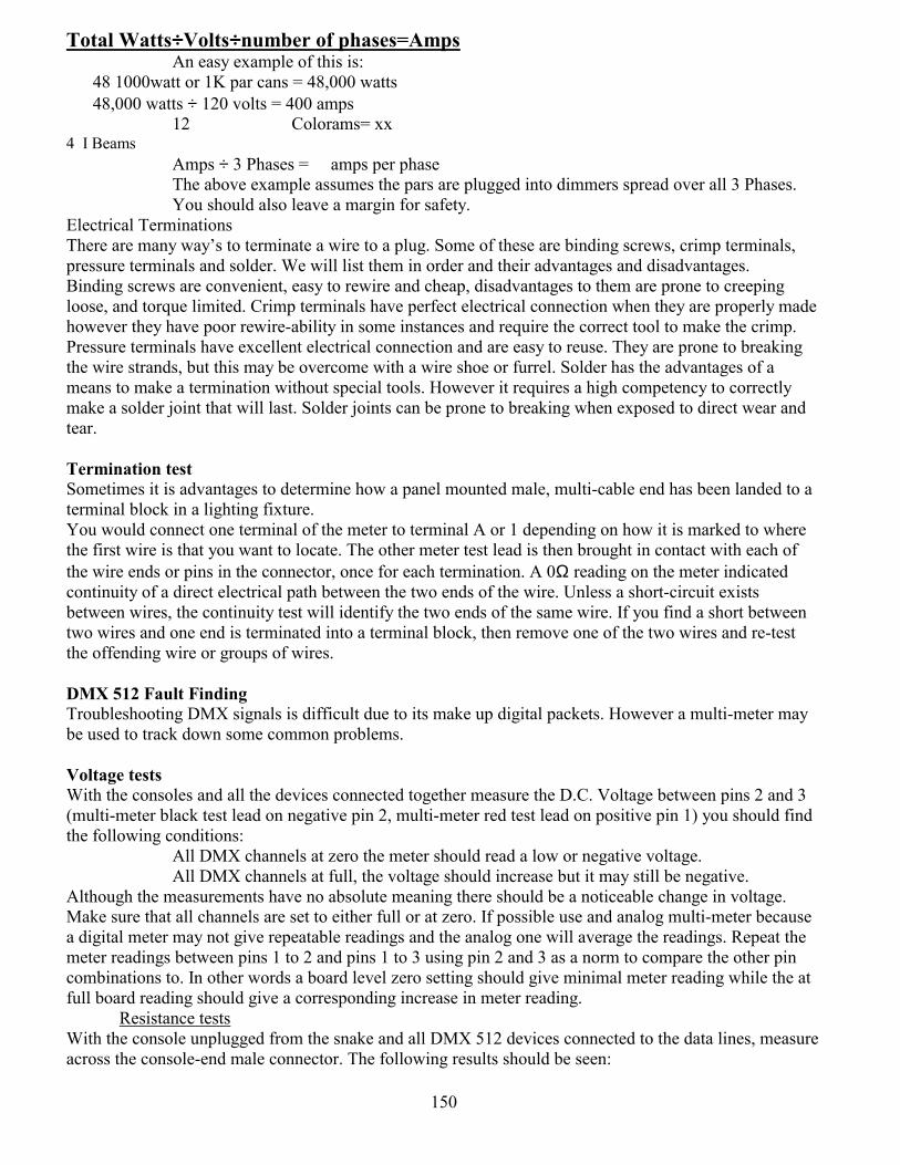
150
Total Watts÷÷÷÷Volts÷÷÷÷number of phases=Amps An easy example of this is:
48 1000watt or 1K par cans = 48,000 watts 48,000 watts ÷ 120 volts = 400 amps
12 Colorams= xx 4 I Beams
Amps ÷ 3 Phases = amps per phase The above example assumes the pars are plugged into dimmers spread over all 3 Phases. You should also leave a margin for safety.
Electrical Terminations There are many ways to terminate a wire to a plug. Some of these are binding screws, crimp terminals, pressure terminals and solder. We will list them in order and their advantages and disadvantages. Binding screws are convenient, easy to rewire and cheap, disadvantages to them are prone to creeping loose, and torque limited. Crimp terminals have perfect electrical connection when they are properly made however they have poor rewire-ability in some instances and require the correct tool to make the crimp. Pressure terminals have excellent electrical connection and are easy to reuse. They are prone to breaking the wire strands, but this may be overcome with a wire shoe or furrel. Solder has the advantages of a means to make a termination without special tools. However it requires a high competency to correctly make a solder joint that will last. Solder joints can be prone to breaking when exposed to direct wear and tear. Termination test Sometimes it is advantages to determine how a panel mounted male, multi-cable end has been landed to a terminal block in a lighting fixture. You would connect one terminal of the meter to terminal A or 1 depending on how it is marked to where the first wire is that you want to locate. The other meter test lead is then brought in contact with each of the wire ends or pins in the connector, once for each termination. A 0Ω reading on the meter indicated continuity of a direct electrical path between the two ends of the wire. Unless a short-circuit exists between wires, the continuity test will identify the two ends of the same wire. If you find a short between two wires and one end is terminated into a terminal block, then remove one of the two wires and re-test the offending wire or groups of wires. DMX 512 Fault Finding Troubleshooting DMX signals is difficult due to its make up digital packets. However a multi-meter may be used to track down some common problems. Voltage tests With the consoles and all the devices connected together measure the D.C. Voltage between pins 2 and 3 (multi-meter black test lead on negative pin 2, multi-meter red test lead on positive pin 1) you should find the following conditions:
All DMX channels at zero the meter should read a low or negative voltage. All DMX channels at full, the voltage should increase but it may still be negative.
Although the measurements have no absolute meaning there should be a noticeable change in voltage. Make sure that all channels are set to either full or at zero. If possible use and analog multi-meter because a digital meter may not give repeatable readings and the analog one will average the readings. Repeat the meter readings between pins 1 to 2 and pins 1 to 3 using pin 2 and 3 as a norm to compare the other pin combinations to. In other words a board level zero setting should give minimal meter reading while the at full board reading should give a corresponding increase in meter reading.
Resistance tests With the console unplugged from the snake and all DMX 512 devices connected to the data lines, measure across the console-end male connector. The following results should be seen:

151
Article 250.8 states: Grounding, conductors and bonding jumpers shall be connected by exothermic welding, listed pressure connectors, listed clamps, or other listed means. Connection devices or fitting that depend solely on solder shall not be used. Sheet mental screws shall not be used to connect grounding conductors to enclosures. Focusing Knots:
Bowline Clove Figure 8 Truckers Knot
152
256 128 64 32 16 8 4 2 1 Address0 0 0 0 0 0 0 0 0 51 0 0 0 0 0 0 0 0 0 52 0 0 0 0 0 0 0 0 0 53 0 0 0 0 0 0 0 0 0 54 0 0 0 0 0 0 0 0 0 55 0 0 0 0 0 0 0 0 0 56 0 0 0 0 0 0 0 0 0 57 0 0 0 0 0 0 0 0 0 58 0 0 0 0 0 0 0 0 0 59 0 0 0 0 0 0 0 0 0 60 0 0 0 0 0 0 0 0 0 61 0 0 0 0 0 0 0 0 0 62 0 0 0 0 0 0 0 0 0 63 0 0 0 0 0 0 0 0 0 64 0 0 0 0 0 0 0 0 0 65 0 0 0 0 0 0 0 0 0 66 0 0 0 0 0 0 0 0 0 67 0 0 0 0 0 0 0 0 0 68 0 0 0 0 0 0 0 0 0 69 0 0 0 0 0 0 0 0 0 70 0 0 0 0 0 0 0 0 0 71 0 0 0 0 0 0 0 0 0 72 0 0 0 0 0 0 0 0 0 73 0 0 0 0 0 0 0 0 0 74 0 0 0 0 0 0 0 0 0 75 0 0 0 0 0 0 0 0 0 76 0 0 0 0 0 0 0 0 0 77 0 0 0 0 0 0 0 0 0 78 0 0 0 0 0 0 0 0 0 79 0 0 0 0 0 0 0 0 0 80 0 0 0 0 0 0 0 0 0 81 0 0 0 0 0 0 0 0 0 82 0 0 0 0 0 0 0 0 0 83 0 0 0 0 0 0 0 0 0 84 0 0 0 0 0 0 0 0 0 85 0 0 0 0 0 0 0 0 0 86 0 0 0 0 0 0 0 0 0 87 0 0 0 0 0 0 0 0 0 88 0 0 0 0 0 0 0 0 0 89 0 0 0 0 0 0 0 0 0 90 0 0 0 0 0 0 0 0 0 91 0 0 0 0 0 0 0 0 0 92 0 0 0 0 0 0 0 0 0 93 0 0 0 0 0 0 0 0 0 94 0 0 0 0 0 0 0 0 0 95 0 0 0 0 0 0 0 0 0 96 0 0 0 0 0 0 0 0 0 97 0 0 0 0 0 0 0 0 0 98 0 0 0 0 0 0 0 0 0 99 0 0 0 0 0 0 0 0 0 100
256 128 64 32 16 8 4 2 1 Address0 0 0 0 0 0 0 0 0 1 0 0 0 0 0 0 0 0 0 2 0 0 0 0 0 0 0 0 0 3 0 0 0 0 0 0 0 0 0 4 0 0 0 0 0 0 0 0 0 5 0 0 0 0 0 0 0 0 0 6 0 0 0 0 0 0 0 0 0 7 0 0 0 0 0 0 0 0 0 8 0 0 0 0 0 0 0 0 0 9 0 0 0 0 0 0 0 0 0 10 0 0 0 0 0 0 0 0 0 11 0 0 0 0 0 0 0 0 0 12 0 0 0 0 0 0 0 0 0 13 0 0 0 0 0 0 0 0 0 14 0 0 0 0 0 0 0 0 0 15 0 0 0 0 0 0 0 0 0 16 0 0 0 0 0 0 0 0 0 17 0 0 0 0 0 0 0 0 0 18 0 0 0 0 0 0 0 0 0 19 0 0 0 0 0 0 0 0 0 20 0 0 0 0 0 0 0 0 0 21 0 0 0 0 0 0 0 0 0 22 0 0 0 0 0 0 0 0 0 23 0 0 0 0 0 0 0 0 0 24 0 0 0 0 0 0 0 0 0 25 0 0 0 0 0 0 0 0 0 26 0 0 0 0 0 0 0 0 0 27 0 0 0 0 0 0 0 0 0 28 0 0 0 0 0 0 0 0 0 29 0 0 0 0 0 0 0 0 0 30 0 0 0 0 0 0 0 0 0 31 0 0 0 0 0 0 0 0 0 32 0 0 0 0 0 0 0 0 0 33 0 0 0 0 0 0 0 0 0 34 0 0 0 0 0 0 0 0 0 35 0 0 0 0 0 0 0 0 0 36 0 0 0 0 0 0 0 0 0 37 0 0 0 0 0 0 0 0 0 38 0 0 0 0 0 0 0 0 0 39 0 0 0 0 0 0 0 0 0 40 0 0 0 0 0 0 0 0 0 41 0 0 0 0 0 0 0 0 0 42 0 0 0 0 0 0 0 0 0 43 0 0 0 0 0 0 0 0 0 44 0 0 0 0 0 0 0 0 0 45 0 0 0 0 0 0 0 0 0 46 0 0 0 0 0 0 0 0 0 47 0 0 0 0 0 0 0 0 0 48 0 0 0 0 0 0 0 0 0 49 0 0 0 0 0 0 0 0 0 50
153
256 128 64 32 16 8 4 2 1 Address0 0 0 0 0 0 0 0 0 101 0 0 0 0 0 0 0 0 0 102 0 0 0 0 0 0 0 0 0 103 0 0 0 0 0 0 0 0 0 104 0 0 0 0 0 0 0 0 0 105 0 0 0 0 0 0 0 0 0 106 0 0 0 0 0 0 0 0 0 107 0 0 0 0 0 0 0 0 0 108 0 0 0 0 0 0 0 0 0 109 0 0 0 0 0 0 0 0 0 110 0 0 0 0 0 0 0 0 0 111 0 0 0 0 0 0 0 0 0 112 0 0 0 0 0 0 0 0 0 113 0 0 0 0 0 0 0 0 0 114 0 0 0 0 0 0 0 0 0 115 0 0 0 0 0 0 0 0 0 116 0 0 0 0 0 0 0 0 0 117 0 0 0 0 0 0 0 0 0 118 0 0 0 0 0 0 0 0 0 119 0 0 0 0 0 0 0 0 0 120 0 0 0 0 0 0 0 0 0 121 0 0 0 0 0 0 0 0 0 122 0 0 0 0 0 0 0 0 0 123 0 0 0 0 0 0 0 0 0 124 0 0 0 0 0 0 0 0 0 125 0 0 0 0 0 0 0 0 0 126 0 0 0 0 0 0 0 0 0 127 0 0 0 0 0 0 0 0 0 128 0 0 0 0 0 0 0 0 0 129 0 0 0 0 0 0 0 0 0 130 0 0 0 0 0 0 0 0 0 131 0 0 0 0 0 0 0 0 0 132 0 0 0 0 0 0 0 0 0 133 0 0 0 0 0 0 0 0 0 134 0 0 0 0 0 0 0 0 0 135 0 0 0 0 0 0 0 0 0 136 0 0 0 0 0 0 0 0 0 137 0 0 0 0 0 0 0 0 0 138 0 0 0 0 0 0 0 0 0 139 0 0 0 0 0 0 0 0 0 140 0 0 0 0 0 0 0 0 0 141 0 0 0 0 0 0 0 0 0 142 0 0 0 0 0 0 0 0 0 143 0 0 0 0 0 0 0 0 0 144 0 0 0 0 0 0 0 0 0 145 0 0 0 0 0 0 0 0 0 146 0 0 0 0 0 0 0 0 0 147 0 0 0 0 0 0 0 0 0 148 0 0 0 0 0 0 0 0 0 149 0 0 0 0 0 0 0 0 0 150
256 128 64 32 16 8 4 2 1 Address0 0 0 0 0 0 0 0 0 151 0 0 0 0 0 0 0 0 0 152 0 0 0 0 0 0 0 0 0 153 0 0 0 0 0 0 0 0 0 154 0 0 0 0 0 0 0 0 0 155 0 0 0 0 0 0 0 0 0 156 0 0 0 0 0 0 0 0 0 157 0 0 0 0 0 0 0 0 0 158 0 0 0 0 0 0 0 0 0 159 0 0 0 0 0 0 0 0 0 160 0 0 0 0 0 0 0 0 0 161 0 0 0 0 0 0 0 0 0 162 0 0 0 0 0 0 0 0 0 163 0 0 0 0 0 0 0 0 0 164 0 0 0 0 0 0 0 0 0 165 0 0 0 0 0 0 0 0 0 166 0 0 0 0 0 0 0 0 0 167 0 0 0 0 0 0 0 0 0 168 0 0 0 0 0 0 0 0 0 169 0 0 0 0 0 0 0 0 0 170 0 0 0 0 0 0 0 0 0 171 0 0 0 0 0 0 0 0 0 172 0 0 0 0 0 0 0 0 0 173 0 0 0 0 0 0 0 0 0 174 0 0 0 0 0 0 0 0 0 175 0 0 0 0 0 0 0 0 0 176 0 0 0 0 0 0 0 0 0 177 0 0 0 0 0 0 0 0 0 178 0 0 0 0 0 0 0 0 0 179 0 0 0 0 0 0 0 0 0 180 0 0 0 0 0 0 0 0 0 181 0 0 0 0 0 0 0 0 0 182 0 0 0 0 0 0 0 0 0 183 0 0 0 0 0 0 0 0 0 184 0 0 0 0 0 0 0 0 0 185 0 0 0 0 0 0 0 0 0 186 0 0 0 0 0 0 0 0 0 187 0 0 0 0 0 0 0 0 0 188 0 0 0 0 0 0 0 0 0 189 0 0 0 0 0 0 0 0 0 190 0 0 0 0 0 0 0 0 0 191 0 0 0 0 0 0 0 0 0 192 0 0 0 0 0 0 0 0 0 193 0 0 0 0 0 0 0 0 0 194 0 0 0 0 0 0 0 0 0 195 0 0 0 0 0 0 0 0 0 196 0 0 0 0 0 0 0 0 0 197 0 0 0 0 0 0 0 0 0 198 0 0 0 0 0 0 0 0 0 199 0 0 0 0 0 0 0 0 0 200
154
256 128 64 32 16 8 4 2 1 Address0 0 0 0 0 0 0 0 0 201 0 0 0 0 0 0 0 0 0 202 0 0 0 0 0 0 0 0 0 203 0 0 0 0 0 0 0 0 0 204 0 0 0 0 0 0 0 0 0 205 0 0 0 0 0 0 0 0 0 206 0 0 0 0 0 0 0 0 0 207 0 0 0 0 0 0 0 0 0 208 0 0 0 0 0 0 0 0 0 209 0 0 0 0 0 0 0 0 0 210 0 0 0 0 0 0 0 0 0 211 0 0 0 0 0 0 0 0 0 212 0 0 0 0 0 0 0 0 0 213 0 0 0 0 0 0 0 0 0 214 0 0 0 0 0 0 0 0 0 215 0 0 0 0 0 0 0 0 0 216 0 0 0 0 0 0 0 0 0 217 0 0 0 0 0 0 0 0 0 218 0 0 0 0 0 0 0 0 0 219 0 0 0 0 0 0 0 0 0 220 0 0 0 0 0 0 0 0 0 221 0 0 0 0 0 0 0 0 0 222 0 0 0 0 0 0 0 0 0 223 0 0 0 0 0 0 0 0 0 224 0 0 0 0 0 0 0 0 0 225 0 0 0 0 0 0 0 0 0 226 0 0 0 0 0 0 0 0 0 227 0 0 0 0 0 0 0 0 0 228 0 0 0 0 0 0 0 0 0 229 0 0 0 0 0 0 0 0 0 230 0 0 0 0 0 0 0 0 0 231 0 0 0 0 0 0 0 0 0 232 0 0 0 0 0 0 0 0 0 233 0 0 0 0 0 0 0 0 0 234 0 0 0 0 0 0 0 0 0 235 0 0 0 0 0 0 0 0 0 236 0 0 0 0 0 0 0 0 0 237 0 0 0 0 0 0 0 0 0 238 0 0 0 0 0 0 0 0 0 239 0 0 0 0 0 0 0 0 0 240 0 0 0 0 0 0 0 0 0 241 0 0 0 0 0 0 0 0 0 242 0 0 0 0 0 0 0 0 0 243 0 0 0 0 0 0 0 0 0 244 0 0 0 0 0 0 0 0 0 245 0 0 0 0 0 0 0 0 0 246 0 0 0 0 0 0 0 0 0 247 0 0 0 0 0 0 0 0 0 248 0 0 0 0 0 0 0 0 0 49 0 0 0 0 0 0 0 0 0 250
256 128 64 32 16 8 4 2 1 Address0 0 0 0 0 0 0 0 0 251 0 0 0 0 0 0 0 0 0 252 0 0 0 0 0 0 0 0 0 253 0 0 0 0 0 0 0 0 0 254 0 0 0 0 0 0 0 0 0 255 0 0 0 0 0 0 0 0 0 256 0 0 0 0 0 0 0 0 0 257 0 0 0 0 0 0 0 0 0 258 0 0 0 0 0 0 0 0 0 259 0 0 0 0 0 0 0 0 0 260 0 0 0 0 0 0 0 0 0 261 0 0 0 0 0 0 0 0 0 262 0 0 0 0 0 0 0 0 0 263 0 0 0 0 0 0 0 0 0 264 0 0 0 0 0 0 0 0 0 265 0 0 0 0 0 0 0 0 0 266 0 0 0 0 0 0 0 0 0 267 0 0 0 0 0 0 0 0 0 268 0 0 0 0 0 0 0 0 0 269 0 0 0 0 0 0 0 0 0 270 0 0 0 0 0 0 0 0 0 271 0 0 0 0 0 0 0 0 0 272 0 0 0 0 0 0 0 0 0 273 0 0 0 0 0 0 0 0 0 274 0 0 0 0 0 0 0 0 0 275 0 0 0 0 0 0 0 0 0 276 0 0 0 0 0 0 0 0 0 277 0 0 0 0 0 0 0 0 0 278 0 0 0 0 0 0 0 0 0 279 0 0 0 0 0 0 0 0 0 280 0 0 0 0 0 0 0 0 0 281 0 0 0 0 0 0 0 0 0 282 0 0 0 0 0 0 0 0 0 283 0 0 0 0 0 0 0 0 0 284 0 0 0 0 0 0 0 0 0 285 0 0 0 0 0 0 0 0 0 286 0 0 0 0 0 0 0 0 0 287 0 0 0 0 0 0 0 0 0 288 0 0 0 0 0 0 0 0 0 289 0 0 0 0 0 0 0 0 0 290 0 0 0 0 0 0 0 0 0 291 0 0 0 0 0 0 0 0 0 292 0 0 0 0 0 0 0 0 0 293 0 0 0 0 0 0 0 0 0 294 0 0 0 0 0 0 0 0 0 295 0 0 0 0 0 0 0 0 0 296 0 0 0 0 0 0 0 0 0 297 0 0 0 0 0 0 0 0 0 298 0 0 0 0 0 0 0 0 0 299 0 0 0 0 0 0 0 0 0 300
155
256 128 64 32 16 8 4 2 1 Address0 0 0 0 0 0 0 0 0 301 0 0 0 0 0 0 0 0 0 302 0 0 0 0 0 0 0 0 0 303 0 0 0 0 0 0 0 0 0 304 0 0 0 0 0 0 0 0 0 305 0 0 0 0 0 0 0 0 0 306 0 0 0 0 0 0 0 0 0 307 0 0 0 0 0 0 0 0 0 308 0 0 0 0 0 0 0 0 0 309 0 0 0 0 0 0 0 0 0 310 0 0 0 0 0 0 0 0 0 311 0 0 0 0 0 0 0 0 0 312 0 0 0 0 0 0 0 0 0 313 0 0 0 0 0 0 0 0 0 314 0 0 0 0 0 0 0 0 0 315 0 0 0 0 0 0 0 0 0 316 0 0 0 0 0 0 0 0 0 317 0 0 0 0 0 0 0 0 0 318 0 0 0 0 0 0 0 0 0 319 0 0 0 0 0 0 0 0 0 320 0 0 0 0 0 0 0 0 0 321 0 0 0 0 0 0 0 0 0 322 0 0 0 0 0 0 0 0 0 323 0 0 0 0 0 0 0 0 0 324 0 0 0 0 0 0 0 0 0 325 0 0 0 0 0 0 0 0 0 326 0 0 0 0 0 0 0 0 0 327 0 0 0 0 0 0 0 0 0 328 0 0 0 0 0 0 0 0 0 329 0 0 0 0 0 0 0 0 0 330 0 0 0 0 0 0 0 0 0 331 0 0 0 0 0 0 0 0 0 332 0 0 0 0 0 0 0 0 0 333 0 0 0 0 0 0 0 0 0 334 0 0 0 0 0 0 0 0 0 335 0 0 0 0 0 0 0 0 0 336 0 0 0 0 0 0 0 0 0 337 0 0 0 0 0 0 0 0 0 338 0 0 0 0 0 0 0 0 0 339 0 0 0 0 0 0 0 0 0 340 0 0 0 0 0 0 0 0 0 341 0 0 0 0 0 0 0 0 0 342 0 0 0 0 0 0 0 0 0 343 0 0 0 0 0 0 0 0 0 344 0 0 0 0 0 0 0 0 0 345 0 0 0 0 0 0 0 0 0 346 0 0 0 0 0 0 0 0 0 347 0 0 0 0 0 0 0 0 0 348 0 0 0 0 0 0 0 0 0 349 0 0 0 0 0 0 0 0 0 350
256 128 64 32 16 8 4 2 1 Address0 0 0 0 0 0 0 0 0 351 0 0 0 0 0 0 0 0 0 352 0 0 0 0 0 0 0 0 0 353 0 0 0 0 0 0 0 0 0 354 0 0 0 0 0 0 0 0 0 355 0 0 0 0 0 0 0 0 0 356 0 0 0 0 0 0 0 0 0 357 0 0 0 0 0 0 0 0 0 358 0 0 0 0 0 0 0 0 0 359 0 0 0 0 0 0 0 0 0 360 0 0 0 0 0 0 0 0 0 361 0 0 0 0 0 0 0 0 0 362 0 0 0 0 0 0 0 0 0 363 0 0 0 0 0 0 0 0 0 364 0 0 0 0 0 0 0 0 0 365 0 0 0 0 0 0 0 0 0 366 0 0 0 0 0 0 0 0 0 367 0 0 0 0 0 0 0 0 0 368 0 0 0 0 0 0 0 0 0 369 0 0 0 0 0 0 0 0 0 370 0 0 0 0 0 0 0 0 0 371 0 0 0 0 0 0 0 0 0 372 0 0 0 0 0 0 0 0 0 373 0 0 0 0 0 0 0 0 0 374 0 0 0 0 0 0 0 0 0 375 0 0 0 0 0 0 0 0 0 376 0 0 0 0 0 0 0 0 0 377 0 0 0 0 0 0 0 0 0 378 0 0 0 0 0 0 0 0 0 379 0 0 0 0 0 0 0 0 0 380 0 0 0 0 0 0 0 0 0 381 0 0 0 0 0 0 0 0 0 382 0 0 0 0 0 0 0 0 0 383 0 0 0 0 0 0 0 0 0 384 0 0 0 0 0 0 0 0 0 385 0 0 0 0 0 0 0 0 0 386 0 0 0 0 0 0 0 0 0 387 0 0 0 0 0 0 0 0 0 388 0 0 0 0 0 0 0 0 0 389 0 0 0 0 0 0 0 0 0 390 0 0 0 0 0 0 0 0 0 391 0 0 0 0 0 0 0 0 0 392 0 0 0 0 0 0 0 0 0 393 0 0 0 0 0 0 0 0 0 394 0 0 0 0 0 0 0 0 0 395 0 0 0 0 0 0 0 0 0 396 0 0 0 0 0 0 0 0 0 397 0 0 0 0 0 0 0 0 0 398 0 0 0 0 0 0 0 0 0 399 0 0 0 0 0 0 0 0 0 400
156
256 128 64 32 16 8 4 2 1 Address0 0 0 0 0 0 0 0 0 456 0 0 0 0 0 0 0 0 0 457 0 0 0 0 0 0 0 0 0 458 0 0 0 0 0 0 0 0 0 459 0 0 0 0 0 0 0 0 0 460 0 0 0 0 0 0 0 0 0 461 0 0 0 0 0 0 0 0 0 462 0 0 0 0 0 0 0 0 0 463 0 0 0 0 0 0 0 0 0 464 0 0 0 0 0 0 0 0 0 465 0 0 0 0 0 0 0 0 0 466 0 0 0 0 0 0 0 0 0 467 0 0 0 0 0 0 0 0 0 468 0 0 0 0 0 0 0 0 0 469 0 0 0 0 0 0 0 0 0 470 0 0 0 0 0 0 0 0 0 471 0 0 0 0 0 0 0 0 0 472 0 0 0 0 0 0 0 0 0 473 0 0 0 0 0 0 0 0 0 474 0 0 0 0 0 0 0 0 0 475 0 0 0 0 0 0 0 0 0 476 0 0 0 0 0 0 0 0 0 477 0 0 0 0 0 0 0 0 0 478 0 0 0 0 0 0 0 0 0 479 0 0 0 0 0 0 0 0 0 480 0 0 0 0 0 0 0 0 0 481 0 0 0 0 0 0 0 0 0 482 0 0 0 0 0 0 0 0 0 483 0 0 0 0 0 0 0 0 0 484 0 0 0 0 0 0 0 0 0 485 0 0 0 0 0 0 0 0 0 486 0 0 0 0 0 0 0 0 0 487 0 0 0 0 0 0 0 0 0 488 0 0 0 0 0 0 0 0 0 489 0 0 0 0 0 0 0 0 0 490 0 0 0 0 0 0 0 0 0 491 0 0 0 0 0 0 0 0 0 492 0 0 0 0 0 0 0 0 0 493 0 0 0 0 0 0 0 0 0 494 0 0 0 0 0 0 0 0 0 495 0 0 0 0 0 0 0 0 0 496 0 0 0 0 0 0 0 0 0 497 0 0 0 0 0 0 0 0 0 498 0 0 0 0 0 0 0 0 0 499 0 0 0 0 0 0 0 0 0 500 0 0 0 0 0 0 0 0 0 501 0 0 0 0 0 0 0 0 0 502 0 0 0 0 0 0 0 0 0 503 0 0 0 0 0 0 0 0 0 504 0 0 0 0 0 0 0 0 0 505 506 507 508 509 510
256 128 64 32 16 8 4 2 1 Address0 0 0 0 0 0 0 0 0 401 0 0 0 0 0 0 0 0 0 402 0 0 0 0 0 0 0 0 0 403 0 0 0 0 0 0 0 0 0 404 0 0 0 0 0 0 0 0 0 405 0 0 0 0 0 0 0 0 0 406 0 0 0 0 0 0 0 0 0 407 0 0 0 0 0 0 0 0 0 408 0 0 0 0 0 0 0 0 0 409 0 0 0 0 0 0 0 0 0 410 0 0 0 0 0 0 0 0 0 411 0 0 0 0 0 0 0 0 0 412 0 0 0 0 0 0 0 0 0 413 0 0 0 0 0 0 0 0 0 414 0 0 0 0 0 0 0 0 0 415 0 0 0 0 0 0 0 0 0 416 0 0 0 0 0 0 0 0 0 417 0 0 0 0 0 0 0 0 0 418 0 0 0 0 0 0 0 0 0 419 0 0 0 0 0 0 0 0 0 420 0 0 0 0 0 0 0 0 0 421 0 0 0 0 0 0 0 0 0 422 0 0 0 0 0 0 0 0 0 423 0 0 0 0 0 0 0 0 0 424 0 0 0 0 0 0 0 0 0 425 0 0 0 0 0 0 0 0 0 426 0 0 0 0 0 0 0 0 0 427 0 0 0 0 0 0 0 0 0 428 0 0 0 0 0 0 0 0 0 429 0 0 0 0 0 0 0 0 0 430 0 0 0 0 0 0 0 0 0 431 0 0 0 0 0 0 0 0 0 432 0 0 0 0 0 0 0 0 0 433 0 0 0 0 0 0 0 0 0 434 0 0 0 0 0 0 0 0 0 435 0 0 0 0 0 0 0 0 0 436 0 0 0 0 0 0 0 0 0 437 0 0 0 0 0 0 0 0 0 438 0 0 0 0 0 0 0 0 0 439 0 0 0 0 0 0 0 0 0 440 0 0 0 0 0 0 0 0 0 441 0 0 0 0 0 0 0 0 0 442 0 0 0 0 0 0 0 0 0 443 0 0 0 0 0 0 0 0 0 444 0 0 0 0 0 0 0 0 0 445 0 0 0 0 0 0 0 0 0 446 0 0 0 0 0 0 0 0 0 447 0 0 0 0 0 0 0 0 0 448 0 0 0 0 0 0 0 0 0 449 0 0 0 0 0 0 0 0 0 450 451 452 452 453 454 455
157
Device Address Port 1 Port 2 Port 3 Port 4 Port 5 Port 6
Device
Address Port 1 Port 2 Port 3 Port 4 Port 5 Port 6
1 1 513 1025 1537 2049 2561 51 51 563 1075 1587 2099 2611 2 2 514 1026 1538 2050 2562 52 52 564 1076 1588 2100 2612 3 3 515 1027 1539 2051 2563 53 53 565 1077 1589 2101 2613 4 4 516 1028 1540 2052 2564 54 54 566 1078 1590 2102 2614 5 5 517 1029 1541 2053 2565 55 55 567 1079 1591 2103 2615 6 6 518 1030 1542 2054 2566 56 56 568 1080 1592 2104 2616 7 7 519 1031 1543 2055 2567 57 57 569 1081 1593 2105 2617 8 8 520 1032 1544 2056 2568 58 58 570 1082 1594 2106 2618 9 9 521 1033 1545 2057 2569 59 59 571 1083 1595 2107 2619
10 10 522 1034 1546 2058 2570 60 60 572 1084 1596 2108 2620 11 11 523 1035 1547 2059 2571 61 61 573 1085 1597 2109 2621 12 12 524 1036 1548 2060 2572 62 62 574 1086 1598 2110 2622 13 13 525 1037 1549 2061 2573 63 63 575 1087 1599 2111 2623 14 14 526 1038 1550 2062 2574 64 64 576 1088 1600 2112 2624 15 15 527 1039 1551 2063 2575 65 65 577 1089 1601 2113 2625 16 16 528 1040 1552 2064 2576 66 66 578 1090 1602 2114 2626 17 17 529 1041 1553 2065 2577 67 67 579 1091 1603 2115 2627 18 18 530 1042 1554 2066 2578 68 68 580 1092 1604 2116 2628 19 19 531 1043 1555 2067 2579 69 69 581 1093 1605 2117 2629 20 20 532 1044 1556 2068 2580 70 70 582 1094 1606 2118 2630 21 21 533 1045 1557 2069 2581 71 71 583 1095 1607 2119 2631 22 22 534 1046 1558 2070 2582 72 72 584 1096 1608 2120 2632 23 23 535 1047 1559 2071 2583 73 73 585 1097 1609 2121 2633 24 24 536 1048 1560 2072 2584 74 74 586 1098 1610 2122 2634 25 25 537 1049 1561 2073 2585 75 75 587 1099 1611 2123 2635 26 26 538 1050 1562 2074 2586 76 76 588 1100 1612 2124 2636 27 27 539 1051 1563 2075 2587 77 77 589 1101 1613 2125 2637 28 28 540 1052 1564 2076 2588 78 78 590 1102 1614 2126 2638 29 29 541 1053 1565 2077 2589 79 79 591 1103 1615 2127 2639 30 30 542 1054 1566 2078 2590 80 80 592 1104 1616 2128 2640 31 31 543 1055 1567 2079 2591 81 81 593 1105 1617 2129 2641 32 32 544 1056 1568 2080 2592 82 82 594 1106 1618 2130 2642 33 33 545 1057 1569 2081 2593 83 83 595 1107 1619 2131 2643 34 34 546 1058 1570 2082 2594 84 84 596 1108 1620 2132 2644 35 35 547 1059 1571 2083 2595 85 85 597 1109 1621 2133 2645 36 36 548 1060 1572 2084 2596 86 86 598 1110 1622 2134 2646 37 37 549 1061 1573 2085 2597 87 87 599 1111 1623 2135 2647 38 38 550 1062 1574 2086 2598 88 88 600 1112 1624 2136 2648 39 39 551 1063 1575 2087 2599 89 89 601 1113 1625 2137 2649 40 40 552 1064 1576 2088 2600 90 90 602 1114 1626 2138 2650 41 41 553 1065 1577 2089 2601 91 91 603 1115 1627 2139 2651 42 42 554 1066 1578 2090 2602 92 92 604 1116 1628 2140 2652 43 43 555 1067 1579 2091 2603 93 93 605 1117 1629 2141 2653 44 44 556 1068 1580 2092 2604 94 94 606 1118 1630 2142 2654 45 45 557 1069 1581 2093 2605 95 95 607 1119 1631 2143 2655 46 46 558 1070 1582 2094 2606 96 96 608 1120 1632 2144 2656 47 47 559 1071 1583 2095 2607 97 97 609 1121 1633 2145 2657 48 48 560 1072 1584 2096 2608 98 98 610 1122 1634 2146 2658 49 49 561 1073 1585 2097 2609 99 99 611 1123 1635 2147 2659 50 50 562 1074 1586 2098 2610 100 100 612 1124 1636 2148 2660
158
Device
Address Port 1 Port 2 Port 3 Port 4 Port 5 Port 6
Device Address Port 1 Port 2 Port 3 Port 4 Port 5 Port 6
101 101 613 1125 1637 2149 2661 151 151 663 1175 1687 2199 2711 102 102 614 1126 1638 2150 2662 152 152 664 1176 1688 2200 2712 103 103 615 1127 1639 2151 2663 153 153 665 1177 1689 2201 2713 104 104 616 1128 1640 2152 2664 154 154 666 1178 1690 2202 2714 105 105 617 1129 1641 2153 2665 155 155 667 1179 1691 2203 2715 106 106 618 1130 1642 2154 2666 156 156 668 1180 1692 2204 2716 107 107 619 1131 1643 2155 2667 157 157 669 1181 1693 2205 2717 108 108 620 1132 1644 2156 2668 158 158 670 1182 1694 2206 2718 109 109 621 1133 1645 2157 2669 159 159 671 1183 1695 2207 2719 110 110 622 1134 1646 2158 2670 160 160 672 1184 1696 2208 2720 111 111 623 1135 1647 2159 2671 161 161 673 1185 1697 2209 2721 112 112 624 1136 1648 2160 2672 162 162 674 1186 1698 2210 2722 113 113 625 1137 1649 2161 2673 163 163 675 1187 1699 2211 2723 114 114 626 1138 1650 2162 2674 164 164 676 1188 1700 2212 2724 115 115 627 1139 1651 2163 2675 165 165 677 1189 1701 2213 2725 116 116 628 1140 1652 2164 2676 166 166 678 1190 1702 2214 2726 117 117 629 1141 1653 2165 2677 167 167 679 1191 1703 2215 2727 118 118 630 1142 1654 2166 2678 168 168 680 1192 1704 2216 2728 119 119 631 1143 1655 2167 2679 169 169 681 1193 1705 2217 2729 120 120 632 1144 1656 2168 2680 170 170 682 1194 1706 2218 2730 121 121 633 1145 1657 2169 2681 171 171 683 1195 1707 2219 2731 122 122 634 1146 1658 2170 2682 172 172 684 1196 1708 2220 2732 123 123 635 1147 1659 2171 2683 173 173 685 1197 1709 2221 2733 124 124 636 1148 1660 2172 2684 174 174 686 1198 1710 2222 2734 125 125 637 1149 1661 2173 2685 175 175 687 1199 1711 2223 2735 126 126 638 1150 1662 2174 2686 176 176 688 1200 1712 2224 2736 127 127 639 1151 1663 2175 2687 177 177 689 1201 1713 2225 2737 128 128 640 1152 1664 2176 2688 178 178 690 1202 1714 2226 2738 129 129 641 1153 1665 2177 2689 179 179 691 1203 1715 2227 2739 130 130 642 1154 1666 2178 2690 180 180 692 1204 1716 2228 2740 131 131 643 1155 1667 2179 2691 181 181 693 1205 1717 2229 2741 132 132 644 1156 1668 2180 2692 182 182 694 1206 1718 2230 2742 133 133 645 1157 1669 2181 2693 183 183 695 1207 1719 2231 2743 134 134 646 1158 1670 2182 2694 184 184 696 1208 1720 2232 2744 135 135 647 1159 1671 2183 2695 185 185 697 1209 1721 2233 2745 136 136 648 1160 1672 2184 2696 186 186 698 1210 1722 2234 2746 137 137 649 1161 1673 2185 2697 187 187 699 1211 1723 2235 2747 138 138 650 1162 1674 2186 2698 188 188 700 1212 1724 2236 2748 139 139 651 1163 1675 2187 2699 189 189 701 1213 1725 2237 2749 140 140 652 1164 1676 2188 2700 190 190 702 1214 1726 2238 2750 141 141 653 1165 1677 2189 2701 191 191 703 1215 1727 2239 2751 142 142 654 1166 1678 2190 2702 192 192 704 1216 1728 2240 2752 143 143 655 1167 1679 2191 2703 193 193 705 1217 1729 2241 2753 144 144 656 1168 1680 2192 2704 194 194 706 1218 1730 2242 2754 145 145 657 1169 1681 2193 2705 195 195 707 1219 1731 2243 2755 146 146 658 1170 1682 2194 2706 196 196 708 1220 1732 2244 2756 147 147 659 1171 1683 2195 2707 197 197 709 1221 1733 2245 2757 148 148 660 1172 1684 2196 2708 198 198 710 1222 1734 2246 2758 149 149 661 1173 1685 2197 2709 199 199 711 1223 1735 2247 2759 150 150 662 1174 1686 2198 2710 200 200 712 1224 1736 2248 2760
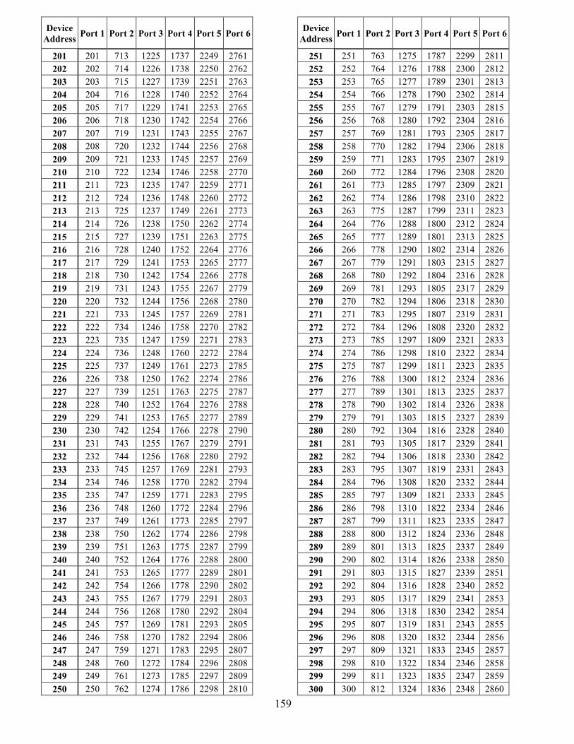
159
Device Address Port 1 Port 2 Port 3 Port 4 Port 5 Port 6
Device
Address Port 1 Port 2 Port 3 Port 4 Port 5 Port 6
201 201 713 1225 1737 2249 2761 251 251 763 1275 1787 2299 2811 202 202 714 1226 1738 2250 2762 252 252 764 1276 1788 2300 2812 203 203 715 1227 1739 2251 2763 253 253 765 1277 1789 2301 2813 204 204 716 1228 1740 2252 2764 254 254 766 1278 1790 2302 2814 205 205 717 1229 1741 2253 2765 255 255 767 1279 1791 2303 2815 206 206 718 1230 1742 2254 2766 256 256 768 1280 1792 2304 2816 207 207 719 1231 1743 2255 2767 257 257 769 1281 1793 2305 2817 208 208 720 1232 1744 2256 2768 258 258 770 1282 1794 2306 2818 209 209 721 1233 1745 2257 2769 259 259 771 1283 1795 2307 2819 210 210 722 1234 1746 2258 2770 260 260 772 1284 1796 2308 2820 211 211 723 1235 1747 2259 2771 261 261 773 1285 1797 2309 2821 212 212 724 1236 1748 2260 2772 262 262 774 1286 1798 2310 2822 213 213 725 1237 1749 2261 2773 263 263 775 1287 1799 2311 2823 214 214 726 1238 1750 2262 2774 264 264 776 1288 1800 2312 2824 215 215 727 1239 1751 2263 2775 265 265 777 1289 1801 2313 2825 216 216 728 1240 1752 2264 2776 266 266 778 1290 1802 2314 2826 217 217 729 1241 1753 2265 2777 267 267 779 1291 1803 2315 2827 218 218 730 1242 1754 2266 2778 268 268 780 1292 1804 2316 2828 219 219 731 1243 1755 2267 2779 269 269 781 1293 1805 2317 2829 220 220 732 1244 1756 2268 2780 270 270 782 1294 1806 2318 2830 221 221 733 1245 1757 2269 2781 271 271 783 1295 1807 2319 2831 222 222 734 1246 1758 2270 2782 272 272 784 1296 1808 2320 2832 223 223 735 1247 1759 2271 2783 273 273 785 1297 1809 2321 2833 224 224 736 1248 1760 2272 2784 274 274 786 1298 1810 2322 2834 225 225 737 1249 1761 2273 2785 275 275 787 1299 1811 2323 2835 226 226 738 1250 1762 2274 2786 276 276 788 1300 1812 2324 2836 227 227 739 1251 1763 2275 2787 277 277 789 1301 1813 2325 2837 228 228 740 1252 1764 2276 2788 278 278 790 1302 1814 2326 2838 229 229 741 1253 1765 2277 2789 279 279 791 1303 1815 2327 2839 230 230 742 1254 1766 2278 2790 280 280 792 1304 1816 2328 2840 231 231 743 1255 1767 2279 2791 281 281 793 1305 1817 2329 2841 232 232 744 1256 1768 2280 2792 282 282 794 1306 1818 2330 2842 233 233 745 1257 1769 2281 2793 283 283 795 1307 1819 2331 2843 234 234 746 1258 1770 2282 2794 284 284 796 1308 1820 2332 2844 235 235 747 1259 1771 2283 2795 285 285 797 1309 1821 2333 2845 236 236 748 1260 1772 2284 2796 286 286 798 1310 1822 2334 2846 237 237 749 1261 1773 2285 2797 287 287 799 1311 1823 2335 2847 238 238 750 1262 1774 2286 2798 288 288 800 1312 1824 2336 2848 239 239 751 1263 1775 2287 2799 289 289 801 1313 1825 2337 2849 240 240 752 1264 1776 2288 2800 290 290 802 1314 1826 2338 2850 241 241 753 1265 1777 2289 2801 291 291 803 1315 1827 2339 2851 242 242 754 1266 1778 2290 2802 292 292 804 1316 1828 2340 2852 243 243 755 1267 1779 2291 2803 293 293 805 1317 1829 2341 2853 244 244 756 1268 1780 2292 2804 294 294 806 1318 1830 2342 2854 245 245 757 1269 1781 2293 2805 295 295 807 1319 1831 2343 2855 246 246 758 1270 1782 2294 2806 296 296 808 1320 1832 2344 2856 247 247 759 1271 1783 2295 2807 297 297 809 1321 1833 2345 2857 248 248 760 1272 1784 2296 2808 298 298 810 1322 1834 2346 2858 249 249 761 1273 1785 2297 2809 299 299 811 1323 1835 2347 2859 250 250 762 1274 1786 2298 2810 300 300 812 1324 1836 2348 2860
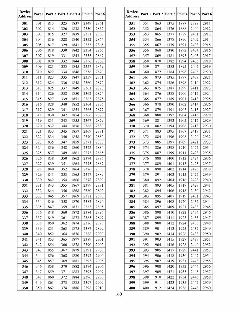
160
Device Address Port 1 Port 2 Port 3 Port 4 Port 5 Port 6
Device
Address Port 1 Port 2 Port 3 Port 4 Port 5 Port 6
301 301 813 1325 1837 2349 2861 351 351 863 1375 1887 2399 2911 302 302 814 1326 1838 2350 2862 352 352 864 1376 1888 2400 2912 303 303 815 1327 1839 2351 2863 353 353 865 1377 1889 2401 2913 304 304 816 1328 1840 2352 2864 354 354 866 1378 1890 2402 2914 305 305 817 1329 1841 2353 2865 355 355 867 1379 1891 2403 2915 306 306 818 1330 1842 2354 2866 356 356 868 1380 1892 2404 2916 307 307 819 1331 1843 2355 2867 357 357 869 1381 1893 2405 2917 308 308 820 1332 1844 2356 2868 358 358 870 1382 1894 2406 2918 309 309 821 1333 1845 2357 2869 359 359 871 1383 1895 2407 2919 310 310 822 1334 1846 2358 2870 360 360 872 1384 1896 2408 2920 311 311 823 1335 1847 2359 2871 361 361 873 1385 1897 2409 2921 312 312 824 1336 1848 2360 2872 362 362 874 1386 1898 2410 2922 313 313 825 1337 1849 2361 2873 363 363 875 1387 1899 2411 2923 314 314 826 1338 1850 2362 2874 364 364 876 1388 1900 2412 2924 315 315 827 1339 1851 2363 2875 365 365 877 1389 1901 2413 2925 316 316 828 1340 1852 2364 2876 366 366 878 1390 1902 2414 2926 317 317 829 1341 1853 2365 2877 367 367 879 1391 1903 2415 2927 318 318 830 1342 1854 2366 2878 368 368 880 1392 1904 2416 2928 319 319 831 1343 1855 2367 2879 369 369 881 1393 1905 2417 2929 320 320 832 1344 1856 2368 2880 370 370 882 1394 1906 2418 2930 321 321 833 1345 1857 2369 2881 371 371 883 1395 1907 2419 2931 322 322 834 1346 1858 2370 2882 372 372 884 1396 1908 2420 2932 323 323 835 1347 1859 2371 2883 373 373 885 1397 1909 2421 2933 324 324 836 1348 1860 2372 2884 374 374 886 1398 1910 2422 2934 325 325 837 1349 1861 2373 2885 375 375 887 1399 1911 2423 2935 326 326 838 1350 1862 2374 2886 376 376 888 1400 1912 2424 2936 327 327 839 1351 1863 2375 2887 377 377 889 1401 1913 2425 2937 328 328 840 1352 1864 2376 2888 378 378 890 1402 1914 2426 2938 329 329 841 1353 1865 2377 2889 379 379 891 1403 1915 2427 2939 330 330 842 1354 1866 2378 2890 380 380 892 1404 1916 2428 2940 331 331 843 1355 1867 2379 2891 381 381 893 1405 1917 2429 2941 332 332 844 1356 1868 2380 2892 382 382 894 1406 1918 2430 2942 333 333 845 1357 1869 2381 2893 383 383 895 1407 1919 2431 2943 334 334 846 1358 1870 2382 2894 384 384 896 1408 1920 2432 2944 335 335 847 1359 1871 2383 2895 385 385 897 1409 1921 2433 2945 336 336 848 1360 1872 2384 2896 386 386 898 1410 1922 2434 2946 337 337 849 1361 1873 2385 2897 387 387 899 1411 1923 2435 2947 338 338 850 1362 1874 2386 2898 388 388 900 1412 1924 2436 2948 339 339 851 1363 1875 2387 2899 389 389 901 1413 1925 2437 2949 340 340 852 1364 1876 2388 2900 390 390 902 1414 1926 2438 2950 341 341 853 1365 1877 2389 2901 391 391 903 1415 1927 2439 2951 342 342 854 1366 1878 2390 2902 392 392 904 1416 1928 2440 2952 343 343 855 1367 1879 2391 2903 393 393 905 1417 1929 2441 2953 344 344 856 1368 1880 2392 2904 394 394 906 1418 1930 2442 2954 345 345 857 1369 1881 2393 2905 395 395 907 1419 1931 2443 2955 346 346 858 1370 1882 2394 2906 396 396 908 1420 1932 2444 2956 347 347 859 1371 1883 2395 2907 397 397 909 1421 1933 2445 2957 348 348 860 1372 1884 2396 2908 398 398 910 1422 1934 2446 2958 349 349 861 1373 1885 2397 2909 399 399 911 1423 1935 2447 2959 350 350 862 1374 1886 2398 2910 400 400 912 1424 1936 2448 2960
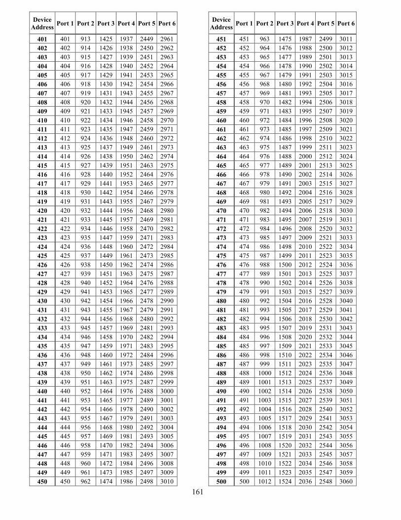
161
Device Address Port 1 Port 2 Port 3 Port 4 Port 5 Port 6
Device
Address Port 1 Port 2 Port 3 Port 4 Port 5 Port 6
401 401 913 1425 1937 2449 2961 451 451 963 1475 1987 2499 3011 402 402 914 1426 1938 2450 2962 452 452 964 1476 1988 2500 3012 403 403 915 1427 1939 2451 2963 453 453 965 1477 1989 2501 3013 404 404 916 1428 1940 2452 2964 454 454 966 1478 1990 2502 3014 405 405 917 1429 1941 2453 2965 455 455 967 1479 1991 2503 3015 406 406 918 1430 1942 2454 2966 456 456 968 1480 1992 2504 3016 407 407 919 1431 1943 2455 2967 457 457 969 1481 1993 2505 3017 408 408 920 1432 1944 2456 2968 458 458 970 1482 1994 2506 3018 409 409 921 1433 1945 2457 2969 459 459 971 1483 1995 2507 3019 410 410 922 1434 1946 2458 2970 460 460 972 1484 1996 2508 3020 411 411 923 1435 1947 2459 2971 461 461 973 1485 1997 2509 3021 412 412 924 1436 1948 2460 2972 462 462 974 1486 1998 2510 3022 413 413 925 1437 1949 2461 2973 463 463 975 1487 1999 2511 3023 414 414 926 1438 1950 2462 2974 464 464 976 1488 2000 2512 3024 415 415 927 1439 1951 2463 2975 465 465 977 1489 2001 2513 3025 416 416 928 1440 1952 2464 2976 466 466 978 1490 2002 2514 3026 417 417 929 1441 1953 2465 2977 467 467 979 1491 2003 2515 3027 418 418 930 1442 1954 2466 2978 468 468 980 1492 2004 2516 3028 419 419 931 1443 1955 2467 2979 469 469 981 1493 2005 2517 3029 420 420 932 1444 1956 2468 2980 470 470 982 1494 2006 2518 3030 421 421 933 1445 1957 2469 2981 471 471 983 1495 2007 2519 3031 422 422 934 1446 1958 2470 2982 472 472 984 1496 2008 2520 3032 423 423 935 1447 1959 2471 2983 473 473 985 1497 2009 2521 3033 424 424 936 1448 1960 2472 2984 474 474 986 1498 2010 2522 3034 425 425 937 1449 1961 2473 2985 475 475 987 1499 2011 2523 3035 426 426 938 1450 1962 2474 2986 476 476 988 1500 2012 2524 3036 427 427 939 1451 1963 2475 2987 477 477 989 1501 2013 2525 3037 428 428 940 1452 1964 2476 2988 478 478 990 1502 2014 2526 3038 429 429 941 1453 1965 2477 2989 479 479 991 1503 2015 2527 3039 430 430 942 1454 1966 2478 2990 480 480 992 1504 2016 2528 3040 431 431 943 1455 1967 2479 2991 481 481 993 1505 2017 2529 3041 432 432 944 1456 1968 2480 2992 482 482 994 1506 2018 2530 3042 433 433 945 1457 1969 2481 2993 483 483 995 1507 2019 2531 3043 434 434 946 1458 1970 2482 2994 484 484 996 1508 2020 2532 3044 435 435 947 1459 1971 2483 2995 485 485 997 1509 2021 2533 3045 436 436 948 1460 1972 2484 2996 486 486 998 1510 2022 2534 3046 437 437 949 1461 1973 2485 2997 487 487 999 1511 2023 2535 3047 438 438 950 1462 1974 2486 2998 488 488 1000 1512 2024 2536 3048 439 439 951 1463 1975 2487 2999 489 489 1001 1513 2025 2537 3049 440 440 952 1464 1976 2488 3000 490 490 1002 1514 2026 2538 3050 441 441 953 1465 1977 2489 3001 491 491 1003 1515 2027 2539 3051 442 442 954 1466 1978 2490 3002 492 492 1004 1516 2028 2540 3052 443 443 955 1467 1979 2491 3003 493 493 1005 1517 2029 2541 3053 444 444 956 1468 1980 2492 3004 494 494 1006 1518 2030 2542 3054 445 445 957 1469 1981 2493 3005 495 495 1007 1519 2031 2543 3055 446 446 958 1470 1982 2494 3006 496 496 1008 1520 2032 2544 3056 447 447 959 1471 1983 2495 3007 497 497 1009 1521 2033 2545 3057 448 448 960 1472 1984 2496 3008 498 498 1010 1522 2034 2546 3058 449 449 961 1473 1985 2497 3009 499 499 1011 1523 2035 2547 3059 450 450 962 1474 1986 2498 3010 500 500 1012 1524 2036 2548 3060
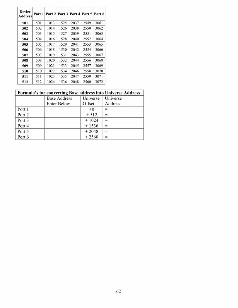
162
Device Address Port 1 Port 2 Port 3 Port 4 Port 5 Port 6
501 501 1013 1525 2037 2549 3061 502 502 1014 1526 2038 2550 3062 503 503 1015 1527 2039 2551 3063 504 504 1016 1528 2040 2552 3064 505 505 1017 1529 2041 2553 3065 506 506 1018 1530 2042 2554 3066 507 507 1019 1531 2043 2555 3067 508 508 1020 1532 2044 2556 3068 509 509 1021 1533 2045 2557 3069 510 510 1022 1534 2046 2558 3070 511 511 1023 1535 2047 2559 3071 512 512 1024 1536 2048 2560 3072
Formulas for converting Base address into Universe Address Base Address
Enter Below Universe Offset
Universe Address
Port 1 +0 = Port 2 + 512 = Port 3 + 1024 = Port 4 + 1536 = Port 5 + 2048 = Port 6 + 2560 =
163
Ohms Law Circle To use Ohms law circle place your finger over the value that you want to find E for voltage, I for current or R for resistance, and then the other tow will make up the formula. For example, if you place your finger over the E in the circle, the remainder of the circle will show I × R. If you then multiply the current times the resistance, you will find the value for the voltage. If, you would put your thumb over the finder, over the I, in the circle, and then the remainder of the circle will show E ÷ R. So, to find current we divide voltage by resistance. Lastly, if you place your finger over the R in the circle the remaining part of the circle shows E ÷ I.
Voltage = Current × Resistance or I × R = E Current = Voltage ÷ Resistance or E ÷ R = I Resistance = Voltage ÷ Current or E ÷ I = R
APPENDIX American Wire Gauge for Solid Copper conductors
Cross Sectional Area
Size AWG
Wire Diameter (inches)
Circular Mils
Square Inch
DC Resistance: Soft copper Max. resistance per 1000 FT at 20 C or )Ohms per 1000 FT)
4/0 0.4600 211,600 0.1662 0.04993 3/0 0.4096 167,800 0.1318 0.06296 2/0 0.3648 133,100 0.0145 0.07939 1/0 0.3249 105,400 0.08289 0.1001 1 0.2893 83,690 0.06573 0.1262 2 0.2576 66,379 0.05213 0.1592 3 0.2294 52,634 0.04134 0.2007 4 0.2043 41,472 0.03278 0.2531 6 0.1620 26,250 0.02062 0.4025 8 0.1285 16,510 0.01297 0.6400 10 0.1019 10,380 0.008155 1.018 12 0.08081 6530 0.005129 1.283 14 0.06408 4107 0.005225 2.573
164
The following are excerpts from the National Electrical Code 2002 table 400.4 is the source only cables that are Hard Usage and Extra Hard Usage have been extracted from that table. Lamp Cord has been included as an exemplary cable that is not Not Hard Usage, although it is used in the Theatrical Trade for varying purposes, such and Orchestra Pit Stand lights, which often carry a Underwriters Laboratory seal. If further referencing is necessary for suitability consult the Local and National code books to determine this. Do not strictly rely upon the section of the table included here as your one source of information. APPENDIX 400.4
Nominal Insulation Thickness Trade Name Type Letter
Voltage AWG or kcmil
Number of conductors
Insulation AWG or kcmil
mm mils Braid on Each Conductor
Outer Covering
Use
Lamp Cord C 300 600 18-16 14-10
2 or more Thermoset or thermoplastic
18-16 14-10
0.76 1.14
30 45 Cotton None Pendant or portable
Dry locations
NOT HARD USAGE
G 2000 12-500 2-6 plus grounding conductors
Thermoset 12-2 1-4/0 250-500
1.52 2.03 2.41
60 80 95
Oil resistant thermoset
Portable Power cable
G-GC 2000 12-500 3-6 plus grounding conductors and 1 ground check conductor
Thermoset 12-2 1-4/0 250-500
1.52 2.03 2.41
60 80 95
Oil resistant thermoset
Portable extra hard usage
Damp locations
Thermoset jacketed heater cord
HSJ 300 18-12 2, 3, or 4 Thermoset 18-16 0.76 30 None Cotton and Thermoset
Portable or portable heater Damp and
wet locations
Hard usage
Hard service cord
S See Note 4
600 18-12 2 or more Thermoset 18-16 14-10 8-2
0.76 1.14 1.52
30 45 60
None Pendant or portable
Damp locations
Extra hard usage
SC 600 Thermoset
SCE 600 Thermoplastic elastomer
Thermo-plastic elastomer
Flexible stage and lighting power cable
SCT 600
8-250 1 or more
Thermoplastic
8-2 1-4/0 250
1.52 2.03 2.41
60 80 90
Thermo-plastic
Portable extra hard usage
165
APPENDIX 400.4 cont.
Nominal Insulation Thickness
Trade Name Type Letter Voltage
AWG or kcmil
Number of conductors Insulation
AWG or kcmil mm mils
Braid on Each
ConductorOuter
Covering Use SE
See Note 4 600 Damp
locations SEW
See Note 4 See Note 13
600
Thermo-plastic elastomer
Damp and wet
locations
SEO See Note 4
600 Damp locations
SEOW See Note 4 See
Note 13 600
Thermoplastic elastomer
Damp and wet
locations
SEOO See Note 4
600 Oil resistant Damp locations
Hard service cord
SEOOW See Note 4 See
Note 13 600
18-2 2 or more
Thermoplastic elastomer
18-16 14-10
8-2
0.76 1.14 1.52
30 45 60
None
Oil resistant thermo-plastic
elastomer
Pendant or portable
Damp and wet
locations
Extra hard usage
SJ 300 Thermoset Thermoset Damp locations
SJE 300 Damp locations
SJEW See Note 13
300
Thermo-plastic elastomer
Damp and wet
locations
SJEO 300 Damp locations
SJEOW See Note 13
300
Thermo-plastic elastomer
Damp and wet
locations
SJEOO 300 Oil resistant thermo-plastic
elastomer
Damp locations
SJEOOW See Note 13
300
Oil resistant thermo-plastic
elastomer
Damp and wet
locations
Junior hard service cord
SJO 300
18-10 2-6
Thermoset
18-12 0.76 30 None
Oil resistant thermoset
Pendant or portable
Damp locations
Hard usage
166
Nominal Insulation Thickness
Trade Name Type Letter Voltage
AWG or kcmil
Number of conductors Insulation
AWG or kcmil mm mils
Braid on Each
ConductorOuter
Covering Use SJOW
See Note 13 300 Damp and
wet locations
SJOO 300 Damp locations
SJOOW See Note 13
300
Thermoset 18-12 0.76 30 Thermoset
Damp and wet
locations
SJT 300 Damp locations
SJTW See Note 13
300
10 1.14 45 Thermo-plastic
Damp and wet
locations
SJTO 300 Damp locations
SJTOW See Note 13
300
Thermoplastic
Damp and wet
locations
SJTOO 300 Damp locations
Junior hard service cord
SJTOOW See Note 13
300
18-10 2-6
Oil-resistant thermo-plastic
18-12 0.76 30
None
Oil-resistant thermo-plastic
Pendant or portable
Damp and wet
locations
Hard usage
SO See Note 4
600 Damp locations
SOW See Note 4 See
Note 13 600
Thermoset 18-16 0.76 30
Damp and wet
locations
SOO See Note 4
600 Damp locations
Hard Service Cord
SOOW See Note 4 See
Note 13 600
18-2 2 or more
Oil-resistant thermoset
14-10 8-2
1.14 1.52 45 60
Oil-resistant thermoset
Pendant or portable
Damp and wet
locations
Extra hard usage
167
APPENDIX 400.4 cont
Nominal Insulation Thickness
Trade Name Type Letter Voltage
AWG or kcmil
Number of conductors Insulation
AWG or kcmil mm mils
Braid on Each
ConductorOuter
Covering Use ST
See Note 4 600 Damp
locations STW
See Note 4 See Note 13
600
Thermo-plastic
Damp and wet
locations
Hard service cord
STO See Note 4
600
18-2 2 or more Thermoplastic 18-16 14-10
8-2
0.76 1.14 1.52
30 45 60
None
Oil-resistant thermo-plastic
Pendant or portable
Damp locations
Extra hard usage
Portable power cable
W 2000 12-500 501-1000
1-6 1 Thermoset 12-2 1-4/0
250-500 501-1000
1.52 2.03 2.41
2.80
60 80 95
110
Oil-resistant thermoset
Portable, extra hard usage
EV 600 18-500 See Note 11
18-16 14-10 8-2 1-
4/0 250-500
0.76(0.51) 1.14(0.76) 1.52(1.14) 2.03(1.52) 2.41(1.90)
30(20) 45(30) 60(45) 80(60)
95(75) See Note 12
Extra hard usage
EVJ 300 18-12 See Note 11
Thermoset elastomer with
optional nylon. See Note 12
18-12 0.76(0.51) 30(20) See Note 12
Thermoset
Hard usage
Electric vehicle cable
EVE 600 18-500 See Note 11
2 or more plus grounding conductor(s), plus optional hybrid data, signal communications, and optical fiber cables
Thermoplastic elastomer with
optional nylon. See Note 12
18-16 14-10 8-2 1-
4/0 250-500
0.76(0.51) 1.14(0.76) 1.52(1.14) 2.03(1.52) 2.41(1.90)
30(20) 45(30) 60(45) 80(60)
95(75) See Note 12
Optional
Thermo-plastic elastomer
Electric vehicle
charging
Wet locations
Extra hard usage
168
APPENDIX 400.4 cont.
Nominal Insulation Thickness
Trade Name Type Letter Voltage
AWG or kcmil
Number of conductors Insulation
AWG or kcmil mm mils
Braid on Each
ConductorOuter
Covering Use EVJE 300 18-12 See
Note 11 18-12 0.76(0.51) 30(20) See
Note 12 Thermo-plastic
elastomer Hard usage
EVT 600 18-500 See Note 11
18-16 14-10 8-2 1-
4/0 250-500
0.76(0.51) 1.14(0.76) 1.52(1.14) 2.03(1.52) 2.41(1.90)
30(20) 45(30) 60(45) 80(60)
95(75) See Note 12
Extra hard usage
Electric vehicle cable
EVJT 300 18-12 See Note 11
2 or more plus grounding conductor(s), plus optional hybrid data, signal communica-tions, and optical fiber cables
Thermoplastic elastomer with
optional nylon. See Note 12
18-12 0.76(0.51) 30(20) See Note 12
Optional
Thermo-plastic
Electric vehicle
charging
Wet locations
Hard usage
Note 4: Types G, G-GC S, SC, SCE, SCT, SE, SEO, SEOO, SO, SOO, ST, STO STOO, PPE and W shall be permitted for use on theatre stages, in garages and elsewhere flexible cords are permitted by this Code. Note 11: Conductor size for Types EV, EVJ, EVE, EVJE, EVT, and EVJT cable apply to nonpower-limited circuits only. Conductors of power-limited (data, signal, or communications) circuits may extend beyond the stated AWG size range. All conductors shall be insulated for the same cable voltage rating.
Note 13: Cords that comply with the requirements for outdoor cords and are so listed shall be permitted to be designated as weather and water resistant with the suffix W after the code type designation. Cords with the W suffix are suitable for use in wet locations.
In table 400.5 below, are the adjustment factors for more than three current-carrying conductors in a flexible cord or cable
Number of Conductors
Percent of Value in Tables 400.5(A) and (B)
4-6 80 7-9 70
10-20 50 21-30 45 31-40 40
41 and above 35
169
APPENDIX 400.5(A) Thermoset Types C, E, EO, PD, SJ, SJO, SJOW, SO, SOW, SP-1, SP-2, SP-3, SRD, SV,
SVO, SVOO
Size(AWG) Thermoplastic
Types TPT, TST
Thermoplastic Types ET,
ETLB, ETP, ETT, SE, SEW, SEO,
SEOW, SEOOW, SJE, SJEW, SJEO, SJEOW, SJEOOW, SJT, SJTW, SJTO, SJTOW, SJTOO, SJTOOW,SPE-1,
SPE-2, SPE-3, SPT-1, SPT-1W, SPT-2, SPT-2W
SPT-3, ST, SRDE, SRDT, STO,
STOW, STOO, STOOW, SVE, SVEO, SVT,
SVTO, SVTOO
Types HPD, HPN, HSJ,
HSJO, HSJOO A B
27 0.5 20 5** *** 18 7 10 10 17 12 13 16 10 13 15 15 17 14 15 18 20 12 20 25 30 10 25 30 35 8 35 40 6 45 55 4 60 70 2 80 95
APPENDIX Table 520.44 correction factors for
Multicable that has more than three current carrying conductors
Number of Conductors
Percent of usableAmpacity
4-6 80 7-24 70 25-42 60 43+ 50
170
Table 520.44 Ampacity of Extra Hard Usage when applied to a multiconductor with three current carrying conductors
APPENDIX 400.5(B)
60°C (140°F)
75°C (167°F)
90°C (194°F)
Size
AWG or kcmil D1 E2 F3 D1 E2 F3 D1 E2 F3
12 - 31 26 - 37 31 42 35 10 - 44 37 - 52 43 59 49 8 60 55 48 70 65 57 80 74 65 6 80 72 63 95 88 77 105 99 87 4 105 96 84 125 115 101 140 130 114 3 120 113 99 145 135 118 165 152 133 2 140 128 112 170 152 133 190 174 152 1 165 150 131 195 178 156 220 202 177
1/0 195 173 151 230 207 181 260 234 205 2/0 225 199 174 265 238 208 300 271 237 3/0 260 230 201 310 275 241 350 313 274 4/0 300 265 232 360 317 277 405 361 316 250 340 296 259 405 354 310 455 402 352 300 375 330 289 445 395 346 505 449 393 350 420 363 318 505 435 381 570 495 433 400 455 392 343 545 469 410 615 535 468 500 515 448 392 620 537 470 700 613 536 600 575 - - 690 - - 780 - - 700 630 - - 755 - - 855 - - 750 655 - - 785 - - 885 - - 800 680 - - 815 - - 920 - - 900 730 - - 870 - - 985 - - 1000 780 - - 935 - - 1055 - -
1. The ampacities under subheading D shall be permitted for single conductor types SC, SCE, SCT, PPE and W cable only where the individual conductors are not installed in raceways and are not in physical contact with each other except in lengths not to exceed 600mm (24 in) where passing through the wall of an enclosure.
2. The ampacities under subheading E apply to two-conductor cables and other multiconductor cables connected to utilization equipment so that only two-conductors are current carrying. 3. The ampacities under subheading F apply to three-conductor cables and other multiconductor cables connected to
utilization equipment so that only three-conductor are current carrying.
Temp. Rating of Cords & Cables
Maximum rating of Over-current protection
Size (AWG) 75°°°°C (167°°°°F) 90°°°°C (194°°°°F) Device (Breaker Size)
14 24 23 15 12 32 35 20 10 41 47 25 8 57 65 35 6 77 87 45 4 101 114 60 2 133 152 80
171
Lens Color Coding
Lamp Photometrics, Lamp Type and Weights Manufacture/ Name Fixture
Type True Field
Angle Beam Angle Lamp Weight
Altman Q 360 4.5 X 6.5 55° 22° GLC 575 13.5 Altman Q 360 6 X 9 37° 16° GLC 575 14 Altman Q 360 6 X 12 26° 11° GLC 575 15 Altman Q 360 6 X 16 19° 8.5° GLC 575 15 Altman Q 360 6 X 22 11° 8° GLC 575 15 Altman Shakespeare 50° 50° 23° GLC 575 15 Altman Shakespeare 40° 38° 20° GLC 575 15 Altman Shakespeare 30° 28° 13° GLC 575 15 Altman Shakespeare 20° 20° 13° GLC 575 15 Altman Shakespeare 12° 12° 7° GLC 575 21 Altman Shakespeare 10° 10° 7° GLC 575 16 Altman Shakespeare 5° 6.9° 5° GLC 575 16 Colortran 5/50 15° 15° 6.8° FLK 575 19.3 Colortran 5/50 20° 20° 8.3° FLK 575 19.7 Colortran 5/50 40° 40° 15° FLK 575 20.3 Colortran 5/50 50° 50° 17.5° FLK 575 20.9 Colortran 5/50 10° 10° 5.8° FLK 575 20.9 Colortran 5/50 5° 5° 3.3° FLK 575 30.1 ETC Source 4 19° 18° 15° HPL 575 14 ETC Source 4 26° 25° 17° HPL 575 14 ETC Source 4 36° 35° 25° HPL 575 14 ETC Source 4 50° 51° 33° HPL 575 14 ETC Source 4 10° 11° 9° HPL 575 15 ETC Source 4 5° 7° 6° HPL 575 19.2 Strand SL 19° - - GLC 575 15.0 Strand SL 26° - - GLC 575 15.0 Strand SL 36° - - GLC 575 15.0 Strand SL 50° - - GLC 575 15.0 Strand SL 10° - - GLC 575 15.0 Strand SL 5° - - GLC 575 17.6 Selecon Pacific 50° - - GLA 575 18.8 Selecon Pacific 40° - - GLA 575 18.8 Selecon Pacific 30° - - GLA 575 18.8
Beam Size Equivalent 6 X ETC Color Code PRG 19° 6 X 16 Red Red 26° 6 X 12 Black Blue 36° 6 X 9 None White 50° 4.5 X 6.5 Yellow Yellow 10° 6 X 22 Large Lens 5° None Really Large Lens

172
Selecon Pacific 20° - - GLA 575 18.8
173
ARTICLE 520 Theatres, Audience Areas of Motion Picture and Television
Studios, Performance Areas and Similar Locations
Contents I. General
520.1 Scope 520.2 Definitions 520.3 Motion Picture Projectors 520.4 Audio Signal Processing,
Amplification and Reproduction Equipment
520.5 Wiring Methods (A) General (B) Portable Equipment (C) Nonrated Construction
520.6 Number of Conductors in Raceway 520.7 Enclosing and Guarding Live Parts 520.8 Emergency Systems 520.9 Branch Circuits 520.10 Portable Equipment
II. Fixed Stage Switch Boards 520.21 Dead Front 520.22 Guarding Back of Switchboard 520.23 Control and Overcurrent Protection
of Receptacle Circuits 520.24 Metal Hood
520.25 Dimmers (A) Disconnection and Overcurrent
Protection (B) Resistance or Reactor-Type
Dimmers (C) Autotransformer-Type
Dimmers (D) Solid State Type Dimmers
520.26 Type of Switchboard (A) Manual (B) Remotely Controlled (C) Intermediate 520.27 Stage Switchboard Feeders (A) Type of Feeder (B) Neutral (C) Supply Capacity (D)
III. Fixed Stage Equipment Other Than Switchboards
520.41 Circuit Loads (A) Circuits Rated 20 Amperes or
Less (B) Circuits Rated Greater Than
20 Amperes 520.42 Conductor Insulation
520.43 Footlights (A) Metal Trough Construction (B) Other Than Metal Trough
Construction (C) Disappearing Footlights
520.44 Borders and Proscenium Sidelights (A) General (B) Cords and Cables for Border
Lights 520.45 Receptacles 520.46 Connector Strips, Drop Boxes,
Floor Pockets and Other Outlet Enclosures
520.47 Backstage Lamps (Bare Bulbs) 520.48 Curtain Machines 520.49 Smoke Ventilator Control
IV. Portable Switchboards on Stage 520.50 Road Show Connection Panel (A Type of Patch Panel)
(A) Load Circuits (B) Circuit Transfer (C) Overcurrent Protection (D) Enclosure 520.51 Supply
520.52 Overcurrent Protection 520.53 Construction and Feeders
(A) Enclosure (B) Energized Parts (C) ©Switch and Circuit Breakers (D) Circuit Breakers (E) Dimmers (F) Interior conductors (G) Pilot Light (H) Supply conductors (I) Cable Arrangement (J) Number of Supply
Interconnections (K) Single-Pole Separable
Connectors (L) Protection of Supply
Conductors and Connectors (M) Flanged Surface Inlets (N) Terminals (O) Neutral
174
(P) Qualified Personnel V. Portable Stage Equipment Other Than Switchboards
520.61 Arc Lamps 520.62 Portable Power Distribution Units
(A) Enclosure (B) Receptacles and Overcurrent
Protections (C) Busbars and Terminals (D) Flanged Surface Inlets (E) Cable Arrangement
520.63 Bracket Fixture Wiring (A) Bracket Wiring (B) Mounting
520.64 Portable Strips 520.65 Festoons 520.66 Special Effects 520.67 Multipole Branch Circuit
connectors 520.68 Conductors for Portables
(A) Conductor Type (B) Conductor Ampacity
520.69 Adapters (A) No Reduction in Current
Rating (B) Connectors (C) Conductor Types
VI. Dressing Rooms 520.71 Pendant Lamp holders 520.72 Lamp Guards 520.73 Switches Required
VII. Grounding 520.81 Grounding
I. General 520.1 Scope. This article covers all buildings or that part of a building or structure, indoor or outdoor, designed or used for presentation, dramatic, motion picture projection, or similar purpose and to specific seating areas within motion picture or television studios. The special requirements of Article 520 apply only to that part of a building used as a theatre or similar purpose and do not necessarily apply to the entire building. For example, the requirements of Article 520 would apply to an auditorium in a school building used for dramatic or other performances. The special requirements of this chapter apply to the stage, auditorium, dressing
rooms, and main corridors leading to the auditorium, but no to other parts of the building that are not involved in the use of the auditorium for performances or entertainment. The theatre space may be a traditional theatre, where the audience sits in the auditorium (house) facing the proscenium arch and view the performance on the stage on the other side of the arch, or other space, such as simple stage platform, either indoors or outdoors, with seats on three or four sides facing the platform. The audience areas of motion picture and television studios (as defined and covered in Article 530) are also covered by the requirement of Article 520. 520.2 Definitions Border Light. A permanently installed overhead strip light. Breakout Assembly. An adapter used to connect a multipole connector two or more branch circuits to multiple individual branch-circuit connectors. Bundle. Cables or conductors that are physically tied, wrapped, taped or otherwise periodically bound together. Connector strip. A metal wire-way containing pendant or flush receptacles. Drop Box. A box containing pendant or flush mounted receptacles attached to a multi-conductor cable via strain relief or multi-pole connector. Footlight. A Border light installed on or in the stage. Grouped. Cables or conductors positioned adjacent to one another but not in continuous contact with each other Performance Area. The stage and audience seating area associated with a temporary stage structure, whether indoors or outdoors, constructed of scaffolding, truss, platforms or similar devices that is used for the presentation of theatrical or musical productions or for public presentations. Portable Equipment. Equipment fed with portable cords or cable intended to be moved from one place to another. Portable Power Distribution Unit. A power distribution box containing receptacles and over-current devices.
175
Proscenium. The wall and arch that separates the stage from the auditorium. Stand Lamp (Work Light). A portable stand that contains a general purpose luminaries (lighting fixture) or lamp holder with guard for the purpose of providing general illumination on the stage or in the auditorium. Strip Light. A luminaire (lighting fixture) with multipole lamps arranged in a row Two-fer. An adapter cable containing one male plug and two female cord connectors used to connect two loads to one branch circuit. 520.3 Motion Picture Projectors. Motion Picture equipment and its installation and use shall comply with Article 540. 520.4 Audio Signal Processing, Amplification and Reproduction Equipment. Audio signal processing, amplification and reproduction equipment and its installation shall comply with Article 640. 520.5 Wiring Methods (A) General. The fixed wiring method shall be steal raceways, nonmetallic raceways encased in at least 50 mm (2 in.) of concrete, Type MI cable, MC cable, or AC cable containing an insulated equipment grounding conductor sized in accordance with Table 250.122 Exception: Fixed wiring methods shall be as provided in Article 640 for audio signal processing, amplification, and reproduction equipment, in Article 800 for communication control and signaling circuits, and in Article 760 for f ire alarm circuits. (B) Portable Equipment. The wiring for portable switchboards, stage set lighting, stage effects, and other wiring not fixed as to location shall be permitted with approved flexible cords and cable as provided elsewhere in Article 520. Fastening such cable and cords by uninsulated staples or nailing shall not be permitted. (C) Nonrated Construction. Nonmetallic-sheathed cable, Type AC cable, electrical nonmetallic tubing and rigid nonmetallic conduit shall b e permitted to be installed in those buildings or portions thereof that are not required to be of fire- rated construction by the applicable building code. Theatres and similar buildings are usually required to be of fire-rated construction, as determined by applicable building codes;
therefore, the fixed wiring methods are limited. See 518.4 for the requirements on wiring methods. The exception to the requirements for metal-enclosed or concrete-enclosed fixed wiring permits the installation of communications circuits, Class 2 and Class 3 remote-control and signaling circuit, sound reproduction wiring, and fire alarm circuits using wiring methods from the respective articles covering these systems in Chapters 7 and 8. Where portability, flexibility, and adjustments are necessary for portable switchboards, stage lighting, and special effects, suitable cords and cable are permitted. In accordance with 520.5 ©, Type cable, Type AC cable, ENT, and RNC are permitted as the wiring method in buildings or portions of buildings that are not required to be of fire-rated construction. In this application, Type AC cable is not required to contain an insulated equipment grounding conductor.
520.6 Number of Conductors in Raceway. The number of conductors permitted in any metal conduit, rigid nonmetallic conduit as permitted in this article, or electrical metallic tubing for border or stage pocket circuits or for remote-control conductors shall not exceed the percentage fill shown in Table 1 of Chapter 9. Where contained within an auxiliary gutter or a wireway, the sum of the cross-sectional areas of contained conductors at any cross-sectional areas of all contained conductors at any cross section shall not exceed 20 percent of the interior cross sectional area of the auxiliary gutter or wireway. The 30 conductor limitation of 366.6 and 376.22 shall not apply. 520.7 Enclosing and Guarding Live Parts. Live part shall be enclosed or guarded to prevent accidental contact by persons and objects. All switches shall be of the externally operable type. Dimmers, including rheostats, shall be placed in cases or cabinets that enclosed all live parts.
520.8 Emergency Systems. Control of emergency systems shall comply with Article 700. 520.9 Branch Circuits. A branch circuit on any size supplying one or more receptacles shall be permitted to supply stage set lighting. The voltage rating of the
176
receptacles shall not be less than the circuit voltage. Receptacle ampere ratings and branch-circuit conductor ampacity shall not be less than the branch-circuit overcurrent device ampere rating. Table 210.21 (B)(2) shall not apply. The stage lighting and associated equipment, such as stage effects, both fixed and portable, must be as flexible as possible. Connectors are often used for different purposes and are therefore marked on a show-by-show bases as to the voltage, current, and type of current actually employed. The provisions of 520.9 only require that connectors be rated sufficiently for the parameters involved, thus permitting connectors with voltage and current ratings lighter than the branch-circuit rating to be used. The intent of 520.9 is to exclude the occupancies referenced in Article 520 from all the general requirements relating to connector rating and branch-circuit loading found else where in the Code, such as Table 210.21 (B)(2). The requirements of 520.9 modify several other sections such as 210.23(C) and (D), which would disallow 40 ampere and larger branch circuits from serving 5000 watt and larger portable stage lighting equipment found in the theater. Stage set lighting is usually planned in advance, and the loads on each receptacle are known. Loads are not casually connected, as they might be at a typical general-use wall receptacle. Care is taken to ensure that circuits are not overloaded, thereby avoiding nuisance tripping during a performance.
520.10 Portable Equipment. Portable stage and studio lighting equipment and portable power distribution equipment shall be permitted for temporary use outdoors, provided the equipment is supervised by qualified personnel while energized and barriered from the general public. In accordance with 520.10, portable indoor stage or studio equipment that is not marked suitable for wet or damp locations is permitted to be used temporarily in outdoor locations. If rain occurs, this equipment is typically de-energized, and a protective cover is installed before it is re-energized. At the end of the day, this equipment is either de-energized and protected or dismantled and stored.
II Fixed Stage Switchboards
520.21 Dead Front. Stage switchboards shall be of the dead-front type and shall comply with Part IV or Article 384 unless approved based on suitability as stage switchboard as determined by a qualified testing laboratory and recognized test standards and principles. Early Stage switchboards were vertical marble or slate slabs mounted on the stage near the proscenium wall, with exposed knife switches and fuseholders mounted on them and with exposed resistance-type dimmer plates across the top. The dead front guarded back and metal hood requirements of the Code are intended to provide the operator with some sort of protection from shock, and the heat-producing equipment with some sort of protection from flammable curtains and scenery likely to be above and around the equipment. For these reasons, modern switchboards are totally enclosed.
520.22 Guarding Back of Switchboard. Stage switchboards having exposed live parts on the back of such boards shall be enclosed by the building walls, wire mesh grills, or by other approved methods. The entrance to this enclosure shall be by means of a self-closing door. 520.23 Control and Overcurrent Protection of Receptacle Circuits. Means shall be provided at a stage-lighting switchboard to which load circuits are connected for overcurrent protection of stage-lighting branch circuits, including branch circuits supplying stage and auditorium receptacles used for cord and plug connected stage equipment. Where the stage switchboard contains dimmers to control nonstage lighting, the location of the overcurrent protective devices for these branch circuits at the stage switchboard shall be permitted. The purpose of 520.23 is to ensure that the overcurrent protection devices are readily accessible to stage personnel during the presentation.
520.24 Metal Hood.
177
A stage switchboard that is not completely enclosed dead-front and dead-rear recessed into a wall shall be provided with a metal hood extending the full length of the board to protect all equipment of the board from falling objects. Because stages are usually crowded and a great deal of flammable material is often present, a stage switchboard is not permitted to have exposed live parts on its front. Moreover, the space at the rear of a stage switchboard must be guarded in order to prevent entrance or contact by unqualified and unauthorized persons. One acceptable method of accomplishing this is by enclosing the space between the rear of the switchboard and the wall in sheet-steel housing with a door at one end.
520.25 Dimmers. Dimmers shall comply with 520.25(A) through (D). (A) Disconnection and Overcurrent Protection.
Where dimmers are installed in ungrounded conductors, each dimmer shall have overcurrent protection not greater that 125 percent of the dimmer rating and shall be disconnected for all ungrounded conductors when the master or individual switch or circuit breaker supply such dimmer is in the open position.
A modern, high-density digital dimmer rack typically contains one dimmer (usually of 20-,
50-, or 100 ampere capacity) for each branch circuit connected to it. The rack is usually serviced by a 3-phase, 4-wire-plus-ground feeder, which is distributed via buses to all dimmers in the rack. Typical dimmer racks contain between 12 and 96 dimmers and may have total power capacities of up to 288 kW. In large theatrical system, many racks may be bused together. A central control electronics module drive multipole dimmers in the rack. A digital data link may connect the dimmer rack to the remotely located computer control console. Exhibit 520.2 shows a high-density digital SCR dimmer switchboard, and exhibit 520.3 shows its schematic diagram.
(B) Resistance- or Reactor- Type Dimmers. Resistance- or series reactor type dimmers shall be permitted to be places in either the grounded or the ungrounded conductor of the circuit. Where designed to open either the supply circuit to the dimmer to he circuit controlled by it, the dimmer shall then comply with 404.1. Resistance- or reactor-type dimmer placed in the grounded neutral conductor of the circuit shall not open the circuit. (C) Autotransformer-Type Dimmers. The circuit
supplying an autotransformer-type dimmer shall not exceed 150 volts between conductors. The grounded conductor shall be common to the input and output circuits. FPN: See 210.9 for circuits derived from autotransformers.
Circuits supplying autotransformer-type dimmers are not permitted to exceed 150 volts between conductors. Any desired voltage may be applied to the lamps, from full-line voltage to voltage so low that the lamps provide no illumination, by means of a movable contact tap. Typical connection for an autotransformer-type dimmer are shown in Exhibit 520.4. This type of dimmer produces very little heat and operates at high efficiency. Its dimming effect, within its maximum rating, is independent of the wattage of the load. Autotransformer-type dimmers are currently seldom used. See commentary that follows 470.4, which discusses saturable reactors that are sometimes used for stage dimmers.
(D) Solid-State-Type Dimmers. The circuit supplying a Solid-Statetype dimmer shall not exceed 150 volts between conductors unless the dimmer is listed specifically for higher voltage operation. Where a grounded conductor supplies a dimmer, it shall be common to the input and output circuits. Dimmer chassis shall be connected to the equipment grounding conductor.
Modern stage switchboards are usually of the remote-control type. The switchboard is operated from a remote console, typically a computer system such as the one shown in Exhibit 520.5. The switchboard or dimmer
178
rack is normally located offstage in a dimmer room, where proper climate control can be furnished and noise from the rack cooling fans will not interfere with the performance onstage. Branch circuits are usually connected to the dimmer rack on a dimmer per circuit basis. A digital control cable connects the computer and the dimmer rack, allowing the operator to be positioned or stage or in the auditorium for easy viewing of the performance.
A front view of a typical high-density digital SCR dimmer rack is shown in Exhibit 520.2. A schematic for this type of dimmer rack is shown in Exhibit 520.3. Dimmers for individual circuits are contained in dual plug-in dimmer modules. These modules also contain circuit breakers for overcurrent protection and filter chokes to eliminate acoustic noise from the lamp filaments. The digital control electronics are contained in a plug-in module with front-panel controls for configuration and testing.
520.26 Type of Switchboard. A stage switchboard shall be either one or a combination of the types specified in 520.26(A), (B), and (C). (A) Manuel. Dimmers and switches are operated by handles mechanically linked to the control devices. Manuel-type switchboard usually contain resistance-type or autotransformer-type dimmers. Exhibit 520.4 is a schematic of a manual autotransformer-type dimmer. (B) Remotely controlled. Devices are operated electrically from a pilot-type control console or panel. Pilot control panels either shall be part of the switchboard or shall be permitted to be at another location. (C) Intermediate. A stage switchboard with circuit interconnections is a secondary (patch panel) or panel board remote to the primary stage switchboard. It shall contain overcurrent protection. Where the required branch-circuit overcurrent protection is provided in the dimmer panel, it shall be permitted to be omitted from the intermediate switchboard.
An intermediate stage switchboard, usually called a patch panel, is located between the dimmer switchboard and the branch circuits. Its purpose is to either break down larger dimmer circuits to smaller branch circuits or to select branch circuits to be controlled by a dimmer, or both.
520.27 Stage Switchboard Feeders. (A) Type of Feeder. Feeders supplying stage
switchboards shall be one of the types in 520.27 (A)(1) through (A)(3).
(1) Single Feeder. A single feeder disconnected by a single disconnect device.
(2) Multiple Feeders to Intermediate Stage Switchboard (Patch Panel) Multiple feeders of unlimited quantity shall be permitted, provided that all multiple feeders are part of a single system. Where combined, neutral conductors in a given raceway shall be of sufficient ampacity to carry the maximum unbalanced current supplied by multiple feeder conductors in the same raceway, but they need not be greater than the ampacity of the neutral supplying the primary stage switchboard. Parallel neutral conductors shall comply with 310.4 The feeders to patch panels are often many dimmer-controlled circuits at 100 amperes or less, single phase, so they can be distributed to different combinations of the same size or smaller branch circuits. This type of installation usually requires a common neutral, and because of the quantity of circuits, many installations require several parallel neutral are sized as follows: 1. Size the common neutral to the feeder of the
primary switchboard. 2. Split this neutral into multipole parallel
conductors, one per raceway. 3. Equally divide, per phase, and size each
ungrounded conductor of the many single-phase circuits among the raceways.
In no case is it acceptable to install the ungrounded conductors in one raceway and the common neutral in another.
179
(3) Separate Feeder to Single Stage Switchboard (Dimmer Bank). Installations with separate feeders to a single primary stage switchboard shall have a disconnection means for each feeder. The primary stage switchboard shall have a permanent and obvious liable stating the number and location of disconnecting means. If the disconnection means are located in more than one distribution switchboard, the primary stage switchboard shall be provided with barriers to correspond with these multiple locations. Larger primary stage switchboards usually consist of several sections, often called dimmer racks, which form a dimmer bank. See Exhibit 520.2. These dimmer racks may be fed separately or be bused together to accept one or more feeder circuits. If an intermediate stage switchboard is connected to a primary stage switchboard, a single large feeder usually supplies the primary stage switchboard, because the intermediate stage switchboard patches only the ungrounded conductors and requires a common neutral. Modern theaters do not use intermediate stage switchboards, and dimmer banks may have one or several feeders. (B) Neutral. The neutral of feeders supplying solid-state, 3-phase, 4-wire dimming systems shall be considered a current-carrying conductor. © Supply capacity. For the purpose of computing supply capacity to switchboards, it shall be permissible to consider the maximum load that the switchboard is intended to control in a given installation, provided that the following apply:
(1) All feeders supplying the switchboard shall be protected by an overcurrent device with a rating not greater than the ampacity of the feeder.
(2) The opening of the overcurrent device shall not affect the proper operation of the egress or emergency lighting systems. FPN: For computation of stage feeder loads, see 220.10.
The feeder for single, primary stage switchboards is sized in accordance with the maximum load the switchboard is intended to control for a specific location. The feeder(s) must be protected by an overcurrent device that has a rating not greater
than the feeder ampacity. Operation of the overcurrent device is not allowed to have any effect on egress or emergency lighting system. The neutral of feeder supplying solid-state, 3-phase, 4-wire dimming systems will carry third-harmonic currents that are present even under balanced load conditions. III Fixed Stage Equipment Other Than Switchboards. 520.41 Circuit Loads.
(A) Circuits Rated 20 Amperes or Less. Footlights, border lights, and proscenium sidelights shall be arranged so that no branch circuit supplying such equipment carries a load exceeding 20 amperes. (B) Circuits Rated Greater Than 20 Amperes. Where heavy-duty Lampholders only are used, such circuits shall be permitted to comply with Article 210 for circuits supplying heavy-duty Lampholders.
In accordance with 210.23(B) and (C), 30-, 40-, or 50- ampere branch circuits are permitted if heavy-duty lampholders, such as medium- or mogul-base Edison screw shell types, are used for fixed lighting.
520.42 Conductor Insulation. Foot, border, proscenium, or portable strip lights and connector strips shall be wired with conductors that have insulation suitable for the temperature at which the conductors are operated, but not less than 125°C (257°F). The ampacity of the 125°C (257°F) conductors shall be that of 60°C (140°F) conductors. All drops from connector strips shall be 90°C (194°F) wire sized to the ampacity of 60°C (140°F) cords and cable with no more than 150mm (6 in.) of conductor extending into the connector strip. Section 310.15(B)(2)(a) shall not apply.
FPN: See Table 310.13 for conductor types.
The 125°C (257°F) minimum temperature rating is based on the heat from the lamp raising the ambient temperature in which the wiring is located. Drops from connector strips are usually flexible cord. Although the 90°C-
180
rated cord is also in the higher ambient, it is not in sufficient contact with other circuits that might also heat it. The derating factors of 310.15 (B)(2)(a) are judged unnecessary because the conductors are not all energized at one time, are not often energized at full intensity (dimmed), and are not energized continuously. 520.43 Footlights. (A) Metal Trough Construction. Where metal trough construction is employed for footlights, the trough containing the circuit conductors shall be made of sheet metal not lighter than 0.81 mm (0.032 in.) and treated to prevent oxidation. Lampholder terminals shall be kept at least 13 mm (1/2 in.) from the metal of the trough. The circuit conductors shall be soldered to the lampholder terminals. (B) Other Than-Metal Trough Construction. Where the metal t rough construction as specified in 520.43 is not used, footlights shall consist of individual outlets with Lampholders wired with rigid metal conduit, intermediate metal conduit, or flexible metal conduit, Type MC cable, or mineral-insulated, metal-sheathed cable. The circuit conductors shall be soldered to the lampholder terminals. (C) ©Disappearing Footlights. Disappearing footlights shall be arranged so that the current supply is automatically disconnected when the footlights are replaced in the storage recesses designed for them.
The footlights described in 520.43(A) and (B) are generally obsolete units that were built in the field. Modern footlights are compartmentalized, factory-wired assemblies for field installation, as shown in Exhibit 520.6. Footlight assemblies may be permanently exposed or be of the disappearing type. Disappearing footlights are arranged to automatically disconnect the current supply when the footlights are in the closed position, thereby preventing heat entrapment that could cause a fire. Disconnection is accomplished by mercury switches in the terminal compartment. 520.44 Borders and Proscenium Sidelights.
(A) General. Borders and proscenium sidelights shall be as follows:
(1) Constructed as specified in 520.43 (2) Suitably stayed and supported. (3) Designed so that the flanges of the reflectors or other adequate guards protect the lamps from mechanical damage and from accidental contact with scenery or other combustible material.
Exhibit 520.7 shows a modern border light installed over a stage. Exhibit 520.8 is a cross-sectional view that illustrates construction details. This particular border light is designed for 200-watt lamps. To obtain the highest illumination efficiency, each lamp is provided with its own reflector. Fitted to each reflector is a glass roundel available in any color. Commonly, Lampholders are wired alternately on three or four circuits. A splice box is provide on top of the housing for enclosing connections between the cable supplying the border light and the border lights internal wiring, which consists of wiring from the splice box to the lamp sockets in a trough extending the length of the border. (B) Cords and Cable for Border Lights. (1) General. Cords and cables for supply to border lights shall be listed for extra-hard usage. The cords and cables shall be suitably supported. Such cords and cables shall be employed only where flexible conductors are necessary. Ampacity of the conductors shall be as provided in 400.5 To facilitate height adjustment for cleaning and lamp replacement, border lights are usually supported by steel cables, as shown in Exhibit 520.9 Therefore, the circuit conductors supplying the border lights must be carried to the border light in a flexible cable. Each of these flexible cables usually contains many circuits; however, its overall size is limited by its ability to travel up and down without getting tangled. (2) Cords and Cables Not in Contact with Heat-Producing Equipment. Listed multiconductor extra-hard-usage-type cords and cables not in direct contact with equipment containing heat-producing elements shall be permitted to have their ampacity determined by Table 520.44. Maximum load current in any
181
conductor with an ampacity determined by table 520.44 shall not exceed the values in Table 520.44. The provisions of 520.44(B)(2) permit extra-hard usage cord no in direct contact with heat-producing equipment to have their ampacity determined by Table 520.44 instead of 400.5. Table 520.44 is based on a minimum 50 percent diversity factor. It includes the fact that not all circuits are on at the same time, not all circuits are at full intensity (dimmed), and not all circuits are on for a long period of time. If the load diversity does not follow this pattern, such as border lights that are all left on a full intensity to light the stage for rehearsal, lecture, or classroom purposes, this table must not be used. 520.45 Receptacles. Receptacles for electrical equipment on stages shall be rated in amperes. Conductors supplying receptacles shall be in accordance with Articles 310 and 400. 520.46 Connector Strips, Drop Boxes, Floor Pockets, and Other Outlet Enclosures. Receptacles for the connection of portable stage-lighting equipment shall be pendant or mounted in suitable pockets or enclosures and shall comply with 520.45. Supply cables for connector strips and drop boxes shall be as specified in 520.44(B). 520.47 Backstage Lamps (Bare Bulbs). Lamps (bare bulbs) installed in backstage and ancillary areas where they can come in contact with scenery shall be located and guarded so as to be free from physical damage and shall provide an air space of not less than 50mm (2 in.) between such lamps and any combustible material. Exception: Decorative lamps installed in scenery shall not be considered to be backstage lamps for the purpose or this section. 520.48 Curtain Machines. Curtain machines shall be listed. 520.49 Smoke Ventilator Control. Where stage smoke ventilators are released by an electrical device, the circuit operating the device shall be normally closed and shall be controlled by at lest two externally operable switches, one switch being placed at a readily accessible location on stage and the other where designated by the authority having jurisdiction. The device shall be designed for the full voltage of the circuit
to which it is connected, no resistance being inserted. The device shall be located in the loft above the scenery and shall be enclosed in a suitable metal box having a tight, self-closing door. In addition to the smoke ventilators being controlled from two externally operable switches at different location, the design of a normally closed circuit opens for any reason, such as a circuit breaker tripping or a fuse blowing. IV Portable Switchboards on Stage (A Type of Patch Panel) A panel designed to allow for road show connection of portable stage switchboards to fixed lighting outlets by means of permanently installed supplementary circuits. The panel, supplementary circuits, and outlets shall comply with 520.50(A) through (D). Also known as a road show interconnect or intercept panel, a road show connection panel is designed to connect the load side of a portable switchboard to the fixed building branch circuits and associated outlets. It may also provide for the fixed branch circuits to be connected to a fixed switchboard when the portable switchboard is not installed. (A) Load Circuits. Circuits shall terminate in grounding type polarized inlets of current and voltage rating that match the fixed-load receptacle. The grounding-type polarized inlets may be flush or pendant. The fixed-load receptacle is on the other end of the branch circuit that emanates from the panel. (B) Circuit Transfer. Circuits that are transferred between fixed and portable switchboards shall have all circuit conductors transferred simultaneously. In accordance with 520.50(B), simultaneous transfer of all conductors of the circuit, including any grounded conductor, is required. (C) Overcurrent Protection. The supply devices of these supplementary circuits shall be protected by branch-circuit overcurrent protective devices. The individual supplementary circuit, within the road show connection panel and theatre shall be protected by branch-circuit overcurrent protective
182
devices of suitable ampacity installed within the road show connection panel. The branch-circuit overcurrent protection should normally be in the switchboard but because some older units do not have this protection, backup overcurrent protection is provided by 520.50©. (D) Enclosure. Panel construction shall be in accordance with Article 408. 520.51 Supply. Portable switchboards shall be supplied only from power outlets of sufficient voltage and ampere rating. Such power outlets shall include only externally operable, enclosed fused switches or circuit breakers mounted on stage or at the permanent switchboard in locations readily accessible from the stage floor. Provisions for connection of an equipment grounding conductor shall be provided. The neutral of feeders supplying solid-state, 3-phase, 4-wire dimmer systems shall be considered a current-carrying conductor. Power outlets, known in the entertainment industry as company switches or bull switches, are the point in the wiring system where portable feeder cables connect to the fixed building wiring. They may be as simple as an overcurrent-protected multipole receptacle designed to accept the supply cable described in 520.53(P). Exception, or they may be multiple sets of parallel single-conductor feeder cables. These single-conductor feeder cables, as described in 520.53(H), may be terminated via single-pole separable connectors, as described in 520.53(K), or directly to Busbars, fused disconnect switches, or circuit breakers with wire connectors (lugs). 520.52 Overcurrent Protection. Circuits from portable switchboards directly supplying equipment containing incandescent lamps on not over 300 watts shall be protected by overcurrent protective devices having a rating or setting of not over 20 amperes. Circuits for Lampholders over 300 watts shall be permitted where overcurrent protection complies with Article 210.
520.53 Construction and Feeders. Portable switchboards and feeder for use on stages shall comply with 520.53(A) through (P). (A) Enclosure. Portable switchboards shall be placed within an enclosure of substantial construction, which shall be permitted to be arranged so that the enclosure is open during operation. Enclosures of wood shall be completely lined with sheet metal of not less than 0.51mm (0.020 in.) and shall be well galvanized, enameled, or otherwise properly coated to prevent corrosion or be of a corrosion resistant material. (B) Energized Parts. There shall not be exposed energized parts within the enclosure. (C) Switches and Circuit Breakers. All Switches and Circuit breakers shall be of the externally operable, enclosed type. (D) Circuit Protection. Overcurrent devices shall be provided in each ungrounded conductor of every circuit supplied through the switchboard. Enclosures shall be provided for all overcurrent devices in addition to the switchboard enclosure. (E) Dimmers. The terminals of dimmers shall be provided with enclosures, and dimmer faceplates shall be arranged so that accidental contact cannot be readily made with the faceplate contacts. (F) Interior Conductors. (1) Type. All conductors other than Busbars within the switchboard enclosure shall be stranded. Conductors shall be approved for an operating temperature at least equal to the approved operating temperature of the dimming devices used in the switchboard and in no case less than the following: (1) Resistance-type dimmers---200°C (392°F); or (2) Reactor-type, autotransformer, and solid-state dimmers--- 125°C (257°F). All control wiring shall comply with Article 725.
(2) Protection. Each conductor shall have an ampacity not less than the rating of the circuit breaker, switch, or fuse that it supplies. Circuit interrupting and bus bracing shall be in accordance with 110.9 and 110.10. The short-circuit current rating shall be marked on the switchboard.
183
Conductors shall be enclosed in metal wireways or shall be securely fastened in position and shall be bushed where they pass through metal. (G) Pilot Light. A pilot light shall be provided within the enclosure and shall be connected to the circuit supplying the board so that the opening of the master switch does not cut off the supply to the lamp. This lamp shall be on an individual branch circuit having overcurrent protection rated or set at not over 15 amperes. The requirements of 520.53(G) applies only to switchboards with a main disconnect, if provided, on the switchboard. The pilot light serves as a warning at the switchboard that indicated the presence of power before the main disconnect is activated. (H) Supply conductors. (1) General. The supply to a portable switchboard shall be by means of listed extra-hard usage cords or cables. The supply cords or cable shall terminate within the switchboard enclosure, in an external operable fused master switch or circuit breaker or in a connector assembly identified for the purpose. The supply cords or cable (and connector assembly) shall have sufficient ampacity to carry the total load connected to the switchboard and shall be protected by overcurrent devices. As with the supply end described in 520.51, the connection described in 520.53(H)(1) may be as simple as permanently terminated multiconductor supply cord or multipole connector assembly (inlet), or as complex as a set off parallel single conductor feeder cables. These cables may be field-connected to an assembly of single-pole connectors (inlet) or directly connected, with wire connectors, to busbars or a fused switch or breaker.
The requirements of 520.53(H)(1) permits road shows with fixed lighting plans to size the feeder to the actual connected load. (2) Single-Conductor Cables. Single-conductor portable supply cable sets shall not e smaller than 2 AWG conductors. The equipment grounding conductor shall not be smaller than 6 AWG conductor. Single-conductor grounded neutral cables for a supply shall be sized as per 520.53(O)(2). Where single conductors are
paralleled for increased ampacity, the paralleled conductors shall be of the same length and size. Single-conductor supply cables shall be grouped together but not bundled. The equipment grounding conductor shall be permitted to be of a different type, provided it meets the other requirements of this section, and it shall be permitted to be reduced in size as permitted by 250.122. Ground (neutral) and equipment grounding conductors shall be identified in accordance with 200.6, 250.119 and 310.12. Grounded conductors shall be permitted to be identified by marking at lest the firs 150mm (6 in.) from both ends of each length of conductor with white or gray. Equipment grounding conductors shall be permitted to be identified by marking at lest the firs 150mm (6 in.) from both ends of each length of conductor with green or green with yellow strips. Where more than one nominal voltage exists within the same premises, each ungrounded conductor shall be identified by system. (3) Supply Conductors Not Over 3.0m (10 ft) Long. Where supply conductors do not exceed 3.0m (10 ft) in length between supply and switchboard or supply and a subsequent overcurrent device, the supply conductors shall be permitted to be reduced in size where all of the following conditions are met: (1) The ampacity of the supply conductors shall be at least one-quarter of the ampacity of the supply overcurrent protection device. (2) The supply conductors shall terminate in a single over-current protection device that will limit the load to the ampacity of the supply conductors. This single overcurrent device shall be permitted to supply additional over-current devices on its load side. (3) The supply conductors shall not penetrate walls, floors, or ceilings or be run through doors or traffic areas. The supply conductors shall be adequately protected from physical damage. (4) The supply conductors shall be suitably terminated in an approved manner. (5) Conductors shall be continuous without splices or connectors. (6) Conductors shall not be bundled.
184
(7) Conductors shall be supported above the floor in an approved manner. (4) Supply conductors Not Over 6.0m (20 ft) Long. Where supply conductors do not exceed 6.0m (20 ft) in length between supply and a subsequent overcurrent protection device, the supply conductors shall be permitted to be reduced in size where all of the following conditions are met: (1) The ampacity of the conductors shall terminate in a single over-current protection device. (2) The supply conductors shall terminate in a single overcurrent protection device that limits the load to the ampacity of the supply conductors. This single overcurrent device shall be permitted to supply additional overcurrent devices on its load size. (3) The supply conductors shall not penetrate walls, floors, or ceilings or be run through doors or traffic areas. The supply conductors shall be adequately protected from physical damage. (4) The supply conductors shall be suitably terminated in an approved manner. (5) The supply conductors shall be supported in an approved manner at least 2.1m (7 ft) above the floor except at terminations. (6) Conductors shall not be bundled. (7) Tap conductors shall be in unbroken lengths. Loads of 144 kVA and greater are not uncommon, even on portable switchboard equipment. Installations in the field include lighting for theatrical-type productions with large numbers of stage lighting fixtures. However, only a fraction of the many fixtures installed are used at any one time. The intent of 530.53(H)(3) and (H)(4) is that the supply conductors must be sized according to their overcurrent protection and not by the total connected load. These requirements are similar to the requirements for taps found in 240.21. The tap rules of 530.53(H)(3) and (H)(4) are designed to allow one or more switchboards with small feeders to be connected to large supplies (company switches). If these rules are not complied with, proper overcurrent protection devices, either fixed or portable, must be provided for each of the smaller switchboards.
The requirement that the conductors not be bundled is so that column D of Table 400.5(B) can be employed. If the conductors are bundled, column F and all applicable derating factors would apply. Most devices used in the theatre to terminate single-conductor cables are rated for use at 90°C ampacity. However, if single-conductor cables are terminated directly to a circuit breaker or fused switch, a 75°C ampacity or lower would most likely apply. (5) Supply Conductors Not Reduced in Size. Supply conductors not reduced in size under provision 530.53(H)(3) and 530.53(H)(4) shall be permitted to pass through holes in wall specifically designed for the purpose. If penetration is through the fire-resistant-wall, it should be in accordance with 300.21. (I) Cable Arrangement. Cables shall be protected by bushings where they pass through enclosures and shall be arranged so that tension is not transmitted to the connections. Where power conductors pass through metal, the requirements of 300.20 shall apply. Tension on the connections is removed by using conventional strain relief devices, or often by lashing the cable to the enclosure with rope. (J) Number of supply Interconnections. Where connectors are used in a supply conductor, there shall be a maximum number of three interconnections (mated connector pairs) where the total length from supply to switchboard does not exceed 30m (100 ft), one additional interconnection shall be permitted for each additional 30m (100 ft) of supply conductor. The addition of excessive number of interconnections could jeopardize the mechanical and electrical integrity of the supply conductors. (K) Single-Pole Separable Connectors. Where single-pole portable cable connectors are used, they shall be listed and of the locking type. Sections 400.10, 406.6 and 406.7 shall not apply to listed single-pole separable connectors and single-conductor cable assemblies utilizing listed single-pole separable connectors. Where
185
paralleled sets of current-carrying, single-pole separable connectors are provided as input devices, they shall be prominently labeled with a warning indicating the presence of internal parallel connections. The use of single-pole separable connectors shall comply with at least one of the following conditions: (1) Connection and disconnection of connectors are only possible where the supply connectors are interlocked to the source and it is not possible to connect or disconnect connectors when the supply is energized. (2) Line connectors are of the listed sequential-interlocked type so that load connectors shall be connected in the following sequence:
a. Equipment grounding conductor connectors. b. Grounded circuit conductor connection, if
provided. c. Ungrounded conductor connector, and that
disconnection shall be in the reverse order. (3) A caution notice shall be provided adjacent to the line connectors indicating that plug connection shall be in the following order:
a. Equipment grounding conductor connectors. b. Grounded circuit conductor connection, if
provided. c. Ungrounded conductor connector, and that
disconnection shall be in the reverse order.
The requirements in 520.53(k) provide for a special type of connection device suitable for connecting single-conductor feeder cables. The connection device must b e listed and of the locking type, reducing the likelihood of its separating while under load. The connectors must be used in sets because they are only single-pole types. It is important that the grounding conductor be connected first and disconnected last, and that the grounded conductor be connected next to first and disconnected next-to-last. The connector sets must be arranged so as to reduce the likelihood that the connections will be made in the incorrect order, in accordance with one of the following methods. 1. Provide a scheme whereby the main
disconnect cannot be energized until all conductors are connected.
2. Provide a scheme whereby the connectors are precluded from being connected in any order than the proper one.
3. Provide a scheme whereby the individual connectors, free of any special electromechanical intervention, are marked with instructions to the user regarding proper connection.
Single-pole separable connectors are quick-connect feeder splicing and terminating devices, not attachment plugs or receptacles. They are designed to be sized, terminated, and inspected by a qualified person before being energized, and are to be guarded from accidental disconnection before being de- energized.
(L) Protection of Supply Conductors and Connectors. All supply conductors and connectors shall be protected against physical damage by an approved means. This protection shall not be required to be raceways. Rubber mats and commercially available rubber bridges are often used for the protection of supply conductors and connectors.
(M) Flanged Surface Inlets. Flanged surface inlets (recessed Plugs) that are used accept the power shall be rated in amperes.
(N) Terminals. Terminals to which stage cables are connected shall be located so as to permit convenient access to the terminals.
The requirement in 520.53(N) facilitates the field connection and disconnection of the large feeder cables as the show travels from place to place.
(O) Neutral.
(1) Neutral Terminal. In portable switchboard equipment designed for use with 3-phase, 4-wire with ground supply, the supply neutral terminal, its associated busbar, or equivalent wiring, or both, shall have an ampacity equal to at least twice the ampacity of the largest ungrounded supply terminal.
186
Exception: Where portable switchboard equipment is specifically constructed and identified to be internally converted in the field, in an approved manner, from use with a balanced 3-phase, 4-wire with ground supply to a balanced single-phase, 3-wire with ground supply, the supply neutral terminal and its associated busbar, equivalent wiring, or both, shall have an ampacity equal to at lest that of the larges ungrounded single-phase supply terminal.
The requirement in 520.53(O)(1) requires careful study because overlapping concepts are involved. If a 3-phase, 4-wireswitchboard of any kind is brought into a space that has only single-phase, 3-wire service, the switchboard will most likely be connected with two phases to one leg and one phase to the other. This connection could double the current flowing through neutral, so the neutral must be double size to allow for this possibility. The exception to 520.53(O)(1) provides for a smaller neutral sized for the single-phase feed where a switchboard contains switching devices that can divide the B-phase load equally between the A-phase and C-phase buses for single-phase operation.
Additionally, 3-phase, 4-wire switchboards that contain solid-state dimming devices must, when connected to a 3-phase, 4-wire supply, be connected to that supply with a multiconductor cable sized by counting the neutral as a current-carrying conductor, or with a set of single-conductor cables where the neutral is sized 130 percent greater than the phases. For example, a 3-phase, 4-wire switchboard containing six 50 ampere SCR dimmers (100 amperes per phase) without a reassignment switching system would have to have a 200-ampere neutral. (A single-phase, 3-wire-only switchboard would not have to meet this special requirement.) This 200 percent rule would cover all the components making up the neutral conductor system inside o r permanently attached to the switchboard, so as to allow for a full-size, single-phase, 3-wire feed when two of the 3-phase, 4-wire phase conductors are terminated to one single-phase, 3-wire leg. Note that the 200 percent neutral already covers the derating requirements (125 percent for a
multiconductor feeder system and 130 percent for a single-conductor feeder system) when used in the 3-phase mode. If a reassignment system were added, the neutral would be required to be only 150 amperes. Again, when used in the 3-phase mode, the derating factors would be covered. Note that the double-neutral requirement covers the terminal and associated busbar or wiring. This requirement covers the terminal and associated busbar wiring. This requirement begins at the main input terminals or busing, main input inlet connector, or attached main input cord-and-plug set and includes all wiring on the load side of that point. Power supply feeders easily detached a the terminals or inlet connector need not adhere to the 200 percent neutral rule because they can easily be sized on a show-by-show basis for the type of supply encountered. Theses cable must, however, adhere to the requirements of the neutral as a current-carrying conductor, or on the 130 percent single-conductors cable neutral. (2) Supply Neutral. The power supply conductors for portable switchboards shall be sized considering the neutral as a current-carrying conductor. Where single-conductor feeder cables, not installed in raceways, are used on multiphase circuits, the grounded neutral conductor shall have an ampacity of at lest 130 percent of the ungrounded circuit conductors feeding the portable switchboard. (P) Qualified Personnel. The routing of portable supply conductors, the making and breaking of supply conductors and other supply connection, and the energization and de-energization of supply services shall be performed by qualified personnel, and portable switchboards shall be so marked, indicating this requirement in a permanent and conspicuous manner. Exception: A portable switchboard shall be permitted to be connected to a permanently installed supply receptacle by other than qualified personnel, provided that the supply receptacle is protected for its rated ampacity by an overcurrent device of not greater than 150 amperes, and where the receptacle, interconnection and switchboard further
187
(a) Employ listed multipole connectors
suitable for the purpose for every supply interconnection, and
(b) Prevent access to all supply connections by the general public, and
(c) Employ listed extra-hard usage multiconductor cords or cables with an ampacity suitable for the type of load and not less than the ampere rating of the connectors.
The intent of 250.53(P) is to divide the acceptable practices in what are most likely to be professional and professional grade educational venues fro those in amateur or amateur grade educational venues. The basic requirements allow for such things as single-conductor feeder systems, feeders sized for the current-connected load, tap rules, and so on, and require the services of a qualified person. The exception to 250.53(P) provides for a conventional feeder system suitable for use by an untrained person. V Portable Stage Equipment Other Than Switchboards. 520.61 Arc Lamps. Arc lamps, including enclosed arc lamps and associated ballast, shall be listed. Interconnecting cord sets and interconnecting cords and cable shall be extra-hard usage type and listed. 520.62 Portable Power Distribution Units. Portable power distribution units shall comply with 520.62(A) through (E). (A) Enclosure. The construction shall be such that no current-carrying part will be exposed. (B) Receptacles and Overcurrent Protection. Receptacles shall comply with 520.45 and shall have branch-circuit overcurrent protection in the box. Fuses and circuit breakers shall be protected against physical damage. Cords or cables supplying pendant receptacles shall be listed for extra-hard usage.
(C) Busbars and Terminals. Busbars shall have an ampacity equal to the sum of the ampere ratings of all the circuits connected to the busbar. Lugs shall be provided for the connection of the master cable. (D) Flanged Surface Inlets. Flanged surface inlets (recessed plugs) that are used to accept the power shall be rated in amperes. (E) Cable Arrangement. Cables shall be adequately protected where they pass through enclosures and be arranged so that tension on the cable is not transmitted to the terminations. 520.63 Bracket Fixture Wiring. (A) Bracket Wiring. Brackets for use on scenery shall be wired internally, and the fixture stem shall be carried through to the back of the scenery where a bushing shall be placed on the end of the stem. Externally wired brackets or other fixtures shall be permitted where wired with cords designed for hard usage that extend through scenery and without joint or splice in canopy of fixture back and terminate in an approved-type stage connector located, where practical, with 450mm (18 in) of the fixture. (B) Mounting. Fixtures shall be securely fastened in place. 520.64 Portable Strips. Portable Strips shall be constructed in accordance with the requirements for border lights and proscenium sidelights in 520.44(A). The supply cable shall be protected by bushings where it passes through metal and shall be arranged so that tension on the cable will not be transmitted to the connections. FPN No 1: See 520.42 for wiring of portable strips FPN No 2: See 520.68(A)(3) for insulation types required on single conductors.

188
520.65 Festoons. Joints in festoon wiring shall be staggered. Lamps enclosed in lanterns or similar devices of combustible material shall be equipped with guards. Festoon lighting is defined in article 100. Joints in festoon wiring must be staggered and properly insulated. This arrangement ensures that connections will not be opposite one another, which could cause sparking due to improper insulation or unraveling of insulation, which, in turn, could ignite lanterns or other combustible material enclosing lamps. Where Lampholders have terminals of a type that puncture the conductor insulation and make contact with the conductors, stranded conductors should be used. 520.66 Special Effects. Electrical devices used for simulating lightning, waterfalls and the like shall be constructed and located so that flames, sparks, or hot particles cannot come in contact with combustible material. 520.67 Multipole Branch-Circuit Cable Connectors. Multipole branch-circuit cable connectors, male and female, for flexible conductors shall be constructed so that tension on the cord or cable is not transmitted to the connections. The female half shall be attached to the load end of the power supply cord or cable. The connector shall be rated in amperes and designed so that differently rated devices cannot be connected together; however, a 20 ampere T-slot receptacle shall be permitted to accept a 15 ampere attachment plug of the same voltage rating. Alternating-current multipole connectors shall be polarized and comply with 406.6 and 406.9.
FPN: See 400.10 for pull at terminals.
520.68 Conductors for Portables. (A) Conductor Type (1) General. Flexible conductors, including cable extensions, used to supply portable stage equipment shall be listed extra-hard usage cords or cables. (2) Stand Lamps. Reinforced cord shall be permitted to supply stand lamps where the cord is not subject to severe physical damage and is protected by an overcurrent device rated at not over 20 amperes. See 520.2 for the definition of stand lamp (work light). (B) High-Temperature Applications. A special assembly conductors in sleeving not longer than 1.0 m (3.3 ft) shall be permitted to be employed in lieu of flexible cord if the individual wires are stranded and rated not less than 125°C (67°F) and the outer sleeve is glass fiber with a wall thickness of at least 0.635mm (0.025 in). Portable stage equipment requiring flexible supply connections with a higher temperature rating where one end is permanently attached to the equipment shall be permitted and employ alternate, suitable conductors as determined by a qualified testing laboratory and recognized test standards. The requirements of 520.68(A)(3) cover the connection of high-temperature equipment including stage lighting fixtures, which often do operate at elevated temperatures. High-temperature (150°C to 250°C) extra-hard-usage cords limited to 3.3 ft in length to reduce the likelihood that they could be placed on the floor or other area where they might be damaged by traffic or moving scenery.
189
(4) Breakouts. Listed hard usage (junior hard service) cords shall be permitted in breakout assemblies where all of the following conditions are met: (1) The cords are utilized to connect between a
single multipole connector containing two or more branch circuits and multiple 2-pole, 3 wire connectors.
(2) The longest cord in the breakout assembly does not exceed 6.0m (20 ft).
(3) The breakout assembly is protected from physical damage by attachment over its entire length to a pipe or truss, tower, scaffold, or other substantial support structure.
(4) All branch circuits feeding the breakout assembly are protected overcurrent devices rated at not over 20 amperes.
The provision or 520.68(A)(4) applies to multiconductor cable assemblies with multipole connectors that contain more than one branch circuit. The breakout assembly is a multipole connector with several pendant receptacles connected to it, separating the multiple branch circuits into individual branch circuits. It is also possible to use a similar arrangement of pendant plugs to form a breaking assembly on the other end of the multiconductor cable. (B) Conductor Ampacity. The ampacity of conductors shall be as given in 400.5, except multiconductor, listed, extra-hard usage portable cords that are no in direct contact with equipment containing heat-producing elements shall be permitted to have their ampacity determined by Table 520.44. Maximum load current in any conductor with an ampacity determined by Table 520.44 shall not exceed the values in Table 520.44. In accordance with 520.68(B), portable, multicircuit, multiconductor cable is permitted to be sized accordance with Table 520.44, similar to the method used for border light cable. If portable, multicircuit, multiconductor cable is located horizontally directly above heat-producing equipment, I lieu of a connector strip, it should be spaced sufficiently above that equipment to avoid
the elevated temperatures or should be sized in accordance with 400.5. Exception: Where alternate conductors are allowed in 520.68(A)(3), their ampacity shall be as given in the appropriate table in the Code for the types of conductors employed. 520.69 Adapters. Adapters, two-fers and other single- and multiple-circuit outlet devices shall comply with 520.69(A), (B), and (C). (A) No reduction in Current Rating. Each receptacle and its corresponding cable shall have the same current and voltage rating as the plug supplying it. It shall not be utilized in a stage circuit with a greater rating. (B) Connectors. All connectors shall be wired in accordance with 520.67. Adapters are available where cords and connector bodies of one ampacity are connected to a plug of a larger rating. For example, a 12 AWG conductor with an ampacity of 20 amperes could be connected to a 100 ampere circuit. An overload could result in a fire because the circuit breaker or fuse would not provide adequate protection. The plug and receptacle must be of the same rating, in accordance with 520.69(B). (C) Conductor Type. Conductors for adapter and two-fers shall be listed, extra-hard usage or listed, hard usage (junior hard service) cord. Hard usage (junior hard service) cord shall be restricted in overall length to 1.0 m (3.3 ft).
190
VI Dressing Rooms 520.71 Pendant Lampholders. Pendant Lampholders shall not be installed in dressing rooms. 520.72 Lamp Guards. All exposed incandescent lamps in dressing rooms, where less than 2.5 m (8 ft) from the floor, shall be equipped with open-end guards riveted to the outlet box cover or otherwise sealed or locked in place. Because of the many types of flammable materials present in dressing rooms, such as costumes and wigs, pendant lampholders are not permitted. Lamps must be provided with suitable open-end guards that permit relamping and are not easily removed. This makes it difficult to circumvent the guards intended purpose of preventing contact between the lamps and flammable material. 520.73 Switches Required. All lights and any receptacle adjacent to the mirror(s) and above the dressing table counter(s) installed in dressing rooms shall be controlled by wall switches installed in the dressing room(s). Each switch controlling receptacles adjacent to the mirror(s) and above the dressing table counter(s) shall be provided with a pilot light located outside the dressing room, adjacent to the door to indicate when the receptacles are energized. Other outlets installed in the dressing room shall not be required to be switched. The requirement in 520.73 only addresses receptacles located adjacent to t he mirror and on the countertop. The receptacles located elsewhere in the room are not subject to the disconnect and pilot light requirements of 520.73. The purpose of the switching requirement is to make sure that all coffee pots, curling irons, hair dryers, and other similar countertops appliances can be readily disconnected at the end of the performance.
VII Grounding 520.81 Grounding. All metal raceways and metal-sheathed cables shall be grounded. The metal frames and enclosures of all equipment, including border lights and portable luminaries (lighting fixtures), shall be grounded. Grounding, where used, shall be in accordance with Article250.
191
City of Chicago Electrical Code
ARTICLE 520 ---Theatres, Audience Areas of Motion Picture and
Television Studios, Performance Areas and Similar Locations
Part A. General. 18-27-520.1 Scope. This article covers all buildings or that part of
a building or structure designed or used for presentation, dramatic, musical, motion picture projection, or similar purposes and to specific audience seating areas within motion picture or television studios.
18-27-520.2 Definitions.
Border Light. A permanently installed overhead strip light
Bundled. Cables or conductors that are physically tied, wrapped, taped or otherwise periodically bound together.
Breakout Assembly. An adapter used to
connect a multiple connector containing two or more branch circuits to multiple individual branch circuit connectors.
Connector Strip. A metal wireway
containing pendant or flush receptacles. Drop Box. A box containing pendant- or
flush-mounted receptacles attached to a multiconductor cable via strain relief, or a multipole connector.
Footlight. A border light installed on or in the
stage. Grouped. Cables or conductors positioned
adjacent to one another but not in continuous contact with each other.
Portable Equipment. Equipment fed with
portable cords or cables intended to be moved from one place to another.
Portable Power Distribution Unit. Apower distribution box containing receptacles and overcurrent devices
Proscenium. The wall and arch that separates
the stage from the auditorium (house). Stand Lamp (Work Light). A portable
stand that contains a general-purpose lighting fixture or lamp holder with guard for the purpose of providing general illumination on the stage or in the auditorium.
Strip Light. A lighting fixture with multiple
lamps arranged in a row. Two-Fer. An adapter cable containing one
male plug and tow female cord connectors used to connect two loads to one branch circuit.
18-27-520.3. Motion Picture Projectors.
Motion picture equipment and its installation and use shall comply with Article 540.
18-27-520.4. Audio Signal Processing, Amplification, and reproduction Equipment.
Audio signal processing, amplification, and reproduction equipment and its installation shall comply with Article 640.
18-27-520.5. Wiring Methods. (a) General. The f fixed wiring method shall
be metal raceways, and type MI cable. (Reference use only type MI: Type MI mineral-insulation, metal sheathed cable is a listed factory assembly of one or more conductors insulated with a highly compressed refractory mineral insulation and enclosed in a liquid tight and gastight continuous copper or alloy steel sheath.)
Exception: Fixed wiring methods shall be as provided in Article 640 for signal processing, amplification and reproduction, in Article 800 for communications circuits, in Article 725 for Class 2 and Class 3 remote control and signaling circuits, and in Article 760 for fire alarm circuits.
192
(b) Portable Equipment. The wiring for portable switchboards, stage set lighting, stage effects, and other approved flexible cords and cables as provided elsewhere in Article 520. Fastening such cables and cords by uninsulated staples or nailing shall not be permitted. 18-27-520.6. Number of conductors in Raceway. The number of conductors permitted in any metal conduit, or electrical metallic tubing for border or stage pocket circuits or for remote-control conductors shall not exceed the percentage fill shown in Table 1 of Article 900. Where contained within an auxiliary gutter or a wireway, the sum of the cross-sectional areas of all contained conductors at any cross section shall not exceed 20 percent of the interior cross-sectional area of the auxiliary gutter or wireway. The 30-conductor limitation of Sections 18-27-362.5 and 18-27-374.5 shall not apply. 18-27-520.7. Enclosing and Guarding Live parts. Live parts shall be enclosed or guarded to prevent accidental contact by persons and objects. All switches shall be of the externally operable type. Dimmers, including rheostats, shall be placed in cased or cabinets that enclose all live parts. 18-27-520.8. Emergency Systems. Control of emergency systems shall comply with Article 700. 18-27-520.9. Branch Circuits. A branch circuit of any size supplying one or more receptacles shall be permitted to supply stage set lighting. The voltage rating of the receptacles shall not be less than the circuit voltage. Receptacle amperage ratings and branch-circuit conductor ampacity shall not be less than the branch-circuit overcurrent device ampere rating. Table 18-27-210.21(b)(2) shall not apply.
18-27-520.10. Portable Equipment. Portable stage and studio lighting equipment and portable temporary use outdoors provided the equipment is supervised by qualified personnel while energized and barriered from the general public. PART B. FIXED STAGE SWITCHBOARD 18-27-520.21 Dead Front. Stage switchboards shall be of the dead-front type and shall comply with Part D of Article 384 unless approved based on suitability as a stage switchboard as determined by a qualified testing laboratory and recognized test standards and principles. 18-27-520.22. Guarding Back of Switchboard. Stage switchboard shall be totally enclosed and have no exposed live parts. 18-27-520.23. Control and Overcurrent Protection of Receptacle Circuits. Means shall be provided at a stage-lighting switchboard to which load circuits are connected for overcurrent protection of stage-lighting branch circuits, including branch circuits supplying stage and auditorium receptacles used for cord- and plug-connected stage equipment. Where the stage switchboard contains dimmers to control nonstage lighting, the locating of the overcurrent protective devices for these branch circuits at the stage switchboard shall be permitted. 18-27-520.24. Construction. A stage switchboard shall be constructed to protect all equipment on the board from falling objects. 18-27-520.25. Dimmers. Dimmers shall comply with (a) through (d) of this section. (a) Disconnection and overcurrent protection. Where dimmers are installed in ungrounded conductors, each dimmer shall
193
have overcurrent protection not greater than 125 percent of the dimmer rating, and shall be disconnected from all ungrounded conductors when the master or individual switch or circuit breaker supplying such dimmer is in the open position. (b) Resistance- or Reactor-type dimmers. Resistance- or series reactor-type dimmers shall be permitted to be placed in either the grounded or the ungrounded conductor of the circuit. Where designed to open either the supply circuit to the dimmer or the circuit controlled by it, the dimmer shall then comply with Section 18-27-380.1. Resistance- or reactor-type dimmers placed in the grounded neutral conductor of the circuit shall not open the circuit. (c) Autotransformer-Type Dimmers. The circuit supplying an autotransformer-type dimmer shall not exceed 150 volts between conductors. The grounded conductor shall be common to the input and output circuits. FPN: See Section 18-27-210.9 for circuits derived from autotransformers.
(d) Solid State-Type Dimmers. The circuit supplying a solid-state dimmer shall not exceed 150volts between conductors unless the dimmer is listed specifically for higher voltage operation. Where a grounded conductor supplies a dimmer, it shall be common to the input and output circuits. Dimmer chassis shall be connected to the equipment grounding conductor.
18-27-520.26. Type of Switchboard. Stage switchboard shall be wither one or a combination of the following types: (a) Manuel. Dimmers and switches are operated by handles mechanically linked to the control devices. (b) Remotely Controlled. Devices are operated electrically from a pilot-type control console or panel. Pilot control panels shall either be part of the switchboard or shall be permitted to be at another location
(c) Intermediate. A stage switchboard with circuit interconnections is a secondary switchboard (patch panel) or panelboard remote to the primary stage switchboard. It shall contain overcurrent protection. Where the required branch-circuit overcurrent protection is provided in the dimmer panel, it shall be permitted to be omitted for the intermediate switchboard.
18-27-520.27. Stage Switchboard Feeders.
(a) Type of Feeder. Feeders supplying stage switchboards shall be one of the following:
(1) Single Feeder. A single feeder
disconnected by a single disconnect device.
(2) Multiple Feeders to Intermediate Stage Switchboard (Patch Panel). Multiple feeders of unlimited quantity shall be permitted, provided that all multiple feeders are part of a single system. Where combined, neutral conductors in a given raceway shall be of sufficient ampacity to carry the maximum unbalanced current supplied by multipole feeder conductions in the same raceway, but need not be greater than the ampacity of the neutral supplying the primary stage switchboard. Parallel neutral conductors shall comply with Section 18-27-310.4.
(3) Separate Feeders to Single Primary Stage Switchboard (Dimmer Bank). Installations with separate feeders to a single primary stage switchboard shall have a disconnecting means for each feeder. The primary stage switchboard shall have a permanent and obvious label stating the number and location of disconnecting means. If the disconnecting means are located in more than one distribution switchboard, the primary stage switchboard shall be provided with barriers to correspond with these multiple locations.

194
(b) Neutral. The neutral of feeders supplying solid-state, 3-phase, 4-wire dimming system shall be considered a current-carrying conductor.
(c) Supply Capacity. For the purposes of computing supply capacity to switchboards, it shall be permissible to consider t he maximum load that the switchboard is intended to control in a given installation, provided that:
(1) All Feeders supplying the switchboard shall be protected by an overcurrent device with a rating not greater than the ampacity of the feeder.
(2) The opening of the overcurrent device shall not affect the proper operation of the egress or emergency lighting systems.
FPN: For computation of stage switchboard
feeder loads, see Section 18-27-220.10.
Part C. FIXED STAGE EQUIPMENT OTHER THAN SWITCHBOARDS. 18-27-520.41. Circuit Loads.
(a) Circuits Rated 20 Amperes or Less. Footlights, border lights, and proscenium sidelights shall be so arranged that no branch circuit supplying such equipment will carry a load exceeding 20 amperes.
(b) Circuits Rated Greater than 20 Amperes.
Where heavy-duty lampholders only are used, such h circuits shall be permitted to comply with Article 210 for circuits supplying heavy-duty lampholders. 18-27-520.42. Conductor Insulation.
Foot, border, proscenium, or portable strip light fixtures and connector strips shall be wired with conductors having insulation suitable for the temperature at which the conductors will be operated, but not less than 125° C (257°F). The ampacity of the 125°C (257°F) conductors shall be that of 60°C (140°F) conductors. All drops from connector strips shall be 90°C (194°F) wire sized to the ampacity of 60°C (140°F) cords and cables with no more than 6 in. (152mm) of conductor
extending into the connector strip. Section 18-27-310.15(b)(2) shall not apply. FPN: See Table 18-27-310.13 for conductor types.
18-27-520.43. Footlights. (a) Metal Trough Construction. Where
metal trough construction is employed for footlights, the trough containing the circuit conductors shall be made of sheet metal not lighter than No.20 MSG treated to prevent oxidation. Lampholder terminals shall be kept at least ½ in. (12.7 mm) from the metal of the trough. The circuit conductors shall be soldered to the lampholder terminals.
(b) Other-than-Metal Trough Construction. Where the metal trough construction specified in Section 18-27-520.43(a) is not used, footlights shall consist of individual outlet with lampholders wired with rigid metal conduit, intermediate metal conduit, or where flexibility is required, flexible metal conduit, or mineral-insulated, metal sheathed cable. The circuit conductors shall be soldered to the lampholder terminals.
(c) Disappearing Footlights. Disappearing footlights shall be so arranged that the current supply will be automatically disconnected when the footlights are replaced in the storage recesses designed for them.
18-27-520.44. Borders and Proscenium Sidelights. (a) General. Borders and proscenium
sidelights shall be as follows: (1) Constructed as specified in Section 18-
27-520.43; (2) Suitably stayed and supported; and (3) Designed so that the flanges of the
reflectors or other adequate guards will protect the lamps form mechanical damage and from accidental contact with scenery or other combustible material
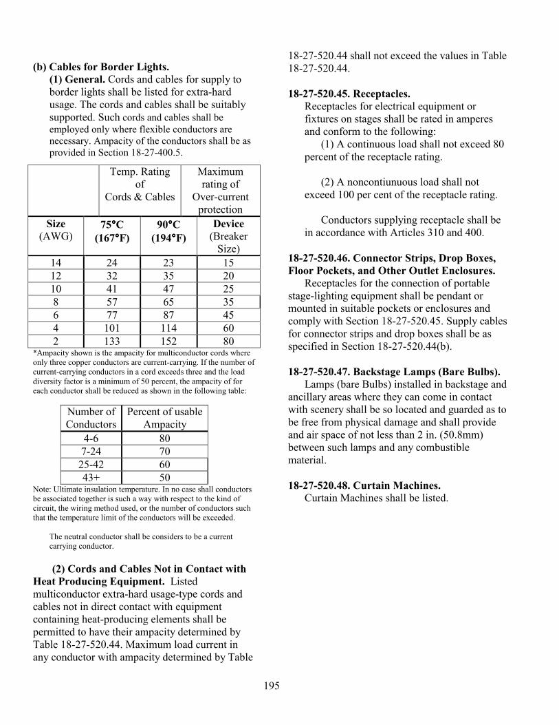
195
(b) Cables for Border Lights. (1) General. Cords and cables for supply to border lights shall be listed for extra-hard usage. The cords and cables shall be suitably supported. Such cords and cables shall be employed only where flexible conductors are necessary. Ampacity of the conductors shall be as provided in Section 18-27-400.5.
*Ampacity shown is the ampacity for multiconductor cords where only three copper conductors are current-carrying. If the number of current-carrying conductors in a cord exceeds three and the load diversity factor is a minimum of 50 percent, the ampacity of for each conductor shall be reduced as shown in the following table:
Number of Conductors
Percent of usable Ampacity
4-6 80 7-24 70 25-42 60 43+ 50
Note: Ultimate insulation temperature. In no case shall conductors be associated together is such a way with respect to the kind of circuit, the wiring method used, or the number of conductors such that the temperature limit of the conductors will be exceeded.
The neutral conductor shall be considers to be a current carrying conductor. (2) Cords and Cables Not in Contact with
Heat Producing Equipment. Listed multiconductor extra-hard usage-type cords and cables not in direct contact with equipment containing heat-producing elements shall be permitted to have their ampacity determined by Table 18-27-520.44. Maximum load current in any conductor with ampacity determined by Table
18-27-520.44 shall not exceed the values in Table 18-27-520.44. 18-27-520.45. Receptacles.
Receptacles for electrical equipment or fixtures on stages shall be rated in amperes and conform to the following: (1) A continuous load shall not exceed 80 percent of the receptacle rating. (2) A noncontiunuous load shall not exceed 100 per cent of the receptacle rating.
Conductors supplying receptacle shall be in accordance with Articles 310 and 400.
18-27-520.46. Connector Strips, Drop Boxes, Floor Pockets, and Other Outlet Enclosures.
Receptacles for the connection of portable stage-lighting equipment shall be pendant or mounted in suitable pockets or enclosures and comply with Section 18-27-520.45. Supply cables for connector strips and drop boxes shall be as specified in Section 18-27-520.44(b). 18-27-520.47. Backstage Lamps (Bare Bulbs).
Lamps (bare Bulbs) installed in backstage and ancillary areas where they can come in contact with scenery shall be so located and guarded as to be free from physical damage and shall provide and air space of not less than 2 in. (50.8mm) between such lamps and any combustible material. 18-27-520.48. Curtain Machines.
Curtain Machines shall be listed.
Temp. Rating of
Cords & Cables
Maximum rating of
Over-current protection
Size (AWG)
75°°°°C (167°°°°F)
90°°°°C (194°°°°F)
Device (Breaker
Size) 14 24 23 15 12 32 35 20 10 41 47 25 8 57 65 35 6 77 87 45 4 101 114 60 2 133 152 80
196
PART D PORTABLE SWITCHBOARDS ON STAGE 18-27-520.50. Road Show Connection Panel (A Type of Patch Panel).
A panel designed to allow for road show connection of portable stage switchboards to fixed lighting outlets by means of permanently installed supplementary circuits. The panel, supplementary circuits, and outlets shall comply with (a) through (d) of this section.
(a) Load Circuits. Circuits shall terminated in grounding-type polarized inlets of current and voltage rating that match the fixed-load receptacle.
(b) Circuit Transfer. Circuits that are transferred between fixed and portable switchboards shall have all circuit conductors, including the neutral transferred simultaneously.
(c) Overcurrent Protection. The supply
devices of these supplementary circuits shall be protected by branch-circuit overcurrent protective devices. The individual supplementary circuit, within the road show connection panel and theatre, shall be protected by branch circuit overcurrent protective devices of suitable ampacity installed within the road show connection panel.
(d) Enclosure. Panel contraction shall be in
accordance with Article 384. 18-27-520.51. Supply.
Portable switchboards shall be supplied only from power outlets of sufficient voltage and ampere rating. Such power outlets shall include only externally operable, enclosed fused switches or circuit breaker mounted on stage or at the permanent switchboard I location readily accessible from the stage floor. Provisions for connection of an equipment grounding conductor shall be provided. The neutral of feeder supplying solid state, 3-phase, 4-wire dimmer systems shall be considered a current carrying conductor.
18-27-520.52. Overcurrent Protections. Circuits from portable switchboards directly
supplying equipment containing incandescent lamps or not over 300 watts shall be protected by overcurrent protective devices having a rating or setting o not over 20 amperes. Circuits for lampholder over 300 watts shall be permitted where overcurrent protection complies with Article 210. 18-27-520.53. Construction and Feeders,
Portable switchboards and feeders f or use on stages shall comply with (a) through (p) of this section. (a) Enclosure. Portable switchboards shall be placed within an enclosure of substantial construction, which shall be permitted to be so arranged that the enclosure is open during operation. Enclosures of wood shall be completely lined with sheet metal of not less than No. 24 MSG and shall be well galvanized to prevent corrosion or be of a corrosion-resistant material.
(b) Energized Parts. There shall not be exposed energized parts within the enclosure.
(c) Switches and Circuit Breakers. All switches and circuit breakers shall be of the externally operable, enclosed type.
(d) Circuit Protection. Overcurrent devices shall be provided in each ungrounded conductor of every circuit supplied through the switchboard. Enclosures shall be provided for all overcurrent devices in addition to the switchboard enclosure.
(e) Dimmers. The terminals of dimmers shall be provided with enclosures, and dimmer faceplates shall be so arranged that accidental contact cannot be readily made with the faceplate contacts.
197
(f) Interior Conductors. (1) Type. All conductors other than busbars
within the switchboard enclosure shall be stranded. Conductors shall be approved for an operating temperature of the dimming devices used in the switchboard and in no case less than the following:
(1) Resistance-type dimmers 200°C (392°F); or
(2) Reactor-type, autotransformer, and solid-
state dimmers 125°C (257°F). All control wiring shall comply with Article 725.
(2) Protection. Each conductor shall have an ampacity not less than the rating of the circuit breaker, switch, or fuse that it supplies. Circuit interrupting and bus bracing shall be in accordance with Section 18-27-110.9 and 110.10. Switchboards with inadequate short-circuit withstand rating shall be protected on the line side by current-limiting devices. The short-circuit withstand rating shall be marked on the switchboard.
Conductors shall be enclosed in metal wireways or be securely fastened in position and shall be bushed where they pass through metal.
(g) Pilot Light. A pilot light shall be provided within the enclosure and shall be so connected to the circuit supplying the board that the opening of the master switch will no cut off the supply to the lamp. This lamp shall be on an individual branch circuit having overcurrent protection rated or set at not over 15 amperes.
(h) Supply Conductors.
(1) General. The supply to a portable switchboard shall be by means of extra-hard usage cords or cables. The supply cords or cable shall terminate within the switchboard enclosure, in an externally operable fused master switch or circuit breaker, or in a connector assembly identified for the purpose. The supply cords or cable (and connector assembly) shall have sufficient ampacity to carry the total load connected to the
switchboard and shall be protected by overcurrent devices. (2) Single-Conductor Cables. Single-conductor portable supply cable set shall not be smaller than No. 1 conductors. The equipment grounding conductor shall not be smaller than No. 6 conductor. Single conductor grounded neutral cables for a supply shall be sized as per Section 18-27-520.539(o)(2).
Where single conductors are paralleled for increased ampacity, the paralleled conductors shall be of the same length, type and size. Single conductor supply cables shall be grouped together but not bundled.
The equipment grounding conductor shall be permitted to be of a different type, provided it meets the other requirements of this section, and it shall be permitted to be reduced in size as permitted by Section 18-27-250.122. Grounded (neutral) and equipment grounding conductors shall be identified in accordance with Sections 18-27-200.6, 250.134(b), and 310.12. Grounded conductors shall be permitted to be identified by marking at least the first 6 in. (152.4 mm) from both ends of each length of conductor with white or natural gray. Equipment grounding conductors shall be permitted to be identified by marking at least the first 6 in. (152.4 mm) from both ends of each length of conductor with green or green with yellow stripes.
Where more than one nominal voltage exists within the same premises, each ungrounded system conductor shall be identified by system.
(3) Supply Conductors Not Over 10ft (3.05 m) Long. Where supply conductors do not exceed 10ft (3.05 m) in length between supply and switchboard or supply and a subsequent overcurrent device, the supply conductors shall be permitted to be reduced in size where all of the following conditions are met:
(a) The ampacity of the supply conductors shall be at least one-quarter of the ampacity of the supply overcurrent protection device.
198
(b) The supply conductors shall terminate
in a single overcurrent protection device that will limit the load to the ampacity of the supply conductors. This single overcurrent device shall be permitted to supply additional overcurrent devices on its load side.
(c) The supply conductors shall not
penetrate walls, floors, or ceiling or be rung through doors or traffic areas. The supply conductors shall be adequately protected from physical damage.
(d) The supply conductors shall be
suitably terminated in an approved manner.
(e) Conductors shall be continuous without
splices or connectors.
(f) Conductors shall not be bundled.
(g) Conductors shall be supported above the floor in an approved manner.
(4) Supply conductors Not Over 20 ft (6.1
m) Long. Where supply conductors do not exceed 20 ft (6.1 m) in length between supply and switchboard or supply and a subsequent overcurrent protection device, the supply conductors shall be permitted to be reduced in size where all of the following conditions are met:
(a) The ampacity of the supply conductors shall be at least one-half the ampacity of the supply overcurrent protection device.
(b) The supply conductors shall terminate in a single overcurrent protection device that will limit the load to the ampacity of the supply conductors. This single overcurrent device shall be permitted to supply additional overcurrent devices on its load side.
(c) The supply conductors shall not penetrate walls, floors, or ceiling or be rung through doors or traffic areas. The supply conductors shall be adequately protected from physical damage.
(d) The supply conductors shall be suitably terminated in an approved manner.
(e) The supply conductors shall be supported in an approved manner at least 7 ft (2.13 m) above the floor except at terminations.
(f) The supply conductors shall not be bundled.
(g) Tap conductors shall be in unbroken lengths.
(i) Cable arrangement. Cables shall be protected by bushings where they pass through enclosures and shall be arranged so that tension on the cable will not be transmitted to the connections. Where power conductors pass through metal, the requirements of Section 18-27-300.20 shall apply.
(j) Number of Supply Interconnections.
Where connectors are used in a supply conductor, there shall be a maximum number of three interconnections (mated connector pairs) where the total length from supply to switchboard does not exceed 100 ft (30.5 m). In cases where the total length from supply to switchboard exceeds 100 feet (30.5 m), one additional interconnection shall be permitted for each additional 100 ft (30.5 m) of supply conductor.
(k) Single-Pole Separable Connectors.
Where single-pole portable cable connectors are used, they shall be listed and of the locking type. Sections 18-27-400.10 and 410.56 shall not apply to listed assemblies utilizing listed single-pole separable connectors. Where paralleled sets of current-carrying, single-pole separable connectors are provided as input devices, they shall be prominently labeled with a warning indicating the
199
presence of internal parallel connections. The use of such connectors shall comply with at least on of the following conditions:
(1) Connection and disconnection of
connectors are only possible where the supply connectors are interlocked to the source and it is not possible to connect or disconnect connectors when the supply is energized.
(2) Line connectors are of the listed
sequential-interlocking type so that load connectors shall be connect in the following sequence:
(a) Equipment grounding conductor
connection; (b) Grounded circuits conductor
connection, if provided; ((c) Ungrounded conductor connection,
and that disconnection shall be in the reverse order.
(3) A caution notice shall be provided adjacent to the line connectors indicating that plug connection shall be in the following order:
(a) Equipment grounding conductor
connection; (b) Grounded circuits conductor
connection, if provided; (c) Ungrounded conductor connection, and
that disconnection shall be in the reverse order.
(I) Protection of Supply conductors and
Connectors. All supply conductors and connectors shall be protected against physical damage by an approved means. This protection shall not be required in raceways.
(m) Flanged Surface Inlets. Flanged surface inlets (recessed plugs) that are used to accept the power shall be rated in amperes.
(n) Terminals. Terminals to which stage cables are connected shall be so located as to permit convenient access to the terminals.
(o) Neutral
(1) Neutral Terminal. In portable switchboard equipment designed for use with 3-phase, 4-wire with ground supply, the supply neutral terminal, its associated busbar, or equivalent wiring, or both shall have an ampacity equal to at least twice the ampacity of the larges ungrounded supply terminal. Exception: Where portable switchboard equipment is specifically constructed and identified to be internally converted in the field in an approved manner, from use with a balance 3-phase 4-wire with ground supply to a balanced single-phase, 3-wire grounded supply, the supply neutral terminal and its associated busbar, equivalent wiring, or both shall have an ampacity equal to at least that of the largest ungrounded single-phase supply terminal.
(2) Supply Neutral. The power supply lines for portable switchboards shall be sized considering the neutral as a current-carrying conductor. Where single-conductor feeder cables, not installed in raceways are used on multiphase circuits, the grounded neutral conductor shall have an ampacity of a least 130 percent of the ungrounded circuit conductors feeding the portable switchboard.
(p) Qualified Personnel. The routing of portable supply conductors, the making and breaking of supply connectors and other supply connections, and the energization and de-energization of supply services shall be performed by qualified personnel, and portable switchboards shall be so marked, indicating this requirement in permanent and conspicuous manner.
200
PART E. PORTABLE STAGE EQUIPMENT OTHER THAN SWITCHBOARDS. 18-27-520.61. Arc Lamp Fixtures.
Arc lamp fixtures, including enclosed are lamp fixtures and associated ballasts, shall be listed. Interconnecting cord set and interconnecting cords and cables shall be extra-hard usage type and listed. 18-27-520.62. Portable Power Distribution Units.
Portable power distribution units shall comply with (a) through (e) of this section. .
(a) Enclosure. The construction shall be such that no current-carrying part will be exposed.
(b) Receptacles and Overcurrent Protection. Receptacles shall comply with Section 18-27-520.45 and shall have branch-circuit overcurrent protection in the box. Fuses and circuit breaker shall be protected against physical damage. Cords or cable supplying pendant receptacles shall be listed for extra-hard usage.
(c) Busbars and Terminals. Busbars shall have an ampacity equal to the sum of the ampere ratings of all the circuits connected to the busbar. Lugs shall be provided for the connection of the mast cable.
(d) Flanged Surface Inlets. Flanged surface
inlets (recessed plugs) that are used to accept the power shall be rated in amperes.
(e) Cable Arrangement. Cables shall be
adequately protected where they pass through enclosures and be arranged so that tension on the cable will not be transmitted to the terminations.
18-27-520.63. Bracket Fixture Wiring.
(a) Bracket Wiring. Brackets for use on scenery shall be carried through to the back of the scenery where a bushing shall be placed on the end of the stem. Externally wired brackets or other fixtures shall be permitted where wired with
cords designed for hard usage that extend through scenery and without joint or splice in canopy of future back and terminate in an approved-type stage connector located within 18 in (457 mm) of the fixture.
(b) Mounting. Fixtures shall be securely fastened in place.
18-27-520.64. Portable Strips.
Portable strips shall be constructed in accordance with the requirements for border lights and proscenium side lights in Section 18-27-520.44(a). The supply cable shall be protected by bushings where it passes through metal and shall be so arranged that tension on the cable will not be transmitted to the connections. FPN No. 1: See Section 18-27-520.42 for wiring of portable strips. FPN No. 2: See Section 18-27-520.68(a)(3) for insulation types required on single conductors. 18-27-520.65. Festoons.
Joints in festoon wiring shall be staggered. Lamps enclosed in lanterns or similar devices of combustible material shall be equipped with guards.
18-27-520.66. Special Effects.
Electrical devices used for simulating lighting, waterfalls, and the like shall be constructed and located so that flames, sparks, or hot particles cannot come in contact with combustible material. 18-27-520.67. Multipole Branch-Circuit Cable Connectors.
Multipole branch-circuit cable connectors, male and female, for flexible conductors shall be constructed so that tension on the cord or cable will not be transmitted to the connections. The female half shall be attached to the load end of the power supply cord or cable. The connector shall be rated in amperes and designed so that differently rated devices cannot be connected together. Alternating current multipole connectors shall be polarized and comply with Sections 18-27-410.56(g) and 410.58 FPN See Section 18-27-400.10 for pull at terminals.
201
18-27-520.68. Conductors for Portables
(a) Conductor Type.
(1) General. Flexible conductors, including cable extensions, used to supply portable stage equipment shall be listed extra-hard usage cords or cables.
(2) Stand Lamps. Reinforce cord shall be permitted to supply stand lamps where the cord is not subject to sever physical damage and is protected by and overcurrent device rated at no over 20 amperes.
(3) High-Temperature Applications. A special assembly on conductors in sleeving not longer that 3.3 ft (1 m) shall per permitted to be employed in lieu of flexible cord if the individual wires are stranded and rated not less than 125°C (257°F) and the outer sleeve is glass fiber with a wall thickness of at least 0.025 in (0.635mm).
Portable stage equipment requiring flexible supply conductors with a higher temperature rating where one end is permanently attached to t he equipment shall be permitted to employ alternate suitable conductors as determined by a qualified testing laboratory and recognized test standards.
(4) Breakouts. Listed, hard usage (junior hard service) cords shall b e permitted in breakout assemblies where all of the following conditions are met: (a) The cords are utilized to connect between a single multipole connector containing two or more branch circuits and multipole two- pole, 3-wire connectors. (b) The longest cord in the breakout assembly does not exceed 20 ft (6.1m). (c) The breakout assembly is protected from physical damage by attachment over its entire length to a pipe, truss, tower, scaffold, or other substantial support structure.
(b) Conductor Ampacity. The ampacity of conductors shall be as given in Section 18-27-400.5, except multiconductor, listed extra-hard usage portable cords, that are not in direct contact with equipment containing heat-producing elements, shall be permitted to have their ampacity determined by Table 18-27-520.44. Maximum load current in any conductor shall not exceed the values in Table 18-27-520.44. 18-27-520.69. Adapters
Adapters, Two-fers, and other single and multiple circuit outlet devices shall comply with (a), (b), and (c) of this section:
(a) No Reduction in Current Rating. Each
receptacle and its corresponding cable shall have the current and voltage rating as the plug supplying it. It shall not be utilized in a stage circuit with a greater current rating.
(b) Connectors. All connectors shall be wired
in accordance with Sections 18-27-520.67. (c) Conductor Type. Conductors for adapter
and two-fers shall be listed, extra-hard usage or listed, hard usage (junior hard service) cord. Hard usage (junior hard service) cord shall be restricted in overlength to 3.3 ft (1 m). PART F. DRESSING ROOMS 18-27-520.71. Pendant Lampholders.
Pendant lampholders shall not be installed in dressing rooms.
18-27-520.72. Lamp Guards.
All exposed incandescent lamp in dress rooms, where less than 8 ft (2.44 m) from the floor shall be equipped with open-end guards riveted to the outlet box cover or otherwise sealed or locked in place. 18-27-520.73. Switches Required.
All lights and any7 receptacles adjacent to the mirror(s) installed in dressing rooms shall be controlled by wall switches installed in the dressing room(s). Each switch controlling

202
receptacles adjacent to the mirrors(s) and above the dressing table counter(s) shall be provided with a pilot light located outside the dressing room, adjacent to the door to indicate when the receptacles are energized. Other outlets installed in the dressing room shall not be required to be switched.
PART G. GROUNDING 18-27-520.81. Grounding.
All metal raceway shall be grounded. The metal frames and enclosures of all equipment, including portable and fixed switchboards, border lights and portable lighting fixtures, shall be grounded. Grounding, where used, shall be in accordance with Article 250.

203
Bibliography Schaums Outlines, Basic Electricity by Milton Gussow, M.S., McGraw Hill; 1983, ISBN 0-07-025240-8 Audels, Electrical course For Apprentices & Journeymen by Paul Rosenberg, Wiley Publishing; 2004,
ISBN 0-764-54200-1 Recommended Practice for DMX 512 by Adam Bennette, PLSA/ USITT; 1994 Basics of Power distribution, Lex Products for Chicago Spotlight, November 8, 2002 National Electrical Code Handbook, Ninth edition 2002 NFPA ISBN 0-87765-462-x Chapters of the Municipal Code of Chicago, Relating to Electrical Inspection; Effective February 7, 2001,
INDEX Publishing Corp http://www.lightlineelectronics.com/frmain.html http://vsg.cape.com/~pbaum/hmi.htm http://www.ushio.com/support_lampsafety.htm#3LAMP SAFETY & HANDLING, Xenon lamp safety http://en.wikipedia.org/wiki/Fresnel_lens www.plsn.com/cgi/issue/viewissue.cgi?category=13&id=1014056031 Chicago Daily News negatives collection, DN-0003451. Courtesy of the Chicago Historical Society.

Useful Industry Links
• LUMINAIRES (GENERICS)
• Altman Lighting Inc. (USA)
• Artistic Licence
• ADB (Belgium)
• CCT Lighting
• Full Compass (USA)
• High End Systems Moving Lights
• Robert Juliat (France)
• Opti Projection and effects luminaires and rigging
• Pulsar (UK) Chroma LED range
• RazTech (USA) Retail and domestic projectors
• Reiche & Vogel (Germany)
• Selecon
• Strand Lighting
• Strong Entertainment Lighting - Followspots
• James Thomas Engineering
• Zero 88
• MOVING LIGHTS
• ADB (Belgium)
• Articulight (NJ, USA)
• Clay Paky
• Coemar
• Coe-Tech
• Color Kinetics
• FAL
• Futurelight • High End
• Light Factor • Martin (International site)
• Martin (UK site)
• Morpheus
• SGM
• Vari*Lite
• LAMPS
• GE Lighting
• Osram
• Philips
• Sylvania
• EFFECTS LUMINAIRES / DISCO
• Abstract • American DJ

Links Continued
• LED LIGHTING
• Color Kinetics LED Fittings
• Lighting Effects Distribution LED lighting
• Lumivision Architectural Lighting (Glasgow, UK)
• Pulsar (UK) Chroma LED range
• Selador X7 range of fixtures (San Francisco/Salt Lake City, USA)
• EFFECTS / GOBOS / ELECTRICAL PROPS & PRACTICALS
(for Pyrotechnics, Smoke etc. see Theatrical Effects page)
• Apollo Design Technology Gels, gobos, scrollers (USA)
• Californeon Electroluminescent tape
• Cool Neon Bendable electroluminescent wire
• DHA Lighting (London, UK)
• Furnish That Room (UK, Mail Order)
• GlowShop Ltd. UV effects (Birmingham, UK)
• Goboland (Belgium, Europe)
• Howard Eaton Lighting Ltd (UK)
• Hungaroflash (Hungary, Europe) Strobe effects and controllers
• HVFX - High voltage special effects
• Lamps Plus Massive range of light fittings - online catalogue (USA)
• Le Mark Custom gobos in steel or glass
• Nocturn (USA) UV Effects
• Opti Projection and effects luminaires and rigging
• Par Opti Fibre-optics
• Projected Image UK Ltd (London, UK) Glass and brass custom gobos
• S&H Technical Support Starcloths and fibre-optics
• ShowLED by Amelia LED Starcloths etc.
• Skytracker Searchlights
• Surelight Electroluminescent wire (Sheffield, UK)
• Theatre FX
• Universal Fibre Optics (UK)
• UV FX (USA)
• Wildfire Inc. UV Paint/Make-up/Luminaires
• COLOUR MEDIA
• Apollo Design Technology Gels, gobos, scrollers (USA)
• Gam (US)
• Lee Filters (UK) - Excellent online catalogue showing colours grouped together
• Rosco Laboratories - Rosco Supergel, Cinegel, E Colour
• Colour Frame sizes - A.C. Lighting

Links Continued
• CONTROL / DIMMING
• ADB (Belgium)
• Anytronics
• Artistic Licence (UK)
• AVAB (Sweden)
• Avolites
• Celco
• Compulite
• Electrol (USA)
• ETC
• Entertainment Technology
• Flying Pig Systems Lighting Visualisation Software
• Goddard Design DMX Test / Distribution / Processing equipment (NY, USA)
• Horizon Technology
• Leprecon
• Light Processor
• Liteputer (Taiwan)
• MA Lighting
• Mode Lighting (Herts, UK) Dimmers and controllers
• NSI
• Pulsar
• Rubber Box Co. • Strand Lighting
• Theatrelight (New Zealand)
• Zero 88
• EQUIPMENT - ACCESS
• Aluminium Access Products - Tallescope sales and service (UK)
• EQUIPMENT - FLIGHTCASES / TOURING
• Dragon Cases - Custom flight case design and manufacture (Wales, UK)
• Le Mark - Equipment labels and tapes
• Musicase - Flight cases and bags - Dealers for ROAD READY CASES and GIG SKINZ
• S.A.M. Custom Flight Cases - Flight cases (Bristol, UK)
• Triple-A Flight Cases (UK)
• EQUIPMENT - DESIGN AIDS
• Field Template - LX design stencils
• EQUIPMENT - RIGGING
• Applied Electronics - Trussing, lifts etc (USA)
• CMS - Cable Management Supplies (UK)
• Doughty Engineering (UK, USA) Rigging products
• Exhibit and Display Truss - (Pickering, Ontario, Canada)
• H.O.F.Alutec (Germany) Rigging & Truss systems
• Opti Trilite truss

Photos and other Items used with Permission from: Altman ETC Lycian Wybron HighEnd Systems