Stack Monitoring Material and Methodology for Isokinetic ... · PDF fileRotameters:0 to 60 lpm...
48
Stack Monitoring
Transcript of Stack Monitoring Material and Methodology for Isokinetic ... · PDF fileRotameters:0 to 60 lpm...

Stack Monitoring

Stack Sampling
• Stack sampling or source sampling may bedefined as a method of collecting representativesamples of pollutant laden air/gases at the place oforigin of pollutants to determine the total amount ofpollutants emitted into the atmosphere from a givensource in a given time

Stack Sampling
• The purpose of stack sampling is to determineemission levels from plant processes to ensure theyare in compliance with any emission limits set byregulatory authorities to prevent macroenvironmental pollution.

Stack SamplingStack sampling is used for the assessment of the following:1. To determine the quantity and quality of the pollutant
emitted by the source.2. To measure the efficiency of the control equipment by
conducting a survey before and after installation3. To determine the effect on the emission due to changes in raw
materials and processes.4. To compare the efficiency of different control equipments for
a given condition.5. To acquire data from an innocuous individual source so as to
determine the cumulative effect of many such sources.6. To compare with the emission standards in order to assess
the need for local control

Stack Sampling
Source sampling is carried out in a process ventilation stack todetermine the emission rates/or characteristics of pollutants.
Planning the study:• Familiarity of the process and operations to determine the time
of cyclic operations, peak loading that might cause variations inthe characteristics.
• Method of sampling• Method of analysis of samples• Sampling time because certain industries undergo cyclic
changes• Amount of sample required• Sampling frequency

Stack Sampling
Representative sample:• Sample collected must truly represent the conditions prevailing
inside the stack.
The important considerations for accurate representativesample collection include:• Accurate measurement of pressure, moisture, humidity and gas
composition• The selection of suitable locations for sampling• Determination of the traverse point required for a velocity and
temperature profile across the cross section of the stack andsampling for particulate matter

Schematic Diagram – Sampling Train

Stack Sampling
Sampling System:
• Stack sampling is carried out by diverting a part of the gasstream through a sampling “train” of which a generalarrangement is shown below.
1 Nozzle 2 Sampling probe 3 Particulate collector 4 Gas collector5 Gas flow meter 6 Flow control valve 7 To vacuum pump
1
2 3 4 5 6 7

• The train consists of a nozzle placed in the gas stream, asampling probe through which the sample is drawn atdifferent traverses, particulate and gas collection devices, aflow measuring device and a prime mover such as avacuum pump or an ejector.
• Nozzle: It is at the end of the probe is sharp edged,pointing inward from the outside edge and the traversingprobe is made of stainless steel with glass or Teflon lining.
Stack Sampling

• For Sampling hot gases whose temperature are above 4000C, these probes are provided with a circulating coolantsystem to prevent combustion of particulate materialsinside the probe and to prevent the temperature fromexceeding the maximum allowable temperature offiltration materials.
• Devices: Collection of particulates: Filtration, wet or dryimpingement, impaction, electrostatic and thermalprecipitation
• Collection of gases: Absorption, adsorption, freeze out• Flow measurement: Use rotameter or orifice meter or dry
gas meter if the information on the total volume of the gassampled is required.
Stack Sampling
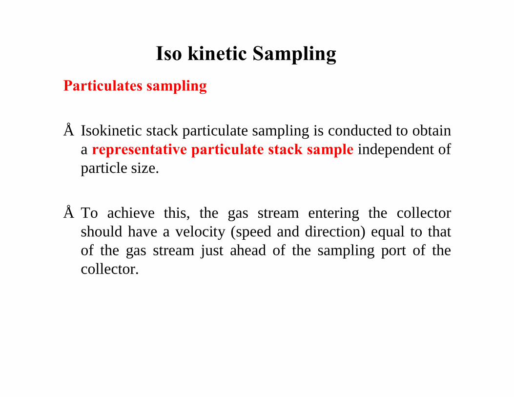
Particulates sampling
• Isokinetic stack particulate sampling is conducted to obtaina representative particulate stack sample independent ofparticle size.
• To achieve this, the gas stream entering the collectorshould have a velocity (speed and direction) equal to thatof the gas stream just ahead of the sampling port of thecollector.
Iso kinetic Sampling

Iso kinetic Sampling• Webster's dictionary defines ISO as denoting equality,
similarity, uniformity.
• Kinetic is defined as due to motion.
• Isokinetic sampling is an equal or uniform sampling ofparticles and gases in motion within the stack.
• Isokinetic source sampling is achieved when the velocityof gas entering the sampling nozzle is exactly equal tothe velocity of the approaching gas stream. Thisprovides a uniform, unbiased sample of the pollutantsbeing emitted by the source.

Different conditions…
1. Sample collection Velocity (V) > Stack gas velocity (W)
2. Sample collection Velocity (V) < Stack gas velocity (W)
3. Sample collection Velocity (V) = Stack gas velocity (W)
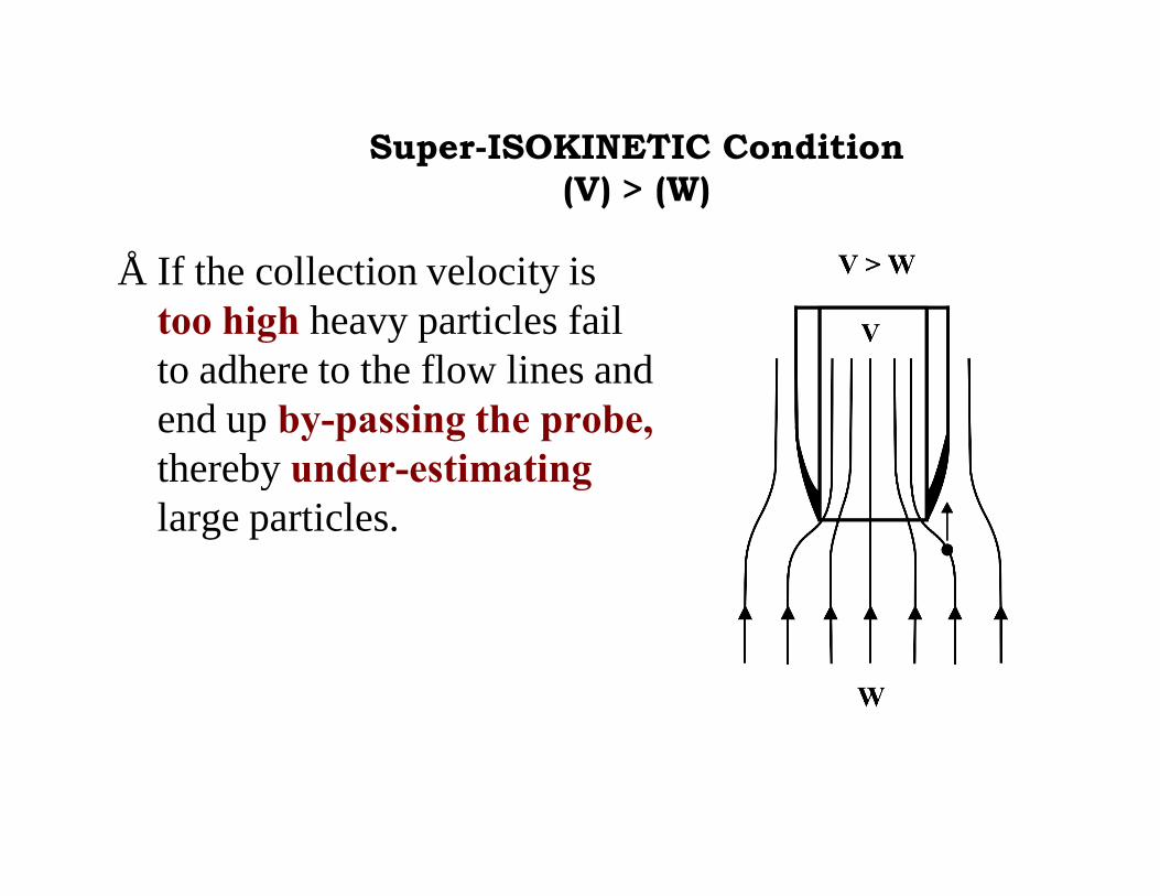
Super-ISOKINETIC Condition (V) > (W)
• If the collection velocity is too high heavy particles fail to adhere to the flow lines and end up by-passing the probe,thereby under-estimatinglarge particles.

Sub-ISOKINETIC Condition(V) < (W)
• If the sample collection velocity is too low heavy particles can enter the probe even if the flow line on which they were located passes by the probe.
• Thus too many large particles are collected.

ISOKINETIC Condition(V) = (W)
• When conducting isokinetic sampling all particles flowing toward the intake opening are equally collected.
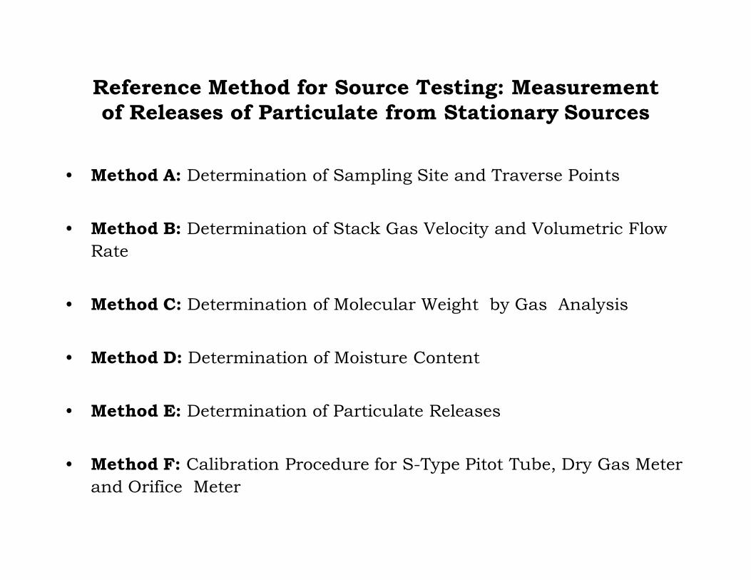
Reference Method for Source Testing: Measurement of Releases of Particulate from Stationary Sources
• Method A: Determination of Sampling Site and Traverse Points
• Method B: Determination of Stack Gas Velocity and Volumetric Flow Rate
• Method C: Determination of Molecular Weight by Gas Analysis
• Method D: Determination of Moisture Content
• Method E: Determination of Particulate Releases
• Method F: Calibration Procedure for S-Type Pitot Tube, Dry Gas Meter and Orifice Meter
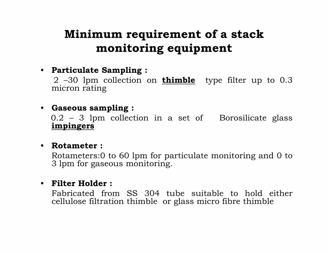
• Particulate Sampling :2 –30 lpm collection on thimble type filter up to 0.3micron rating
• Gaseous sampling :0.2 – 3 lpm collection in a set of Borosilicate glassimpingers
• Rotameter :Rotameters:0 to 60 lpm for particulate monitoring and 0 to3 lpm for gaseous monitoring.
• Filter Holder :Fabricated from SS 304 tube suitable to hold eithercellulose filtration thimble or glass micro fibre thimble
Minimum requirement of a stack monitoring equipment
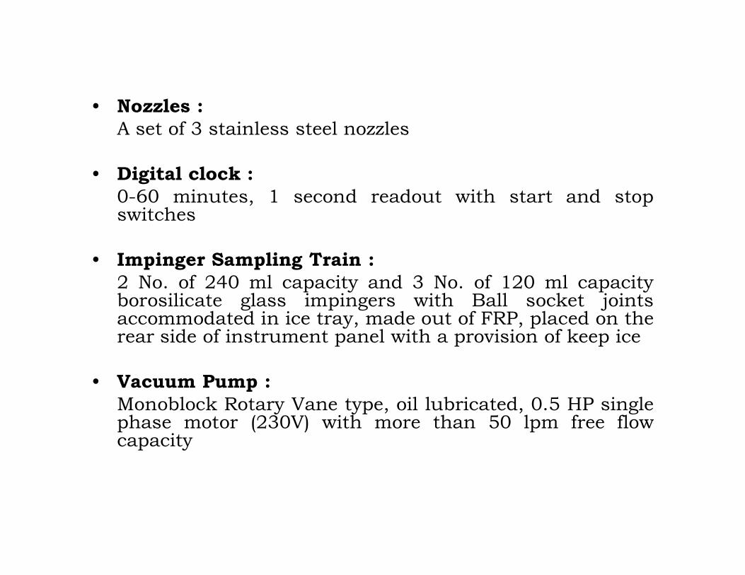
• Nozzles :A set of 3 stainless steel nozzles
• Digital clock :0-60 minutes, 1 second readout with start and stopswitches
• Impinger Sampling Train :2 No. of 240 ml capacity and 3 No. of 120 ml capacityborosilicate glass impingers with Ball socket jointsaccommodated in ice tray, made out of FRP, placed on therear side of instrument panel with a provision of keep ice
• Vacuum Pump :Monoblock Rotary Vane type, oil lubricated, 0.5 HP singlephase motor (230V) with more than 50 lpm free flowcapacity

• Thermocouple:Thermocouple sensor shall be provided with analog ordigital dial gauge capable of measuring temperature from0 to 6000C covered with stainless steel or mild steelcasing with acid resistant treatment.
• Manometer:To measure differential pressure
• Pitot tube:Pitot tube shall be modified “S- type” fabricated from SS304 or equivalent grade. The construction feature shouldbe as per United States Environmental Protection Agency(EPA) regulation, Method 2, Given in Figures 1.1 and 1.2(A) ii. The construction feature shall be such that thecoefficient of the pitot tube is above 0.95.
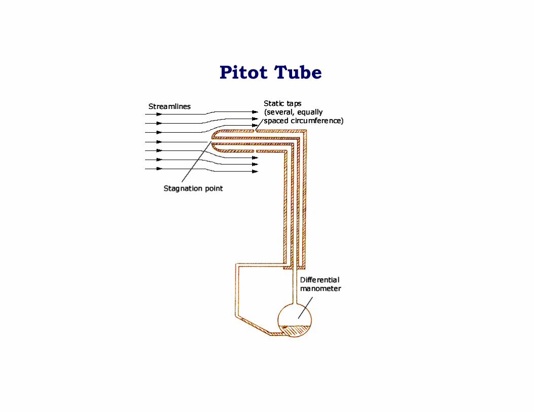
Pitot Tube

Method A: Determination of Sampling Site and Traverse Points
• Applicability• Principle• Location of Sampling Site• Determination of Traverse Points• Location of Traverse Points• Confirmation of Cyclonic and Reverse Flow
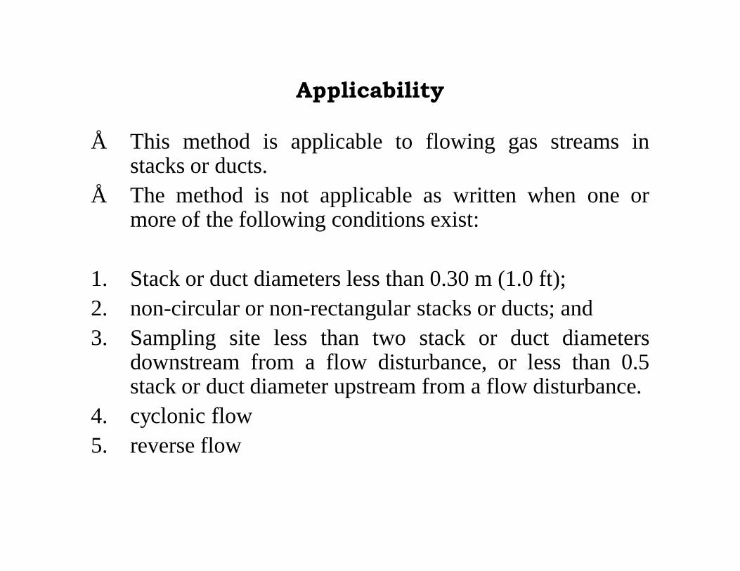
Applicability
• This method is applicable to flowing gas streams instacks or ducts.
• The method is not applicable as written when one ormore of the following conditions exist:
1. Stack or duct diameters less than 0.30 m (1.0 ft);2. non-circular or non-rectangular stacks or ducts; and3. Sampling site less than two stack or duct diameters
downstream from a flow disturbance, or less than 0.5stack or duct diameter upstream from a flow disturbance.
4. cyclonic flow5. reverse flow

Location of Sampling Site
• Select a site in a straight section of stack located at leasteight stack diameters downstream and two stackdiameters upstream of any flow disturbance such as a bend,expansion, contraction, visible flame, junction, or stackexit.
• Size of sampling point: 7-10 cm

Determination of Traverse Points
• When the sampling site is located at least eight diametersdownstream and two diameters upstream from a flowdisturbance, the required minimum number of traversepoints for a circular or rectangular cross section isdetermined from Table A-1.

Table A-1: Minimum Number of Traverse Pointsfor Sampling Sites that Meet the Eight- and Two-diameter Criteria
Stack or Duct Diameter (m)
Required Minimum Number of Traverse Points
Circular Duct Rectangular Duct
> 0.61 12 12
0.30 to 0.61 8 9
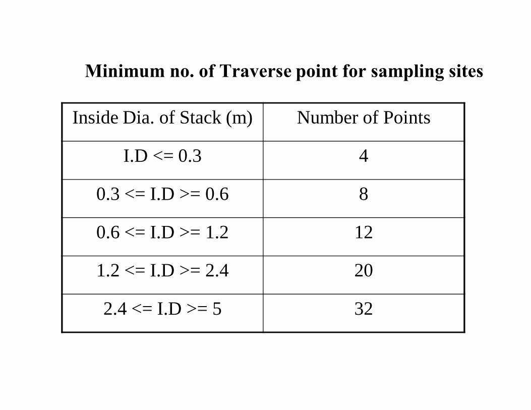
Minimum no. of Traverse point for sampling sites
Inside Dia. of Stack (m) Number of Points
I.D <= 0.3 4
0.3 <= I.D >= 0.6 8
0.6 <= I.D >= 1.2 12
1.2 <= I.D >= 2.4 20
2.4 <= I.D >= 5 32

Determination of Traverse Points
• When the eight- and two-diameter criteria cannot besatisfied, the minimum number of traverse points isdetermined either from Figure A-1 for particulatesampling or from Figure A-2 for velocity measurement.

Figure A-1: Minimum Number of Traverse Points for
Particulate Sampling

Figure A-2: Minimum Number of Traverse Points for Velocity
Measurement

Location of Traverse Points onCircular and RectangularCross Sections Divided into
Twelve Equal Areas

Location of Traverse Points in Circular Stacks

Method B: Determination of Stack Gas Velocity and Volumetric Flow Rate
• The average gas velocity in a stack or duct is determinedfrom the gas density and from the measurement of velocitypressure with an S-type pitot tube.
• A standard pitot tube may be used where plugging of thetube openings due to particulate matter and/or moisture isnot likely to occur.
• Stack gas volumetric flow rate is determined frommeasurements of stack gas velocity, temperature, absolutepressure, dry gas composition, moisture content, and stackdiameter.

Determination of gas composition:• Gas composition can be determined by Orsat apparatus.• The gas is collected in the Orsat apparatus and analyzed
for the composition of CO2, O2 and CO in the same order and the remaining is assumed to be nitrogen.
• Molecular weight of gas = Σ Mx Bx
Where Mx = Molecular weight of CO2, O2 and CO and N2 (44, 32, 28 and 28 respectively) and Bx represent % of gases
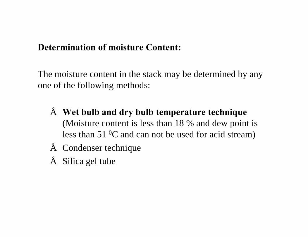
Determination of moisture Content:
The moisture content in the stack may be determined by any one of the following methods:
• Wet bulb and dry bulb temperature technique(Moisture content is less than 18 % and dew point is less than 51 0C and can not be used for acid stream)
• Condenser technique• Silica gel tube
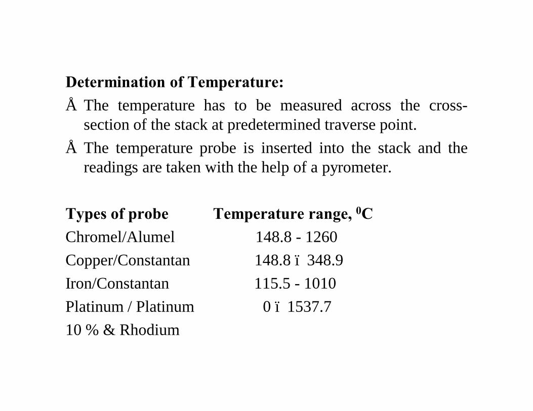
Determination of Temperature:• The temperature has to be measured across the cross-
section of the stack at predetermined traverse point.• The temperature probe is inserted into the stack and the
readings are taken with the help of a pyrometer.
Types of probe Temperature range, 0CChromel/Alumel 148.8 - 1260Copper/Constantan 148.8 – 348.9Iron/Constantan 115.5 - 1010Platinum / Platinum 0 – 1537.710 % & Rhodium

S-type Pitot Tube and Manometer Assembly
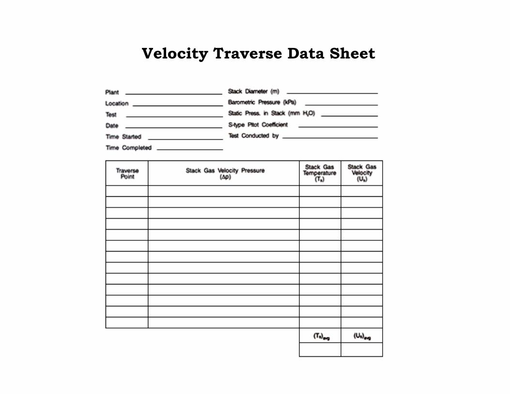
Velocity Traverse Data Sheet
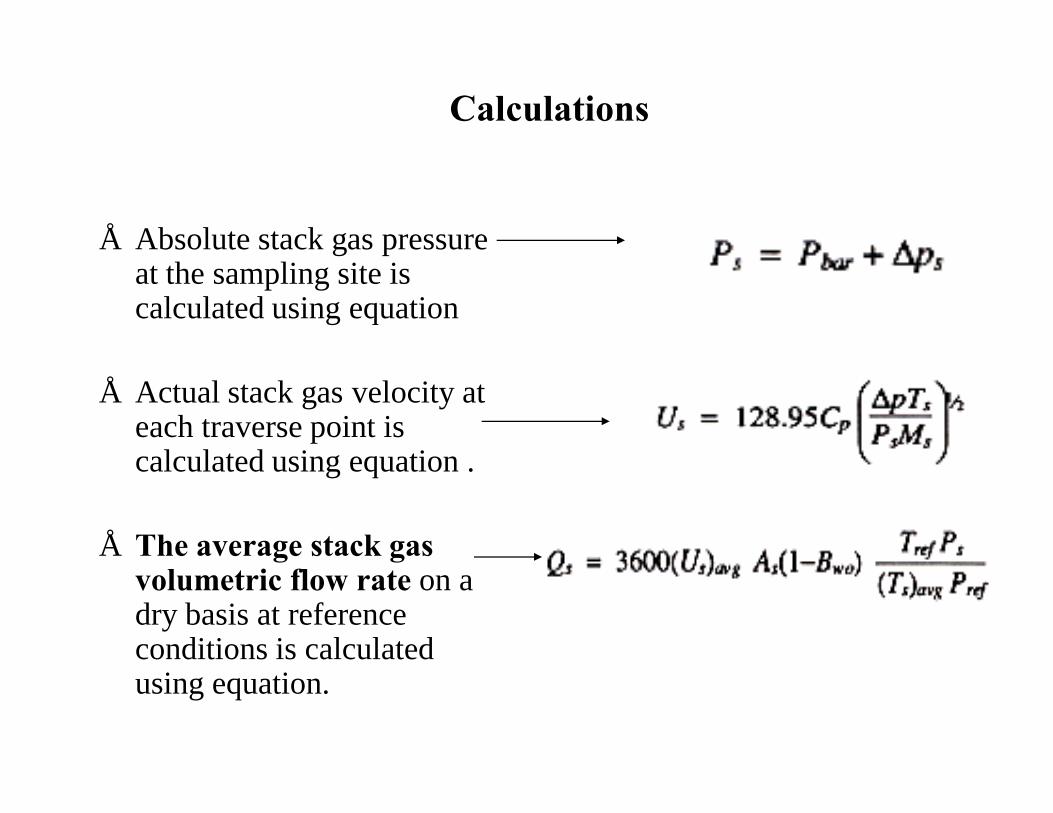
Calculations
• Absolute stack gas pressure at the sampling site is calculated using equation
• Actual stack gas velocity at each traverse point is calculated using equation .
• The average stack gas volumetric flow rate on a dry basis at reference conditions is calculated using equation.

Typical sampling provision

Preparation of the Sampling Train


Steps for Stack Sampling
Procedure for particulate matter sampling1. Determine the gas composition and correct to moisture
content.2. Determine the temperature and velocity at each traverse
point.3. Determine the empty weight of the thimble (W1).4. Mark out the traverse points on the probe. The marks are
normally fixed by tying with asbestos thread.5. Check all points for leakages.6. Determine the flow rate to be sampled under isokinetic
condition.

Steps for Stack Sampling
Procedure for particulate matter sampling7. Insert the probe at the traverse point 1, very close to the
stack. Start the pump and adjust the flow so that therotameter reads the predetermined value.
8. Switch ff the pump at the end of sampling time.9. Read the vacuum at the dry gas meter (DGM) and also the
temperature.10. Move the probe to subsequent traverse points by repeating
the steps five to eight.11. After completion of collection of samples, remove the
probe and allow it to cool.

Steps for Stack SamplingProcedure for particulate matter sampling12. Remove the thimble carefully. Some of the dust would
have adhered to the nozzle. This should be removed bytrapping and transferred to the thimble.
13. Weight the thimble with the sample. The difference inweight gives the dust collected.
14. The volume of sample collected in either given by the drygas meter (m3) or by sampling rate given by rotametermultiplied by the sampling time.
15. Hence from (13) and (14), the emission rate can becalculated. This will be at DGM conditions. This is to becorrected for temperature and pressure so as to obtainvalues for standard conditions.
Steps for Stack SamplingSample recovery:
• After cooling, the outside of probe assembly is cleanedwith cotton waste. Disconnect the nozzle.
• Remove the thimble and keep it in a clean glass beaker.• The particulate matter adhered to the inside walls of the
nozzle, should be transferred carefully to the thimble.• Weigh the thimble with sample (W2).• The difference in weight (W2- W1) will give the particulate
collected