Sharon Mawhinney, Evans & Peck - Standards Development: Turnouts and Other Special Trackwork

Vancouver, 6-11 October 2013
Stability Analysis of Turnouts in Continuous Welded Rail Track Ralph Zhang* and Dr Helen Wu** * Civil engineering of North South Corridor, Wagga Wagga Office, Australian Rail Track Corporation ** Senior Lecturer. The School of Computing, Engineering, and Mathematics, University of Western Sydney
SUMMARY
Continuous Welded Rail (CWR) has been acknowledged as the greatest technical achievement in railway technology since the second half of last century. However, by eliminating rail joints and gaps between rail sections, the ambient temperature change during the year from severe cold winter to hot summer, high thermal stress exist and change within the welded rails. In some circumstances, if the CWR structure is combined with poor track maintenance, it may cause problems such as track buckling, broken rails, or derailment. As part of ARTC’s North-South Corridor Strategy some new concrete-bearer turnouts have been installed to connect the new passing loops and to strengthen the Main South Line (Sydney to Albury) during the last two years. Same as the old turnouts, almost all the turnouts on the main line are welded within the adjacent CWR tracks, which has significantly integrated the track structure and decreased the maintenance cost. However, regarding the turnouts which are welded into CWR track, especially for the turnouts which are directly connected to long welded rails (located outside of stations), they are usually under very high thermal stress which is transferred by the CWR in the longitudinal direction. In this scenario, both the stability and functionality of turnouts may be problematic. In this paper the turnout defects related to the high longitudinal stress have been reviewed and analysed. In addition, further analysis and explanation of the defects and some data calculations including non-linear finite element models were utilised for this study. Moreover, based on the in-field inspection, analysis, and numerical studies, some findings are presented and recommendations for maintaining the stability of turnouts in CWR track are given.
INTRODUCTION
Continuous Welded Rails (CWR) has been acknowledged as the greatest technical achievement in railway technology since the second half of last century. Its major advantages including: removal of rail joint, significantly decreased the impact load from the wheel, great integration and evenness of the rail surface, as well as significantly lower maintenance cost. Moreover, it also provided the technical possibility and base for high speed and heavy haul revenue. Hence, it has been widely accepted as a standard for modern railway tracks. However, by eliminating the rail joints and gaps between the rail sections, combined with the temperature change during the year from severe cold in winter to hot summer, extremely high thermal stress exist within the welded rails. In some circumstances, if the CWR structure is combined with poor track maintenance, it will result in track buckling, broken rails, or derailment. Information from the Australian Transportation Safety Bureau, indicates that within the past decade about 50% of costly train derailments are directly caused by or related to the track buckling. As part of ARTC’s North-South Corridor Strategy, some new concrete-bearer turnouts have been installed to connect the newly constructed passing loops and to strengthen the Main South Line (Sydney to Albury) in the past 2 years. These concrete bearer turnouts include Vossloh Cogifer and VAE. As per the old turnouts, almost all the turnouts on the main line are welded within the adjacent CWR tracks, which has significantly integrated the track structure and decreased the maintenance cost. However, regarding the turnouts which are welded into CWR track, especially for the turnouts which are directly connected to long welded rails (located outside of stations), they are usually under very high thermal stress which is transferred by the CWR in the longitudinal direction. In this scenario, both the stability and functionality of turnouts may be problematic.

Ralph Zhang & Helen Wu Stability Analysis of Turnouts in Continuous Welded Rail Track University of Western Sydney
Vancouver, 6-11 October 2013
NOTATION
tPmax ---- The compressive force in the CWR at the maximum temperature increase;
PΔmax ---- The maximum additional thermal compressive force in the stock rail at the rear of the switch;
[P] ---- The maximum allowable thermal compressive force. [P] = PN / K. (where: PN is the critical thermal compressive force; K is the safety factor, using 1.25);
Q ---- Effective ballast lateral resistance, for the timber bearer Q =62 N/cm, and for the concrete bearer Q = 87 N/cm;
R′1
---- The effective curvature of turnout track, for the timber bearer using 1.25×10⁻⁵ cm-1, for the concrete
bearer using 1.50×10⁻⁵ cm-1;
ef0 ---- The initial elastic bending deflection, for the timber bearer using 0.25 cm, for the concrete bearer using 0.30 cm;
f ---- Deflection of deformation curve, using 0.2 cm;
β ---- The factor of track stiffness, using 2;
EJy ---- Bending resistance in the lateral direction.
TURNOUT DEFECTS THAT RELATED TO HIGH LONGITUDINAL STRESS
From turnout maintenance experience on ARTC’s Main South Line, the defect characteristics that relate to the high longitudinal stress include: poor alignment, bearers not square, splice rail and point rail separated (for the assembly crossing), anti-creep device in the wrong position, crossing bolt bent or broken, crossing chock in the wrong position, stock rail creep, closure rail bent, etc. Timber-Bearer Turnout
The turnout defects that relate to high longitudinal thermal stress are tabulated in Table 1.
Defect Type Reasons and Details of the Defect
Track alignment in front or behind turnout
High longitudinal stress within stock rails or closure rails
Inadequate neutral temperature of the adjacent CWR track
Temperature of turnout installation significantly different to adjacent CWR track
Position of bearers Not square cause by stock rail creep
Not square cause by closure rail creep
Splice rail and point rail separate
Stock rail creep
Heel block broken
Crossing bolt bent/broken/ineffective
Crossing chock (spacer block) in wrong position
Gap between point rail and spacer block
Left and right chocks unevenly creep
Stock rail creep Inadequate neutral temperature of the adjacent CWR track
Temperature of turnout installation significant different to the adjacent CWR track
Thermit weld in front of switch toe failure
Fasteners ineffective
Heel block broken
Closure rail bent Temperature of turnout installation or closure rail are significant different to

Ralph Zhang & Helen Wu Stability Analysis of Turnouts in Continuous Welded Rail Track University of Western Sydney
Vancouver, 6-11 October 2013
Defect Type Reasons and Details of the Defect
adjacent CWR track
Stock rail or switch creep Table 1: The turnout defects that related to high longitudinal thermal stress with the timber-bearer
turnouts
Figure 1: Misalignment behind the crossing of turnout
Figure 2: Relative creep (gap) between splice rail and point rail at the crossing area

Ralph Zhang & Helen Wu Stability Analysis of Turnouts in Continuous Welded Rail Track University of Western Sydney
Vancouver, 6-11 October 2013
Figure 3: Left and right chocks unevenly creep at the toe of point rail
Figure 4: Rail chair broken and creep in the longitudinal direction (Evidence of rail creep within the
turnout)
Concrete-Bearer Turnout For the new concrete-bearer turnouts there are no heel blocks. The switch stops and the fastening systems hold the stock rail and the switch in the correct position. In these designs one or two anti-creep devices are fitted between each switchblade and its matching stock rail near the heel end of the switch rail. This is intended to prevent differential longitudinal movement of the switchblades relative to their stock-rails caused through rail creep. On the Main South line, there are three types of anti-creep devices manufactured by Vossloh Cogifer, VAE, and PRE. The Vossloh Cogifer turnouts use one set on each pair of switch and stock rails as shown in Figure 5.

Ralph Zhang & Helen Wu Stability Analysis of Turnouts in Continuous Welded Rail Track University of Western Sydney
Vancouver, 6-11 October 2013
Figure 5: The anti-creep device of Vossloh Cogifer turnout
For the VAE concrete-bearer turnouts, the two sets anti-creep devices are applied on the Main South Line, it has two devices on each pair of switch and stock rails, as shown in Figure 6.
Figure 6: The VAE turnout’s double anti-creep device
For the anti-creep device, both the condition and position need to be inspected. Checks for the condition include if it is shattered, missed, or broken. The relative position between the T block and ∏ block also needs to be monitored.
An anti-creep device in the wrong position (e.g. the “T” block very tightly against one side of the “∏” block) transfers the additional stress to the stock rail (the additional stress from the side direction). This situation is even worse for a swing nose turnout.
Since a turnout is a very complex track structure, one weak component can result in many types of defects on other components, particularly the heel block. The poor condition of a heel block is linked with many types of defects and it is very difficult to clearly represent them. Hence, in this section, the defect types of heel block only focus on the defects on heel block itself. Its effects and relative defects resulting on other components will not be discussed here but presented in the other sections.
The Defect and Remedial Action of Anti-Creep Device
When inspecting the Vossloh Cogifer turnouts or the VAE and PRE concrete bearer turnouts, which are welded in the CWR track, special attention should be paid to the condition and position of the anti-creep devices. If the anti-creep devices are damaged or its components are in the incorrect position, for example, the “T” block very tightly against one side of the “∏” block, as shown in Figure 7 and 8, this means creep is occurring at the stock rail, switch, or both. In addition, for the structural mechanism within the point area, in this situation, the straight stock rail is not only under the longitudinal stress from the CWR track, but also under the turnout stress transferred by the switch.
“T” block
“∏” block

Ralph Zhang & Helen Wu Stability Analysis of Turnouts in Continuous Welded Rail Track University of Western Sydney
Vancouver, 6-11 October 2013
Figure 7: The anti-creep device of Cogifer turnout in the wrong position (e.g. the “T” block very
tightly against one side of the “∏” block)
Figure 8: The anti-creep devices of VAE concrete sleeper turnout in the wrong position (e.g. the “T”
block very tightly against one side of the “∏” block)
LONGITUDINAL STRESS DISTRIBUTION WITHIN TURNOUT AREA Thermal Force Transfer in the Turnout The longitudinal stress distribution within the turnout area is generally uneven. However, the longitudinal thermal stress transfers though a turnout is quite similar for the both fixed-crossing turnouts and switchable-crossings turnouts. The transfer of the thermal longitudinal stress within the turnout area is, as shown in Figure 9.
Figure 9: Schematic diagram of a turnout (the arrows represent the direction of thermal force
transfer within the turnout when the ambient temperature is increased)
From Figure 9, it can be seen that the direction and route of thermal force is transferred from the rear of a crossing to the toe of switch. The force goes through the crossing and is transferred longitudinally along the closure rails, then goes to the stock rails of the switch via the connection devices at the rear of the switch (for concrete bearer turnouts the device is the anti-creep devices). In addition, with the thermal force going through the closure rails between the crossing and switch, the rail may creep in the longitudinal direction together with the bearers. During the above procedure, part of the thermal force can be transferred to the

Ralph Zhang & Helen Wu Stability Analysis of Turnouts in Continuous Welded Rail Track University of Western Sydney
Vancouver, 6-11 October 2013
stock rails via the heel blocks or anti-creep devices which are located at the end of switch rails. Hence, the structural design of the thermal force transfer devices (such as heel block and anti-creep devices) plays a very important role in ensuring the stability of the turnouts which are located in the CWR track. The Functionalities of the Anti-Creep Device in Thermal Stress Transfer In turnout designs one or two anti-creep devices are fitted between each switchblade and its matching stock rail near the heel end of the switch rail. This is designed to prevent differential longitudinal movement of the switchblades relative to their stock rails caused through rail creep. One of the most important functions of the anti-creep device is to transfer the thermal load. It is consists of two parts a “∏” block and a “T” block, as shown in Figure 5. There are gaps between these two blocks, usually from 4 mm to 7 mm. When creep occurs between the switch and stock rail under thermal force, the two blocks will move closer in one side and away on the other side. With the increasing of the thermal force, these blocks will contact each other on one side, and then thermal stresses are transferred from the switch to the stock rail via the anti-creep blocks, as shown in Figure 7. This design can not only help to maintain the switch in its proper location when the creep occurs it can also release part of the thermal stress applied on the stock rail. Longitudinal Stress Distribution within the Turnout in CWR When the rail temperature changes from 5°C to 35°C, the additional thermal force changes in the main stock rail and its influence range is shown in Figure 10, and its variation with the change of rail temperature is shown in Figure 11.
Variation of Additional Thermal Force in Main Direction Stock Rail in Turnout
-150
-100
-50
0
50
100
150
200
-40 -30 -20 -10 0 10 20 30 40 50 60 70
Distance (m)
Add
ition
al T
herm
al F
orce
in M
ain
Dire
ctio
n St
ock
Rai
l (kN
)
Temperature Increase 5 degreesTemperature Increase 15 degreesTemperature Increase 25 degreesTemperature Increase 35 degrees
Figure 10: Variation of additional thermal force in the main direction stock rail in turnout
In Figure 10, the zero point of the coordinate is the end/rear of the switch. It can be found that the maximum extension load caused by the temperature increasing is exactly located at this location. It should be noted that for a range in rail temperature, changing in the turnout from 5°C to 35°C, the two steel blocks of the anti-creep device do still not contact each other.
Figure 11: The variation with the changing of rail temperature
Ralph Zhang & Helen Wu Stability Analysis of Turnouts in Continuous Welded Rail Track University of Western Sydney
Vancouver, 6-11 October 2013
From the above two figures it can be seen that the additional thermal force in the stock rail will increase with the increasing of the rail temperature. The increasing rate of the additional force is about 22.9% to 26.7%. At this stage the two blocks of the anti-creep devices have not moved tightly against each other on one side and the ratio of increase slows down. However, once the two blocks are against each other, the ratio of the additional thermal force increase is intensified. In addition, with the increasing of the rail temperature, the influence length of the additional thermal force is also extended.
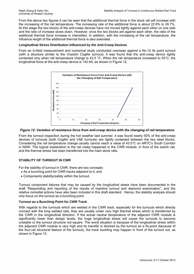
Longitudinal Stress Distribution Influenced by the Anti-Creep Devices
From an in-field measurement and numerical study conducted overseas against a No.12 fix point turnout (with a structure similar to the Vossloh Cogifer turnout), it was found that the anti-creep device tightly contacted only when rail temperature change is 43.5 °C. When the rail temperature increased to 55°C, the longitudinal force at the anti-creep device is 142 kN, as shown in Figure 12.
Variation of Resistance Force from Anti-Creep Device with the Changing of Rail Temperature
0
20
40
60
80
100
120
140
160
0 10 20 30 40 50 60
Changing of Rail Temperature (Degree)
Res
ista
nce
Forc
e (k
N)
Figure 12: Variation of resistance force from anti-creep device with the changing of rail temperature
From the turnout inspection during the hot weather last summer, it was found nearly 50% of the anti-creep devices of turnouts (both Cogifer and VAE turnouts) are tightly contacted between the two steel blocks. Considering the rail temperature change usually cannot reach a value of 43.5°C on ARTC’s South Corridor in NSW. The logical explanation is the rail creep happened in the CWR module, in front of the switch rail, and the thermal stress has been transferred into the main stock rails.
STABILITY OF TURNOUT IN CWR For the stability of turnout in CWR, there are two concepts: • As a bunching point for CWR tracks adjacent to it, and • Components stability/safety within the turnout.
Turnout component failures that may be caused by the longitudinal stress have been documented in the draft “Responding and reporting of the results of mainline turnout and diamond examination”, and the relative remedial actions have also been included in this draft standard. Hence, the stability analysis should only focus on the turnout as a bunching point.
Turnout as a Bunching Point for CWR Track
With regards to the turnouts which are welded in the CWR track, especially for the turnouts which directly connect with the long welded rails, they are usually under very high thermal stress which is transferred by the CWR in the longitudinal direction. If the actual neutral temperature of the adjacent CWR module is significantly lower than design levels, the huge longitudinal stress will cause the turnouts to become unstable or the turnout structure not square. The worst situation is because of the longitudinal stress within the adjacent CWR module is very high and its transfer is blocked by the turnout as a fix-point (because of the four-rail structural feature of the turnout), the track buckling may happen in front of the turnout out, as shown in Figure 13.

Ralph Zhang & Helen Wu Stability Analysis of Turnouts in Continuous Welded Rail Track University of Western Sydney
Vancouver, 6-11 October 2013
Figure 13: Track buckle in front of the switch of turnout
The Simplified Method for Stability Analysis of Turnout in CWR
For the calculation and assessment of the stability of a turnout in CWR track, the whole structure can be divided into three parts in order to carry out the analysis individually. The first part is the “four rail lines” area of the turnout structure which has very high lateral resistance and hence misalignment or track buckling cannot happen in this area. It does not require stability analysis. The second part is the adjacent CWR track behind the rear of the crossing. The border is located behind the long turnout bearers which carry four rail lines. It is quite similar to the common CWR module on plain tracks and hence no special analysis is required.
The last part is from the toe of the switch to the rear of the switch (including some specified length of CWR plain track in front of the switch). This is the weakest position within the whole turnout area. The resistance of the lateral deformation caused by the thermal stress is only being carried by the two stock rails. The stock rails, especially the stock rail on the main direction may be also under the “additional thermal force” which is delivered by the anti-creep device. Additional stability analysis is required as mentioned above as the longitudinal stress is unevenly distributed within this area making the analysis even more difficult.
The simplified method for stability analysis of turnout in CWR:
This method and relative equations are developed based on knowledge that the most critical area of the turnout in the CWR is the section between the toe of the switch to the rear of the switch. For the stability analysis, the maximum additional thermal force at the rear of the switch is used as the critical compressive force for stability checking:
( ) [ ]PPPt ≤Δ+maxmax2
A simplified equation for the calculating of the critical thermal compressive force is also given as:
( )y
e
N
EJQff
RR
QP
βπ
411
2
02 ++⎟
⎠⎞
⎜⎝⎛
′+′
=
PRINCIPLE FOR NUMERICAL STUDY To understand the amount of influence of ambient temperature change on longitudinal stress distribution on the turnouts in CWR track, a finite element model has been created to carry out the numerical study. The widely used finite element software ANSYS is used to create the FEA model. To ensure the high accuracy of the FEA model and minimise the influence of its boundary condition, a full scale model of a turnout in CWR track with the length of 100 m is created. Rail and concrete

Ralph Zhang & Helen Wu Stability Analysis of Turnouts in Continuous Welded Rail Track University of Western Sydney
Vancouver, 6-11 October 2013
sleepers/bearers are simulated using beam element with the cross-section input data that are the same as its original shape profile. Non-linear node-to-node contact elements are applied to simulate the contact and interaction of fasteners and steel rails. These types of contact problems involve small relative sliding between contact surfaces, the geometric nonlinearities are utilised. The toe load of fasteners are input as the “normal stiffness” kN. The “sticking stiffness” kS represents the stiffness in the tangent direction and a input data 0.40 is chosen as the coefficient of friction between the fastener and steel rail plus coefficient between steel and rubber pad. Lateral and longitudinal resistances of ballast on each bearer are simulated by using the combined spring-damper with different specified equivalent input stiffness values. The torsion capability of the spring-damper element is fixed. These elements are directly connected with the beam element of concrete sleepers in the longitudinal and lateral directions.
Figure 14: Combined spring-damper element (COMBIN 14) used to simulate the ballast resistance on
concrete sleeper
Figure 15: Finite element model of a 100 m length CWR track and concrete bearer turnout
CONCLUSIONS AND RECOMMENDATIONS For the turnout components failures and stability issues which result from the longitudinal stress of CWR, one of the remedial actions is to develop new defect codes for them, and upload these defects to ARTC’s defect management system to keep monitoring and manage them. The critical locations for the stability of the turnout in CWR track has been analysed, and some information from overseas research has been provided. A simplified stability calculation method is introduced. The Non-destructive method for stress-free temperature (SFT) testing on the turnout in CWR: To understanding the details of the SFT at the key locations/components of turnout, a non-destructive technology has been used to carry out the in-field testing. The d’Stresen method has a very high accuracy (±2°C) and has been approved by ARTC after a series of successful in-field verification.

Ralph Zhang & Helen Wu Stability Analysis of Turnouts in Continuous Welded Rail Track University of Western Sydney
Vancouver, 6-11 October 2013
Figure 16: The d’stresen method
For the fixed point of a turnout, five locations should be measured as shown in Figure 17. They are the two rails 50 metres in front of the turnout and 30 meters behind it, as well as 10 metres in front of the switch tip on the main direction stock rail.
Figure 17: Locations of d’Stresen measurement at a turnout bunching point In addition, for a further analysis and explanation of the defects some data calculation and a non-linear finite element model will be utilised for this study. The finite element program used for this work is ANASYS, which is a widely used software package. The results from the finite element analysis has been validated with the in-field testing results from overseas, which are conducted on similar type of turnouts. After that, the validated finite element model will be used to do some basic parameter studies. Moreover, the non-linear finite element model is a very useful tool to carry out the analysis of the CWR track at different specified locations, such as turnout areas. Some further parameter studies will be carried out when the FEA model is further improved. A large number of results from d’Stresen measurement and testing works in recent years have shown that the d’Stresen system is a sophisticated and cost effective method of providing accurate and reliable data to monitor the condition of neutral temperature and stress distribution in a railway section. It is also a very useful tool for track maintenance and research on CWR.