
STABILITY ANALYSIS OF EBR-H by H. H. Hummel and L. T. Bryant
39
ANL-6484 ANL-6484 argonne Batlonal laboratorg STABILITY ANALYSIS OF EBR-H by H. H. Hummel and L. T. Bryant •When you no longer
Transcript of STABILITY ANALYSIS OF EBR-H by H. H. Hummel and L. T. Bryant

ANL-6484 ANL-6484
argonne Batlonal laboratorg STABILITY ANALYSIS OF EBR-H
by
H. H. Hummel and L. T. Bryant
•When you no longer
LEGAL NOTICE
This report was prepared as an account of Government sponsored work. Neither the United States, nor the Commission, nor any person acting on behalf of the Commission:
A Makes any warranty or representation, expressed or implied, with respect to the accuracy, completeness, or usefulness of the information contained in this report, or that the use of any information, apparatus, method, or process disclosed in this report may not infringe privately owned rights; or
B. Assumes any liabilities with respect to the use of or for damages resulting from the use of any information, apparatus, method, or process disclosed m this report.
As used m the above, "person acting on behalf of the Commission" includes any employee or contractor of the Commission, or «#i°y" of such contractor, to the extent that such employee or contractor of the Commission, or employee of such contractor re arcs disseminates, or provides access to, any information pursuant to his employment or contract with the Commission, or his employment with such contractor.

ANL-6484 Reactor Technology (TID-4500, 17th Ed.) AEC Research and Development Report
ARGONNE NATIONAL LABORATORY 9700 South Cass Avenue
Argonne, Illinois
STABILITY ANALYSIS OF EBR-II
by
H. H. Hummel
Reactor Engineering Division
and
L. T. Bryant
Applied Mathematics Division
January 1962
Operated by The University of Chicago under
vCoutract W-3 1 - 109-eng-38


T A B L E O F C O N T E N T S
P a g e
A B S T R A C T 4
1. ASSUMPTIONS AND CALCULATIONS 4
2. T E M P E R A T U R E CALCULATIONS 8
3. R E A C T I V I T Y C O E F F I C I E N T S , O P E N AND CLOSED L O O P T R A N S F E R FUNCTIONS • • 14
A C K N O W L E D G M E N T 17
R E F E R E N C E S 18


LIST OF FIGURES
No. Title Page
1 EBR-II Reactor (Vertical Section) . 5
2 EBR-II Core Subassembly (Dimensions in Inches) . . . . . . . 6
3 Amplitude of T^(z) in EBR-II Core in °C for Oscillations of 1% of Full Power Multiplied by 270/537. Coolant Velocity 270 cm/ sec 11
4 Phase of Tc(z) in EBR-II Core Relative to Power. Coolant Velocity 270 cm/sec 12
5 Amplitude of Tc(z) in EBR-II Core in °C for Oscillations of 1% of Full Power. Coolant Velocity 537 cm/sec . . . . . . . 12
6 Phase of Tc(z) in EBR-II Core Relative to Power. Coolant Velocity 537 cm/sec - 15
7 Amplitude of Closed Loop Transfer Function of EBR-II. Curves for v = 537 cm/sec for Full Power. Curves for V = 270 cm/sec for Full Power x 270/537 16
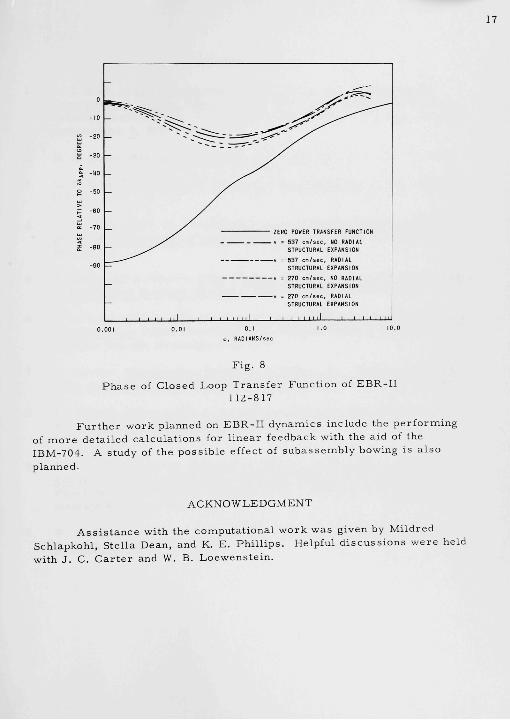
8 Phase of Closed Loop Transfer Function of EBR-II . . . . . . 17
LIST OF TABLES
No. Title Page
I EBR-II Reactivity Coefficients for Isothermal Expansion •
II Amplitude of Reactivity Feedback of EBR-II at Full Power
14
15
III Phase Lag in Degrees of Reactivity Feedback of EBR-II Relative to Power • • 15


STABILITY ANALYSIS OF EBR-II
by
H. H. Hummel and L. T. Bryant
ABSTRACT
Calculations have been made for predicting the r e s o nance of EBR-II to oscillator measurements to be made during s tar tup of the reactor . Because of assumptions made in the calculations, which a re believed to be justified bythe design of the reactor , the only feedbacks are prompt negative ones. No instability in the calculated behavior is therefore possible.
The radially lumped pin model gives good resul ts for EBR-II pins for frequencies up to 2 to 3 radians per second because of the short pin time constant, of the order of 0.1 sec.
1. ASSUMPTIONS AND CALCULATIONS
Calculations have been made for predicting the behavior of EBR-II during oscillator measurements to be made during startup of the reactor . Because of assumptions made in the calculations, which are believed to be justified by the design of the reactor , no instability in its operation appears possible.
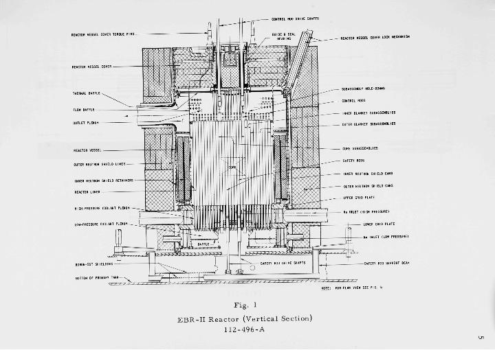
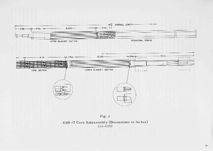
The design of EBR-II has been discussed in detail elsewhere.(1) A vert ical section of the reactor is shown in Fig. 1. A drawing of the core subassemblies is shown in Fig. 2. The core region of a normal subassembly contains 91 pins each 14.22 in. long. The fuel is uranium metal approximately 50% enriched in U"^ and containing 5 wt-% simulated fission products (this alloy is refer red to as fissium). The fuel pins a re 0.144 in. in diameter and are surrounded by a sodium bond, 6 mils thick, and a Type 304 stainless steel clad, 9 mils thick. The upper and lower blankets contain similar but larger pins, 19 to a subassembly, the uranium diameter being 0.317 in. in this case. Above and below the core a re coolant header regions in which sodium is redistr ibuted between core and blanket pins.
The following description of the subassemblies and their method of support has been reproduced from Ref. 3.

REACTOR VESSEL COVER TOHOOE P I N S -
REACTOR VESSEL COVER -
THERMAL BAFFLE ^
CONTROL ROD DRIVE SHAFTS
OUTLET PLENUM -
REACTOR VESSEL -
OUTER NEUTRON SHIELD L I N E R -
INNER NEUTRON SHIELD R E T A I N E R S -
REACTOR LINER
HIGH-PflESSURE COOLANT PLENUM -
LOW-PRESSURE COOLANT PLENUM^
BOROH'SST SHIELDIN
BOTTOM OF PRIMARY 1
-REACTOR VESSEL COVER LOCK MECHAN1SH
- SUBASSEMBLY HOLD-OOHHS
CONTROL RODS
' INNER BLANKET SUBASSEMBLIES
- OUTER BLANKET SUBASSEMBLIES
- CORE SUBASSEMBLIES
SAFETY RODS
INNER NEUTRON SHIELD CANS
OUTER NEUTRON SHIELD CANS
- UPPER GRID PLATE
Na INLET (HIGH PRESSURE)
LOWER GRID PLATE
- H > INLET (LOW PRESSURE)
-SAFETY ROD SUPPORT BEAM
MOTE: FOR PLAN VIEW SEE F I G .
Fig. 1
EBR-II Reactor (Vertical Section) 112-496-A

UPPER BLANKET SECTION HEXAGONAL TUBING
Fig. 2
EBR-II Core Subassembly (Dimensions in Inches) 111-5157


"All core subassemblies a re identical in size and shape (hexagonal). The dimension ac ross outside flats of each subassembly is 2.290 in. The center - to-center spacing of the subassembl ies is 2.320 in. The resulting nominal clearance between flats of adjacent subassemblies is 0.030 in. Each core subassembly, as well as each inner blanket subassembly, is provided with a "button" on each of its six flats; the buttons a re positioned so that they lie in a horizontal plane 1.00 in. above the core (fuel) center line. These buttons protrude a nominal 0.014 in. from the subassembly flat. The button flats a re 0.375 in. in diameter. The dimension ac ross opposite button flats of each subassembly is held to 2.318 ± 0.002 in. The resulting nominal clearance between button flats of adjacent subassemblies is 0.002 in.
"The subassemblies a re positioned and supported in the reactor by their lower adaptors, the ends of which pass through holes in the upper plate of the support grid and engage in the axially aligned holes in the lower plate. The portion of the adaptor which res t s on the upper plate is of the shape of a truncated sphere; the upper edge of the plate hole, on which the adaptor r e s t s , is chamfered conically. This arrangement provides a continuous line contact for subassembly support. It has been established experimentally that la tera l movement of the upper part of the subassembly (or of the lower end of the adaptor) is accommodated by pivoting of the subassembly about this area of contact; that is, lateral movement of the subassembly in the region of contact with the upper plate does not occur unless a very large force is applied. The reason for this is that the latter movement can take place only in accompaniment with an upward shifting of the entire subassembly, due to the conical shape of the support seat. Consequently, application of la teral force m or above the region of the core section produces only a pivoting of the subassembly until the lower end of the adaptor closes the lower plate hole clearance (0.0042 in. radially), and, thereafter, resul ts in bending of the subassembly. Lateral movement of the top end is unrestr icted up to nominal displacement of 0.030 in., when contact with the adjacent subassembly is made; if the adjacent subassembly also undergoes displacement, restr ict ion is not effected until after correspondingly greater displacement."
Two vital factors affecting the safety of a fast reactor , which are both dependent in its specific design, a re bowing of the fuel elements and the presence of a large delayed negative reactivity coefficient.i^) Such a delayed coefficient would be expected to be caused by expansion of an upper supporting s t ructure and result in outward movement of the fuel. Because of the method of bottom support of the EBR-II subassemblies, it is assumed that no such effect takes place. The question of bowing in EBR-II has been discussed in Ref. 3. This matter is currently under reconsideration, but
no bowing effects have yet been incorporated into the feedback model. It is not believed that these effects will prove to be significantly large. There is some question about how large the radial c learances between subassemblies will actually be. It is believed that under operating conditions probably no clearances will exist and that the core will expand radially according to the local subassembly wall tempera ture , assumed to be the same as the local coolant tempera ture . The calculations have been performed with and without the radial expansion feedbacks to i l lustrate the magnitude of the effect involved.
There a re adequate experimental and theoretical resul ts to indicate that the Doppler effect will be insignificant in EBR-II, and it has therefore been ignored. The sodium void coefficient, which has been found to be positive in certain large reactors , (4 , 5) is strongly negative in EBR-II.
Because of the large sodium inventory in the pr imary coolant tank, the temperature of the sodium entering the reactor has been assumed to be constant.
Because of the above assumptions, no prompt positive or delayed negative reactivity coefficients are present in the feedback model, and the predicted behavior is therefore quite stable. The assumed feedback is a prompt negative one due to unrestrained thermal expansion of fuel and steel and to coolant expansion.
No non-l ineari t ies a re present in the feedback model used so far. Limited bowing would be one possible source of non-linearity. Another possible source of non-l ineari t ies is phase transformation in the fuel. It is believed, however, that this will be too sluggish in the case of fissium to affect the resul t s of oscillator experiments.
2. TEMPERATURE CALCULATIONS
Oscillating temperatures in the EBR-II fuel pins have been calculated both with an IBM-704 code prepared for Long,(6) by means of the exact integration technique of Storrer,(V) and with an analog computer. These calculations were made for two-region pins, the inner region being the metallic fuel and the outer, the homogenized sodium bond and steel clad. Although the digital computer technique is more accurate , its application is limited to linear problems in which time dependence can be separated out. Use of the analog is desirable because it permits study of the effect of non-linear feedbacks (although none has so far been assumed in EBR-Il) and of non-linearity in the kinetics equation.

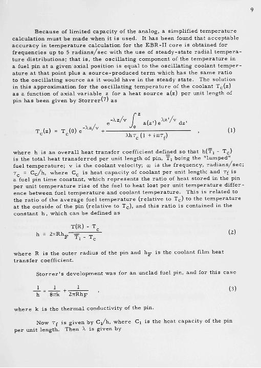
B e c a u s e of l i m i t e d c a p a c i t y of the a n a l o g , a s imp l i f i ed t e m p e r a t u r e c a l c u l a t i o n m u s t be m a d e when it i s u sed . It h a s b e e n found tha t a c c e p t a b l e a c c u r a c y in t e m p e r a t u r e c a l c u l a t i o n for the E B R - I I c o r e is ob ta ined for f r e q u e n c i e s up to 5 r a d i a n s / s e c wi th the u s e of s t e a d y - s t a t e r a d i a l t e m p e r a t u r e d i s t r i b u t i o n s ; tha t i s , the o s c i l l a t i n g c o m p o n e n t of the t e m p e r a t u r e in a fuel pin a t a g iven a x i a l p o s i t i o n is e q u a l to the o s c i l l a t i n g coo lan t t e m p e r a t u r e a t tha t point p lus a s o u r c e - p r o d u c e d t e r m which h a s the s a m e r a t i o to the o s c i l l a t i n g s o u r c e a s it would have in the s t e a d y s t a t e . The so lu t ion in th i s a p p r o x i m a t i o n for the o s c i l l a t i n g t e m p e r a t u r e of the coo lan t Tc(z) a s a funct ion of a x i a l v a r i a b l e z for a hea t s o u r c e a(z) pe r unit l eng th of pin h a s b e e n g iven by S t o r r e r W / a s
, e - ^ " / " / a ( z ' ) e ^ " ' / " d z '
T , ( z ) = T^(0) e - ^ ^ / ^ + , , , , . , . (1) ^ <= XhT ( l + ICDT )
c ^ f
w h e r e h is an o v e r a l l hea t t r a n s f e r coeff ic ient defined so tha t h(Ti - T^) is the t o t a l h e a t t r a n s f e r r e d pe r uni t l eng th of pin, Tj be ing the " l u m p e d " fuel t e m p e r a t u r e ; v i s the coo lan t ve loc i ty ; tu i s the f r equency , r a d i a n s / s e c ; T = C c / h , w h e r e C , i s hea t c a p a c i t y of coolan t pe r unit length; and Tf i s a fuel pin t i m e cons t an t , wh ich r e p r e s e n t s the r a t i o of hea t s t o r e d in the pin p e r unit t e m p e r a t u r e r i s e of the fuel to hea t lo s t pe r unit t e m p e r a t u r e d i f f e r e n c e b e t w e e n fuel t e m p e r a t u r e and coolan t t e m p e r a t u r e . This i s r e l a t e d to the r a t i o of the a v e r a g e fuel t e m p e r a t u r e ( r e l a t i v e to Tc) to the t e m p e r a t u r e a t the o u t s i d e of the pin ( r e l a t i v e to T,-), and th i s r a t i o i s con ta ined in the c o n s t a n t h , wh ich can be defined a s
h = 27TRh
T(R) - T^
F Tj (2)
w h e r e R is the o u t e r r a d i u s of the pin and h-^ i s the coo lan t f i lm hea t t r a n s f e r coef f ic ien t .
S t o r r e r ' s d e v e l o p m e n t was for an unc lad fuel pin, and for t h i s c a s e
- l = - i - + ' , (3) h 87Tk ZTrRhj-
w h e r e k i s the t h e r m a l conduc t iv i ty of the pin.
Now T£ i s g iven by C ] / h , w h e r e Cj is the hea t c a p a c i t y of the pin
p e r uni t l eng th . Then X i s g iven by

X = , , 2 2 1 + 00 T ,
CD + 1 I 1 + + T,. CD ^ C ^ ^C
f (4)
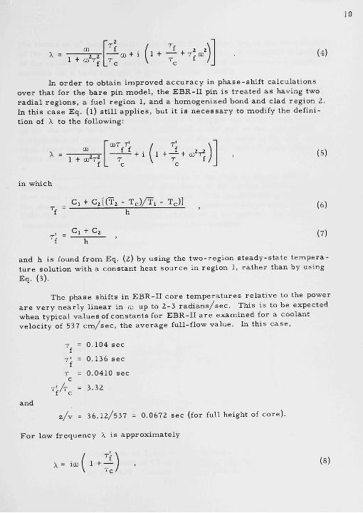
In o r d e r to ob ta in i m p r o v e d a c c u r a c y in p h a s e - s h i f t c a l c u l a t i o n s over that for the b a r e pin m o d e l , the EBR-II pin is t r e a t e d a s having two r a d i a l r e g i o n s , a fuel r e g i o n 1, and a h o m o g e n i z e d bond and c lad r e g i o n 2. In th i s c a s e Eq. ( l ) s t i l l a p p l i e s , but it i s n e c e s s a r y to modify the de f in i t ion of X to the fol lowing:
10
X = 1 -I- toVJ
CDT T ' / T
-^-^ + i 1 + — + C D V T V T f
C C
(5)
in wh ich
Ci + C2[(T2 - T C ) / T I - Tc)] (6)
Ci + Cz (7)
and h is found f r o m Eq. (2) by us ing the t w o - r e g i o n s t e a d y - s t a t e t e m p e r a t u r e so lu t ion wi th a c o n s t a n t hea t s o u r c e in r e g i o n 1, r a t h e r than by us ing Eq. (3).
The p h a s e shi f ts in E B R - I I c o r e t e m p e r a t u r e s r e l a t i v e to the power a r e v e r y n e a r l y l i n e a r in cD up to 2 -3 r a d i a n s / s e c . This i s to be e x p e c t e d when t y p i c a l v a l u e s of c o n s t a n t s for E B R - I I a r e e x a m i n e d for a coo lan t v e l o c i t y of 537 c m / s e c , the a v e r a g e ful l - f low v a l u e . In th i s c a s e ,
T = 0.104 s e c f
T ' = 0.136 s e c
r ' / i
T = 0.0410 s e c c
= 3.32
and
z / v = 3 6 . 1 2 / 5 3 7 = 0.0672 s ec (for full he igh t of c o r e )
F o r low f r e q u e n c y X is a p p r o x i m a t e l y
X = lO) 1 +• (8)


11
the t e rms in tu being small. The coolant t ransport lag in the core is then of the order of [ l -I- {T'^/T )] z/v, which is 0.29 sec. A complete discussion of the validity of lumped parameter models and of low-frequency approximations for a bare fuel pin is given in Refs. 7 and 8.
The application of the bare pin approximation, using Eq. (3) for h and the definition of T according to Eq. (7), leads to a value of Tf of 0.087 sec. This would not make X significantly different from the value given by Eq. (5) at low frequency, since h divides out of the te rm linear in CD. An e r ro r of 20% would be produced in the part of the phase shift independent of coolant velocity because of the icDTf term in Eq. (l). It has been found that Eq. (l) with the use of Eqs. (5), (6), and (7) gives phase shifts very accurately in the low-frequency range.
Solutions for coolant temperature in the core by means of the radially lumped model have been obtained with the analog computer, using four axial segments in the core. Equation (l) is the continuous solution for this case. This is compared with the rigorous solution from the IBM-704 in Figs. 3 to 6. Although agreement is not perfect, the analog computation is seen to be a reasonable approximation.
u = I radian/sec /
V
y^
/ X
/ /
u = E radians/sec
y
Fig. 3
Amplitude of Tc(z) in EBR-II Core in °C for Oscillations of 1% of Full Power Multiplied by 270/537. Coolant Velocity 270 cm/sec
112-812


12
0
-10
-20
-30
-HO
-50
-60
-7C
-BO
-00
_
-
-
-
^^__^
\
"
u = 1
\
u> = 5 radians/sec
ad i an/sec
_ ~ ^ ^ _ _ _
V
N
\ N,
Fig. 4
Phase of Tc(z) in EBR-II Core Relative to Power. Coolant Velocity 270 c m / s e c
112-809
Fig. 5
Amplitude of Tc(z) in EBR-II Core in °C for Oscillations of 1% of Full Power. Coolant Velocity 537 cna/sec.
112-811

13
0
-10
-20
-30
^ -HO
^ -50
o
S -co
-70
-80
-90
-
-
(J = 1
1 ^ _ . ^ _
radian/sec
(ll = 5 radl ans/sec
—.^_- -^^_
~ ^
F i g . 6
P h a s e of Tc(z) in E B R - I I C o r e R e l a t i v e to P o w e r . Coolant Ve loc i ty 537 c m / s e c .
112-810
The p r o b l e m of ca l cu l a t i ng l a r g e t e m p e r a t u r e p h a s e and a m p l i t u d e c h a n g e s which can o c c u r b e t w e e n the r e a c t o r c o r e and an upper s u p p o r t ing s t r u c t u r e can be an i m p o r t a n t one for r e a c t o r s t ab i l i t y . It has b e e n found to be so in s t u d i e s of E B R - I , M a r k II.v9) The r a d i a l l y l umped p a r a m e t e r m o d e l i s p r o b a b l y of l i m i t e d u s e f u l n e s s in a t t a ck ing th i s p r o b l e m . In th i s c a s e , s i n c e t h e r e i s no s o u r c e ^ the s t e a d y - s t a t e t e m p e r a t u r e d i s t r i b u t i o n i s a c o n s t a n t , so tha t Tj = Tj = T ( R ) .
The t e r m l/STik in Eq . (3) would not apply in the c a s e of a o n e - r e g i o n pin wi th no hea t s o u r c e . F o r fas t r e a c t o r s the f r equency r a n g e of g r e a t e s t i n t e r e s t for s t a b i l i t y i s be low ~1 r a d i a n / s e c . In th i s f r equency r a n g e , if hea t t r a n s f e r i s f r o m the coo lan t to r e l a t i v e l y th in p i e c e s of m e t a l , a m p l i tude a t t e n u a t i o n can p r o b a b l y be n e g l e c t e d and the p h a s e c a l c u l a t e d f rom
X = icD 1 + "M (9)

14
where Cj^ is the heat capacity of the metal per unit length. This is equivalent to assuming that metal and coolant at a given z a re instantaneously at the same temperature . This assumption was made in this paper in dealing with the coolant header gap regions immediately above and below the EBR-II core. If heat transfer is to thick pieces of metal or to mater ia l of low thermal conductivity, the lumped parameter model probably cannot be used at all, as temperature phase shifts in the solid mater ia l and amplitude attenuation will be large, even at low frequency. In this case, the exact solution of Storrer^' . ' must be employed.
3. REACTIVITY COEFFICIENTS, OPEN AND CLOSED LOOP TRANSFER FUNCTIONS
Calculations of transfer functions have been carr ied out so far only on the analog. Core temperatures have been calculated for a single r e p r e sentative pin, whereas coolant gaps and blankets have been lumped both radially and axially. The reactivity coefficients of expansion of fuel, steel, and sodium were obtained from mater ia l replacement measurements in ZPR-III on an EBR-II mockup. ' l ' ' ) These reactivity coefficients are given in Table I for a core divided into eight axial slices, which were lumped into four slices for the feedback calculations.
Table I
EBR-n REACTIVITY COEFFICIENTS FOR ISOTHERMAL E X P A N S I O N I ' I
f-|^« io5/"c)
C o r e - A z , cm
(from bottom)
0- 4.52
4.52- 9.03
9.03-13.55
13.55-18.06
18.06-22.58
22,58-27.09
27.09-31.61
31.61-36.12
Core Total
Gap, Unlagqed Gap.tjggedtc)
Upper Blanket
Radial Blanket
Axial
Expans
Fuel
0,017
0,060
0.086
0,100
0,098
0,080
0,059
0,027
0,527
0,016
0,104
i
ion
Steel
0,008
O006
0,004
0,003
0,003
0,004
0,006
0,008
0,042
0.008
0,005
0,004
0,051
Assumed coefficients of expansion
Coolant
Expansion
0135
0115
0,108
O lO l
0,101
0,108
0,115
0,135
0918
0,157
0115
0.103
0.128
- Sodium Volume
Steel Linear
Fuel Linear
Dispiacement'ti*
by Steel
Expansion
O017
0,015
0,014
0013
O013
0,014
0015
0,017
0.118
0,013
0,066
2,9 X W'^IK
1,9 X 10⁻⁵/<>C
1,8 X 10"5/"C
Radi; ii Structural
Expansion
Fuel
0,100
0,142
0,157
0174
0,168
0-141
0,125
0,087
1,094
0,032
0,216
Steel
O019
0,013
O0O9
0,006
0,006
0,009
0,013
0,019
0,094
0,054
0,008
0,102
All expansions except axial fuel assumed proportional to local coolant temperature,
' ' ' ' i h i s effect is cancelled if radial s t ructure expansion occurs,
' '^'lag is 0.24 sec at f u l l flow of 537 cm/sec and is inversely proportional to
coolant velocity.


15
The lack of symmetry of fuel worth about the core midplane found in the measurements is presumably due to a similar dissymmetry in EBR-II geometry. The coefficients are divided into those which are based on no radial expansion and those which are associated with unrestrained radial expansion. Lumped coefficients a re given for the upper coolant gap, upper blanket, and the radial blanket. The unlagged and lagged components of the gap feedback and the lag time were obtained from use of the temperature variation through the gap obtained as described above.
The amplitudes and phases of the reactivity feedbacks relative to the power are given in Tables II and III. Feedback for the radial blanket was found to be negligible above CD = 0.1 rad ian/sec . Large axial phase shifts a re expected to occur in this case because of the low coolant flow ra te . A more refined treatment is clearly desirable here.
Table I
AMPLITUDE OF REACTIVITY FEEOBACK OF EBR-n AT FULL POWER
» • 270 cmlsec » • 537 cmfsec
No Radial Expansion Radial Expansion No Radial Expansion
Frequency w radians/sec
Feedback, SWfi / ISn/nol
Na in Core
U in Core
Total Core
Upper Gap (Unlagged)
Upper Gap (Laggedllal
Upper Blanket
Radial Blanket
Total
0,1 1,0 2,5 5,0 0,1 1,0 2,5 5,0 01 1,0 2.5 5,0 0,1 1,0 2,5 5,0
0391 0,377 0322 0,211 0,200 0192 0,164 0112 0,219 0,214 0197 0156 0,111 OllO OlOl O080
0,164 0.158 0,132 0,087 0164 0,159 0,132 0,087 0,117 0,115 0,104 0,078 0,115 0,114 0,104 0,079
0,555 0534 0,455 O308 0,362 0,350 0,297 0199 0,336 0330 0,300 0,236 0229 0,224 0,205 0159
0,0f 0,077 O062 O037 0,060 0057 O047 O028 0,0 0,047 O042 O031 0,036 O035 0,031 O023
O042 O039 O032 O018 O042 0,041 0,032 O018 0,024 0,024 0,021 0,015 0,024 0,024 0,021
0,059 0,050 0,035 O017 0,049 O043 0,029 O015 0035 0031 0026 O016 0029 O025 O021 O014
0.033 - - - 0,013 - - - 0,021 - - - 0,009 -
0.760 0,689 0530 0,312 0523 0478 0,354 0195 0,460 0,430 0378 0274 0,325 0.308 0.267 0184
(al, Lag is 0.48 sec at 270 cm/sec, 0,24 sec at 537 cm/sec coolant velocity.
Table m
PHASE U G IN DEGREES OF REACTIVITY FEEDBACK OF EBR-H RELATIVE TO POI»ER
Frequency w, radians/sec
Feedback Phase
Na in Core
U in Core
Total Core
GaplUnlaggedl
Gap(L^gged)
Upper Blanket
Radial Blanket
Total
01
1,8
1,4
1,8
2.3
5,5
3,8
47,3
4,1
Radial Expansion
1.0
17,3
17,4
17,4
22,7
48,9
58,7
22,9
2,5
40,1
39,8
40,1
52,6
120,7
131,5
48,9
V = 270 cm/sec
5,0
65,4
63,0
647
84,8
2135
230,4
69,9
No Radial Expansion
01
1,9
1,5
1.8
2,4
3,4
6,1
46,4
3,4
1,0
17,7
17,6
17,5
22,9
49,3
60,8
24,4
2,5
40,7
40,0
40,3
52,4
121,6
133,3
-51,5
5,0
66,2
62.6
64,8
84.3
2211
235,1
701
1
01
1.2
1,3
1,2
1,0
3.8
3.8
28,8
2,4
Radial Expansion
1,0
12,0
12,2
12,2
15,1
27,9
36,7
• 13.9
2,5
28,7
29,1
28,9
35.1
69,6
82.2
-34,9
V . 537 cm)sec
5,0
504
50,5
504
61,6
135,0
141,2
-58,5
No Radial Expansic
0 1 1,0 2,5
1,1
1,1
1,3
1,3
1.8
43
28,4
2.5
11,9
12,3
12,3
13,6
30,4
37.9
15.8
29,0
29,3
29,1
35,3
69,8
79,1
36,3
)n
5,0
51,2
39,9
50,6
61,4
139,1
-60,5

16
The 537-cm/sec case corresponds to average full flow in the core. Amplitudes for both velocities a re given as (6kFB/|3)/{6n/no), where 6kpB//3 is the amplitude in dollars of the oscillating reactivity feedback for oscillation at full power, and 6n/no is the fractional change in power. In calculating the closed loop transfer function at reduced power, which would be necessa ry at reduced flow, the amplitudes in Table II are to be multiplied by the fraction of full power at which the reactor operates.
In Figs. 7 and 8, the EBR-II closed loop transfer function phase and amplitude are given for the various assumptions made in the feedback. The amplitude in this case is (6n/no)/(6k^pp//3), where S k ^ p p / p is the applied oscillating reactivity in dollars. The phase is that of the power relative to the applied reactivity. As expected, there is no indication of the formation of a resonance.
3
2
1
0
9
8
7
B
5
U
3
2
1
0
\ \ Vc = 537, NO RADIAL STRUCTURAL
_ \ EXPANSION
\ Vc = 537 . RADIAL STRUCTURAL \ EXPANSION
\ Vc = 270 , NO RADIAL STRUCTURAL _ \ EXPANSION
\ Vc = 270 , RADIAL STRUCTURAL \ EXPANSION \ 7Efin P"WFP TP^HSFF" c^ i^T in i !
\ \ \
\
1 1 i , , IL^. I ^
Fig. 7
Amplitude of Closed Loop Transfer Function of EBR-II. Curves for v = 537 cm/sec for Full Power. Curves for v = 270 cm/sec for Full Power x 270/537.
112-815

17
Fig. 8
Phase of Closed Loop Transfer Function of EBR-II 112-817
Further work planned on EBR-II dynamics include the performing of more detailed calculations for linear feedback with the aid of the IBM-704. A study of the possible effect of subassembly bowing is also planned.
ACKNOWLEDGMENT
Assistance with the computational work was given by Mildred Schlapkohl, Stella Dean, and K. E. Phillips. Helpful discussions were held with J. C. Car ter and W. B. Loewenstein.


REFERENCES
1. L. J. Koch et al_., Construction Design of EBR-II: An Integrated, Unmoderated Nuclear Power Plant, Proceedings of the Second International Conference for the Peaceful Uses of Atomic Energy, Geneva, Switzerland, _9.. 323 (1958).
2. H. A. Bethe, Reactor Safety and Oscillator Tests , APDA-117 (1956).
3. L. J. Koch et aL, Hazards Summary Report for EBR-II, ANL-5719 (1957).
4. J. B. Nims and P. F. Zweifel, Prelinainary Report on Sodium Tempera ture Coefficients in Large Fast Reactors , APDA-135 (Novem-ber 1959).
5. S. Yiftah and D. Okrent, Some Physics Calculations on the Performance of Large Fas t Breeder Reactors , ANL-6212 (December I960).
6. J. K. Long and Ray Haroldsen, Analysis of EBR-I Power Temperature Relationships, Paper Presented at Washington Meeting of American Nuclear Society, November 4-6, 1959.
7. F. S tor re r , Temperature Response to Power, Inlet Coolant Temperature , and Flow Transients in Solid Fuel Reactors , APDA-132 (1959).
8. F. S tor rer , Proceedings of the Conference on Transfer Function Measurement and Reactor Stability Analysis, ANL-6205, (May 2-3, I960) p. 251.
9. R. R. Smith et al. . An Analysis of the Stability of EBR-I, Mark I, II, and III, and Conclusions Pert inent to the Design of Fast Reactors , Paper presented at IAEA Seminar on the Physics of Fast and Intermediate Reactors , Vienna (1961).
10. W. P . Keeney and J. K. Long, Idaho Division Summary Report, July-September, I960, ANL-6301.