Stabilisation of Beams by Sandwich Panels – New ... · Stabilisation of Beams by Sandwich Panels...
13
Stabilisation of Beams by Sandwich Panels – New Regulations and Recent Research Results Misiek, T. Karlsruhe Institute of Technology, Karlsruhe, Germany (email: [email protected]) Käpplein, S. Karlsruhe Institute of Technology, Karlsruhe, Germany (email: [email protected]) Dürr, M. Montana Bausysteme AG, Villmergen, Switzerland (email: [email protected] Saal, H. Karlsruhe Institute of Technology, Karlsruhe, Germany (email: [email protected]) Abstract Sandwich panels are modern pre-fabricated construction components used as cladding elements for different types of buildings. Sandwich panels consist of an insulating core material covered by two faces which are typically made of thin metal sheets. In standard applications, the panels are mounted and fixed on a load-bearing substructure of beams or purlins. Sandwich panels can reduce the problem of lateral torsional buckling of this substructure of beams or purlins by providing stabilization either by shear stiffness or by torsional restraint. The new edition of the German standard for the design of steel structures DIN 18800 gives formulae for the calculation of the stiffness of the torsional spring for restraint of the substructure under vertical downward loading. These new regulations are based on experimental investigations and parametric finite element analyses. These formulae only apply for sandwich panels with steel facings and polyurethane and mineral wool as core material. The paper explains the load-bearing mechanisms of the stabilisation effect by the sandwich panel. A mechanical model is developed for extending the range of application of the design formulae and to include the effects of creep and elevated ambient temperature. It presents the new regulations of DIN 18800 and explains the tests on which these regulations are based.The spectrum of applications not yet examined is investigated by tests and accompanying numerical calculations within the framework of the EASIE project. As a result of these investigations the torsional restraint of panels with facings made of aluminium and glass fibre reinforced plastics (GFRP) and with cores made of EPS are dealt with. The load case wind suction is discussed in addition. The increase of the torsional restraint obtained by fixing roof panels at the upper flange (which is mainly with saddle washers) is also explained and quantified by these investigations. Keywords: sandwich panels, lateral-torsional buckling, torsional restraint 1
Transcript of Stabilisation of Beams by Sandwich Panels – New ... · Stabilisation of Beams by Sandwich Panels...
Stabilisation of Beams by Sandwich Panels – New Regulations and Recent Research Results
Misiek, T. Karlsruhe Institute of Technology, Karlsruhe, Germany
(email: [email protected]) Käpplein, S.
Karlsruhe Institute of Technology, Karlsruhe, Germany (email: [email protected])
Dürr, M. Montana Bausysteme AG, Villmergen, Switzerland
(email: [email protected] Saal, H.
Karlsruhe Institute of Technology, Karlsruhe, Germany (email: [email protected])
Abstract
Sandwich panels are modern pre-fabricated construction components used as cladding elements for different types of buildings. Sandwich panels consist of an insulating core material covered by two faces which are typically made of thin metal sheets. In standard applications, the panels are mounted and fixed on a load-bearing substructure of beams or purlins. Sandwich panels can reduce the problem of lateral torsional buckling of this substructure of beams or purlins by providing stabilization either by shear stiffness or by torsional restraint. The new edition of the German standard for the design of steel structures DIN 18800 gives formulae for the calculation of the stiffness of the torsional spring for restraint of the substructure under vertical downward loading. These new regulations are based on experimental investigations and parametric finite element analyses. These formulae only apply for sandwich panels with steel facings and polyurethane and mineral wool as core material. The paper explains the load-bearing mechanisms of the stabilisation effect by the sandwich panel. A mechanical model is developed for extending the range of application of the design formulae and to include the effects of creep and elevated ambient temperature. It presents the new regulations of DIN 18800 and explains the tests on which these regulations are based.The spectrum of applications not yet examined is investigated by tests and accompanying numerical calculations within the framework of the EASIE project. As a result of these investigations the torsional restraint of panels with facings made of aluminium and glass fibre reinforced plastics (GFRP) and with cores made of EPS are dealt with. The load case wind suction is discussed in addition. The increase of the torsional restraint obtained by fixing roof panels at the upper flange (which is mainly with saddle washers) is also explained and quantified by these investigations.
Keywords: sandwich panels, lateral-torsional buckling, torsional restraint
1
1. Stabilising effects on beams
Sandwich panels increase the resistance of substructures (beams, purlins) against lateral torsional buckling by restraining the lateral displacements and rotations.
The high in-plane shear stiffness of sandwich panels can be used for stabilizing the lateral displacement of the substructure and thus preventing lateral torsional buckling of the substructure. This type of stabilization requires the exact knowledge of the in-plane shear stiffness. Special considerations are necessary for the design of the fastenings because the flexibility of the connection to the substructure and that of neighbouring panels to each other reduces the effective shear stiffness significantly.
The torsional restraint is governed by the stiffness of the connection of the sandwich panel to the substructure. Recent research carried out by Dürr (2008) showed that this stiffness significantly depends on the load transferred by the sandwich panel to the substructure. Dürr (2009) gives formulae for calculating the parameters of this moment-rotation-relation for sandwich panels under deadweight loading and with two different core materials. So far only connections through the lower flange of the outer face with two fasteners per element have been investigated. Other types of connections (e.g. connection through upper flange of the outer face with saddle washers) and different core materials are important yet unknown parameters of the moment-rotation-relation.
The focus of the present paper is on the stabilisation of beams by torsional restraint.
2. General description of the effects
2.1 The spring stiffnesses
The torsional restraint by sandwich panels can be calculated by using the mechanical model of a torsion spring with the spring stiffness c . This spring stiffness is a combination of the bending stiffness of the attached panel c C, the stiffness of the connection c A and the distortional stiffness c B of the beam to be stabilised. The stiffnesses c C and c B depend on the geometry of the sandwich panels and type of beams used. They can be easily calculated. We will focus on the stiffness c A of the connection between the sandwich panel and the subjacent beam because this is the weak link dominating the value of the combined stiffness c of the chain of springs. In the following text, the stiffness c A will be simply denoted as c to ease reading and to reduce the number of subscripts.
2
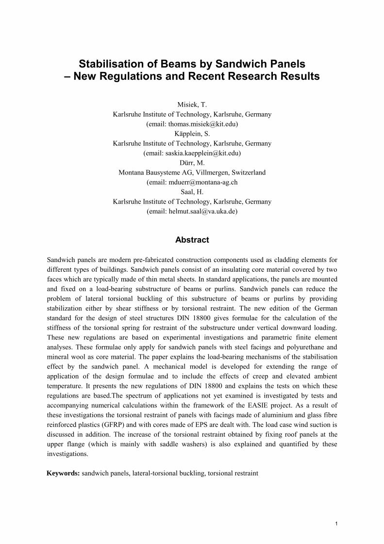
c
Figure 1: Stabilisation: torsional restraint
2.2 Sandwich panels with deadweight loading
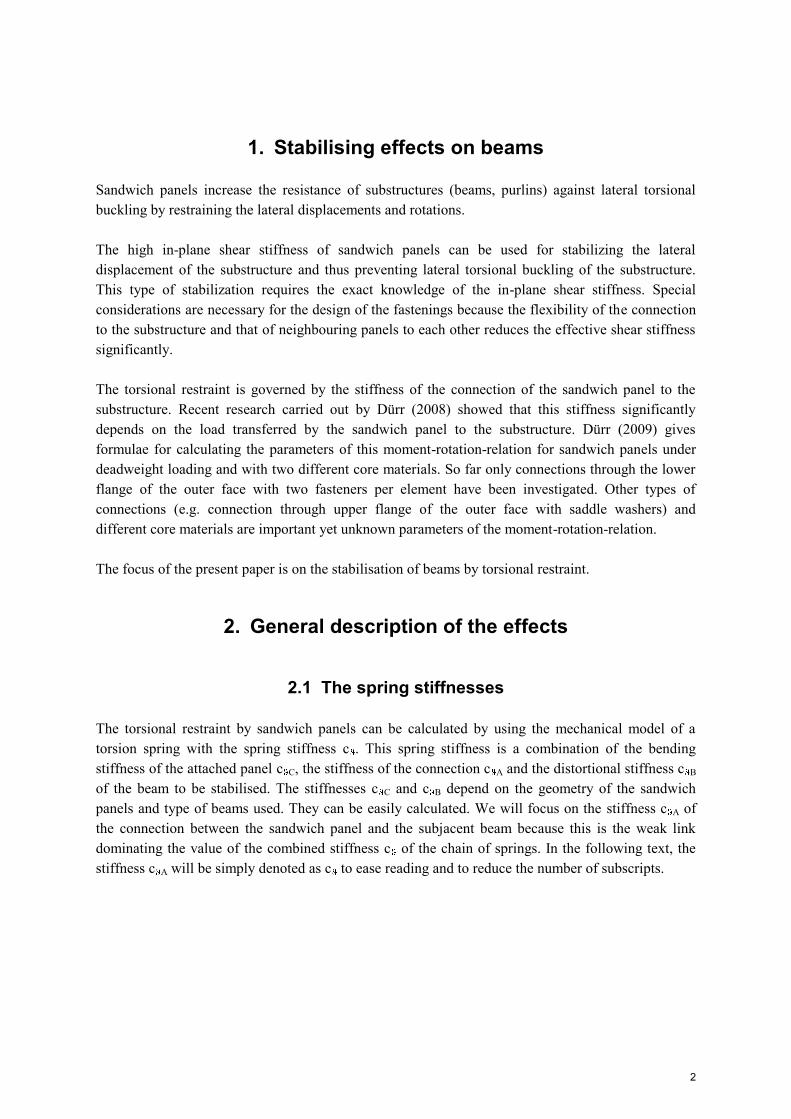
Figure 2 shows a generalised moment-rotation-relation for the spring stiffness of the connection of a sandwich panel under deadweight loading.
c 1
c 1
c 2
m
mK
mKc 2 0
Figure 2: Generalised moment-rotation-relation for deadweight loading
In this generalised relation we assume that all of the fasteners are mounted on one side of the web as shown in Figure 2. Here, the positive direction of rotation is defined as an anticlockwise rotation.
We can differentiate three parts of the moment-rotation-relation. For small rotations , there is the value c 1. The load q acting on the panel is always transferred by contact from the inner face of the panel to the upper flange of the beam. The rotational stiffness only depends on the width of the flange and the indentation stiffness (Figure 3). This indentation stiffness is dominated by the compression stiffness ECc of the core material. The rotational stiffness does not depend on the position of the fasteners because the fasteners are not activated in this situation.
3
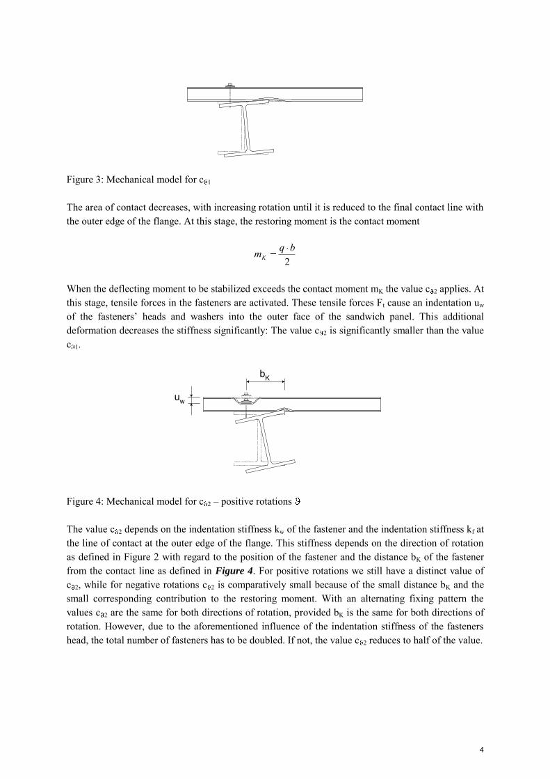
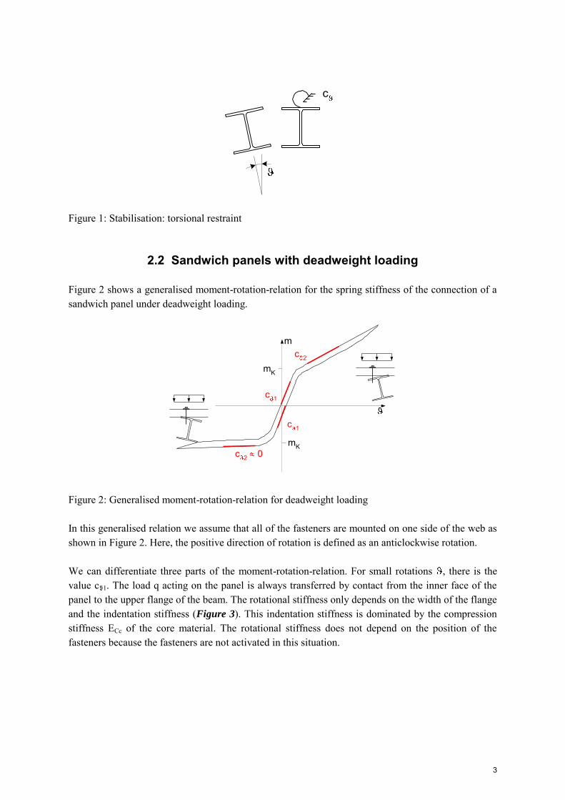
Figure 3: Mechanical model for c 1
The area of contact decreases, with increasing rotation until it is reduced to the final contact line with the outer edge of the flange. At this stage, the restoring moment is the contact moment
2bqmK
When the deflecting moment to be stabilized exceeds the contact moment mK the value c 2 applies. At this stage, tensile forces in the fasteners are activated. These tensile forces Ft cause an indentation uw of the fasteners’ heads and washers into the outer face of the sandwich panel. This additional deformation decreases the stiffness significantly: The value c 2 is significantly smaller than the value c 1.
uw
bK
Figure 4: Mechanical model for c 2 – positive rotations
The value c 2 depends on the indentation stiffness kw of the fastener and the indentation stiffness kf at the line of contact at the outer edge of the flange. This stiffness depends on the direction of rotation as defined in Figure 2 with regard to the position of the fastener and the distance bK of the fastener from the contact line as defined in Figure 4. For positive rotations we still have a distinct value of c 2, while for negative rotations c 2 is comparatively small because of the small distance bK and the small corresponding contribution to the restoring moment. With an alternating fixing pattern the values c 2 are the same for both directions of rotation, provided bK is the same for both directions of rotation. However, due to the aforementioned influence of the indentation stiffness of the fasteners head, the total number of fasteners has to be doubled. If not, the value c 2 reduces to half of the value.
4
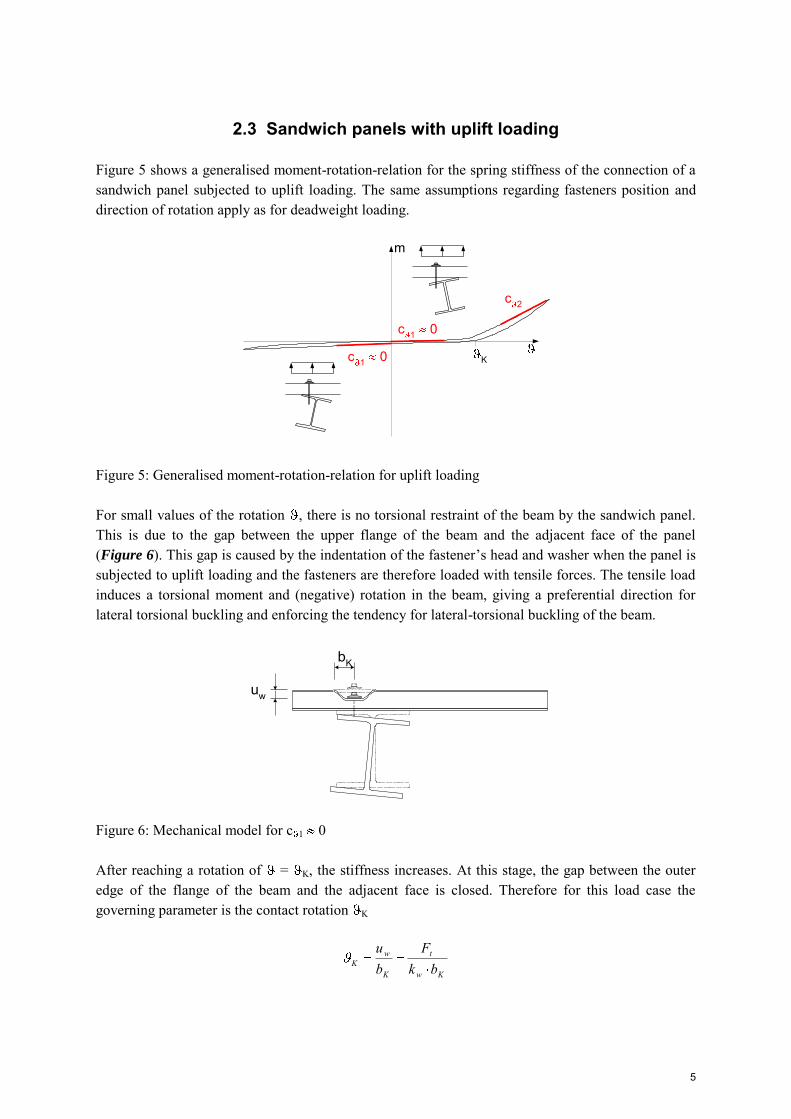
2.3 Sandwich panels with uplift loading
Figure 5 shows a generalised moment-rotation-relation for the spring stiffness of the connection of a sandwich panel subjected to uplift loading. The same assumptions regarding fasteners position and direction of rotation apply as for deadweight loading.
c 2
m
c 1 0
c 1 0 K
Figure 5: Generalised moment-rotation-relation for uplift loading
For small values of the rotation , there is no torsional restraint of the beam by the sandwich panel. This is due to the gap between the upper flange of the beam and the adjacent face of the panel (Figure 6). This gap is caused by the indentation of the fastener’s head and washer when the panel is subjected to uplift loading and the fasteners are therefore loaded with tensile forces. The tensile load induces a torsional moment and (negative) rotation in the beam, giving a preferential direction for lateral torsional buckling and enforcing the tendency for lateral-torsional buckling of the beam.
uw
bK
Figure 6: Mechanical model for c 1 0
After reaching a rotation of = K, the stiffness increases. At this stage, the gap between the outer edge of the flange of the beam and the adjacent face is closed. Therefore for this load case the governing parameter is the contact rotation K
Kw
t
K
wK bk
Fbu
5

with Ft being the tensile forces in the fasteners caused by the uplift loading and kw being the indentation stiffness of the fastener. For negative rotations , the rotational stiffness remains approximately zero because contact occurs only after very large rotations due to the small lever arm bK.
bK
uw
Figure 7: Mechanical model for c 2 0
A significant increase in stiffness can only be found for large positive rotations. Due to the direction induced by the tensile load in the fasteners this is a rather theoretical case. The mechanical model is the same as for deadweight loading (Figure 4), but with a different direction of rotation. In this case, the values c 2 are the same for uplift and deadweight loading but can not be taken into account. In practice, there is no torsional restraint with uplift loading for applications with all of the fasteners mounted on one side of the web. The use of an alternating fixing pattern is possible, too.
With an alternating fixing pattern the values c 2 are the same for both directions of rotation. However, due to the aforementioned influence of the indentation stiffness of the fasteners head, with the equal partitioning of the fasteners to both sides of the web c 2 reduces to half of its value. With the alternating fixing pattern the following disadvantage is avoided which occurs with the arrangement of the fasteners on one side of the web: The tensile forces in the fasteners resulting from the uplift loading induce a torsional moment enforcing the tendency for lateral-torsional buckling of the beam.
3. Regulations and standards: The new German design code
Most recently, the German design code for steel structures, DIN 18800-2, was updated, now including the possibility to use sandwich panels for the stabilisation of beams against lateral-torsional buckling. These regulations are based on the investigations described in Dürr (2008) which received financial support by the IFBS. The basic construction of the formulae (derivation of the influencing parameters) for c 1 and c 2 was derived from an FE-analysis whereas the parameters c1 and c2 were derived from a statistical evaluation of test results. These regulations are only given for downward loading and for the core materials PUR and mineral wool. Also, the parameter range for EC and tK is restricted.
A secant value of
6

K
K
mmc
can be taken into account, using the simplified moment-rotation relation shown in Figure 8. The necessary values and parameters are given in the following tables.
Figure 8: Moment-rotation-relation
Table 1: Values c 1 and c 2
Double-symmetric beams with 60 mm b 100 mm Z- or C-section with 60 mm b 80 mm
c 1 821bEc C CEc1
c 2 822btEc KC 0
mK 2bqd bqd
Table 2: Parameters
c1, c2 parameter according to
Table 3
2.0 N/mm² EC 6.0 N/mm² Young’s modulus of the core material
b [mm] width of the flange of the beam
0.42 mm tK 0.67 mm sheet thickness of the outer face layer
parameter depending on the pattern of fixings
= 1.0 alternating application of fixings
= 1.5 one-sided application of fixings
= 0.0 hidden fixings
qd design value of the downward load to be transferred from the panel to the beam
7
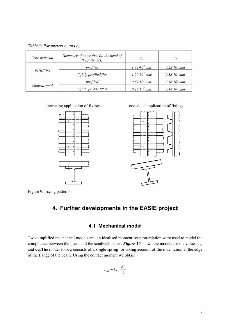
Table 3: Parameters c1 and c2
Core material Geometry of outer face (at the head of the fasteners) c1 c2
PUR/EPS profiled 1.44 103 mm² 0.22 103 mm
lightly profiled/flat 1.20 103 mm² 0.38 103 mm
Mineral wool profiled 0.69 103 mm² 0.18 103 mm
lightly profiled/flat 0.48 103 mm² 0.16 103 mm
alternating application of fixings one-sided application of fixings
Figure 9: Fixing patterns
4. Further developments in the EASIE project
4.1 Mechanical model
Two simplified mechanical models and an idealised moment-rotation-relation were used to model the compliance between the beam and the sandwich panel. Figure 10 shows the models for the values c 1 and c 2.The model for c 1 consists of a single spring for taking account of the indentation at the edge of the flange of the beam. Using the contact moment we obtain
4
2
11bkc
8
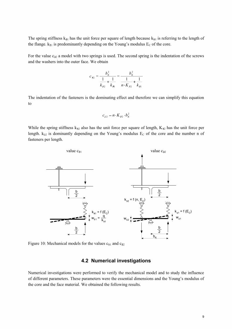
The spring stiffness k 1 has the unit force per square of length because k 1 is referring to the length of the flange. k 1 is predominantly depending on the Young’s modulus EC of the core.
For the value c 2 a model with two springs is used. The second spring is the indentation of the screws and the washers into the outer face. We obtain
12
2
12
2
2 1111kKn
b
kk
bc KK
The indentation of the fasteners is the dominating effect and therefore we can simplify this equation to
222 KbKnc
While the spring stiffness k 2 also has the unit force per square of length, K 2 has the unit force per length. k 2 is dominantly depending on the Young’s modulus EC of the core and the number n of fasteners per length.
value c 1 value c 2
b2
k 1 = f (EC)
b2
w 1 =q
k 1
b2
k 1 = f (EC)
b2
w 1w 2
bK
k 2 = f (n, EC)
Figure 10: Mechanical models for the values c 1 and c 2
4.2 Numerical investigations
Numerical investigations were performed to verify the mechanical model and to study the influence of different parameters. These parameters were the essential dimensions and the Young’s modulus of the core and the face material. We obtained the following results.
9
- For panels with two flat or lightly profiled faces (wall panels) both c 1 and c 2 depend on the thickness D of the panels. c 1 and c 2 increase with the thickness D. They converge to the value of the panel with a strongly profiled outer face (usually roof panels) with similar arrangement of the fasteners.
- Both values c 1 and c 2 increase with the depth of profiling of the outer face due to the support by this profiling. Beyond 10 mm of depth of this profiling no further increase of this is possible such that c 1 and c 2 there attain their limit values for a panel with a profiled outer face. This applies for the investigated geometry with a distance of ribs of 333 mm.
- Both c 1 and c 2 increase with Young’s modulus EC of the core material with the power of 0.9. The approximation by a linear function is justified.
- c 1 increases with the bending stiffness (EI)F2 of the inner face with the power of 0.1. The influence of this stiffness can therefore be neglected for the common parameter range (faces made of steel with thickness 0.38 mm tK 0.,71 mm, faces made of aluminium with 0.50 mm t 0.65 mm). For faces made of GFRP a reduction factor cF is required. As expected there is no influence of (EI)F1 of the outer face on c 1 such that (EI)F1 can also be disregarded. c 2 increases with the bending stiffness (EI)F1 of the outer face with the power less than 0.1 so the same applies as for c 1. There is no significant increase of c 2 with increasing bending stiffness (EI)F2 of the inner face. This justifies the mechanical model introduced above that c 2 only depends on the core material and the type of profiling of the outer face.
- c 1 does not increase with the square of b but with the power of 1.3 (thin wall panels) to 1.7 (thick wall panels): The actual lever arm is smaller than b because of the indentation and because of bending of the panel. c 2 increases with the square of b.
4.3 Evaluation of tests results
Based on the aforementioned considerations we used an approach of the form
211 bEcc C
to determine the value c 1 and an approach of the form
222 KC bEncc
to determine c 2. The number n of fasteners per meter length and the distance bK depend on the fixing pattern and the direction of rotation. c 2 should be set to zero unless bK 0.5 b. For double-symmetric beams with one sided fixing at one fourth of the flange bK = 0.75 b or bK = 0 applies, depending on the direction of rotation. For one-sided application of fixings this means that for one direction of rotation c 2 is always zero. In principle the same is true for alternating fixing patterns: bK is always
10

the longer lever arm and for n only the number of fasteners per length corresponding to this lever arm can be taken into account. Attention has to be paid to the units: c1 is non-dimensional value whereas c2 has the dimension meter because n as defined above has the dimension m-1. EC and bK are input with their units.
Creep tests were performed and evaluated to consider the effect of duration of loading on Young’s modulus EC of the core material. The extrapolation of the results of these tests according to EN 14509 to 2000 hours (representing snow loading) and 100000 hours (representing self-weight loading) resulted in values C,t much higher than the value C,100000 = 1.0 given in Dürr (2008). This increase to almost twice the value is mainly due to the statistical evaluation and the scatter of the test results. Finally the values C,t are provided for use with the formula
tC
CtC
EE
,, 1
The effect of temperature on Young’s modulus EC of the core material can be taken into account by using the reduction factor k1 according to EN 14509:
CCt
CCtCCC E
EEkEE
20,
80,,
31,,
From the tests with sandwich panels with faces made of GFRP additional reduction factors cF = 0.38 for c 1 and cF = 0.41 for c 2 were obtained. We recommend to use cF = 0.38 both for c 1 and c 2.
The final result is summarized in Table 4. The values listed for panels with a profiled outer face can be used for panels fixed in the lower flange of the outer face or in the upper flange and also for fixing with or without saddle washers as well because the differences of values found both in numerical and experimental investigations were to small to be seriously quantified.
Table 4: Values c 1 and c 2
Double-symmetric beams Z- or C-section
c 1 2
,,1 bEcc tCF 2,,1 bEcc tCF
c 2 2
,,2 KtCF bEncc 0
EC,t, CCt
CCt
tC
C
tC
CtC E
EEk
EE
20,
80,
,
31
,,, 11
mK 2bqd bqd
Table 5: Parameters
11
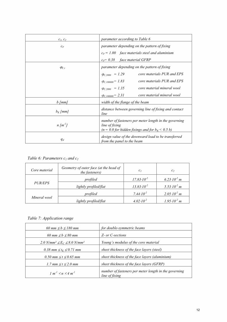
c1, c2 parameter according to Table 6
cF parameter depending on the pattern of fixing
cF = 1.00 face materials steel and aluminium
cF= 0.38 face material GFRP
C,t parameter depending on the pattern of fixing
C,2000 = 1.29 core materials PUR and EPS
C,100000 = 1.83 core materials PUR and EPS
C,2000 = 1.35 core material mineral wool
C,100000 = 2.31 core material mineral wool
b [mm] width of the flange of the beam
bK [mm] distance between governing line of fixing and contact line
n [m-1] number of fasteners per meter length in the governing line of fixing (n = 0.0 for hidden fixings and for bK < 0.5 b)
qd design value of the downward load to be transferred from the panel to the beam
Table 6: Parameters c1 and c2
Core material Geometry of outer face (at the head of the fasteners) c1 c2
PUR/EPS profiled 17.83 10-2 6.23 10-2 m
lightly profiled/flat 13.83 10-2 5.53 10-2 m
Mineral wool profiled 7.44 10-2 2.05 10-2 m
lightly profiled/flat 4.02 10-2 1.95 10-2 m
Table 7: Application range
60 mm b 180 mm for double-symmetric beams
60 mm b 80 mm Z- or C-sections
2.0 N/mm² EC 8.0 N/mm² Young’s modulus of the core material
0.38 mm tK 0.71 mm sheet thickness of the face layers (steel)
0.50 mm t 0.65 mm sheet thickness of the face layers (aluminium)
1.7 mm t 2.0 mm sheet thickness of the face layers (GFRP)
1 m-1 n 4 m-1 number of fasteners per meter length in the governing line of fixing
12
5. Conclusion
Sandwich panels increase the resistance of substructures (beams, purlins) against lateral torsional buckling by restraining the lateral displacements and rotations. The torsional restraint by sandwich panels can be calculated by using the mechanical model of a torsion spring with the spring stiffness c . This spring stiffness is a combination of the bending stiffness of the attached panel c C, the stiffness of the connection c A and the distortional stiffness c B of the beam to be stabilised.
The new rules given in the German design code DIN 18800-2 for the calculation of the stiffness of the connection c A which are based on investigations by Dürr (2008) are presented and their range of application is extended. The investigations for this extension were performed within the framework of the EASIE project.
Acknowledgements
This research has received financial support from the Industrieverband für Bausysteme im Metallleichtbau (IFBS), the German association of the producers of sandwich panels and thin-walled profiles. This paper also presents results obtained from the research of the EASIE project. The EASIE project has received financial support from the European Community’s Seventh Framework Programme FP7/NMP2-SE-2008 under grant agreement No 213302. We express our sincere gratitude for this support.
References
Dürr M (2008) “Die Stabilisierung biegedrillknickgefährdeter Träger durch Sandwichelemente und Trapezbleche” Berichte der Versuchsanstalt für Stahl, Holz und Steine der Universität Fridericiana in Karlsruhe, 5. Folge – Heft 17. Karlsruhe 2008.
Dürr M and Saal H (2009) “Die drehbettende Wirkung von Sandwichelementen beim Biegedrillknicknachweis in der Neufassung der DIN 18800-2” Bauingenieur 84: 247-253.
DIN 18800-2:2008-11: Stahlbauten – Teil 2: Stabilitätsfälle – Knicken von Stäben und Stabwerken
EN 14509:2006: Self-supporting double skin metal faced insulating panels – Factory made products – Specifications
13