STAAD Foundation
304
STAAD.foundation USER’S MANUAL DRAFT COPY a division of netGuru, Inc. www.reiworld.com www.reel.co.uk
-
Upload
joaquin-medina-sanchez -
Category
Documents
-
view
559 -
download
35
Transcript of STAAD Foundation

STAAD.foundation
USER’S MANUAL
DRAFT COPY
a division of netGuru, Inc. www.reiworld.com www.reel.co.uk

STAAD.foundation is a proprietary computer program of Research Engineers, International (REI), a division of netGuru, Inc. The program and this document have been prepared in accord with established industry engineering principles and guidelines. While believed to be accurate, the information contained herein should never be utilized for any specific engineering application without professional observance and authentication for accuracy, suitability and applicability by a competent and licensed engineer, architect or other professional. REI disclaims any liability arising from the unauthorized and/or improper use of any information contained in this document, or as a result of the usage of the program.
RELEASE 2003
Copyright Research Engineers, Interntional
Division of netGuru, Inc. Published January, 2004

About STAAD.foundation STAAD.foundation is a program from Research Engineers International, for the analysis and design of various types of foundations, such as individual footings, mats, pile caps and piles, etc.


Table of Contents
STAAD.foundation User’s Manual
Section 1 System Requirements, Installation and Start-up 1 - 1.1 Introduction 1 - 2 1.2 Hardware Requirements 1 - 4 1.3 Installation 1 - 5 1.4 Copy Protection Device 1 - 11 1.5 Running STAAD.foundation 1 - 12
Section 2 Theoretical Basis 2 - 2.1 Introduction to finite element analysis 2 - 2 2.2 Element load specification 2 - 6 2.3 Theoretical basis 2 - 7 2.4 Element local coordinate system 2 - 11 2.5 Output of element forces 2 - 12 2.6 Sign convention of element forces 2 - 14 2.7 STAAD.foundation program theory 2 - 18
Section 3 Quick Tour 3 - 3.1 Introduction 3 - 2 3.2 Starting a new project 3 - 3 3.3 Entering support coordinates 3 - 8 3.4 Defining the loads 3 - 10 3.5 Using jobs to specify design constraints 3 - 16 3.6 Entering design parameters 3 - 19 3.7 Performing an isolated footing design 3 - 21 3.8 Importing structural geometry and analysis results from STAAD.Pro 3 - 25 3.9 Creating a new job for a mat foundation 3 - 28 3.10 Setting up the grid and defining the mat boundary 3 - 30 3.11 Creating a mesh 3 - 36 3.12 Specifying slab thickness 3 - 40 3.13 Defining soil properties 3 - 44 3.14 Analyzing the slab 3 - 46 3.15 Slab design 3 - 54 3.16 Pile cap example 3 - 65 3.17 Entering pile data 3 - 66 3.18 Entering pile cap design parameters 3 - 71 3.19 Performing pile cap design and viewing results 3 - 73

3.20 Exporting drawings to CAD 3 - 79 3.21 Local footing editing features 3 - 80 3.22 Conclusion 3 - 82
Section 4 STAAD.foundation Graphical Environment 4 - 4.1 Introduction 4 - 2 4.2 STAAD.foundation screen organization 4 - 3 4.3 The page control 4 - 6
4.3.1 The Project Info Page 4 - 9 4.3.1.1 General Info 4 - 10 4.3.1.2 Review History 4 - 11
4.3.2 The Foundation Plan Page 4 - 12 4.3.2.1 Grid Setup 4 - 13 4.3.2.2 Column Positions 4 - 15 4.3.2.3 Column Dimensions 4 - 16 4.3.2.4 Pile for Mat Foundation 4 - 17 4.3.2.5 Physical Beams 4 - 18
4.3.3 The Loads and Factors Page 4 - 19 4.3.3.1 Load Description 4 - 20 4.3.3.2 New Load Case 4 - 21 4.3.3.3 Load Combination 4 - 30 4.3.3.4 Remove Load Case 4 - 33 4.3.3.5 Safety Factors 4 - 34
4.3.4 The Design Parameters Page 4 - 35 4.3.4.1 Concrete and Rebar 4 - 36 4.3.4.2 Cover and Soil 4 - 38 4.3.4.3 Geometry 4 - 40
4.3.5 The Pile Data Page 4 - 42 4.3.5.1 Pile Arrangement 4 - 43 4.3.5.2 Design Parameters 4 - 48
4.3.6 The Design Page 4 - 49 4.3.6.1 Design 4 - 50 4.3.6.2 Design Summary 4 - 52 4.3.6.3 Footing Layout 4 - 53 4.3.6.4 Detailed Drawing 4 - 54 4.3.6.5 Calculation Sheet 4 - 57
4.3.7 The Meshing Page 4 - 58 4.3.7.1 Meshing Grid 4 - 59 4.3.7.2 Meshing Setup 4 - 65 4.3.7.3 Create Mesh 4 - 67
4.3.8 The Property-Soil-Material Page 4 - 68 4.3.8.1 Beam Properties 4 - 69 4.3.8.2 Plate Thickness 4 - 72 4.3.8.3 Beam Offset 4 - 75 4.3.8.4 Soil Properties 4 - 78

4.3.9 The Analysis Page 4 - 81 4.3.9.1 Analyze 4 - 82 4.3.9.2 Displacements 4 - 84 4.3.9.3 Support Reactions 4 - 88 4.3.9.4 Plate Stresses 4 - 92
4.3.10 The Slab Design Page 4 - 93 4.3.10.1 FEM Slab Design 4 - 94 4.3.10.2 Slab Detailing 4 - 102 4.3.10.3 Section Design Along a Line 4 - 103
4.4 The Menu Commands 4 - 108 4.4.1 File Menu 4 - 109 4.4.2 Edit Menu 4 - 112 4.4.3 View Menu 4 - 113 4.4.4 Tools Menu 4 - 123 4.4.5 Select Menu 4 - 134 4.4.6 Grid Setup Menu 4 - 140 4.4.7 Window Menu 4 - 145 4.4.8 Help Menu 4 - 149
4.5 The Toolbars 4 - 154 4.5.1 File Toolbar 4 - 155 4.5.2 Print Toolbar 4 - 157 4.5.3 Jobs Toolbar 4 - 160 4.5.4 Help Toolbar 4 - 4.5.5 Edit Toolbar 4 - 4.5.6 Rotate Toolbar 4 - 4.5.7 Zoom Toolbar 4 - 4.5.8 Loading Toolbar 4 - 4.5.9 Tools Toolbar 4 - 4.5.10 Geometry Toolbar 4 -


1-1
System Requirements, Installation and Start-up
This section describes the following topics:
• Introduction • Hardware Requirements • Installation • Copy Protection Device • Running STAAD.foundation
Section 1

STAAD.foundation – User’s Manual
Section 1 – System Requirements, Installation and Start-up
1-2
1.1 Introduction
Thank you for your purchase of STAAD.foundation. STAAD.foundation is an exhaustive analysis, design, and drafting solution for a variety of foundations that include isolated and combined footings, mat foundations, pile caps and slab on grade. A part of the STAAD.Pro family of products, STAAD.foundation is a cost-saving downstream application that enables engineers to analyze and design the underlying foundation for the structure they created in STAAD.Pro. STAAD.foundation can automatically absorb the geometry, loads and results from a STAAD.Pro model and accurately design isolated or combined footings, true mat foundations and even perform pile cap arrangements. STAAD.foundation not only analyzes and designs a myriad of foundation configurations, but will also produce production quality reports and detailed 3D rendering of your foundation structures. With full OpenGL graphics, engineers can clearly see the displaced shape, stress distribution, reinforcement layout and force diagrams of their supporting structure. All models use physical objects including physical beams and slabs that do not require the user to mesh the surface. For mat foundation designs, STAAD.foundation utilizes a true finite element design using the individual element stresses rather than using column strips. STAAD.foundation can be used in a stand-alone mode or can be used in conjunction with STAAD.Pro where the support reactions from the main model and associated load cases are automatically brought in. Because STAAD.foundation provides a total solution for your foundation needs, a built-in project management system enables line and span of control, revision records and multi-job functionalities. This helps you reduce cost in assembling the technical and managerial information for your foundation. Full step-by-step calculations are also provided in HTML form (where possible) to verify each and every output provided by the program.

Section 1 – System Requirements, Installation and Start-up
1-3
These verification checks can be easily shared with your clients for approval. STAAD.foundation also includes a robust drafting module, which enables you to customize your contract or site drawings including the reinforcement and plan layouts. With an assortment of CAD tools and an interface with AutoCAD, general arrangement drawings can be created quickly. We hope you enjoy your experience with STAAD.foundation. If you have any questions or problems with the program, please visit our technical support page at http://www.reiworld.com or email at us at [email protected].

STAAD.foundation – User’s Manual
Section 1 – System Requirements, Installation and Start-up
1-4
1.2 Hardware Requirements
The following requirements are suggested minimums. Systems with increased capacity provide enhanced performance. • PC with Intel-Pentium / AMD processor. • Graphics card and monitor with 1024x768 resolution, 256 color
display (16 bit high color recommended). • 128 MB RAM or higher. • Windows 98/ NT 4.0 or higher operating system. Running it on
Windows 95 systems is not recommended as performance may be degraded.
• Sufficient free space on the hard disk to hold the program and data files. The disk space requirement will vary depending on the modules you are installing. A typical minimum is 500MB free space.
• A multi-media ready system with sound card and speakers is needed to run the tutorial movies and slide shows.
Note: Additional RAM, disk space, and video memory will enhance the performance of STAAD.foundation. The user must have a basic familiarity with Microsoft Windows 95/NT systems in order to use the software.

Section 1 – System Requirements, Installation and Start-up
1-5
1.3 Installation
Close all applications before installing STAAD.foundation. Typically, an InstallShield Wizard screen appears when the CD is placed in the drive as shown in Figure 1.1. If it does not, you may initiate it by running SETUP.EXE located at the root folder of the CD (This can be done by clicking on the file named SETUP.EXE from Windows Explorer). Note: In Windows NT, Windows 2000, and Windows XP systems, you have to log in with administrative rights before commencing installation.
Figure 1. 1 - InstallShield Wizard

STAAD.foundation – User’s Manual
Section 1 – System Requirements, Installation and Start-up
1-6
Users who are installing the commercial version of the program will encounter the following screen in Figure 1.2.
Figure 1. 2 - Customer Information & Serial Number
The serial number required for this screen should be available on the back of the CD casing. Users of the Demo Version will not be required to provide the above information. The next screen you will encounter is shown in Figure 1.3. It pertains to the type of software security system that you purchased with STAAD.foundation. A Local Security generally refers to a hardware lock, which is an adapter-like device that is placed on the parallel or USB port of your computer. It can also be a software-based system (instead of a hardlock), which is a software license that binds STAAD.foundation to the specific computer you are installing it on. Network Security refers to a system that supports simultaneous multiple-user access. A separate instruction document containing the steps for network installations is provided to users who have opted for this type of security system.

Section 1 – System Requirements, Installation and Start-up
1-7
Figure 1. 3 - Selection of Security System Type
If you choose Local Security, you are asked to select the type of hardware lock supplied to you, or the software license that is applicable. The name of the lock is engraved on the cover of the lock. Make sure the type of lock you choose from Figure 1.4 matches that name. This is absolutely necessary to ensure that the program functions to its full capacity.

STAAD.foundation – User’s Manual
Section 1 – System Requirements, Installation and Start-up
1-8
Figure 1. 4 - Selection of Hardware Lock Type
You may install the program in any folder of your choice. A default folder name is supplied to you as shown in Figure 1.5.

Section 1 – System Requirements, Installation and Start-up
1-9
Figure 1. 5 - Selection of the Installation Folder
The next screen allows you to review the settings you have chosen before copying the files for STAAD.foundation to your computer as shown in Figure 1.6.

STAAD.foundation – User’s Manual
Section 1 – System Requirements, Installation and Start-up
1-10
Figure 1. 6 - Review Settings
After the installation is complete, please restart your machine for the changes to take effect.

Section 1 – System Requirements, Installation and Start-up
1-11
1.4 Copy Protection Device
As explained in the previous section, a copy protection device in the form of a hardware lock, or a software license, is required to run STAAD.foundation. The hardware lock must be inserted in the parallel port of your computer and must remain there during the entire duration that you are in STAAD.foundation. If any other device, such as a printer cable, hardware lock for other software, etc., is attached to the parallel port, we recommend that you attach the STAAD.foundation hardware lock in front of such devices. In case you have multiple locks, and cannot stack them for any reason, REI can replace your parallel port type with a USB type lock. The hardware lock is configured for the programs and modules that you have purchased. If you install one of the programs or modules that is not supported by the hardware lock, that component may not be accessible, or will be operable only as a Demonstration version. The hardware lock driver(s) are automatically installed during the installation process. For computers running on Windows NT, Windows 2000, or Windows XP, you must have administrative rights before installing the program to enable proper installation of the hardware lock driver files. STAAD.foundation requires the hardlock be in place during the entire time that any and all tasks are being performed. In other words, from the moment you start the program till the moment you exit it, the lock has to be in place. If the lock is detached at any time in between, the program will stop running, and request that you re-attach the lock. In the event that you are unable to, it will provide the opportunity to save the work and exit the program. To resume your work, you will have to put the lock back in the port and re-start the program.

STAAD.foundation – User’s Manual
Section 1 – System Requirements, Installation and Start-up
1-12
1.5 Running STAAD.foundation
Click on the STAAD.foundation icon from the STAAD.foundation program group as shown in figure 1.7.
Figure 1. 7 - Starting STAAD.foundation
The STAAD.foundation main screen appears as shown in figure 1.8.

Section 1 – System Requirements, Installation and Start-up
1-13
Figure 1. 8 - The STAAD.foundation Screen
If you are a first time user who is unfamiliar with STAAD.foundation, we suggest that you go through the Quick Tour in Section 2 and the tutorials in Section 4.

1-14

2-1
Theoretical Basis
This section describes the following topics:
• Introduction to Finite Element Analysis • Element Load Specification • Theoretical Basis • Element Local Coordinate System • Output of Element Forces • Sign Convention of Element Forces • STAAD.foundation Program Theory
Section 2

STAAD.foundation - User’s Manual
Section 2 – Theoretical Basis
2-2
2.1 Introduction to Finite Element Analysis
If you want to model a surface entity like a wall, a roof or a slab, where the load is distributed in more than one direction, you need a surface entity to carry that kind of loading. The kind of entity that is used to model a beam or a column cannot be used to model a slab. We need to use another kind of structural entity known as a finite element. In a finite element analysis, you take a wall or a slab and subdivide it into smaller parts consisting of triangles or quadrilaterals. Finite elements are often referred to as plates. In our discussion, we may use these two words interchangeably. The difference between a beam and a plate is that a load that is applied to a beam can really go in only two directions, towards one end, or the other, or both.
Figure 2. 1 In a plate, there is more than one path for the load to flow.
Figure 2. 2

Section 2 – Theoretical Basis
2-3
A plate can be 3-noded (triangular) or 4-noded (quadrilateral). The thickness of an element may be different from one node to another. All nodes of a 4-noded plate must lie in the same plane. If the four nodes of a quadrilateral element do not lie on one plane, you should replace the quadrilateral element with two triangular elements. It is not possible to accurately model the behavior of a slab using just a single element. Why not? One reason is that you can determine the displacements in the finite element only at the corner nodes. With a beam, if you know the displacements at the ends, you can use secondary analysis techniques like the moment-area method to determine the displacements at intermediate points.
Figure 2. 3
In a plate, there are no equations you can use to determine the displacement at some arbitrary point within the 3 or 4 corners of the element. So, if you would like to know the displacements at some interior points of the slab, or if you would like to know the deformed shape along the edges of the slab, it is necessary to model the slab using a series of plate elements in such a manner that the points of interest become nodes of the elements.
Similarly, you can accurately determine the stresses only at the center of the element. The only way to find the stresses at other points is to interpolate values at points between the centers of adjacent elements.

STAAD.foundation - User’s Manual
Section 2 – Theoretical Basis
2-4
Suppose you had a slab supported by a frame, and supposing that under load it had a deflected shape something like that shown in the figure below.
Figure 2. 4
In order to obtain deflection information that would allow you to plot the deflected shape, you would need to at least know the deflections at the points of maximum deflection, at the end points, and at a few intermediate points, as shown by the X’s in the figure. The more points you have, the more accurately you can model the deflected shape. On the other hand, you would not want hundreds of points either, since it would make your structure too cumbersome to analyze. You need to exercise judgment in selecting the number of elements you use to model a slab, enough to accurately model the behavior of the slab under load, but not so many as to make the model difficult to work with.
Another situation in which you would need more than one plate element to model a slab would be when you want to know the stresses in a slab caused by some type of point loading. You would want to have quite a few elements in the vicinity of where the point loading occurs in order to determine the stress distribution in the slab caused by the concentrated load.
So, rather than just a single element or a few elements, a series or matrix of finite elements is often needed to model the behavior of a wall or slab. This series of elements is commonly referred to as a mesh. Once you have created a mesh, incorporated it into a model, and used it as a basis for further developing the model, it can be difficult to go back later and change the size (i.e. the ‘density’) of

Section 2 – Theoretical Basis
2-5
the mesh. Here are some suggestions that may help you determine the mesh size that you need.
• Try to predict the approximate deflected shape of the plate or slab. For example, a simply supported plate deflects like a bowl. If you cut a section that intersects the middle of its edges, the longitudinal section as well as the transverse section both look like a "U". How many points does one need to represent the U? Probably four points for each half of the "U" would be a minimum number needed to be able to visualize the deflected shape. Four points would mean that three elements on each half of the "U', thus six elements each in the local X and Y directions would be required. If the edges of the element are fixed or monolithic with a concrete beam, the deflected shape is more like an inverted hat. In this case, one would perhaps need nine or more points to represent the deflected shape. That means eight or more elements in that direction.
• Do you have concentrated forces on the surface of the
element? If so, you need to have a finer mesh around that region in order to visualize the deflected shape or the stresses at that location. How many elements are needed is hard to say. But, for example, one can estimate a circular area around the concentrated load point, divide that circle into say 30 degree pie-shaped segments, thus obtaining 12 triangular elements around a circle whose center is the location of the point load.
• Do you have holes in the plate? You need a finer mesh
around the holes. Again, there are no easy guidelines for how many elements there ought to be. Engineering judgment is often the best guideline.

STAAD.foundation - User’s Manual
Section 2 – Theoretical Basis
2-6
2.2 Element Load Specification
The following load specifications are available: 1) Joint loads at element nodes in global directions. 2) Concentrated loads at any user specified point within the
element in global or local directions. 3) Uniform pressure on element surface in global or local
directions 4) Partial uniform pressure on user specified portion of element
surface in global or local directions 5) Linearly varying pressure on element surface in local
directions.

Section 2 – Theoretical Basis
2-7
2.3 Theoretical Basis
The STAAD plate finite element is based on hybrid finite element formulations. A complete quadratic stress distribution is assumed. For plane stress action, the assumed stress distribution is as follows.
τxy
τyx
τxy
τyx
σy
σx
σy
σx
Figure 2. 5 Complete quadratic assumed stress distribution:
a1 through a10 = constants of stress polynomials.

STAAD.foundation - User’s Manual
Section 2 – Theoretical Basis
2-8
The following quadratic stress distribution is assumed for plate bending action:
M X
Y
Z
M
M
M
M
M
M
Q
Q
Q
Q
x
y
xy
yx
x
y
yx
x x
y
y
M xy
Figure 2. 6 Complete quadratic assumed stress distribution:
a1 through a13 = constants of stress polynomials. The distinguishing features of this finite element are: 1) Displacement compatibility between the plane stress component of
one element and the plate bending component of an adjacent element which is at an angle to the first (see Fig. below) is achieved by the elements. This compatibility requirement is usually ignored in most flat shell/plate elements.

Section 2 – Theoretical Basis
2-9
Figure 2. 7
2) The out of plane rotational stiffness from the plane stress
portion of each element is usefully incorporated and not treated as a dummy as is usually done in most commonly available commercial software.
3) Despite the incorporation of the rotational stiffness mentioned previously, the elements satisfy the patch test absolutely.
4) These elements are available as triangles and quadrilaterals, with corner nodes only, with each node having six degrees of freedom.
5) These elements are the simplest forms of flat shell/plate elements possible with corner nodes only and six degrees of freedom per node. Yet solutions to sample problems converge rapidly to accurate answers even with a large mesh size.
6) These elements may be connected to plane/space frame members with full displacement compatibility. No additional restraints/releases are required.
7) Out of plane shear strain energy is incorporated in the formulation of the plate bending component. As a result, the elements respond to Poisson boundary conditions which are considered to be more accurate than the customary Kirchoff boundary conditions
8) The plate bending portion can handle thick and thin plates, thus extending the usefulness of the plate elements into a multiplicity of problems. In addition, the thickness of the plate is taken into consideration in calculating the out of plane shear.

STAAD.foundation - User’s Manual
Section 2 – Theoretical Basis
2-10
9) The plane stress triangle behaves almost on par with the well known linear stress triangle. The triangles of most similar flat shell elements incorporate the constant stress triangle which has very slow rates of convergence. Thus the triangular shell element is very useful in problems with double curvature where the quadrilateral element may not be suitable.
10) Stress retrieval at nodes and at any point within the element.

Section 2 – Theoretical Basis
2-11
2.4 Element Local Coordinate System
The precise orientation of local coordinates is determined as follows: 1) The vector pointing from I to J is defined to be parallel to the
local x- axis. 2) The cross-product of vectors IJ and IK defines a vector parallel
to the local z-axis, i.e., z = IJ x IK. 3) The cross-product of vectors z and x defines a vector parallel to
the local y- axis, i.e., y = z x x. 4) The origin of the axes is at the center (average) of the 4 joint
locations (3 joint locations for a triangle). The sign convention of output force and moment resultants is illustrated in Fig. 1.13.
Figure 2. 8

STAAD.foundation - User’s Manual
Section 2 – Theoretical Basis
2-12
2.5 Output of Element Forces
ELEMENT FORCE outputs are available at the following locations:
A. Center point of the element. B. All corner nodes of the element. C. At any user specified point within the element.
Following are the items included in the ELEMENT STRESS output. SQX, SQY Shear stresses (Force/ unit len./ thk.) SX, SY, SXY Membrane stresses (Force/unit len./ thk) MX, MY, MXY Bending moments per unit width (Moment/unit
len.) SMAX, SMIN Principal stresses (Force/unit area) TMAX Maximum shear stress (Force/unit area) ANGLE Orientation of the principal plane (Degrees) VONT, VONB Von Mises stress, where
( ) 222 SMINSMAXSMINSMAX707.0 VM ++−=
TRESCAT, TRESCAB Tresca stress, where TRESCA = MAX[ |(Smax-Smin)| , |(Smax)| , |(Smin)| ] Notes:
1. All element stress output is in the local coordinate system. The direction and sense of the element stresses are explained in Fig. 1.13.
2. To obtain element stresses at a specified point within the element, the user must provide the coordinate system for the element. Note that the origin of the local coordinate system coincides with the center node of the element.

Section 2 – Theoretical Basis
2-13
3. Principal stresses (SMAX & SMIN), the maximum shear stress (TMAX), the orientation of the principal plane (ANGLE), the Von Mises stress (VONT & VONB), and the Tresca stress (TRESCAT & TRESCAB) are also printed for the top and bottom surfaces of the elements. The top and the bottom surfaces are determined on the basis of the direction of the local z-axis.

STAAD.foundation - User’s Manual
Section 2 – Theoretical Basis
2-14
2.6 Sign Convention of Element Forces
Figure 2. 9
Figure 2. 10

Section 2 – Theoretical Basis
2-15
Figure 2. 11
Figure 2. 12

STAAD.foundation - User’s Manual
Section 2 – Theoretical Basis
2-16
Figure 2. 13
Figure 2. 14

Section 2 – Theoretical Basis
2-17
Figure 2. 15
Figure 2. 16

STAAD.foundation - User’s Manual
Section 2 – Theoretical Basis
2-18
2.7 STAAD.foundation Program Theory
STAAD.foundation performs structural design of foundations in accordance with the ACI 318-02 Code. The available foundation types are: isolated spread footing, pile cap, and mat. 1. Isolated Spread Footing
The program uses the following criteria:
a. soil bearing capacity, b. shear and flexural strength of footing (no shear
reinforcing assumed), c. compressive and flexural strength of pedestal
Step 1 – Determine footing plan geometry based on loading and bearing resistance of the soil. Stress distribution under the footing is assumed to be linear. For eccentrically loaded footings, the stresses may become tensile under part of the foundation. In such cases the program sets stress values in uplift zones to zero and calculates new values elsewhere for the revised equilibrium condition. The final plan dimensions of the footing are established iteratively from the condition that the maximum stress should not exceed the factored bearing resistance of the soil. Step 2 - Calculate footing thickness based on structural capacity in shear and bending. Structural design of the footing consist of the following: a. Punching shear check, in accordance with Section
11.12.2, at a distance of d/2 from the pedestal. The critical section comprises four straight line segments, parallel to the corresponding sides of the pedestal.

Section 2 – Theoretical Basis
2-19
b. One way shear (beam action), in accordance with Sections 11.1 through 11.5, at a distance of d from the face of the pedestal, in both orthogonal directions. The critical plane is assumed to extend over the entire width/length of the footing.
c. Bending, in accordance with Sections 15.4.2 and 10.3.4,
with the critical planes located at both orthogonal faces of the pedestal and extending across the full width/length of the footing.
2. Pile Cap
The program produces the following design output: a. Required pile quantity and layout to satisfy loading
applied to the footing, based on bearing, uplift and lateral pile capacity,
b. Geometry of the pile cap, based on shear and bending strength requirements at critical sections of the footing.
Step 1 - Pile Arrangement
The user provides the following pile properties: capacity (bearing, uplift, and lateral), diameter, spacing, and edge distance. Based on these parameters, the program determines the required pile configuration as well as plan dimensions of the footing from the condition, that the force transferred to any pile should not exceed its capacity. For a general case of vertical and horizontal forces, and bending moments acting on the cap, that stipulation is equivalent to satisfying the following two equations:
Hpile >= Happl / N Vpile >= Vappl / N + Mxappl * Ry / Ixg + Myappl * Rx / Iyg

STAAD.foundation - User’s Manual
Section 2 – Theoretical Basis
2-20
where: Hpile - single pile horizontal capacity Vpile - single pile vertical capacity Happl - total horizontal load applied Vappl - total vertical load applied N - total number of piles in footing Mxappl - applied bending moment about X axis Myappl - applied bending moment about Y axis Rx - distance from Y axis to the farthest pile Ry - distance from X axis to the farthest pile Ixg - pile group moment of inertia about X
axis Iyg - pile group moment of inertia about Y
axis
Note: X and Y axes above are centroidal axes of the pile group, Ixg and Iyg are calculated treating each pile as a unit, and are equal Σ(1*yi
2) and Σ(1*xi2),
respectively.
The program includes a library of possible pile layouts for quantities from 1 to 25 piles. Based on the user input, the program recommends the most economical (least number of piles) layout. The user may select any other layout/quantity if desired, however. In addition, the selected pile layout may be modified by changing the coordinates of individual piles. Alternatively, the user may input the entire configuration by hand. The layout recommended by the program is guaranteed to satisfy the load/capacity ratio for all piles. Should the user-modified or manually input layouts result in pile overstressing, the program will flag this deficiency in the design output.

Section 2 – Theoretical Basis
2-21
Step 2 - Design of Pile Cap Proportioning of the pile cap involves satisfying the shear (one and two way) and bending requirements at applicable critical sections, in accordance with Chapter 15 of ACI 318-02.
a) One way shear is checked in two areas:
i. At outer piles, with the critical section located at a
min. distance d from the face of a corner pile or faces of a pile group along the edge of the footing,
ii. At the distance d from two orthogonal faces of the pedestal.
The critical shear plane is assumed along a shortest straight line connecting free edges of the footing. The design is then performed for the total pile reaction force on one side of the shear plane, in accordance with Sections 11.1 through 11.5.
b) Two way shear is checked in three areas:
i. At outer piles, with the critical section located at a
min. distance d/2 from the face of a corner pile or faces of a pile group along the edge of the footing. The critical plane is assumed along a straight and curved lines so positioned, that the total section length is minimized.
ii. At the distance d/2 around the pedestal. The section comprises four straight line segments, parallel to corresponding sides of the column.
iii. At the distance d/2 around a pile.
The design is performed for the total pile reaction force acting within the perimeter of the critical section, in accordance with Sections 11.12.2 through 11.12.6.

STAAD.foundation - User’s Manual
Section 2 – Theoretical Basis
2-22
c) Flexure is checked for critical planes located at both faces of the pedestal. The bending moment is calculated as an aggregate of moments due to pile reactions on one side of the plane.
Determination of an individual pile contribution to the forces at a critical section is based on whether the pile is outside this section (full reaction value assumed), inside the section (reaction ignored), or at an intermediate location (partial reaction assumed), as per Section 15.5.4.
3. Mat (Raft Foundation)
Analysis and design of mats is based on finite element method (FEM) coupled with slab-on-elastic-subgrade principles. First, a finite element model of the proposed mat foundation is created by the user. This may be accomplished in one of two ways:
a) importing a STAAD file of the superstructure, thus
providing reference points for initial mat set-up and load information, and defining boundaries of the mat, or
b) creating the foundation slab from scratch and inputting loading information manually.
Modeling of the foundation involves meshing of the slab to generate grid of finite elements. As with any FEM project, the denser the grid (smaller elements), the more precise results will be obtained. In addition to the slab, the raft may include a number of beams between the column locations. Since the beams would normally be part of the foundation, the slab polygonal meshing algorithm accounts for the presence of the beam and ensures that they become continuously integral with the slab. New nodes are purposely created on the centerline of the beam and the beam is split between those points into a number of segments.

Section 2 – Theoretical Basis
2-23
Once the mat is defined and all material/soil properties are input, the program may proceed with the analysis of the structure. It is performed by the state-of-the-art STAAD Analysis Engine. Realistic soil response is achieved by employing non-linear (compression only) spring supports to model subgrade reactions. Pile reactions, if present, are proportional to linear displacements of the supported node and include both compression and tension (uplift). The program calculates internal forces and deflections for all slab and beam elements of the foundation. This information is then used in the design stage of the program to:
a) establish the required top and bottom flexural
reinforcing in two orthogonal directions, b) check punching shear capacity at column locations.
The flexural design is done in accordance with Chapter 10 of the Code. The reinforcement areas are computed for a notional band one unit of length wide. The program allows the designer, as an option, to use the Wood-Armer equations for reinforcement calculations, as follows: a) Mx, My, and Mxy are fetched or calculated, as described
above. They are used to compute the values of design moments, Mxd and Myd.
b) For top reinforcement, the program computes:
Mx1 = Mx + abs(Mxy) My1 = My + abs(Mxy) Mx2 = Mx + abs(Mxy2 / My) My2 = My + abs(Mxy2 / Mx)

STAAD.foundation - User’s Manual
Section 2 – Theoretical Basis
2-24
If both Mx1 and My1 are positive, Mxd = Mx1 and Myd = My1. If both Mx1 and My1 are negative, Mxd = 0 and Myd = 0. If Mx1 is negative and My1 positive, Mxd = 0 and Myd = My2. If My1 is negative and Mx1 positive, Mxd = Mx2 and Myd = 0.
c) For bottom reinforcement:
Mx1 = Mx - abs(Mxy) My1 = My - abs(Mxy) Mx2 = Mx - abs(Mxy2 / My) My2 = My - abs(Mxy2 / Mx)
If both Mx1 and My1 are positive, Mxd = 0 and Myd = 0. If both Mx1 and My1 are negative, Mxd = Mx1 and Myd = My1. If Mx1 is negative and My1 positive, Mxd = Mx2 and Myd = 0. If My1 is negative and Mx1 positive, Mxd = 0 and Myd = My2.
Mxd and Myd are then used in lieu of Mx and My for calculations of the required reinforcing. Use of the modified bending moments brings about more accurate distribution of the reinforcing, better matching critical areas of the slab.
Flexural design notes: Reinforcement calculations for slab panels are based on Chapter 10 of ACI 318-02. The minimum reinforcing ratio complies with the limits prescribed for shrinkage and temperature reinforcement in Section 7.12. Maximum spacing of rebar is 18 in. The maximum reinforcing ratio corresponds to the net tensile strain at nominal strength equal to 0.004 (Clause 10.3.5). Strength reduction factor is established in accordance with Section 9.3.2.

Section 2 – Theoretical Basis
2-25
Punching shear design notes: Design for two-way shear is carried out in accordance with Section 11.12. The unbalanced moment transfer by eccentricity of shear is based on Clause 11.12.6. Shear strength of concrete is based on Clause 11.12.2.1. Strength reduction factor used is 0.75, in accordance with Section 9.3.2.
The program computes shear stress values at four corners of the rectangular critical section located at the distance of d/2 from edges of a column. The calculations include the unbalanced moment transfer effect, if applicable, in accordance with 11.12.6.2.

2-26

3-1
Quick Tour
This section describes the following topics:
• Introduction • Starting a New Project • Entering Support Coordinates • Defining the Loads • Using Jobs to Specify Design Constraints • Entering Design Parameters • Performing an Isolated Footing Design • Importing Structural Geometry and Analysis Results from
STAAD.Pro • Creating a New Job for a Mat Foundation • Setting up the Grid and Defining the Mat Boundary • Creating a Mesh • Specifying Slab Thickness • Defining Soil Properties • Analyzing the Slab • Slab Design • Pile Cap Example • Entering Pile Data • Entering Pile Cap Design Parameters • Performing Pile Cap Design and Viewing Results • Exporting Drawings to CAD • Local Footing Editing Features
Section 3
STAAD.foundation – User’s Manual
Section 3 – Quick Tour
3-2
3.1 Introduction
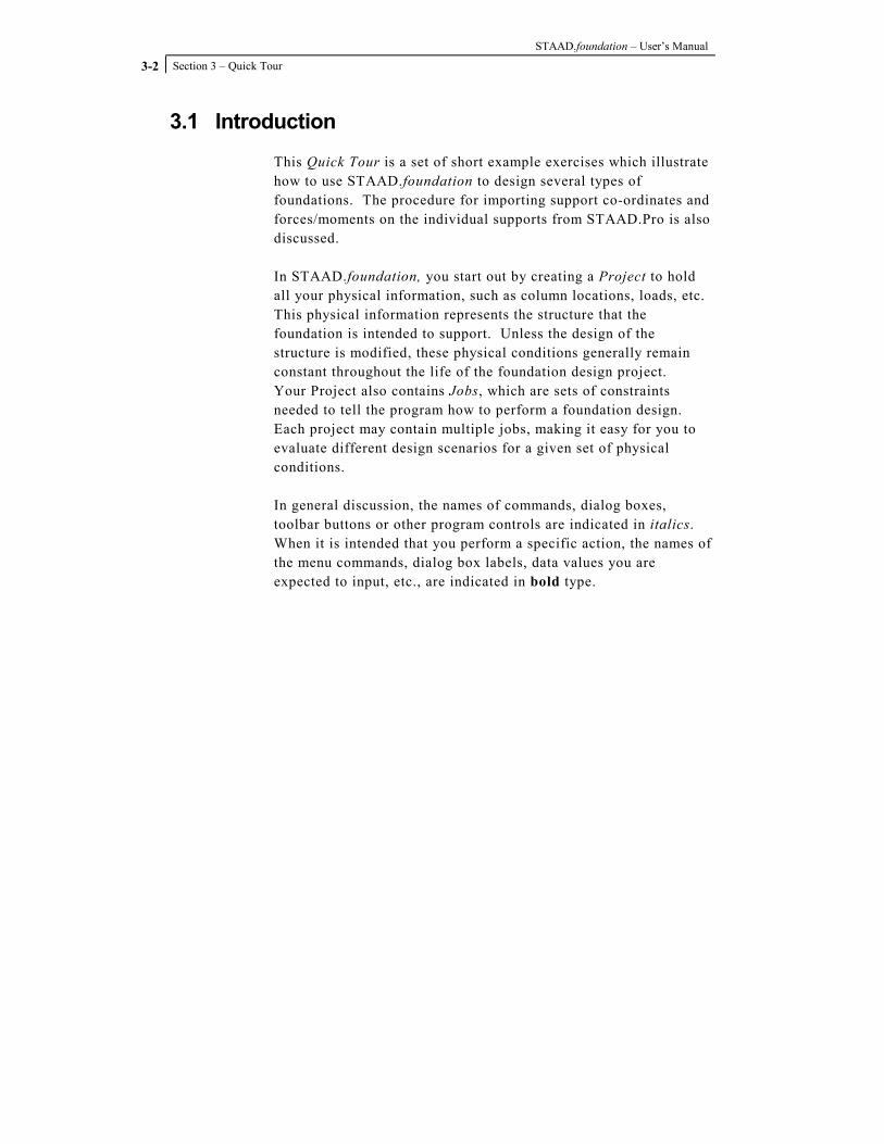
This Quick Tour is a set of short example exercises which illustrate how to use STAAD.foundation to design several types of foundations. The procedure for importing support co-ordinates and forces/moments on the individual supports from STAAD.Pro is also discussed. In STAAD.foundation, you start out by creating a Project to hold all your physical information, such as column locations, loads, etc. This physical information represents the structure that the foundation is intended to support. Unless the design of the structure is modified, these physical conditions generally remain constant throughout the life of the foundation design project. Your Project also contains Jobs, which are sets of constraints needed to tell the program how to perform a foundation design. Each project may contain multiple jobs, making it easy for you to evaluate different design scenarios for a given set of physical conditions. In general discussion, the names of commands, dialog boxes, toolbar buttons or other program controls are indicated in italics. When it is intended that you perform a specific action, the names of the menu commands, dialog box labels, data values you are expected to input, etc., are indicated in bold type.

Section 3 – Quick Tour
3-3
3.2 Starting a New Project To start the program, click on the Windows Start menu. Select the Programs option, select the STAAD.foundation program group, then click on the STAAD.foundation program icon.
Figure 3. 1
The software opens up with only the File, View and Help menus to start with..
Figure 3. 2
We may start our project from the File menu. We may start a New file, Open an existing file or Import an analyzed file from a structural analysis program like STAAD.Pro.
STAAD.foundation – User’s Manual
Section 3 – Quick Tour
3-4
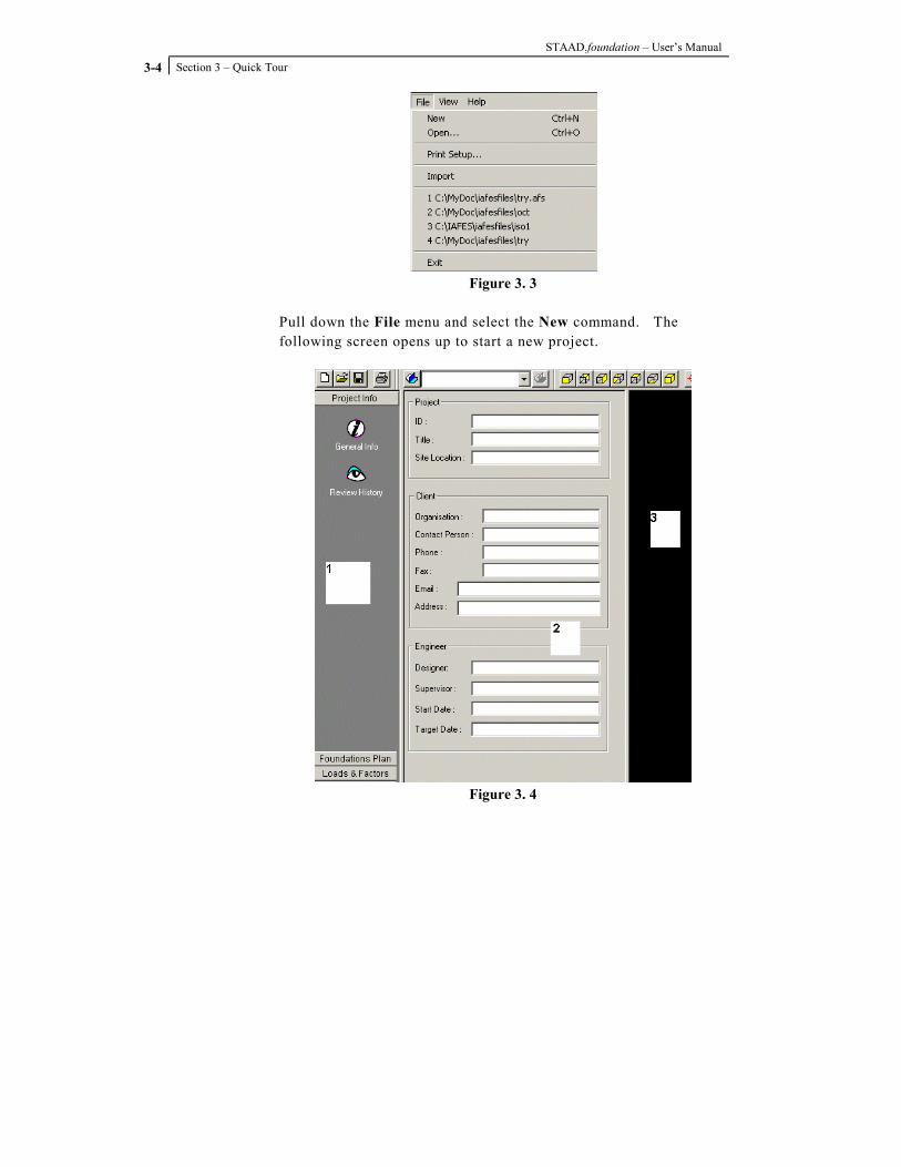
Figure 3. 3
Pull down the File menu and select the New command. The following screen opens up to start a new project.
Figure 3. 4

Section 3 – Quick Tour
3-5
This introduces the split multi-pane window environment of STAAD.foundation. Window 1, the left-most window, is called the Page Control. It contains the tabs and icons required to go to the different pages. It controls the display of forms used to provide input data. The Page Control is arranged from top to bottom in a logical design sequence. If you start at the top page and work your way down, you will be able to input all the data needed to perform a successful design. Window 2, located to the immediate right of the Page Control, is called the Data Area. It contains the forms to provide input data. Window 3, on the right side of the screen, is called the Main View. It contains the graphical display of the input. The first default page which we are currently viewing is invoked by clicking the ‘General Info’ icon of the “Project Info” tab (from now on we will be denoting the icons with ‘’ and the tabs with “”).
Figure 3. 5
We may fill up the edit boxes shown in the form to store the project-related data.

STAAD.foundation – User’s Manual
Section 3 – Quick Tour
3-6
Figure 3. 6
Later we will be able to display these data automatically in reports and drawings. If we click on the ‘Review History’ icon, a history table will be displayed in the Data Area.
Figure 3. 7

Section 3 – Quick Tour
3-7
A date, time, job name, originator and comments may be entered for each revision of the project. The comments for a given revision will be shown in the Comments box if we highlight the respective revision row. The Save button should be clicked after inserting any new revision history data to update the revision history table. If we want to delete a particular revision history record we highlight it by clicking on the respective Id and click the Delete button. If we want to delete the entire revision history we click on Delete All.

STAAD.foundation – User’s Manual
Section 3 – Quick Tour
3-8
3.3 Entering Support Coordinates
Now we would like to enter the coordinates of the different supports in the project to construct the foundation plan. Click on the tab called “Foundation Plan”.
Figure 3. 8
The following Column Positions default page will appear.
Figure 3. 9
Input the support coordinates (0,0,0), (10,0,0), (10,0,10), (0,0,15), (14,0,0) and (5,0,5) for Nodes 1, 2, 3, 4, 5 and 6 respectively. The Tab key or the arrow keys may be used to move from one cell to the next in the table. The supports along with their respective node numbers are displayed in the Main View. Please note that a support will not be shown in the display window until we click on any of the cells in the row below it. The coordinates can be deleted or modified like any spreadsheet input.

Section 3 – Quick Tour
3-9
3.4 Defining the Loads
After we specify the node coordinates we start defining the loads on different nodes. Click on the “Loads and Factors” tab in the Page Control to invoke the load definition page.
Figure 3. 10
Now click on the ‘New Load Case’ icon to invoke the following dialog box.
Figure 3. 11
Leave the Load Number set to its default value of 1. Enter the title Load Case 1 in the Load Title edit box.
STAAD.foundation – User’s Manual
Section 3 – Quick Tour
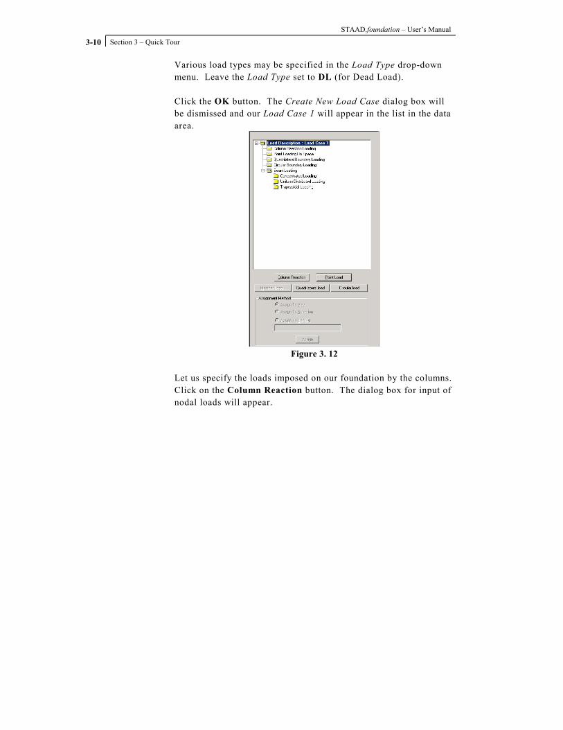
3-10
Various load types may be specified in the Load Type drop-down menu. Leave the Load Type set to DL (for Dead Load). Click the OK button. The Create New Load Case dialog box will be dismissed and our Load Case 1 will appear in the list in the data area.
Figure 3. 12
Let us specify the loads imposed on our foundation by the columns. Click on the Column Reaction button. The dialog box for input of nodal loads will appear.

Section 3 – Quick Tour
3-11
Figure 3. 13
Enter a value of 5 in the Fx edit box, and a value of –5 in the Fy edit box. Click the OK button to accept the load input. Highlight the load in the list box, select the radio button for ‘Assign to view’ and click on the button ‘Assign’.
Figure 3. 14

STAAD.foundation – User’s Manual
Section 3 – Quick Tour
3-12
The loads will be assigned to all the supports in the project (note that alternatively we could have selected the ‘Assign to Edit List’ radio button and typed in the list of nodes on which the loads were be assigned). Click in the Main View. Doing so will refresh the screen. The assigned loadings will be displayed on the nodes as illustrated in the figure below.
Figure 3. 15
If you are not able to see the loads, it may because the scaling value for the display is too small. To change the scale value, pull down the View menu, and select the Options command. The Set Viewing Options dialog box will be displayed. Click on the Scales tab. The Scales page will become active.

Section 3 – Quick Tour
3-13
Figure 3. 16
Confirm that the Apply Immediately check box is toggled on. Then, under the Loading Scales category, increase the value of the Point Load scale factor until you are able to see the load symbols appear on the supports in the Main View. Click the OK button to dismiss the dialog box. If we have multiple load cases and we want to combine them, the ‘Load Combination’ icon will be useful. It allows factored algebraic combinations as shown in the following dialog box. The dialog box called New Combined Load is invoked by clicking the ‘New’ button.

STAAD.foundation – User’s Manual
Section 3 – Quick Tour
3-14
Figure 3. 17
Similarly we may select a load case in the list box and click on the icon labeled ‘Remove Load Case’ to delete it. The ‘Safety Factors’ icon gives us the following form to enter the factors of safety.
Figure 3. 18

Section 3 – Quick Tour
3-15
3.5 Using Jobs to Specify Design Constraints
Now all the global project data have been input. Let us look at the supports we have entered. There are a total of six supports. We have the ability to design the foundation using Isolated Supports, we could design them as Pile Caps, or we could support the entire structure on a single Mat Foundation. We will not have to create separate input files for entering all this information. All we have to do is to create separate jobs under the same project. We can use the ‘New Job’ icon to do this for us. It is located on the Jobs toolbar. A click on the New Job icon brings up the following dialog box:
Figure 3. 19
Note that an alternative way to open the Create a New Job dialog box is to pull down the Tools menu and select the Add New Job command. The job types may be to design for Isolated, Pile Cap or Mat Foundation. We can assign the job to all the supports or we can type in the list of supports to be included in the job.

STAAD.foundation – User’s Manual
Section 3 – Quick Tour
3-16
The design codes may be US, British, Indian or Korean. Additional job types and design codes will be added to STAAD.foundation in future releases of the program. The default unit type may be English or SI. This denotes the units in which the actual calculation will be performed. The reports etc. of course will be shown as per the users’ choice of force and displacement units. The foundation type may be pile or no-pile foundation, the choice of which will control the design methodology. For this Quick Tour example, enter the job name Isolated Footings in the New Job Name edit box. In the Job Type drop-down menu, select the Isolated job type. Under the Supports In This Job category, check to insure that the All Supports radio button is activated by default. In this Create a New Job dialog box we have another page called Loading. Clikc on the Loading tab. The Loading page will be displayed.
Figure 3. 20
Using this page we could have several jobs of the same type (e.g. Isolated footing) having different design load cases.
Section 3 – Quick Tour
3-17
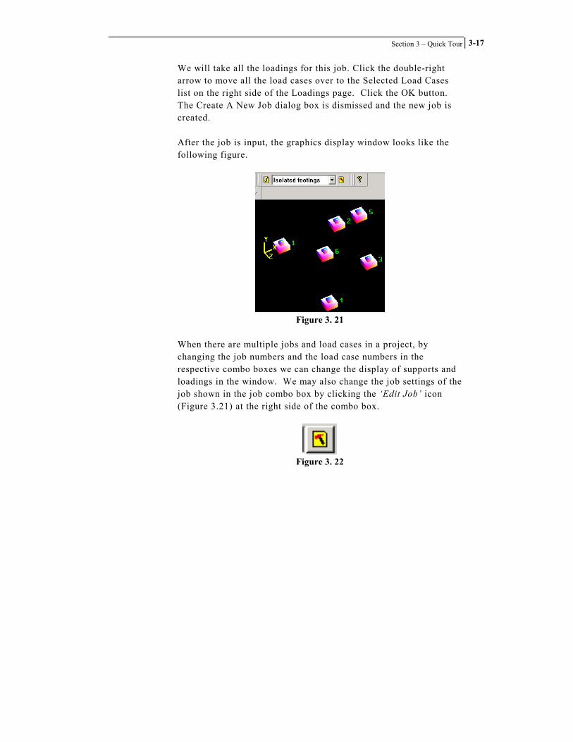
We will take all the loadings for this job. Click the double-right arrow to move all the load cases over to the Selected Load Cases list on the right side of the Loadings page. Click the OK button. The Create A New Job dialog box is dismissed and the new job is created. After the job is input, the graphics display window looks like the following figure.
Figure 3. 21
When there are multiple jobs and load cases in a project, by changing the job numbers and the load case numbers in the respective combo boxes we can change the display of supports and loadings in the window. We may also change the job settings of the job shown in the job combo box by clicking the ‘Edit Job’ icon (Figure 3.21) at the right side of the combo box.
Figure 3. 22

STAAD.foundation – User’s Manual
Section 3 – Quick Tour
3-18
3.6 Entering Design Parameters
When you begin a new project, only the Project Info, Foundation Plan and Loads and Factors page tabs will appear in the Page Control. These three tabs allow you to specify the physical model upon which the foundation design is to be performed. It is only when you specify a Job (a set of constraints for the program to use in performing a foundation design) that Page Control tabs related to the design process will appear. Now, take a look at the left-most splitter window. Two new tabs are now displayed there. They are “Design Parameters” and “Design”. The Design Parameters icons and forms are self-explanatory so we will not discuss them in this Quick Tour. Please note that in the present version of the software we must visit all the forms at least once to get them included in the job.
Figure 3. 23
Here is a very useful feature of STAAD.foundation. If we want to change the design parameters for a particular support we may change them locally by double-clicking on the support. Doing so invokes the local dialog box as shown below.

Section 3 – Quick Tour
3-19
Figure 3. 24

STAAD.foundation – User’s Manual
Section 3 – Quick Tour
3-20
3.7 Performing an Isolated Footing Design
If we click on the tab for “Design” the following set of icons comes up.
Figure 3. 25
The ‘Design’ button is for performing an optimized design of the footings. Click on the Design button. A dialog box labeled Optimize Uniformity will be displayed.
Figure 3. 26

Section 3 – Quick Tour
3-21
This dialog box allows you to specify an allowable percent increase in either area, thickness volume or reinforcing ratio. This allows the program to adjust the design so that standard size concrete forms may be used to construct the footing. Click the OK button. A message box will display a series of messages as the program performs the footing design.
Figure 3. 27
When the design is complete, click the Close button to dismiss the message box. The program will display a Design Summary table in the data area.
Figure 3. 28

STAAD.foundation – User’s Manual
Section 3 – Quick Tour
3-22
The ‘Footing Layout’ icon produces a layout of analyzed footings drawn to scale, complete with a title block for the drawing.
Figure 3. 29
The ‘Detailed Drawing’ icon brings up the details of the footings with the rebar diameter and spacing.
Figure 3. 30
A click on the ‘Calculation Sheet’ button brings up the design calculation of the footings.

Section 3 – Quick Tour
3-23
Figure 3. 31
This calculation sheet is web-enabled for real time checking. Hard copies can also be made from this sheet. A project once created can be saved and re-opened later using the File�Save and File�Open options. STAAD.foundation files are saved with .afs extension.

STAAD.foundation – User’s Manual
Section 3 – Quick Tour
3-24
3.8 Importing Structural Geometry and Analysis Results from STAAD.Pro
In most cases the forces and moments on the foundation are given by the analysis of the superstructure. To ensure a seamless and efficient integration with the analysis software STAAD.foundation includes an “Import” facility. This option allows us to import the support co-ordinates and forces/moments on the individual supports from a structural analysis software program. At present we have the facility to import analysis data from STAAD.Pro structural analysis software. Thus by default the control goes to the folder where STAAD.Pro example files are located. If you do not have STAAD.Pro installed in your machine please do not use the import facility now. The ability to import analysis data from other software programs will be provided in a future release of STAAD.foundation. Let us import STAAD.Pro US Example No. 8 to STAAD.foundation and use the imported geometry and support reactions to design a mat foundation for the structure. You can only import a STAAD.Pro model which has been successfully analyzed, because you will want to have the support reactions available for the foundation design. So, if you have not already run the analysis for STAAD.Pro U.S. Example No. 8 open the example in STAAD.Pro (C:\Spro2003\STAAD\Examp\US\Examp\ Examp08.std), run the analysis, then return to this Quick Tour.

Section 3 – Quick Tour
3-25
Pull down the File menu and select the Import command.
Figure 3. 32
A file manager dialog box labeled STAADPro File Import will be displayed.
Figure 3. 33
Locate the STAAD.Pro US Example No. 8 file and highlight it. Click on “Open”.

STAAD.foundation – User’s Manual
Section 3 – Quick Tour
3-26
Figure 3. 34
Click on Import in the resulting dialog box. The support coordinates will be imported to STAAD.foundation as shown in the graphics display window. Notice that you did not have to create a new project. STAAD.foundation did not overwrite the project you already had open, or add any new data to it. Instead, the program has created a new project with the default project name STAAD.foundation1.
Figure 3. 35

Section 3 – Quick Tour
3-27
3.9 Creating a New Job for a Mat Foundation
Click on the ‘New Job’ button to create a new job for designing the mat foundation. The Create a New Job dialog box will open.
Figure 3. 36
The job will be assigned to all the supports. We then include the loadings on it from the Loading page of the same property sheet.
Figure 3. 37

STAAD.foundation – User’s Manual
Section 3 – Quick Tour
3-28
If we look at the left-most window we see a set of tabs not seen in our previous project.
Figure 3. 38
The Meshing and Analysis” tabs are particular to the mat foundation. We also see the Property – Soil – Material tab. This tab only appears when when a project that contains beams has been opened or when a Mat Foundation job type is active.

Section 3 – Quick Tour
3-29
3.10 Setting up the Grid and Defining the Mat Boundary
Now we would like to define the boundary of the mat. To do this we click on the tab labeled “Meshing” and then on the ‘Grid’ icon. The following view comes up in the data area.
Figure 3. 39
The grid on your screen may or may not resemble the grid shown in the figure above. The program saves your previous grid settings as defaults, so your grid size will vary from that shown in the figure. We will use the grid to draw a polyline around our foundation supports. This polyline will define the location of the edge of our slab. The grid shown in the figure above is too small. We want our slab to extend beyond the centers of our six columns, and we want the slab to support all six columns. In order to draw our polyline, we need to expand the grid. We can do that by opening a Setup Grid dialog box.

STAAD.foundation – User’s Manual
Section 3 – Quick Tour
3-30
You will see a special toolbar at the bottom of the data area, as shown in the figure above. In the toolbar, you will see a square button labeled with an icon that looks like a grid. There is another, much smaller button with a down-pointing arrow just to the right of the grid button. Click on this small down-arrow button. A pop-up menu will appear.
Figure 3. 40
Select the Grid Setup command from this pop-up menu. The Setup Grid dialog box will be displayed.
Figure 3. 41

Section 3 – Quick Tour
3-31
The values shown in the Setup Grid dialog box are in units of inches. Looking at the plan view of our project, the footprint of our six columns is a rectangle 24 feet high by 38 feet wide.
Figure 3. 42
Let us suppose that we want our slab to extend two feet from the column centers all the way around the border of the slab. The Plan Setup category allows us to specify the origin of the grid with respect to our model’s global coordinate system, and to specify the plan that the grid is drawn in. We will leave the Plan Setup settings at their default values. The Construction Line category allows us to specify the location and spacing of our grid lines with respect to the grid’s origin. We will set the grid line Spacing to 24 inches. This will give us a grid line every two feet. We will also specify a value of 24 inches in the X – Left edit box. This tells the program that we want to draw lines parallel to the X axis starting 24 inches to the left of the grid origin. In addition we will specify a value of 24 inches in the Y – Top edit box. This tells the program that we want to draw lines parallel to the Y axis starting 24 inches above the grid origin. Now, to determine the values for the X – Right and Y – Bottom edit box settings, we need to convert the dimensions on our plan view from feet to inches, and add an extra two feet (24 inches) so that the slab extends two feet to the right of the right column centers in the X direction and two feet below the bottom in the Y direction.

STAAD.foundation – User’s Manual
Section 3 – Quick Tour
3-32
(38 ft. x 12 in.) + 24 in. = 480 in. ; (24 ft. x 12 in.) + 24 in. = 312 in. Enter a value of 480 in the X – Right edit box. Enter a value of 312 in the Y – Bottom edit box. Your Setup Grid dialog box should resemble the figure below.
Figure 3. 43
Click the OK button to dismiss the Setup Grid dialog box and re-plot the grid. Your grid should look similar to the figure below.
Figure 3. 44

Section 3 – Quick Tour
3-33
Now click on the Mat Boundary toolbar button.
Figure 3. 45
Hover your mouse cursor over the grid. The pointer will now display a flashing square box at the tip of your mouse arrow that will snap to each node on the grid.
Figure 3. 46
You can use this Mat Boundary Cursor to draw the boundary of your slab. Starting in the upper-left corner of your grid, click in sequence around the boundary, going in either clockwise or counter-clockwise order. Once you have clicked on all four corner points, return to your starting point and right-click on it. You will see a purple line defining the boundary you have created.
Figure 3. 47

STAAD.foundation – User’s Manual
Section 3 – Quick Tour
3-34
Now click on the Transfer Boundary arrow icon on the right side of the meshing toolbar.
Figure 3. 48
This action will transfer the boundary to the graphics display window.
Figure 3. 49
Now it would be a good idea to save your model, since you have done a substantial amount of work to get to this point. Pull down the File menu and select the Save command.
Section 3 – Quick Tour
3-35
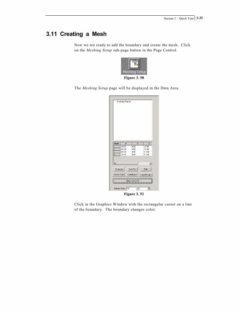
3.11 Creating a Mesh
Now we are ready to add the boundary and create the mesh. Click on the Meshing Setup sub-page button in the Page Control.
Figure 3. 50
The Meshing Setup page will be displayed in the Data Area.
Figure 3. 51
Click in the Graphics Window with the rectangular cursor on a line of the boundary. The boundary changes color.

STAAD.foundation – User’s Manual
Section 3 – Quick Tour
3-36
Click on the Boundary button. A dialog box labeled Mesh Identifier will be displayed.
Figure 3. 52
Enter a name for the boundary in the edit box labeled Identity of Mesh. The program does not allow spaces, or characters normally reserved for math operators (such as $, #, *, %, etc.) in the boundary name. Click the OK button. You will see that the Mesh Identifier name you entered is now listed under the Bounding Region heading in the list box.
Figure 3. 53

Section 3 – Quick Tour
3-37
We may also choose the number of divisions for the mesh and specify locations of holes. Let us specify an element size of 12 inches. Enter a value of 12 in the Element Size edit box. In this example project we will not create any holes in the mesh. We are ready to create the mesh. In the list box in the data area, highlight the Mesh Identifier Name for your mesh boundary.
Figure 3. 54
Click on the Create Mesh sub-page button in the Page Control.
Figure 3. 55
The program will display a dialog box asking you to choose either a Quadrilateral Mesh or a Polygonal Mesh.
Figure 3. 56

STAAD.foundation – User’s Manual
Section 3 – Quick Tour
3-38
Verify that the Quadrilateral Meshing radio button is selected by default, then click the OK button. STAAD.foundation will create the mesh and display it in the graphics window.
Figure 3. 57

Section 3 – Quick Tour
3-39
3.12 Specifying Slab Thickness
We are almost ready to analyze our foundation, but first we must tell the program how thick we want the slab to be. We do this by specifying the thickness of the plate elements that comprise the mesh. Click on the Property – Soil – Materials Page Control tab.
Figure 3. 58
Four sub-page icons will appear beneath the Property – Soil – Materials Page Control tab. Click on the Plate Thickness icon.
Figure 3. 59
The Plate Thickness page will be displayed in the data area.

STAAD.foundation – User’s Manual
Section 3 – Quick Tour
3-40
Figure 3. 60
A click on the Create New button brings up the New Plate Property dialog box where we input the plate thickness, corresponding units and the material of the plates.
Figure 3. 61

Section 3 – Quick Tour
3-41
Under the Plate Thickness category, enter a value of 1 ft in both the Analysis and Design edit boxes. Note that STAAD.foundation allows you to enter separate values for analysis and design if desired. Leave the Material set to Concrete. Click the OK button. The New Plate Property dialog box is dismissed and the 1 foot plate thickness property is added to the list in the data area.
Figure 3. 62
Let us use this same 1-foot thickness for all the plates. We keep selected the ‘Assign to All Regions’ radio button and click on the Assign button. Note that if you do not assign a thickness to the plates, the analysis will not be performed. Please note that we may introduce multiple thickness values using the ‘Create New’ button more than once. We may also edit the thickness value(s) entered by highlighting the thickness in the list box and clicking ‘Edit’. In the same way we may delete a thickness by highlighting it and clicking ‘Delete’.

STAAD.foundation – User’s Manual
Section 3 – Quick Tour
3-42
Figure 3. 63

Section 3 – Quick Tour
3-43
3.13 Defining Soil Properties
The last task required before performing the analysis is to define some soil properties. In the Page Control, click on the Soil Properties icon.
Figure 3. 64
The Soil Properties page will be displayed in the data area.
Figure 3. 65

STAAD.foundation – User’s Manual
Section 3 – Quick Tour
3-44
Click on the New Soil Support button. The Subgrade Modulus dialog box will open.
Figure 3. 66
You may enter a constant value for the soil subgrade modulus, or you may define it as a multilinear spring, where the modulus varies depending on the displacement of the slab. For this example exercise, we will use a constant value of 0.1 kip/in3 for the modulus of subgrade reaction. Verify that the Use Constant Value radio button is enabled by default, then enter a value of 0.1 kip/in3 in the edit box to the right of the Use Constant Value label. Click on the OK button. The Subgrade Modulus dialog box will be dismissed and you will see that the new soil property has been added to the list in the data area.

Section 3 – Quick Tour
3-45
3.14 Analyzing the Slab
We are ready to analyze the plates. Save your work one more time: pull down the File menu and select the Save command. Click on the Analysis Page Control tab.
Figure 3. 67
Now click on the button labeled Analyze.
Figure 3. 68
A dialog box will appear and messages will be displayed regarding the progress of the analysis.
Figure 3. 69

STAAD.foundation – User’s Manual
Section 3 – Quick Tour
3-46
When you see the messages have stopped scrolling, look for a final message, “Analyis is completed” which indicates that the analysis has been successfully performed. Click the Close button to dismiss the dialog box. You will notice that after the analysis is complete, three new Analysis sub-page buttons appear in the Page Control: Displacement, Support Reaction and Plate Stresses.
Figure 3. 70
You will also see that running the analysis has also caused a new tab to appear in the Page Control, the Slab Design tab.
Figure 3. 71

Section 3 – Quick Tour
3-47
By default the deformed plates showing the node displacements appear in the graphics display window.
Figure 3. 72
If the slab’s deformed shape is not apparent in your graphics display, you may need to change the scaling values. Pull down the View menu and select the Options command. The Set Viewing Options dialog box will be displayed. Click on the Scales tab.
Figure 3. 73

STAAD.foundation – User’s Manual
Section 3 – Quick Tour
3-48
Under the Result Scales category, decrease the Displacement value to increase the amount of deflection shown. Why do you decrease it to increase the deflection? The Displacement value in the dialog box is the actual displacement of the structure per unit distance on the graphic diagram. Therefore, if you reduce the amount of actual structural deflection required to display a unit distance of deflection on the diagram, you will see a larger apparent displacement on the diagram. Click on the Displacement sub-page button.
Figure 3. 74
You will see a Node Displacement table appear in the data area.
Figure 3. 75
This table lists the node displacement for the three translational and three rotational degrees of freedom. Please click on the ‘Support Reactions’ icon.
Figure 3. 76

Section 3 – Quick Tour
3-49
A report on support reactions will be shown in the forms window. To view the support reaction contour properly, click on the graphics window, then click on the icon shown in the figure below.
Figure 3. 77
Alternatively, you may pull down the View menu and select the Options command. Either way, the Set Viewing Options dialog box will open.
Figure 3. 78 Figure 3. 79
Click on the property page labeled Displacement. Toggle off the Show Nodal Displacement check box. Also, click on the Meshing tab and toggle off the Show Plates check box. Click the OK button. The Set Viewing Options dialog box will be dismissed and the screen will look like the following figure.

STAAD.foundation – User’s Manual
Section 3 – Quick Tour
3-50
Figure 3. 80
Click on the View From Top toobar button on the Rotate toolbar.
Figure 3. 81
The Support Reactions diagram will be re-plotted in plan view.
Figure 3. 82
Section 3 – Quick Tour
3-51
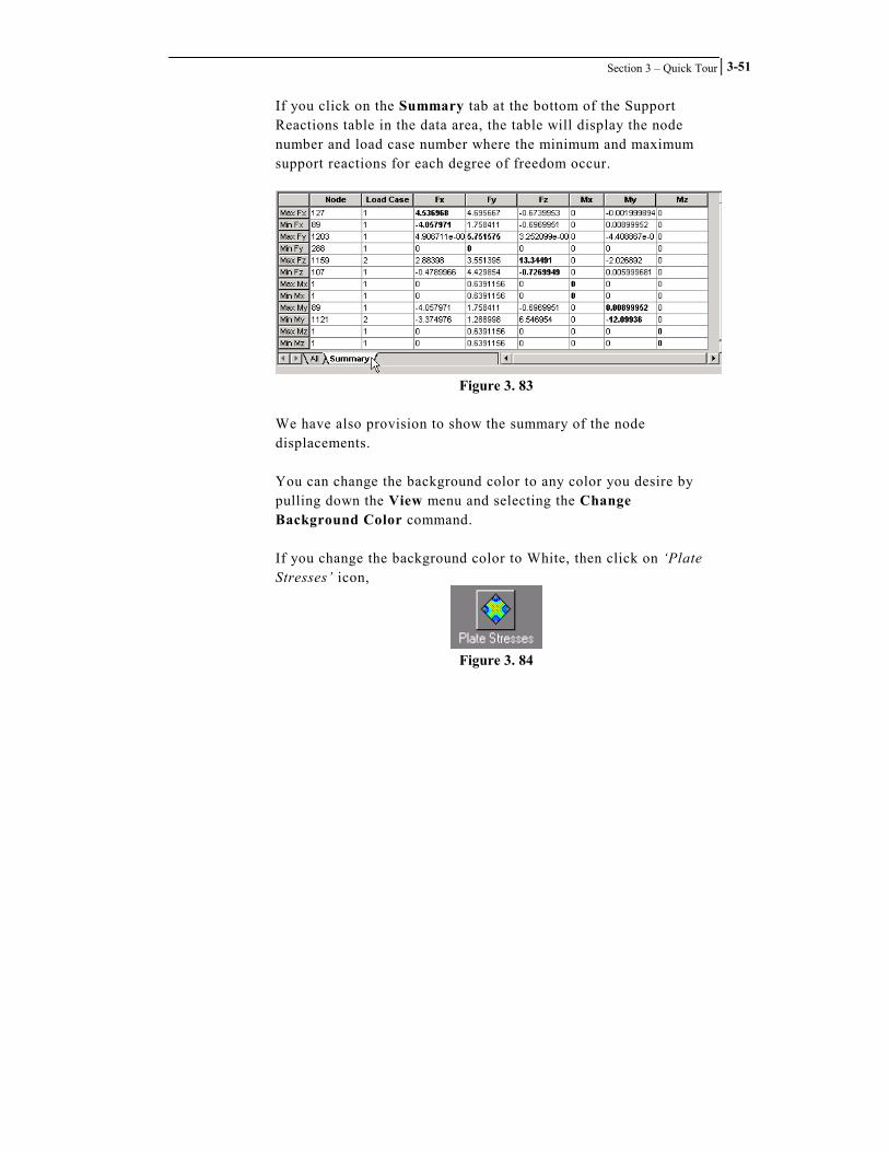
If you click on the Summary tab at the bottom of the Support Reactions table in the data area, the table will display the node number and load case number where the minimum and maximum support reactions for each degree of freedom occur.
Figure 3. 83
We have also provision to show the summary of the node displacements. You can change the background color to any color you desire by pulling down the View menu and selecting the Change Background Color command. If you change the background color to White, then click on ‘Plate Stresses’ icon,
Figure 3. 84

STAAD.foundation – User’s Manual
Section 3 – Quick Tour
3-52
the screen will look like the following figure.
Figure 3. 85

Section 3 – Quick Tour
3-53
3.15 Slab Design
Now we go for designing the slab. Click on the Slab Design tab.
Figure 3. 86
The Slab Design dialog box is displayed in the data area. Click on the Create Grid button.
Figure 3. 87

STAAD.foundation – User’s Manual
Section 3 – Quick Tour
3-54
A Work Progress dialog box appears as the program creates a design grid.
Figure 3. 88
When the Work Progress dialog box disappears, the design grid appears in the graphics window.
Figure 3. 89

Section 3 – Quick Tour
3-55
In the data area, click on the Design button.
Figure 3. 90
The program will perform the slab design. When the design operation is completed, a message box will appear.
Figure 3. 91

STAAD.foundation – User’s Manual
Section 3 – Quick Tour
3-56
Set the number of reinforcing zones to 2 by entering a a value of 2 in the No. of Zones edit box. Click on Create Reinforcing Zones button. The program will plot a colored dot in the center of each element of the mesh indicating the reinforcing zone that the element belongs to.
Figure 3. 92
Click on the Create Block button. STAAD.foundation will divide the slab into block-shaped areas, based on the reinforcement zones generated by the Create Reinforcing Zones command.
Figure 3. 93

Section 3 – Quick Tour
3-57
These rectangular areas are created to allow a practical layout of the various sizes of reinforcing steel.
Click on the Steel Detailing button. The following screen will come up showing the reinforcement steel details of the two zones while in the plan view.
Figure 3. 94
Click on the Slab Detailing sub-page button.
Figure 3. 95

STAAD.foundation – User’s Manual
Section 3 – Quick Tour
3-58
A detail drawing of the slab reinforcement design will be displayed in the graphics window.
Figure 3. 96
We may also cut the slab by any user defined line and view our desired stress value(Max absolute/Max VonMises/SX/SY etc.) along that line. Click on the sub-page button labeled Section Design Along a Line.
Figure 3. 97

Section 3 – Quick Tour
3-59
A new set of controls will appear in the data area.
Figure 3. 98
Under the Cutting Plan category, select the ZX radio button, then click in the graphics window. This will allow you to create a section in the plan view of your model. Enter a value of 3 in the Interpolation Factor edit box. Enter a value of 200 in the Graph Scale Factor edit box.

STAAD.foundation – User’s Manual
Section 3 – Quick Tour
3-60
In the Stress Type drop-down menu, select Max Absolute to look for maximum absolute stress along the cut line. Click on the button labeled Insert Cut Line. A dialog box with title Options for Cutting Mat by a Line will be displayed.
Figure 3. 99
Select the radio button labeled Cut by Drawing a Line. Click the OK button. The Cut by Drawing a Line dialog box will be dismissed. Now, draw a section line on the plan view of your model along which you wish to see the graph of the maximum absolute stress. Click your mouse cursor at the beginning point of the line, drag your cursor to the end point, then click again.

Section 3 – Quick Tour
3-61
Figure 3. 100
Now click on the button labeled View Cut Section. The following figure appears in the graphics window.
Figure 3. 101

STAAD.foundation – User’s Manual
Section 3 – Quick Tour
3-62
Now click the button labeled Design Selected Line. A dialog box labeled Design Report Along a Selected Line will be displayed.
Figure 3. 102
Click on the Design button to calculate the required reinforcement area for each element along the cut line.

Section 3 – Quick Tour
3-63
Figure 3. 103
Select the Close button to dismiss the Design Report Along a Selected Line dialog box. Save your work. Pull down the File menu and select the Save command.

STAAD.foundation – User’s Manual
Section 3 – Quick Tour
3-64
3.16 Pile Cap Example
Now let us create a new job inside this same project to illustrate the process for designing a pile cap. Create the new job: pull down the Tools menu and select the New Job command. The Create New Job dialog box will be displayed.
Figure 3. 104
Enter a name for the job in the New Job Name edit box. In the Job Type drop-down menu, select the Pile Cap job type. Click the OK button to dismiss the Create a New Job dialog box. Notice that your New Job Name now appears in the drop-down menu in the Jobs toolbar.
Figure 3. 105

Section 3 – Quick Tour
3-65
3.17 Entering Pile Data
For pile cap jobs, a unique tab called Pile Data will be created in the Page Control (the leftmost splitter window).
Figure 3. 106
Click on the Pile Data tab. Two sub-page buttons appear for input of pile arrangement data and pile design parameters:
• Pile Arrangement • Design Parameters
Figure 3. 107
Click on the Pile Arrangement sub-page button.
Figure 3. 108

STAAD.foundation – User’s Manual
Section 3 – Quick Tour
3-66
The Pile Arrangement page will be displayed in the data area.
Figure 3. 109
The combo box labeled Support for Pile Arrangement lists the support numbers in the pile cap job. We will select the support number and input the vertical, lateral and uplift pile capacities for each support. The pile diameter, spacing and distance of the edge from the corner piles are also input. Let us input data for Support No. 1. Leave the Support for Pile Arrangement drop-down menu set to 1. Under the Pile Capacity category, set the Unit drop-down menu to kip. Enter a value of 60 kips in the Vertical edit box, and a value of 40 kips in the Lateral and Uplift edit boxes.

Section 3 – Quick Tour
3-67
Enter a value of 10 in. for the Pile Dia. Enter a value of 36 in. for the Spacing. Enter a value of 24 in. for the Edge Distance. The total loading on the support is shown if we click on the Show Loading On Support button.
Figure 3. 110
We may either chose the Auto Arrangement or we may go for a manual input of the co-ordinates of the piles. If we choose Auto Arrangement and click on the Calculate button, all possible pile arrangements corresponding to the pile loads in all the load cases are shown according to the BOCA standard.
Figure 3. 111

STAAD.foundation – User’s Manual
Section 3 – Quick Tour
3-68
We go through the tree controls and choose the arrangement suitable to us. As we click on the OK button, the diagram showing the pile arrangements is transferred to the dialog box in the data area showing the input for pile arrangements. Please notice that the pile co-ordinates have come up in the corresponding table.
Figure 3. 112
If we click on the button for “Show Pile Reactions” the reaction on each pile shows up.

Section 3 – Quick Tour
3-69
Figure 3. 113
Depending on the pile arrangement diagram we may decide whether to go on with this arrangement or not. If we decide not to go on with the arrangement we would again click on Calculate. Otherwise we click on the Select Arrangement button to select the arrangement. Enter the Pile Arrangement data for the remaining supports in a similar fashion.

STAAD.foundation – User’s Manual
Section 3 – Quick Tour
3-70
3.18 Entering Pile Cap Design Parameters
After the pile arrangement is selected, the design for the pile cap is begun. The form for input of design parameters is invoked by clicking the Design Parameters sub-page button.
Figure 3. 114
The Design Parameters page will be displayed in the data area.
Figure 3. 115

Section 3 – Quick Tour
3-71
Let us accept the default parameters provided by the program. Check to make sure that the default values displayed on the Design Parameters form in your program match those shown in the figure above:
Strength of Concrete: 4 ksi Yield Strength of Steel: 60 ksi Minimum Bar Size: 6 Maximum Bar Size: 11 Side cover (Cs): 4 in Bottom Cover (Cb): 3 in Pile in Pile Cap (Cp): 4 in.

STAAD.foundation – User’s Manual
Section 3 – Quick Tour
3-72
3.19 Performing Pile Cap Design and Viewing Results
Now that the design parameters are entered, we are ready to perform the design. Click on the Design page control tab.
Figure 3. 116
Five sub-page buttons will be displayed below the design tab, just as we saw earlier when we were working with the Isolated Footing.
Figure 3. 117
Click on the Design sub-page button to perform the design.
Figure 3. 118

Section 3 – Quick Tour
3-73
The program performs the pile cap design. When it is finished, a results table appears in the data area showing the pile cap dimensions and the bar size and spacing in the longitudinal and transverse directions for all the supports designed.
Figure 3. 119
The figure above shows results for only three of the six supports in the project because pile arrangements were selected for only supports 6, 1 and 2, in that order. Unlike the other types of supports we looked at earlier, the pile cap specification pages do not have a facility to specify the pile cap, and then assign it to the view, or assign it to the specified supports, etc. You must go through the process of selecting a pile arrangement for every support you wish to design. Click on the Footing Layout sub-page button.
Figure 3. 120

STAAD.foundation – User’s Manual
Section 3 – Quick Tour
3-74
The layout of the pile cap job will show the different supports along with the pile arrangements and number of piles pertaining to them.
Figure 3. 121
Click on the Detailed Drawing sub-page button.
Figure 3. 122

Section 3 – Quick Tour
3-75
The following screen appears showing the plan of the pile cap, the details of the reinforcement bar for the pile cap and the front view of the pile cap along with the column for the support selected.
Figure 3. 123
Each part (e.g. PileCap Elevation) of the detailed drawing can be re-sized and re-positioned in the drawing sheet by selecting the part ,extending or reducing it and taking it by dragging the mouse to another part of the drawing. You may click on any detail item to highlight it, then drag it to any desired location. When you click on it, eight small square boxes are displayed on the border of each detail. These square boxes are “handles” that you can use to drag the sides and corners of the detail to change its size and shape.

STAAD.foundation – User’s Manual
Section 3 – Quick Tour
3-76
The Select SubEntity check box enables another set of handles that may be used to rearrange the drawing. When the Select SubEntity check box is toggled on, circular blue dots appear within each detail.
Figure 3. 124
These blue dots are also handles. You can click on these handles and drag them to move the annotation text and rearrange the callout arrows. The dialog box in the data area allows you to select a Design Group. STAAD.foundation creates a Design Group for each type of footing in the current job. When a job containing an Isolated Footing or Pile Cap job type is open and the Detail Drawing page is active, a dialog box similar to the one shown below will appear in the Data Area.
Figure 3. 125

Section 3 – Quick Tour
3-77
Each Design Group has its own detail drawing. Selecting a Design Group displays the corresponding detail drawing in the graphics window. The appearance of the drawing for each Design Group can be customized to suit your needs. A series of check boxes below the Design Group drop-down menu allows you to turn the various details on and off. The Select SubEntity dialog box turns on handles within each detail, so that you can rearrange the annotation and callout arrows.

STAAD.foundation – User’s Manual
Section 3 – Quick Tour
3-78
3.20 Exporting Drawings to CAD
Clicking on the DXF Export button exports the detail drawing into a DXF file, to allow you to import the drawing into a CAD program. Click on one of the details to highlight it, then click on the DXF Export button. The program will create the DXF file and display a message telling you the name and location of the file.
Figure 3. 126

Section 3 – Quick Tour
3-79
3.21 Local Footing Editing Features
As you may have noticed, in this example exercise we have used the same values of the design parameters for the pile caps corresponding to all the supports in the job. The user may, however, like to have different values of the parameters (e.g., different values of the maximum and minimum bar sizes) for different supports. We have introduced the concept of local dialog boxes to provide this flexibility to the user.
Click on the Design Summary sub page button.
Figure 3. 127
The foundation model will reappear in the graphics window.
Figure 3. 128

STAAD.foundation – User’s Manual
Section 3 – Quick Tour
3-80
If you double-click on any support in the graphics window, the local dialog box will appear.
Figure 3. 129
If you change the values in the Design Parameters dialog box and click on the OK button, the parameter values corresponding to that support will change. Save your work. Pull down the File menu and select the Save command.

Section 3 – Quick Tour
3-81
3.22 Conclusion
We hope you have enjoyed this Quick Tour of STAAD.foundation’s features and facilities. If you would like additional assistance in learning how to use STAAD.foundation, there are many resources available to you. Within the Online Help facility, you will find documentation describing the program theory and a detailed description of every command in the program. You may also view a number of animated movie files that demonstrate how to perform various tasks. Additional STAAD.foundation learning resources are available at Research Engineers’ web site at www.reiworld.com. Finally, we strongly encourage you to take advantage of REI’s technical support service. Our support staff is most eager and willing to help you learn to use the program correctly. You may contact our STAAD.foundation technical support staff by sending e-mail to the following address: [email protected] Write down your questions and attach your STAAD.foundation project file if you think it would be helpful (the STAAD.foundation project file is appended with the extension AFS – the current input file name always appears in the title bar at the top of your STAAD.foundation program window). Most technical support e-mails are answered the same day they are received. Thank you for purchasing STAAD.foundation. We hope you enjoy using the program and hope that it adds value and efficiency to your engineering endeavors. If you have any comments regarding the program, or suggestions on how it could be improved to better serve your needs, we would very much like to hear from you.

STAAD.foundation – User’s Manual
Section 3 – Quick Tour
3-82

4-1
STAAD.foundation Graphical Environment
This section includes discussion on the following topics:
• Introduction • Screen Organization • Page Control • Menu Commands • Toolbars
Section 4

STAAD.foundation – User’s Manual
Section 4 – Graphical Environment
4-2
4.1 Introduction
This section provides a description of STAAD.foundation’s graphical user interface (GUI). In STAAD.foundation, you start out by creating a Project to hold all your physical information, such as column locations, loads, etc. This physical information represents the structure that the foundation is intended to support. Unless the design of the structure is modified, these physical conditions generally remain constant throughout the life of the foundation design project. Your Project also contains Jobs, which are sets of constraints needed to tell the program how to perform a foundation design. Each project may contain multiple jobs, making it easy for you to evaluate different design scenarios for a given set of physical conditions. A project once created can be saved and re-opened later using the File�Save and File�Open options. STAAD.foundation files are saved with .afs extension. STAAD.foundation combines the menu-driven functionality of the Windows environment with a user-friendly split window functionality available in programs like Microsoft Outlook.

Section 4 – Graphical Environment
4-3
4.2 STAAD.foundation Screen Organization
The elements of the STAAD.foundation screen are identified in the figure below.
Figure 4. 1
Menu Bar
Located at the top of the screen, the menu bar gives access to all the facilities of STAAD.foundation. Many of these same functions are also available from the Toolbar and from the Page Control. Users who are familiar with STAAD.foundation and its commands usually find that the menu bar is the most efficient way for them to quickly access the commands they want. A complete description of the menu commands is provided in a subsequent section of this manual.

STAAD.foundation – User’s Manual
Section 4 – Graphical Environment
4-4
Toolbar The dockable toolbar gives access to the most frequently used commands. To control the appearance of the toolbar or create your own customized toolbar, pull down the View menu and select the Toolbar command.
Main View This is the largest area at the center of the screen, where the model and the results are displayed. This part of the screen is often referred to as the Graphics Window. You can use commands in the View pull-down menu and buttons on the Tools, Zoom and Rotate toolbars to alter the appearance of the main view. You can use the arrow keys to rotate the objects displayed in the main view. You can set the background to any desired color by pulling down the View menu and selecting the Change Background Color command. The Save Picture command in the File menu can be used to save the image shown in the main view in a bitmap (*.BMP) file.
Page Control The Page Control is a set of tabs with labels that appear on the left-most part of the screen. Each tab on the Page Control allows you to perform specific tasks. The organization of the page control tabs, from top to bottom, represents the logical sequence of operations such as definition of footing positions, specification of loads and factors, mesh generation controls, and so on. If you go through the pages from top to bottom and enter all the data that are relevant to your project, you will end up with a successful model. A detailed discussion of the facilities included in the Page Control is provided in a subsequent section of this manual.

Section 4 – Graphical Environment
4-5
Data Area Just to the right of the Page Control is the Data Area, where different dialog boxes, tables, list boxes, etc. appear depending on the type of operation you are performing. For example, when you select the Foundations Plan page control bar, then click on the Column Dimension button, a Column Dimension table is displayed in the Data Area; when you click on the Soil – Property – Material page control bar, then click on the Plate Thickness button, the contents of the Data Area changes to display the Plate Thickness dialog box, etc.
Status Bar A status bar is displayed at the bottom of the STAAD.foundation window. Helpful information regarding the status of the program is displayed here, including cursor position, current input units, current program operating mode, hints for using the program, etc.
Tool Tip Help The icons in the toolbar offer Tool Tip help, or Bubble Help as it is sometimes called. As you move the mouse pointer over a button, the name of the button – called a Tool Tip – appears above or below the button. This floating Tool Tip Help will identify the icon. A brief description of the icon also appears in the lower left corner of the status bar. To a limited degree, you can customize the appearance of the Tool Tip Help. Pull down the View menu and select the Tool Tip Options command. A dialog box will open to allow you to specify the type of information you would like the Tool Tip Help to display.

STAAD.foundation – User’s Manual
Section 4 – Graphical Environment
4-6
4.3 The Page Control The Page Control controls the display of dialog boxes for entering your project data. It is organized in a logical order, allowing you to complete a project by working from the top to the bottom. Each page has a horizontal page control tab labeled with the page name. Clicking on any page control tab moves it to the top of the Page Control. In addition, each page has from two to five sub-pages. Whenever you click on any of the page control tabs, the corresponding sub-page buttons appear directly below them. The Page Control tabs represent the major steps required to complete a foundation project. The sub-page buttons beneath each tab control the display of forms that appear in the data area. These forms provide you a convenient way to enter all data relevant to that aspect of the project. If you fill in all the forms under a particular page control tab, you will have successfully completed that step of the project. The pages and sub-pages in the Page Control, in order from top to bottom, are listed below. • Project Info
� General Info � Review History
• Foundation Plan
� Grid Setup � Column Position � Column Dimension � Pile for Mat Foundation � Physical Beams

Section 4 – Graphical Environment
4-7
• Loads and Factors
� Load Description � New Load Case � Load Combination � Remove Load Case � Safety Factors
• Meshing
� Meshing Grid � Meshing Setup � Create Mesh
• Property – Soil – Material
� Beam Property � Plate Thickness � Beam Offset � Soil Property
• Analysis
� Analyze � Displacement � Support Reaction � Plate Stresses
• Slab Design
� FEM Slab Design � Slab Detailing � Section Design Along a Line
Please note that the program does not display the entire set of page tabs all the time. Rather, it only displays tabs in the Page Control that are relevant to the current status of the project.

STAAD.foundation – User’s Manual
Section 4 – Graphical Environment
4-8
For example, when you begin a new project, only the Project Info, Foundation Plan and Loads and Factors page tabs will appear in the Page Control. These three tabs allow you to specify the physical model upon which the foundation design is to be performed. It is only when you specify a Job (a set of constraints for the program to use in performing a foundation design) that Page Control tabs related to the design will appear. Each Project may contain multiple Jobs.

Section 4 – Graphical Environment
4-9
4.3.1 The Project Info Page
The Project Info page is active by default when you open a new or existing project. You can also activate the Project Info page at any time by clicking on the Project Info tab in the Page Control.
Figure 4. 2
Use of the Project Info page is optional. It is provided for your convenience. You can store relevant general information regarding the project and also create a revision history. Later on, you can instruct the program to display this information in reports and drawings. When the Project Info page is active, two buttons appear directly below the Project Info tab:
• General Info • Review History

STAAD.foundation – User’s Manual
Section 4 – Graphical Environment
4-10
4.3.1.1 General Info
The General Info form is invoked by clicking the ‘General Info’ button beneath the “Project Info” tab.
Figure 4. 3
You may fill up the edit boxes shown in the form to store project-related data.
Figure 4. 4
Later you will be able to display these data automatically in report headers and drawing title blocks.

Section 4 – Graphical Environment
4-11
4.3.1.2 Review History
Figure 4. 5
Click on the ‘Review History’ icon to display a history table in the data area.
Figure 4. 6
A date, time, job name, originator and comments may be entered for each revision of the project. The comments for a given revision will be shown in the Comments box if we highlight the respective revision row. The Save button should be clicked after inserting any new revision history data to update the revision history table. If we want to delete a particular revision history record we highlight it by clicking on the respective Id and click the Delete button. If we want to delete the entire revision history we click on Delete All.

STAAD.foundation – User’s Manual
Section 4 – Graphical Environment
4-12
4.3.2 The Foundation Plan Page
The Foundation Plan page allows you to specify basic geometry for your foundation.
Figure 4. 7
When you click on the Foundation Plan page tab, five sub-page icons are displayed:
• Grid Setup • Column Positions • Column Dimensions • Pile for Mat Foundation • Physical Beams

Section 4 – Graphical Environment
4-13
4.3.2.1 Grid Setup
Figure 4. 8
When you click on the Grid Setup button, the Grid Setup dialog box is displayed in the data area.
Figure 4. 9

STAAD.foundation – User’s Manual
Section 4 – Graphical Environment
4-14
This dialog box is also displayed by default when you select the Foundation Plan Page Control tab. You may use this dialog box to draw a grid in the graphics area. The grid allows you to specify your foundation geometry by snapping to the intersections of the grid lines. You can control the location of the grid origin with respect to the global coordinate system. You can also specify the number of grid lines, and the spacing between lines. The grid lines may be spaced equally apart, or you can specify the spacing of each individual grid line. The values shown in the Grid Setup dialog box are in units of inches. You may use this dialog box to adjust the size, grid line spacing, and location of the origin of your grid.
Figure 4. 10

Section 4 – Graphical Environment
4-15
4.3.2.2 Column Positions
Figure 4. 11
The Column Positions button opens a spreadsheet table in the Data Area that allows you to input the position for each column in Cartesian (XYZ) coordinates.
Figure 4. 12
When the support coordinates are entered, the supports along with their respective node numbers are displayed in the Main View. The Tab key or the arrow keys may be used to move from one cell to the next in the table. Please note that a support will not be shown in the display window until we click on any of the cells in the row below it. The coordinates can be deleted or modified like any spreadsheet input.

STAAD.foundation – User’s Manual
Section 4 – Graphical Environment
4-16
4.3.2.3 Column Dimensions
Figure 4. 13
The Column Dimensions button opens a form for you to use in specifying the depth and width of the columns at each support location.
Figure 4. 14
Column dimensions are needed to check punching shear. Those are also needed to simulate a pedestal on the top of a mat etc.
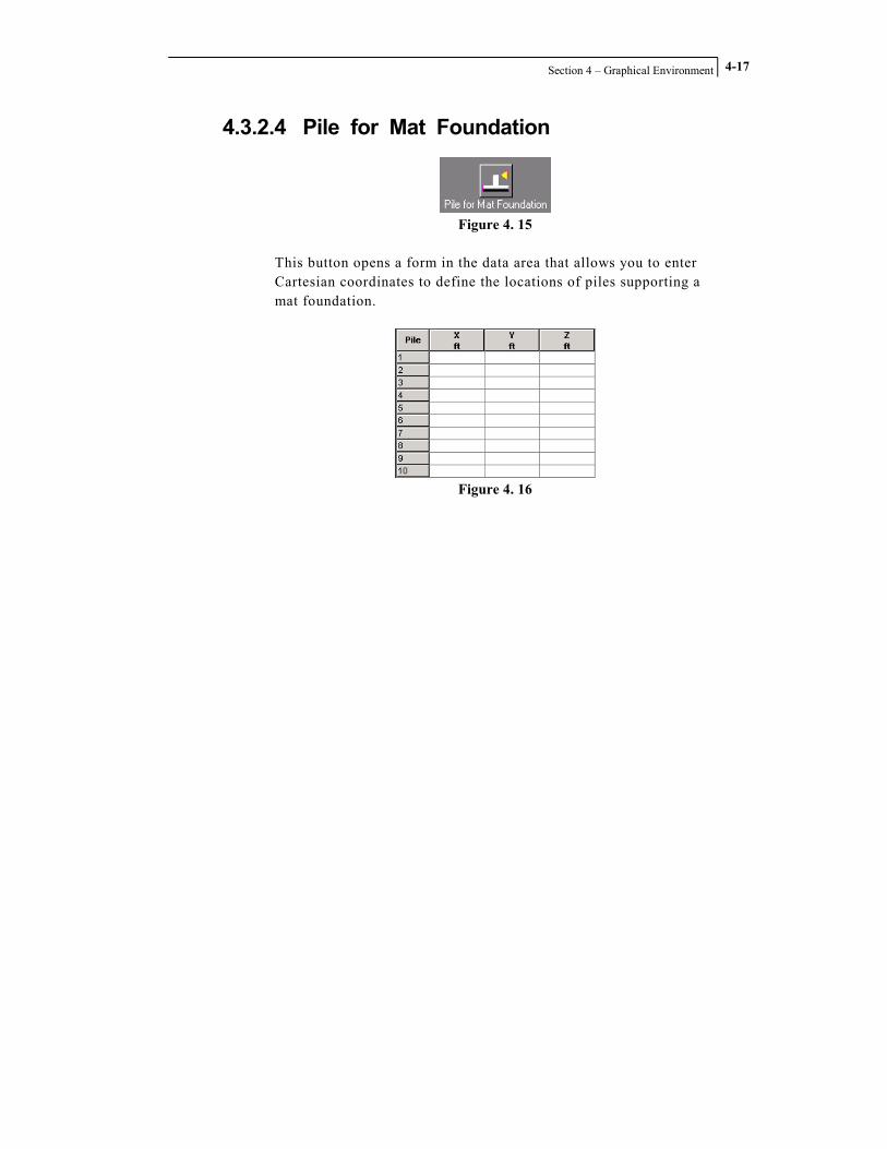
Section 4 – Graphical Environment
4-17
4.3.2.4 Pile for Mat Foundation
Figure 4. 15
This button opens a form in the data area that allows you to enter Cartesian coordinates to define the locations of piles supporting a mat foundation.
Figure 4. 16

STAAD.foundation – User’s Manual
Section 4 – Graphical Environment
4-18
4.3.2.5 Physical Beams
Figure 4. 17
Clicking on the Physical Beams button displays a form in the data area for specifying at-grade beams.
Figure 4. 18

Section 4 – Graphical Environment
4-19
4.3.3 The Loads and Factors Page
This page allows us to define the loads on our foundation.

STAAD.foundation – User’s Manual
Section 4 – Graphical Environment
4-20
4.3.3.1 Load Description
Figure 4. 19
Click this button to add a description to a load case.

Section 4 – Graphical Environment
4-21
4.3.3.2 New Load Case
Figure 4. 20
When you click on the New Load Case button, a dialog box labeled Create New Load Case will be displayed.
Figure 4. 21
Load Number
Default value is 1, increments automatically to the next higher integer each time you add a new load case, or you may specify any load number you wish.
Load Title
Load titles are optional. They help you identify the load conditions of a particular load case.
Load Type
You may specify a load type by selecting it from this drop down menu: "Primary", "Ultimate" or "Serviceability". In most cases,

STAAD.foundation – User’s Manual
Section 4 – Graphical Environment
4-22
you will use this dialog box to create new primary loads. However, if you happen to know what the ultimate load condition is, you can select the Ultimate load type and then enter the load values as a primary load case, instead of using the Load Combination option (discussed below) to create an ultimate load case by combining and factoring primary loads. Similarly, if you already know what the total service load values are, you can select the Serviceability load type and directly create a primary load case for it, rather than using the Load Combination option to create the serviceability load case by combining a set of individual primary loads. Click the Cancel button to dismiss the Create New Load Case dialog box without adding a new load case. Click the OK button to add the new load case to the list in the data area.
Figure 4. 22
To specify the types of loadings for each load case, highlight a load case in the load list, and then click on one of the five buttons below the list.

Section 4 – Graphical Environment
4-23
Column Reaction
Clicking on the Column Reaction button opens the Nodal Load dialog box.
Figure 4. 23
Specify the force and moment units using the drop down menus. Specify the magnitude of the forces and moments by entering values in the edit boxes. Click the OK button to dismiss the dialog box and add the load condition to the selected load case. Click the Close button to dismiss the dialog box without adding the load condition to the selected load case.

STAAD.foundation – User’s Manual
Section 4 – Graphical Environment
4-24
Point Load
This type of loading is applicable to the Mat Foundation only. Clicking on the Point Load button opens the Concentrated Load on Mat dialog box.
Figure 4. 24
Specify the force and moment units using the drop down menus under the Loading Unit category. Specify the magnitude of the forces and moments by entering values in the edit boxes under the Loading Values category. Define the loading position by entering the coordinates in the edit boxes under the Loading Position category. Click the OK button to dismiss the dialog box and add the load condition to the selected load case. Click the Cancel button to dismiss the dialog box without adding the load condition to the selected load case.

Section 4 – Graphical Environment
4-25
Member Load
This option is only available when beams are included in the project. If no beams are present, the Member Load button will be inactive (i.e., “grayed out”). Clicking on the Member Load button displays the Beam Loading dialog box.
Figure 4. 25
You may choose any of four loading types using the Loading Type drop-down menu in the Select Loading Type category:
• Concentrated • Uniform • Trapezoidal • Triangular
When you select a loading type, the edit box labels under the Loading category change to reflect the parameters needed to define the selected loading type. A diagram in the lower left corner of the Beam Loading dialog box illustrates how to use the parameters in the Loading category for each type of load.

STAAD.foundation – User’s Manual
Section 4 – Graphical Environment
4-26
Concentrated Loading
Uniform Loading
Trapezoidal Loading
Triangular Loading
Figure 4. 26 Select the units you want to use for defining the load position and magnitude using the Dist Force and Length drop-down menus in the Unit category. Use the radio buttons in the Direction category to define the direction in which the load will act. Click the OK button to dismiss the dialog box and add the load condition to the selected load case. Click the Cancel button to dismiss the dialog box without adding the load condition to the selected load case.

Section 4 – Graphical Environment
4-27
Quadrilateral Load
This type of loading is applicable to the Mat Foundation only. Clicking on this button opens the Quadrilateral Loading dialog box.
Figure 4. 27
You may use this dialog box to define a uniform pressure loading over an area defined by the four corners of a quadrilateral figure. Select the units you want to use for defining the load position and magnitude using the Dimension and Pressure drop-down menus in the Unit category. Enter the magnitude of the uniform load in the edit box labeled Pressure. Use the edit box under the Y Coord category to define the elevation at which the uniform loading is to be applied. Define the area or “footprint” of the loading by entering the coordinates of a quadrilateral figure in the edit boxes under the Loading Position category. Click the OK button to dismiss the dialog box and add the load condition to the selected load case. Click the Cancel button to dismiss the dialog box without adding the load condition to the selected load case.

STAAD.foundation – User’s Manual
Section 4 – Graphical Environment
4-28
Circular Load
This type of loading is applicable to the Mat Foundation only. When the Circular Load button is pressed, the Circular Load dialog box is displayed.
Figure 4. 28
You may use this dialog box to define a uniform pressure loading over a circular area. The program cannot actually create a true circular boundary, so it simulates the circle with a series of triangles that look like the wedges of a pie.
Figure 4. 29

Section 4 – Graphical Environment
4-29
Select the units you want to use for defining the load position and magnitude using the Dimension and Pressure drop-down menus in the Unit category. Enter the magnitude of the uniform load in the edit box labeled Pressure. Define the location of the circular load using the edit boxes under the Loading Position category. Enter the X and Z coordinates of the circle center in the Cx and Cz edit boxes. Enter the length of the circle radius in the Rad edit box. Use the Y Pos edit box to define the elevation at which the load is to be applied. Enter the number of pie-shaped triangular divisions you want the program to use to simulate the circular loading in the No. Of Divisions edit box.
10 Divisions
Figure 4. 30 Click the OK button to dismiss the dialog box and add the load condition to the selected load case. Click the Cancel button to dismiss the dialog box without adding the load condition to the selected load case.

STAAD.foundation – User’s Manual
Section 4 – Graphical Environment
4-30
4.3.3.3 Load Combination
Figure 4. 31
Selecting the Load Combination button displays a dialog box labeled Algebraic Combinations of Loads.
Figure 4. 32
With this dialog box, you can specify a load case that combines results of analysis performed for different primary load cases. Please note that this option combines algebraically the results of the analysis for the primary load cases. It does not analyze the structure for the combined loading.
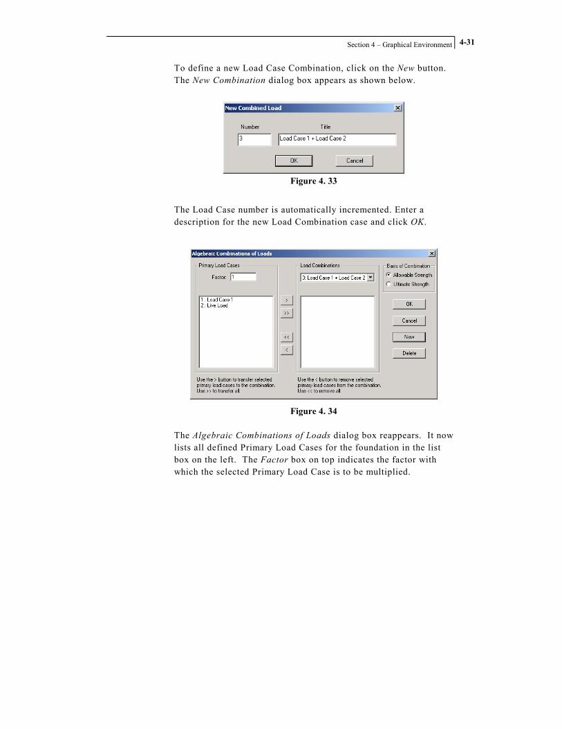
Section 4 – Graphical Environment
4-31
To define a new Load Case Combination, click on the New button. The New Combination dialog box appears as shown below.
Figure 4. 33
The Load Case number is automatically incremented. Enter a description for the new Load Combination case and click OK.
Figure 4. 34
The Algebraic Combinations of Loads dialog box reappears. It now lists all defined Primary Load Cases for the foundation in the list box on the left. The Factor box on top indicates the factor with which the selected Primary Load Case is to be multiplied.

STAAD.foundation – User’s Manual
Section 4 – Graphical Environment
4-32
To include a Primary Load Case, first select the load case from the list. Enter the multiplication factor in the Factor edit box. Click
the button to include the Primary Load Case in the Load Combinations specification. Continue for all primary load cases to
be combined. Use the button to include all Primary Load Cases, which will be multiplied by the specified factor.
To remove a Primary Load Case from the Load Combinations,
select the Load Case in the list box on the right and click the button. To remove all Primary Load Cases, click the button.

Section 4 – Graphical Environment
4-33
4.3.3.4 Remove Load Case
Figure 4. 35
Click on the Remove Load Case button to remove one or more load cases from your project. A dialog box labeled Remove Loadcase(s) will be displayed.
Figure 4. 36
Highlight the load case you wish to remove by clicking on it. You may click on additional load cases in the list to highlight them as well. Clicking once on any load case highlights it; click again to un-highlight it. When you have selected all the load cases you wish to remove, click the OK button. The dialog box will be dismissed and the program will remove the selected load cases from the project.

STAAD.foundation – User’s Manual
Section 4 – Graphical Environment
4-34
4.3.3.5 Safety Factors
Figure 4. 37
Clicking the Safety Factors button displays a table in the Data Area.
Figure 4. 38
The table contains a row labeled with the load case number for each load case in your project. You may enter a Serviceability Factor and a Design Factor for each load case in the project.

Section 4 – Graphical Environment
4-35
4.3.4 The Design Parameters Page
Figure 4. 39
The tab for this page appears in the Page Control only when an Isolated Footing job type has been activated. There are three sub-pages for the Design Parameters page:
• Concrete and Rebar • Cover and Soil • Geometry

STAAD.foundation – User’s Manual
Section 4 – Graphical Environment
4-36
4.3.4.1 Concrete and Rebar
Figure 4. 40
Clicking on the Concrete and Rebar button displays a Concrete and Rebar Properties table in the data area.
Figure 4. 41
The Concrete and Rebar sub-page is also activated by default when you select the Design Parameters Page Control tab.

Section 4 – Graphical Environment
4-37
You may enter design parameters as follows:
• Unit Weight of Concrete • Strength of Concrete • Yield Strength of Reinforcing Steel • Minimum Bar Size • Maximum Bar Size • Minimum Bar Spacing • Maximum Bar Spacing • Reinforcement Type
If you want the program to save the values you enter to use as default values in future projects, toggle on the check box labeled Set as Default.

STAAD.foundation – User’s Manual
Section 4 – Graphical Environment
4-38
4.3.4.2 Cover and Soil
Figure 4. 42
When the Cover and Soil button is selected, a worksheet with title Cover and Soil is displayed in the data area as shown below.
Figure 4. 43

Section 4 – Graphical Environment
4-39
You may enter clear cover and parameters and soil characteristic data as follows:
• Pedestal Clear Cover • Footing Clear Cover • Unit Weight of Soil • Soil Bearing Capacity • Depth of Soil • Surcharge for Loading
If you want the program to save the values you enter to use as default values in future projects, toggle on the check box labeled Set as Default.

STAAD.foundation – User’s Manual
Section 4 – Graphical Environment
4-40
4.3.4.3 Geometry
Figure 4. 44
Clicking on the Geometry button brings up the following dialog box:
Figure 4. 45
The Footing Details category provides you with the option to instruct the program to calculate the footing dimensions, or you can specify a desired Thickness, Length, and/or Width by toggling on the appropriate check box and entering the desired values in the

Section 4 – Graphical Environment
4-41
corresponding edit boxes. The program will calculate any value left unspecified for you. If you toggle on the Include Pedestal check box in the upper left corner of the dialog box, the Pedestal Details category will be activated. You may select either a rectangular or round pedestal. Then you may enter geometry data for the pedestal length, width and height, and also specify offset distances if you wish the pedestal to be offset from the center of the footing. The program will set default values for the pedestal length and width equal to the column dimensions for the selected footing. If you want the program to save the values you enter to use as default values in future projects, toggle on the check box labeled Set as Default.

STAAD.foundation – User’s Manual
Section 4 – Graphical Environment
4-42
4.3.5 The Pile Data Page
Figure 4. 46
The tab for this page appears in the Page Control only when a Pile Cap job type has been activated. There are two sub-pages for the Pile Data page:
• Pile Arrangement • Design Parameters
The Pile Arrangement sub-page allows you to define the spatial arrangement of the piles. The Design Parameters sub-page is used for entering control data such as strength of concrete, strength of steel, etc.

Section 4 – Graphical Environment
4-43
4.3.5.1 Pile Arrangement
Figure 4. 47
Clicking on the Pile Arrangement button displays a worksheet in the data area. The Pile Arrangement sub-page is also activated by default when the Pile Data tab is selected from the Page Control.
Figure 4. 48
You may use this worksheet to enter physical data for the program to use in designing the pile caps.

STAAD.foundation – User’s Manual
Section 4 – Graphical Environment
4-44
Support for Pile Arrangement
Use the Support for Pile Arrangement drop down menu to select any of the supports in the current job for which a pile cap support type has been defined (use the Create New Job or Edit Job commands to define or change the supports listed in this drop down menu).
Pile Capacity
Select the force units from the Unit drop-down menu. Enter force values for the Vertical, Lateral and Uplift forces that the pile is meant to bear. Enter the pile diameter, spacing between piles and edge distance.
Show Loading On Support
The total loading on the support is shown when you click on the Show Loading On Support button.
Figure 4. 49
You may then either ask the program to calculate the pile arrangement, or you may define it yourself. To have the program calculate the pile arrangement, click the Auto Arrangement radio button, and then click on the Calculate button.
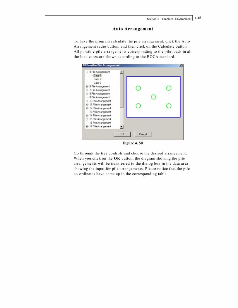
Section 4 – Graphical Environment
4-45
Auto Arrangement
To have the program calculate the pile arrangement, click the Auto Arrangement radio button, and then click on the Calculate button. All possible pile arrangements corresponding to the pile loads in all the load cases are shown according to the BOCA standard.
Figure 4. 50
Go through the tree controls and choose the desired arrangement. When you click on the OK button, the diagram showing the pile arrangements will be transferred to the dialog box in the data area showing the input for pile arrangements. Please notice that the pile co-ordinates have come up in the corresponding table.

STAAD.foundation – User’s Manual
Section 4 – Graphical Environment
4-46
Figure 4. 51
Manual Arrangement
To enter the pile arrangement manually, click on the Manual Arrangement button, and then enter the pile cap coordinates in the table. Note that these are local coordinates for the footing, relative to the center of the footing.
Show Pile Reactions
When you click on the Show Pile Reactions button, a table pops open showing the reaction on each pile.
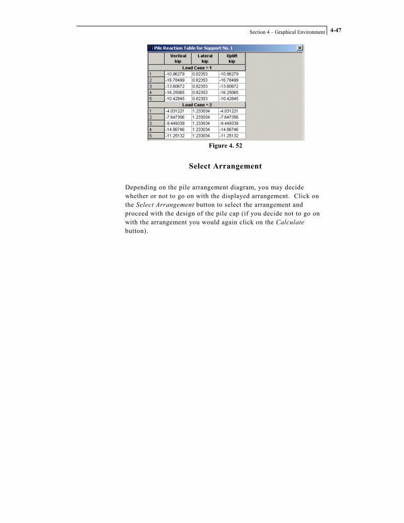
Section 4 – Graphical Environment
4-47
Figure 4. 52
Select Arrangement
Depending on the pile arrangement diagram, you may decide whether or not to go on with the displayed arrangement. Click on the Select Arrangement button to select the arrangement and proceed with the design of the pile cap (if you decide not to go on with the arrangement you would again click on the Calculate button).

STAAD.foundation – User’s Manual
Section 4 – Graphical Environment
4-48
4.3.5.2 Design Parameters
Figure 4. 53
Click on the Design Parameters button to display the Design Parameters worksheet in the data area.
Figure 4. 54
This worksheet allows you to enter the standard design control parameters for the program to use in designing the pile cap. The Pile in Pile Cap parameter refers to the length of the pile that is contained within the pile cap, as shown by the Cp parameter in the diagram at the top of the Design Parameters dialog box.

Section 4 – Graphical Environment
4-49
4.3.6 The Design Page
Figure 4. 55
The Design tab appears in the Page Control only when an Isolated Footing or Pile Cap job type has been activated. The Design page contains five sub-pages:
• Design • Design Summary • Footing Layout • Detailed Drawing • Calculation Sheet

STAAD.foundation – User’s Manual
Section 4 – Graphical Environment
4-50
4.3.6.1 Design
Figure 4. 56
When all project data and design parameters have been input, clicking the Design button instructs the program to actually perform the foundation design.
Isolated Footing Design
A dialog box labeled Optimize Uniformity will be displayed.
Figure 4. 57
This dialog box allows you to specify an allowable percent increase in either area, thickness volume or reinforcing ratio. This allows the program to adjust the design so that uniform size concrete forms may be used to construct the footing. Without optimizing the design, the program might specify a different size footing for each support in the project, requiring a separate form for each footing.

Section 4 – Graphical Environment
4-51
Click the OK button. A message box will display a series of messages as the program performs the Isolated Footing design.
Figure 4. 58
When the design is complete, click the Close button to dismiss the message box. The program will automatically activate the Design Summary page and display a results table in the data area.
Figure 4. 59

STAAD.foundation – User’s Manual
Section 4 – Graphical Environment
4-52
Pile Cap Design
The program performs the pile cap design as soon as you click on the Design button. When it is finished, the Design Summary page is automatically activated and a results table appears in the data area.
Figure 4. 60
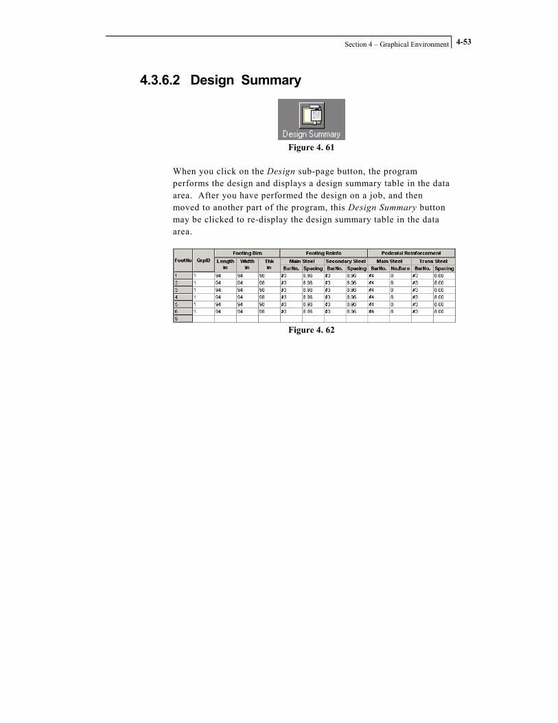
Section 4 – Graphical Environment
4-53
4.3.6.2 Design Summary
Figure 4. 61
When you click on the Design sub-page button, the program performs the design and displays a design summary table in the data area. After you have performed the design on a job, and then moved to another part of the program, this Design Summary button may be clicked to re-display the design summary table in the data area.
Figure 4. 62

STAAD.foundation – User’s Manual
Section 4 – Graphical Environment
4-54
4.3.6.3 Footing Layout
Figure 4. 63
The Footing Layout icon produces a layout of analyzed footings drawn to scale, complete with a title block for the drawing.
Figure 4. 64

Section 4 – Graphical Environment
4-55
4.3.6.4 Detailed Drawing
Figure 4. 65
The Detailed Drawing icon brings up the details of the footings with the rebar diameter and spacing, and also pile cap dimensions in the case of a pile cap design.
Figure 4. 66
You may rearrange the drawing to suit your needs. You may click on any detail item to highlight it, and then drag it to any desired location. When you click on it, eight small square boxes are displayed on the border of each detail. These square boxes are “handles” that you can use to drag the sides and corners of the detail to change its size and shape. The Select SubEntity check box enables another set of handles that may be used to rearrange the drawing. When the Select SubEntity check box is toggled on, circular blue dots appear within each detail.
Figure 4. 67

STAAD.foundation – User’s Manual
Section 4 – Graphical Environment
4-56
These blue dots are also handles. You can click on these handles and drag them to move the annotation text and rearrange the callout arrows. The dialog box in the data area allows you to select a Design Group. STAAD.foundation creates a Design Group for each type of footing in the current job. When a job containing an Isolated Footing or Pile Cap job type is open and the Detail Drawing page is active, a dialog box similar to the one shown below will appear in the Data Area.
Figure 4. 68
Each Design Group has its own detail drawing. Selecting a Design Group displays the corresponding detail drawing in the graphics window. The appearance of the drawing for each Design Group can be customized to suit your needs. A series of check boxes below the Design Group drop-down menu allows you to turn the various details on and off. The Select SubEntity dialog box turns on

Section 4 – Graphical Environment
4-57
handles within each detail, so that you can rearrange the annotation and callout arrows.
DXF Export
Clicking on the DXF Export button exports the detail drawing into a DXF file, to allow you to import the drawing into a CAD program. Click on any one of the details to highlight it, and then click on the DXF Export button. The program will create the DXF file and display a message telling you the name and location of the file.
Figure 4. 69

STAAD.foundation – User’s Manual
Section 4 – Graphical Environment
4-58
4.3.6.5 Calculation Sheet
Figure 4. 70
A click on the Calculation Sheet button brings up the design calculation of the footings. This calculation sheet is web-enabled for real time checking. Hard copies can also be made from this sheet.
Figure 4. 71

Section 4 – Graphical Environment
4-59
4.3.7 The Meshing Page
Figure 4. 72
The Meshing tab appears in the Page Control only when a job containing a Mat Foundation job type is active.
When you click on the Meshing tab, three sub-page buttons appear in the Page Control:
• Meshing Grid • Meshing Setup • Create Mesh These controls are used to define the location and construction parameters of the finite element mesh that STAAD.foundation uses to model foundation slabs. Finite Element Analysis is commonly applied to surface-type structures such as walls, slabs, plates and shells. The structure is represented by a series or mesh of connected elements. The method allows the displacements of the structure to be determined only at the corners of each element, and the stresses to be determined at the center of each element. To accurately model the behavior of a structure under load, it is important to take care in constructing the mesh, so that sufficient data are available in the areas where maximum stresses and/or displacements occur. The meshing controls will assist you to do that. A discussion of items to consider when constructing a mesh is presented in the Theoretical Basis section of this documentation.

STAAD.foundation – User’s Manual
Section 4 – Graphical Environment
4-60
4.3.7.1 Meshing Grid
Figure 4. 73
When you click on the Meshing Grid sub-page button, a grid with your foundation supports superimposed on it appears in the data area.
Figure 4. 74
You will see a special Meshing Grid toolbar at the bottom of the data area.
Figure 4. 75

Section 4 – Graphical Environment
4-61
Toolbar Auto-hide
This button toggles the toolbar Auto-hide feature on and off. Clicking on the button activates the toolbar so that it is always visible at the bottom of the data area. Clicking the button again puts the toolbar in Auto-hide mode. In this mode, the toolbar only appears when you hover your mouse cursor at the bottom of the data area. Auto-hide mode is desirable when you want to maximize the size of the grid area on your screen.
Show/Hide Grid
This toolbar button is a toggle. Clicking it once causes the grid to appear. Clicking it a second time hides the grid.
Define Grid Size
When you click on this small down-arrow button, a pop-up menu will appear.
Figure 4. 76
When you select the Grid Setup command from this pop-up menu, the Setup Grid dialog box will be displayed.
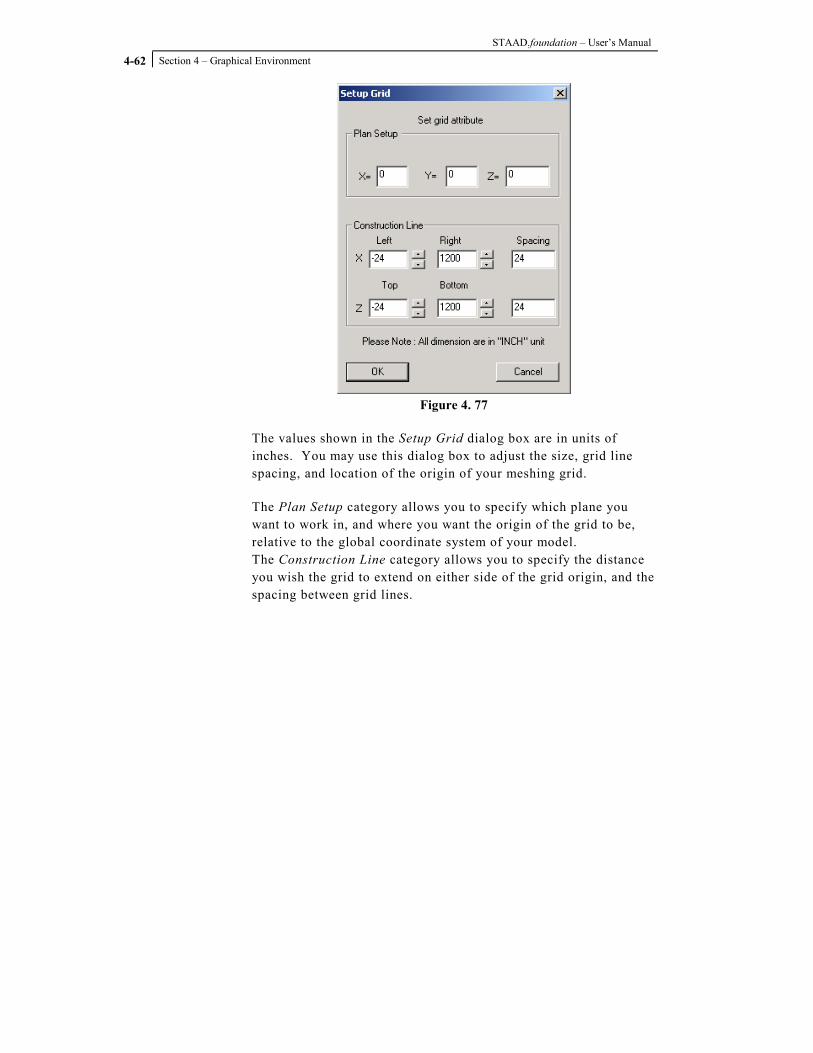
STAAD.foundation – User’s Manual
Section 4 – Graphical Environment
4-62
Figure 4. 77
The values shown in the Setup Grid dialog box are in units of inches. You may use this dialog box to adjust the size, grid line spacing, and location of the origin of your meshing grid.
The Plan Setup category allows you to specify which plane you want to work in, and where you want the origin of the grid to be, relative to the global coordinate system of your model. The Construction Line category allows you to specify the distance you wish the grid to extend on either side of the grid origin, and the spacing between grid lines.

Section 4 – Graphical Environment
4-63
Mat Boundary
The Mat Boundary toolbar button is used to draw on the grid a polyline representing the edge of your slab.
Figure 4. 78
When you click on the Mat Boundary toolbar button and hover your mouse cursor over the grid, the pointer will display a flashing square box at the tip of your mouse arrow that will snap to each node on the grid.
Figure 4. 79
You can use this Mat Boundary Cursor to draw the boundary of your slab. Click in sequence around the boundary, going in either clockwise or counter-clockwise order. Once you have clicked on all the points that define the boundary of your slab, return to your starting point and right-click on it. You will see a purple line defining the boundary you have created.

STAAD.foundation – User’s Manual
Section 4 – Graphical Environment
4-64
Figure 4. 80
Add Node
Allows you to place a node within your grid. You may use this node later with the Auto-region feature to create control regions automatically, based on Column Dimensions that you entered in the Foundation Plan page. Control Regions are used to define different areas of the slab, so that you can specify separate slab thickness for each region.
Circular Boundary
This tool allows

Section 4 – Graphical Environment
4-65
Pan
This tool allows you to move the grid from side to side and up and down in the data area (there is also a Pan tool in the Zoom toolbar, but the tools on the Zoom toolbar are used to alter the view in the graphics window).
Zoom In
Makes the scale of the grid display larger so that you appear to move closer to the grid so that you can see the grid objects in the data area in greater detail (there is also a Zoom In tool in the Zoom toolbar, but the tools on the Zoom toolbar are used to alter the view in the graphics window).
Zoom Out
Makes the scale of the grid display smaller so that you appear to move higher above the grid so that you can see more of it (there is also a Zoom Out tool in the Zoom toolbar, but the tools on the Zoom toolbar are used to alter the view in the graphics window).
Delete Boundary
Create Control Region

STAAD.foundation – User’s Manual
Section 4 – Graphical Environment
4-66
Transfer Boundary
The Transfer Boundary toolbar button is used to transfer boundaries that you have drawn on the grid into the main view of your model.
Figure 4. 81
Figure 4. 82

Section 4 – Graphical Environment
4-67
4.3.7.2 Meshing Setup
Figure 4. 83
When you click on the Meshing Setup sub-page button, the Meshing Setup page will be displayed in the Data Area.
Figure 4. 84
A list box at the top of this page displays the names of all boundary regions you have defined in the job.

STAAD.foundation – User’s Manual
Section 4 – Graphical Environment
4-68
Boundary button
Click on this button to define a new boundary for your mat foundation. You may define multiple boundaries for each job. A dialog box labeled Mesh Identifier will be displayed.
Figure 4. 85
Enter a name for the boundary in the edit box labeled Identity of Mesh. The program does not allow spaces, or characters normally reserved for math operators (such as $, #, *, %, etc.) in the boundary name. Click the OK button. You will see that the Mesh Identifier name you entered is now listed under the Bounding Region heading in the list box.

Section 4 – Graphical Environment
4-69
Figure 4. 86
You may also choose the number of divisions for the mesh and specify locations of holes.

STAAD.foundation – User’s Manual
Section 4 – Graphical Environment
4-70
4.3.7.3 Create Mesh
Figure 4. 87
The program will display a dialog box asking you to choose either a Quadrilateral Mesh or a Polygonal Mesh.
Figure 4. 88
A Quadrilateral Mesh works well for slabs with rectangular boundaries, or boundaries where the corners form 90-degree angles, like T-shaped slabs, L-shaped slabs, etc. A Polygonal Mesh is the better choice for slabs with irregular shapes, like a Y-shaped slab, or slabs with round holes, irregular-shaped holes, round edges, etc. Select the desired Meshing Type, and then click the OK button. STAAD.foundation will create the mesh and display it in the graphics window.
Figure 4. 89

Section 4 – Graphical Environment
4-71
4.3.8 The Property – Soil – Material Page
Figure 4. 90
The Property – Soil – Material tab appears in the Page Control only when a project containing one or more beams is open, or when a job containing a Mat Foundation job type is active. The Property – Soil – Material Page contains four sub-pages: • Beam Properties • Plate Thickness • Beam Offset • Soil Properties

STAAD.foundation – User’s Manual
Section 4 – Graphical Environment
4-72
4.3.8.1 Beam Properties
Figure 4. 91
If there are beams defined in the project, clicking on the Beam Property dialog box will display the Beam Property page in the data area.
Figure 4. 92
Create New
Click on the Create New button to add a beam property specification to the list box at the top of the Beam Property page. When you click the Create New button, the Create Member Property dialog box appears.

Section 4 – Graphical Environment
4-73
Figure 4. 93
Enter the member width and depth, and specify the material, then click the OK button. The properties you specified will appear as a single-item entry in the list box.
Figure 4. 94
You may create as many items as desired. You may then highlight a desired item and use the controls under the Assignment Method category to assign the listed item’s properties to a beam or beams in the model.

STAAD.foundation – User’s Manual
Section 4 – Graphical Environment
4-74
Assignment Method
This category is used to assign member properties shown in the list box to members in your model. • When the Assign to All Beams radio button is active, clicking
on the Assign button assigns the selected item in the properties list to all members in the model.
• To use the cursor to assign properties, click on the Assign to the Selected Beams radio button, highlight the desired property item in the list, click on the members in the model you wish to assign that item to, and then click on the Assign button.
• You can assign properties by member number. Highlight the desired property item in the list, click on the Assign to the Listed Beams radio button, type the member numbers in the edit box, and then click on the Assign button.

Section 4 – Graphical Environment
4-75
4.3.8.2 Plate Thickness
Figure 4. 95
The Plate Thickness page allows you to specify the element thickness for the plate elements in the mesh you are using to model your mat foundation. When you click on the Plate Thickness sub-page button, the Plate Thickness page is displayed in the data area.
Figure 4. 96

STAAD.foundation – User’s Manual
Section 4 – Graphical Environment
4-76
Create New
A click on the Create New button brings up the New Plate Property dialog box. You may use this dialog box to input the plate thickness, corresponding units and the material of the plates.
Figure 4. 97
You may enter the desired plate thickness and material. Note that STAAD.foundation allows you to enter separate values for analysis and design if desired. Click the OK button to dismiss the New Plate Property dialog box and add the plate thickness property to the list in the data area.
Figure 4. 98
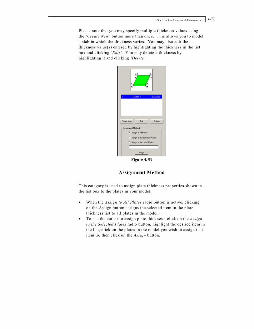
Section 4 – Graphical Environment
4-77
Please note that you may specify multiple thickness values using the ‘Create New’ button more than once. This allows you to model a slab in which the thickness varies. You may also edit the thickness value(s) entered by highlighting the thickness in the list box and clicking ‘Edit’. You may delete a thickness by highlighting it and clicking ‘Delete’.
Figure 4. 99
Assignment Method
This category is used to assign plate thickness properties shown in the list box to the plates in your model. • When the Assign to All Plates radio button is active, clicking
on the Assign button assigns the selected item in the plate thickness list to all plates in the model.
• To use the cursor to assign plate thickness, click on the Assign to the Selected Plates radio button, highlight the desired item in the list, click on the plates in the model you wish to assign that item to, then click on the Assign button.

STAAD.foundation – User’s Manual
Section 4 – Graphical Environment
4-78
• You can assign properties by plate number. Highlight the desired property item in the list, click on the Assign to the Listed Plates radio button, type the plate numbers in the edit box, and then click on the Assign button.
Note: If you do not assign thickness properties to all the plates in your model, the analysis will not be performed.

Section 4 – Graphical Environment
4-79
4.3.8.3 Beam Offset
Figure 4. 100
The Beam Offset page allows you to model the geometry of beams that are offset from their connection points. When you click on the Beam Offset sub-page button, the Member Offset specification page is displayed in the data area.
Figure 4. 101
Create New
Click on the Create New button to add a member offset specification to the list box at the top of the Member Offset specification page. When you click the Create New button, a dialog box labeled Offset Particulars appears.

STAAD.foundation – User’s Manual
Section 4 – Graphical Environment
4-80
Figure 4. 102
The Offset Location category allows you to specify the end of the member at which the offset is to be applied. The Starting End and Ending End of the member refers to the member incidence list, and depends on the order in which the nodes to which the member connects were originally specified. If you are not sure which end is the Start end of a particular member, you can highlight the member and then hover your mouse cursor over it. STAAD.foundation’s tool tip help will display the member connectivity information, as shown in the figure below.
Figure 4. 103

Section 4 – Graphical Environment
4-81
Node A is the starting end and Node B is the ending end. The Offset Magnitude category allows you to specify the distance in the X, Y and/or Z direction that the member is offset from the node. Click the OK button to dismiss the Offset Particulars dialog box and add the plate thickness property to the list in the data area.
Assignment Method
This category is used to assign member offset properties shown in the list box to members in your model. • When the Assign to All Beams radio button is active, clicking
on the Assign button assigns the selected item in the properties list to all members in the model.
• To use the cursor to assign properties, click on the Assign to the Selected Beams radio button, highlight the desired beam offset in the list, click on the members in the model you wish to assign that item to, then click on the Assign button.
• You can assign offsets by member number. Highlight the desired offset property item in the list, click on the Assign to the Listed Beams radio button, type the member numbers in the edit box, then click on the Assign button.

STAAD.foundation – User’s Manual
Section 4 – Graphical Environment
4-82
4.3.8.4 Soil Properties
Figure 4. 104
The Soil Properties page may be used to specify the soil properties for the design of mat foundations and pile supports. When you click on the Soil Properties sub-page button, the Soil Properties page will be displayed in the data area.
Figure 4. 105

Section 4 – Graphical Environment
4-83
New Soil Support
When you click on the New Soil Support button, the Subgrade Modulus dialog box will open.
Figure 4. 106
You may enter a constant value for the soil subgrade modulus, or you may define it as a multilinear spring, where the modulus varies depending on the displacement of the slab. Click on the OK button to dismiss the Subgrade Modulus dialog box and add the new soil property to the list on the Soil Properties page.
New Pile Support
When you click on the New Pile Support button, the Define Pile Spring dialog box will open.

STAAD.foundation – User’s Manual
Section 4 – Graphical Environment
4-84
Figure 4. 107
You may enter a spring constant K value for any or all three of the translational degrees of freedom. Click on the OK button to dismiss the Define Pile Spring dialog box and the new soil property will be added to the list on the Soil Properties page.
Assignment Method
This category is used to assign soil properties shown in the list box to your model. • When the Assign to All Regions radio button is active, clicking
on the Assign button assigns the selected item in the soil properties list to all regions in the model.
• To use the cursor to assign soil properties, click on the Assign to the Selected Regions radio button, highlight the desired item in the list, click on the region(s) in the model you wish to assign that item to, then click on the Assign button.
• You can assign properties by region number. Highlight the desired property item in the list, click on the Assign to the Listed Regions radio button, type the region number(s) in the edit box, then click on the Assign button.

Section 4 – Graphical Environment
4-85
4.3.9 The Analysis Page
Figure 4. 108
The Analysis tab only appears in the Page Control when a job containing a Mat Foundation job type is active. Initially, only one sub-page button appears beneath the Analysis page control tab: • Analyze Once the mat foundation has been successfully analyzed, three additional sub-page buttons are displayed: • Displacements • Support Reactions • Plate Stresses

STAAD.foundation – User’s Manual
Section 4 – Graphical Environment
4-86
4.3.9.1 Analyze
Figure 4. 109
Click on the Analyze button to analyze and design the mat foundation. All data relevant to performing an analysis, including slab boundary, plate thickness and soil properties, must be entered prior to selecting this command, otherwise you will not obtain a successful analysis. When the Analyze command is executed, a dialog box will appear and messages will be displayed informing you of the progress of the analysis.
Figure 4. 110

Section 4 – Graphical Environment
4-87
When you see the messages have stopped scrolling, look for a final message, “Analysis is completed” which indicates that the analysis has been successfully performed. Click the Close button to dismiss the dialog box. You will notice that after the analysis is complete, three new Analysis sub-page buttons appear in the Page Control: Displacement, Support Reaction and Plate Stresses.
Figure 4. 111
You will also see that running the analysis has also caused a new tab to appear in the Page Control, the Slab Design tab.
Figure 4. 112
By default the deformed plates showing the node displacements appear in the graphics display window.
Figure 4. 113

STAAD.foundation – User’s Manual
Section 4 – Graphical Environment
4-88
4.3.9.2 Displacements
Figure 4. 114
The Displacements sub-page button only appears when a successful analysis has been performed and analysis results are available. When you click on the Displacements button, a Node Displacement table will appear in the data area.
Figure 4. 115
This table lists the node displacements for the three translational and three rotational degrees of freedom.

Section 4 – Graphical Environment
4-89
Change Node Displacement Setup
Click this button to open the Set Viewing Options dialog box with the Scales page active.
Figure 4. 116
You may adjust the apparent magnitude of the displacement on your diagram using the Displacement parameter under the Result Scales category. Note that you should decrease the Displacement value to increase the amount of deflection shown. Why do you decrease it to increase the deflection? The Displacement value in the dialog box is the actual displacement of the structure per unit distance on the structure diagram. Therefore, if you reduce the amount of actual structural deflection required to display a unit distance of deflection on the diagram, you will see a larger apparent displacement on the diagram.

STAAD.foundation – User’s Manual
Section 4 – Graphical Environment
4-90
You may use this same dialog box to turn the displacement diagram on and off by clicking on the Displacement tab and toggling the Show Nodal Displacement check box.
Figure 4. 117
Please also note that you can access this same Set Viewing Options dialog box by pulling down the View menu and selecting the
Options command, or by clicking on the button on the Tools toolbar.
Create Report
This button allows you to create a customized node displacement report in table format. When you click on the Create Report button, the Node Displacement Report dialog box appears with the Report Setup page active.

Section 4 – Graphical Environment
4-91
Figure 4. 118
Enter a name for the report in the Report Title edit box. This Report Title will be appear at the top of the table when you print the report..
Select the desired values to include in the report and specify the support for which you want the report the displacements.
Click on the Loadings tab and select the load cases you want to include in the report.
Click the OK button to dismiss the Node Displacement Report dialog box and display the report.
Figure 4. 119

STAAD.foundation – User’s Manual
Section 4 – Graphical Environment
4-92
You can highlight the values in this table, then copy and paste them into Microsoft Excel, Microsoft Word, or other external programs.
You can use the Report Setup command to select this report and any others you have created for inclusion in a printout. You may then use the Print Preview and Print commands in the File menu to preview and print out the selected reports.

Section 4 – Graphical Environment
4-93
4.3.9.3 Support Reactions
Figure 4. 120
The Support Reactions sub-page button only appears when a successful analysis has been performed and analysis results are available. Clicking on the Support Reactions button displays the Support Reactions page in the data area.
Figure 4. 121
Also, a Support Reactions Contour Diagram will appear in the graphics window.

STAAD.foundation – User’s Manual
Section 4 – Graphical Environment
4-94
Figure 4. 122
You may need to alter some of the program’s View settings to view the support reaction contour properly. Click on the graphics window, then click on the icon shown in the figure below.
Figure 4. 123
Alternatively, you may pull down the View menu and select the Options command. Either way, the Set Viewing Options dialog box will open.
Figure 4. 124 Figure 4. 125

Section 4 – Graphical Environment
4-95
Click on the property page labeled Displacement. Toggle off the Show Nodal Displacement check box. Also, click on the Meshing tab and toggle off the Show Plates check box. Click the OK button. The Set Viewing Options dialog box will be dismissed. The Support Reaction Contour Diagram should now look similar to the figure above. You can change the background color to any color you desire by pulling down the View menu and selecting the Change Background Color command. If you want to view the diagram in plan view, click on the View From Top toolbar button on the Rotate toolbar.
Figure 4. 126
The Support Reactions diagram will be re-plotted in plan view.
Figure 4. 127

STAAD.foundation – User’s Manual
Section 4 – Graphical Environment
4-96
If you click on the Summary tab at the bottom of the Support Reactions table in the data area, the table will display the node number and load case number where the minimum and maximum support reactions for each degree of freedom occur.
Figure 4. 128

Section 4 – Graphical Environment
4-97
4.3.9.4 Plate Stresses
Figure 4. 129
The Plate Stresses sub-page button only appears when a successful analysis has been performed and analysis results are available. Clicking on the Plate Stresses button displays the Plate Stresses page in the data area.
Figure 4. 130
Also, a Plate Stresses Contour Diagram will be displayed in the graphics window.
Figure 4. 131

STAAD.foundation – User’s Manual
Section 4 – Graphical Environment
4-98
4.3.10 The Slab Design Page
Figure 4. 132
The Slab Design Page Control tab only appears when a successful analysis has been performed and analysis results are available. When the Slab Design tab is selected, three sub-page buttons appear in the Page Control: • FEM Slab Design • Slab Detailing • Section Design Along a Line

Section 4 – Graphical Environment
4-99
4.3.10.1 FEM Slab Design
Figure 4. 133
Clicking on the FEM Slab Design sub-page button displays the Slab Design dialog box in the data area.
Figure 4. 134

STAAD.foundation – User’s Manual
Section 4 – Graphical Environment
4-100
The Slab Design dialog box also appears by default when the Slab Design page control tab is selected. The dialog box contains two pages: the Grid page and the Panel page. The Grid page is active by default when the Slab Design page is opened.
Figure 4. 135
Create Grid button
Click on the Create Grid button to draw a work grid in the graphics display window. The program requires you to create this grid as a first step in performing the slab design.
A Work Progress dialog box appears as the program creates a design grid.
Figure 4. 136

Section 4 – Graphical Environment
4-101
When the Work Progress dialog box disappears, the design grid appears in the graphics window.
Figure 4. 137
When you click on the Panel tab in the Slab Design dialog box, the Panel page is displayed.
Figure 4. 138
The Panel page allows you to subdivide your mat foundation into panels. You can draw lines between existing nodes to subdivide the mat, or you can insert new nodes into the mat boundary, then draw lines between the new nodes. You can also merge two existing panels into a single panel.

STAAD.foundation – User’s Manual
Section 4 – Graphical Environment
4-102
Insert Line
This button is a toggle. When you click on it, the program activates your cursor so you can draw lines between nodes, and it highlights all the nodes in your model.
Figure 4. 139
You can click from one node to the next to create new boundary lines in your model.
Figure 4. 140
Insert Node
This button is a toggle. When you click on it, all the existing nodes on the boundary of the current panel become highlighted.

Section 4 – Graphical Environment
4-103
Figure 4. 141
When Insert Node mode is active, you can double click your mouse cursor on your mat boundary to open a dialog box that allows you to insert a node in the boundary line.
Figure 4. 142
The dialog box title tells you the line number you double-clicked on, in this case Line No. 3 as shown in the figure above. Use the Distance category to specify the location of the node you wish to add. Select the existing node you wish to measure from by toggling on the appropriate radio button, then enter the distance along the boundary line from that node where you wish to place the new node. The Preview pane in the lower half of the dialog box shows the total length of the line you are working with. This will help you determine the correct distance to specify in the Offset Dist. edit box. For instance, if the line is 336 units long, you can

STAAD.foundation – User’s Manual
Section 4 – Graphical Environment
4-104
place a new node at the midpoint of the line by entering a value of 168 in the Offset Dist. edit box. To actually create the new node, click on the Insert Node button. You may enter additional offset distances and click the Insert Node button as many times as you like, until you have created all the additional nodes you desire on the selected line. When you have finished, click OK to dismiss the dialog box. The Insert Node button remains active until you click on it again to deactivate the cursor. This mode of operation allows you to click on other lines of your boundary and insert as many nodes as you wish. When you have finished adding nodes to your model, click again on the Insert Node button to return the cursor to normal operation mode.
Design button
The program will perform the slab design when you click on the Design button. When the design operation is completed, a message box will appear.
Figure 4. 143

Section 4 – Graphical Environment
4-105
No. of Zones
Use this edit box to tell the program how many different sizes of reinforcing steel bars (rebar) you want the program to allow in the slab design. The program divides the slab into the number of zones you designate. Each zone will contain only one size of reinforcing steel.
Create Reinforcing Zones
Click this button to create the number of reinforcing zones specified by the value entered in the No. of Zones edit box. The following figure shows how the display might appear when three zones are created.
Figure 4. 144
A colored dot in the center of each element of the mesh indicates the reinforcing zone that the element belongs to.
Create Block
Click on this button to divide the slab into block-shaped areas, based on the reinforcement zones generated by the Create Reinforcing Zones command. These rectangular areas are created to allow a practical layout of the various sizes of reinforcing steel.

STAAD.foundation – User’s Manual
Section 4 – Graphical Environment
4-106
Figure 4. 145
Steel Detailing
Click this button to plot the location of the reinforcing steel bars on the model view.
Figure 4. 146

Section 4 – Graphical Environment
4-107
4.3.10.2 Slab Detailing
Figure 4. 147
To use the Slab Detailing page, you must first create the reinforcing zones and design the slab using the FEM Slab Detailing page. Then, clicking on the Slab Detailing sub-page button displays a detail drawing of the slab reinforcement design in the graphics window.
Figure 4. 148

STAAD.foundation – User’s Manual
Section 4 – Graphical Environment
4-108
4.3.10.3 Section Design Along a Line
Figure 4. 149
A new set of controls will appear in the data area.
Figure 4. 150
You may use these controls to specify a section line and draw a stress diagram along that line.

Section 4 – Graphical Environment
4-109
Cutting Plan
Select a radio button, then click in the graphics window to specify the plane in which you wish to create a stress diagram.
Graph Scale Factor
Use this edit box to specify the vertical exaggeration factor for the stress diagram.
Stress Type
This drop-down menu can be used to specify the type of plate stress you wish to plot along the cut line.
Insert Cut Line
Click on the Insert Cut Line button to specify the location of the cross section stress diagram you wish to plot. A dialog box with title Options for Cutting Mat by a Line will be displayed.
Figure 4. 151
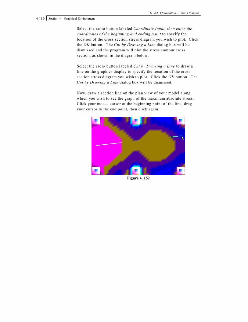
STAAD.foundation – User’s Manual
Section 4 – Graphical Environment
4-110
Select the radio button labeled Coordinate Input, then enter the coordinates of the beginning and ending point to specify the location of the cross section stress diagram you wish to plot. Click the OK button. The Cut by Drawing a Line dialog box will be dismissed and the program will plot the stress contour cross section, as shown in the diagram below. Select the radio button labeled Cut by Drawing a Line to draw a line on the graphics display to specify the location of the cross section stress diagram you wish to plot. Click the OK button. The Cut by Drawing a Line dialog box will be dismissed. Now, draw a section line on the plan view of your model along which you wish to see the graph of the maximum absolute stress. Click your mouse cursor at the beginning point of the line, drag your cursor to the end point, then click again.
Figure 4. 152

Section 4 – Graphical Environment
4-111
Now click on the button labeled View Cut Section. The following figure appears in the graphics window.
Figure 4. 153
Now click the button labeled Design Selected Line. A dialog box labeled Design Report Along a Selected Line will be displayed.
Figure 4. 154

STAAD.foundation – User’s Manual
Section 4 – Graphical Environment
4-112
Click on the Design button to calculate the required reinforcement area for each element along the cut line.
Figure 4. 155

Section 4 – Graphical Environment
4-113
4.4 The Menu Commands
This section provides a description of commands available from STAAD.foundation’s pull-down menus. The names of the pull-down menus, from left to right across the top of the screen, are:
• File • Edit • View • Tools • Select • Grid Setup • Window • Help

STAAD.foundation – User’s Manual
Section 4 – Graphical Environment
4-114
4.4.1 File Menu
Used for operations involving files. Such operations include opening, saving, importing and printing.
Figure 4. 156
Import
The Import command is used to begin a new project by importing the support geometry and support reactions from a STAAD.Pro analysis. The ability to import analysis data from other structural analysis software programs will be provided in a future release of STAAD.foundation.

Section 4 – Graphical Environment
4-115
You can only import a STAAD.Pro model which has been successfully analyzed, because you will want to have the support reactions available for the foundation design. When the Import command is selected, a file manager dialog box labeled STAADPro File Import will be displayed.
Figure 4. 157
Locate the STAAD.Pro input file you wish to import and highlight it. Click on the Open button.
Figure 4. 158
A dialog box appears listing all the available load cases in the STAAD.Pro file. You may select any or all of the load cases by toggling on the corresponding check box, then click on the Import

STAAD.foundation – User’s Manual
Section 4 – Graphical Environment
4-116
button. The dialog box will be dismissed and the program will create a new project with a default project name. The support coordinates and load cases from your STAAD.Pro analysis will be imported into STAAD.foundation.
Save Picture
This command saves the contents of the graphics window in a bitmap file.
Figure 4. 159
When the Save Picture command is selected, a file manager dialog box is displayed.
Figure 4. 160
Enter a file name and click the Save button. The file name is automatically appended with the BMP extension and the file is saved in the designated location.
Section 4 – Graphical Environment
4-117
4.4.2 Edit Menu
The Edit menu contains five commands:
• Undo • Cut • Copy • Paste • Delete
These standard windows commands are active only when a relevant item or operation has been selected.
Undo
Reverses the effect of the previous command.
Cut
Moves the selected item(s) to the clipboard.
Copy
Copies the selected item(s) to the clipboard.
Paste
Inserts the contents of the clipboard.
Delete
Deletes the selected item(s).

STAAD.foundation – User’s Manual
Section 4 – Graphical Environment
4-118
4.4.3 View Menu
The View menu contains commands that control the STAAD.foundation display. Some commands control the viewing angle and the types of objects shown in the graphics window, and allows you to customize the appearance of the objects you choose to display. You can also control the display of the tool tip help, select annotation fonts, set scales and exaggeration factors for graphs, and turn various toolbars, status bars and menus on and off.
Figure 4. 161
Change Background Color
Allows you to specify the background color of the graphics window. When you select the Change Background Color command, a color palette opens.

Section 4 – Graphical Environment
4-119
Figure 4. 162
Select the desired color and click the OK button.
Zoom
This command allows you to change your apparent distance from objects in the graphics window. Clicking on the Zoom command displays a cascading sub-menu containing three commands:
• Zoom In: move closer • Zoom Out: move farther away • Zoom All: view the entire model • Zoom Window: drag a rubber band line around the area you
wish to view
Pan
Allows you to move the frame of the graphics window up, down or sideways with respect to the model.

STAAD.foundation – User’s Manual
Section 4 – Graphical Environment
4-120
Projections
Changes the viewpoint of the graphics window with respect to the global axis system. When you select the Projections command, seven sub-commands are displayed in a cascading sub-menu:
• View from +Z • View from –Z • View from +X • View from –X • View from Top • View from Bottom • Isometric
Options
When the Options command is selected, the program displays the Set Viewing Options dialog box.
Figure 4. 163
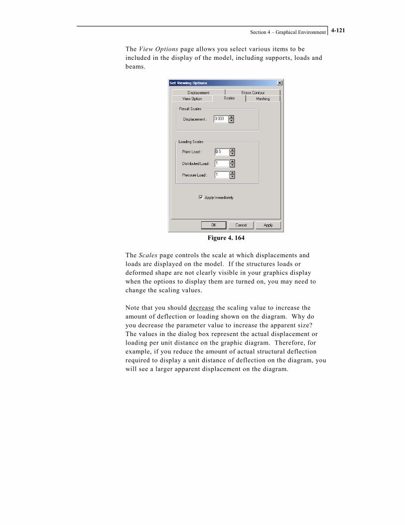
Section 4 – Graphical Environment
4-121
The View Options page allows you select various items to be included in the display of the model, including supports, loads and beams.
Figure 4. 164
The Scales page controls the scale at which displacements and loads are displayed on the model. If the structures loads or deformed shape are not clearly visible in your graphics display when the options to display them are turned on, you may need to change the scaling values. Note that you should decrease the scaling value to increase the amount of deflection or loading shown on the diagram. Why do you decrease the parameter value to increase the apparent size? The values in the dialog box represent the actual displacement or loading per unit distance on the graphic diagram. Therefore, for example, if you reduce the amount of actual structural deflection required to display a unit distance of deflection on the diagram, you will see a larger apparent displacement on the diagram.

STAAD.foundation – User’s Manual
Section 4 – Graphical Environment
4-122
Figure 4. 165
The Meshing page allows you to control the appearance of the plates and nodes of the finite element mesh used to represent a mat foundation. Clicking on the two colored boxes under the Plates and Meshed Nodes categories opens a color palette that allows you to specify the color in which these two components are to be displayed.
Figure 4. 166

Section 4 – Graphical Environment
4-123
The Displacement page allows you to control the appearance of the displacement diagram. Clicking on the two colored boxes under the Node Displacement Diagram and Beam Displacement Diagram categories opens a color palette that allows you to specify the color in which these two components are to be displayed.
Figure 4. 167
The Stress Contour page allows you to select the type of stress contour diagram you wish to display on the structure. An Apply Immediately check box appears on several of the pages in the Set Viewing Options dialog box. When the Apply Immediately check box is toggled on, changes made in the Set Viewing Options dialog box are immediately displayed in the main view, without the need to click the Apply or OK buttons. This feature allows you to see in real time the effect of adjusting the various parameters in the dialog box.
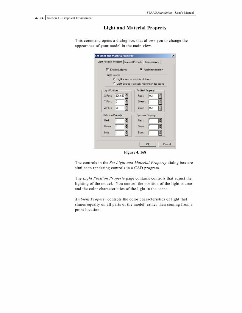
STAAD.foundation – User’s Manual
Section 4 – Graphical Environment
4-124
Light and Material Property
This command opens a dialog box that allows you to change the appearance of your model in the main view.
Figure 4. 168
The controls in the Set Light and Material Property dialog box are similar to rendering controls in a CAD program. The Light Position Property page contains controls that adjust the lighting of the model. You control the position of the light source and the color characteristics of the light in the scene. Ambient Property controls the color characteristics of light that shines equally on all parts of the model, rather than coming from a point location.
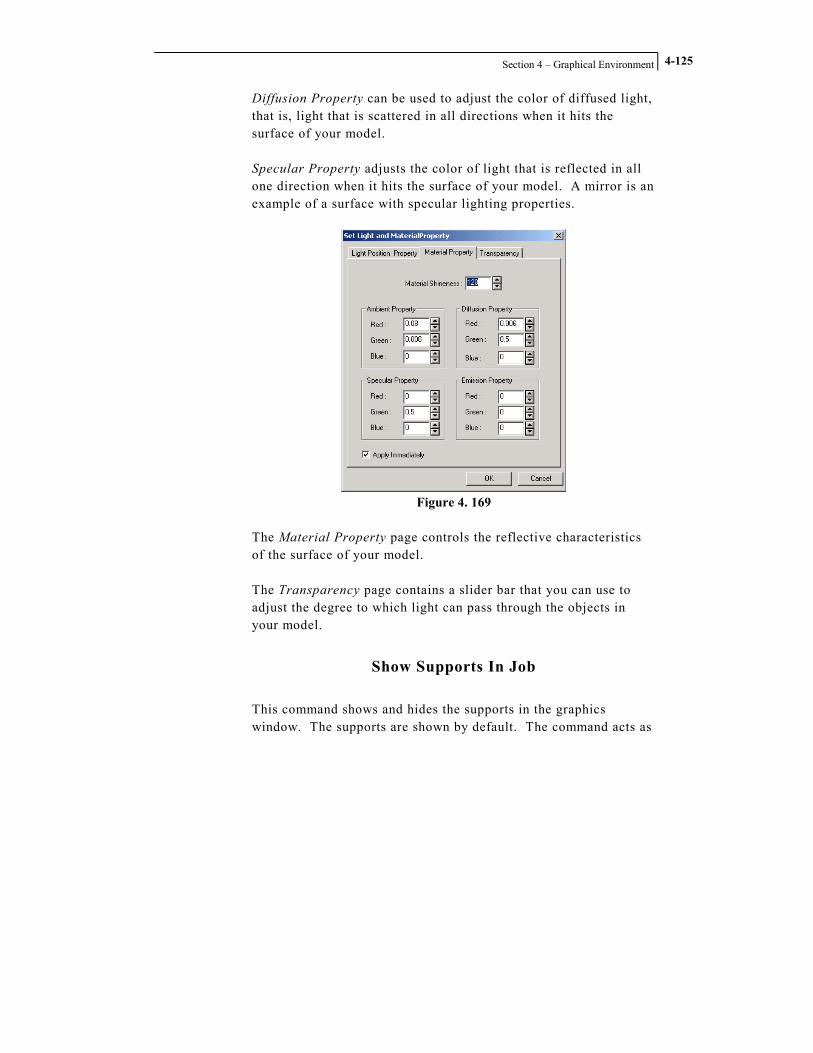
Section 4 – Graphical Environment
4-125
Diffusion Property can be used to adjust the color of diffused light, that is, light that is scattered in all directions when it hits the surface of your model. Specular Property adjusts the color of light that is reflected in all one direction when it hits the surface of your model. A mirror is an example of a surface with specular lighting properties.
Figure 4. 169
The Material Property page controls the reflective characteristics of the surface of your model. The Transparency page contains a slider bar that you can use to adjust the degree to which light can pass through the objects in your model.
Show Supports In Job
This command shows and hides the supports in the graphics window. The supports are shown by default. The command acts as
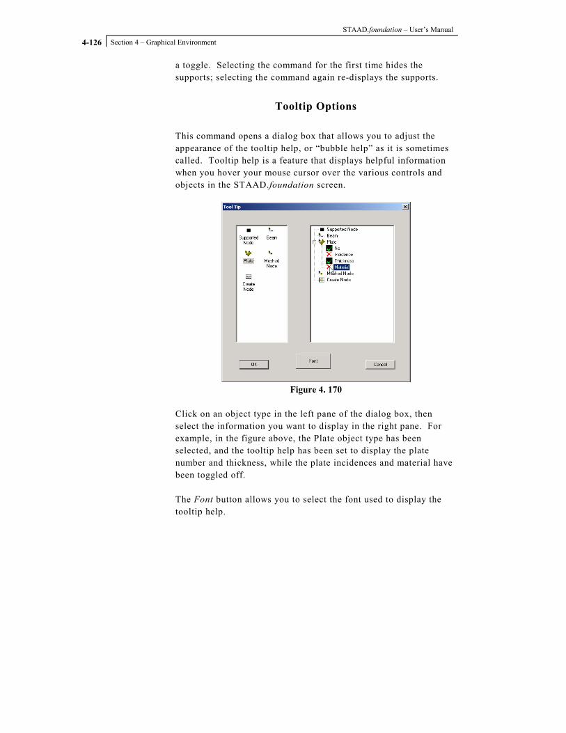
STAAD.foundation – User’s Manual
Section 4 – Graphical Environment
4-126
a toggle. Selecting the command for the first time hides the supports; selecting the command again re-displays the supports.
Tooltip Options
This command opens a dialog box that allows you to adjust the appearance of the tooltip help, or “bubble help” as it is sometimes called. Tooltip help is a feature that displays helpful information when you hover your mouse cursor over the various controls and objects in the STAAD.foundation screen.
Figure 4. 170
Click on an object type in the left pane of the dialog box, then select the information you want to display in the right pane. For example, in the figure above, the Plate object type has been selected, and the tooltip help has been set to display the plate number and thickness, while the plate incidences and material have been toggled off. The Font button allows you to select the font used to display the tooltip help.

Section 4 – Graphical Environment
4-127
Toolbar
The Toolbar command displays a dialog box that allows you to control which toolbars are present, and which toolbar buttons that appear in each toolbar.
Figure 4. 171
Status Bar
This command is a toggle that turns the Status Bar on and off. The Status Bar is at the bottom of the STAAD.foundation screen and displays a variety of helpful information, depending on which part of the program you are using, and which command is currently active. When you hover your mouse cursor over a toolbar button, the left side of the Status Bar displays an explanation on how to use the command associated with that particular button.

STAAD.foundation – User’s Manual
Section 4 – Graphical Environment
4-128
4.4.4 Tools Menu
The Tools menu contains commands for setting up drawing styles, manipulating the structure geometry, managing jobs, and setting display scales.
Figure 4. 172
Color and Dimension Setup
This command opens a dialog box that allows you to configure the appearance of the design and detail drawings created by the program. The Color and Dimension Setup dialog box contains four pages:
• Dimension Style • Color Setup • Annotation • Zone Color Setup
The dialog box opens with the Dimension Style page active.

Section 4 – Graphical Environment
4-129
Figure 4. 173
The Geometry category allows you to select the Arrow Style, Arrow Size, and the extension and offset distance for the dimension lines. You can set the dimension display units, select the colors of the dimension lines and arrows and set the font style for the dimension text.
Figure 4. 174

STAAD.foundation – User’s Manual
Section 4 – Graphical Environment
4-130
The Color Setup page allows you to access a set of color palettes you can use to set the colors for various parts of the design drawings produced by the program.
Figure 4. 175
The Annotation page allows you to specify the font style for design drawing annotation.
Figure 4. 176

Section 4 – Graphical Environment
4-131
You can use the Zone Color Setup page to specify the color used by the program to delineate the various reinforcement zones in your mat foundation design.
Translational Repeat
The Translational Repeat command is used to duplicate existing objects in your model. It is like a Copy command, except that it allows you to create multiple copies using a single command, and link those copies together with transverse members if desired. The command is inactive or “grayed out” in the menu until you select some objects in the model. To use Translational Repeat, first select the objects you wish to duplicate, then select Translational Repeat from the Tools menu. The Translational Repeat dialog box will be displayed.
Figure 4. 177
Use the No. of Steps edit box to specify the number of copies of the selected object(s) you wish to create. The Increment category is used to specify the distance from the original object(s) to the copied object(s). When No. of Steps is greater than 1, the increment values will also specify the distance between the multiple copied objects created by the program. The increment units are the units currently selected in the Units drop-down menu, which is located in the Tools toolbar.

STAAD.foundation – User’s Manual
Section 4 – Graphical Environment
4-132
Figure 4. 178
Toggle the Link Steps check box on if you also want the program to link the copied objects with transverse members.
Add New Job
When you begin a new project, only the Project Info, Foundation Plan and Loads and Factors page tabs will appear in the Page Control. These three tabs allow you to specify the physical model upon which the foundation design is to be performed. It is only when you specify a Job (a set of constraints for the program to use in performing a foundation design) that Page Control tabs related to the design process will appear. Selecting the Add New Job command from the Tools menu opens a dialog box which you can use to create a new design job within your project.
Figure 4. 179
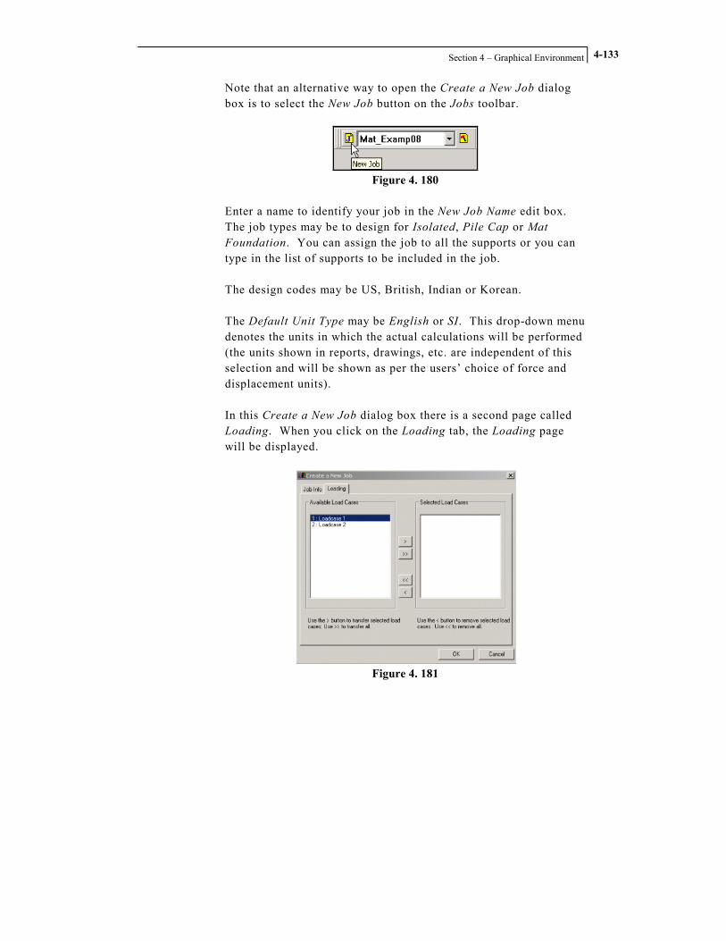
Section 4 – Graphical Environment
4-133
Note that an alternative way to open the Create a New Job dialog box is to select the New Job button on the Jobs toolbar.
Figure 4. 180
Enter a name to identify your job in the New Job Name edit box. The job types may be to design for Isolated, Pile Cap or Mat Foundation. You can assign the job to all the supports or you can type in the list of supports to be included in the job. The design codes may be US, British, Indian or Korean. The Default Unit Type may be English or SI. This drop-down menu denotes the units in which the actual calculations will be performed (the units shown in reports, drawings, etc. are independent of this selection and will be shown as per the users’ choice of force and displacement units). In this Create a New Job dialog box there is a second page called Loading. When you click on the Loading tab, the Loading page will be displayed.
Figure 4. 181
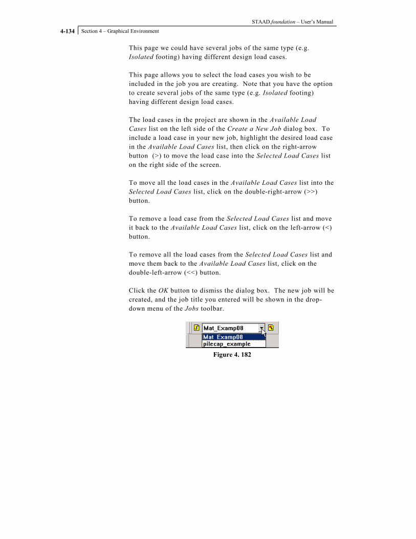
STAAD.foundation – User’s Manual
Section 4 – Graphical Environment
4-134
This page we could have several jobs of the same type (e.g. Isolated footing) having different design load cases. This page allows you to select the load cases you wish to be included in the job you are creating. Note that you have the option to create several jobs of the same type (e.g. Isolated footing) having different design load cases. The load cases in the project are shown in the Available Load Cases list on the left side of the Create a New Job dialog box. To include a load case in your new job, highlight the desired load case in the Available Load Cases list, then click on the right-arrow button (>) to move the load case into the Selected Load Cases list on the right side of the screen. To move all the load cases in the Available Load Cases list into the Selected Load Cases list, click on the double-right-arrow (>>) button. To remove a load case from the Selected Load Cases list and move it back to the Available Load Cases list, click on the left-arrow (<) button. To remove all the load cases from the Selected Load Cases list and move them back to the Available Load Cases list, click on the double-left-arrow (<<) button. Click the OK button to dismiss the dialog box. The new job will be created, and the job title you entered will be shown in the drop-down menu of the Jobs toolbar.
Figure 4. 182

Section 4 – Graphical Environment
4-135
Edit Current Job
This command allows you to make changes to an existing job. You can change the loads, change the job name, change the supports in the job, etc. To make changes to an existing job, first make sure that the job you want to modify is the currently active job. When the Edit Current Job command is selected, the following dialog box appears.
Figure 4. 183
Note that an alternative way to open the Edit Existing Job dialog box is to select the Edit Current Job button on the Jobs toolbar.
Figure 4. 184

STAAD.foundation – User’s Manual
Section 4 – Graphical Environment
4-136
The controls in this dialog box are identical to those in the New Job dialog box. Please see the description of the New Job dialog box for an explanation of the options in the Edit Existing Job dialog box. When you modify the job parameters and click the OK button, a warning message will be displayed:
Figure 4. 185
Since you are changing the job parameters, previous analysis and design results for the job are invalid. To protect the integrity of the results displayed by the program, STAAD.foundation deletes analysis and design results when you make changes to the parameters that govern the outcome of those analysis and design results. Click the Yes button to modify the job parameters, delete the existing results files, and dismiss the Edit Existing Job dialog box. Clicking the No button will return you to the Edit Existing Job dialog box, where you can either continue to modify the job parameters, or click the Cancel button to dismiss the Edit Existing Job dialog box without making any changes.
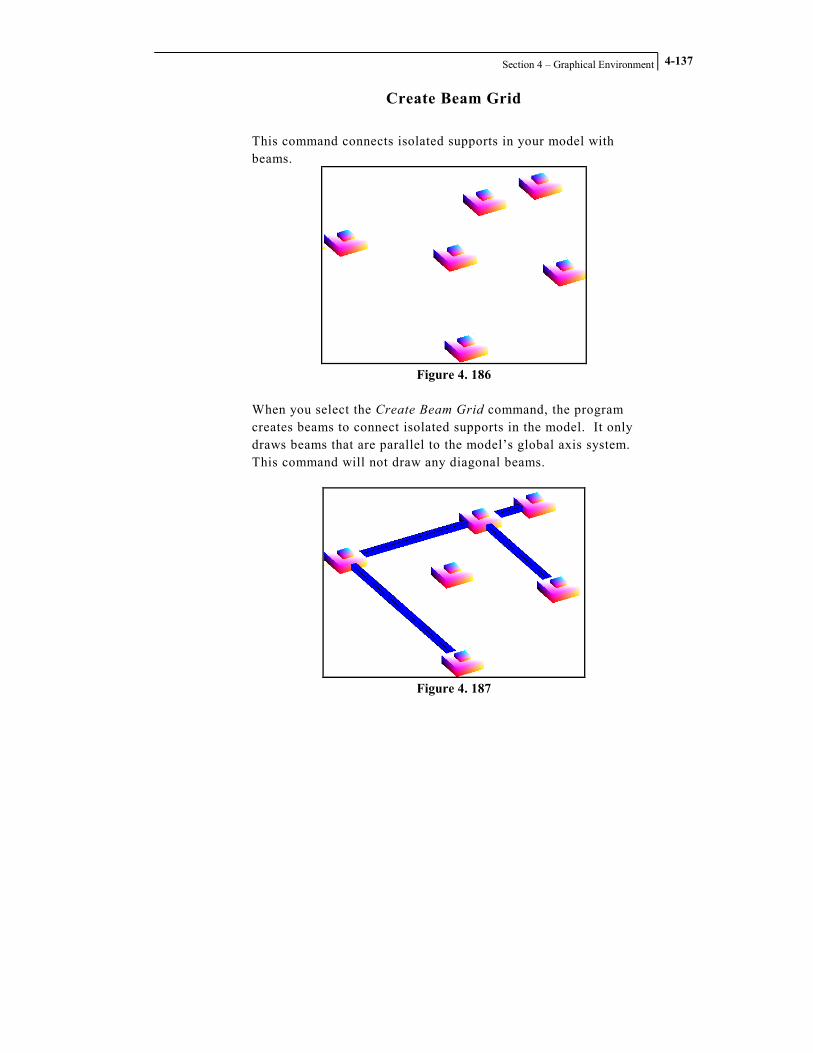
Section 4 – Graphical Environment
4-137
Create Beam Grid
This command connects isolated supports in your model with beams.
Figure 4. 186
When you select the Create Beam Grid command, the program creates beams to connect isolated supports in the model. It only draws beams that are parallel to the model’s global axis system. This command will not draw any diagonal beams.
Figure 4. 187

STAAD.foundation – User’s Manual
Section 4 – Graphical Environment
4-138
Scales
This command allows you to change the size of load symbols and the apparent displacement of your structure due to the applied loading. When you select the Scales command, the Set Viewing Options dialog box opens with the Scales page active.
Figure 4. 188
You may adjust the apparent magnitude of the Results and Loading Scales on your diagram. Note that you should decrease the Displacement value to increase the amount of deflection shown. Why do you decrease it to increase the deflection? The Displacement value in the dialog box is the actual displacement of the structure per unit distance on the structure diagram. Therefore, if you reduce the amount of actual structural deflection required to display a unit distance of deflection on the diagram, you will see a larger apparent displacement on the diagram.

Section 4 – Graphical Environment
4-139
4.4.5 Select Menu
The Select menu contains commands that allow you to select objects in your model using a wide variety of methods.
Figure 4. 189
Familiarizing yourself with the commands in the Select menu will enable you to work more efficiently, because you will know how to quickly select only the desired objects, rather than having to select them one at a time. STAAD.foundation offers a set of specialized cursors. Activating one of these cursors allows you to use your mouse to select only a certain kind of object. For example, activating the Support Node Cursor makes it easy to select a support node that is surrounded by an array of grid nodes. STAAD.foundation also offers a variety of selection methods based on the object type, its orientation with respect to the axis system, its identification number, etc.

STAAD.foundation – User’s Manual
Section 4 – Graphical Environment
4-140
Support Node Cursor
This command toggles the Support Node Cursor on and off. When the Support Node Cursor is active, clicking with the mouse will select only support nodes and will ignore all other types of objects. A check mark next to the menu command indicates that the Support Node Cursor is active. Selecting the command again or activating one of the other cursors deactivates the cursor.
Mesh Node Cursor
This command toggles the Mesh Node Cursor on and off. When the Mesh Node Cursor is active, clicking with the mouse will select only mesh nodes and will ignore all other types of objects. A check mark next to the menu command indicates that the Mesh Node Cursor is active. Selecting the command again or activating one of the other cursors deactivates the cursor. The Mesh Node Cursor can also be toggled on and off by clicking on the Select Meshed Nodes Cursor toolbar button.
Figure 4. 190
Physical Beam Cursor
This command toggles the Physical Beam Cursor on and off. When the Physical Beam Cursor is active, clicking with the mouse will select only beams and will ignore all other types of objects. A check mark next to the menu command indicates that the Physical Beam Cursor is active. Selecting the command again or activating one of the other cursors deactivates the cursor.

Section 4 – Graphical Environment
4-141
The Physical Beam Cursor can also be toggled on and off by clicking on the Select Physical Member Cursor toolbar button.
Figure 4. 191
Plate Cursor
This command toggles the Plate Cursor on and off. When the Plate Cursor is active, clicking with the mouse will select only plates and will ignore all other types of objects. A check mark next to the menu command indicates that the Plate Cursor is active. Selecting the command again or activating one of the other cursors deactivates the cursor. The Plate Cursor can also be toggled on and off by clicking on the Select Plates Cursor toolbar button.
Figure 4. 192
Beams Parallel To
Selects all beams in the model that are parallel to one of the global axes. When you select the Beams Parallel To command, a cascading sub-menu appears.
Figure 4. 193
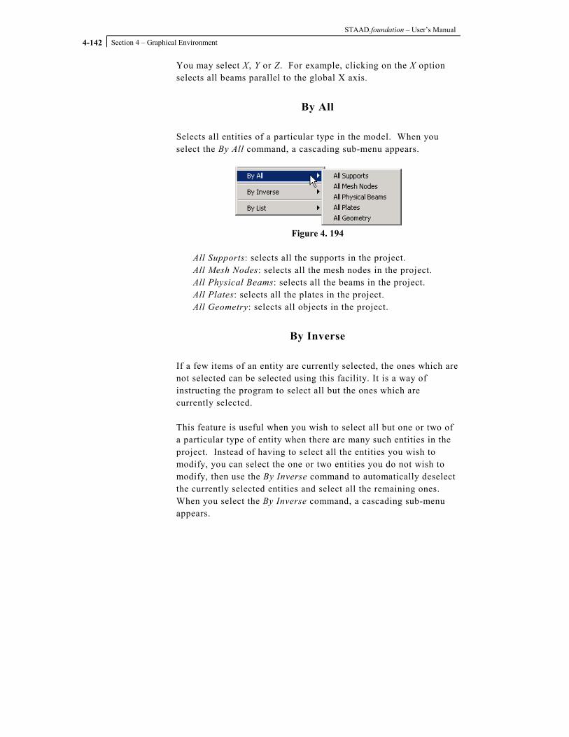
STAAD.foundation – User’s Manual
Section 4 – Graphical Environment
4-142
You may select X, Y or Z. For example, clicking on the X option selects all beams parallel to the global X axis.
By All
Selects all entities of a particular type in the model. When you select the By All command, a cascading sub-menu appears.
Figure 4. 194
All Supports: selects all the supports in the project. All Mesh Nodes: selects all the mesh nodes in the project. All Physical Beams: selects all the beams in the project. All Plates: selects all the plates in the project. All Geometry: selects all objects in the project.
By Inverse
If a few items of an entity are currently selected, the ones which are not selected can be selected using this facility. It is a way of instructing the program to select all but the ones which are currently selected. This feature is useful when you wish to select all but one or two of a particular type of entity when there are many such entities in the project. Instead of having to select all the entities you wish to modify, you can select the one or two entities you do not wish to modify, then use the By Inverse command to automatically deselect the currently selected entities and select all the remaining ones. When you select the By Inverse command, a cascading sub-menu appears.

Section 4 – Graphical Environment
4-143
Figure 4. 195
Inverse Support Selection: deselects the currently selected
supports and selects all the remaining ones
Inverse Mesh Node Selection: deselects the currently selected mesh nodes and selects all the remaining ones
Inverse Physical Beam Selection: deselects the currently selected beams and selects all the remaining ones
Inverse Plate Selection: deselects the currently selected plates and selects all the remaining ones
By List
The By List option is used to select a few desired objects from a list of all objects of that type present in the model. When you select the By List command, a cascading sub-menu appears.
Figure 4. 196

STAAD.foundation – User’s Manual
Section 4 – Graphical Environment
4-144
If you click on the Support Nodes command in the sub-menu, a Select Nodes dialog box is displayed.
Figure 4. 197
This dialog box provides two different ways for selecting the support nodes. You can click on the node numbers in the list box of the node(s) you wish to select. Clicking on an item in the list highlights it. Clicking on it a second time un-highlights it. You can highlight as many items in the list as you wish. Alternatively, you can type the node numbers of the support node(s) you wish to select in the Enter List edit box. Click the Close button to dismiss the dialog box. You can select Mesh Nodes, Physical Beams and Plates in the same way.
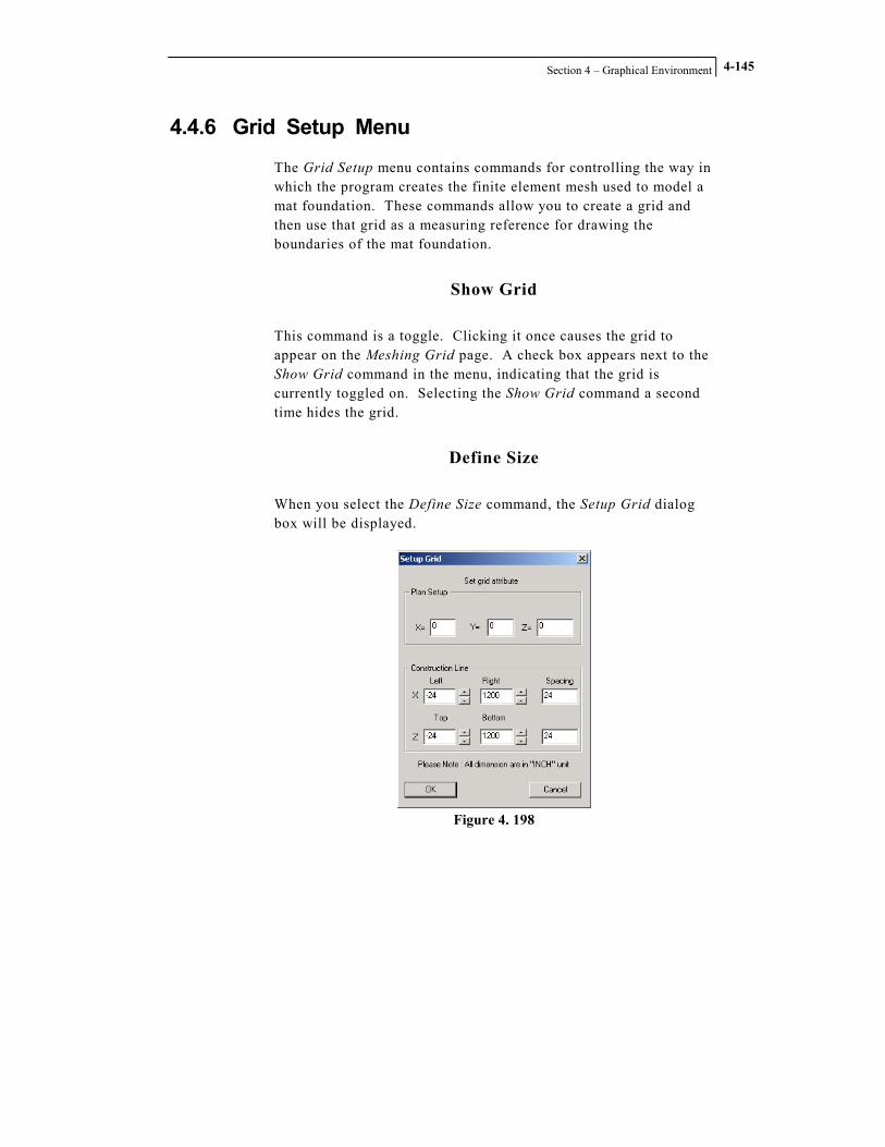
Section 4 – Graphical Environment
4-145
4.4.6 Grid Setup Menu
The Grid Setup menu contains commands for controlling the way in which the program creates the finite element mesh used to model a mat foundation. These commands allow you to create a grid and then use that grid as a measuring reference for drawing the boundaries of the mat foundation.
Show Grid
This command is a toggle. Clicking it once causes the grid to appear on the Meshing Grid page. A check box appears next to the Show Grid command in the menu, indicating that the grid is currently toggled on. Selecting the Show Grid command a second time hides the grid.
Define Size
When you select the Define Size command, the Setup Grid dialog box will be displayed.
Figure 4. 198

STAAD.foundation – User’s Manual
Section 4 – Graphical Environment
4-146
The values shown in the Setup Grid dialog box are in units of inches. You may use this dialog box to adjust the size, grid line spacing, and location of the origin of your meshing grid.
The Plan Setup category allows you to specify which plane you want to work in, and where you want the origin of the grid to be, relative to the global coordinate system of your model. The Construction Line category allows you to specify the distance you wish the grid to extend on either side of the grid origin, and the spacing between grid lines.
Polygonal Boundary
Figure 4. 199

Section 4 – Graphical Environment
4-147
Figure 4. 200
Circular Boundary
Add Node
Zoom In
Makes the scale of the grid display larger so that you appear to move closer to the grid so that you can see the grid objects in the data area in greater detail (there is also a Zoom In command in the View menu and a Zoom In tool in the Zoom toolbar, but the commands in the View menu and the tools on the Zoom toolbar are used to alter the view in the graphics window rather than in the Meshing Grid page of the Page Control).

STAAD.foundation – User’s Manual
Section 4 – Graphical Environment
4-148
Zoom Out
Makes the scale of the grid display smaller so that you appear to move higher above the grid so that you can see more of it (there is also a Zoom Out command in the View menu and a Zoom Out tool in the Zoom toolbar, but the commands in the View menu and the tools on the Zoom toolbar are used to alter the view in the graphics window rather than in the Meshing Grid page of the Page Control).
Transfer to Job
The Transfer to Job command is used to transfer boundaries that you have drawn on the grid into the main view of your model.
Figure 4. 201
Figure 4. 202
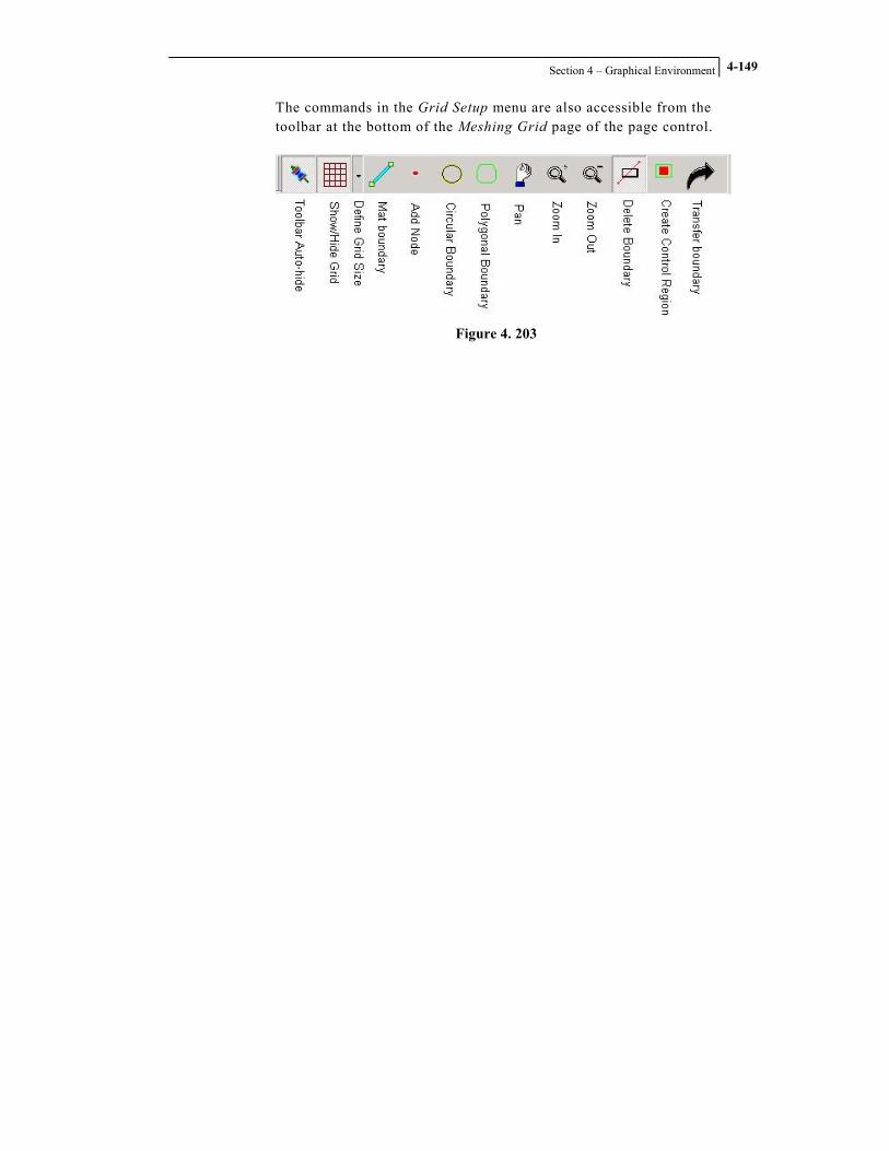
Section 4 – Graphical Environment
4-149
The commands in the Grid Setup menu are also accessible from the toolbar at the bottom of the Meshing Grid page of the page control.
Figure 4. 203

STAAD.foundation – User’s Manual
Section 4 – Graphical Environment
4-150
4.4.7 Window Menu
Figure 4. 204
The Window menu contains commands used to switch between various window options such as cascade, tile horizontal, and tile vertical. In addition, any project window currently open can be selected from the Window menu to make it the active window. The menu commands under Window are useful when you have multiple projects open at a time. For example, the Tile Vertical command allows you to view multiple projects side-by-side.

Section 4 – Graphical Environment
4-151
Cascade
Cascade places the open windows in a diagonal order starting from the upper left-hand portion of the screen and ending at the lower right-hand portion of the screen.
Figure 4. 205

STAAD.foundation – User’s Manual
Section 4 – Graphical Environment
4-152
Tile Horizontal
Tile Horizontal places the open windows so that each one runs across the screen from left to right, with each window placed one above the other.
Figure 4. 206

Section 4 – Graphical Environment
4-153
Tile Vertical Tile Vertical places the open windows so that each one runs across the screen from top to bottom, with each window placed side by side.
Figure 4. 207
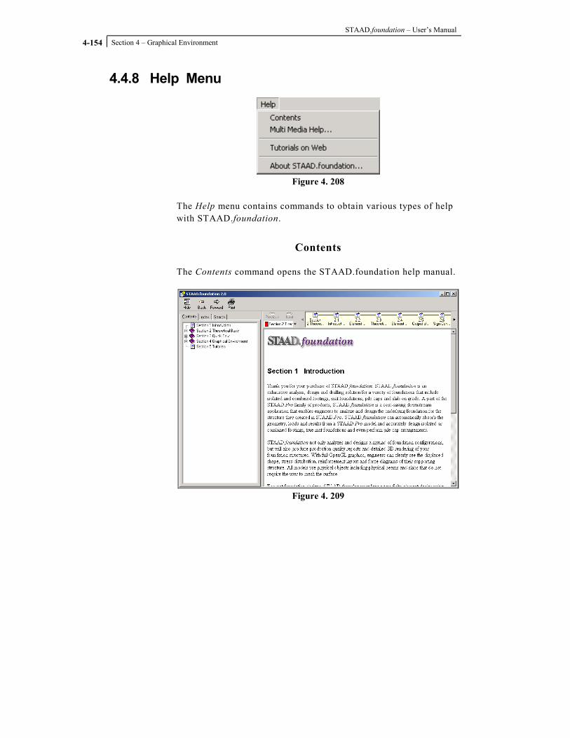
STAAD.foundation – User’s Manual
Section 4 – Graphical Environment
4-154
4.4.8 Help Menu
Figure 4. 208
The Help menu contains commands to obtain various types of help with STAAD.foundation.
Contents
The Contents command opens the STAAD.foundation help manual.
Figure 4. 209

Section 4 – Graphical Environment
4-155
Multi Media Help
The Multi Media Help command opens a window allowing you to select from several different movie tutorials in Viewlet format. Each movie tutorial guides you through a different aspect of STAAD.foundation. The movie tutorials are great way to see STAAD.foundation being used in action.
Figure 4. 210

STAAD.foundation – User’s Manual
Section 4 – Graphical Environment
4-156
Tutorials on Web
The Tutorials on Web command opens an Internet browser window to the tutorials page on www.reiworld.com. The tutorials page offers various types of tutorials for all the products offered by Research Engineers International. This command allows you to view the latest tutorials offered.
Figure 4. 211

Section 4 – Graphical Environment
4-157
About STAAD.foundation
The About STAAD.foundation option brings up a dialog box containing information about the version of STAAD.foundation that is being used. The information in the dialog box includes product name, release number and build number. In addition, the physical address, web address and phone numbers for the Research Engineers International Headquarters is displayed.
Figure 4. 212
To obtain information about other locations, click on the Support button. A new dialog box will appear with a map of the world. Hover your mouse cursor over the location, designated by small dots, which you would like to obtain information on. The information for that location will be displayed in the lower left-hand corner of the dialog box.

STAAD.foundation – User’s Manual
Section 4 – Graphical Environment
4-158
Figure 4. 213

Section 4 – Graphical Environment
4-159
4.5 The Toolbars
Figure 4. 214
STAAD.foundation offers a set of "dockable" and "floating" toolbars for quick access to frequently used commands. By default, the toolbar icons appear at the top of the STAAD.foundation screen immediately below the menu bar. You may, however, drag each toolbar and place it at any position on screen (hence the term "floating"). In addition, if you drag a floating toolbar close to the menu bar, the toolbar gets embedded in the area below the menu bar (hence the term "dockable"). The title of a "docked" toolbar is not displayed. However, if you drag the toolbar and leave it "floating" on the screen, the toolbar displays a title at the top. Each toolbar icon offers tooltip help. If you are not sure what a toolbar icon does, place your mouse cursor over the toolbar icon for a moment and a floating help message appears to identify what the toolbar icon does. STAAD.foundation offers several toolbars, each of which contains several toolbar icons. The toolbars are described in following subsections.

STAAD.foundation – User’s Manual
Section 4 – Graphical Environment
4-160
4.5.1 File Toolbar The File Toolbar allows you to perform file related operations and contains three icons as shown in Figure X; New, Open, and Save.
Figure 4. 215
New Icon
The New icon creates a new STAAD.foundation project.
Open Icon
The Open icon brings up the open file dialog box and allows you to open an existing STAAD.foundation project.
Figure 4. 216

Section 4 – Graphical Environment
4-161
Save Icon
The Save icon brings up the save file dialog box the first time the icon is clicked and allows you to save the current project to a file. After a project has been saved to a file, clicking the Save icon will simply save any updates made to the project to the file you specified earlier.
Figure 4. 217
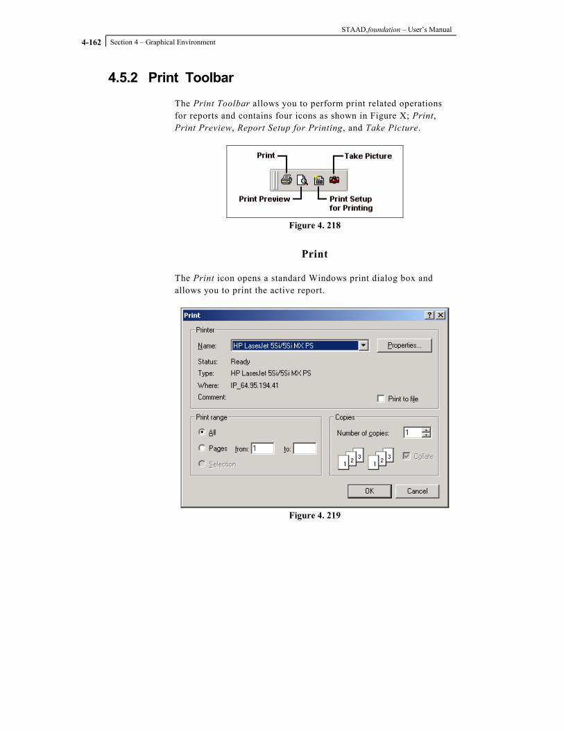
STAAD.foundation – User’s Manual
Section 4 – Graphical Environment
4-162
4.5.2 Print Toolbar The Print Toolbar allows you to perform print related operations for reports and contains four icons as shown in Figure X; Print, Print Preview, Report Setup for Printing, and Take Picture.
Figure 4. 218
The Print icon opens a standard Windows print dialog box and allows you to print the active report.
Figure 4. 219

Section 4 – Graphical Environment
4-163
Print Preview
The Print Preview icon opens a new window allowing you to view what the active report will look like when printed out.
Figure 4. 220
Report Setup for Printing
The Report Setup for Print icon opens a dialog box allowing you to select what items will appear in the active report.
Figure 4. 221

STAAD.foundation – User’s Manual
Section 4 – Graphical Environment
4-164
Take Picture
The Take Picture icon takes a snapshot of the main view pane. Pictures taken will then be selectable items when creating reports via the Report Setup for Print dialog box. Pictures are grouped together with the job they are created in.

Section 4 – Graphical Environment
4-165
4.5.3 Jobs Toolbar The Jobs Toolbar allows you to create, select, and edit jobs. The Jobs Toolbar contains two icons and a drop-down list box as shown in Figure X; New Job, Edit Current Job and Change Job. Jobs allow you to assign a set of constraints for STAAD.foundation to use in performing a foundation design.
Figure 4. 222
New Job
The New Job icon opens a dialog box allowing you to create a new job.
Figure 4. 223

STAAD.foundation – User’s Manual
Section 4 – Graphical Environment
4-166
Change Job
The Change Job drop-down list box allows you to select a job from a list of jobs you have created.
Figure 4. 224
Edit Current Job
The Edit Current Job icon opens a dialog box allowing you to edit information pertaining to the currently select job, such as job name, job type, design code, default unit type, supports and loads.
Figure 4. 225

Section 4 – Graphical Environment
4-167
4.5.4 Help Toolbar The Help Toolbar allows you to obtain information about STAAD.foundation and contains one icon; About.
Figure 4. 226
About
The About icon opens a dialog box containing information on the version of STAAD.foundation you’re currently running.

STAAD.foundation – User’s Manual
Section 4 – Graphical Environment
4-168
4.5.5 Edit Toolbar The Edit Toolbar allows you to perform cut, copy, and paste operations.
Figure 4. 227
---

Section 4 – Graphical Environment
4-169
4.5.6 Rotate Toolbar The Rotate Toolbar allows you to
Figure 4. 228
asdf

STAAD.foundation – User’s Manual
Section 4 – Graphical Environment
4-170
4.5.7 Zoom Toolbar The Zoom Toolbar allows you to
Figure 4. 229
adsf

Section 4 – Graphical Environment
4-171
4.5.8 Loading Toolbar The Loading Toolbar allows you to
Figure 4. 230
asdf

STAAD.foundation – User’s Manual
Section 4 – Graphical Environment
4-172
4.5.9 Tools Toolbar The Tools Toolbar allows you to
Figure 4. 231
asdf

Section 4 – Graphical Environment
4-173
4.5.10 Geometry Toolbar The Geometry Toolbar allows you to
Figure 4. 232
adsf

STAAD.foundation – User’s Manual
Section 4 – Graphical Environment
4-174