
ST730 User Manual - Cloudinary
47
ST730 – User Manual V20 1/47 08/Jan/2018 ST730 – User Manual
Transcript of ST730 User Manual - Cloudinary

ST730 – User Manual
V20
1/47 08/Jan/2018
ST730 – User Manual
ST730 – User Manual
V20
2/47 08/Jan/2018
1 History Log ................................................................................................................................ 6
2 Overview ................................................................................................................................... 7
3 User Interface ........................................................................................................................... 7
4 Features .................................................................................................................................... 8
4.1 Tracking ........................................................................................................................... 8
4.2 Virtual ignition .................................................................................................................. 8
4.3 Temperature monitoring .................................................................................................. 9
4.4 Maximum number of messages per day ......................................................................... 9
4.5 Fences ........................................................................................................................... 10
4.6 GPS configuration ......................................................................................................... 10
4.7 Events ........................................................................................................................... 11
4.7.1 Power On/Off ......................................................................................................... 11
4.7.2 SOS ....................................................................................................................... 11
4.7.3 Hall sensor ............................................................................................................ 11
4.7.4 Battery change ...................................................................................................... 11
4.7.5 Movement .............................................................................................................. 11
4.7.6 Jamming ................................................................................................................ 11
4.7.7 Fences ................................................................................................................... 12
4.7.8 Low battery ............................................................................................................ 12
4.7.9 Virtual ignition ........................................................................................................ 12
4.7.10 Temperature .......................................................................................................... 12
5 Sigfox Protocol ........................................................................................................................ 12
5.1 Data types ..................................................................................................................... 12
5.1.1 GPS location (0x01) .............................................................................................. 13
5.1.2 GPS high resolution location (0x02) ...................................................................... 13
5.1.3 Temperature (0x03) ............................................................................................... 14
5.1.4 Battery voltage (0x04) ........................................................................................... 14
5.1.5 Battery level (0x05) ............................................................................................... 14
5.1.6 Wifi MAC address (0x06) ...................................................................................... 14
5.1.7 Wifi Extended (0x07) ............................................................................................. 14
5.1.8 Accelerometer (0x08) ............................................................................................ 15
5.1.9 Speed (0x09) ......................................................................................................... 15
5.1.10 Fence number (0x8X)............................................................................................ 15
5.2 Message types .............................................................................................................. 15
5.2.1 Tracking (0x20)...................................................................................................... 17
5.2.2 Tracking with ignition on (0x21) ............................................................................. 17
5.2.3 Status Response (0x30) ........................................................................................ 17
ST730 – User Manual
V20
3/47 08/Jan/2018
5.2.4 Error (0x31) ........................................................................................................... 17
5.2.5 Tracking configuration response (0x32) ................................................................ 17
5.2.6 Event configuration response (0x33) .................................................................... 18
5.2.7 GPS configuration response (0x34) ...................................................................... 19
5.2.8 Download configuration response (0x35).............................................................. 19
5.2.9 Fence configuration response (0x36) .................................................................... 20
5.2.10 Fence Status response (0x37) .............................................................................. 20
5.2.11 Tracking ignition on configuration response (0x38) .............................................. 21
5.2.12 Power Key configuration response (0x39) ............................................................ 22
5.2.13 Temperature monitor configuration response (0x3A) ............................................ 22
5.2.14 Get Message (0x40) .............................................................................................. 23
5.2.15 Split Messages NACK (0x41) ................................................................................ 23
5.3 Sigfox commands .......................................................................................................... 23
5.3.1 Command Request (0x01) .................................................................................... 24
5.3.2 Tracking Configuration (0x02) ............................................................................... 24
5.3.3 Event Configuration (0x03) ................................................................................... 25
5.3.4 GPS Configuration (0x04) ..................................................................................... 25
5.3.5 Download Configuration (0x05) ............................................................................. 26
5.3.6 Fence Status Configuration (0x06) ....................................................................... 26
5.3.7 Sigfox Max. tracking messages per day configuration (0x07) .............................. 27
5.3.8 Split message (0x08)............................................................................................. 27
5.3.9 Fence Configuration (0x09) ................................................................................... 28
5.3.10 Virtual Ignition Enabling (0x0A) ............................................................................. 29
5.3.11 Virtual ignition Parameters Configuration (0x0B) .................................................. 29
5.3.12 Temperature Monitor Configuration (0x0C) ........................................................... 30
5.3.13 Power key Configuration (0x0D) ........................................................................... 30
6 USB Protocol .......................................................................................................................... 30
6.1 Available commands ..................................................................................................... 30
6.2 Commands detail .......................................................................................................... 31
6.2.1 AT .......................................................................................................................... 31
6.2.2 AT^ST730TCK ....................................................................................................... 31
6.2.3 AT^ST730EVT ....................................................................................................... 32
6.2.4 AT^ST730GPS ...................................................................................................... 32
6.2.5 AT^ST730DWL ...................................................................................................... 33
6.2.6 AT^ST730FNC ...................................................................................................... 34
6.2.7 AT^ST730PKT ....................................................................................................... 34
6.2.8 AT^ST730VIGN ..................................................................................................... 35
6.2.9 AT^ST730TEMPMON ........................................................................................... 36

ST730 – User Manual
V20
4/47 08/Jan/2018
6.2.10 AT^ST730CMD;;02;StatusReq .............................................................................. 36
6.2.11 AT^ST730CMD;;02;ReqSigfoxID .......................................................................... 36
6.2.12 AT^ST730CMD;;02;ReqSigfoxPAC ....................................................................... 36
6.2.13 AT^ST730CMD;;02;ReqSigfoxRCZ ...................................................................... 37
6.2.14 AT^ST730CMD;;02;ReqFwUpdate ....................................................................... 37
6.2.15 AT^ST730CMD;;02;ReqReset .............................................................................. 37
6.2.16 AT^ST730CMD;;02;ReqReboot ............................................................................ 37
6.2.17 AT^ST730CMD;;02;ReqTCK ................................................................................. 37
6.2.18 AT^ST730CMD;;02;ReqEVT ................................................................................. 37
6.2.19 AT^ST730CMD;;02;ReqDWL ................................................................................ 38
6.2.20 AT^ST730CMD;;02;ReqGPS ................................................................................ 38
6.2.21 AT^ST730CMD;;02;ReqSigfoxPacket ................................................................... 38
6.2.22 AT^ST730CMD;;02;ReqPKey ............................................................................... 38
6.2.23 AT^ST730CMD;;02;SetCustomerKey ................................................................... 39
6.2.24 AT^ST730CMD;;02;ReqVign ................................................................................. 39
6.2.25 AT^ST730CMD;;02;ReqTempMon ........................................................................ 39
6.2.26 AT^ST730CMD;;02;ReqBootloader ...................................................................... 39
6.2.27 AT^ST730CMD;;02;SetPwrKey ............................................................................. 39
6.2.28 AT^ST730CMD;;02;ReqPwrKey ........................................................................... 40
6.2.29 AT^ST730CMD;;02;ReqFNC ................................................................................ 40
7 Firmware update ..................................................................................................................... 41
8 Manufacturing commands ...................................................................................................... 41
8.1 Commands .................................................................................................................... 41
8.1.1 AT^$PSTVer .......................................................................................................... 42
8.1.2 AT^$ReadBarcode ................................................................................................ 42
8.1.3 AT^$StartFM .......................................................................................................... 42
8.1.4 AT^SIGCMD;;02;ReqSigfoxID ............................................................................... 42
8.1.5 AT^SIGCMD;;02;ReqSigfoxPAC ........................................................................... 42
8.1.6 AT^SIGCMD;;02;ReqSigfoxRCZ ........................................................................... 43
8.1.7 AT^SIGCMD;;02;ReqSigfoxID;;ReqSigfoxPAC ..................................................... 43
8.1.8 AT^$FT_ReqFTOpt ............................................................................................... 43
8.1.9 AT^$FT_BATTADC_START .................................................................................. 43
8.1.10 AT^$FT_DC_DETECT_START ............................................................................. 43
8.1.11 AT^$FT_PWRKEY_START ................................................................................... 44
8.1.12 AT^$FT_SOSKEY_START .................................................................................... 44
8.1.13 AT^$FT_HALL_IC_START .................................................................................... 44
8.1.14 AT^$FT_TEMPER_START ................................................................................... 44
8.1.15 AT^$FT_MOTION_START .................................................................................... 44
ST730 – User Manual
V20
5/47 08/Jan/2018
8.1.16 AT^$FT_GPS_START ........................................................................................... 45
8.1.17 AT^$FT_TX_START .............................................................................................. 45
8.1.18 AT^$FT_SIGFOX_END ......................................................................................... 45
8.1.19 AT^$FT_WIFI_START ........................................................................................... 45
8.1.20 AT^$ESN_WRITE ................................................................................................. 45
8.1.21 AT^$ESN_READ ................................................................................................... 46
8.1.22 AT$RADIO_PWR .................................................................................................. 46
8.1.23 AT$RADIO ............................................................................................................. 46
8.1.24 AT$WIFI_PWR ...................................................................................................... 46
8.1.25 AT$WIFI................................................................................................................. 46
8.1.26 AT^$FRCSLP ........................................................................................................ 46
8.1.27 AT^ST730CMD;;02;ReqADC ................................................................................ 47
8.1.28 AT^ST730CMD;;02;ReqWifiUpdate ...................................................................... 47
8.1.29 AT^ST730CMD;;02;ReqIO .................................................................................... 47
8.2 Validation key, Password key and Reset Key calculation ............................................. 47
ST730 – User Manual
V20
6/47 08/Jan/2018
1 History Log
Rev Date Description Author
01 May 21, 2017 First version Helder Cochofel
02 Jun 08,2017 Added new command Helder Cochofel
03 Jun 18, 2017 Fixed Event message example. Changed the sensor numbering
Helder Cochofel
04 Jun 26, 2017 Add GPS parameter limits, add new command messages, change GPS message to add the wifi backup option
Helder Cochofel
07 July 20,2017 Added Sigfox download support, added Jammer event Helder Cochofel
08 July 24th, 2017 Added GPS and Wifi fences Helder Cochofel
09 Aug 08th, 2017 Added factory interface, command to read the Sigfox
zone, complemented messages with examples Helder Cochofel
10 Aug 11th, 2017 Add message to check Sigfox zone,
Add message examples Helder Cochofel
11 Aug 15th, 2017 Add data type for the fence number.
Changed factory tests. Helder Cochofel
12 Aug 30th, 2017 Changed command to set serial number.
Fixed factory mode requirements for ReqFwUpdate and ReqWifiUpdate
Helder Cochofel
13 Sep 04th
2017 Factory test: separated the button test into 2 separate tests. Added messages to get the Sigfox ID and Zone.
Helder Cochofel
14 Sep 06th 2017 Added “AT^$FT_SIGFOX_END” message Helder Cochofel
15 Sep 08th 2017 Removed “0b” indication of a binary message Helder Cochofel
16 Sep 18th 2017 Changed accelerometer event to movement event Helder Cochofel
17 Nov 22nd
2017 Changed the layout of document. Added samples to every USB protocol message Added description to every Sigfox protocol message Added Virtual ignition and temperature monitor feature description
Helder Cochofel Gustavo Gonzalez
18 Nov 29th, 2017 Included messages examples.
Change in the features description to make them more clear
Helder Cochofel Gustavo Gonzalez
19 Dec 8th 2017 Added double wifi option to the GPS configurations
Added tables to better explain the commands parameters and limits
Helder Cochofel Gustavo Gonzalez
ST730 – User Manual
V20
7/47 08/Jan/2018
2 Overview
This document describes the features of the ST730 – Sigfox portable tracker. It will also describe the
protocol details and the possible configurations for this product.
One of the differences of this product is that it use the Sigfox network for communications.
Sigfox is a LPWAN network that operates in several countries.
So before starting using this product make sure that your product was correctly registered at Sigfox.
3 User Interface
The product has 3 LEDs, 2 external push buttons and a micro-USB connector.
The LEDs are:
Battery charge – This LED turns RED while the product is charging the battery. In addition, it
will turn GREEN while the device it transmitting to the Sigfox network.
MCU – this LED will flash with a code that relates to battery level. In addition, it will turn BLUE
while the wifi is on.
GPS – this LED will flash slowly if the GPS is on and there is no location fix and will flash
shortly when the GPS has a location fix.
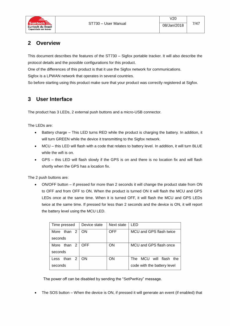
The 2 push buttons are:
ON/OFF button – if pressed for more than 2 seconds it will change the product state from ON
to OFF and from OFF to ON. When the product is turned ON it will flash the MCU and GPS
LEDs once at the same time. When it is turned OFF, it will flash the MCU and GPS LEDs
twice at the same time. If pressed for less than 2 seconds and the device is ON, it will report
the battery level using the MCU LED.
Time pressed Device state Next state LED
More than 2
seconds
ON OFF MCU and GPS flash twice
More than 2
seconds
OFF ON MCU and GPS flash once
Less than 2
seconds
ON ON The MCU will flash the
code with the battery level
The power off can be disabled by sending the “SetPwrKey” message.
The SOS button – When the device is ON, if pressed it will generate an event (if enabled) that

ST730 – User Manual
V20
8/47 08/Jan/2018
can be sent to the Sigfox network.
The micro-USB connector has 2 main functions:
To charge the internal battery. While charging the battery LED will turn on while the battery is
being charged. The battery charge will stop, if the temperature inside the battery rises above
safety.
To connect to a PC for device configuration. When connected to the PC USB, it will establish
a serial communication interface and the user can use the Synctrack software to configure the
device.
4 Features
4.1 Tracking The tracking features is mainly designed to allow the periodically report of data.
The user can configure:
The report interval. The interval can be set from 1 to 60000 minutes. If the interval is set to 0,
the tracking module is disabled
The data types sent. All the protocol available data types of
In the case where the data to be sent is one of the GPS types, the device will turn on the GPS chipset
30 seconds before in order to get a fix and update the satellites information.
In the case where the date to be sent is one of the Wifi types, the device will turn on the Wifi chipset,
5 seconds before so that it can scan the available networks.
4.2 Virtual ignition
The Virtual ignition feature is designed to allow the user to configure 2 intervals: one if it is moving and
the other when it is stopped. It used the 3D accelerometer to distinct between moving and not moving
states.
Here the user can configure:
Interval to send messages while the device is moving
Acceleration (in g) that the device uses to detect that is going from stopped to moving
Debounce interval to detect that is going from stopped to moving
Acceleration (in g) that the device uses to detect that is going from moving to stopped
Debounce interval to detect that is going from moving to stopped
At startup, the device is at a stop state. If it detects accelerometer events for more than the debounce
interval, then it changes to the moving state.
ST730 – User Manual
V20
9/47 08/Jan/2018
In the moving state, the device is looking for a debounce interval without accelerometer events. When
this interval is detected is goes to the stopped state.
The features can also trigger the “ignition on” and “ignition off” events.
When the virtual ignition feature is enabled, the device will report the “moving” state periodic message
with a message id “0x21”.
The current consumption of the device will increase a little since the accelerometer sensor stays
functional when the feature is enabled.
4.3 Temperature monitoring
This feature allows the user to configure a temperature band defined by a high and a low temperature
threshold. The device will monitor the measured temperature and can issue the following events:
Temperature above the threshold
Temperature below threshold
Temperature back to range. The device was out of the range and is back to between the
thresholds.
The sampling time is 20 seconds.
4.4 Maximum number of messages per day This feature allows you to configure the maximum number of messages sent by the device per day.
When configuring this parameter, the device will check if, using the current tracking interval, the
number of messages will exceed the configuration. In this case, the device will reconfigure the
tracking interval to the minimum possible interval respecting the maximum number of messages per
day.
If the maximum number of messages per day is already configured and you try to configure the
tracking interval to a lower interval than the minimum interval allowed, the configuration will be denied.
Configuring the value zero in the maximum number of messages per day will allow any tracking
interval.
In order to protect this configuration, an 8 digits hexadecimal (0-9, A-F) validation key is necessary to
perform this command. By default, the validation key is “00000000”.
The user can set a costumer key that acts as a seed into the algorithm to calculate the validation key.
The main use case is where the user needs to limit the number of messages the device uses, so that
it does not exceed contracted communications plan.
Example:
The contracted plan is for 50 messages a day.
The possible configurations are:

ST730 – User Manual
V20
10/47 08/Jan/2018
- Tracking interval greater than 29 minutes
- Virtual ignition ON interval greater than 29 minutes.
If the one of the data types in the tracking message is “Double Wifi”, then the minimum interval
will increase to 58 minutes.
Procedure:
1. Set up a customer key to protect the configurations using
AT^ST730CMD;;02;SetCustomerKey
2. Set the maximum number of messages using AT^ST730PKT to 50 messages:
AT^ST730PKT;;02;50;00000000, where “00000000” is the customer key.
3. If the configured intervals (tracking and virtual ignition) are outside if the limit, the device will
set new intervals according to this configuration.
If the customer key is lost, please contact Suntech for the recovery procedure.
4.5 Fences
This device has 2 types of fences. One that based on Wifi access points and another that is based in
GPS locations. In order for the fences feature to work, both the fence has to configured and the at
least one of the fences possible events has to be also enabled. For examples, for the Wifi fence
configuration, one or both of the events ”entering wifi fence” or “leaving the wifi fence” have to be
enabled.
A total of 10 fences are possible to be configured.
The GPS fences are evaluated continuously while the GPS is valid.
Normally the GPS is only on during the tracking interval, however the user can trigger the device to
turn on the GPS at different interval by setting the “check fence interval” configuration. Caution that
the effective interval is the one from last configured message. If the interval is set to zero, the fences
will only be evaluated during the tracking interval.
In order for the fence to work, the event also have to be enabled. In case of the GPS fences, the GPS
fence in and/or out events and in case of the wifi fences, the wifi fence in and/or out events.
4.6 GPS configuration
In order to make the device more flexible some options to configure the GPS behavior are available.
The options are:
- GPS interval the chipset stays on
- GPS chipset state between intervals
The interval the GPS chipset stays on limits the time the device will keep the GPS on. The device will
turn on the GPS chipset this amount of time before the tracking interval. So for example, if the
tracking time is 10 minutes and the GPS interval is set to 90 seconds, the GPS chipset will be on 90
ST730 – User Manual
V20
11/47 08/Jan/2018
seconds before the 10 minutes elapses.
If the interval is set to zero, it will enter an auto-adjust mode. In this mode the device will start with a 5
minutes GPS interval and will adjust this timing according to the time to fix. Therefore, if it is having a
fast time to fix, it will decrease the interval. Likewise, if it cannot have a fix, it will increase the interval.
Caution that this adjustment is made according to the previous condition. So if the device moves from
a more favorable GPS fix condition to a worst GPS fix condition, the device may take a couple of
messages to adjust the GPS intervals to the current condition.
4.7 Events
4.7.1 Power On/Off
When enabled these events will trigger the device to send a message to the network.
The power on event happens when the power button is pressed for more than 2 seconds and the
device is off.
The power off event happens when the power button is pressed for more than 2 seconds and the
device is on.
4.7.2 SOS
The SOS event happens when the SOS button is pressed for more than 1 seconds and the device is
on.
4.7.3 Hall sensor
This event is triggered when the device detect that a magnetic field starts or stop to be present.
4.7.4 Battery change
The Battery start-charging event happens when the device detects that the micro-usb is connected.
The Battery stop-charging event happens when the device detects that the micro-usb is disconnected.
4.7.5 Movement
This event is triggered when the sensor detects a movement. After an event is triggered it will disable
the sensor for the next 60 seconds. Only after that time a new event can be triggered.
4.7.6 Jamming
This event is triggered when the GPS detects interference in the receiving signal. This event will only
work if the GPS is on, it has a fix and a jammer is turned on. This event will not work if the jammer is
turned on when the GPS is off or in sleep or the GPS was no fix. So to use the feature, the GPS
configuration must keep the GPS on all the time.
ST730 – User Manual
V20
12/47 08/Jan/2018
4.7.7 Fences
The fence feature can generate 2 types of events. The “IN” event happens when the device goes from the “outside fence” condition to a “inside fence” condition. Likewise the “OUT” event happens when the device goes from the “inside fence” condition to a “outside fence” condition.
4.7.8 Low battery
This event is triggered when the device measures a low battery condition.
4.7.9 Virtual ignition
The device can trigger the “ignition on” and “ignition off” events when it detect transitions from a “stop”
state to a “moving” state.
4.7.10 Temperature
The device can trigger: - “low temperature” event - “high temperature” event - “Normal temperature” event
The “low temperature” event is trigger when the device was inside the temperature band and detects that the temperature has reached the low temperature threshold for more that the configured debounce time. Likewise the “high temperature” event is trigger when the device was inside the temperature band and detects that the temperature has reached the high temperature threshold for more that the configured debounce time. The “normal temperature” event is trigger to report that the device has returned to the configured temperature band after a low or high temperature condition.
5 Sigfox Protocol
The Sigfox module is able to transmit a maximum of 12 bytes.
The format of the information sent is:
Message type Payload
Each Message type has a specific format for the payload field. The payload is defined as a set of data types followed by the data itself:
Data Type
Data ... Data Type
Data
5.1 Data types
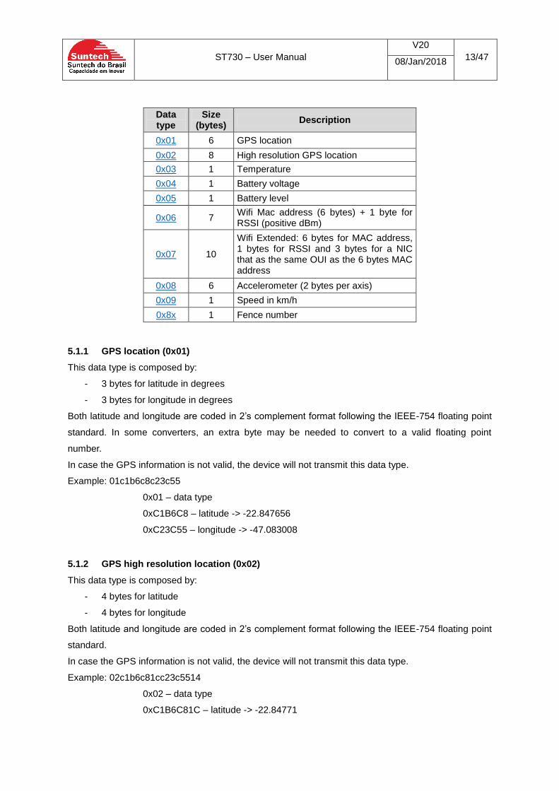
The following table shows the possible data types:
ST730 – User Manual
V20
13/47 08/Jan/2018
Data type
Size (bytes)
Description
0x01 6 GPS location
0x02 8 High resolution GPS location
0x03 1 Temperature
0x04 1 Battery voltage
0x05 1 Battery level
0x06 7 Wifi Mac address (6 bytes) + 1 byte for RSSI (positive dBm)
0x07 10
Wifi Extended: 6 bytes for MAC address, 1 bytes for RSSI and 3 bytes for a NIC that as the same OUI as the 6 bytes MAC address
0x08 6 Accelerometer (2 bytes per axis)
0x09 1 Speed in km/h
0x8x 1 Fence number
5.1.1 GPS location (0x01)
This data type is composed by:
- 3 bytes for latitude in degrees
- 3 bytes for longitude in degrees
Both latitude and longitude are coded in 2’s complement format following the IEEE-754 floating point
standard. In some converters, an extra byte may be needed to convert to a valid floating point
number.
In case the GPS information is not valid, the device will not transmit this data type.
Example: 01c1b6c8c23c55
0x01 – data type
0xC1B6C8 – latitude -> -22.847656
0xC23C55 – longitude -> -47.083008
5.1.2 GPS high resolution location (0x02)
This data type is composed by:
- 4 bytes for latitude
- 4 bytes for longitude
Both latitude and longitude are coded in 2’s complement format following the IEEE-754 floating point
standard.
In case the GPS information is not valid, the device will not transmit this data type.
Example: 02c1b6c81cc23c5514
0x02 – data type
0xC1B6C81C – latitude -> -22.84771
ST730 – User Manual
V20
14/47 08/Jan/2018
0xC23C5514 – longitude -> -47.083084
5.1.3 Temperature (0x03)
This data type is coded as:
- If the value is less than 127, temperature = value/2;
- If the value is greater than 127, temperature = (256-value) / 2
The temperature is in degrees Celsius.
Example: 0328
0x03 – data type
0x28 – temperature = 0x28/2 = 20 C
03F6
0x03 – data type
0xF6 – temperature = (256 – 246)/2 = -5 C
5.1.4 Battery voltage (0x04)
This data type is coded with a 0.1 volts resolution.
Example: 0422
0x04 – data type
0x22 – voltage = 34/0.1 = 3V4
5.1.5 Battery level (0x05)
This data type is the battery charge percentage.
Example: 053C
0x05 – data type
0x3C – 60%
5.1.6 Wifi MAC address (0x06)
This data type is the MAC address of the strongest access point that was scanned followed by the
signal strength.
Example: 06ACC6629E5D6832
0x06 – data type
ACC6629E5D68 – MAC address
0x32 - signal strength -> -50 dBm
There is also the option to send 2 MAC address. In this case the device will send 2 consecutive
messages with this data type with the 2 strongest wifi access points.
5.1.7 Wifi Extended (0x07)
This data type is the MAC address of the strongest access point with the same format as “Wifi MAC
ST730 – User Manual
V20
15/47 08/Jan/2018
address” data type followed by 3 more bytes with the NIC of another access point.
The MAC address is composed by 2 groups of 3 bytes. The first is the OID and is unique per
manufacturer and the other is the NIC that is unique per device.
So in this data type the second wifi mac address is the OID of the first MAC and the NIC transmitted.
Example: 07ACC6629E5D6833186251
0x07 – data type
ACC6629E5D68 – MAC address – OID- ACC662
0x33 - signal strength -> -50 dBm
186251 – 2nd
MAC address -> ACC662186251
5.1.8 Accelerometer (0x08)
This data type reports the values sampled by the accelerometer 3D sensor. Each axis takes 2 bytes.
The resolution is 3.91mg
Example: 08FFF9FF4700C7
0x08 – data type
FFF9 – x axis -> -7 -> 27 mg
FF47 – y axis -> - 185 -> -723 mg
00C7 – z axis -> 199 -> 778 mg
5.1.9 Speed (0x09)
This data type reports the speed value in km/h.
Example: 0925
0x09 – data type
0x25 – speed -> 37 km/h
5.1.10 Fence number (0x8X)
This data type reports the fence number. The fence number is the lower nibble of the byte.
Example: 0x81
0x8x – data type
0x01 – fence number 1
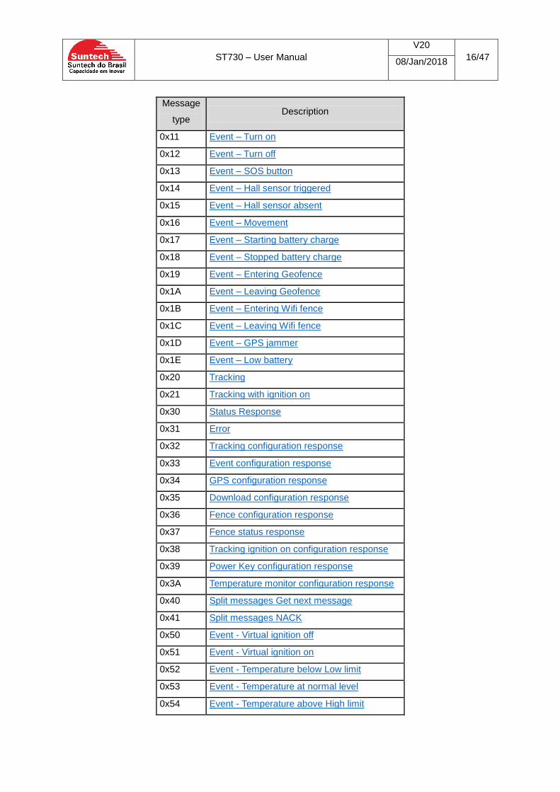
5.2 Message types This field has the size of 1 byte. The possible values are:
ST730 – User Manual
V20
16/47 08/Jan/2018
Message
type Description
0x11 Event – Turn on
0x12 Event – Turn off
0x13 Event – SOS button
0x14 Event – Hall sensor triggered
0x15 Event – Hall sensor absent
0x16 Event – Movement
0x17 Event – Starting battery charge
0x18 Event – Stopped battery charge
0x19 Event – Entering Geofence
0x1A Event – Leaving Geofence
0x1B Event – Entering Wifi fence
0x1C Event – Leaving Wifi fence
0x1D Event – GPS jammer
0x1E Event – Low battery
0x20 Tracking
0x21 Tracking with ignition on
0x30 Status Response
0x31 Error
0x32 Tracking configuration response
0x33 Event configuration response
0x34 GPS configuration response
0x35 Download configuration response
0x36 Fence configuration response
0x37 Fence status response
0x38 Tracking ignition on configuration response
0x39 Power Key configuration response
0x3A Temperature monitor configuration response
0x40 Split messages Get next message
0x41 Split messages NACK
0x50 Event - Virtual ignition off
0x51 Event - Virtual ignition on
0x52 Event - Temperature below Low limit
0x53 Event - Temperature at normal level
0x54 Event - Temperature above High limit

ST730 – User Manual
V20
17/47 08/Jan/2018
5.2.1 Tracking (0x20)
The ID 0x20 identifies the tracking message type and is followed by data types configured.
Example:
Tracking message
Message: 2002c1b6df66c23c17620428
Decoding:
20 – tracking message type
02 – high precision GPS data type
c1b6df66 – latitude in 2’s complement -> -22,8590813
c23c1762 – longitude in 2’complement -> -47,0228348
04 – Battery voltage type
28 – Battery voltage, 0x28 -> 40 decimal -> 40*0.5 = 20 degrees
5.2.2 Tracking with ignition on (0x21)
The ID 0x21 identifies the tracking message type where the virtual ignition feature identifies that the
device is moving.
5.2.3 Status Response (0x30)
This message can be requested by a Command Request (0x01)
The payload of Status Response message has the following format:
Name Size Description
Battery Voltage 1 Battery voltage with 0.1 volts resolution
I/O Status 1 bit 0 – external power bit 1 – Hall sensor
Firmware Version 6 Firmware version string
Example:
Message: 302901333032543032
30 - Status response
29 – Battery voltage, 4.1V
01- External Power enabled, Hall Sensor disabled
333032543032 - 302T02
5.2.4 Error (0x31)
The Error message does not have a payload
5.2.5 Tracking configuration response (0x32)
This message can be requested by a Command Request (0x01)

ST730 – User Manual
V20
18/47 08/Jan/2018
The payload of Tracking configuration response message has the following format:
Name Size Description
Tracking interval 2 Tracking interval in minutes
Data type 0 1 Data type configured in slot 0
Data type 1 1 Data type configured in slot 1
Data type 2 1 Data type configured in slot 2
Data type 3 1 Data type configured in slot 3
Example:
Message: 32000102040000
32 – Tracking configuration response
29 – Battery voltage, 4.1V
02 - High Precision GPS
04 - Battery Voltage
00 – None
00 - None
5.2.6 Event configuration response (0x33)
The Event configuration response message has the following format:
Message type
Event Number
... Event
Number
The device will send only the event numbers that are enabled. If the size of this message exceed 12
bytes, more than 1 messages will be sent to report all enabled events.
Here are the possible event numbers:
Event Number Event name
0 Event – Turn on
1 Event – Turn off
2 Event – SOS button
3 Event – Hall sensor triggered
4 Event – Hall sensor absent
5 Event – Movement
6 Event – Starting battery charge
7 Event – Stopped battery charge
8 Event – Entering Geofence
9 Event – Leaving Geofence
10 Event – Entering Wifi fence
11 Event – Leaving Wifi fence
12 Event – GPS jammer
13 Event – Low battery
14 Event - Virtual ignition off

ST730 – User Manual
V20
19/47 08/Jan/2018
15 Event - Virtual ignition on
16 Event - Temperature below Low limit
17 Event - Temperature at normal level
18 Event - Temperature above High limit
Example:
Message: 33000102
33 – Event configuration response
00 – Event – Turn on
01 – Event – Turn off
02 – Event – SOS button
5.2.7 GPS configuration response (0x34)
The GPS configuration response payload has the following format:
Name Size Description
GPS acquisition time no fix 2
time in seconds to wakeup the GPS before the tracking message, if there is no fix
GPS acquisition time with fix 2
time in seconds to wakeup the GPS before the tracking message, if there is fix
Flags 1
bit 0 – GPS state between tracking messages if no fix, bit 1 – GPS state between tracking messages if fix, bit 2 – Wifi backup
Example:
Message: 340000000000
34 – GPS configuration response
0000 – Acquisition time, no fix
0000 – Acquisition time, with fix
00 – Wifi backup disabled, Sleep if have fix disabled, sleep if have no fix disabled
5.2.8 Download configuration response (0x35)
The Download configuration response payload has the following format:
Name Size Description
Check Interval 1 time, in hours, to check for downloads
Flags 1
bit 0 – force the message download, do not wait until next Tx bit 1 – check for download every message
ST730 – User Manual
V20
20/47 08/Jan/2018
Example:
Message: 350002
35 – Download configuration response
00 – check time
02 – Force download disabled, check every message enabled
5.2.9 Fence configuration response (0x36)
The Fence configuration response paylod has the following format
Name Size Description
Events bit field 3
2 bits per fence(10 fences): 00 – disabled 01 – In event 10 - out event 11 – in/out events The last 4 bits are reserved
Example:
Message: 36 2D 00 00
Payload Binary: 0010 1101 0000 0000 0000 0000
Fence #0 – 00 – disabled
Fence #1 – 10 – Out event enabled
Fence #2 – 11 – In/Out events enabled
Fence #3 – 01 – IN event enabled
…
5.2.10 Fence Status response (0x37)
The Fence Status response has a variable payload that depends on the first payload byte (Fence
number and control). If the fence is disabled, the device will just send the message id and the first
byte (“Fence Number and control”).
GPS fence type:
Name Size Description

ST730 – User Manual
V20
21/47 08/Jan/2018
Fence Number and control 1
4 bits: Fence number 2 bits: 00 – disabled 01 – In event 10 - out event
11 – in/out events 2 bits: 00 - GPS fence 01 - Wifi fence
Latitude 4 GPS fence center latitude (between -
90.0 and +90.0). IEEE 754
Longitude 4 GPS fence center longitude (between
-180.0 and +180.0). IEEE754
Radius 2 GPS fence radius in meters (between
100 and 65000)
Example:
Message: 370cc1b80000c23c00000064
37 - Fence Status response
0C - In bits, (0000)Fence number 0, (11) In/out event, (00)GPS fence
c1b80000 - Latitute (-23)
c23c0000 - Longitute(-47)
0064 - Radius(100)
Wifi fence:
Name Size Description
Fence Number and control 1
4 bits: Fence number 2 bits: 00 – disabled 01 – In event 10 - out event
11 – in/out events 2 bits: 00 - GPS fence 01 - Wifi fence
Wifi MAC Address OUI 3 Wifi MAC Address OUI
Wifi MAC Address NIC 3 Wifi MAC Address OUI
Example:
Message: 370d909f33bbc214
37 - Fence Status response
0d - In bits, (0000)Fence number 1, (11) In/out event, (01)Wifi fence
909f33 - Wifi MAC Address OUI
bbc214 - Wifi MAC Address NIC
5.2.11 Tracking ignition on configuration response (0x38)
The payload of this message is given by:
ST730 – User Manual
V20
22/47 08/Jan/2018
Name Size Description
Tracking interval with ignition on
2 Tracking interval in minutes
Data type 0 1 Data type configured in slot 0
Data type 1 1 Data type configured in slot 1
Data type 2 1 Data type configured in slot 2
Data type 3 1 Data type configured in slot 3
Example:
Message: 38000502040000
38 – Tracking ignition on configuration response
0005 – Tracking time with ignition on
02 - High Precision GPS
04 - Battery Voltage
00 – None
00 - None
5.2.12 Power Key configuration response (0x39)
The payload of this message is given by:
Name Size Description
Power key enabled 1 01 - Enabled 00 - Disabled
Example:
Message: 3901
39 – Power key configuration response
01 – Power key feature enabled
5.2.13 Temperature monitor configuration response (0x3A)
The payload of this message is given by:
Name Size Description
High Setpoint 2 High setpoint in °C x 10
Low Setpoint 2 Low setpoint in °C x 10
Debounce 2 Debounce in seconds
Example:
Message: 3a0190ff9c003c
3a – Temperature monitor configuration response
0190– High setpoint(40ºC)
ff9c - Low setpoint(-10ºC)
ST730 – User Manual
V20
23/47 08/Jan/2018
003c – Debounce(60s)
5.2.14 Get Message (0x40)
The Get Message does not have a payload. The device sends this message to force a Sigfox
download message. It can be sent:
when the device receives a Split command message with index of message different of total
number of message in order to force a download of the next Split Command message;
when the force download feature is enabled and the check download timer expired.
5.2.15 Split Messages NACK (0x41)
The Split Messages NACK message does not have a payload. The device sends this message when
an error in a Split message occurred.
5.3 Sigfox commands
The Sigfox module is able to receive a maximum of 8 bytes.
The format of the information sent is:
Command type Payload
Each Command type has a specific format for the payload field.
The following commands are available to send it to device:
Command type
Description
0x01 Command Request
0x02 Tracking Configuration
0x03 Event Configuration
0x04 GPS Configuration
0x05 Download Configuration
0x06 Fence Status Configuration
0x07 Sigfox Max. Messages per day configuration
0x08 Split message
0x09 Fence Configuration
0x0A Virtual Ignition Enabling
0x0B Virtual ignition Parameters Configuration
0x0C Temperature Monitor Configuration
0x0D Power key Configuration

ST730 – User Manual
V20
24/47 08/Jan/2018
5.3.1 Command Request (0x01)
The Command Request payload is a single byte, a parameter that indicates the desired request. The
following table gives all possible parameters:
Parameter Description
0x01 Request a Status Response message
0x02 Request a device reboot
0x03 Request the device to restore the default configurations
0x04 Request the Tracking configuration response message
0x05 Request the Event configuration response message
0x06 Request the GPS configuration response message
0x07 Request the Download configuration response message
0x08 Request the Fences configuration response message
0x09 Request the Fences status response message
0x0A Request the Tracking ignition on configuration response
0x0B Request the Power Key configuration response message
0x0C Request the Temperature monitor configuration response message
Example: 0101000000000000
01 – Command Request
01 – Request a Status Response message
000000000000 – Byte stuffing
5.3.1.1 Request the Fences status response message(0x09)
This command uses the next byte as another parameter which is the desired fence number.
Example: 0109000000000000 (Request Fence 0 status response)
0109090000000000 (Request Fence 9 status response)
5.3.2 Tracking Configuration (0x02)
The payload of this message is given by:
Name Size Description
Tracking interval 2 Tracking interval in seconds
Data type 0 1 Data type configured in slot 0
Data type 1 1 Data type configured in slot 1
Data type 2 1 Data type configured in slot 2
Data type 3 1 Data type configured in slot 3
Example: 0200030000000400
02 – Tracking Configuration
0003 – 3 minutes interval
00 – data type #0 – Empty
ST730 – User Manual
V20
25/47 08/Jan/2018
00 – data type #1 – Empty
00 – data type #2 – Empty
04 – data type #3 – Battery voltage
00 – Byte stuffing
5.3.3 Event Configuration (0x03)
The payload of this message is given by:
Name Size Description
Event Number 1 Number of event
Event Enable 1 01 - Enable 00 - Disable
Data type 0 1 Data type configured in slot 0
Data type 1 1 Data type configured in slot 1
Data type 2 1 Data type configured in slot 2
Data type 3 1 Data type configured in slot 3
Example: 0300010000000400
03 – Event Configuration
00 – Event number(Event – Turn on)
01 – Event enabled
00 – data type #0 – Empty
00 – data type #1 – Empty
00 – data type #2 – Empty
04 – data type #3 – Battery voltage
00 – Byte stuffing
5.3.4 GPS Configuration (0x04)
The payload of this message is given by:
Name Size Description
GPS acquisition time no fix 2 time in seconds to wakeup the GPS before the tracking message, if there
is no fix
GPS acquisition time with fix 2 time in seconds to wakeup the GPS before the tracking message, if there
is fix
ST730 – User Manual
V20
26/47 08/Jan/2018
Flags 1
- bit 0 – GPS state between tracking messages if no fix,
- bit 1 – GPS state between tracking messages if fix,
- bit 2-3 - Wifi backup (00 – no backup; 01 – wifi backup; 02 – double wifi backup)
Example: 040078003C010000
04 - GPS configuration
0078 – 0x0078 is 120 seconds
003C – 0x003C is 60 seconds
01 – GPS on if no fix, GPS off if fix, no Wifi backup
0000 – Byte stuffing
5.3.5 Download Configuration (0x05)
The payload of this message is given by:
Name Size Description
Check Interval 1 time, in hours, to check for downloads
Flags 1
bit 0 – force the message download, do not wait until next Tx
bit 1 – check for download every message
Example: 0500020000000000
05 - Download configuration
00 – Time to check download
02 – Force download disabled, Check every message enabled
0000000000– Byte stuffing
5.3.6 Fence Status Configuration (0x06)
The payload of this message is given by:
Name Size Description
Fence Number 1 Number of the fence
Fence Status 1 01 - Enable 00 - Disable
Example: 0600010000000000
06 – Fence Status Configuration
00 – Number of the fence
ST730 – User Manual
V20
27/47 08/Jan/2018
01 – Fence enabled
0000000000– Byte stuffing
5.3.7 Sigfox Max. tracking messages per day configuration (0x07)
The payload of this message is given by:
Name Size Description
Number of messages 1 Max. tracking messages per day
Verification Key 4 Verification key to validate the
command
Example: 0700AABBCCDD0000
07 – Sigfox Max. tracking messages per day Configuration
00 – Max. number of tracking messages per day (0 is unlimited)
AABBCCDD – Verification key(This is key is not valid, it is just an example)
0000– Byte stuffing
5.3.8 Split message (0x08)
The payload of this message is given by:
Name Size Description
Split Control 1
4bits -Index of the message being transmitted
4bits - Total number of split messages
Message Variable (Max 6)
Part of the message
The maximum number of split messages is 3.
As an example, suppose you need to send the following message, that exceed 8 bytes:
090CC1B8FBE7C23DD2F20064 (12 bytes)
So the message can be divided in 2 messages:
0812090CC1B8FBE7 08 – Split message Type
1 – Message index
2- Total number of messages
090CC1B8FBE7 – first 6 bytes
0822C23DD2F20064
08 – Split message Type
2 – Message index
ST730 – User Manual
V20
28/47 08/Jan/2018
2- Total number of messages
C23DD2F20064– last 6 bytes
5.3.9 Fence Configuration (0x09)
The payload of this message can assume two different formats, however, both exceed 8 bytes, so the
only way to send this kind of message is to use 2 Split messages.
If it is a GPS fence, the payload has the following format:
Name Size Description
Fence Number and control 1
4 bits: Fence number 2 bits: 00 – disable 01 – In event 10 - out event
11 – in/out events 2 bits: 00 - GPS fence 01 - Wifi fence
Latitude 4 GPS fence center latitude (between -
90.0 and +90.0). IEEE 754
Longitude 4 GPS fence center longitude (between
-180.0 and +180.0). IEEE754
Radius 2 GPS fence radius in meters (between
100 and 65000)
Example: 090CC1B8FBE7C23DD2F20064
09 – Fence Configuration
0C – Fence 0, IN/OUT event enabled, GPS fence
C1B8FBE7– Latitude (-23,123°)
C23DD2F2– Longitude (-47,456°)
0064 – Radius(100m)
For a Wifi fence, the payload has the following format:
Name Size Description
Fence Number and control 1
4 bits: Fence number 2 bits: 00 – disable 01 – In event 10 - out event
11 – in/out events 2 bits: 00 - GPS fence 01 - Wifi fence
Wifi MAC Address OUI 3 Wifi MAC Address OUI
Wifi MAC Address NIC 3 Wifi MAC Address OUI
Example: 090D112233aaBBdC
09 – Fence Configuration
ST730 – User Manual
V20
29/47 08/Jan/2018
0C – Fence 0, IN/OUT event enabled, Wifi fence
112233 – Wifi MAC Address OUI
aaBBdC – Wifi MAC Address NIC
5.3.10 Virtual Ignition Enabling (0x0A)
The payload of this message is given by:
Name Size Description
Virtual Ignition enable 1 01 - Enable 00 - Disable
Tracking time with ignition on 2 Tracking time, in seconds, with virtual
ignition on
Example: 0A01003C00000000
0A – Virtual Key Enabling
01 – Feature enabled
003C – Tracking time with ignition on(60s)
00000000– Byte stuffing
5.3.11 Virtual ignition Parameters Configuration (0x0B)
The payload of this message is given by:
Name Size Description
Threshold On 1 Accelerometer threshold, in 1/255g,
to consider virtual ignition on
Debounce On 2 Debounce, in seconds, to consider
virtual ignition on
Threshold Off 1 Accelerometer threshold, in 1/255g,
to consider virtual ignition off
Debounce Off 2 Debounce, in seconds, to consider
virtual ignition off
Example: 0B05000A05003C00
0B – Virtual ignition Parameters Configuration
05 – Threshold On
000A – Debounce On(10s)
05 – Threshold Off
003C – Debounce Off (60s)
00 – Byte stuffing
ST730 – User Manual
V20
30/47 08/Jan/2018
5.3.12 Temperature Monitor Configuration (0x0C)
The payload of this message is given by:
Name Size Description
High Setpoint 2 High setpoint in °C x 10
Low Setpoint 2 Low setpoint in °C x 10
Debounce 2 Debounce in seconds
Example: 0C0190FF9C003C00
0C – Temperature Monitor Configuration
0190 – High Setpoint(40°C)
FF9C – low Setpoint(-10°C)
003C – Debounce
00– Byte stuffing
5.3.13 Power key Configuration (0x0D)
The payload of this message is given by:
Name Size Description
Power key enabled 1 01 - Enabled 00 - Disabled
Example: 0D01000000000000
0D – Power Key Configuration
01 – Feature enabled
000000000000– Byte stuffing
6 USB Protocol
6.1 Available commands
Command Description
AT Serial communication check
AT^ST730TCK
Sets the tracking configurations (tracking interval, data to be send in the message)
AT^ST730EVT
Event configuration (enable/disable and data to be sent in the message)
AT^ST730GPS Configure GPS behavior
AT^ST730DWL Download configuration
AT^ST730FNC Fence configuration

ST730 – User Manual
V20
31/47 08/Jan/2018
AT^ST730PKT
Configure maximum number of Sigfox message per day
AT^ST730VIGN Configure virtual ignition parameters
AT^ST730TEMPMON Configure Temperature monitor parameters
AT^ST730CMD;;02;StatusReq Requests the product status
AT^ST730CMD;;02;ReqSigfoxID Returns the Sigfox ID
AT^ST730CMD;;02;ReqSigfoxPAC Returns the Sigfox PAC
AT^ST730CMD;;02;ReqSigfoxRCZ
Returns the Sigfox RCZ
AT^ST730CMD;;02;ReqFwUpdate Enable the device firmware update
AT^ST730CMD;;02;ReqReset
Reset the setting to the default values
AT^ST730CMD;;02;ReqReboot
Reboots the device
AT^ST730CMD;;02;ReqTCK
Request the configured tracking parameters
AT^ST730CMD;;02;ReqEVT
Request the configured enabled event configurations
AT^ST730CMD;;02;ReqDWL Returns the download configuration
AT^ST730CMD;;02;ReqGPS Returns GPS paramaters
AT^ST730CMD;;02;ReqSigfoxPacket
Returns the maximum Sigfox number of messages per day configured
AT^ST730CMD;;02;ReqPKey Returns the Pkey used to calculate the Reset Key
AT^ST730CMD;;02;SetCustomerKey Sets the unique customer password
AT^ST730CMD;;02;ReqVign Returns Virtual ignition parameters
AT^ST730CMD;;02;ReqTempMon Returns Temperature monitor parameters
AT^ST730CMD;;02;ReqBootloader Returns bootloader version
AT^ST730CMD;;02;SetPwrKey Sets the power key feature
AT^ST730CMD;;02;ReqPwrKey Returns power key configuration
AT^ST730CMD;;02;ReqFNC Returns the fences configured
6.2 Commands detail
6.2.1 AT
Example: AT
Response: OK
6.2.2 AT^ST730TCK
This command configures the device tracking messages intervals.
Name Min Max Description
Tracking interval 0 60000 Interval between tracking messages. If the virtual ignition is enable, this is the interval for the ignition off condition
Data type 1 - - Data types

ST730 – User Manual
V20
32/47 08/Jan/2018
Data type 2 - - Data types
Data type 3 - - Data types
Data type 4 - - Data types
Example: AT^ST730TCK;;02;60;2;0;0;0
60 - tracking interval in minutes (0 to 60000)
2 - data to send in message - field 1
0 - data to send in message - field 2
0 - data to send in message - field 3
0 - data to send in message - field 4
Response: ST730TCK;Res;123456789;60;2;0;0;0
6.2.3 AT^ST730EVT
This command configures the device events.
Name Min Max Description
Event - - Events
State 0 1 Enable (1) or Disable (0)
Data type 1 - - Data types
Data type 2 - - Data types
Data type 3 - - Data types
Data type 4 - - Data types
Example: AT^ST730EVT;;02;1;1;4;0;0;0
1 - Sensor id (the sensor ID is defined in the event type table)
1 - Enable/disable
4 - data to send in message - field 1
0 - data to send in message - field 2
0 - data to send in message - field 3
0 - data to send in message - field 4
Response: ST730EVT;Res;123456789;1;1;4,0;0;0
6.2.4 AT^ST730GPS
This command setups the GPS behavior of the device.
Name Min Max Description
GPS acquisition time no fix 0 32000 Time in seconds to wakeup the GPS before the tracking message, if there
is no fix

ST730 – User Manual
V20
33/47 08/Jan/2018
GPS status between acquisitions, with no GPS fix
0 1 0 – the GPS stays off 1 – the GPS goes to sleep
GPS acquisition time with fix 0 32000 time in seconds to wakeup the GPS before the tracking message, if there
is fix
GPS status between acquisitions, with GPS fix
0 1 0 – the GPS stays off 1 – the GPS goes to sleep
GPS backup 0 2
0 – No backup 1 – Wifi backup – it will send 1 MAC address 2 – Double wifi backup – it will send 2 MAC address
Example: AT^ST730GPS;;02;60;1;30;0;0
60 – time to wakeup the GPS before the tracking message, if there is no fix
1 – between tracking messages, the GPS stays in sleep
30 – time to wakeup the GPS before the tracking message, if there is a fix
0 - between tracking messages, the GPS is turned off
0 – Disable the wifi backup feature
Response: ST730GPS;Res;123456789;60;1;30,0;0
6.2.5 AT^ST730DWL
This command setups the downlink behavior of the device.
Name Min Max Description
Download interval 0 48
Time interval (in hours) that the device will use to check for download messages. A 0 value will disable the download check.
Force download message 0 1
If set, it will trigger a dummy message to check the download, when the download interval is reached. Otherwise, it will wait until the next message.
Request download every Tx 0 1 If set, it will check for a download every transmitted message.
Example:
AT^ST730DWL;;02;12;0;0
12 – the device will check every 12 hours if there are messages in the downlink
path.
0 – It will wait for the next transmission, after the download timer expires, to enable
the downlink
0 – disable the downlink in every transmitted message

ST730 – User Manual
V20
34/47 08/Jan/2018
Response: ST730DWL;Res;123456789;12;0;0
6.2.6 AT^ST730FNC
Configuration to, one by one, set the fence.
Name Min Max Description
Fence number 0 9 Fence number to configure
Event to monitor 0 3
0 – fence disabled 1 – monitor IN event 2 – monitor OUT event 3 – monitor IN and OUT events
Fence type 0 1 0 – GPS fence 1 – Wifi fence
Latitude -90.0 +90.0 Latitude in degrees of the GPS fence
Longitude -180.0 +180.0 Longitude in degrees of the GPS fence
Radius 100 65000 Radius in meters of the GPS fence
MAC Address - - MAC address for the Wifi fence
Initial state 0 1 0 – start in the IN state 1 – start in the OUT state
Fence check interval 0 1440
Interval to check for the fence, if zero it will only check the fence when the GPS is ON, Otherwise it will only check when the device turns those location sources for other reasons.
Example: ST730FNC;;02;0;3;0;-23.000;-47.000;100;112233aaBBdC;1;10
0 – fence number
3 – event in and out enabled (0 – Off, 1 – IN, 2 – OUT, 3 – IN/OUT)
0 – GPS fence (0 – GPS, 1 – Wifi)
-23.00000 – Latitude (between -90.0 and +90.0)
-47.00000 – Longitude (between -180.0 and +180.0)
100 – radius in meters (between 100 and 65000)
112233aaBBdC – Wifi MAC Address(Not used in this case because it is a GPS
fence)
1 – current status(0 – IN, 1 - OUT)
10 – fence check time in minutes
Response: ST730FNC;Res;9234567890;0;3;0;-23.00000;-47.00000;100;0;1;10
6.2.7 AT^ST730PKT
This command sets the maximum number of messages a day that limits the tracking interval
configuration.
ST730 – User Manual
V20
35/47 08/Jan/2018
Name Min Max Description
Max message a day 0 250 Number of message daily limit. If it is “0” there is no limitation
Validation key - - Key to accept the configuration, Default “00000000”
Example: AT^ST730PKT;;02;100;00000000
100 – Maximum number of messages a day
00000000 – validation key
6.2.8 AT^ST730VIGN
Command to configure the virtual ignition feature.
Name Min Max Description
State 0 1 0 – Disable 1 – Enable
Virtual ignition tracking time 1 60000 Tracking interval when the virtual ignition state is ON
Ignition ON threshold 1 255 Sensor threshold (1/255g) to identify that the virtual ignition state is ON
Ignition ON debounce time 1 1800 Debounce time to identify that the virtual ignition state is ON
Ignition OFF threshold 1 255 Sensor threshold (1/255g) to identify that the virtual ignition state is OFF
Ignition OFF debounce time 1 1800 Debounce time to identify that the virtual ignition state is ON
Example: AT^ST730VIGN;;02;1;5;10;10;10;180
1 – Virtual ignition Enabled (0- Disabled, 1 Enabled)
5 – Tracking time with ignition on (1 to 60000 minutes)
10 – Ignition on threshold in 1/255 g (1 to 255)
10 – Ignition on debounce (1 to 1800 seconds)
10 – Ignition off threshold in 1/255 g (1 to 255)
180 – Ignition off debounce (1 to 1800 seconds)
Response: ST730VIGN;Res;9234567890;1;5;10;10;10;180

ST730 – User Manual
V20
36/47 08/Jan/2018
6.2.9 AT^ST730TEMPMON
Name Min Max Description
High temperature band limit -20 C +60 C High limit of the temperature band to monitor
Low temperature band limit -20 C +60 C Low limit of the temperature band to monitor
Debounce time 1 65000 Debounce time to generate the event
Example: ST730TEMPMON;;02;40;-10;180
40 – High temperature limit (-20 to 60 C)
-10 – Low temperature limit (-20 to 60 C)
60 – Debounce (1 to 65000 seconds)
Response: ST730TEMPMON;Res;9234567890;40;10;180
6.2.10 AT^ST730CMD;;02;StatusReq
Example: AT^ST730CMD;;02;StatusReq
Response: ST730StatusReq;Res;123456789;300T13;20;375
123456789 – Device serial number
300T13 – Firmware version
20 – temperature in degrees Celsius
375 – voltage in 0.1 volts resolution
6.2.11 AT^ST730CMD;;02;ReqSigfoxID
Example: AT^ST730CMD;;02;ReqSigfoxID
Response: ST730ReqSigfoxID;Res;9234567890;2C3E2D
9234567890– Device serial number
2C3E2D – Sigfox ID
6.2.12 AT^ST730CMD;;02;ReqSigfoxPAC
Example: AT^ST730CMD;;02;ReqSigfoxPAC
Response: ST730ReqSigfoxPAC;Res;9234567890;1D880954F95F57BD
9234567890– Device serial number
1D880954F95F57BD – Sigfox PAC

ST730 – User Manual
V20
37/47 08/Jan/2018
6.2.13 AT^ST730CMD;;02;ReqSigfoxRCZ
Example: AT^ST730CMD;;02;ReqSigfoxRCZ
Response: ST730ReqSigfoxRCZ;Res;9234567890;2
9234567890– Device serial number
2 – Sigfox RCZ
6.2.14 AT^ST730CMD;;02;ReqFwUpdate
Example: AT^ST730CMD;;02;ReqFwUpdate
Response: OK
6.2.15 AT^ST730CMD;;02;ReqReset
This command restores the configurations to the default values. If the max number of tracking
message a day parameter is configured, the tracking intervals are not restored to their default values.
Example: AT^ST730CMD;;02;ReqReset
Response: OK
6.2.16 AT^ST730CMD;;02;ReqReboot
Example: AT^ST730CMD;;02;ReqReboot
Response: OK
6.2.17 AT^ST730CMD;;02;ReqTCK
Example: AT^ST730CMD;;02;ReqTCK
Response: ST730TCK;Res;9234567890;10,2;4;0;0
9234567890– Device serial number
10- tracking interval in minutes
2 - data to send in message - field 1
4 - data to send in message - field 2
0 - data to send in message - field 3
0 - data to send in message - field 4
6.2.18 AT^ST730CMD;;02;ReqEVT
This commands return more than one message. For every event enabled a message will be returned.
In the example below, events number 0, 1 and 2 are enabled.
Example: AT^ST730CMD;;02;ReqEVT
Response: ST730EVT;Res;9234567890;0;1;3;0;0;0
ST730EVT;Res;9234567890;1;1;3;0;0;0
ST730 – User Manual
V20
38/47 08/Jan/2018
ST730EVT;Res;9234567890;2;1;3;0;0;0
9234567890– Device serial number
1,2,3- event number
1 - data to send in message - field 1
3 - data to send in message - field 2
0 - data to send in message - field 3
0 - data to send in message - field 4
6.2.19 AT^ST730CMD;;02;ReqDWL
The returned values follow the same layout as the command AT^ST730DWL.
Example: AT^ST730CMD;;02;ReqDWL
Response: ST730DWL;Res;9234567890;0;0;0
9234567890– Device serial number
0 - time, in hours, to check for downloads
0 - force the message download, do not wait until next Tx
0 - check for download every message
6.2.20 AT^ST730CMD;;02;ReqGPS
The returned values follow the same layout as the command AT^ST730GPS.
Example: AT^ST730CMD;;02;ReqGPS
Response: ST730GPS;Res;9234567890;90;0;60;0;0
9234567890– Device serial number
90 – GPS acquisition time with no fix
0 – turn off module when no fix(0- turn off, 1- sleep)
60 - GPS acquisition time with fix
0 – turn off module when fix(0- turn off, 1- sleep)
0 – No Wifi backup
6.2.21 AT^ST730CMD;;02;ReqSigfoxPacket
Example: AT^ST730CMD;;02;ReqSigfoxPacket
Response: ST730PKT;Res;9234567890;0
9234567890– Device serial number
0 – Maximum number of Sigfox messages per day(0 - unlimited)
6.2.22 AT^ST730CMD;;02;ReqPKey
Command to be used to reset the “costumer key”
Example: AT^ST730CMD;;02;ReqPKey
Response: ST730PKT;Res;9234567890;18813

ST730 – User Manual
V20
39/47 08/Jan/2018
9234567890– Device serial number
18813 – P key
6.2.23 AT^ST730CMD;;02;SetCustomerKey
Command to set or to reset the customer key. If there is no customer key, it sets it. If there is already
a customer key set, the user has to input here the a code that will reset back the customer code to its
default value. This code has to be requested to Suntech.
Example: AT^ST730CMD;;02;SetCustomerKey;12345678
6.2.24 AT^ST730CMD;;02;ReqVign
Example: AT^ST730CMD;;02;ReqVign
Response: ST730VIGN;Res;9234567890;0;5;10;10;10;180
9234567890– Device serial number
0 – Virtual ignition Disabled(0- Disabled, 1 Enabled)
5 – Tracking time with ignition on
10 – Ignition on threshold in 1/255g
10 – Ignition on debounce
10 – Ignition off threshold in 1/255g
180 – Ignition off debounce
6.2.25 AT^ST730CMD;;02;ReqTempMon
Example: AT^ST730CMD;;02;ReqTempMon
Response: ST730TEMPMON;Res;9234567890;40;-10;60
9234567890– Device serial number
40 – High temperature limit
-10 – Low temperature limit
60 – Debounce
6.2.26 AT^ST730CMD;;02;ReqBootloader
Example: AT^ST730CMD;;02;ReqBootloader
Response: ST730ReqBootloader;Res;9234567890;300T2
9234567890– Device serial number
301– Bootloader version
6.2.27 AT^ST730CMD;;02;SetPwrKey
Example: AT^ST730CMD;;02;SetPwrKey=1
Response: ST730PWRKEY;Res;9234567890;1
ST730 – User Manual
V20
40/47 08/Jan/2018
9234567890– Device serial number
1– Power key enabled (0- Disabled, 1 Enabled)
6.2.28 AT^ST730CMD;;02;ReqPwrKey
Example: AT^ST730CMD;;02;ReqPwrKey
Response: ST730PWRKEY;Res;9234567890;1
9234567890– Device serial number
1– Power key enabled (0- Disabled, 1 Enabled)
6.2.29 AT^ST730CMD;;02;ReqFNC
This command can return different answers
Example: AT^ST730CMD;;02;ReqFNC
If no fence is enabled, the device will return:
Response: ST730FNC;Res;9234567890;NO FENCES ENABLED
If there is some fences enabled, the response will be:
Response: ST730FNC;Res;9234567890;0;3;0;-23.00000;-47.00000;100;0;1;10
9234567890– Device serial number
0 – fence number
3 – event in and out enabled
0 – GPS fence
-23.00000 – Latitude
-47.00000 – Longitude
100 – radius
1 – current status(0 – IN, 1 - OUT)
10 – fence check time in minutes
ST730FNC;Res;9234567890;1;3;1;0.0;0.0;0;112233AABBDC;1;10
9234567890– Device serial number
1 – fence number
3 – event in and out enabled
1 – Wifi fence
0.0 – Dummy
0.0 – Dummy
0 - Dummy
112233AABBDC – Wifi MAC Address OUI and NIC
1 – current status(0 – IN, 1 - OUT)
10 – fence check time in minutes

ST730 – User Manual
V20
41/47 08/Jan/2018
7 Firmware update
The firmware of the device can be updated using the following procedure:
1. Using Synctrak, go to the “command String” tab and send the “ReqFwUpdate” command.
2. Close Synctrak.
3. The serial port should close and a “DFU” device type should be recognized. Windows may
need to install the devices drivers.
4. Open the “ST730-DFU” application, click in the “FW update” button and load the firmware dfu
file.
At the end, the application should show a “programming complete” message
8 Manufacturing commands
8.1 Commands
Command Description
AT^$PSTVer Returns the product information
AT^$ReadBarcode Returns the serial number
AT^$StartFM Start the factory mode
AT^$FT_ReqFTOpt Requests the available tests
AT^$FT_BATTADC_START Start the battery test
AT^$FT_DC_DETECT_START Start the USB external power detect test
AT^$FT_PWRKEY_START Start the power button test
AT^$FT_SOSKEY_START Start the SOS button test
AT^$FT_HALL_IC_START Start the Hall sensor test
AT^$FT_TEMPER_START Start the temperature sensor test
AT^$FT_MOTION_START Start the accelerometer test
AT^$FT_GPS_START Start the GPS test
AT^$FT_TX_START Start the Sigfox modem TX test
AT^$FT_SIGFOX_END Stop the Sigfox modem TX test
AT^$FT_WIFI_START Start the Wifi chipset test
AT^SIGCMD;;02;ReqSigfoxID Returns the Sigfox ID
AT^SIGCMD;;02;ReqSigfoxRCZ Returns the Sigfox RCZ
AT^SIGCMD;;02;ReqSigfoxID;;ReqSigfoxPAC Returns the Sigfox ID and the PAC
AT^SIGCMD;;02;ReqSigfoxPAC Returns the Sigfox PAC
AT^$ESN_WRITE Writes the product serial number
AT^$ESN_READ Returns the product serial number
AT$RADIO_PWR Sigfox modem power state
AT$RADIO Send commands to the sigfox modem
AT$WIFI_PWR Wifi chipset power state

ST730 – User Manual
V20
42/47 08/Jan/2018
AT$WIFI Send commands to the wifi chipset
AT^$FRCSLP Puts the device into sleep mode
AT^$PSTPRFSTART Profile start
AT^$PSTPRFEND Profile end
AT^ST730CMD;;02;ReqADC Requests data from the ADC
AT^ST730CMD;;02;ReqWifiUpdate Start the Wifi FW update mode
AT^ST730CMD;;02;ReqIO Requests IO data
8.1.1 AT^$PSTVer
This command returns information regarding the product, firmware version and if it is in factory mode.
Example:
$PST;Ver;ST730_SUNTECHBR_STADV_302T02;1;2;0;0;0;0;0;0;0;0;FT
ST730_SUNTECHBR_STADV – product information
302T02 – firmware version
1 – factory mode
8.1.2 AT^$ReadBarcode
This command returns the product serial number.
Example: AT^$ReadBarcode
Response: $Barcode;0000000000
8.1.3 AT^$StartFM
This command starts factory mode.
Example: AT^$StartFM
Response: OK
8.1.4 AT^SIGCMD;;02;ReqSigfoxID
Example: AT^SIGCMD;;02;ReqSigfoxID
Response: ReqSigfoxID;Res;9234567890;2C3E2D
9234567890– Device serial number
2C3E2D – Sigfox ID
8.1.5 AT^SIGCMD;;02;ReqSigfoxPAC
Example: AT^SIGCMD;;02;ReqSigfoxPAC
Response: ReqSigfoxPAC;Res;9234567890;37F878722101C0E2
9234567890– Device serial number
37F878722101C0E2 – Sigfox PAC
ST730 – User Manual
V20
43/47 08/Jan/2018
8.1.6 AT^SIGCMD;;02;ReqSigfoxRCZ
Example: AT^SIGCMD;;02;ReqSigfoxRCZ
Response: ReqSigfoxRCZ;Res;9234567890;2
9234567890– Device serial number
2 – Sigfox RCZ
8.1.7 AT^SIGCMD;;02;ReqSigfoxID;;ReqSigfoxPAC
Example: AT^SIGCMD;;02;ReqSigfoxID;;ReqSigfoxPAC
Response: ReqSigfoxID;Res;9234567890;2C3E99;PAC;Res;9234567890;37F878722101C0E2
9234567890– Device serial number
2C3E99 – Sigfox ID
37F878722101C0E2 – Sigfox PAC
8.1.8 AT^$FT_ReqFTOpt
This command returns the test available for the end of production tests.
Example: AT^$FT_ReqFTOpt
Response:
$FT_FTOptStart
$FT_START_GRP;BATTADC;$FT_BATTADC_START;0;30;$FT_BATTADC_PASS;$FT_BATTADC_F
AIL;;;0;$FT_END_GRP
…..
$FT_FTOptEnd
8.1.9 AT^$FT_BATTADC_START
This command will start the battery voltage test.
The pass criteria is between 4.2 and 4.0 volts.
Example: AT^$FT_BATTADC_START
Response:
$FT_BATTADC_PASS,MCU:4000mv
$FT_BATTADC_FAIL,MCU:3650mV
8.1.10 AT^$FT_DC_DETECT_START
This command will start the external power supply test.
Example: AT^$FT_DC_DETECT_START
Response:
$FT_DC_DETECT_PASS
$FT_DC_DETECT_FAIL

ST730 – User Manual
V20
44/47 08/Jan/2018
8.1.11 AT^$FT_PWRKEY_START
This command will start the power button test. If the button is pressed it return the PASS message,
otherwise after 30 seconds it will return a FAIL message
Example: AT^$FT_PWRKEY_START
Response:
$FT_ PWRKEY_PASS
$FT_PWRKEY_FAIL
8.1.12 AT^$FT_SOSKEY_START
This command will start the SOS button test. If the button is pressed it return the PASS message,
otherwise after 30 seconds it will return a FAIL message
Example: AT^$FT_ SOSKEY_START
Response:
$FT_SOSKEY_PASS
$FT_SOSKEY_FAIL
8.1.13 AT^$FT_HALL_IC_START
This command will start the Hall sensor test. If the sensor detects a magnetic field it returns the PASS
message, otherwise, after 30 seconds, it will return a FAIL message
Example: AT^$FT_HALL_IC_START
Response:
$FT_HALL_IC_PASS
$FT_HALL_IC_FAIL
8.1.14 AT^$FT_TEMPER_START
This command will start the temperature sensor test. If the temperature is within the 20 and 25C it
returns the PASS message, otherwise, after 30 seconds, it will return a FAIL message
Example: AT^$FT_TEMPER_START=0
Response:
$FT_TEMPER_PASS,0,20.5
$FT_TEMPER_FAIL,0,40
8.1.15 AT^$FT_MOTION_START
This command will start the accelerometer sensor test. If the sensor detects movement it returns the
PASS message, otherwise, after 30 seconds, it will return a FAIL message
Example: AT^$FT_MOTION_START
Response:
$FT_MOTION_PASS
ST730 – User Manual
V20
45/47 08/Jan/2018
$FT_MOTION_FAIL
8.1.16 AT^$FT_GPS_START
This command will start the GPS module test. The device will return the GPS data until it matches the
criteria or a 60 seconds timeout is reached.
Example: AT^$FT_GPS_START=40,10
40 – minimum SNR criteria
10 – minimum PDOP criteria
Response:
$FT_GPS_INFO,11,148,99
11 – number of satelites
148 - SNR
99 - PDOP
$FT_GPS_PASS,11,148,5
$FT_GPS_FAIL,11,148,20
8.1.17 AT^$FT_TX_START
This command will start the Sigfox modem test. The device will start transmitting a CW according to
the modem configuration. If the modem is set to RCZ2 then the CW will be at 902.2Mhz. If the modem
is set to RCZ4 then the CW will be at 920.8Mhz. It will stop the transmission after 30 seconds.
Example: AT^$FT_MOTION_START
Response: OK
8.1.18 AT^$FT_SIGFOX_END
This command will stop the Sigfox modem test. The device will stop transmitting a CW. onds.
Example: AT^$FT_SIGFOX_END
Response: OK
8.1.19 AT^$FT_WIFI_START
This command will start the Wifi chipset test. In the test, the device will trigger an AP scan. The PASS
criteria is if it finds a AP with a SNR greater then -70 dBm. Otherwise, it will return a FAIL message
Example: AT^$FT_WIFI_START
Response:
$FT_WIFI_PASS:AAAAAAAA,-84
$FT_WIFI_FAIL
8.1.20 AT^$ESN_WRITE
This command writes the product serial number.

ST730 – User Manual
V20
46/47 08/Jan/2018
Example: AT^$ESN_WRITE=0000000009
Response:
$ESN_WR;PASS
$ESN_WR;FAIL
8.1.21 AT^$ESN_READ
This command reads the product serial number.
Example: AT^$ESN_READ
Response: $ESN_RD;9234567890
9234567890– Device serial number
8.1.22 AT$RADIO_PWR
This command allows control of the sigfox modem power supply.
AT$RADIO_PWR? – Request the current state of the modem power supply
AT$RADIO_PWR=1 – Turns on the modem power supply
AT$RADIO_PWR=0 – Turns off the modem power supply
8.1.23 AT$RADIO
This command allows sending commands to the sigfox modem.
Example: AT$RADIO="AT"
8.1.24 AT$WIFI_PWR
This command allows control of the WIFI chipset power supply.
AT$WIFI_PWR? – Request the current state of the chipset power supply
AT$WIFI_PWR=1 – Turns on the chipset power supply
AT$WIFI_PWR=0 – Turns off the chipset power supply
8.1.25 AT$WIFI
This command allows sending commands to the wifi chipset.
Example: AT$WIFI="AT"
8.1.26 AT^$FRCSLP
This command puts the device into sleep mode.
Example: AT^$FRCSLP
Response: OK

ST730 – User Manual
V20
47/47 08/Jan/2018
8.1.27 AT^ST730CMD;;02;ReqADC
This command returns the values of the internal ADC.
Example: AT^ST730CMD;;02;ReqADC
Response: ST730ADC;Res;0000000000;267;938;371;50
267 – temperature -> 26.7 C
938 – battery temperature sensor -> 0.938V
371 – battery voltage -> 3.71V
50 – battery percentage -> 50%
8.1.28 AT^ST730CMD;;02;ReqWifiUpdate
Command to start the Wifi chipset firmware update.
8.1.29 AT^ST730CMD;;02;ReqIO
This command returns the values of the inputs.
Example: AT^ST730CMD;;02;ReqIO
Response: ST730IO;Res;0000000000;0;0;0;1
0 – on/off button
0 – SOS button
0 – hall sensor
1 – USB power
8.2 Validation key, Password key and Reset Key calculation
All three keys are calculated using the same hash algorithm. For this first version a simple CRC16 is
used as hash. For future versions a secure hash algorithm will be used.
Basically, the difference between the keys are the algorithm inputs. The validation key is a hash digest
of the product serial number, the configuration data of the command and the Costumer Key. The
password key is a hash digest of the product serial number and the Costumer Key. The Reset Key is
a hash digest of the Password Key.