ST-PMC1 single-axis motion controller operating manual Single Axis Programma… · 4 / 17 Ⅲ. Back...
17
1 / 17 ST-PMC1 single-axis motion controller operating manual
Transcript of ST-PMC1 single-axis motion controller operating manual Single Axis Programma… · 4 / 17 Ⅲ. Back...

1 / 17
ST-PMC1 single-axis motion controller operating manual

2 / 17
Ⅰ.Features .............................................................................................................................. 3
Ⅱ.Front panel diagram............................................................................................................ 3
Ⅲ. Back panel diagram and signal descriptions ....................................................................... 4
Ⅳ. The controller connection diagram: ................................................................................... 5
Ⅴ. The operation flow chart ................................................................................................... 5
Ⅵ. parameter setting: ............................................................................................................ 7
Ⅶ. program editing and Detailed instructions: ...................................................................... 8
Ⅷ.The manual operation mode: ........................................................................................... 10
Ⅸ. Automatic operation mode ............................................................................................. 10
Ⅹ. Installation dimensions .................................................................................................... 11
Ⅺ. Editing and application examples: ................................................................................... 12
Ⅻ. directive search form ....................................................................................................... 14
ⅩⅢ. Parameters search form ............................................................................................... 15
ⅩⅣ. Button search form ...................................................................................................... 16

3 / 17
Ⅰ.Features • Number of controlled axis: Single axis; can achieve a variety of complex operation: positioning
control and non-positioning control; • The maximum output frequency: 40KHZ; • Output frequency resolution: 1Hz; • Programmable maximum number of rows: 99; • Signal input: 6 (optical isolation); • Signal output: 3 (optical isolation); • A continuous displacement range: -7,999,999 ~ 7,999,999; • Operating state: Autorun mode, manual operation, the program edit mode, parameter setting
status; •Lifting speed curve: 2 (optimization); •Display digits: 8 digital display, manual / automatic status display, run / stop status display, the
number of steps / counts / procedures display, edit the program, parameter display, input / output status display, pulse and direction display ; • Autorun feature: You can edit, you can control the start and stop automatically run through the
panel buttons and processing and other operations at the terminal level; • Manual operation functions: position adjustments (manual jog speed and jog the number of
steps can be set); • Parameter setting function: Starting frequency, acceleration and deceleration curve, reverse
clearance, manually run length, manual speed, back to zero speed and interrupt jump the line all can be set; • Program editing functions: You can insert, delete, modify the program. The controller can
identify the error Instruction; • Return to Zero features: It can be from the positive and negative directions, automatic return
to zero •The number of programming instructions: 14 instruction; • Outside the operating functions: interrupt operation through parameter setting and switch
connected to the terminals A and B; • Power supply:DC24V;
Ⅱ.Front panel diagram 1. 8 digital led Segment displays; 2. 6 input status indicator; 3. 3 output status indicator; 4. CP pulse signal indicator; 5. CW direction signal indicator; 6 Keys: 10 keys total, and most of the composite keys, they represent different functions in different states, in the following description, we just take one of the functions represents a key.
Figure I: operation panel

4 / 17
Ⅲ. Back panel diagram and signal descriptions 1. CP, CW, OPTO for stepper motor drive signal ; CP: pulse signal CW: direction signal 0PT0: Public male end before the two signals 2. RUN: Start running the program, The same function as “Run” of the operation panel; 3. STOP: Pause program is run automatically, The same function as “Pause” of the operation panel, After starting again, the program continues to run; 4. A: A operation
B: B operation “A operation” and “B operation” this is a major feature of the controller: For stepper motors, we generally quantitative positioning control, such as controlling the displacement of the motor must be running at a constant speed ,In this way it is easy to solve, just put the amount and speed of displacement of the programming can be.
But there are quite a lot of control is not positioning in advance, such as controlling the stepper motor in one direction from the starting point to start running until he hit a switch after stroke stop, then reverse direction back to the starting point. Another example requires the stepper motor running back and forth between the two limit switch several times, and so on. In these operations, we do not know in advance the specific value of the stepper motor displacement, and how they should be programmed it? The controller uses: to interrupt the operation, which we call "A Operation" and "B operation” ,for example," A operations", workers workflow is: when the program is running. If "A operation" signal input, motor decelerates to stop, Program interruption, the controller remembers interrupted coordinate values, the program jumps to the "A operation" entry address specified programs run the program; 5. IN1 and IN2 Switching signal input terminal 6.OUT1, OUT2 and OUT3 Switching signal output terminal, 7.COM +, COM- : the power supply of external input and output devices, this power supply is
DC24V, COM + is the positive terminal of the power supply,COM- negative side; 8. +24V: The positive power supply ,GND: Negative power supply; The signal RUN, STOP, A , B , IN1, IN2 called the input signal, they have the same input interface circuit. OUT1, OUT2,0UT3 called the output signal. They have the same output interface circuit. Both input and output optical isolation circuit to ensure that the internal and external controllers do not interfere with each other; The state of the input signal and output signal, corresponding indicator on the panel. For input, input low (switch is closed) Indicator light; For output signal, the output 0 is low, the light is off, the opposite will light.
Figure II: Back panel diagram

5 / 17
Figure Ⅲ switch input circuit
When the switch is turned on, Input level is low, on the front panel indicator lights, the program is defined as 0.
Figure Ⅳ switch output circuit
Output of low output, load conduction, front panel indicator lights, the program is defined as 1.
Ⅳ. The controller connection diagram:
Figure Ⅴ controller connection diagram
Ⅴ. The operation flow chart Controller always operate in one of four states: automatic mode, manual mode, the program edit mode, parameter setting state. Power or press the Reset, Controller to be run in automatic mode, the cursor coordinates 0, then you can start the program to run automatically or switch to manual mode, program editing state and parameter setting status can only switch in manual mode. Editing completed or parameter setting procedure is completed, press the Quit to return to manual mode (the program will be saved) ,in manual mode, if you switch to program edit mode, simply press the Edit button, if you switch to the parameter setting state, press Set more than 2 seconds. (Note: The above mentioned Edit, Set, Quit, is the same button, we introduce a feature, the button's name only choose one, the same below)
OUT1-3
CP CW OPTO Input devices: External Start button、Limit switch 、Photoelectric switch
Output signal control relay、 indicator light
Power supply:DC24V
ST-PMC1 Stepper Motor Controller
stepper motor driver
stepper motor

6 / 17
Press Enter enter data editing
00400
Press RUN
Automatically run the program and displays the current status: the coordinate values, count or program lines
Press STOP
Program pauses
Press Home
Motor back to zero in accordance with a pre-set speed
A operation or B operation
Motor interrupt the current operation, for deceleration stop, remember the current coordinate value, then the program pointer operations into A or B operation specified by the entrance to the program.
Power on or Rest
A:After power on or Rest, Coordinates to reset, As the coordinate zero, In standby mode; B: Memory is not cleared, the data transferred to the last stored memory(Please refer to the "Program Edit")
Auto ModeL 000000 This step is step number display, You can switch the display mode for the count or program
Motor run in accordance with the appropriate amount of displacement in the direction and speed of preset
Press < or >
Program edit state 00 speed
Press﹥Move the cursor
00 speed
press∧∨edit number 10400
Press Enter Go to the next line editing
01 end
Press Insert the new program line
01 PRUSE
Until all programs are modified or completed entry
Press Edit/Quit more than 2 seconds
Press Enter edit parameter
Jf 00400
Press Enter save parameter Return to previous menu
press∧∨ to set another parameter
CP ------
Parameter setting status Jf ------
Press ﹤ or ﹥ Select the number
Jf 00400
press ∧ ∨ edit number
Jf 01400
Press Edit/Quit more than 2 seconds
Press Edit/Quit
Manual mode -11- 000000
Press Auto/Jog
Press STOP
Pause manually run
Press RUN Press Home
Motor back to zero in accordance with a pre-set speed

7 / 17
Ⅵ. parameter setting: Out of the way of parameter setting status is: In manual mode, press Edit and hold the
button for 2 seconds or more , enter the parameter setting state. After parameter setting is complete, press the Quit button to return to manual mode (parameters will be saved). Parameters displayed in two rows, the first row shows the name of the parameter, the second line shows the parameter data. Parameter changes: After entering the parameter setting state, the first line of the display: jf------. Former two parameter name in flashing: press∧∨, Will display the next or previous parameter name, press Enter, Will enter the edit state (next row) parameter data, when the first bit of data flashing display, press∧∨, data will be changed. press <>, Will move to the next one to be modified, after the data modification, press Enter Save changes, press Cancel discard changes and exit.
In short, the set parameters through ∧∨<> "Enter", "Cancel" six buttons to complete the six: by moving left and right keys to move the cursor to the appropriate position, then the digital display will beat, and then through the upper and lower keys to change the value: use the Enter key to enter the data modification status, after the data modification is completed, confirm with the Enter key to exit or discard the changes with Cancel button. Please refer to the "List of operational processes."
NO
Name parameter display form
Data range (unit)
Parameter Description
1 Off frequency JF- - - - - - JF X X X X X X
400-3999 (Hz)
If the set value is less than 400Hz, the system will alarm; Users can set different off frequencies according to their actual situation
2 Rising and falling curve
rS- - - - - - rS X
L、 H (stripe)
The controller has two internal optimization rising and falling speed curve,L is a slow curve; H to a faster curve, to select a different rate of rise and fall curve based on the actual load situation.
3 Backlash compensation
CC- - - - - - CC XXXX
0-9999 (pulses number)
Mainly used to compensate the rotation mechanism(such as a screw, gear, etc.) The amount of displacement caused by the backlash error compensation is not displayed on the controller.
4 Manual increment
HL- - - - - - HL X X X X X X
1-999999 (pulses number)
In manual mode, the manual operation is a displacement of the stepper motor; If the set value is equal to 0, the system will alarm.
5 Manual speed HF- - - - - - HF X X X X X X
1-39999 (Hz)
In manual mode, manual operation is running speed stepper motor; If the set value is equal to 0, the system will alarm.
6 Back to zero speed
bF- - - - - - bF X X X X X X
1-39999 (Hz)
When zeroing operation, stepper motor speed; If the set value is equal to 0, the system will alarm
7 A Operation" entry address
Na- - - - - - NA XX
00-99 (Line number)
When the program is running, if the "A Operation" signal input port, the motor for the deceleration stop the program at this interruption, the application remembers interrupted coordinate values, the program will jump to this line number specified by the program at run the program.
8 B Operation" entry address
nB- - - - - - nB XX
00-99 (Line number)
When the program is running, such as Gao "B Operation" end signal input, the motor will slow down to stop the program at this interruption, the application remembers interrupted coordinate values, the program will jump to this line number specified by the program run the program.
9 Pulse mode CP- - - - - - CP X
0、1 CP = O represented as a single pulse output, CP-side rear panel output step pulse, CW-ended output direction level; CP = I expressed as a single pulse output, CP-ended output on the rear panel forward step pulse, CW-ended output inversion step pulse.

8 / 17
Ⅶ. program editing and Detailed instructions: Out of the way the program editor is: In manual mode, press the "Edit" button. To enter the program edit state. After the program editing is complete, press the "Quit" button back to manual mode (parameters are automatically saved) Program area of the controller can edit up to 99 instructions, each instruction in the program there is a line number, line number for automatic numbering starts from OO arranged in order, you can insert or delete a row in the program, but the line number will be reassigned. The program format is: Each program is divided into two-line display (except no parameter program), the first line displays the line number and command name, and the second line shows the instruction data. The last instruction of the program is fixed to "END", In short, modify the program by "∧” “V" "<” “>" “insert” “delete” "Enter" "Cancel" eight buttons to complete: by moving left and right keys to move the cursor to the appropriate position, then beat the digital display will then change the value via the arrow keys: Use the Enter key enter data modification status, after the data modification is completed, confirm with the Enter key to exit or discard the changes with Cancel button. Please refer to the operation flow chart.
Program editing instructions
P rogram edit Operate procedure Enter edit mode In manual mode, press the “Edit” button Exit edit mode Under the state program editing line numbers flashing state, press the “Quit” key
to return to the manual mode, the program will automatically save
Clear the program
When the program editing line numbers flashing, press and hold " Clear "button for 2 seconds or more, until the first 00-line instructions for END time.
entry a new program
First clear the program area, then only one program, 00 row END command, and then press the "Insert" button, Directive 00 line program into a PAUSE, and flashing display; press the "∧" "∨"command name was changed; until you find the desired command, and then press the" Enter "to enter the command data area (no parameters for command, enter the program after the completion of this section entry), press ∧∨<>to modify, After the changes are complete press the "Enter" button, enter this line program is completed, you can see the next line becomes END command, then press the "Insert" key entry program with the same way until all program entry is completed. Special Note: When you enter a new program obviously is the correct procedure, but the alarm controller error, this happens in a branch instruction: like JUMP instruction, J-BIT directive, J -CNT if these three directive Skip the line number where this instruction is greater than the current line number, due to the jump target has not been entered, the controller will misjudge entry line number is wrong, in order to avoid this, we require a new program at the time of entry, these three instructions Jump in the line number that appears temporarily replaced with 00, after the program is completed entry, Change the line number 00 to the correct line number.
Modify program Reference above, " entry a new program " approach, modify the current program
Insert program When the program edit state line number is flashing, press the "Insert" button to insert a new row above the current program, the program modification operations.
Delete program When the flashing line number in the program editor, press the "Delete" key, the program is deleted, the following program automatically move up.

9 / 17
Detailed instructions for directive(HH- line number, XXXXXX-- data)
Browse program
When the program editor line numbers flashing, press "∧" "∨", you can browse command name of each line of the program, but you want a quick look at the instruction parameters, how to do it, you just click the "<" key, the parameters will flashing a second.
No. Directive Name
Directive to display the form
Description
1
Pause directive
HH一 PAUSE No arguments
Program pause and wait for the panel start button or terminal operation start signal or A, B operation signal. 2
Displacement directive
HH_G-LEN ±XXXXXX
When executing this directive, the controller will be conferred the latest SPEED assignment, displacement volume parameter settings specified in this directive set off frequency, acceleration and deceleration curve, backlash compensation, and control the motor running; If this instruction is not SPEED assignment, place start frequency for running speed; Parameters of the first one is the sign bit, 0 for positive displacement, - for negative displacement; Parameters: -7999999 - +7999999 Unit: pulse number if the argument is 0, it will alarm
3 Speed assignment directive
HH_SPEED XXXXX
All run this program following this directive will set the speed to run until the next occurrence rate assignment directive; Range of parameters: I a 39,999 unit: pulses / sec (Hz) If the parameter is 0, it will alarm.
4 Delay directive
HH_DELAY XXXXXXX
Delay time; parameters: I a 7,999,999 Unit: milliseconds; such as Gao parameter set to 0, the system will alarm. 5 Uncondition
jump directive HH一 JUMP XX
Unconditional jump directive, parameter XX represents the program to jump to the line number; XX line numbers when more than END directive line numbers, alert prompts.
6 Cycle directive
HH一 LOOP XXXXXXX
From the current line to the specified line through the loop; first two digits of the line number (requires less than the current line), after five of cycles (0 defined as infinite). When the line number than the current line number, the system will alarm.
7 Move to a position
HH_G0T0 ±xxxxxxx
Run to the specified location, in practical applications, this general location as a reference point in the system; first parameter is the sign bit, a positive number indicates that the zero point lies in the positive direction, negative, negative direction indicates that this point is zero; If the parameter value = 0, which returns zero; Parameter Range: -7,999,999 + 7999999 Unit: pulse number
8 Output directive
HH一 OUT XXXX
The first three parameters from left to right correspond to the output terminals 0UT1-0UT3; while the corresponding front panel LEDs 1-3 every three output has three options: O, I, N:. 0- corresponding output terminal is high, the load is not conducting, panel lights off. I- corresponding output terminal is low, the load is turned on, the panel lights. N- Maintain previous working state The last one parameter, control buzzer When 0- execute this command, a short buzzer sound; (Note: in order to execute the program after the end of the next sound) When 1- execute this command, a long buzzer sound; Note: in order to execute the program after the end of the next sound) When N- execute this command, the buzzer does not sound.

10 / 17
Ⅷ.The manual operation mode: In automatic mode, press "Auto / Manual" will enter the manual mode, the former two-bit
digital tube will be displayed as to ,indicate that the manual states. Press“<” or “>”, the motor will run manually in different directions, Speed and displacement of the running, as determined by HF and HL of the parameters set, please refer to "Figure 6: Controller operation flow chart “.
Ⅸ. Automatic operation mode Power on the controller or press the reset button, automatically makes the coordinates cleared, and redefines this coordinates of the new coordinate zero, reads the counter value, the controller is in standby mode, press "Run "button or enter a start signal from the terminal, the controller from the first row 00 program starts to run until the run to the last program END, then automatically run ended, the controller returns to standby mode. Please refer to "Figure 6: Controller Operation Flowchart" In automatic mode, there are three kinds of different sub-states: 1. Standby mode: indicates that the controller is ready to run the program, simply press the Run button or the input signal to start the program,after the run, also in this state.
9 Positioning Jump
HH_J-BIT XX XX
The first two jumps for the line number indicating the position, the fifth bit input port IN1-IN2 is one of them; eighth to jump condition (0 or 1); measured when the input port is set Jump to the directive line when the state number, otherwise, the order of execution. END command line number line number is exceeded, will alarm.
10 Counting Jump
HH_J-CNT XX XXXXX
counter directive, The first two digits is the line number, specify the location of the jump program; after five of the set value. When the counter counts to or greater than the set value, then jump to a specific line number, otherwise the order of execution. END command line number line number is exceeded, it will clarm.
11 Variable displacement
HH_60-AB ±x
This directive is the displacement instruction, run mode like HH-G-LEN±X XX XXX X , different is running displacement can't know ahead of time, this is a variable displacement, generated by the interrupt operation, the controller receives an interrupt signal, the motor slows down to stop, at this point coordinates, is the variable
12 Counter is incremented 1 directive
HH一 CNT-1 No arguments
This directive counter instruction, the internal controller has a counter unit with a capacity of 999,999, the counter value can display real-time status display counter; counter values are not automatically saved when power is off, unless you manually click counter storage key “﹥”. After power on, it will automatically be transferred to the stored value of the latest counter, this counter incremented1 by this directive.
13 counter clear directive
HH_CNT-0 No arguments
This instruction to counter reset; This directive can also be invoked with the button (in automatic mode),press: “V”to clear counter.
14 Coordinate cleared
HH-CLR Execute this directive, the current coordinates and display are cleared, The controller redefines this coordinates of the new coordinate zero .. 15 End
of directive HH 一 END No arguments
End the program , When the program is running this directive, the controller automatically run ends The directive, can’t be edited, and always at the last line of the program.

11 / 17
2. Autorun program status: indicating that the controller is running the program. 3. The automatic operation stop state: the controller is running the program is the stop button or input from the terminal stop signal interruption .Run the program will wait to be started again at the breakpoint. In autorun program status:there are three different ways :( display by pressing the same key “step” “count” “∧” to shift) 1. Step number display: controller displays the current coordinate values, unit: pulse number: 2. Count display mode: The controller displays the counter value of the counter unit:a single current number: 3. Program display: controller displays the current program line and in which the program name. To be able to distinguish between a good three sub-state automaton states and three display mode on the display, we use a different display mode to display the difference between the first two :( see table below)
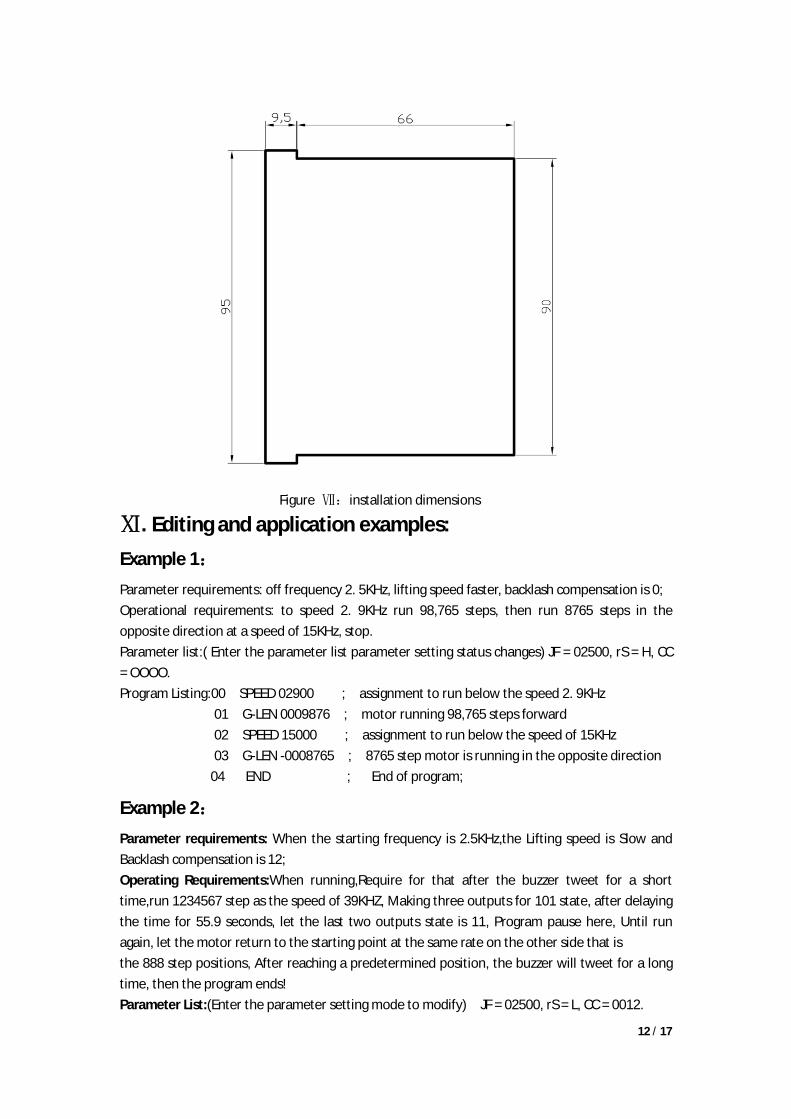
Ⅹ. Installation dimensions The controller uses the embedded instrument shell, small size and light weight (500g), recite the front panel is 71mm*71mm, length of 105mm, specific dimensions shown below:
Display Corresponding state Description
Step number (coordinates) display, To be run in automatic mode
When the actual coordinate values displayed over six digits (including the sign bit), only Show the last six digits
Counter display, To be run in automatic mode
When the value of the counter more than six digits, only Show the last six digits
Program display, To be run in automatic mode
The last six digits of the display, in order to express simple current program with six-figure line, we used 3,4-bit display the current line number: Bit 5 Empty: The first instruction is referred to as 6,7,8-bit display (refer to " directive search form " directive abbreviation)
Steps number, counting, program three display mode automatic operation
When the three display mode in the automatic operation display the first
two are the same, scilicet means the program under way.
Steps number, counting, program three display mode Automatic stop state
When the current two digits flashing,
it means that the program is interrupted, the breakpoint is waiting.
12 / 17
Figure Ⅶ:installation dimensions
Ⅺ. Editing and application examples: Example 1: Parameter requirements: off frequency 2. 5KHz, lifting speed faster, backlash compensation is 0; Operational requirements: to speed 2. 9KHz run 98,765 steps, then run 8765 steps in the opposite direction at a speed of 15KHz, stop. Parameter list:( Enter the parameter list parameter setting status changes) JF = 02500, rS = H, CC = OOOO. Program Listing:00 SPEED 02900 ; assignment to run below the speed 2. 9KHz 01 G-LEN 0009876 ; motor running 98,765 steps forward 02 SPEED 15000 ; assignment to run below the speed of 15KHz 03 G-LEN -0008765 ; 8765 step motor is running in the opposite direction
04 END ; End of program;
Example 2: Parameter requirements: When the starting frequency is 2.5KHz,the Lifting speed is Slow and Backlash compensation is 12; Operating Requirements:When running,Require for that after the buzzer tweet for a short time,run 1234567 step as the speed of 39KHZ, Making three outputs for 101 state, after delaying the time for 55.9 seconds, let the last two outputs state is 11, Program pause here, Until run again, let the motor return to the starting point at the same rate on the other side that is the 888 step positions, After reaching a predetermined position, the buzzer will tweet for a long time, then the program ends! Parameter List:(Enter the parameter setting mode to modify) JF = 02500, rS = L, CC = 0012.

13 / 17
Program Listing :( enter the program edit state) 00 OUT nnn0 ; Let the buzzer tweet for a short time 01 SPEED 39000 ; Assign the speed as 39KHz 02 G-LEN 01234567 ; Motor runs forward 1234567 step 03 OUT 101n ; Making three outputs for 101 state 04 DELAY 0055900 ; delaying the time for 55.9 seconds 05 OUT n11n ; let the last two outputs state is 11 06 PAUSE ; Program pause here 07 GOTO -0000888 ; let the motor return to the starting point on the other side that is the 888 step positions 08 OUT nnn1 ; Let the buzzer tweet for a long time 09 END ; the program ends!
Example 3: Operating Requirements: (Ignore the parameter setting) One object, from zero that run for 2.9KHz speed to run forward 100 step (this point as the reference point of the object); After the reference point stopped, the output is 010; Detect the input, if INI = 0, the motor will return to zero at the same speed. If INI ≠ 0, the motor will run forward 10,000 steps at a speed of 15KHz and let buzzer alarm for a short time; And then will return to the reference point at a speed of 35KHz. If INI = 0, then return to zero, Otherwise, continue to follow the way of the first to run.After return to zero ,The buzzer will alarm for a long time. Program Listing :( enter the program edit state) 00 SPEED 02900 ;Assign the speed as 2.9KHz 01 G-LEN 00000100 ;Motor runs forward 100 steps 02 OUT 010n ; Let output state is 010 03 J-BIT 11 1 0 ; 04 SPEED 15000 ; IN1 ≠ 0, then assign the new speed as 15KHz 05 G-LEN 00010000 ; Motor runs forward 10000 steps again 06 OUT nnn0 ; Let buzzer alarm for a short time 07 SPEED 35000 ; Assign the speed as 35KHz, For setting the speed of returning to the reference point 08 GOTO 00000100 ; Motor return to the reference point at the speed of 15KHz 09 LOOP 03 00000 ; Motor will run for an infinite loop ,until IN1 = 0, it will return to zero 10 SPEED 02900 ; Assign the speed of returning to zero as 2.9KHz 11 GOTO 00000000 ; Motor returns to zero at the of speed 2.9KHz 12 OUT nnn1 ; After return to zero ,The buzzer will alarm for a long time 13 END ; the program ends!
Example 4: Operating Requirements: (Ignore the parameter setting) One object, from zero that run for a high speed to run forward Until it came to the front of the limit switch, Then return to zero at the same rate, the program ends. (Assume the system beginning frequency is 500Hz, the distance

14 / 17
from the zero to proximity switch is greater than 100 000 steps, less than 100010 steps). Design analysis: the variable displacement of this movement does not know its precise value, but only know it's a general range (belong to a unknown variable). We use a method for interrupting operation to solve this problem. We connect the limit switch to the A operating port, Due the interrupt operation,the motor will slow down to stop, If run to the limit switch as a high-speed directly,will produce overshoot, In order to avoid the overshoot, we use this method that the first run as a high-speed ,then run as a low-speed (low-speed is below the starting frequency). Parameter List:(Enter the parameter setting mode to modify) Setting A Operator address nA = 04, other parameters are ignored. Program Listing :( enter the program edit state) 00 SPEED 39000 ; assign the speed as 39KHz 01 G-LEN 0099000 ; First, high-speed close to, but can’t hit the limit switch 02 SPEED 00400 ; low-speed frequency must below the starting frequency 03 G-LEN 07999999 ; The amount of displacement is set to the maximum, to reach the limit switch 04 SPEED 39000 ; A Operator, assign the return to zero speed as 39KHz 05 GO-AB -A ; In the opposite direction, running the same amount of displacement,back to zero 06 END; the program ends!
Ⅻ. directive search form NO.
Directive Name
Example Instructions, data range, unit Directive full name
Directive abbreviation
1 pause directive
00 PAUSE Program pauses, waiting for the start signal PAUSE PAU
2 displacement directive
01 G-LEN -1234567
According to the latest SPEED assignment speed, reverse mobile 1234567 step; pulses number
G-LEN G-L
3 Speed assignment directive
02 SPEED 12345
Run this directive following assignment speed; 12345Hz 1-39999, pulses / sec (Hz)
SPEED SPD
4 Delay directive
03 DELAY 1234567
Delay time: 1234567 ms 1-7999999, ms DELAY OLY
5 Unconditional jump directive
04 JUMP 12
Unconditional jump to the line XII program runs 00-99, line number
JUMP
JMP
6 Cycle directive
05 LOOP 03 12345
Jump from the current line to the (05) to 03 lines for 12,345 cycles 1-99999 (0 defined as infinite), Times (only forward loop)
LOOP
LOP
7 Move to a position
06 GOTO -1234567
Control the motor running to coordinate the position of -7999999- + is -1,234,567 7,999,999, the number of pulses (0 equivalent return to zero)
GOTO GOT
8 Output directive
07 OUT 03 01 N 0
Switch output is: 0UT = (K 0UT2 = 1,0UT3 unchanged internal buzzer a short sound (a = long beep, N = no sound)
OUT
OUT

15 / 17
ⅩⅢ. Parameters search form
9 Positioning Jump
08 J-BiT 19 2 0
If IN2 = 0, then 1.2 = Line number which jumps to line 19 execution data, 5 = input port, 8 = Jump status
J-BIT J-B
1 0 Counting Jump
09 J-CNT 20 12345
If the counter value> 12345, then jump to 20-line program execution 0-59999, natural number
J-CNT J-C
1 1 Variable displacement
09 GO-AB -A
If the motor is running: the absolute value of the displacement amount of A, A opposite to the direction and the soil A, ± B, the number of pulses (Note: A, B itself as a symbol number)
Go-rb GRB
12 Counter Is incremented 1
11 GNT-1 Value of the counter is incremented by 1 (Max count up to 999999)
CNE-I
CNI
13 Counter is cleared
12 GNT-O Counter is cleared CNE-O
CNO
14 Coordinate cleared
13 CLR Current coordinates and displays are cleared, the motor this location as a new zero
CLR
CLR
15 End of directive
13 END End of program lines, the directive can’t be edited, it always located at the last line.
END
END
NO.
Name example Data range
unit Parameter Description
1 Off frequency
JF12345 400-39999
Hz According to motor size and load inertia, etc. to choose parameters
JF
2 Rising and falling curve
rS H L,H Strip L slower; H faster (optimized design) RS
3 Backlash compensation
CC1234 0 -9999 Pluse number
Backlash compensation transmission mechanism
CC
4 Manual increment
HH 23456 1-999999 Pluse number
When the manual mode, the amount of displacement of the stepper motor
HL
5 Manual speed
HF12345 1-39999 Hz When the manual mode, the stepper motor speed
HF
6 Back to zero speed
bF12345 1-39999 Hz When return to zero operation ,running speed of the stepping motor
BF
7 "A Operation" entry
nA 18 00-99 Line number
A operation is interrupted, the program's entry address
NA
8 "B Operation" entry
nB 18 00-99 Line number
B operation is interrupted, the program's entry address
NB
9 Pulse mode CP 0 0、 1 CP = O single pulse, CP = I double pulse CP

16 / 17
ⅩⅣ. Button search form Button Function Instruction Use of state Use
method
run Start the program runs; startup program continues to run
Auto waiting to run status; run automatically stopped state; When executing directive pause
Click
enter Confirm the modification of the parameters are valid; Confirm the changes or enter the program effective
Parameter setting state; program edit state
Click
Pause Pause program is run automatically; pause the program is being run
Automatic operation; manual operation status
Click
cancel Cancel modified parameters; Cancel modify or entry process
Parameter setting state; program edit status
Click
home let motor return to zero (position when power is on)
Auto waiting to run status; The automatic operation stop status;
Click
Clear Clear all entered program;
Program edit status; Click for 2 seconds or more
delete Delete the current line program
Program edit status; Click
Auto Converted to automatic status:
manual status; Click
Jog Converted to manual status:
automatic status; Click
Insert Position in the program above the current row insert a new row program
Program edit status; Click
Step Displays the status switches to coordinate (steps) display
Auto waiting to run status Click
count Displays the status switch to count display mode
Auto waiting to run status Click
Program Displays the status switch to program display mode
Auto waiting to run status Click
edit Enter the program edit status
manual status; Click
set Enter the parameter setting status
manual status; Click for 2 seconds or more
quit From the program edit state or parameter setting state return to manual mode, and save the file to save the modified program or parameters
Program edit status; parameter setting status
Click
Move cursor to left
Current position move to the left
Program edit status; parameter setting status
Click
Quick View
Return after browsing program, only the line number and program name, as this program to see the data, click this
Program edit status Click
Move cursor to down
Current position move down one line
Program edit status; parameter setting status
Click

17 / 17
Counter is cleared
The current counter value is cleared
Auto waiting to run status
Move cursor to right
Current position move to the right
Program edit status; parameter setting status
Click
Counter save
Save the current counter value
Auto waiting to run status Click
reset Reset Controller Click