St Petersburg April 2011 Introduction to The Design …...St Petersburg April 2011 EUROCODES...
118
St Petersburg April 2011 EUROCODES Bridges: Background and applications 1 Introduction to The Design Example and EN 1990 - Basis of Design Professor Steve Denton Engineering Director, Parsons Brinckerhoff Visiting Professor, University of Bath Convenor, CEN/TC250 Horizontal Group - Bridges
Transcript of St Petersburg April 2011 Introduction to The Design …...St Petersburg April 2011 EUROCODES...
St Petersburg April 2011
EUROCODES Bridges: Background and applications
1
Introduction to The Design Example
and EN 1990 - Basis of Design
Professor Steve Denton Engineering Director, Parsons Brinckerhoff
Visiting Professor, University of Bath
Convenor, CEN/TC250 Horizontal Group - Bridges

St Petersburg April 2011 2
• Introduction
• Acknowledgements
• Introduction to the design example
• Overview of EN 1990, Basis of Design
Agenda

St Petersburg April 2011 3
• Introduction
• Acknowledgements
• Introduction to the design example
• Overview of EN 1990, Basis of Design
Agenda

St Petersburg April 2011 4

St Petersburg April 2011 5
Approach and Structure
EN 1990 Eurocode: Basis of structural design
EN 1991 Eurocode 1: Actions on structures
EN 1992 Eurocode 2: Design of concrete structures
EN 1993 Eurocode 3: Design of steel structures
EN 1994 Eurocode 4: Design of composite structures
EN 1995 Eurocode 5: Design of timber structures
EN 1996 Eurocode 6: Design of masonry structures
EN 1997 Eurocode 7: Geotechnical design
EN 1998 Eurocode 8: Design for earthquake resistance
EN 1999 Eurocode 9: Design of aluminium structures
St Petersburg April 2011 6
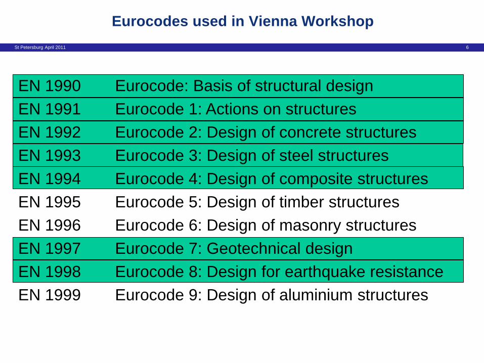
Eurocodes used in Vienna Workshop
EN 1990 Eurocode: Basis of structural design
EN 1991 Eurocode 1: Actions on structures
EN 1992 Eurocode 2: Design of concrete structures
EN 1993 Eurocode 3: Design of steel structures
EN 1994 Eurocode 4: Design of composite structures
EN 1995 Eurocode 5: Design of timber structures
EN 1996 Eurocode 6: Design of masonry structures
EN 1997 Eurocode 7: Geotechnical design
EN 1998 Eurocode 8: Design for earthquake resistance
EN 1999 Eurocode 9: Design of aluminium structures

St Petersburg April 2011 7
Eurocodes considered here
EN 1990 Eurocode: Basis of structural design
EN 1991 Eurocode 1: Actions on structures
EN 1992 Eurocode 2: Design of concrete structures
EN 1993 Eurocode 3: Design of steel structures
EN 1994 Eurocode 4: Design of composite structures
EN 1995 Eurocode 5: Design of timber structures
EN 1996 Eurocode 6: Design of masonry structures
EN 1997 Eurocode 7: Geotechnical design
EN 1998 Eurocode 8: Design for earthquake resistance
EN 1999 Eurocode 9: Design of aluminium structures

St Petersburg April 2011 8
• Introduction
• Acknowledgements
• Introduction to the design example
• Overview of EN 1990, Basis of Design
Agenda

St Petersburg April 2011 9
• European Commission and JRC
• Members of HG-Bridges
• Session presenters
• Vienna workshop report authors: • Y. Bouassida, E. Bouchon, P. Crespo, P. Croce, L. Davaine,
S. Denton, M. Feldmann, R. Frank, G. Hanswille, W. Hensen,
B. Kolias, N. Malakatas, G. Mancini, M. Ortega, J. Raoul,
G. Sedlacek, G. Tsionis
Acknowledgements

St Petersburg April 2011 10
• Introduction
• Acknowledgements
• Introduction to the design example
• Overview of EN 1990, Basis of Design
Agenda

St Petersburg April 2011 11
Introduction to design examples
Main example

St Petersburg April 2011 12
Introduction to design examples
Main example
EC1 EC7 EC4 EC3 EC2 EC8

St Petersburg April 2011 13
Introduction to design examples
Main example
EC1 EC7 EC4 EC3 EC2 EC8

St Petersburg April 2011 14
Introduction to design examples
Partial alternative examples
EC2 EC4

St Petersburg April 2011 15
Introduction to design examples
Partial alternative examples
EC1 EC2

St Petersburg April 2011 16
Introduction to design examples
Partial alternative examples
EC8
St Petersburg April 2011 17
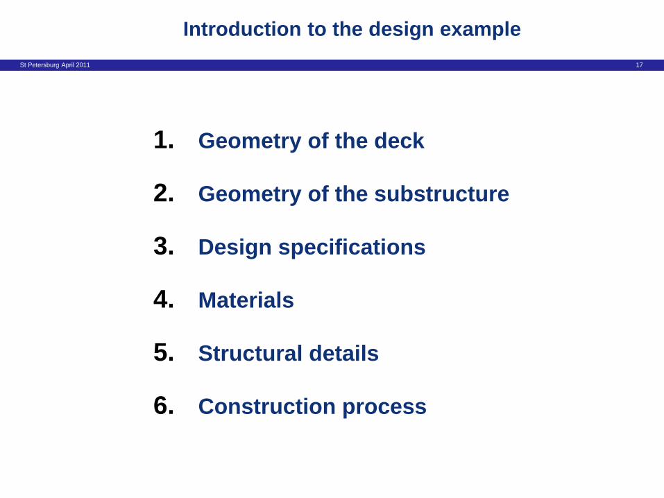
Introduction to the design example
1. Geometry of the deck
2. Geometry of the substructure
3. Design specifications
4. Materials
5. Structural details
6. Construction process
St Petersburg April 2011 18
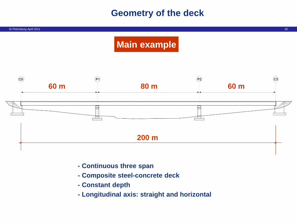
Geometry of the deck
Main example
200 m
80 m 60 m 60 m
- Continuous three span
- Composite steel-concrete deck
- Constant depth
- Longitudinal axis: straight and horizontal

St Petersburg April 2011 19
Geometry of the deck
12 m
Main example
Two girder composite deck
3.3 m
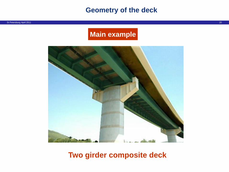
St Petersburg April 2011 20
Geometry of the deck
Main example
Two girder composite deck

St Petersburg April 2011 21
Geometry of the substructure
Piers
Squat pier case
H = 10 m
H = 40 m
High pier case

St Petersburg April 2011 22
Geometry of the substructure
10,0 m
Piers (I)
Squat pier case

St Petersburg April 2011 23
Geometry of the substructure
Piers (II)
High pier case
A A Section A-A
0.40 m

St Petersburg April 2011 24
Geometry of the substructure
Abutments

St Petersburg April 2011 25
Design specifications
- Design working life: 100 years
· Assessment of some actions (wind, temperature)
· Minimum cover requirements for durability
· Fatigue verifications

St Petersburg April 2011 26
Design specifications
- Non-structural elements
- Design working life: 100 years
· Parapets + cornices
· Waterproofing layer (3cm)
· Asphalt layer (8cm)

St Petersburg April 2011 27
Design specifications
- Traffic data
- Non-structural elements
- Design working life: 100 years
· Two traffic lanes (3.5m)
· Two hard strips (2.0m)
· LM1: Qi = qi = qr = 1.0
· No abnormal vehicles
For fatigue verifications:
· Two slow lanes (same position as actual lanes)
· Vehicle centrally placed on the lane
· Slow lane close to the parapet
· Medium flow rate of lorries
For assessment of general action effects
For assessment of transverse reinforcement
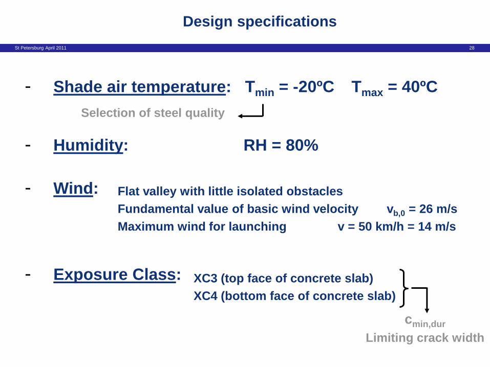
St Petersburg April 2011 28
- Humidity: RH = 80%
- Wind:
- Exposure Class:
Design specifications
Flat valley with little isolated obstacles
Fundamental value of basic wind velocity vb,0 = 26 m/s
Maximum wind for launching v = 50 km/h = 14 m/s
XC3 (top face of concrete slab)
XC4 (bottom face of concrete slab)
cmin,dur
Limiting crack width
- Shade air temperature: Tmin = -20ºC Tmax = 40ºC
Selection of steel quality

St Petersburg April 2011 29
- Soil conditions:
Design specifications
No deep foundation is needed
Settlement P1: 30 mm

St Petersburg April 2011 30
a) Structural steel
b) Concrete C35/45
c) Reinforcing steel Class B high bond bars fsk=500 MPa
d) Shear connectors S235J2G3 fu=450 MPa
Materials
Thickness Subgrade
t 30 mm S 355 K2
30 t 80 mm S 355 N
80 t 135 mm S 355 NL

St Petersburg April 2011 33
Construction process
- Launching of the steel girders
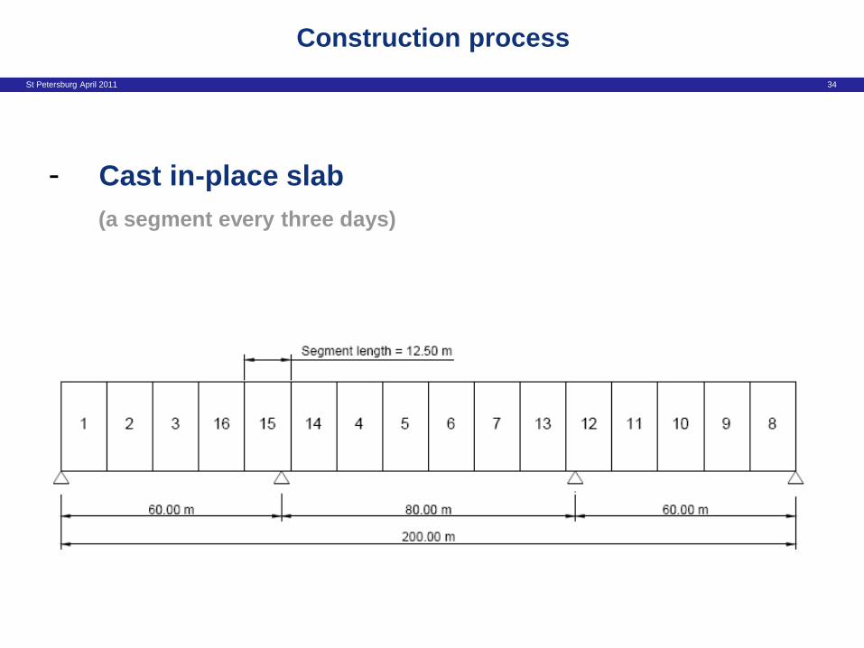
St Petersburg April 2011 34
Construction process
- Cast in-place slab
- (a segment every three days) (a segment every three days)

St Petersburg April 2011 35
Construction process
- Cast in-place slab

St Petersburg April 2011 36
Construction process
- Cast in-place slab

St Petersburg April 2011 37
Construction process
- Cast in-place slab

St Petersburg April 2011 38
Construction process
- Cast in-place slab
St Petersburg April 2011 39
• Introduction
• Acknowledgements
• Introduction to the design example
• Overview of EN 1990 - Basis of Design
Agenda

St Petersburg April 2011 40
Overview of EN 1990 – Basis of Design
1. General overview of EN 1990
2. Verification of limit states and
the combinations of actions

St Petersburg April 2011 41
Overview of EN 1990 – Basis of Design
1. General overview of EN 1990
2. Verification of limit states and
the combinations of actions

St Petersburg April 2011 42
EN1990 – Basis of Design: Contents
1 General 2 Requirements 3 Principles of Limit State Design 4 Basic Variables 5 Structural Analysis and Design Assisted by Testing 6 Verifications by the Partial Factor Method
Annexes

St Petersburg April 2011 43
EN1990 – Basis of Design Contents
Annex A1 Application for Buildings Annex A2 Application for Bridges Annex An Application for other structure types Annex B Management of Structural Reliability for Construction Works Annex C Basis for Partial Factor Design and Reliability Analysis Annex D Design Assisted by Testing

St Petersburg April 2011 44
• Provides principles and requirements for designers
• Establishes overall framework, tools and principles used by
drafters of the other Eurocode parts
Some of the EN1990 requirements are very general – specific
approaches to satisfying them are often contained in other Eurocode
parts, e.g.
Role of EN1990

St Petersburg April 2011 45
• Scope [1.1]
• Assumptions [1.3]
• Terms and definitions [1.5]
• Symbols [1.6]
EN1990: Section 1 - General

St Petersburg April 2011 46
Scope

St Petersburg April 2011 47
Some Important Assumptions

St Petersburg April 2011 48
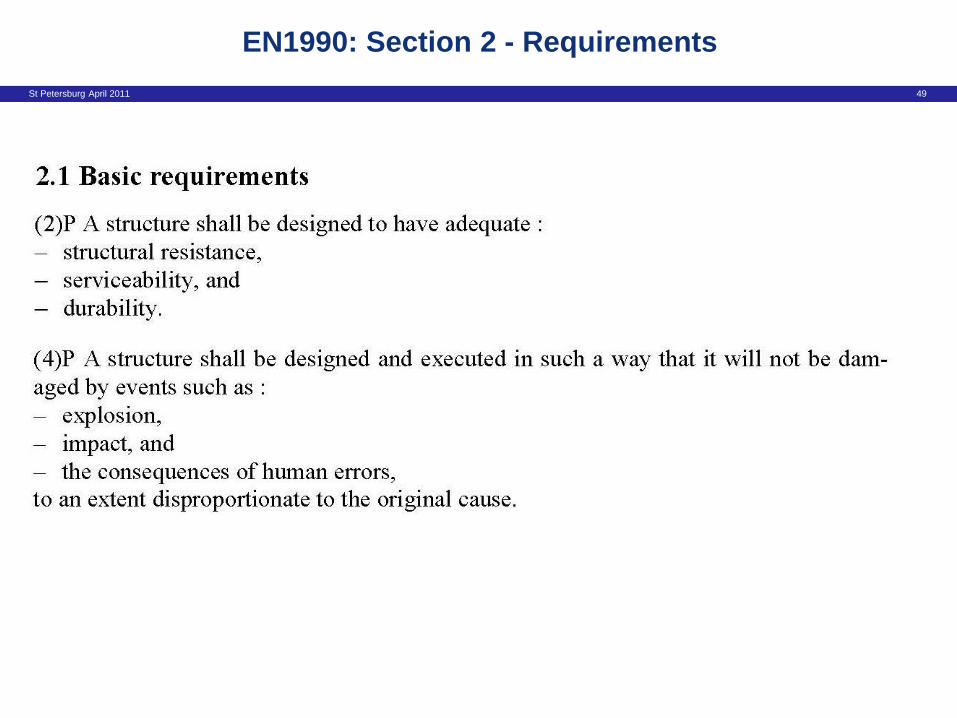
• Basic requirements [2.1]
• Design working life [2.3]
EN1990: Section 2 - Requirements
St Petersburg April 2011 49
EN1990: Section 2 - Requirements

St Petersburg April 2011 50
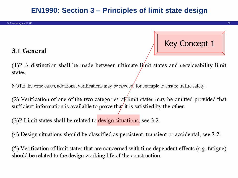
• General [3.1]
• Design situation [3.2]
• Ultimate limit states [3.3]
• Serviceability limit states [3.4]
• Limit state design [3.5]
EN1990: Section 3 – Principles of limit state design

St Petersburg April 2011 51
EN1990: Section 3 – Principles of limit state design
St Petersburg April 2011 52
EN1990: Section 3 – Principles of limit state design
Key Concept 1

St Petersburg April 2011 53
Key Concept 1 – Design Situations
• Design situations are categorised as persistent, transient,
accidental or seismic.
• These categorisations draw together families of circumstances or
conditions that the structure might experience during its life:
• Persistent design situations refer to conditions of normal use. As such, for
a highway bridge, they will include the passage of heavy vehicles since the
ability to carry heavy vehicles is a key functional requirement.
• Transient design situations refer to circumstances when the structure is
itself in some temporary configuration, such as during execution or repair.
• Accidental design situations refer to exceptional circumstances when a
structure is experiencing an extreme accidental event.
• Seismic design situations concern conditions applicable to the structure
when subjected to seismic events

St Petersburg April 2011 54
EN1990: Section 3 – Principles of limit state design

St Petersburg April 2011 55
EN1990: Section 3 – Principles of limit state design

St Petersburg April 2011 56
EN1990: Section 3 – Principles of limit state design
Key Concept 2

St Petersburg April 2011 57
• The Eurocodes differentiate between reversible and irreversible
serviceability limit states.
• Irreversible serviceability limit states are of greater concern than
reversible serviceability limit states.
• The acceptable probability of an irreversible serviceability limit state being
exceeded is lower than that for a reversible serviceability limit state.
• As will be seen later, a more onerous combination of actions is used for
irreversible serviceability limit states than reversible serviceability limit
states.
Key Concept 2 – Reversible and
Irreversible Serviceability Limit States

St Petersburg April 2011 58
• Actions and environmental influences [4.1]
• Material and product properties [4.2]
• Geometric data [4.3]
EN1990: Section 4 – Basic variables

St Petersburg April 2011 59
EN1990: Section 4 – Basic variables

St Petersburg April 2011 60
• EN1990 established four representative values of a
variable action
Characteristic Value (Qk) [1.5.3.14]
Combinations Value of a Variable Action (0Qk) [1.5.3.16]
Frequent Value of a Variable Action (1Qk) [1.5.3.17]
Quasi-permanent Value of a Variable Action (2Qk) [1.5.3.18]
Representative values of variable actions
Key Concept 3

St Petersburg April 2011 61
Representative Values of a Variable Action
Characteristic value Qk
Combination value oQk
Frequent value 1Qk
Quasi-permanent value 2Qk
Time
Instantaneous value of Q
t2 t1 t3

St Petersburg April 2011 62
• There are four different representative values of a Variable Action.
• The characteristic value is a statistically extreme value. It is the main
representative value, and the value generally defined in EN1991.
• The other representative values are called the combination value,
frequent value and quasi-permanent value. They are determined by
multiplying the characteristic value by 0 ,1 and 2 respectively.
• The combination, frequent and quasi-permanent values are less
statistically extreme than the characteristic value, so 0 ,1 and 2 are
always less than 1.
Key Concept 3 – Representative values of variable actions

St Petersburg April 2011 63
Material Properties

St Petersburg April 2011 64
EN1990: Section 5 – Structural analysis and
design assisted by testing

St Petersburg April 2011 65
• Key section – will return to it further later
• Design values [6.3] Actions, materials, geometric data, (effects of actions, resistances)
• Ultimate limit states [6.4] ULS’s to be verified, verification rules, combination rules
• Serviceability limit states [6.5] Verification rules, combinations of actions
EN1990: Section 6 – Verification by the partial factor method

St Petersburg April 2011 66
Ultimate Limit States
St Petersburg April 2011 67
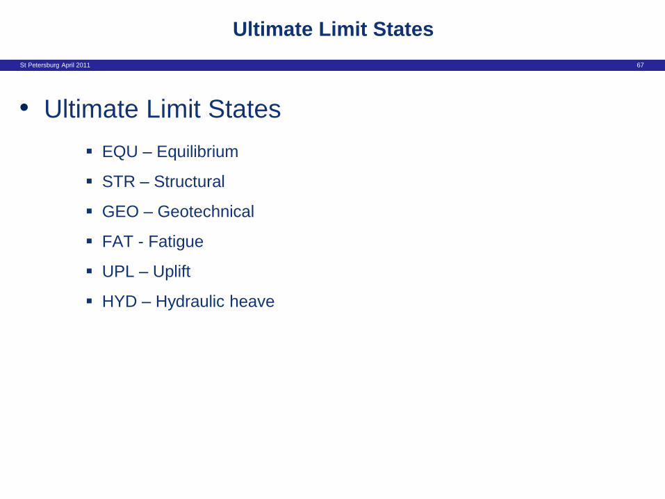
• Ultimate Limit States
EQU – Equilibrium
STR – Structural
GEO – Geotechnical
FAT - Fatigue
UPL – Uplift
HYD – Hydraulic heave
Ultimate Limit States

St Petersburg April 2011 68
• Ultimate Limit States
EQU – Equilibrium
STR – Structural
GEO – Geotechnical
FAT - Fatigue
UPL – Uplift
HYD – Hydraulic heave
Ultimate Limit States
Key Concept 4
St Petersburg April 2011 69
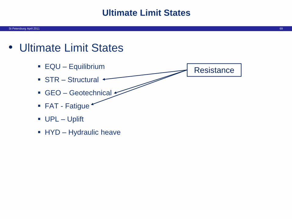
• Ultimate Limit States
EQU – Equilibrium
STR – Structural
GEO – Geotechnical
FAT - Fatigue
UPL – Uplift
HYD – Hydraulic heave
Ultimate Limit States
Resistance

St Petersburg April 2011 70
• Ultimate Limit States
EQU – Equilibrium
STR – Structural
GEO – Geotechnical
FAT - Fatigue
UPL – Uplift
HYD – Hydraulic heave
Ultimate Limit States
Resistance
Stability

St Petersburg April 2011 71
• Ultimate Limit States
EQU – Equilibrium
STR – Structural
GEO – Geotechnical
FAT - Fatigue
UPL – Uplift
HYD – Hydraulic heave
Ultimate Limit States
Resistance
Stability
EN1997

St Petersburg April 2011 72
• The Eurocodes explicitly establish six different ultimate limit states.
• Two of these, UPL and HYD, are specific to EN1997.
• Two are concerned with resistances: STR when verifying structural
resistance and GEO when verifying the resistance of the ground.
• FAT is concerned with fatigue.
• EQU is principally concerned with ultimate limit states involving a loss of
overall equilibrium. However, it has an important relationship with the
single source principle (see Key Concept 5)
• Different partial factors on actions and geotechnical material
properties are used for different ultimate limit states
Key Concept 4 – Six different Ultimate Limit States

St Petersburg April 2011 73
• Another key section for bridge design
• Combinations of action [A2.2]
General, rules for different bridge types, values of factors
• Ultimate limit states [A2.3]
Design values, design approaches, partial factors on actions
• Serviceability limit states [A2.4]
Design values, deformation, vibrations
EN1990: Annex A2 – Application for bridges

St Petersburg April 2011 74
EN1990: Annex A2 – Application for bridges

St Petersburg April 2011 75
EN1990: Annex A2 – Application for bridges

St Petersburg April 2011 76
Partial factors on actions

St Petersburg April 2011 77
Partial factors on actions

St Petersburg April 2011 78
ULS Partial Factors – Set A - Bridges

St Petersburg April 2011 79
Partial factors on actions

St Petersburg April 2011 80
ULS Partial Factors – Set B - Bridges

St Petersburg April 2011 81
Design situations – cases where
geotechnical actions or resistance present

St Petersburg April 2011 82
ULS Partial Factors – Set C - Bridges

St Petersburg April 2011 83
Single Source Principle
EN 1990, Annex A2:
Key Concept 5

St Petersburg April 2011 84
Single Source Principle
NOTE 3 The characteristic values of all permanent actions from one
source are multiplied by gG,sup if the total resulting action effect is
unfavourable and gG,inf if the total resulting action effect is favourable. For
example, all actions originating from the self weight of the structure may
be considered as coming from one source; this also applies if different
materials are involved. See however A2.3.1(2)
Key Concept 5

St Petersburg April 2011 85
• Application of the single source principle allows a single partial factor to
be applied to the whole of an action arising from a single source.
• The value of the partial factor used depends on whether the resulting
action effect is favourable or unfavourable.
• EN1990 allows the single source principle to be used for STR and GEO
verifications.
• EQU addresses cases when minor variations in the magnitude or
spatial distribution of a permanent action from a single source is
significant.
Key Concept 5 – Single Source Principle
St Petersburg April 2011 86
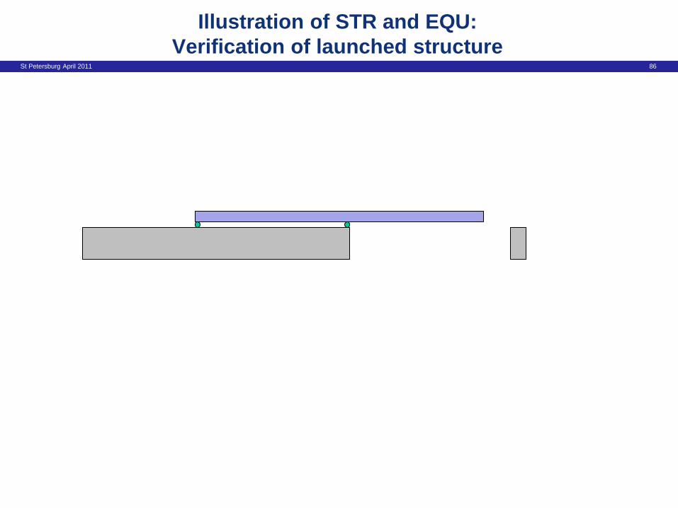
Illustration of STR and EQU:
Verification of launched structure

St Petersburg April 2011 87

St Petersburg April 2011 88
Illustration of STR and EQU:
Verification of launched structure
STR Verification : Moment over central support
Single source principle can be applied
EN1990 Set B Partial Factors used
gG,sup Gk,sup

St Petersburg April 2011 89

St Petersburg April 2011 90
Illustration of STR and EQU:
Verification of launched structure
EQU Verification
Single source principle not applied
EN1990 Set A Partial Factors used
gG,sup Gk,sup gG,inf Gk,inf

St Petersburg April 2011 91
Overview of EN 1990 – Basis of Design
1. General overview of EN 1990
2. Verification of limit states and
the combinations of actions

St Petersburg April 2011 92
Overview of EN 1990 – Basis of Design
1. General overview of EN 1990
2. Verification of limit states and
the combinations of actions
Key Concept 6
St Petersburg April 2011 93
Ultimate Limit States

St Petersburg April 2011 94
Verification (ULS)

St Petersburg April 2011 95
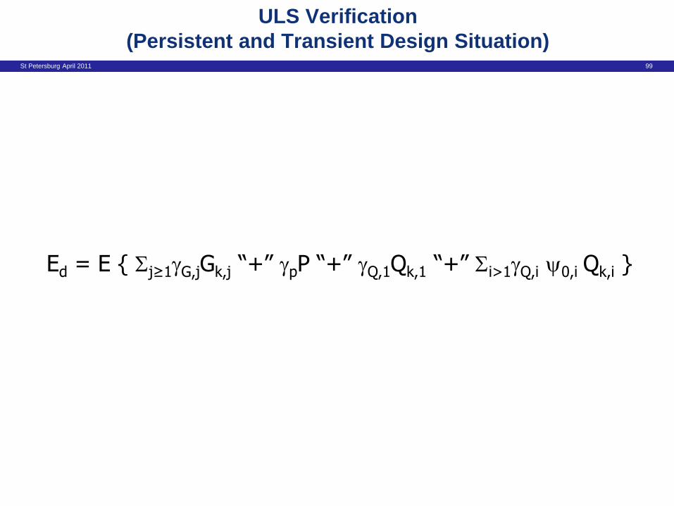
ULS Verification
(Persistent and Transient Design Situation)
Ed ≤ Rd

St Petersburg April 2011 96
Ed ≤ Rd
Applying Equation 6.10 from EN1990:
ULS Verification
(Persistent and Transient Design Situation)

St Petersburg April 2011 97
ULS Verification
(Persistent and Transient Design Situation)

St Petersburg April 2011 98
Ed = E { Sj≥1gG,jGk,j “+” gpP “+” gQ,1Qk,1 “+” Si>1gQ,i 0,i Qk,i }
Ed ≤ Rd
Applying Equation 6.10 from EN1990:
ULS Verification
(Persistent and Transient Design Situation)
St Petersburg April 2011 99
Ed = E { Sj≥1gG,jGk,j “+” gpP “+” gQ,1Qk,1 “+” Si>1gQ,i 0,i Qk,i }
ULS Verification
(Persistent and Transient Design Situation)

St Petersburg April 2011 100
ULS Verification
(Persistent and Transient Design Situation)
Ed = E { Sj≥1gG,jGk,j “+” gpP “+” gQ,1Qk,1 “+” Si>1gQ,i 0,i Qk,i }
Design effect
St Petersburg April 2011 101
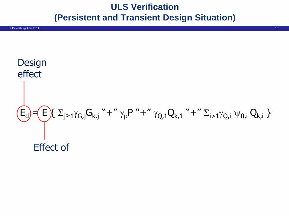
ULS Verification
(Persistent and Transient Design Situation)
Ed = E { Sj≥1gG,jGk,j “+” gpP “+” gQ,1Qk,1 “+” Si>1gQ,i 0,i Qk,i }
Design effect
Effect of

St Petersburg April 2011 102
ULS Verification
(Persistent and Transient Design Situation)
Ed = E { Sj≥1gG,jGk,j “+” gpP “+” gQ,1Qk,1 “+” Si>1gQ,i 0,i Qk,i }
Design effect
Effect of
Permanent actions

St Petersburg April 2011 103
ULS Verification
(Persistent and Transient Design Situation)
Ed = E { Sj≥1gG,jGk,j “+” gpP “+” gQ,1Qk,1 “+” Si>1gQ,i 0,i Qk,i }
Design effect
Effect of
Permanent actions
Combined with

St Petersburg April 2011 104
ULS Verification
(Persistent and Transient Design Situation)
Ed = E { Sj≥1gG,jGk,j “+” gpP “+” gQ,1Qk,1 “+” Si>1gQ,i 0,i Qk,i }
Design effect
Effect of
Permanent actions
Prestress
Combined with

St Petersburg April 2011 105
ULS Verification
(Persistent and Transient Design Situation)
Ed = E { Sj≥1gG,jGk,j “+” gpP “+” gQ,1Qk,1 “+” Si>1gQ,i 0,i Qk,i }
Design effect
Effect of
Permanent actions
Prestress
Leading variable action
Combined with

St Petersburg April 2011 106
ULS Verification
(Persistent and Transient Design Situation)
Ed = E { Sj≥1gG,jGk,j “+” gpP “+” gQ,1Qk,1 “+” Si>1gQ,i 0,i Qk,i }
Design effect
Effect of
Permanent actions
Prestress
Leading variable action
Accompanying variable actions Combined
with

St Petersburg April 2011 107
factors for highway bridges

St Petersburg April 2011 108
Combinations of Actions – Treatment of variable actions
Combination also includes Ad
Notes:
(1) Values of gQ are obtained from tables A2.4(A) – (C) of EN 1990.
(2) Expression 6.11 allows the use of either or 1 or 2
(3) Guidance on which combination should be used for specific verifications is given in the relevant Parts of
EN 1992 to EN 1999 for SLS, and is dependent upon the design situation at ULS.
Leading Accompanying
gQ (1)
gQ (1)
ULS Persistent and Transient Design Situations gQ 1.0 gQ 0
ULS Accidental Design Situation 1.0 1 (2) 1.0 2
(SLS) Characteristic Combination 1.0 1.0 1.0 0
(SLS) Frequent combination 1.0 1 1.0 2
(SLS) Quasi permanent Combination (also used for long term effects)
1.0 2 1.0 2
or 2

St Petersburg April 2011 109
ULS Verification (Accidental Design Situation)
Ed = E { Sj≥1Gk,j “+” P “+” Ad “+” (1,1 or 2,1) Qk,1
“+” Si>12,i Qk,i }

St Petersburg April 2011 110
Combinations of Actions – Treatment of variable actions
Combination also includes Ad
Notes:
(1) Values of gQ are obtained from tables A2.4(A) – (C) of EN 1990.
(2) Expression 6.11 allows the use of either or 1 or 2
(3) Guidance on which combination should be used for specific verifications is given in the relevant Parts of
EN 1992 to EN 1999 for SLS, and is dependent upon the design situation at ULS.
Leading Accompanying
gQ (1)
gQ (1)
ULS Persistent and Transient Design Situations gQ 1.0 gQ 0
ULS Accidental Design Situation 1.0 1 (2) 1.0 2
(SLS) Characteristic Combination 1.0 1.0 1.0 0
(SLS) Frequent combination 1.0 1 1.0 2
(SLS) Quasi permanent Combination (also used for long term effects)
1.0 2 1.0 2
or 2

St Petersburg April 2011 111
Serviceability Limit States

St Petersburg April 2011 112
SLS Verification Combinations of Actions
Ed = E { Sj≥1Gk,j “+” P “+” Qk,1 “+” Si>10,i Qk,i }
Characteristic Combination – Normally used for irreversible limit states

St Petersburg April 2011 113
Example from EN1992-1-1

St Petersburg April 2011 114
Combinations of Actions – Treatment of variable actions
Combination also includes Ad
Notes:
(1) Values of gQ are obtained from tables A2.4(A) – (C) of EN 1990.
(2) Expression 6.11 allows the use of either or 1 or 2
(3) Guidance on which combination should be used for specific verifications is given in the relevant Parts of
EN 1992 to EN 1999 for SLS, and is dependent upon the design situation at ULS.
Leading Accompanying
gQ (1)
gQ (1)
ULS Persistent and Transient Design Situations gQ 1.0 gQ 0
ULS Accidental Design Situation 1.0 1 (2) 1.0 2
(SLS) Characteristic Combination 1.0 1.0 1.0 0
(SLS) Frequent combination 1.0 1 1.0 2
(SLS) Quasi permanent Combination (also used for long term effects)
1.0 2 1.0 2
or 2

St Petersburg April 2011 115
SLS Verification Combinations of Actions
Ed = E { Sj≥1Gk,j “+” P “+” 1,1 Qk,1 “+” Si>12,i Qk,i }
Frequent Combination – Normally used for reversible limit states
St Petersburg April 2011 116
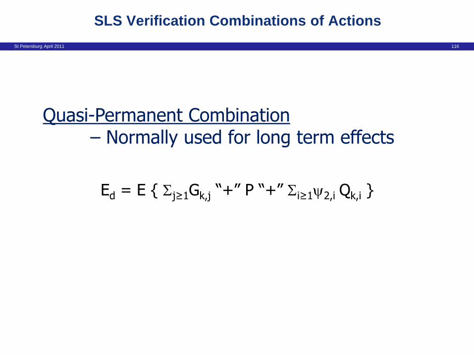
SLS Verification Combinations of Actions
Ed = E { Sj≥1Gk,j “+” P “+” Si≥12,i Qk,i }
Quasi-Permanent Combination – Normally used for long term effects
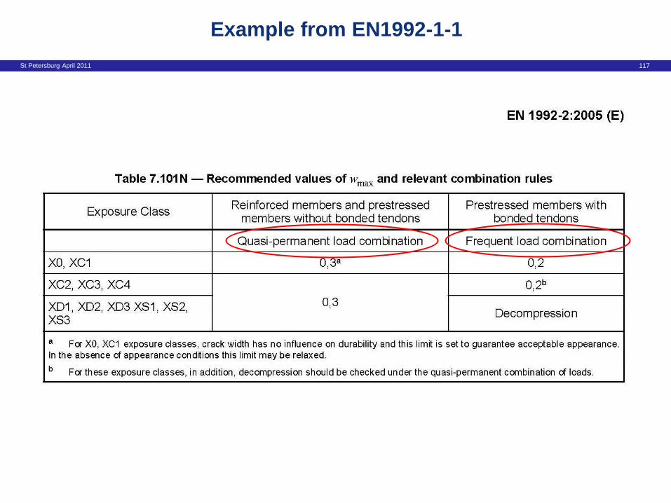
St Petersburg April 2011 117
Example from EN1992-1-1
St Petersburg April 2011 118
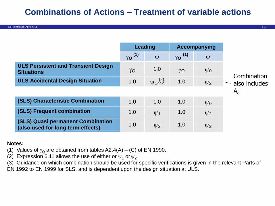
Combinations of Actions – Treatment of variable actions
Combination also includes Ad
Notes:
(1) Values of gQ are obtained from tables A2.4(A) – (C) of EN 1990.
(2) Expression 6.11 allows the use of either or 1 or 2
(3) Guidance on which combination should be used for specific verifications is given in the relevant Parts of
EN 1992 to EN 1999 for SLS, and is dependent upon the design situation at ULS.
Leading Accompanying
gQ (1)
gQ (1)
ULS Persistent and Transient Design Situations gQ 1.0 gQ 0
ULS Accidental Design Situation 1.0 1 (2) 1.0 2
(SLS) Characteristic Combination 1.0 1.0 1.0 0
(SLS) Frequent combination 1.0 1 1.0 2
(SLS) Quasi permanent Combination (also used for long term effects)
1.0 2 1.0 2
or 2

St Petersburg April 2011 119
• EN1990 establishes five different combinations of actions.
• Different combinations of actions are used for verifying different
limit states. They have different statistical likelihoods of
occurring.
• The quasi-permanent combination is also used when analysing
long-term effects.
• The differences between the combinations of actions concern:
whether partial factors are applied; which representative values of
variable actions are used; and, whether there is an accidental
action included.
• The different combinations of actions are used in conjunction with
the Eurocode ‘material parts’. The Eurocode part generally states
explicitly which combination is to be used in each SLS verification.
Key Concept 6 – Five Combinations of Actions
St Petersburg April 2011 120
• Design situations
• Reversible and irreversible serviceability limit states
• Representative values of variable actions
• Six ultimate limit states
• Single source principle
• Five combinations of actions
Six key concepts of EN 1990 - summary