
ST 75 Systems - docs-emea.rs-online.com · extracção de fumos, como os Sistemas disponiveis na...
34
Operation & Maintenance Manual ST 75 Systems
Transcript of ST 75 Systems - docs-emea.rs-online.com · extracção de fumos, como os Sistemas disponiveis na...

Operation & Maintenance Manual
ST 75 Systems

TABLE OF CONTENTS
i
TITLE PAGE
General Information ..................................................................................................2Introduction ..................................................................................................2Specifications ................................................................................................3Parts Identification ........................................................................................4
Safety .......................................................................................................................5Safety Guidelines, English Language ............................................................5Safety Guidelines, French Language .............................................................6Safety Guidelines, German Language ............................................................7Safety Guidelines, Italian Language ..............................................................8Safety Guidelines, Portuguese Language ......................................................9Safety Guidelines, Spanish Language ......................................................... 10Safety Guidelines, Swedish Language ......................................................... 11
Set-Up .................................................................................................................... 12Tip & Tool Stand ......................................................................................... 12Handpiece Vacuum/Pressure ....................................................................... 13Handpiece Conntection ............................................................................... 14System Power Up ........................................................................................ 14Heater Burn In ............................................................................................. 15
Operation ............................................................................................................... 15Temperature Selection ................................................................................. 15LED Operation ............................................................................................. 16
Repair ..................................................................................................................... 17Repair Procedure ......................................................................................... 17Calibration ................................................................................................... 18Corrective Maintenance .............................................................................. 19
Power Source .................................................................................... 19Handpieces ....................................................................................... 20
Disassembly/Assembly ............................................................................... 21Assembly Detail .......................................................................................... 23Wiring Diagram............................................................................................ 24Schematic .................................................................................................... 25

ii
TABLE OF CONTENTS
Packing List/Spare Parts ......................................................................................... 28Packing List ................................................................................................. 28Spare Parts ................................................................................................... 29
Limited Warranty Registration ............................................................................... 30
TABLE PAGE
Table 1 Power Source ......................................................................................... 19Table 2 Heater Assembly Checkout Procedures ................................................. 20Table 3 Packing List ............................................................................................ 28Table 4 Spare Parts ............................................................................................. 29

© 2000 PACE Incorporated, Laurel MD. All rights reserved. Printed in the U.S.A.
PACE Incorporated retains the right to make changes to specificationscontained herein at any time, without notice.
Contact your local authorized PACE Distributor or PACE Incorporated toobtain the latest specifications.
The following are registered trademarks and/or servicemarks of PACEIncorporated, Laurel Maryland U.S.A. and may only be used to identifygenuine PACE products or services:
Arm-Evac, Mini-Wave, PACE, SensaTemp, Snap-Vac, Sodrtek, Sodr-X-Tractor, ThermoFlo, ThermoJet, ThermoTweez, Toolnet, Visifilter.
For any questions regarding this Operation & Maintenance Manual, contactyour local authorized PACE distributor or contact PACE directly at theappropriate address listed below.
PACE USA 9893 Brewers Court, Laurel, Maryland 20723-1990Tel. (888)535-7223 (toll-free), (301)490-9860FAX (301)483- 7030www.paceworldwide.com
PACE EUROPE Sherbourne House Sherbourne Drive TilbrookMilton Keynes United Kingdom MK7 8HXTel. (44)01908 277 666 FAX (44)01908 277 777
iii

1
MANUAL NUMBER 5050-0456REV. C

2
Introduction
Thank you for purchasing the PACE model ST 75 Soldering/Desoldering System.This manual will provide you with the information necessary to properly set up,operate and maintain the ST 75 system.
The ST 75 systems are available in either the 115 VAC, or 230 VAC version whichincorporates a highly responsive SensaTemp (closed loop) control system providingup to 80 Watts of total power to a single output channel. The 230 VAC versionsystem bears the CE Conformity Marking which assures the user that it conformsto all the requirements of council directive EMC 89/336/EEC. The systemspackage the power source with a selection of accessories and functional aids.
The PACE Sodr-X-Tractor handpiece provides thermally enhanced thru-holedesoldering, safe removal of TQFP (Thin Quad FlatPack) and TSOP (Thin SmallOutline Package) surface mount components and continuous removal of old solderfrom surface mount lands.
PACE SensaTemp handpieces may be used with the ST 75 system to perform a widevariety of advanced surface mount & thru-hole component removal/replacementoperations.
General Information

3
Specifications
System power sources are available in either the 115 VAC or 230 VAC version.The 230 volt system bears the Conformity Marking which assures the user that itconforms to all the requirements of (EU) directive EMC 89/336/EEC & 73/23/EEC.
System Power Source Power Requirements:
ST 75 - Operates on 97-127 VAC, 50/60Hz120 Watts maximum at 115 VAC, 60Hz
ST 75E - Operates on 197-253 VAC 50/60Hz120 Watts maximum at 230 VAC, 50Hz
Temperature Specifications:Tip Temperature Range: 204°C to 454°C (400°F to 850°F) nominal.Temperature Stability: ±1.1°C (±2°F) at idle from set tip temp.
Vacuum And Air:
(Measurements at front panel Vacuum and Controllable Pressure Ports.)
Vacuum Rise Time: 200 ms average as measured by PACEPPM 100 Process Monitor.
Vacuum: 51 cm Hg. (20 in. Hg.) (nominal)
Pressure: 1.44 Bar (21 P.S.I.) (nominal at MAX setting)
Air Flow: 6 SLPM (0.22 SCFM) maximum
EOS/ESD Specifications:
The specifications shown below apply except on "Soft Ground Systems" which havea 1 meg ohm current limiting resistance and a label placed on the power source frontpanel referring to EN 100015-1.
Tip-To-Ground Resistance: Less than 2 ohms.
AC Leakage: Less than 2 millivolts RMS from 50Hz to 10MHz.
Transient Level: Less than 500mV peak, out to 100MHz.
General Information
NOTE - Actual minimum and maximum Operating Tip Temperatures may varydepending on Handpiece, Tip selection and application.

4
Parts Identification
General Information
9 - Earth Ground Receptacle (230 VAC Systems only)
1 - Power Receptacle
2 - LED
3 - Variable Temperature Control
4 - Vacuum Port
5 - Controllable Pressure Port
6 - Power Switch
7/8 - AC Power Receptacle/FuseHolder

5
Safety Guidelines - English Language
The following are safety precautions which personnel must understand and followwhen using or servicing PACE products.
1. POTENTIAL SHOCK HAZARD - Repair procedures on PACE productsshould be performed by Qualified Service Personnel only. Line voltageparts may be exposed when the equipment is disassembled. Servicepersonnel must avoid contact with these parts when troubleshooting theproduct.
2. To prevent personnel injury, adhere to safety guidelines in accordancewith OSHA and other applicable safety standards.
3. SensaTemp handpiece heaters and installed tips are hot when thehandpiece is powered on. DO NOT touch either the heater or the tip.Severe burns may result.
4. PACE Tip & Tool Stands and handpiece cubbies are designed specificallyfor use with the associated handpiece and houses it in a manner whichprotects the user from accidental burns. Always store the handpiece in itsholder. Be sure to place the handpiece in its holder after use and allow tocool before storing.
5. Always use PACE systems in a well ventilated area. A fume extractionsystem such as those available from PACE are highly recommended tohelp protect personnel from solder flux fumes.
6. Exercise proper precautions when using chemicals (e.g., solder paste).Refer to the Material Safety Data Sheet (MSDS) supplied with eachchemical and adhere to all safety precautions recommended by themanufacturer.
Safety

6
Sécurité
Directives de Sécurité, Française Langue
Les précautions suivantes, sont celles que le personnel doit comprendre et suivrelorsqu'il utilise, effectue la maintenance ou se sert d'un produit PACE.
1. Danger potentiel de choc èlectrique - Les procédures de réparation surles produits PACE doivent être effectuées seulement par du personnelqualifié. Des parties de l'équipement désassemblées peuvent être soustension. Le personnel de maintenance doit éviter tout contact avec cesparties en réparant le produit.
2. Pour prévenir tout préjudice, le personnel adhère au guide de sécurité enaccord avec OSHA (équivalent à des normes françaises de sécurité) etd'autres standards de sécurité applicable.
3. La mise sous tension des outils SensaTemp comporte des élémentschauffants (buse). Ces derniers, gardent la chaleur même après la misehors tension pendant un certain temps. Ne pas toucher les partieschaudes aux extrémités des outils. Des brûlures sévères peuvent enrésulter.
4. Les outils PACE et leurs pannes ainsi que le support sont dessinés demanière spécifique afin de protéger l'utilisateur/opérateur de brûluresaccidentelles. Reposer toujours les outils après chaque utilisation dansleurs étuis/supports afin de permettre leur refroidissement.
5. Utiliser toujours les stations Pace dans unlieu bien ventilé. Desextracteurs de fumée Pace sont hautement recommandés pour protégervotre personnel des vapeurs de soudure/flux.
6. Prenez les mesures nécessaires quand vous utilisez des produits (ex:solder paste) chimiques. Reportez-vous au document (fiche technique/sécurité) du fabricant fourni avec chaque produit. Respectez toutes lesprocédures de sécurité recommandées par le constructeur.

7
Sicherheit
Sicherheit Korrekturlinien, Deutsche Sprache
Die nachfolgenden Sicherheitsvorschriften sollten vom Bedien- un Servicepersonalverstanden und befolgt werden.
1. Entladung spannungsfuehrender Teile - Reparaturen an PACE Produktensollten nur von qualifizierten Personal durchgefuehrt werden.Spannungsfuehrende Teile koennen sich bei gezogenen Netzsteckerentladen. Servicepersonal muss den Kontakt dieser Teile vermeiden.
2. Um moegliche Gefahren fuer Personen auszuschliessen, muessen alleSicherheitsvorschriften in Uebereinstimmung mit OSHA und anderenanwendbaren Sicherheitsstandards eingehalten werden.
3. Angeschlossene SensaTemp Heizelemente von Handwerkzeugen undinstallierte Loetspitzen sind heiss wenn das System eingeschaltet ist odererst vor kurzer Zeit ausgeschaltet wurde. Heizelement und Loetspitzenicht beruehren. Verbrennungsgefahr.
4. PACE Tip & Tool und andere Handwerkzeugablagen sind so konstruiert,dass ein versehentliches Beruehren des dazugehoerendesHandwerkzeuges vermieden wird. Bewahren Sie das Handwerkzeug nachGebrauch stets in der Ablage auf. Bevor das Handwerkzeug an einemanderen Ort gelagert werden muss, lassen Sie es in der Werkzeugablagevollstaendig abkuehlen.
5. Benutze PACE Systeme nur in gut beluefteten Raeumen. EinLoetrauchabsaugsystem, wie es z.B. von PACE erhaeltlich ist, hilftBedienpersonen von den Gefahren von Loetrauch zu schuetzen.
6. Wenn Chemikalien (z.B.: Lotpaste) verwendet werden, muessen alle die inden Sicherheitsdatenblaettern des Herstellers ausgewiesenenSicherheitsvorschriften eingehalten werden.

8
Sicurezza
Misure di Sicurezza, Italiana Lingua
Le seguenti instruzioni sono misure di sicurezza che il personale deve comprendere eseguire quando utilizza o ripara I prodotti PACE.
1. EVENTUALI RISCHI DI SHOCK ELETTRICO- Si consiglia di fareseguire le operazioni di riparazione dei prodotti PACE, da un servizio dipersonale qualificato. Quando la stazione non é assemblata le partisottoposte alla tensione di linea potrebbero essere scoperte. Il personaledeve evitare il contatto con queste parti durante manutenzione delprodotto.
2. Per evitare eventuali pericoli al personale, attenersi alle norme di sicurezzapreviste dalla guida, in conformitá all’OSHA e agli altri Standard di Sicurezzaapplicabili.
3. Le resistenze PACE Sensatemp e le punte installate sono calde quando lastazione é accesa e per un periodo successivo allo spegnimento. Nontoccare la resistenza e la punta. Puó comportare gravi ustioni.
4. I supporti PACE sono specificamente costruiti insieme alla corrispondenteimpugnatura e progettati per un uso che protegge gli utenti da ustioniaccidentali. Mettere sempre l’impugnatura nel propio supporto dopol’utilizzo e lasciarla raffredare prima di riporla.
5. Utilizzare sempre I stazioni PACE in una zona be aerata per proteggere ilpersonale dai fumi. É fortemente raccomandato un sistema di aspirazione(dei fumi) come quello disposta dalla PACE.
6. Usare precauzioni quando si utilizzano sotanze chimiche (es. Pasta distagno). Fare riferimento al Material Safety Data Sheet (MSDS) fornita conogni sostanza chimica e seguire tutte le misure di sicurezza raccomandatedal fabbricante.

9
Segurança
Guidelines de Segurança, Portuguese Lingua
Segeum-se precauções de segurança que os operadores devem compreender e seguirao utilizar ou reparar produtos PACE.
1. Perigo de choque eléctrico - Os procedimentos de reparação emprodutos PACE, devem ser apenas efectuados por pessoal qualificado.Linhas de alimentação podem ficar expostas ao desmontar oequipamento. Pessoal de reparação deve evitar o contacto com essaspartes ao reparar o produto.
2. Para evitar danos pessoais, siga as normas de segurança OSHA ououtras normas aplicáveis.
3. Resistencias de aquecimento dos ferros e as pontas instaladas estãoquentesquando o ferro está alimentado, e mesmo durante algum tempoapós ser desligado. NUNCA TOCAR nem na resistencia de aquecimentonem na ponta. Pode resultar em queimaduras severas.
4. Os suportes para pontas e ferros da PACE, foram concebidos para usoespecifico, e para proteger o operador de queimaduras acidentais.Coloque sempre os ferros nos respectivos suportes. Tenha a certeza decolocar sempre o ferro no respectivo suporte após cada utilização e deixe-o arrefecer antes de o guardar.
5. Utilize sempre os sistemas da PACE em locais bem ventilados. Um Sistema deextracção de fumos, como os Sistemas disponiveis na PACE, são altamenterecomendados para a protecção dos utilizadores contra os fumos produzidos pelasolda e fluxo.
6. Tenha precauções apropriadas ao utilizar produtos quimicos (ex. pasta de soldar).Lêr sempre atentamente os normas de segurança fornecidas com cada produtoquímico e siga sempre todas as precauções de segurança recomendadas pelofabricante.

10
Lo siguiente es precauciones de seguridad que el personal debe entender y debeseguir al usar o reparar productos de PACE.
1. RIESGO de SHOCK POTENCIAL - Los procedimientos de la Reparación enproductos de PACE sólo deben ser realizados por Personal de ServicioCalificado. Pueden exponerse partes de voltaje de línea cuando el equipo sedesmonta. El personal de servicio debe evitar contacto con estas partes alarreglar el producto.
2. Para prevenir lesión del personal, adhiera a las reglas de seguridad deacuerdo con OSHA y otras normas de seguridad aplicables.
3. Las herramientas SensaTemp tienen sus calentadores y las puntasinstaladas calientes cuando la herramienta esta encendida y por unperiodo de tiempo después de apagar el equipo. No toque el calentador ola punta. Las quemaduras severas pueden resultar.
4. El Soporte de punta y Herramienta PACE se diseñan específicamente parael uso con las herramientas asociadas y las almacena de una manera queprotege al usuario de las quemaduras accidentales. Siempre guarde laherramienta en su soporte. Esté seguro de poner la herramienta en susoporte después del uso y permita que la herramienta enfríe antes deguardar.
5. Siempre use sistemas de PACE en una área bien ventilada. Un sistema deextraccíon de humo como esos disponibles de PACE se recomiendan paraayudar a protejer al personal contra los humos de flujo de soldadura.
6. Ejercicie las precauciones apropiadas al usar químicos (ej., pasta de la soldadura).Refiérase a la Hoja de Datos de Seguridad de Material (MSDS) proporcionadó concada químico y adhiere a todas las precauciones de seguridad recomendadas porel fabricante.
Guias de Consulta de Seguridad, Espãnol Lenguaje
Seguridad

11
Säkerhetsföreskrifter
Följande säkerhetsföreskrifter måste förstås och följas av personal som använder ellerutför service på PACE produkter.
1. RISK FÖR STRÖMSTÖT - Service / Reparation av PACE produkter fårendast utföras av aktoriserad service personal. Strömförande delar kankommas åt när produkten är isärplockad. Iaktag aksamhet när felsökninggörs för att undvika strömstötar.
2. För att undvika personskada rekommenderas att OSHA eller andraliknande arbetssäkerhets standarder följs.
3. SensaTemp verktygselement och installerade spetsar är heta när strömmenär påslagen och en tid efter att strömmen slagits av. RÖR EJ element ellerspets. Risk för brännskador!
4. PACE Spets och Verktygshållare är speciellt utformade för att passa PACErespektive verktyg så att risken för brännskador kan undvikas. Närverktyget ej används bör det alltid förvaras i sin hållare.
5. Tillse att ventilationen är god där PACE System används. Ett lödröksutsugsystem som t.ex. PACE tillhandahåller rekommenderas för att skyddaanvändaren för giftig lödrök.
6. Tillse att gällande säkerhetsföreskrifter följs vid användning av kemikalier,t.ex. lodpasta.Se säkerhetsdatabladen som medföljer kemikalierna och följde rekommenderade säkerhetsföreskrifterna från respektive tillverkare.
Säkerhetsföreskrifter, Svenska

12
Tip & Tool Stand
If you have purchased a system with a handpiece, set up the Tip & Tool Stand in thefollowing manner. Set up any other SensaTemp handpiece, use the instructionsenclosed with the handpiece and associated Tip & Tool Stand.
Set-Up
1. Attach the stand to either side of the power source, in the following manner.
a) Insert the 2 large hex headMounting Screws (head first) intothe lower "T" slot on the side ofthe power source case as shown.
b) Place the Tip & Tool Stand inposition beside the power source.Insert ends of the 2 MountingScrews into the 2 Tip & ToolStand mounting holes shown.
c) Install a Thumb Nut onto the endof each Mounting Screw. TightenThumb Nuts to secure the standin position.
2. Place handpiece into Tip & Tool Stand.

13
Set-Up
Handpiece Vacuum/Pressure
To set up your Sodr-X-Tractor air hose connection, perform the following steps:
1. Air Hose To Handpiece Connectiona) Attach one end of a 137cm (54 inch) length of air hose to the metal tube in
the back of the handpiece.b) If you have a PACE system incorporating only one handpiece, attach the
air hose to the power cable using the supplied Hose Clamps. Space themevenly along the length of the power cable starting at a point 6 inches fromthe ends of the handpiece.
c) If you have a PACE system incorporating 2 or more air handpieces, youmay wish to leave the air hose assembly unattached to allow a quickchange to any air handpiece being used.
2. Prepare a VisiFilter in the following manner:a) Connect a 1 inch (2.5cm) length of clear pvc air
hose to the FLOW OUT side of the VisiFilter;push and turn the hose onto the VisiFilternipple to seat.
b) Insert the ribbed end of a male quick connecthose mount fitting (P/N 1259-0087) into the freeend of the 1 inch (2.5cm) length of air hoseconnected to the FLOW OUT side of theVisiFilter.
c) Connect the free end of the 137cm (54 inch)length of air hose to the FLOW IN side of theVisiFilter.
d) Insert the end of the quick connect hosemount fitting (on VisiFilter FLOW OUT side)into the power source Vacuum Port.
3. When using air pressure, and/or utilizing multipleair handpieces, PACE recommends the use of the following set up procedurewhich utilizes additional quick connect hose mount fittings. An assortment ofquick connect air fittings are supplied with each additional air handpiece.a) Disconnect the 137cm (54 inch) length of air hose from the FLOW IN side
of the VisiFilter assembly. Insert the ribbed end of a male quick connecthose mount fitting (P/N 1259-0087) into the free end of this air hose.

14
Set-Up
b) Connect the free end of a 1 inch (2.5cm) length of air hose with aninstalled female quick connect hose mount fitting (P/N 1259-0086) tothe FLOW IN side of the VisiFilter Assembly.
c) The 137cm (54 inch) length of air hose can now be easily movedbetween the VisiFilter Assembly and the Controllable Pressure Port.The VisiFilter assembly remains connected to the Vacuum Port.
4. Additional fittings may also be added to the hose connection at the rear ofeach air handpiece to ease changing of handpieces.
NOTE
When removing any air hose, turn and pull. Do not attempt to pull hose directly off.Damage to or breakage of fitting or VisiFilter may occur. Use your Sodr-X-Tractor witha clean VisiFilter element. Otherwise a deterioration in performance or damage to theunit may occur.
Handpiece Connection
Connect the handpiece connector plug intothe Power Receptacle in the following manner.
1. Align guide on connector with slot onpower receptacle.
2. Insert connector into power receptacle.
3. Turn the connector housing clockwiseto lock in place.
System Power Up
the rear panel of the power source.
2. Plug the prong end (male end) of the power cord into a 3 wire groundedAC supply receptacle. The system is now ready for operation.
CAUTIONTo insure operator safety, the AC supply receptacle must be checked for propergrounding before initial operation.
3. Read this manual and all other included manuals thoroughly beforeoperating the system.
1. Insert the female end of the power cord into the AC Power Receptacle at

15
Set-Up/Operation
Heater Burn In
To insure optimum performance and long life, new TJ-70 handpieces must undergo a burn inprocedure. A Red tag is attached to each handpiece and with replacement heater assemblieswhich describes the proper procedure. Perform the procedure listed on the tag when settingup a new ST 75 system or when replacing a TJ-70 heater assembly.
NOTEEnsure that the system is placed in a well-ventilated area. Smoke will be emitted fromthe heater assembly during the burn in cycle.
Temperature/Dial Lock
The Variable Temperature Control Knob can be lockedin position to avoid accidental or unauthorizedchanges of the temperature setting. Perform thefollowing procedure to lock the Variable TemperatureControl Knob.
1. Adjust the Temp. Control Knob to the desiredtemperature setting.
2. Using the Temp. Locking Key (hex keysupplied with system), tighten the set screw onthe Temperature Control Knob closest to thefront panel.
Temperature Selection
Variable Temperature Control
Adjust the Variable Temperature Control Knob to thedesired temperature setting. Notice that the controldial has a White graphic scale denoting temperaturein °C (Celsius) and a Yellow graphic scale denotingtemperature in °F (Fahrenheit). These numericalscales denote the set tip temperature times 100 (e.g.,“3” on the White scale is 3 x 100 or 300°C).

16
Operation
Tip Offset
Differences between the temperature settings and true tip temperatures are negligiblewhen using Thru-Hole, single point soldering tips. With any heating systemhowever, True Tip Temperatures can differ greatly from temperature settings whenusing larger SMT soldering tips. This difference is called Tip Temperature Offset.PACE recommends the use of the Tip & Temperature Selection System booklet (PACEP/N 5050-0251) as a guide to accurately set and maintain a true tip temperature for anysize and type of SMT tip.
LED Operation
The Green colored LED on the power source front panel indicates System Status andPower Receptacle output status (LED OFF, ON or Flashing). Following is anexplanation of these status indicators.
LED Full On - Continuous power is being delivered to the handpiece. This conditionis evident when the system is first powered up (handpiece heater cold) or the VariableTemperature Control setting is increased.
LED Flashing - Indicates that the set tip temperature (as set on the VariableTemperature Control) has been reached. Power to the handpiece is cycling Off andOn to maintain set temperature.
LED Off - No power is being delivered to the handpiece heater. This condition isevident for a short period of time when set temperature is reached and stabilizing or ifthe Variable Temperature Control setting is decreased. If the LED never illuminates,check for a faulty handpiece (see Corrective Maintenance section). Also, if nohandpiece is connected to the power source, the LED will not illuminate.
17
Repair Procedure
The "Repair" section of this manual provides the technician with the informationnecessary to determine the source of a malfunction and take the necessary steps tocorrect it. In order to perform the most expedient repair, the technician must followthe process listed below step by step, in order. Failure to do so will make thediagnosis and repair much more difficult.
1. Periodic Maintenance - Required on any PACE handpiece used. Refer tothe the "Handpiece Operation" portion of this manual for specificinstructions. No periodic or special maintenance is required on the powersource.
2. Calibration - The system can be easily checked to verify temperatureaccuracy. No internal adjustments can be made.
3. Corrective Maintenance - A guide for resolving minor malfunctions.Locate the "Symptom" in the Corrective Maintenance Table (PowerSource or Heater Assembly Checkout table) which best describes themalfunction. Check each point described under "Solution" in order oflisting.
4. Disassembly/Assembly - Contains simple instructions which enable thetechnician to open/close the unit for servicing.
5. Repair Drawings - Exploded power source, wiring diagram and schematicare included as aides in troubleshooting and repair.
6. PACE Service Department - If the cause for malfunction has not beendetermined at this point, call the PACE Service Department at1-(888)535-PACE (toll free) or FAX (301)483-7030.
Repair

18
Repair
Calibration
The ST 75 system is tested for temperature accuracy at the factory and can bechecked for calibration according to PACE requirements. Also, a temperature settingnormally used by the operator can be adjusted to the precise temperature indicatedon the Dial/Display. No internal adjustments can be made to the power supply. Toverify calibration of the power supply, perform the following procedure.
1. Install a tip with an attached thermocouple wire into the handpiececonnected to the system. Tips with K type thermocouples are availablefrom PACE; use part number 7021-0004-P1 when ordering.
2. Connect the thermocouple assembly to a PACE Process Monitor (partnumber 8001-0077 or 8001-0078) or appropriate temperature meter.
3. When set fully counterclockwise,the pointer of theVariable Temperature Control knob will align to theCalibration Mark as shown. With the system turnedon, adjust the Variable Temperature Control to obtaina stable tip temperature of 300°C (for PACE factoryspecifications) or the temperature setting normallyused by the operator.
If the temperature displayed on the Process Monitor (or temperature meter) iswithin ±15°C (27°F), perform steps 4 thru 6 to obtain a precise reading. If thetemperature is off by more than ±15°C, the handpiece may requiremaintenance. Recheck the temperature using a second handpiece.
4. Carefully lock the Variable Temperature Control in position by tighteningthe inner set screw (closest to front panel).
5. Loosen the outer set screw on the VariableTemperature Control knob (furtherest from frontpanel) using the Temp. Locking Key (hex key)supplied with the system. Position the knobwith the pointer aligned to match thetemperature indicated on the Process Monitor(or temperature meter). Secure the knob inposition by tightening the outer set screw.
6. Loosen the inner set screw (on VariableTemperature Control knob) to unlock theVariable Temperature control if adjustment ofoperating tip temperature is desired.

19
Repair
Corrective Maintenance
Power Source
Most malfunctions are simple and easy to correct. Refer to Table 1 below to clearthese malfunctions.
Symptom Probable Cause Solution
No power to system. Blown Fuse Check handpiece using "HeaterAssembly Checkout Procedures",Table 4. Replace fuse located inAC Receptacle/Fuse Holder.
Insufficient vacuum or airpressure.Motor Pump runs.
Handpiece air hose has akink or hole in hose.
Check handpiece hose. Replaceair hose if necessary
VisiFilter or handpiece filterclogged.
Replace VisiFilter or handpiecefilter.
Handpiece chamber notseated properly inhandpiece.
Check handpiece. Reseatchamber if necessary.
Defective Motor PumpAssembly.
Check vacuum and air pressure atMotor Pump Assembly air hoseconnections. Replace MotorPump Assembly if necessary.
No vacuum or air pressure.Motor Pump does not run.
Defective handpiece. Check handpiece using "HeaterAssembly Checkout Procedures",Table 4.
Defective Motor PumpAssembly.
Check for 12 VDC at motorterminals with handpiece switchactuated. Replace Motor PumpAssembly if defective.
Defective Main PCBAssembly
If there is no 12 VDC at MotorPump Assembly, repair or replaceMain PCB Assembly.
No heat on handpiece. Defective Heater Refer to "Heater AssemblyCheckout Procedures", Table 4.
Table 1. Power Source Corrective Maintenance

20
Symptom Checkout Procedure Cause Solution
Handpiecedoes not heat.
Check resistance - Pin 2 toPin 5. Refer to "HeaterSpecifications" column. If resistance is high - -
Open Heater Replace HeaterAssembly.
Check resistance - Pin 3 toPin 6. If circuit reads open --
Open Sensor Replace HeaterAssembly.
Handpieceoverheating.
Check resistance - Pin 3 toPin 6. Resistance should be110 ohms. If resistance isless than 105 ohms - -
ShortedSensor
Replace HeaterAssembly.
Fuse blowswhen unit isturned on.
Check resistance - Pin 2 toPin 5. Refer to "HeaterSpecifications" column. Ifresistance is low - -
ShortedHeater
Replace HeaterAssembly & Fuse.
No Ground onTip.
Check resistance - Pin 4 toa NEW Tip. Resistanceshould be less than 2 ohms.If not - -
Oxidation inHeater Bore.
Clean Heater Boreusing appropriatewire brush.
DefectiveHeater
Replace HeaterAssembly.
Heater Specifications
PS-80 = 8-10 ohms
SX-80 = 8-10 ohms
SX-70 = 8-10 ohms
TP-65 = 9-11 ohms
TJ-70 = 6-8 ohms
Repair
Handpieces
The following “Heater Assembly Checkout Procedures” (Table 2) is applicable toall PACE SensaTemp handpieces used with the ST 75 system except for the TT-65 and DTP-80handpieces. Refer to the applicable manuals for troubleshootingprocedures pertinent to that handpiece. Perform the procedures with thehandpiece heater at room temperature. If the heater is warm, resistance readings willbe different from those shown. Disconnect the handpiece from the power source.Use a meter to check resistance across the handpiece connector plug pins asoutlined in the “Checkout Procedure” column.
Table 2. Heater Assembly Checkout Procedures
ConnectorPlug Pinouts
21
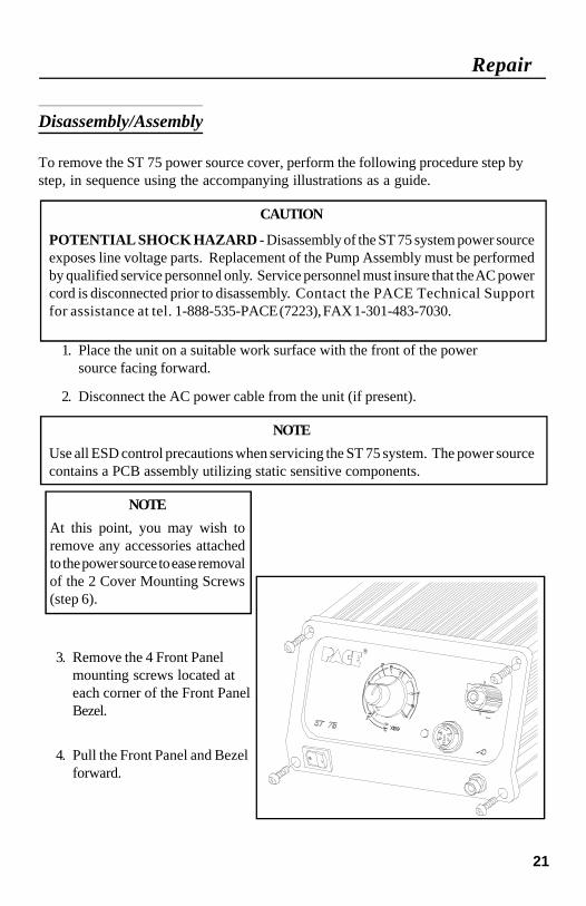
Disassembly/Assembly
To remove the ST 75 power source cover, perform the following procedure step bystep, in sequence using the accompanying illustrations as a guide.
CAUTION
POTENTIAL SHOCK HAZARD - Disassembly of the ST 75 system power sourceexposes line voltage parts. Replacement of the Pump Assembly must be performedby qualified service personnel only. Service personnel must insure that the AC powercord is disconnected prior to disassembly. Contact the PACE Technical Supportfor assistance at tel. 1-888-535-PACE (7223), FAX 1-301-483-7030.
1. Place the unit on a suitable work surface with the front of the powersource facing forward.
2. Disconnect the AC power cable from the unit (if present).
NOTE
Use all ESD control precautions when servicing the ST 75 system. The power sourcecontains a PCB assembly utilizing static sensitive components.
Repair
NOTE
At this point, you may wish toremove any accessories attachedto the power source to ease removalof the 2 Cover Mounting Screws(step 6).
3. Remove the 4 Front Panelmounting screws located ateach corner of the Front PanelBezel.
4. Pull the Front Panel and Bezelforward.

22
Repair
5. Remove the 3 upper RearPanel mounting screws.
6. Reposition the unit with therear of the power sourcefacing forward.
7. A Cover Mounting Screw islocated on each side of thepower source (positioned bottom center).Remove the 2 Cover Mounting Screws.
8. Lift the Cover from the power source. Set Cover aside.
9. The power source components are now exposed for servicing. Whenreplacing the Main PCB Assembly or the Motor Pump Asembly, separateinstructions are supplied with the part.
10. To assemble the power source, perform steps 1 through 8 in reverse order,installing parts (e.g., screws) instead of removing.

23
Assembly Detail
�Rear Panel
�Motor Pump Assembly
� Front Panel
� PCB Assembly
� Transformer

24
Repair
Wiring Diagram

25
Repair
ST 75 Schematic, Sheet 1 of 2
Schematic

26
Repair

27
ST 75 Schematic, Sheet 2 of 2
Repair
Schematic Continued

28
Packing List/Spare Parts
Packing List
Table 3. Packing List
PACKING LIST Quantity Supplied
This is a packing list of the items shipped with thesystem and is current at the time of publication of thismanual.
ST 75 Systems ST 75-SX80Systems
Item # Description Part Number ST 75 ST 75E ST 75 ST 75E
1 ST 75 System Power Source - - - - - 1 1 1 1
2 SX-80 Handpiece, (48 Watts) 6010–0106 0 0 1 1
3 Power Supply Cord, 115 VAC 1332–0094 1 0 1 0
4 Power Supply Cord, 230 VAC 1332–0093 0 1 0 1
5 Tip & Tool Stand Kit 6019-0060-P1 0 0 1 1
6 SX-80 Accessory Kit - - - - - 0 0 1 1
7 Air Fitting Adaptor 1259–0081 0 1 0 1
8 Operation & MaintenanceManual 5050–0456 1 1 1 1
9 Tip Tool 1100–0206 0 0 1 1

29
Packing List/Spare Parts
Spare Parts
Table 4. Spare Parts
Item # Description Part Number
Power Source Replacement Parts
1Fuse,(F1), 1.25 Amp Time Lag, 115 Volt Systems 1159-0251
0.63 Amp Time Lag, 230 Volt Systems 1159-0252
2Power Cord 115 Volt Systems 1332-0094
230 Volt Systems 1332-0093
3 Power Switch 1157-0081
4 Bumpon (rubber foot) 1274-0021
5 PCB Assembly 6020-0129-P1
6 Motor Pump Assembly 1336-0037-P1
Accessories & Spare Parts (partial list, complete listing in catalogue)
7 Tip & Temperature Selection System Booklet 5050-0251
8 SX-80 Sodr-X-Tractor Handpiece 6010-0106-P1
9 SX-80 Heater Assembly 6010-0107-P1
10 PS-80 Soldering Iron Handpiece 6010-0096-P1
11 DTP-80 Dual ThermoPik Handpiece 7029-0001-P1
12 TT-65 ThermoTweez Handpiece 7025-0001-P1
13 TP-65 ThermoPik Handpiece 7024-0001-P1
14 TJ-70 ThermoJet Handpiece 7023-0002-P1

30
LIMITED WARRANTYPACE warrants that this equipment will be free of defects in materials and workmanship for a period of one(1) year from the date of receipt by the first user.
This warranty does not cover repair or replacement required as a result of misuse, mishandling or improperstorage. Failure to perform recommended routine maintenance, alterations or repairs made other than inaccordance with PACE’s directions, or removal or alteration of identification plates in any way will void thiswarranty. This warranty is available only to the first user, but the exclusions and limitations therein apply to allpersons and entities.
This warranty does not apply to consumable items, such as tips, filter elements, hoses, collection chambersetc., except that heaters are normally warranted for a period of six (6) months from the date of receipt by thefirst user.
PACE MAKES NO OTHER WARRANTY, EXPRESSED OR IMPLIED, AND MAKES NOWARRANTY OF MERCHANTABILITY OR FITNESS FOR A PARTICULAR PURPOSE.
PACE will, at its option, repair or replace any defective equipment or parts at its facility or other locationapproved by it at no charge to the user, or provide parts without charge for installation by the user in the fieldat user’s expense and risk. User will be responsible for all costs of shipping equipment to PACE or otherwarranty location for warranty service.
EXCEPT FOR THE REMEDY ABOVE DESCRIBED, UNLESS OTHERWISE REQUIRED BYAPPLICABLE LAW, PACE WILL HAVE NO OTHER OBLIGATION WITH REGARD TO ANYBREACH OF WARRANTY OR OTHER CLAIM WITH RESPECT TO THE EQUIPMENT, ORLIABILITY FOR ANY DIRECT, INDIRECT, CONSEQUENTIAL, OR INCIDENTAL LOSS ORDAMAGE CAUSED BY OR OCCURRING IN CONNECTION WITH ANY OF THE EQUIPMENT.
To obtain warranty service, contact the appropriate PACE company listed below
PACE Inc. 9893 Brewers Court, Laurel, Maryland 20723-1990Tel. (888) 535-7223 (toll-free) Warranty Service FAX 301 483 7030
PACE Europe Ltd. Sherbourne House Sherbourne Drive Tilbrook Milton KeynesUnited Kingdom MK7 8HXTel. (44) 01908 277 666 Warranty Service FAX (44) 01908 277 777
Do NOT return defective equipment or parts to PACE without obtaining prior authorization.
Any warranty or other claim with respect to the equipment must be made in writing and delivered to PACE(or local authorized PACE Distributor outside the U.S.) within a reasonable time of the expiration date of thiswarranty. Sufficient evidence of purchase and date of receipt must also be included, otherwise user’s rightsunder this warranty shall be deemed waived.