SSC-PNE Series - SEIKOH GIKENSSC-PNE).pdf · S05-H049-01E SSC-PNE Series 3 3.2 Physical Dimensions...
19
DOCUMENT NUMBER S05-H049-01E SSC-PNE Series Single mode SC CONNECTOR PLUG - for Angled-PC, Conical Shape - TECHNICAL SPECIFICATIONS Fiber Optic Products Division 296-1, MATSUHIDAI, MATSUDO-SHI, CHIBA, 270-2214 JAPAN. TEL: +81-47-388-6111 FAX: +81-47-388-4477
Transcript of SSC-PNE Series - SEIKOH GIKENSSC-PNE).pdf · S05-H049-01E SSC-PNE Series 3 3.2 Physical Dimensions...
DOCUMENT NUMBER S05-H049-01E
SSC-PNE Series
Single mode SC CONNECTOR PLUG - for Angled-PC, Conical Shape -
TECHNICAL SPECIFICATIONS
Fiber Optic Products Division
296-1, MATSUHIDAI, MATSUDO-SHI, CHIBA, 270-2214 JAPAN.
TEL: +81-47-388-6111 FAX: +81-47-388-4477
S05-H049-01E SSC-PNE Series
ii
SSC-PNE Series Single mode SC CONNECTOR PLUG - for Angled-PC, Conical Shape - TECHNICAL SPECIFICATIONS NCD-69B8-01 September 1996 NCD-69B8-02 July 1999 NCD-69B8-03 April 2000 S05-H049-01E July 2006
Copyright © 1996 - 2006 by All right reserved.
The information contained herein shall not be reproduced or disclosed to any third party without the express written consent of SEIKOH GIKEN Co., Ltd. The specifications contained herein are subject to change without notice.
Please address any questions, comments, and suggestions to:
Frankfurt Branch Siemensstrasse 9 D-63263 Neu-Isenburg, Germany TEL: +49-6102-297-701 FAX: +49-6102-297-750
Headquarters 4405 International Blvd., Suite B109 Norcross, GA 30093 U.S.A. TEL: +1-770-279-6602 FAX: +1-770-279-8839
Northeastern Field Office 714 Executive Drive Princeton, NJ 08540 TEL: +1-609-279-0225 FAX: +1-609-279-0207
Western Field Office 21250 Hawthorne Boulevard, Suite 700 Torrance, CA 90503 TEL: +1-310-792-7450 FAX: +1-310-792-7451
Concordia Plaza 21/F Rm2111, 1 Science Museum Road, Tsim Sha Tsui East, Kowloon, Hong Kong. TEL: +852-26206551 FAX: +852-26206525
S05-H049-01E SSC-PNE Series
iii
TABLE OF CONTENTS
Section Page 1 SCOPE 1 2 PART NUMBER 1 3 GENERAL SPECIFICATIONS 2 3.1 Parts and Materials 2 3.2 Physical Dimensions 3 3.3 General Tolerance 3 3.4 Appearance 3 4 PACKING 3 5 IDENTIFICATION 3 6 HANDLING AND CARE 4 6.1 Conditions of Storage 4 6.2 Precautions of Use 4 6.3 Disposal 4
Table Table 1 Part Number 1 Table 2 Parts and Materials 2 Table 3 Parts and Materials of Main Body 2 Table 4 Physical Specifications 3 Table 5 General Tolerance 3
Figure Figure 1 SSC-PNE Series Connector Plug (for ø 3 mm cord) 5 Figure 2 SSC-PNE Series Connector Plug (for ø 2 mm cord) 6 Figure 3 SSC-PNE Series Connector Plug (for ø 0.9 mm buffered fiber) 7 Figure 4 SSC-PNE Series Connector Plug (for ø 0.9 mm buffered fiber, rubber boot) 8 Figure 5 Main Body 9 Figure 6 to 16 Dimensions of Parts 10 to 15

S05-H049-01E SSC-PNE Series
iv
S05-H049-01E SSC-PNE Series
1
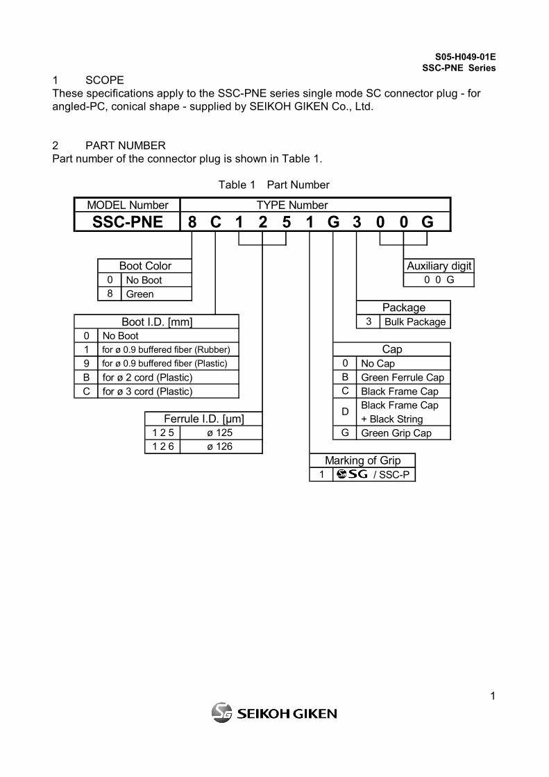
1 SCOPE These specifications apply to the SSC-PNE series single mode SC connector plug - for angled-PC, conical shape - supplied by SEIKOH GIKEN Co., Ltd. 2 PART NUMBER Part number of the connector plug is shown in Table 1.
Table 1 Part Number
MODEL Number TYPE NumberSSC-PNE 8 C 1 2 5 1 G 3 0 0 G
No Boot Green
Boot I.D. [mm] Bulk Package0 No Boot1 for ø 0.9 buffered fiber (Rubber)9 for ø 0.9 buffered fiber (Plastic) No CapB for ø 2 cord (Plastic) Green Ferrule CapC for ø 3 cord (Plastic) Black Frame Cap
Black Frame Cap + Black String Green Grip Cap
/ SSC-P
8
Boot Color0
1 2 6 ø 126
1
BC
3
Cap
1 2 5 ø 125Ferrule I.D. [µm]
Auxiliary digit0 0 G
D
G
Package
Marking of Grip
0
S05-H049-01E SSC-PNE Series
2
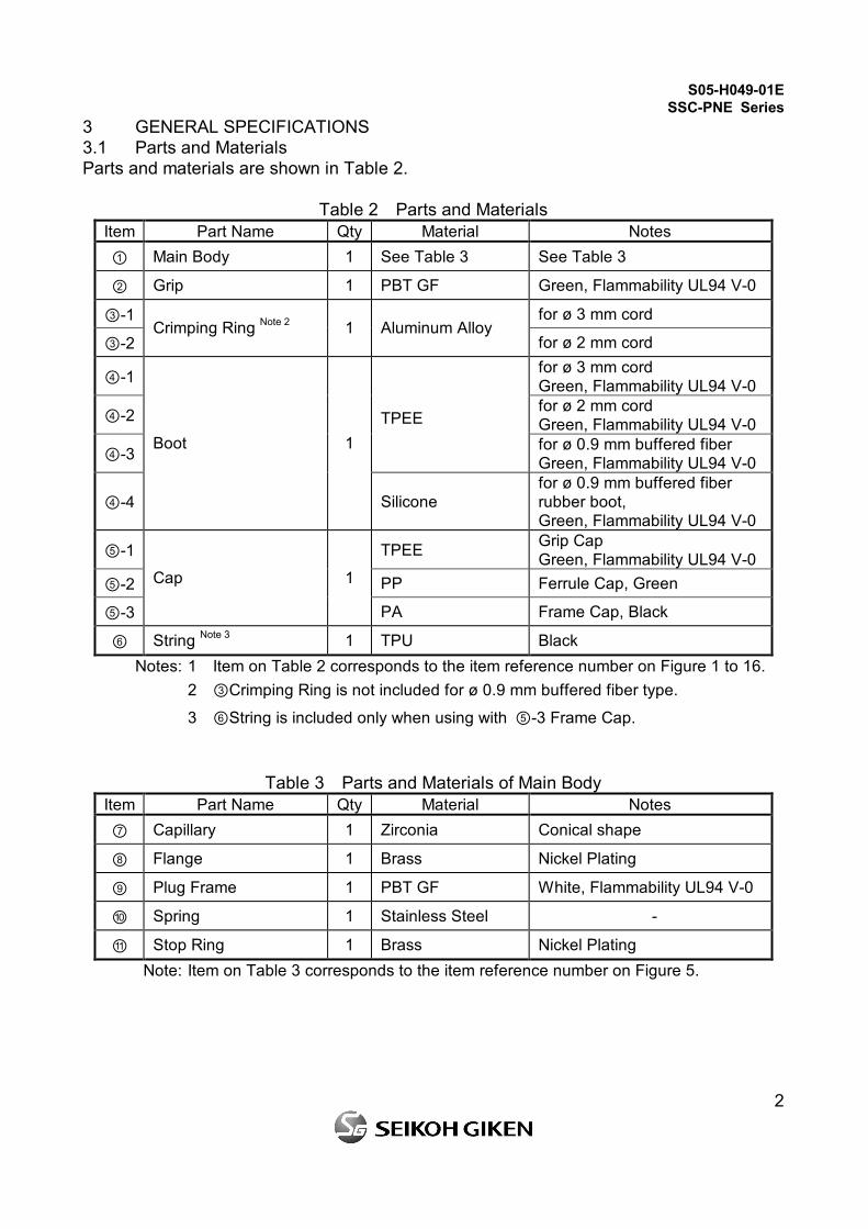
3 GENERAL SPECIFICATIONS 3.1 Parts and Materials Parts and materials are shown in Table 2.
Table 2 Parts and Materials Item Part Name Qty Material Notes ① Main Body 1 See Table 3 See Table 3
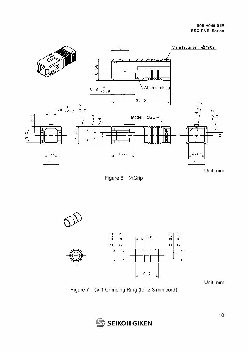
② Grip 1 PBT GF Green, Flammability UL94 V-0
③-1 for ø 3 mm cord
③-2 Crimping Ring Note 2 1 Aluminum Alloy
for ø 2 mm cord
④-1 for ø 3 mm cord Green, Flammability UL94 V-0
④-2 for ø 2 mm cord Green, Flammability UL94 V-0
④-3
TPEE for ø 0.9 mm buffered fiber Green, Flammability UL94 V-0
④-4
Boot 1
Silicone for ø 0.9 mm buffered fiber rubber boot, Green, Flammability UL94 V-0
⑤-1 TPEE Grip Cap Green, Flammability UL94 V-0
⑤-2 PP Ferrule Cap, Green
⑤-3
Cap 1
PA Frame Cap, Black
⑥ String Note 3 1 TPU Black Notes: 1 Item on Table 2 corresponds to the item reference number on Figure 1 to 16. 2 ③Crimping Ring is not included for ø 0.9 mm buffered fiber type.
3 ⑥String is included only when using with ⑤-3 Frame Cap.
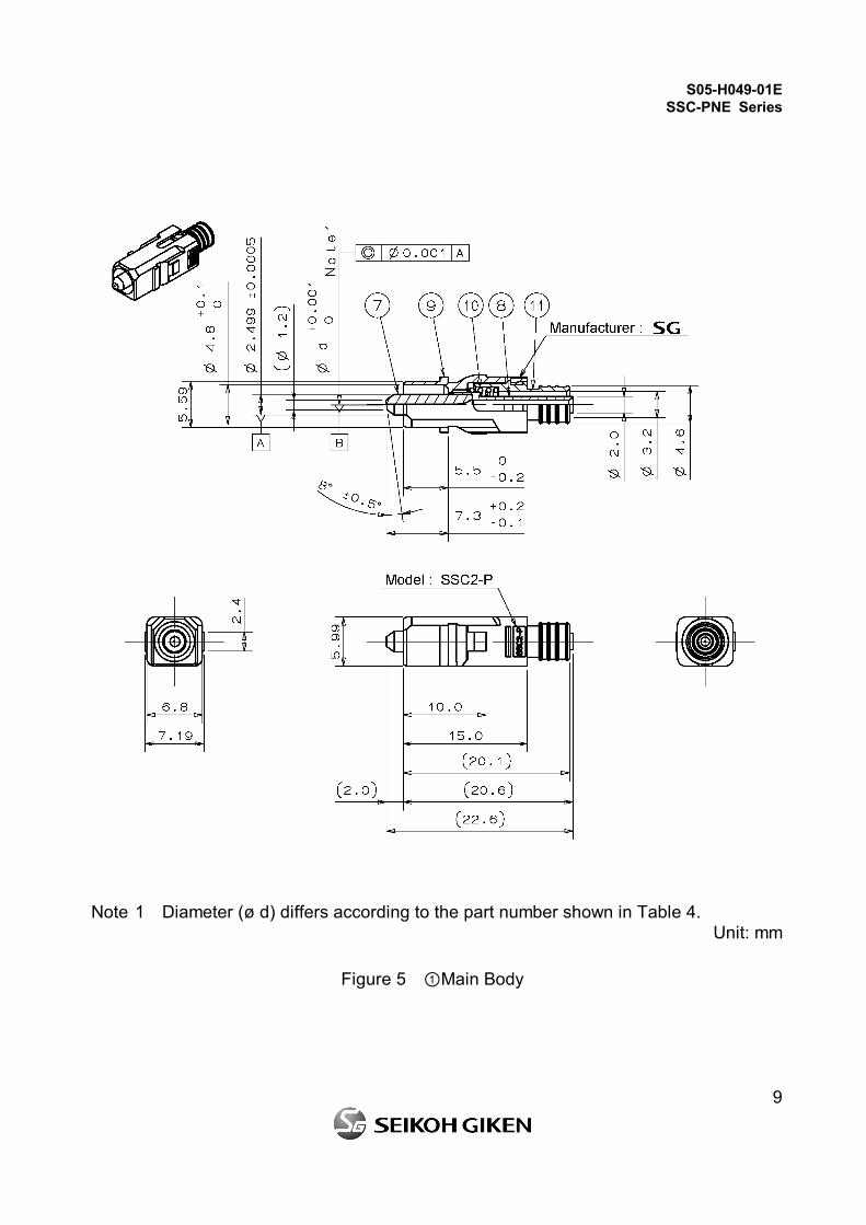
Table 3 Parts and Materials of Main Body Item Part Name Qty Material Notes ⑦ Capillary 1 Zirconia Conical shape
⑧ Flange 1 Brass Nickel Plating
⑨ Plug Frame 1 PBT GF White, Flammability UL94 V-0
⑩ Spring 1 Stainless Steel -
⑪ Stop Ring 1 Brass Nickel Plating Note: Item on Table 3 corresponds to the item reference number on Figure 5.
S05-H049-01E SSC-PNE Series
3
3.2 Physical Dimensions Figure 1 to 4 show the SSC-PNE series connector plugs. Figure 5 shows the main body. Figure 6 to 16 show the dimensions of the parts. Table 4 shows the physical specifications of the SSC-PNE series connector plug. · In accordance with IEC 61754-4 Type SC connector family. · In accordance with JIS C 5973 F04 Type connectors.
Table 4 Physical Specifications Items Part Number Specifications Remarks
SSC-PNE **125**300G ø 0.125 mm - Diameter (ø d) SSC-PNE **126**300G ø 0.126 mm -
3.3 General Tolerances Permissible deviation in dimensions without tolerance indication is in accordance with ISO 2768-m (JIS B 0405-m), as shown in Table 5.
Table 5 General Tolerance (ISO 2768-m) Basic size step [mm]
Over Under Permissible deviation [mm]
0.5 3 ±0.1 3 6 ±0.1 6 30 ±0.2
30 120 ±0.3 3.4 Appearance There should be no burr, peeling of plating or scratches that affect the product. 4 PACKING The product is packed to prevent damage during shipment. 5 IDENTIFICATION Identification label should indicate the part number and the lot number of the product(s) and should be permanently attached to the packing bag.
S05-H049-01E SSC-PNE Series
4
6 HANDLING AND CARE 6.1 Conditions of Storage Keep the product, in the packing bag, at the following conditions for its storage. · Storage temperature: -40 to +85 degrees C · Storage humidity: 0 to 85%RH, non-condensing 6.2 Precautions for Use Contamination, oil, sweat and others debris on the ferrule end face may influence the performance of the product. If contamination is on the ferrule end face, wipe the end face with the end face cleaner. 6.3 Disposal When discarding this product, please follow the regulations of your own country.

S05-H049-01E SSC-PNE Series
5
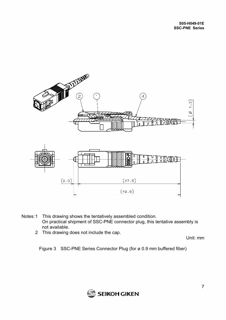
Notes: 1 This drawing shows the tentatively assembled condition. On practical shipment of SSC-PNE connector plug, this tentative assembly is not available.
2 This drawing does not include the cap. Unit: mm
Figure 1 SSC-PNE Series Connector Plug (for ø 3 mm cord)
S05-H049-01E SSC-PNE Series
6
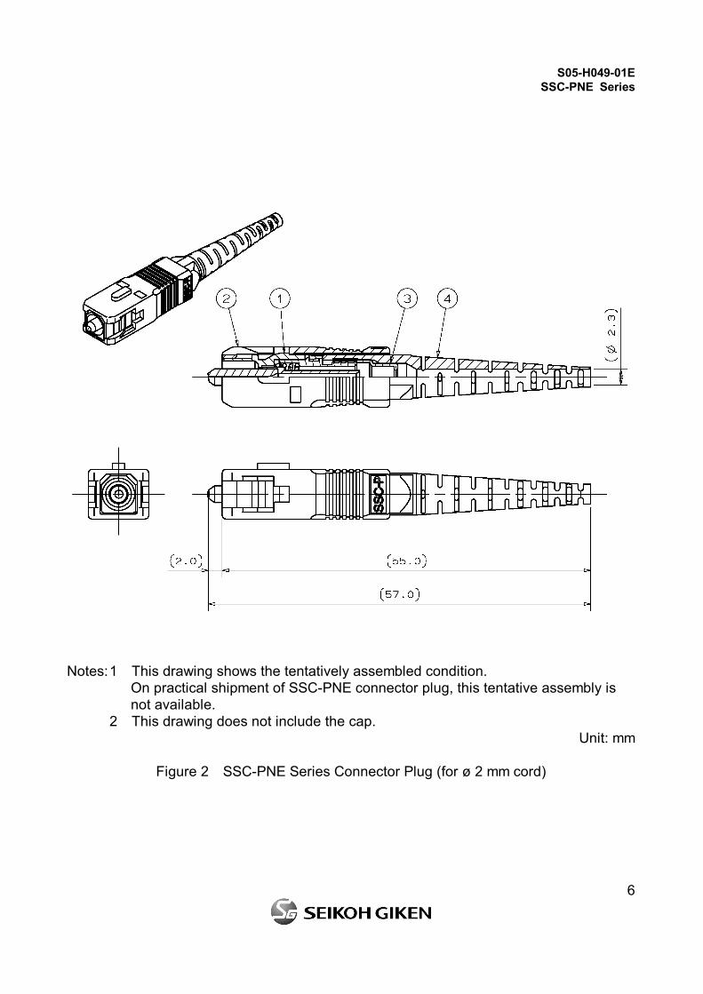
Notes: 1 This drawing shows the tentatively assembled condition. On practical shipment of SSC-PNE connector plug, this tentative assembly is not available.
2 This drawing does not include the cap. Unit: mm
Figure 2 SSC-PNE Series Connector Plug (for ø 2 mm cord)
S05-H049-01E SSC-PNE Series
7
Notes: 1 This drawing shows the tentatively assembled condition. On practical shipment of SSC-PNE connector plug, this tentative assembly is not available.
2 This drawing does not include the cap. Unit: mm
Figure 3 SSC-PNE Series Connector Plug (for ø 0.9 mm buffered fiber)
S05-H049-01E SSC-PNE Series
8
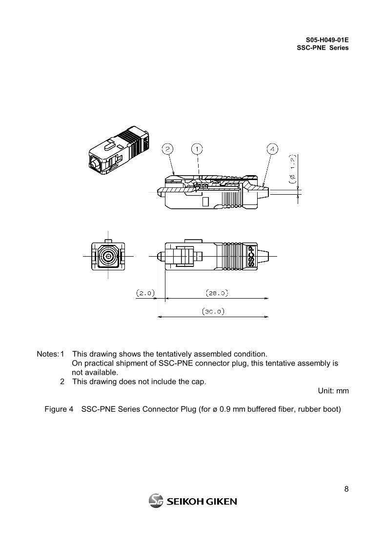
Notes: 1 This drawing shows the tentatively assembled condition. On practical shipment of SSC-PNE connector plug, this tentative assembly is not available.
2 This drawing does not include the cap. Unit: mm
Figure 4 SSC-PNE Series Connector Plug (for ø 0.9 mm buffered fiber, rubber boot)
S05-H049-01E SSC-PNE Series
9
Note 1 Diameter (ø d) differs according to the part number shown in Table 4. Unit: mm
Figure 5 ①Main Body
S05-H049-01E SSC-PNE Series
10
Unit: mm
Figure 6 ②Grip
Unit: mm
Figure 7 ③-1 Crimping Ring (for ø 3 mm cord)
S05-H049-01E SSC-PNE Series
11
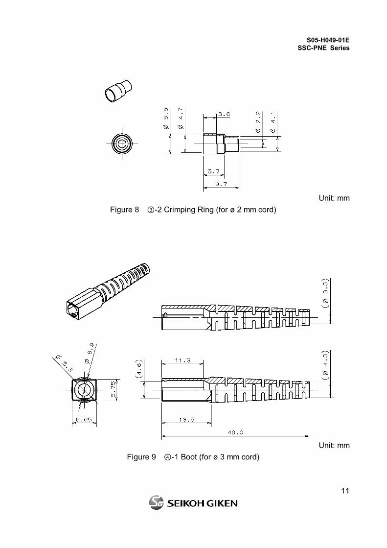
Unit: mm
Figure 8 ③-2 Crimping Ring (for ø 2 mm cord)
Unit: mm
Figure 9 ④-1 Boot (for ø 3 mm cord)
S05-H049-01E SSC-PNE Series
12
Unit: mm
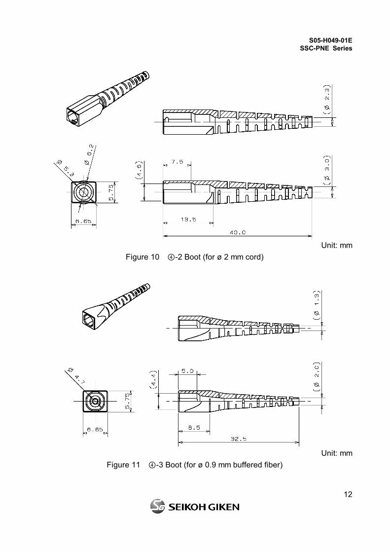
Figure 10 ④-2 Boot (for ø 2 mm cord)
Unit: mm
Figure 11 ④-3 Boot (for ø 0.9 mm buffered fiber)
S05-H049-01E SSC-PNE Series
13
Unit: mm
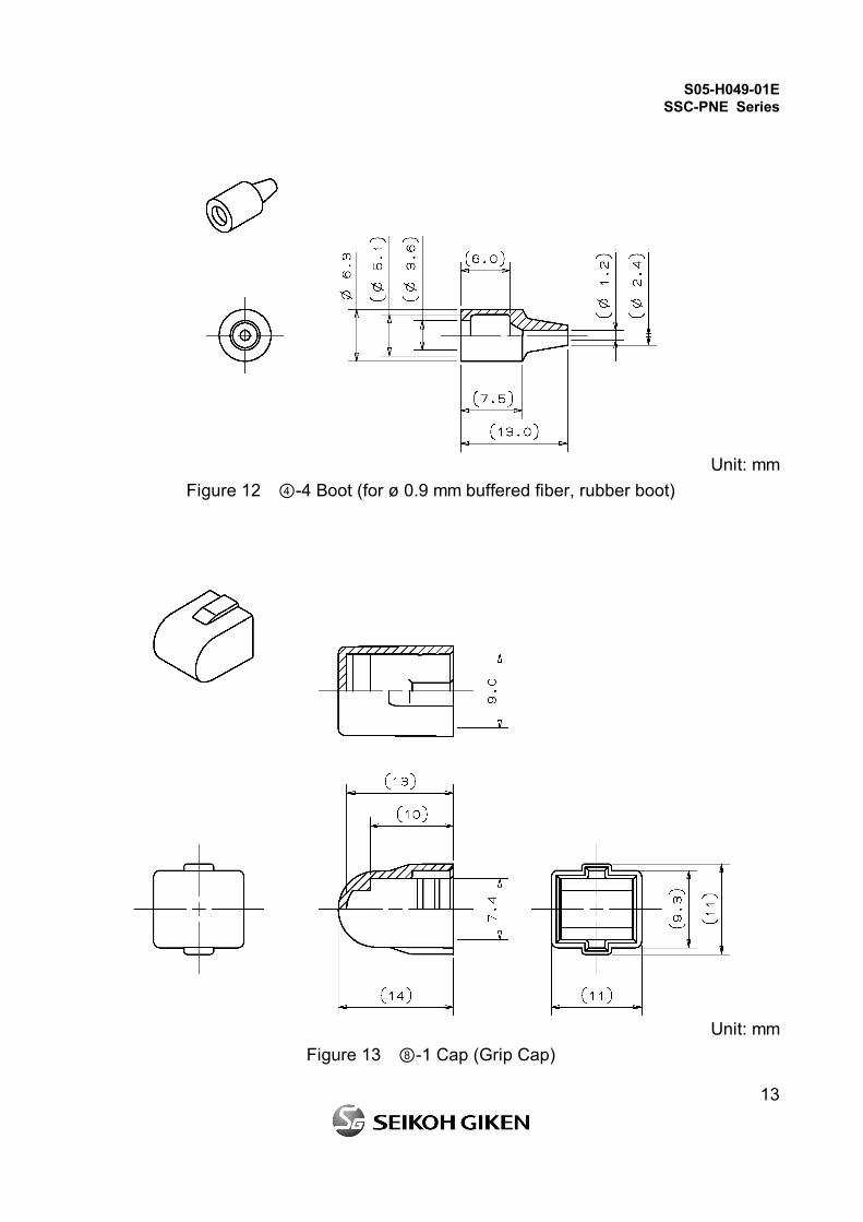
Figure 12 ④-4 Boot (for ø 0.9 mm buffered fiber, rubber boot)
Unit: mm
Figure 13 ⑧-1 Cap (Grip Cap)
S05-H049-01E SSC-PNE Series
14
Unit: mm
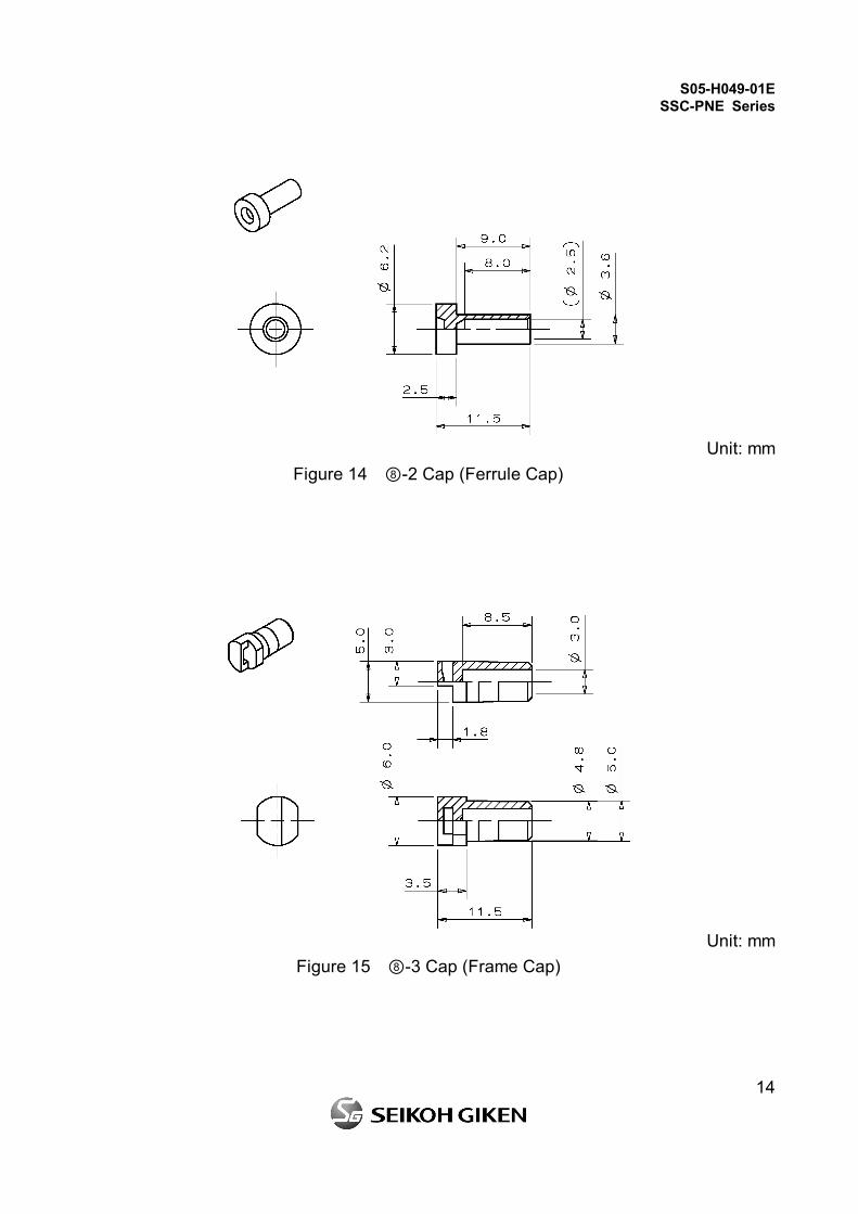
Figure 14 ⑧-2 Cap (Ferrule Cap)
Unit: mm
Figure 15 ⑧-3 Cap (Frame Cap)
S05-H049-01E SSC-PNE Series
15
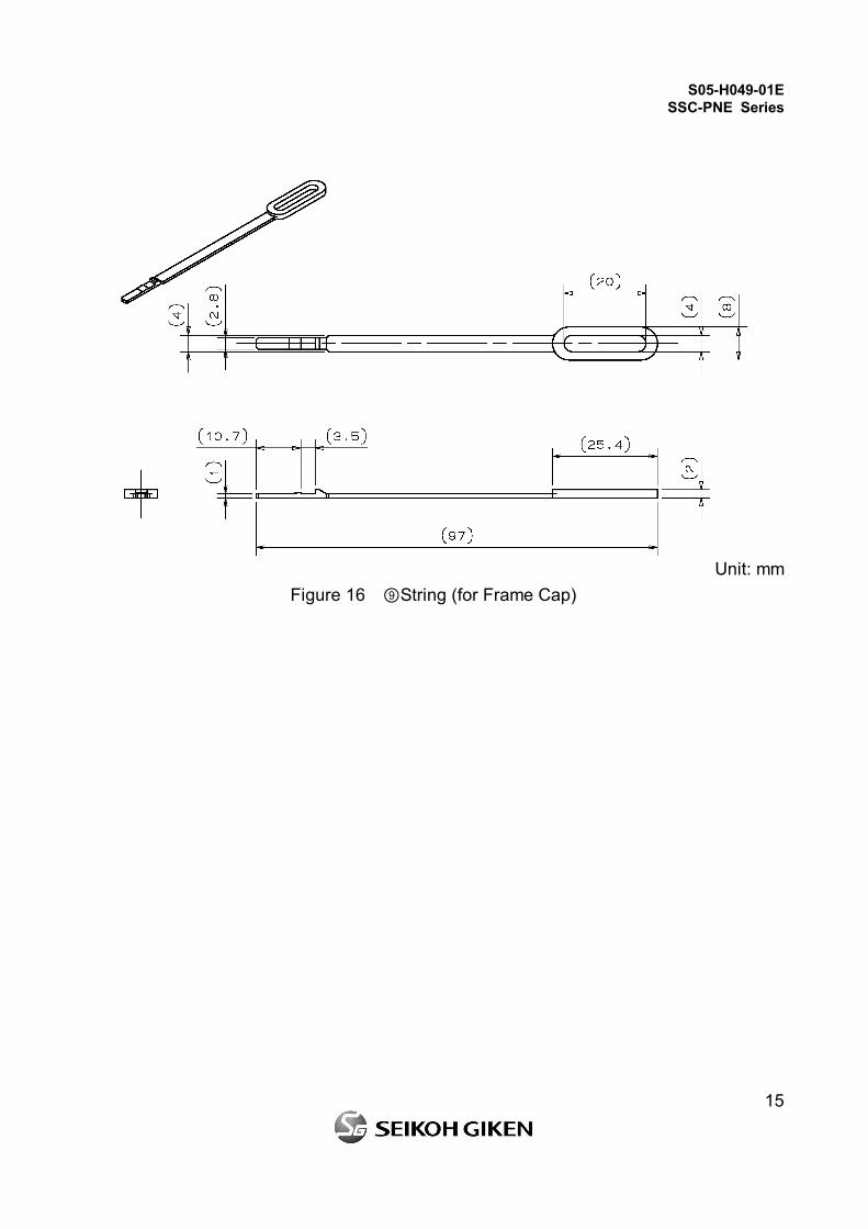
Unit: mm
Figure 16 ⑨String (for Frame Cap)