SS22G THRU SS220G
3
Maximum DC Blocking Voltage Parameter Maximum Repetitive Peak Reverse Voltage Maximum RMS voltage Maximum Average Forward Rectified Current Typical Junction Capacitance 20 40 V 14 28 V V 2.0 -55 ~ +125 A A V mA pF °C Units Surface Mount Schottky Barrier Rectifier Reverse Voltage - 20 to 200 V Forward Current - 2.0A Absolute Maximum Ratings and Electrical characteristics Ratings at ambient temperature unless otherwise specified.Single phase, half wave, 60Hz resistive or inductive load, for capacitive load, derate by 20 % 25 °C 20 40 Peak Forward Surge Current,8.3ms Single Half Sine-wave Superimposed on Rated Load (JEDEC method) Max Instantaneous Forward Voltage at 2 A Maximum DC Reverse Current at Rated DC Reverse Voltage Operating Junction Temperature Range SS22G SS24G SS26G SS28G SS210G SS212G SS215G SS220G PINNING PIN 1 2 DESCRIPTION Cathode Anode VRRM VRMS VDC I F(AV) I FSM VF Cj Tj Symbols Tstg Storage Temperature Range 60 42 60 80 56 80 100 100 0.55 0.70 0.85 220 -55 ~ +150 °C 120 120 150 105 150 200 140 200 0.95 80 50 70 84 Features • Metal silicon junction, majority carrier conduction • For surface mounted applications • Low power loss, high efficiency • High forward surge current capability • For use in low voltage, high frequency inverters, free wheeling, and polarity protection applications MECHANICAL DATA • Case: SMA • Terminals: Solderable per MIL-STD-750, Method 2026 • 60mg / 0.0021oz Approx. Weight: 0.5 5 T = 25°C a T =100°C a I R 0.3 3 80 Typical Thermal Resistance °C/W RθJA (1) (2) Top View Marking Code: SS22~SS220 Simplified outline SMA and symbol 1 2 Measured at 1 MHz and applied reverse voltage of 4 V D.C (2) (1) P.C.B. mounted with 2.0" X 2.0" (5 X 5 cm) copper pad areas. SS22G THRU SS220G 1 of 3 REV.08
Transcript of SS22G THRU SS220G
Maximum DC Blocking Voltage
Parameter
Maximum Repetitive Peak Reverse Voltage
Maximum RMS voltage
Maximum Average Forward Rectified Current
Typical Junction Capacitance
20 40 V
14 28 V
V
2.0
-55 ~ +125
A
A
V
mA
pF
°C
Units
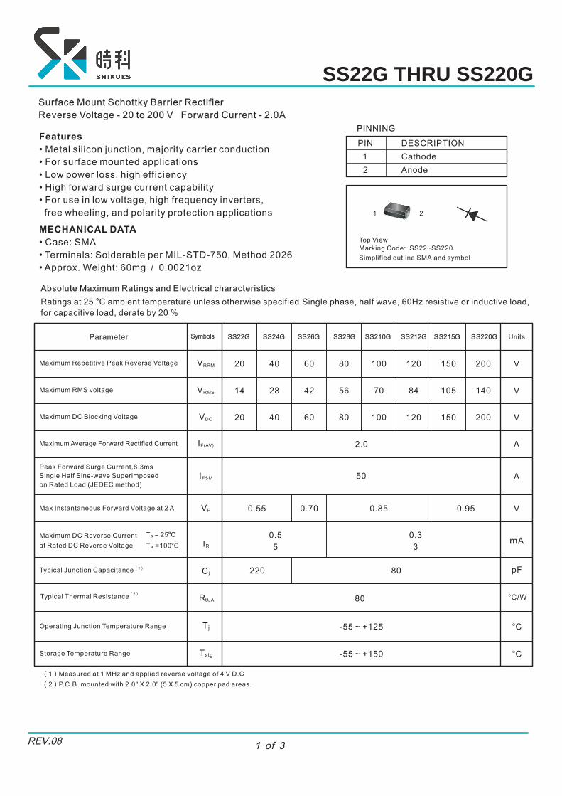
Surface Mount Schottky Barrier Rectifier
Reverse Voltage - 20 to 200 V Forward Current - 2.0A
Absolute Maximum Ratings and Electrical characteristics
Ratings at ambient temperature unless otherwise specified.Single phase, half wave, 60Hz resistive or inductive load,
for capacitive load, derate by 20 %
25 °C
20 40
Peak Forward Surge Current,8.3ms
Single Half Sine-wave Superimposed
on Rated Load (JEDEC method)
Max Instantaneous Forward Voltage at 2 A
Maximum DC Reverse Current
at Rated DC Reverse Voltage
Operating Junction Temperature Range
SS22G SS24G SS26G SS28G SS210G SS212G SS215G SS220G
PINNING
PIN
1
2
DESCRIPTION
Cathode
Anode
VRRM
VRMS
VDC
IF(AV)
IFSM
VF
C j
T j
Symbols
TstgStorage Temperature Range
60
42
60
80
56
80
100
100
0.55 0.70 0.85
220
-55 ~ +150 °C
120
120
150
105
150
200
140
200
0.95
80
50
70 84
Features
• Metal silicon junction, majority carrier conduction
• For surface mounted applications
• Low power loss, high efficiency
• High forward surge current capability
• For use in low voltage, high frequency inverters,
free wheeling, and polarity protection applications
MECHANICAL DATA
• Case: SMA
• Terminals: Solderable per MIL-STD-750, Method 2026
• 60mg / 0.0021ozApprox. Weight:
0.5
5
T = 25°Ca
T =100°Ca IR
0.3
3
80Typical Thermal Resistance °C/WRθJA
(1)
(2)
Top ViewMarking Code: SS22~SS220
Simplified outline SMA and symbol
1 2
Measured at 1 MHz and applied reverse voltage of 4 V D.C
(2)
(1)
P.C.B. mounted with 2.0" X 2.0" (5 X 5 cm) copper pad areas.
SS22G THRU SS220G
1 of 3REV.08

10
Fig.4 Typical Junction Capacitance
0.1
Ju
ncti
on
Ca
pa
cit
an
ce (
p
F)
Reverse Voltage (V)
10
100
200
500
20
50
1001
SS22G /SS24G
SS26G -SS220G
T =25J °C
0.10 0.4 1.4
Fig.3 Typical Forward Characteristic
Insta
ne
ou
s F
orw
ard
Cu
rre
nt
(A
)
Instaneous Forward Voltage (V)
1.0
10
0.60.2 0.8 1.0 1.2 1.81.6
SS22G /SS24G
SS26G /SS28G
SS210G /SS212G
SS215G /SS220G
20
Fig.1 Forward Current Derating Curve
0.5
1.0
1.5
2.0
2.5
3.0
0.025 50 75 100 125 150
Ave
rag
e F
orw
ard
Cu
rre
nt (A
)
Single phase half-wave 60 Hzresistive or inductive load
10 1001
10
20
30
00
40
60
50
Fig.5 Maximum Non-Repetitive Peak Forward Surage Current
Peak
A)
Forw
ard
Su
rage C
urr
ent
(
Number of Cycles at 60Hz
8.3 ms Single Half Sine Wave
(JEDEC Method)
SS22G -SS28G
SS210G -SS220G
Fig.2 Typical Reverse Characteristics
Insta
ne
ou
s C
urr
en
t ( μ
A)
Re
ve
rse
20 40 60 800
T =25J °C
T =100J °C
Percent of Rated Peak Reverse Voltage(%)
10010 0
101
10 2
10 3
10 4
T =75J °C
SS22G /SS24G
SS26G -SS220G
0.01 1001
10
100
Fig.6- Typical Transient Thermal Impedance
Tra
nsie
nt T
he
rma
l Im
pe
da
nce(
/W)
°C
t, Pulse Duration(sec)
0.1 1 10
Case Temperature (°C)
SS22G THRU SS220G
2 of 3REV.08

Marking
Type number Marking code
SS22G
SS24G
SS26G
SS22
SS28G
SS210G
SS212G
SS215G
SS220G
SS24
SS26
SS28
SS210
SS212
SS215
SS220
SMA
c
HE
V AM
E
D A
A
e
g g
e
PACKAGE OUTLINEPlastic surface mounted package; 2 leads
UNIT
mm2.2 0.314.83 2.9 5.4
1.9 0.124.32 2.3 4.7
max
min
A cD E HE g
0.9
1.5
e
1.2
1.7
milmax
min
87 190 114 213
75 170 91 185
12
5 35
59
47
67
2.2
(86)
1.8
(71)
1.8
(71
)
1.8
(71)
Unit :mm
(mil)
The recommended mounting pad size
SS22G THRU SS220G
3 of 3REV.08