SRS Series • Built in return stroke speed dampening ... Gas Springs/SRS Gas Springs.pdfH&O Die...
13
Smooth Return Gas Springs Dynamic Solutions for a Global Market ™ SRS Series • Built in return stroke speed dampening reduces pad bounce as much as 90%! • Increases part transfer efficiency • Stroke lengths from 125 mm to 300 mm • Retrofits to existing dies • Use as self-contained or in hosed system H&O Die Supply, Inc. 1-800-222-5441 [email protected]
Transcript of SRS Series • Built in return stroke speed dampening ... Gas Springs/SRS Gas Springs.pdfH&O Die...

Smooth Return Gas Springs
Dynamic Solutions for a Global Market™
SRS Series • Builtinreturnstrokespeeddampeningreducespadbounceasmuchas90%!
• Increasesparttransferefficiency
• Strokelengthsfrom125mmto300mm
• Retrofitstoexistingdies
• Useasself-containedorinhosedsystem
H&O Die Supply, Inc. 1-800-222-5441 [email protected]

�
Table of Contents
Page
Introduction.................................................4
FeaturesandBenefits................................4
ApplicationExamples.................................4
ForceCharts...............................................5
SRS750.....................................................6
SRS1500...................................................8
SRS3000.................................................10
SRS5000.................................................12
Accessories..............................................14
SRS Series
H&O Die Supply, Inc. 1-800-222-5441 [email protected]

�
TheSRSSmoothReturnSeriesisengineeredtoreducethepad
bounceassociatedwithincreasedreturnstrokespeedsfromthepress.
Theseinnovativegasspringsdeceleratethelast30mm/1.18in.ofthe
stroketobringtheoperationtoasmooth,controlledstop.
The SRS Smooth Return Series
Dam
peni
ngle
ngth
(≈ 3
0 m
m)
Features
Blank Holder Displacement vs Time
0
25
50
75
100
125
150
175
200
225
250
275
300
Time (s)
Dis
pla
cem
ent
(mm
)
max
6 m
m
≈ 50
mm
Press Speed 1.0 m/s
Blank Holder with SRS
Blank Holder without SRS
SRS dampening speed 0.4 m/s
Application Examples
• Increasesparttransferefficiency
•Strokelengthsfrom125mmto300mm
•Retrofitstoexistingdies
•Useasself-containedorinhosedsystem
•Built-inreturnstrokespeeddampeningtoeliminatepadbounce
Example1:ReplaceallstandardspringswithSRSSeries.
Example2:ReplacecornerstandardspringswithSRSSeries.
H&O Die Supply, Inc. 1-800-222-5441 [email protected]

�
SRS Force Charts
Performance: Allowable Strokes Per Minute
*Atambientroomtemperatureswithfreeairflow
SPM vs Stroke Length at max 150 bar charge pressure*
SRS 750
SRS 1500
SRS 3000
SRS 5000
0
5
10
15
20
25
30
125 150 175 200 225 250 275 300
Stroke Length (mm)
Max
Str
oke
s P
er M
inu
te (
SP
M)
SmoothReturn
StrokeLength(mm)
SRS 750 Force Chart (Lbs. force at 1�0 bar/�17� psi)mm 0 1�� 160 �00 ��0 �001�� 16�� 19�8160 16�� 1877 19�1�00 16�� 18�0 1886 19����0 16�� 179� 18�6 1887 19�7�00 16�� 1769 180� 18�� 1899 19�7
SRS 1500 Force Chart (Lbs. force at 1�0 bar/�17� psi)mm 0 1�� 160 �00 ��0 �001�� ���1 ��00160 ���1 �018 ���0�00 ���1 �89� �0�� ������0 ���1 �796 �91� �0�� �����00 ���1 �7�� �8�6 �9�9 �091 ����
SRS 3000 Force Chart (Lbs. force at 1�0 bar/�17� psi)mm 0 1�� 160 �00 ��0 �001�� 6619 8��8160 6619 806� 8�91�00 6619 77�7 81�6 86�1��0 6619 7�07 7800 816� 8690�00 6619 7��8 7�8� 7869 8��9 8690
SRS 5000 Force Chart (Lbs. force at 1�0 bar/�17� psi)mm 0 1�� 160 �00 ��0 �001�� 1118� 1��97160 1118� 1�776 1�7�1�00 1118� 1��16 1�9�� 1�8����0 1118� 1�786 1���0 1�987 1�977�00 1118� 1��0� 1�9�1 1���7 1�176 1�977
Example:SRS-5000X250at150barcanrunat10SPM.Notethatifyoureducethefillpressureto75bar,youcandoubletheSPMto20.
Note: To calculate Newtons, multiply Lbs. force by �.��8.
H&O Die Supply, Inc. 1-800-222-5441 [email protected]

6
Product Specifications
Pressure Medium ..............................................Nitrogen Gas
Max. Charging Pressure ..............................1�0 bar/�17� psi
Minimum Charging Pressure ......................... �� bar/�60 psi
Max. Operating Temperature .............................. 80°C/176°F
Max. Strokes per Minute ..... See Performance Chart, Page �
Dampening Length .......................................≈ �0mm/1.18 in.
Dampening Speed ................................0.�m/sec / 1.�1ft/sec
Repair Kit ............................................................. SRSSK-7�0
Inlet Valve ......................................................... �6-07�-��00
Charge Fitting ................................................ T�-770-G1/8-P
SRS 750
ø��mm0.98 in.
7mm0.28 in.
8mm0.31 in.
ø7�.�mm2.96 in.
�1mm0.83 in.
�mm0.12 in.
S
L
Y
For maintenance only, M8
G 1/8"Charge Port
�8.�mm1.11 in.
ø�0mm1.57 in.
M8 (�x),depth 1� mm,
0.51 in.
SRS 7�0 Dimensional InformationModel X Stroke Stroke (S) Contact Force Full Stroke Force L Y Weight
mm in. N lbs N lbs mm in. mm in. lbs
SRS-7�0X1�� 1�� 4.92
7�00 1665 8700 1960
��� 9.25 �60 14.17 13.45
SRS-7�0X160 160 6.30 �70 10.63 ��0 16.93 14.55
SRS-7�0X�00 �00 7.87 �10 12.20 �10 20.08 15.73
SRS-7�0X��0 ��0 9.84 �60 14.17 610 24.02 17.27
SRS-7�0X�00 �00 11.81 �10 16.14 710 27.95 18.92
90°
NOTE: All dimensions are nominal. Data shown are typical. Actual data for any particular unit may vary.
H&O Die Supply, Inc. 1-800-222-5441 [email protected]
7
Mounting Options
MPPart No. T�-1�00-MP
FCSPart No. T�-1�00-FCS
FCPartNo.T2-1500-FC
FFCPartNo.T2-1500-FFC
Ordering Options
SRS-750 X 160 — 2175
Model Stroke ChargePressure
See Max150bar/2175psi Dimensional Information Chart
Allgasspringsshippedatmaximumchargepressureunlessotherwisespecified.
1�mm.47 in.
100mm3.94 in.7�.�mm2.89 in.
ø11mm.43 in.
100mm3.94 in.
7�.�mm2.89 in.
ø10�mm4.09 in.
��mm.94 in.
d
e
a
b
c
f
ø1��mm4.80 in.
ø10�mm4.09 in.
ø7�.�mm2.89 in.
ø11mm.43 in.
�9mm1.14 in.
16mm.63 in.Body ø +1.0
+0.�
ø 40 mm1.57 in.
100 mm3.94 in. 73.5 mm
2.89 in.
ø 18 mm.71 in.
12 mm (2x).47 in.
ø 11 mm.43 in.
ø 9 mm.35 in.
14 mm.55 in.
ø 15 mm.59 in
19.8 mm.78 in.
M20
ø11mm.43 in.
ø9mm.35 in.
1�mm (�X).47 in.
1�mm.55 in.
19.8mm.78 in.
ø1�mm.59 in.
ø18mm.71 in.
100mm3.94 in. 7�.�mm
2.89 in.
ø�0mm1.57 in.
M�0
ø104 mm4.09 in.
90 mm3.54 in. 73.5 mm
2.89 in.
29 mm1.14 in.
16 mm.63 in.
ø11 mm.43 in.Body ø +1.0
+0.5
ø10�mm4.09 in.
90mm3.54 in.
7�.�mm2.89 in.
�9mm1.14 in.
16mm.63 in.
ø11mm.43 in.
Flanges ordered separately
H&O Die Supply, Inc. 1-800-222-5441 [email protected]

8
SRS 1500
Product Specifications
Pressure Medium ..............................................Nitrogen Gas
Max. Charging Pressure ..............................1�0 bar/�17� psi
Minimum Charging Pressure ......................... �� bar/�60 psi
Max. Operating Temperature .............................. 80°C/176°F
Max. Strokes per Minute ..... See Performance Chart, Page �
Dampening Length .......................................≈ �0mm/1.18 in.
Dampening Speed ................................0.�m/sec / 1.�1ft/sec
Repair Kit ........................................................... SRSSK-1�00
Inlet Valve ......................................................... �6-07�-��00
Charge Fitting ................................................ T�-770-G1/8-P
ø�6mm1.42 in.
7mm0.28 in.
8mm0.31 in.
ø9�.�mm3.75 in.
��mm0.94 in.
�mm0.12 in.
S
L
Y
For maintenance only, M8
G 1/8"Charge Port
��.�mm1.67 in.
ø60mm2.36 in.
M8 (�x),depth 1� mm,
0.51 in.
SRS 1�00 Dimensional InformationModel X Stroke Stroke (S) Contact Force Full Stroke Force L Y Weight
mm in. N lbs N lbs mm in. mm in. lbs
SRS-1�00X1�� 1�� 4.92
1�000 3375 19000 4275
��� 9.65 �70 14.57 20.24
SRS-1�00X160 160 6.30 �80 11.02 ��0 17.32 22.66
SRS-1�00X�00 �00 7.87 ��0 12.60 ��0 20.47 25.08
SRS-1�00X��0 ��0 9.84 �70 14.57 6�0 24.41 28.38
SRS-1�00X�00 �00 11.81 ��0 16.54 7�0 28.35 31.68
90°
NOTE: All dimensions are nominal. Data shown are typical. Actual data for any particular unit may vary.
H&O Die Supply, Inc. 1-800-222-5441 [email protected]

9
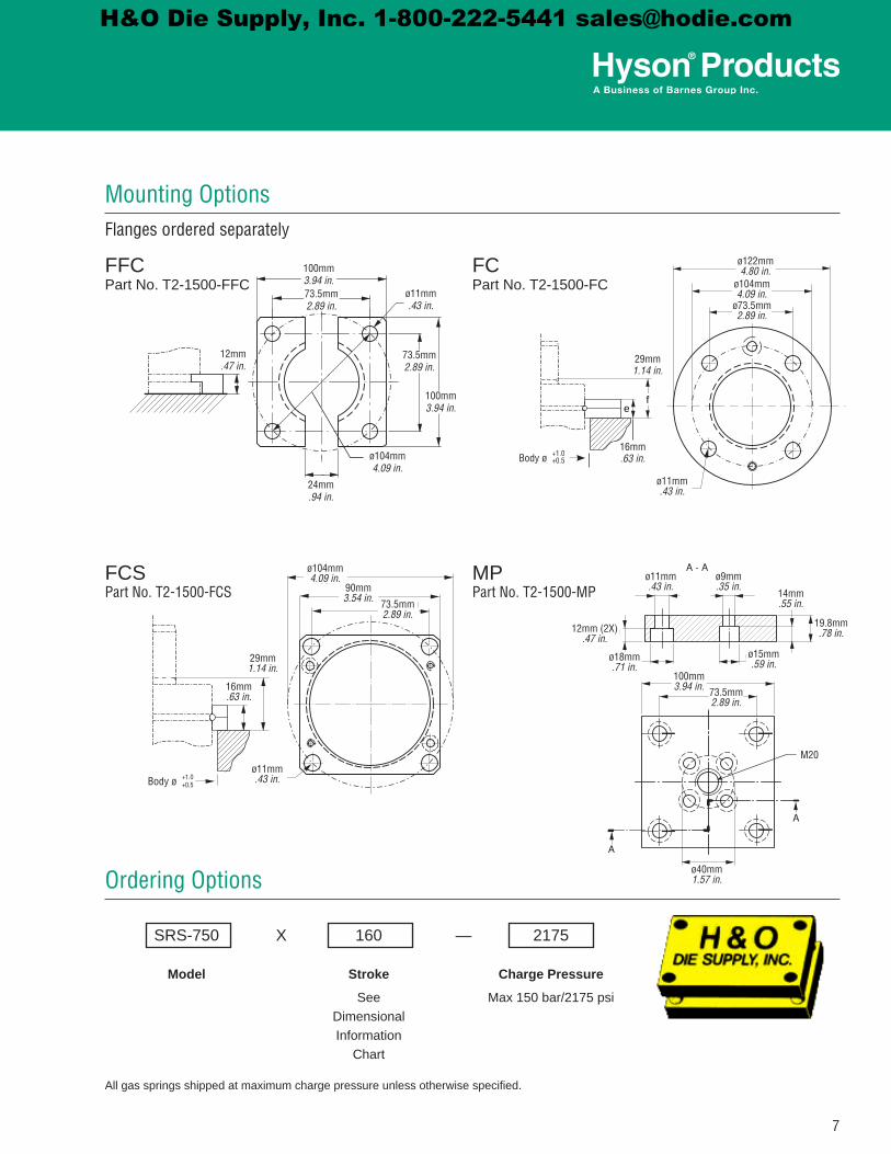
Ordering Options
SRS-1500 X 200 – 2175
Model Stroke ChargePressure
See Max150bar/2175psi Dimensional Information Chart
Allgasspringsshippedatmaximumchargepressureunlessotherwisespecified.
Mounting Options
MPPart No. T�-�000-MP
FCSPart No. T�-�000-FCS
FCPart No. T�-�000-FC
FFCPart No. T�-�000-FFC
1�mm.47 in.
1�0mm4.72 in.9�mm3.62 in.
ø1�.�mm.53 in.
1�0mm4.72 in.
9�mm3.62 in.
ø1�0mm5.12 in.
��mm.94 in.
d
e
a
b
c
f
ø1�0mm5.91 in.
ø1�0mm5.12 in.ø9�mm3.62 in.
ø1�.�mm.53 in.
��mm1.30 in.
18mm.71 in.Body ø +1.0
+0.�
ø 40 mm1.57 in.
100 mm3.94 in. 73.5 mm
2.89 in.
ø 18 mm.71 in.
12 mm (2x).47 in.
ø 11 mm.43 in.
ø 9 mm.35 in.
14 mm.55 in.
ø 15 mm.59 in
19.8 mm.78 in.
M20
ø1�.�mm.53 in.
ø9mm.35 in.
1�mm.51 in.
1�mm.55 in.
19.8mm.78 in.
ø1�mm.59 in.
ø�0mm.79 in.
1�0mm4.72 in. 9�mm
3.62 in.
ø60mm2.39 in.
M�0
ø104 mm4.09 in.
90 mm3.54 in. 73.5 mm
2.89 in.
29 mm1.14 in.
16 mm.63 in.
ø11 mm.43 in.Body ø +1.0
+0.5
ø1�0mm5.12 in.
110mm4.33 in.
9�mm3.62 in.
��mm1.30 in.
18mm.71 in.
ø1�.�mm.53 in.
Flanges ordered separately
H&O Die Supply, Inc. 1-800-222-5441 [email protected]

10
SRS 3000
Product Specifications
Pressure Medium ..............................................Nitrogen Gas
Max. Charging Pressure ..............................1�0 bar/�17� psi
Minimum Charging Pressure ......................... �� bar/�60 psi
Max. Operating Temperature .............................. 80°C/176°F
Max. Strokes per Minute ..... See Performance Chart, Page �
Dampening Length .......................................≈ �0mm/1.18 in.
Dampening Speed ................................0.�m/sec / 1.�1ft/sec
Repair Kit .......................................................... SRSSK-�000
Inlet Valve ......................................................... �6-07�-��00
Charge Fitting ................................................ T�-770-G1/8-P
ø�0mm1.97 in.
7mm0.28 in.
8mm0.31 in.
ø1�0.�mm4.73 in.
��.�mm1.00 in.
�mm0.12 in.
S
L
Y
For maintenance only, M8
G 1/8"Charge Port
�6.6mm2.23 in.
ø80mm3.15 in.
M10 (�x),depth 1� mm,
0.51 in.
SRS �000 Dimensional InformationModel X Stroke Stroke (S) Contact Force Full Stroke Force L Y Weight
mm in. N lbs N lbs mm in. mm in. lbs
SRS-�000X1�� 1�� 4.92
�0000 6750
�8000 8550 �6� 10.43 �90 15.35 23.54
SRS-�000X160 160 6.30 �8000 8550 �00 11.81 �60 18.11 25.05
SRS-�000X�00 �00 7.87 �8000 8550 ��0 13.39 ��0 21.26 26.62
SRS-�000X��0 ��0 9.84 �9000 8775 �90 15.35 6�0 25.20 28.82
SRS-�000X�00 �00 11.81 �9000 8775 ��0 17.32 7�0 29.13 30.80
90°
NOTE: All dimensions are nominal. Data shown are typical. Actual data for any particular unit may vary.
H&O Die Supply, Inc. 1-800-222-5441 [email protected]
11
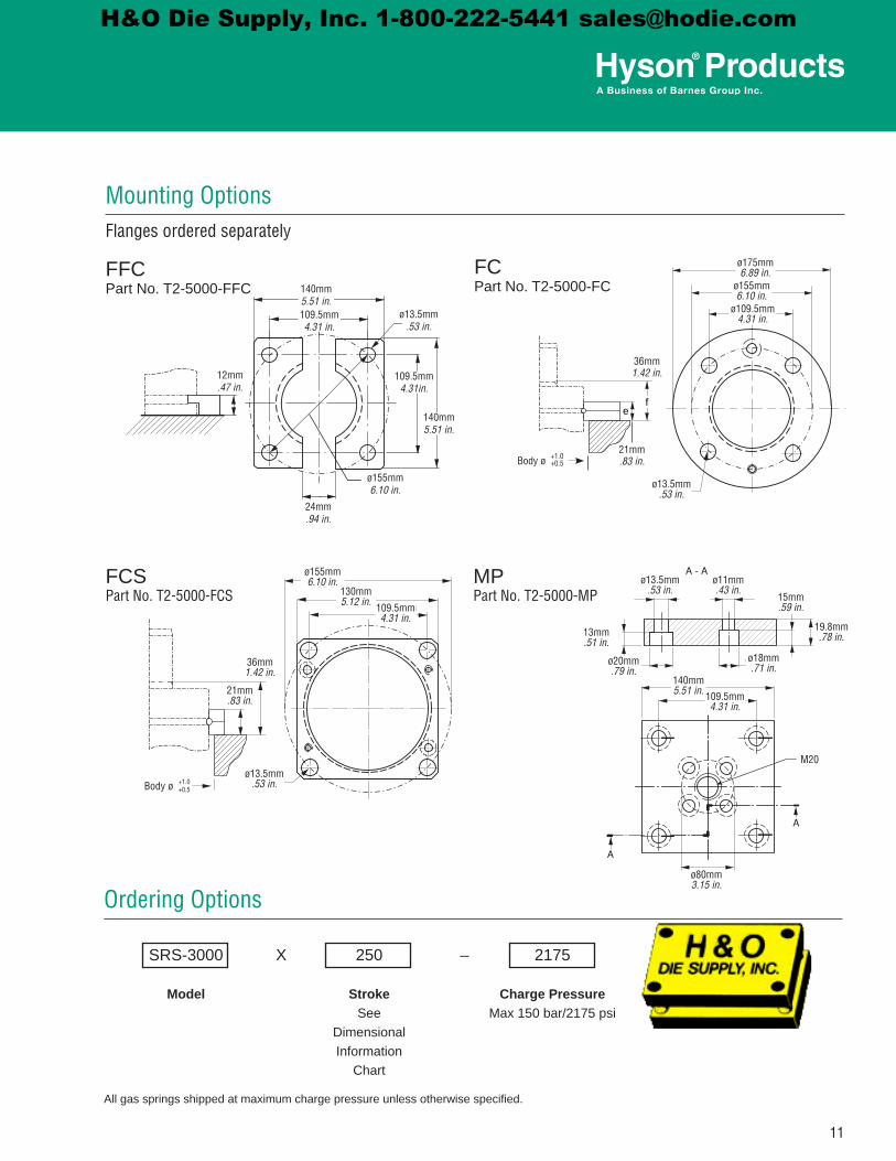
MPPart No. T�-�000-MP
Mounting Options
FFCPartNo.T2-5000-FFC
FCPartNo.T2-5000-FC
FCSPart No. T�-�000-FCS
Ordering Options
SRS-3000 X 250 – 2175
Model Stroke ChargePressure See Max150bar/2175psi Dimensional Information Chart
Allgasspringsshippedatmaximumchargepressureunlessotherwisespecified.
1�mm.47 in.
1�0mm5.51 in.109.�mm4.31 in.
ø1�.�mm.53 in.
1�0mm5.51 in.
109.�mm4.31in.
ø1��mm6.10 in.
��mm.94 in.
d
e
a
b
c
f
ø17�mm6.89 in.
ø1��mm6.10 in.
ø109.�mm4.31 in.
ø1�.�mm.53 in.
�6mm1.42 in.
�1mm.83 in.Body ø +1.0
+0.�
ø 40 mm1.57 in.
100 mm3.94 in. 73.5 mm
2.89 in.
ø 18 mm.71 in.
12 mm (2x).47 in.
ø 11 mm.43 in.
ø 9 mm.35 in.
14 mm.55 in.
ø 15 mm.59 in
19.8 mm.78 in.
M20
ø1�.�mm.53 in.
ø11mm.43 in.
1�mm.51 in.
1�mm.59 in.
19.8mm.78 in.
ø18mm.71 in.
ø�0mm.79 in.
1�0mm5.51 in. 109.�mm
4.31 in.
ø80mm3.15 in.
M�0
ø104 mm4.09 in.
90 mm3.54 in. 73.5 mm
2.89 in.
29 mm1.14 in.
16 mm.63 in.
ø11 mm.43 in.Body ø +1.0
+0.5
ø1��mm6.10 in.
1�0mm5.12 in.
109.�mm4.31 in.
�6mm1.42 in.
�1mm.83 in.
ø1�.�mm.53 in.
Flanges ordered separately
H&O Die Supply, Inc. 1-800-222-5441 [email protected]

1�
Product Specifications
Pressure Medium ..............................................Nitrogen Gas
Max. Charging Pressure ..............................1�0 bar/�17� psi
Minimum Charging Pressure ......................... �� bar/�60 psi
Max. Operating Temperature .............................. 80°C/176°F
Max. Strokes per Minute ..... See Performance Chart, Page �
Dampening Length .......................................≈ �0mm/1.18 in.
Dampening Speed ................................0.�m/sec / 1.�1ft/sec
Repair Kit ...........................................................SRSSK-�000
Inlet Valve ......................................................... �6-07�-��00
Charge Fitting ................................................ T�-770-G1/8-P
ø6�mm2.56 in.
8mm0.31 in.
8mm0.31 in.
ø1�0.�mm5.91 in.
�7.�mm1.08 in.
�mm0.12 in.
S
L
Y
For maintenance only, M8
G 1/8"Charge Port
70.7mm2.78 in.
ø100mm3.94 in.
M10 (�x),depth 1� mm,
0.51 in.
SRS �000 Dimensional InformationModel X Stroke Stroke (S) Contact Force Full Stroke Force L Y Weight
mm in. N lbs N lbs mm in. mm in. lbs
SRS-�000X1�� 1�� �.9�
�0000 11��0
6�000 1��00 �80 11.0� �0� 1�.9� �8.��
SRS-�000X160 160 6.�0 6�000 1�6�� �1� 1�.�0 �7� 18.70 6�.�8
SRS-�000X�00 �00 7.87 66000 1�8�0 ��� 1�.98 ��� �1.8� 69.7�
SRS-�000X��0 ��0 9.8� 66000 1�8�0 �0� 1�.9� 6�� ��.79 77.00
SRS-�000X�00 �00 11.81 66000 1�8�0 ��� 17.91 7�� �9.7� 8�.9�
90°
SRS 5000
NOTE: All dimensions are nominal. Data shown are typical. Actual data for any particular unit may vary.
H&O Die Supply, Inc. 1-800-222-5441 [email protected]
1�
Ordering Options
SRS-5000 X 300 – 2175
Model Stroke ChargePressure See Max150bar/2175psi Dimensional Information Chart
Allgasspringsshippedatmaximumchargepressureunlessotherwisespecified.
MPPart No. T�-7�00-MP
FCSPart No. T�-7�00-FCS
FCPart No. T�-7�00-FC
FFCPart No. T�-7�00-FFC
Mounting Options
1�mm.47 in.
190mm7.48 in.1�8mm5.43 in.
ø17.�mm.69 in.
190mm7.48 in.
1�8mm5.43 in.
ø19�.�mm7.69 in.
��mm.94 in.
d
e
a
b
c
f
ø��0mm8.66 in.
ø19�mm7.68 in.
ø1�8mm5.43 in.
ø17.�mm.69 in.
�1mm1.61 in.
�7mm1.06 in.Body ø +1.0
+0.�
ø 40 mm1.57 in.
100 mm3.94 in. 73.5 mm
2.89 in.
ø 18 mm.71 in.
12 mm (2x).47 in.
ø 11 mm.43 in.
ø 9 mm.35 in.
14 mm.55 in.
ø 15 mm.59 in
19.8 mm.78 in.
M20
ø17.�mm.69 in.
ø11mm.43 in.
17mm.67 in.
�0mm.79 in.
��mm.98 in.
ø18mm.71 in.
ø�6mm1.02 in.
190mm7.48 in. 1�8mm
5.43 in.
ø100mm3.94 in.
M�0
ø104 mm4.09 in.
90 mm3.54 in. 73.5 mm
2.89 in.
29 mm1.14 in.
16 mm.63 in.
ø11 mm.43 in.Body ø +1.0
+0.5
ø19�mm7.68 in.
16�mm6.38 in.
1�8mm5.43 in.
�1mm1.61 in.
�7mm1.06 in.
ø17.�mm.69 in.
Flanges ordered separately
H&O Die Supply, Inc. 1-800-222-5441 [email protected]

1�
Service Gauge Assembly
PartNo.:MGA-3000NH
CharginganddischargingSRSgasspringsforuseintheself-containedmodeissimple,usingtheMGA-3000NH.
Note:Malequickdisconnectchargefitting(T2-770-G1/8-P)issoldseparately.
Male Quick Disconnect Charge Fitting
PartNo.:T2-770-G1/8-P
TheT2-770-G1/8-PquickdisconnectisusedwiththeMGA-3000NHservicegaugeassemblytochargeanddischargeSRSgasspringsintheself-containedmode.
Nitrogen Charging Assembly
PartNos.NCA-2600&NCA-2600-HP
TheNCA-2600chargingassemblyisusedtotransfernitrogenfromacommercialbottletoSRSgassprings.ThechargingassemblyincludesaCGA-580bottlefitting,regulatorwithbottleandsystempressuregauges,shut-offvalveand10feetofhighpressurehosewithafittingforthecontrolpanelquickdisconnectinletortotheMGA-3000NHservicegaugeassembly.
Note:TheNCA-2600-HPisavailableforusewith3000-5000psibottles.CGA-680bottlefittingprovidedwithHPSeries.
SRS Accessories
GasSpringSealKitNumber
ToolKitNumber
SRS-750 SRSSK-750
T2TKSRS-1500 SRSSK-1500
SRS-3000 SRSSK-3000
SRS-5000 SRSSK-5000
Valve Removal and Installation Tool
AllSRSgasspringsusetheT2TK-IN-G1/8.
Seal Kits and Tool Kits
Control Panel
AllSRSgasspringsusetheCP-N2LGORcontrolpanelwithstandard-4JICandO-ringfacesealfittingsandhoses.
H&O Die Supply, Inc. 1-800-222-5441 [email protected]


![SRS-01 SRS-02 Encoder 4MPX-ASI Decoder ASI-4MPXUserManuals~SRS_[EN].pdf · SRS-02 Encoder 4MPX-ASI Decoder ASI-4MPX ... The package should contain: a. SRS-01. b. ... The SRS-02, as](https://static.fdocuments.in/doc/165x107/5abb735f7f8b9a441d8cd573/srs-01-srs-02-encoder-4mpx-asi-decoder-asi-usermanualssrsenpdfsrs-02-encoder.jpg)