SRM6300E-SLC - data-linc.comdata-linc.com/wp-content/uploads/2016/12/SRM6300E-SLC.pdfData-Linc...
31
USER GUIDE INDUSTRIAL DATA COMMUNICATIONS It is essential that all instructions contained in the User Guide are followed precisely to ensure proper operation of equipment. SRM6300E-SLC Frequency Hopping Spread Spectrum Ethernet Radio Modem
Transcript of SRM6300E-SLC - data-linc.comdata-linc.com/wp-content/uploads/2016/12/SRM6300E-SLC.pdfData-Linc...

USER GUIDE
IND
US
TR
IAL D
ATA C
OM
MU
NIC
AT
ION
S
It is essential that all instructions contained in the User Guide are followed precisely to ensure proper operation of equipment.
SRM6300E-SLC Frequency Hopping Spread Spectrum Ethernet Radio Modem

DATA-LINC GROUP PN 161-09979-002B
Product User Guide
FCC NotificationThis device complies with part 15 of the FCC rules. Operation is subject to the following conditions:
1) This device may not cause harmful interference and2) This device must accept any interference received, including interference that may cause undesired operation.
The device must be operated as supplied by Data-Linc Group. Any changes or modifications made to the device withoutthe express written approval of Data-Linc Group may void the user’s authority to operate the device.
Caution: This radio transmitter module has maximum transmitted output power of 500 mW. It is recommended thatthe transmit antenna be kept at least 23 cm away from nearby persons to satisfy FCC RF exposure requirements.
Note: This equipment has been tested and found to comply with the limits for a Class A digital device, pursuantto part 15 of the FCC Rules. These limits are designed to provide reasonable protection against harmful interfer-ence in an industrial installation. This equipment generates, uses and can radiate radio frequency energy and, ifnot installed and used in accordance with the instructions, may cause harmful interference to radio communica-tions. However, there is no guarantee that interference will not occur in a particular installation. If this equipmentdoes cause harmful interference to radio or television reception, which can be determined by turning the equip-ment off and on, the user is encouraged to try to correct the interference by one or more of the following mea-sures:
Reorient or relocate the receiving antenna.Increase the separation between the equipment and receiver.Connect the equipment into an outlet on a circuit different from that to which the receiver is connected.Consult the dealer or an experienced radio/TV technician for help.
Note: Whenever any Data-Linc Group series modem is placed inside an enclosure, a label must be placed onthe outside of that enclosure which includes the modem’s FCC ID.
The following types of antennas are approved for use with Data-Linc Group’s series modems. Consult Data-Linc GroupSales for particular model numbers. Only Data-Linc Group approved antennas can be legally used with this Data-LincGroup equipment. Antennas are available both as individual items or as part of a pre-made kit that includes cables.
2.4GHz Omni Directional Antenna 2.4GHz Directional Antenna
niaGBd5
niaGBd0
niaGBd6.6
Note: The antenna used for this device must be professionally installed on a fixed-mounted permanentoutdoor structure for satisfying RF exposure requirements, including antenna co-location requirements of1.1307(b)(3).

DATA-LINC GROUP 1
SRM6300E-SLC User’s Guide
PN 161-09979-002Crev 3/30/04
Table of ContentsPage
Introduction 3Quick Start 4
Modem Configuration 6Main Menu Option (0): Set Operation Mode 8Main Menu Option (1): Set Baud Rate 10Main Menu Option (2): Edit Call Book 10Main Menu Option (3): Edit Radio Transmission Characteristics 12Main Menu Option (4): Show Radio Statistics 16Main Menu Option (5): Edit Multi-Point Parameters 18Main Menu Option (8): Password 21
Modem Location 22Using an External Antenna 22Modem Front Panel LED’s 23Sample Data Communication Links 25
Technical Specifications 27
Troubleshooting 28
Technical Support 29Return Material Authorization 29Contact Information 29
○ ○ ○ ○ ○ ○ ○ ○ ○ ○ ○ ○ ○ ○ ○ ○ ○ ○ ○ ○ ○ ○ ○ ○ ○ ○ ○ ○ ○ ○ ○ ○ ○ ○ ○ ○ ○ ○ ○ ○ ○ ○ ○ ○ ○ ○ ○ ○ ○ ○ ○ ○
○ ○ ○ ○ ○ ○ ○ ○ ○ ○ ○ ○ ○ ○ ○ ○ ○ ○ ○ ○ ○ ○ ○ ○ ○ ○ ○ ○ ○ ○ ○ ○ ○ ○ ○ ○ ○ ○ ○ ○ ○ ○ ○ ○ ○ ○ ○ ○ ○ ○ ○ ○
○ ○ ○ ○ ○ ○ ○ ○ ○ ○ ○ ○ ○ ○ ○ ○ ○ ○ ○ ○ ○ ○ ○ ○ ○ ○ ○ ○ ○ ○ ○ ○ ○ ○ ○ ○ ○ ○ ○ ○ ○ ○ ○ ○ ○ ○
○ ○ ○ ○ ○ ○ ○ ○ ○ ○ ○ ○ ○ ○ ○ ○ ○ ○ ○ ○ ○ ○ ○ ○ ○ ○ ○ ○ ○ ○ ○ ○ ○
○ ○ ○ ○ ○ ○ ○ ○ ○ ○ ○ ○ ○ ○ ○ ○ ○ ○ ○ ○ ○ ○ ○ ○ ○ ○ ○ ○ ○ ○ ○ ○ ○ ○ ○ ○
○ ○ ○ ○ ○ ○ ○ ○ ○ ○ ○ ○ ○ ○ ○ ○ ○ ○ ○ ○ ○ ○ ○ ○ ○ ○ ○ ○ ○ ○ ○ ○ ○ ○ ○ ○
○ ○ ○ ○ ○ ○ ○ ○ ○ ○ ○ ○ ○ ○ ○ ○ ○ ○ ○ ○
○ ○ ○ ○ ○ ○ ○ ○ ○ ○ ○ ○ ○ ○ ○ ○ ○ ○ ○ ○ ○ ○ ○ ○ ○ ○ ○ ○ ○ ○ ○ ○
○ ○ ○ ○ ○ ○ ○ ○ ○ ○ ○ ○ ○ ○ ○ ○ ○ ○ ○ ○ ○ ○ ○ ○ ○ ○ ○ ○
○ ○ ○ ○ ○ ○ ○ ○ ○ ○ ○ ○ ○ ○ ○ ○ ○ ○ ○ ○ ○ ○ ○ ○ ○ ○ ○ ○ ○ ○ ○ ○ ○ ○ ○ ○ ○ ○ ○
○ ○ ○ ○ ○ ○ ○ ○ ○ ○ ○ ○ ○ ○ ○ ○ ○ ○ ○ ○ ○ ○ ○ ○ ○ ○ ○ ○ ○ ○ ○ ○ ○ ○ ○ ○ ○ ○ ○ ○ ○ ○ ○ ○ ○ ○ ○ ○ ○
○ ○ ○ ○ ○ ○ ○ ○ ○ ○ ○ ○ ○ ○ ○ ○ ○ ○ ○ ○ ○ ○ ○ ○ ○ ○ ○ ○ ○ ○ ○ ○ ○ ○ ○ ○ ○ ○ ○ ○ ○ ○ ○
○ ○ ○ ○ ○ ○ ○ ○ ○ ○ ○ ○ ○ ○ ○ ○ ○ ○ ○ ○ ○ ○ ○ ○ ○ ○ ○ ○ ○ ○ ○ ○ ○ ○ ○ ○ ○ ○ ○ ○ ○ ○ ○
○ ○ ○ ○ ○ ○ ○ ○ ○ ○ ○ ○ ○ ○ ○ ○ ○ ○ ○ ○ ○ ○ ○ ○ ○ ○ ○ ○ ○ ○ ○ ○ ○ ○ ○ ○ ○
○ ○ ○ ○ ○ ○ ○ ○ ○ ○ ○ ○ ○ ○ ○ ○ ○ ○ ○ ○ ○ ○ ○ ○ ○ ○ ○ ○ ○ ○ ○ ○ ○ ○ ○ ○ ○ ○ ○ ○ ○ ○ ○ ○
○ ○ ○ ○ ○ ○ ○ ○ ○ ○ ○ ○ ○ ○ ○ ○ ○ ○ ○ ○ ○ ○ ○ ○ ○ ○ ○ ○ ○ ○ ○ ○ ○ ○ ○ ○ ○ ○ ○ ○ ○ ○ ○ ○ ○ ○ ○ ○ ○
○ ○ ○ ○ ○ ○ ○ ○ ○ ○ ○ ○ ○ ○ ○ ○ ○ ○ ○ ○ ○ ○ ○ ○ ○ ○ ○ ○ ○ ○ ○ ○ ○ ○ ○ ○ ○ ○ ○ ○ ○ ○ ○ ○ ○ ○ ○ ○
○ ○ ○ ○ ○ ○ ○ ○ ○ ○ ○ ○ ○ ○ ○ ○ ○ ○ ○ ○ ○ ○ ○ ○ ○ ○ ○ ○ ○ ○ ○ ○ ○ ○ ○ ○ ○ ○ ○ ○ ○
○ ○ ○ ○ ○ ○ ○ ○ ○ ○ ○ ○ ○ ○ ○ ○ ○ ○ ○ ○ ○ ○ ○ ○ ○ ○ ○ ○ ○ ○ ○ ○ ○ ○ ○ ○ ○ ○ ○ ○ ○ ○ ○ ○ ○ ○ ○

DATA-LINC GROUP2 PN 161-09979-002Crev 3/30/04
SRM6300E-SLC User’s Guide

DATA-LINC GROUP 3
SRM6300E-SLC User’s Guide
PN 161-09979-002Crev 3/30/04
IntroductionData-Linc Group’s SRM6300E-SLC has been designed to mount in an Allen-Bradley SLC 500 Slot Rack. The SRM6300E-SLC transceiver modem is a high performance, wireless radio modem designed for heavy-duty industrial datacommunications in the 2.4- 2.4835 GHz license-free band. It employs advanced spread spectrum frequency hopping anderror detection technology to achieve very reliable, noise and interference immune operation. A high RF data rate of 188kbpsand superior sensitivity provide ultra reliable data integrity. The SRM6300E-SLC has a rated range of up to 25 miles (40 km)and an installed range of up to 35 miles (56 km) in optimal conditions with line-of-sight and an omni directional antenna. Thiscan also be extended further with repeaters or higher gain antenna.
The SRM6300E-SLC can be operated in a number of different modes to satisfy a broad range of communicationsrequirements. It can be configured for point-to-point or multi-point operation with an unlimited number of remote sites on asingle master depending on data throughput requirements. Repeaters can be used in the system to extend range andeliminate dead RF zones that are blocked by obstructions.
An external antenna can be used with up to two hundred feet of coax. This provides a boost in signal strength and decreasesinduced noise levels. With an external antenna, radio modems can be located inside buildings or metallic enclosures.
Equipped with a 10 Base-T Ethernet port, the SRM6300E-SLC is easily connected via standard 10 Base-T Category 5 patchcord (provided) to an Allen-Bradley SLC 5/05 CPU ENET port, hub or any other device equipped with a 10 Base-T networkinterface.
The User Guide covers the operating modes and configurations that are available to users of the SRM6300E-SLC. It alsoprovides the user with bench testing instructions, technical information and specifications.
In most applications, the SRM6300E-SLC comes pre-configured for the application in which it is going to be used. In mostcases no other configuration is required. If you are unsure if the modem needs further configuration, please contact Data-LincGroup.
DATA-LINC GROUP4 PN 161-09979-002Crev 3/30/04
SRM6300E-SLC User’s Guide
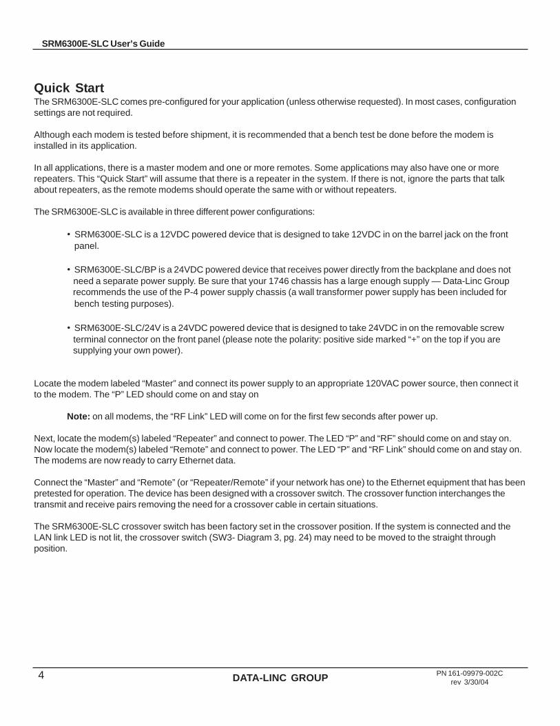
Quick StartThe SRM6300E-SLC comes pre-configured for your application (unless otherwise requested). In most cases, configurationsettings are not required.
Although each modem is tested before shipment, it is recommended that a bench test be done before the modem isinstalled in its application.
In all applications, there is a master modem and one or more remotes. Some applications may also have one or morerepeaters. This “Quick Start” will assume that there is a repeater in the system. If there is not, ignore the parts that talkabout repeaters, as the remote modems should operate the same with or without repeaters.
The SRM6300E-SLC is available in three different power configurations:
• SRM6300E-SLC is a 12VDC powered device that is designed to take 12VDC in on the barrel jack on the front panel.
• SRM6300E-SLC/BP is a 24VDC powered device that receives power directly from the backplane and does not need a separate power supply. Be sure that your 1746 chassis has a large enough supply — Data-Linc Group recommends the use of the P-4 power supply chassis (a wall transformer power supply has been included for bench testing purposes).
• SRM6300E-SLC/24V is a 24VDC powered device that is designed to take 24VDC in on the removable screw terminal connector on the front panel (please note the polarity: positive side marked “+” on the top if you are supplying your own power).
Locate the modem labeled “Master” and connect its power supply to an appropriate 120VAC power source, then connect itto the modem. The “P” LED should come on and stay on
Note: on all modems, the “RF Link” LED will come on for the first few seconds after power up.
Next, locate the modem(s) labeled “Repeater” and connect to power. The LED “P” and “RF” should come on and stay on.Now locate the modem(s) labeled “Remote” and connect to power. The LED “P” and “RF Link” should come on and stay on.The modems are now ready to carry Ethernet data.
Connect the “Master” and “Remote” (or “Repeater/Remote” if your network has one) to the Ethernet equipment that has beenpretested for operation. The device has been designed with a crossover switch. The crossover function interchanges thetransmit and receive pairs removing the need for a crossover cable in certain situations.
The SRM6300E-SLC crossover switch has been factory set in the crossover position. If the system is connected and theLAN link LED is not lit, the crossover switch (SW3- Diagram 3, pg. 24) may need to be moved to the straight throughposition.
DATA-LINC GROUP 5
SRM6300E-SLC User’s Guide
PN 161-09979-002Crev 3/30/04
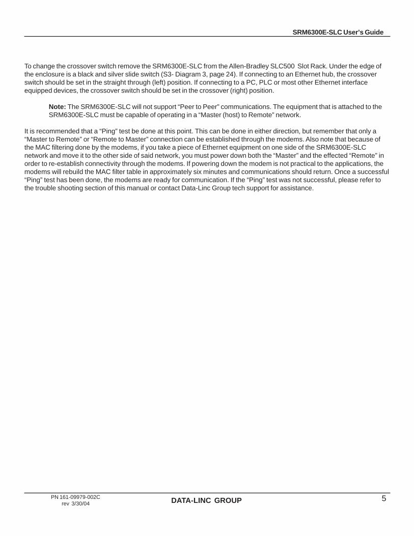
To change the crossover switch remove the SRM6300E-SLC from the Allen-Bradley SLC500 Slot Rack. Under the edge ofthe enclosure is a black and silver slide switch (S3- Diagram 3, page 24). If connecting to an Ethernet hub, the crossoverswitch should be set in the straight through (left) position. If connecting to a PC, PLC or most other Ethernet interfaceequipped devices, the crossover switch should be set in the crossover (right) position.
Note: The SRM6300E-SLC will not support “Peer to Peer” communications. The equipment that is attached to theSRM6300E-SLC must be capable of operating in a “Master (host) to Remote” network.
It is recommended that a “Ping” test be done at this point. This can be done in either direction, but remember that only a“Master to Remote” or “Remote to Master” connection can be established through the modems. Also note that because ofthe MAC filtering done by the modems, if you take a piece of Ethernet equipment on one side of the SRM6300E-SLCnetwork and move it to the other side of said network, you must power down both the “Master” and the effected “Remote” inorder to re-establish connectivity through the modems. If powering down the modem is not practical to the applications, themodems will rebuild the MAC filter table in approximately six minutes and communications should return. Once a successful“Ping” test has been done, the modems are ready for communication. If the “Ping” test was not successful, please refer tothe trouble shooting section of this manual or contact Data-Linc Group tech support for assistance.

DATA-LINC GROUP6 PN 161-09979-002Crev 3/30/04
SRM6300E-SLC User’s Guide
ConfigurationIn most cases, the SRM6300E-SLC comes pre-configured from the factory. However, it may sometimes be necessary tochange the configuration. Most parameters are changed in the radio section of the modem although there are a few settingsthat are set using switches. If you are not sure if you need to change the configuration of the SRM6300E-SLC, you probablydon’t. Please contact Data-Linc Group for further information if you are unsure about your configuration.
Switch SettingsTo access the switches, remove the modem from the SLC Rack. The switch bank (SW1-Diagram 3, pg. 24) is located in thecenter of the large PCB.
Note: Leave switch positions 4, 5 and 6 at factory setting of off unless otherwise directed by Data-Linc Group.Changing these switches requires a radio parameters change.
MAC Filtering FunctionAll devices capable of generating Ethernet traffic have a MAC (Medium Access Control) address. This address is used in thecommunications of Ethernet data.
The SRM6300E-SLC is factory set to perform MAC level filtering. This means that it learns all the MAC addresses from theLAN it is connected to, and only forwards data packets across the radio links which are destined for addresses locatedacross the radio link. The MAC filtering function is enabled by setting switch (SW2-Diagram 3, pg.24) to the on position.
The MAC address table can store up to 10,000 addresses. Each entry to the table has a lifetime of six minutes after whichthe address is deleted. This dynamic table building allows for the possibility of stations being removed from the LAN. The netresult of this filtering functionality is the reduction of unnecessary network traffic across the radio link.
Note: Many Ethernet networks have data packets that are not covered by the MAC filter function (broadcast packetsfor example). These packets can occupy tremendous amount of the network’s bandwidth and overwhelm theSRM6300E-SLC section of the network. If the SRM6300E-SLC’s are going to be installed where they are linked toan open network (on office network, etc.), a properly configured router or switch should be installed to protect themodems from excessive data traffic. If you are unsure about your network, please consult with your networkadministrator.

DATA-LINC GROUP 7
SRM6300E-SLC User’s Guide
PN 161-09979-002Crev 3/30/04
Radio Parameter ConfigurationThe SRM6300E-SLC allows you to set several parameters to suit your particular application. All adjustments are donethrough the SRM6300E-SLC setup program, a user interface that eliminates the need for setup diskettes or custom software.
To access the configuration menu, connect the radio modem’s configuration port to any terminal program with port settings of19.2Kbaud, 8 data bits, no parity and one stop bit. With the modem connected to the PC running the terminal program,press the Configure button. While any terminal program will work, examples for this manual were generated using theMicrosoft Windows 2000 application “HyperTerminal.”
Note: When using HyperTerminal, set Handshaking to none and use a standard straight through cable. If you areusing something other than HyperTerminal, it may be necessary to use a cable that has pins 4 and 6 connectedtogether on the modem side of the cable. Contact Data-Linc for further information.
Table 1: Terminal Settings
When the setup program is invoked the RF “IN” LED on the SRM6300E-SLC front panel will flash once when the Configurebutton is pressed and the RF “Link” LED will remain on for the entire time the radio modem is in setup mode.
The main menu provides the radio modem’s unique call book number and the set of choices for editing the operationalparameters and viewing the performance data.
Figure 1: Main Menu
retemaraP gnitteS
etaRduaB 00291
stiBataD 8
ytiraP enoN
stiBpotS 1
lortnoCwolF enoN
DATA-LINC GROUP8 PN 161-09979-002Crev 3/30/04
SRM6300E-SLC User’s Guide
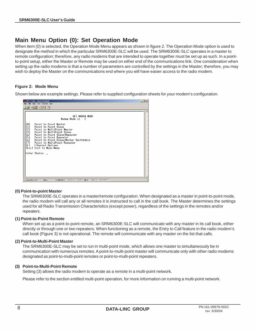
Main Menu Option (0): Set Operation ModeWhen item (0) is selected, the Operation Mode Menu appears as shown in figure 2. The Operation Mode option is used todesignate the method in which the particular SRM6300E-SLC will be used. The SRM6300E-SLC operates in a master toremote configuration; therefore, any radio modems that are intended to operate together must be set up as such. In a point-to-point setup, either the Master or Remote may be used on either end of the communications link. One consideration whensetting up the radio modems is that a number of parameters are controlled by the settings in the Master; therefore, you maywish to deploy the Master on the communications end where you will have easier access to the radio modem.
Figure 2: Mode Menu
Shown below are example settings. Please refer to supplied configuration sheets for your modem’s configuration.
(0) Point-to-point MasterThe SRM6300E-SLC operates in a master/remote configuration. When designated as a master in point-to-point mode,the radio modem will call any or all remotes it is instructed to call in the call book. The Master determines the settingsused for all Radio Transmission Characteristics (except power), regardless of the settings in the remotes and/orrepeaters.
(1) Point-to-Point RemoteWhen set up as a point-to-point remote, an SRM6300E-SLC will communicate with any master in its call book, eitherdirectly or through one or two repeaters. When functioning as a remote, the Entry to Call feature in the radio modem’scall book (Figure 3) is not operational. The remote will communicate with any master on the list that calls.
(2) Point-to-Multi-Point MasterThe SRM6300E-SLC may be set to run in multi-point mode, which allows one master to simultaneously be incommunication with numerous remotes. A point-to-multi-point master will communicate only with other radio modemsdesignated as point-to-multi-point remotes or point-to-multi-point repeaters.
(3) Point-to-Multi-Point RemoteSetting (3) allows the radio modem to operate as a remote in a multi-point network.
Please refer to the section entitled multi-point operation, for more information on running a multi-point network.

DATA-LINC GROUP 9
SRM6300E-SLC User’s Guide
PN 161-09979-002Crev 3/30/04
(4) Point-to-Point Remote/RepeaterOption 4 allows you to designate the radio modem to act as either a remote or a repeater, depending upon theinstructions received from the master for the specific communications session. When a radio modem is placed in anideal location, this setting offers the flexibility of using that radio modem as an end point in the communications link(remote) or to extend the link to a further point (repeater). These functions are not, however, available simultaneously (theradio modem cannot act as both a remote and a repeater at the same time).
Note: Configured as a repeater, a radio modem has no security features as explained below. When a radio modemis designated as a Point-to-Point Remote/Repeater, it will allow any master to use it as a repeater.
(5) Point-to-Point RepeaterSRM6300E-SLC radio modems allow the use of up to two repeaters in a communications link, significantly extending theoperating range. When designated as a repeater, a radio modem behaves as a pass-through link. All settings for the callbook, baud rates, and radio transmission characteristics are disabled. A repeater will connect with any master that callsit (the repeater must still be set up in the master’s call book).
The use of one repeater in a communications link will reduce the top data throughput available when compared to adirect master to remote link (generally on the order of 50%). The throughput does not decrease further if two repeatersare used.
(6) Point-to-Point Remote/Master SwitchableMode 6 is not applicable to the SRM6300E-SLC radio modems.
(7) Point-to-Multi-Point RepeaterSetting (7) allows the radio modem to operate as a repeater in a multi-point network.
Please refer to the section entitled, multi-point operation, for more information on running a multi-point network.
(F) Ethernet optionsThis selection is factory set and should not be changed.

DATA-LINC GROUP10 PN 161-09979-002Crev 3/30/04
SRM6300E-SLC User’s Guide
Main Menu Option (1): Set Baud RateThe baud rate setting affects the interface between the radio and Ethernet sections of the modem. All of the settings arefactory set and should not be changed.
Main Menu Option (2): Edit Call BookThe Call Book is an innovative feature in the SRM6300E-SLC that offers both security and flexibility in use. The Call Bookaccomplishes this by allowing the user to determine with which other SRM6300E-SLCs a given radio modem willcommunicate, based on the call book numbers for both the Master and Remote. The radio modem’s call book number isencoded in the microprocessor and identified on a label on the modem. The instructions provided in this section are for point-to-point mode only. Use of the Call Book for multi-point systems is explained later in this chapter. For two SRM6300E-SLCradio modems to communicate in point-to-point mode, three events must occur:
1. The call book number for the Master must be listed in the Remote’s Call Book.2. The call book number for the Remote must be listed in the Master’s Call Book.3. The Master must be programmed to call the remote.
As shown in figure 3, the Call Book allows users to set up a list of up to 10 SRM6300E-SLCs to communicate with,designate up to 2 repeaters to be used in communicating with a given radio modem, and tell the Master which remote to call.To direct the Master to call a remote, the Remote must be in the Call Book Menu. A specific remote may be called byentering (C) at the prompt, followed by the menu number corresponding to that remote. To call any available remote in thelist, the user should enter C and then A (for All).
Note: To call a remote through one or two repeaters, you must call that remote directly (as opposed to using theCall All option). When Call All is selected, the Master is not able to connect with any remotes through repeaters.This is because the Master calls every remote in the list when instructed to call all and will connect with the firstremote to respond. When calling through a repeater, the Master must first call that Repeater and establish acommunications link with it prior to making contact with the Remote.
Figure 3: Call Book Menu

DATA-LINC GROUP 11
SRM6300E-SLC User’s Guide
PN 161-09979-002Crev 3/30/04
Entering or Modifying Numbers in the Call BookEntering or modifying call book numbers in the Call Book is a straightforward process. When in the Call Book menu selectthe entry number (0 – 9) you wish to edit. You will be prompted for the new number (formatting is automatic, you do not needto enter the dash). Once the number is entered (unless it is 000-0000) you will be asked for the call number of the firstrepeater to be used. If no repeater is to be used, enter the escape key; your entry will be complete and you will be back inthe Call Book menu screen. If you enter a repeater number you will then be prompted for the call number of the secondrepeater to use. If a second repeater is being used, enter the call number at this time; if not then enter the escape key. Onceagain, the radio modem will retain your entries, as shown in the updated Call Book menu screen.
Note: It is important that the Call Book slots (0 – 9) are filled sequentially beginning with 0, the first slot in the book.Call book numbers do not need to be entered in numerical order; however, there must not be any 000-0000 numbersin the middle of the list of good call book numbers. The reason for this is that when a master is instructed to Call Allavailable remotes, it will call all remotes listed until it reaches the number of 000-0000. If a valid call book
number is entered after the all zero number, it will not be recognized as a valid number to be called by the Master.
Edit Call Book in Multi-Point SystemsIn a multi-point system the Remotes and Repeaters are not listed in the Master’s Call Book. When establishing such asystem, it is necessary only to have the Master’s call book number in each Remote’s and Repeater’s Call Book, and to haveeach repeater’s call book number in the Call Book of each remote which may potentially communicate through it.
The following example shows the Call Books of a multi-point system comprised of a master, repeater and remote in whichthe Remote can communicate either through the Repeater or directly to the Master:
Multi-Point Master Call Book (Unit Call book number 555-0001)
No call book number entries are necessary in the Master’s Call Book
The Master’s Call Book may be programmed to call any entry
Multi-Point Repeater Call Book (Unit Call book number 555-0002)
yrtnE rebmuN 1retaepeR 2retaepeR
)0( 0000-000
)1( 0000-000
yrtnE rebmuN 1retaepeR 2retaepeR
)0( 1000-555
)1( 0000-000
Multi-Point Remote Call Book (Unit Call book number 555-0003)
yrtnE rebmuN 1retaepeR 2retaepeR
)0( 1000-555
)1( 2000-555
)2( 0000-000

DATA-LINC GROUP12 PN 161-09979-002Crev 3/30/04
SRM6300E-SLC User’s Guide
Main Menu Option (3): Edit Radio Transmission CharacteristicsWhen option (3) is selected in the main menu, the screen in figure 4 appears, which allows the user to modify the radiotransmission characteristics of the radio modems. As stated in the warning, these parameters are for the experienced userwho has a good understanding of the principles of radio data transmission. They should be changed only after consulting thismanual.
It is important to note that the radio parameters between any radio modems in communication will be determined by thesettings for the Master (except when in multi-point mode, see (4) RF Data Rate and (5) RF Power below). While the settingsmay be modified for the Remote(s) and/or Repeaters, they will be overridden by the Master’s parameters.
Note: For most Ethernet applications, these settings are already optimized. Please consult with Data-Linc Groupbefore making changes.
Figure 4: Radio Parameters Menu
Shown below are example settings. Please refer to supplied configuration sheets for your modem’s configuration.
(0) FreqKey Selection (0) in the Radio Parameters menu allows the user to modify the hopping patterns of the radio modems to minimize the interference with other SRM6300E-SLC radio modems in operation in the area. For instance, if there were 10 pairs of SRM6300E-SLCs in operation within a factory or refinery, changing the Frequency Key would ensure that they would not jump onto the same frequencies at the same time for the same length of time.
There are 15 choices available for the Frequency Key (0-9 and A-E). It is recommended that a list be maintained of the settings for each master to ensure that each is set to a different hopping pattern.
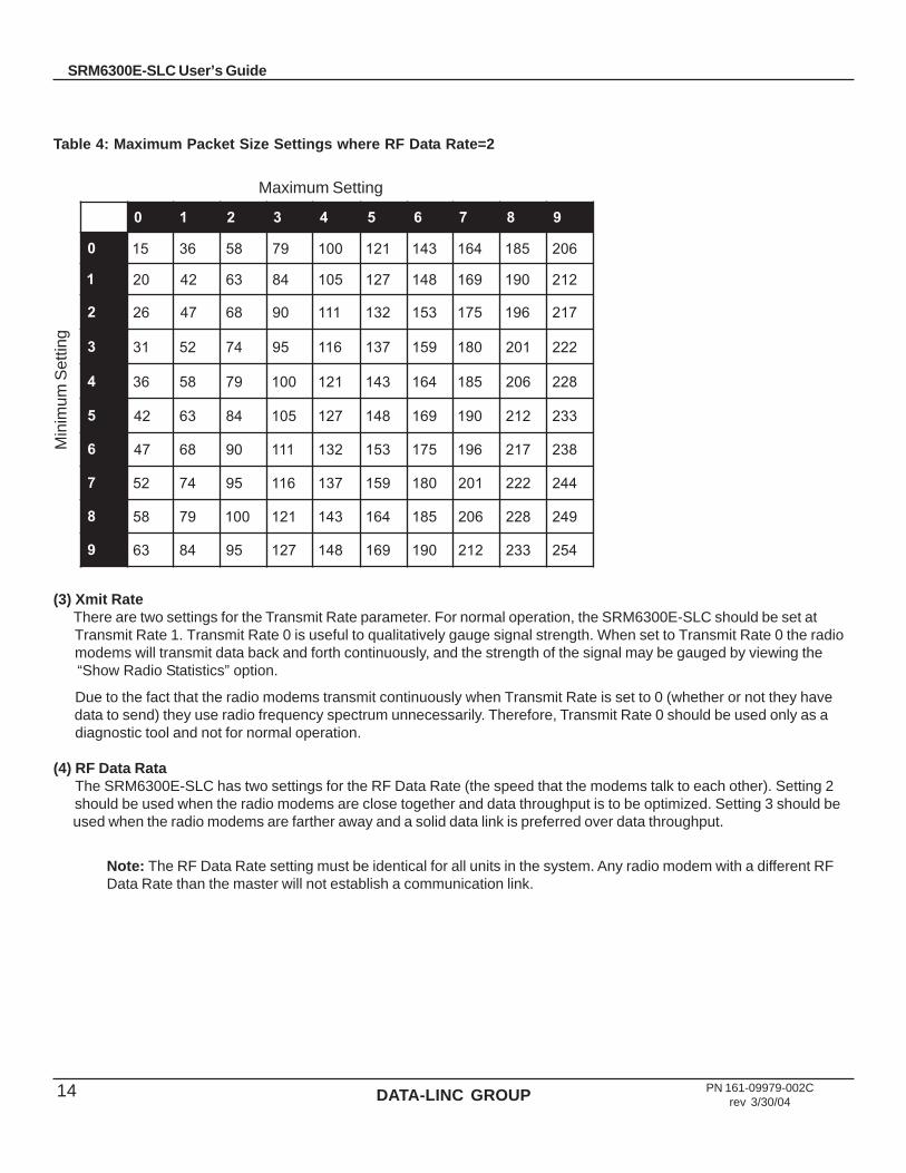
(1) Max Packet Size and (2) Min Packet Size Selections (1) and (2) allow the user to designate the size of the packets (in bytes) used by the radio modem in its communications link. This may be of particular value when using the SRM6300E-SLC with different communications software packages; you may find that throughput is optimized when packet sizes are restricted by the radio modem.
Packet size is determined by a combination of the settings entered by the user and the RF Data Rate. In addition, the Max Packet Size is a function of the setting selected for the Min Packet Size. Tables 2, 3 and 4 provide the packet sizes for each different combination of settings.

DATA-LINC GROUP 13
SRM6300E-SLC User’s Guide
PN 161-09979-002Crev 3/30/04
Table 2: Minimum Packet Size Settings (bytes)
gnitteS eziStekcaPniM2=etaRataDFR gnitteS eziStekcaPniM
3=etaRataDFR
0 61 0 8
1 12 1 21
2 62 2 61
3 23 3 02
4 73 4 42
5 24 5 82
6 84 6 23
7 35 7 63
8 85 8 04
9 46 9 44
Table 3: Maximum Packet Size Settings where RF Data Rate=3
0 1 2 3 4 5 6 7 8 9
0 8 42 04 65 27 88 401 021 631 251
1 21 82 44 06 67 29 801 421 041 651
2 61 23 84 46 08 69 211 821 441 061
3 02 63 25 86 48 001 611 231 841 461
4 42 04 65 27 88 401 021 631 251 861
5 82 44 06 67 29 801 421 041 651 271
6 23 84 46 08 69 211 821 441 061 671
7 63 25 86 48 001 611 231 841 461 081
8 04 65 27 88 401 041 631 251 861 481
9 44 06 67 29 801 421 041 651 271 881
Maximum Setting
Min
imum
Set
ting
DATA-LINC GROUP14 PN 161-09979-002Crev 3/30/04
SRM6300E-SLC User’s Guide
0 1 2 3 4 5 6 7 8 9
0 51 63 85 97 001 121 341 461 581 602
1 02 24 36 48 501 721 841 961 091 212
2 62 74 86 09 111 231 351 571 691 712
3 13 25 47 59 611 731 951 081 102 222
4 63 85 97 001 121 341 461 581 602 822
5 24 36 48 501 721 841 961 091 212 332
6 74 86 09 111 231 351 571 691 712 832
7 25 47 59 611 731 951 081 102 222 442
8 85 97 001 121 341 461 581 602 822 942
9 36 48 59 721 841 961 091 212 332 452
(3) Xmit Rate There are two settings for the Transmit Rate parameter. For normal operation, the SRM6300E-SLC should be set at Transmit Rate 1. Transmit Rate 0 is useful to qualitatively gauge signal strength. When set to Transmit Rate 0 the radio modems will transmit data back and forth continuously, and the strength of the signal may be gauged by viewing the “Show Radio Statistics” option.
Due to the fact that the radio modems transmit continuously when Transmit Rate is set to 0 (whether or not they have data to send) they use radio frequency spectrum unnecessarily. Therefore, Transmit Rate 0 should be used only as a diagnostic tool and not for normal operation.
(4) RF Data Rata The SRM6300E-SLC has two settings for the RF Data Rate (the speed that the modems talk to each other). Setting 2 should be used when the radio modems are close together and data throughput is to be optimized. Setting 3 should be used when the radio modems are farther away and a solid data link is preferred over data throughput.
Note: The RF Data Rate setting must be identical for all units in the system. Any radio modem with a different RFData Rate than the master will not establish a communication link.
Min
imum
Set
ting
Maximum Setting
Table 4: Maximum Packet Size Settings where RF Data Rate=2
DATA-LINC GROUP 15
SRM6300E-SLC User’s Guide
PN 161-09979-002Crev 3/30/04
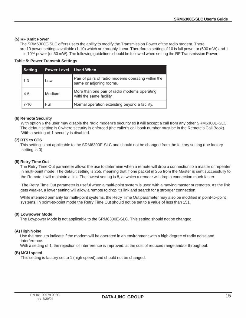
(5) RF Xmit Power The SRM6300E-SLC offers users the ability to modify the Transmission Power of the radio modem. There are 10 power settings available (1-10) which are roughly linear. Therefore a setting of 10 is full power or (500 mW) and 1
is 10% power (or 50 mW). The following guidelines should be followed when setting the RF Transmission Power:
Table 5: Power Transmit Settings
gnitteS leveLrewoP nehWdesU
3-1 woL ehtnihtiwgnitareposmedomoidarfosriapforiaP.smoorgninojdaroemas
6-4 muideM gnitareposmedomoidarforiapenonahteroM.ytilicafemasehtihtiw
01-7 lluF .ytilicafadnoyebgnidnetxenoitarepolamroN
(6) Remote Security With option 6 the user may disable the radio modem’s security so it will accept a call from any other SRM6300E-SLC. The default setting is 0 where security is enforced (the caller’s call book number must be in the Remote’s Call Book). With a setting of 1 security is disabled.
(7) RTS to CTS This setting is not applicable to the SRM6300E-SLC and should not be changed from the factory setting (the factory setting is 0)
(8) Retry Time Out The Retry Time Out parameter allows the use to determine when a remote will drop a connection to a master or repeater in multi-point mode. The default setting is 255, meaning that if one packet in 255 from the Master is sent successfully to the Remote it will maintain a link. The lowest setting is 8, at which a remote will drop a connection much faster.
The Retry Time Out parameter is useful when a multi-point system is used with a moving master or remotes. As the link gets weaker, a lower setting will allow a remote to drop it’s link and search for a stronger connection.
While intended primarily for multi-point systems, the Retry Time Out parameter may also be modified in point-to-point systems. In point-to-point mode the Retry Time Out should not be set to a value of less than 151.
(9) Lowpower Mode The Lowpower Mode is not applicable to the SRM6300E-SLC. This setting should not be changed.
(A) High Noise Use the menu to indicate if the modem will be operated in an environment with a high degree of radio noise and interference. With a setting of 1, the rejection of interference is improved, at the cost of reduced range and/or throughput.
(B) MCU speed This setting is factory set to 1 (high speed) and should not be changed.
DATA-LINC GROUP16 PN 161-09979-002Crev 3/30/04
SRM6300E-SLC User’s Guide
Main Menu Option (4): Show Radio StatisticsOption (4) in the main menu allows the user to view data transmission statistics which have been gathered by theTransceiver during the most recent session. Statistics are gathered during each data link and are reset when the next linkbegins. Ideally, noise levels should be below 30, and the difference between the average signal level and average noise levelshould be 30 or more. High noise levels tend to indicate other sources of RF interference, while low signal levels indicate aweak link. The “Local” stats are the statistics that are being gathered by the modem you are connected too while “Remote1,Remote2, and Remote3” are the stats of the Repeater(s) that the modem you are attached to is using to get back to theMaster modem. The following sections provide information useful to the process of troubleshooting and improving radio links.
Average Noise LevelThe average noise level indicates the level of background noise and interference at this modem and at each of the modemsused as repeaters in the link. The number is an average of the noise levels measured at each frequency in the modems’frequency hop table. The individual measurement values at each frequency hop channel are shown in the frequency table.The frequency table is accessed by pressing the ENTER key on the computer when the radio statistics menu is displayed.Average noise levels will typically fall in the range of 15 to 30. Average noise levels significantly higher than this are anindication of a high level of interference that may degrade the performance of the link. High noise levels can often be improvedwith bandpass filters, antenna placement or antenna polarization. Please contact Data-Linc Group for more information.
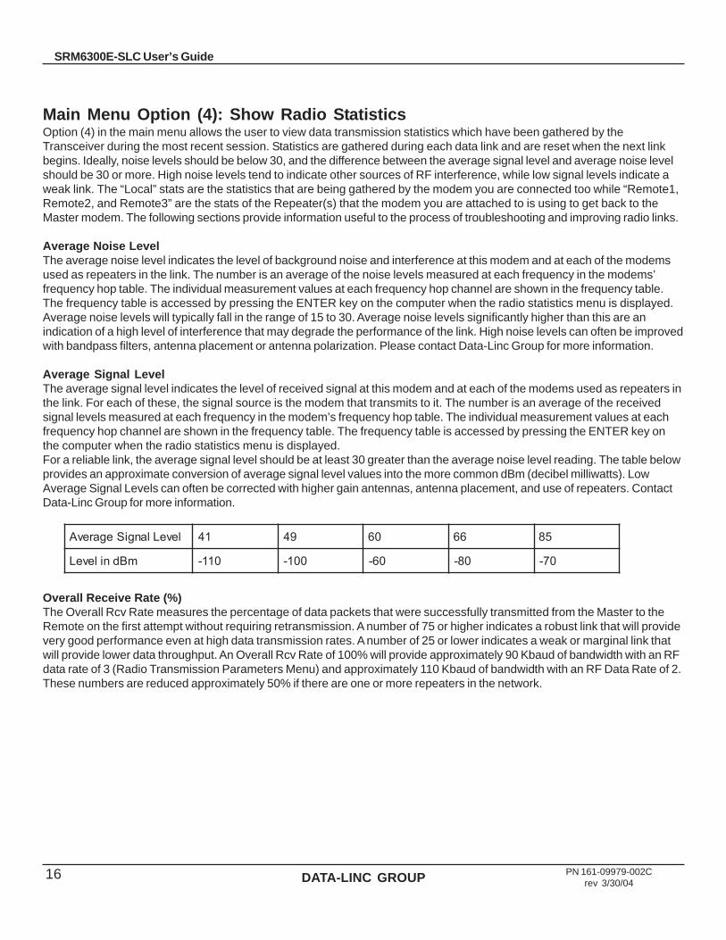
Average Signal LevelThe average signal level indicates the level of received signal at this modem and at each of the modems used as repeaters inthe link. For each of these, the signal source is the modem that transmits to it. The number is an average of the receivedsignal levels measured at each frequency in the modem’s frequency hop table. The individual measurement values at eachfrequency hop channel are shown in the frequency table. The frequency table is accessed by pressing the ENTER key onthe computer when the radio statistics menu is displayed.For a reliable link, the average signal level should be at least 30 greater than the average noise level reading. The table belowprovides an approximate conversion of average signal level values into the more common dBm (decibel milliwatts). LowAverage Signal Levels can often be corrected with higher gain antennas, antenna placement, and use of repeaters. ContactData-Linc Group for more information.
Overall Receive Rate (%)The Overall Rcv Rate measures the percentage of data packets that were successfully transmitted from the Master to theRemote on the first attempt without requiring retransmission. A number of 75 or higher indicates a robust link that will providevery good performance even at high data transmission rates. A number of 25 or lower indicates a weak or marginal link thatwill provide lower data throughput. An Overall Rcv Rate of 100% will provide approximately 90 Kbaud of bandwidth with an RFdata rate of 3 (Radio Transmission Parameters Menu) and approximately 110 Kbaud of bandwidth with an RF Data Rate of 2.These numbers are reduced approximately 50% if there are one or more repeaters in the network.
leveLlangiSegarevA 14 94 06 66 58
mBdnileveL 011- 001- 06- 08- 07-
DATA-LINC GROUP 17
SRM6300E-SLC User’s Guide
PN 161-09979-002Crev 3/30/04
Number of DisconnectsIf, during the course of performing a link test, the link between the master and the slave is broken, and the radios lose carrierdetect, the occurrence is recorded in the Number of Disconnects value. The value indicates the total number of disconnectsthat have occurred from the time the link test started until the radio was put into config mode. Under normal operatingconditions, the number of disconnects should be 0. One or more disconnects may indicate a very weak link, the presence ofsevere interference problems or loss of DC power to the Master or Repeater if one is present.
Note: A remote and/or repeater will record a disconnect if the system master is placed into configuration modeor has power interrupted while the remote and/or repeater is linked to the master.
Radio TemperatureThe radio temperature value is the current operating temperature of the radio in degrees C (Celsius.) For proper operation,SRM6300E-SLC radio modems must be in the range of –400 to 750 C.
Multi-Point OperationIn a multi-point system, a radio modem designated as a master is able to simultaneously be in communication withnumerous remotes. In its simplest form, a multi-point network functions with the Master broadcasting its messages to allremotes and the Remotes responding to the Master as appropriate.
Traditionally, a multi-point network is used in applications where data is collected from many instruments and reported backto one central site. As such, the architecture of such a system is completely different from point-to-point applications. Thetheoretical maximum number of remotes that can be configured into a multi-point network is a function of the data throughputneeded from each of the remotes. For example, if the network will be polling remotes once a day to retrieve sparse data,several hundred remotes could be configured to a single master. If, on the other hand, each remote will be transmitting dataat greater levels then fewer remotes may be connected to the Master (the overall system will be closer to capacity with fewerremotes).
The theoretical limit of a multi-point system is influenced by the following parameters:
• Size of the blocks of data— the longer the data blocks the greater the system capacity• Throughput• The amount of contention between remotes• Use of repeaters— a single repeater in a multi-point network will decrease overall system capacity by 50%; more than
one repeater does not further decrease network capacity
DATA-LINC GROUP18 PN 161-09979-002Crev 3/30/04
SRM6300E-SLC User’s Guide
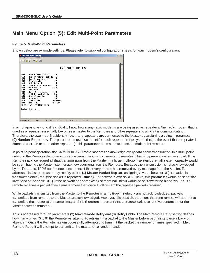
Main Menu Option (5): Edit Multi-Point Parameters
Figure 5: Multi-Point Parameters
Shown below are example settings. Please refer to supplied configuration sheets for your modem’s configuration.
In a multi-point network, it is critical to know how many radio modems are being used as repeaters. Any radio modem that isused as a repeater essentially becomes a master to the Remotes and other repeaters to which it is communicating.Therefore, the user must first identify how many repeaters are connected to the Master by assigning a value in parameter(0) Number Repeaters. This parameter must also be set for each repeater in the system (i.e., in the event that a repeater isconnected to one or more other repeaters). This parameter does need to be set for multi-point remotes.
In point-to-point operation, the SRM6300E-SLC radio modems acknowledge every data packet transmitted. In a multi-pointnetwork, the Remotes do not acknowledge transmissions from master to remotes. This is to prevent system overload. If theRemotes acknowledged all data transmissions from the Master in a large multi-point system, then all system capacity wouldbe spent having the Master listen for acknowledgments from the Remotes. Because the transmission is not acknowledgedby the Remotes, 100% confidence does not exist that every remote has received every message from the Master. Toaddress this issue the user may modify option (1) Master Packet Repeat, assigning a value between 0 (the packet istransmitted once) to 9 (the packet is repeated 9 times). For networks with solid RF links, this parameter would be set at thelower end of the scale (0-1). If the network has some weak or marginal links it would be set toward the higher values. If aremote receives a packet from a master more than once it will discard the repeated packets received.
While packets transmitted from the Master to the Remotes in a multi-point network are not acknowledged, packetstransmitted from remotes to the Master are acknowledged. However, it is possible that more than one remote will attempt totransmit to the master at the same time, and it is therefore important that a protocol exists to resolve contention for theMaster between remotes.
This is addressed through parameters (2) Max Remote Retry and (3) Retry Odds. The Max Remote Retry setting defineshow many times (0 to 9) the Remote will attempt to retransmit a packet to the Master before beginning to use a back-offalgorithm. Once the Remote has unsuccessfully attempted to transmit the packet the number of times specified in MaxRemote Retry it will attempt to transmit to the master on a random basis.

DATA-LINC GROUP 19
SRM6300E-SLC User’s Guide
PN 161-09979-002Crev 3/30/04
The Retry Odds parameter determines the probability that the Remote will attempt to retransmit the packet to the Master; alow setting will assign low odds to the Remote attempting to transmit and conversely a high setting will assign high odds. Anexample of how this parameter might be used would be when considering two different remotes in a multi-point network, oneclose in with a strong RF link and the other far from the Master with a weak link. It may be desirable to assign a higher RetryOdd to the Remote with the weaker link to give it a better chance of competing with the closer Remote for the Master’sattention.
Another parameter in a multi-point network is (4) DTR Connect. This setting is not applicable in the SRM6300E-SLC’s andshould not be changed from a factory default of 0.
The Repeater’s hopping pattern must also be set in a multi-point network; this is accomplished with parameter (5) RepeaterFrequency. Setting this parameter is in contrast with point-to-point mode where the Repeater automatically uses theMaster’s hopping pattern. The Repeater may be programmed to either use the Master’s hopping pattern selection (0) or itsown selection (1).
Option (6) NetWork ID allows multi-point networks to be established without the use of the Call Book. If the NetWork ID isset to any value lower than the default (255) the Remotes in the multi-point network will communicate with the first multi-pointmaster or repeater heard with the same NetWork ID. When the NetWork ID is used multi-point masters and repeaters maybe replaced without reprogramming all of the Remotes in the network. In addition, this allows a remote to establishcommunications with different masters (though not at the same time) without having the call book numbers in the Call Book.This is very useful in mobile multi-point applications.
(8) Multi Master Synch is reserved for multi-point applications with concentrations of master units where it is necessary to reduce interference between the Masters. Please contact the factory for more information on the use of this feature.
(9) 1PPS Enable/DelayThis setting is not applicable to the SRM6300E-SLC and should not be changed from the factory default of 255.
(A) Remote/RepeaterThe Remote/Repeater mode allows a SRM6300E-SLC in a multi-point system to simultaneously act as a remote and arepeater. When in this mode a SRM6300E-SLC will repeat any packets sent from a master as well as send them out theEthernet port. This gives a SRM6300E-SLC set as a repeater to act as a remote at the same time. 0 disables this mode,1 enables it. For this feature to work, the modem must be configured as a point-to-multipoint repeater.
(B) DiagnosticsThe SRM6300E-SLC has the ability to run a diagnostic program while in normal operations. Contact the factory foradditional information.
(C) SubNet IDThe default setting is “Disabled.” Please see the SubNet ID section of this manual.
(D) Radio IDUsed with the Diagnostics. Contact the factory for additional information.

DATA-LINC GROUP20 PN 161-09979-002Crev 3/30/04
SRM6300E-SLC User’s Guide
SubNet IDThe SRM6300E-SLC series modems offer a SubNet ID system for use in multi-point networks using Network ID. This featureallows the users to dictate what path a given repeater or remote will use to achieve a link to the network Master. Forexample, if a remote modem in a given network has line of sight to the network Master and one or more repeaters, but onlyone repeater is close to that Remote, SubNet ID can be used to link that Master with the proper Repeater only.
Note: This feature can only be used in networks using Network ID with one or more repeaters.
There are two components to SubNet ID. The first is the Xmit (transmit) SubNet ID, and the second is Rcv (receive) SubNetID. The Xmit SubNet ID is used only by repeaters and is the ID that a repeater sends out when sending data to otherrepeaters or remotes. The Rcv SubNet ID is the ID that repeaters or remotes look for to receive data.
Note: The master is not affected by these settings. Only repeaters and remotes use these settings. Remotes onlyuse Rcv SubNet ID.
Modem configurations are as follows (see diagram 1 below):
Master No setting used
Repeaters Any repeater that should be linked directly to the Master should have the Rcv SubNet ID set to 0. Anyrepeater using another repeater as its link, needs the Rcv SubNet ID set to the Xmit SubNet ID of thatRepeater. The Xmit SubNet ID can be set to anything from 1 to E.
Remotes Any remote that should be linked directly to the Master should have the Rcv SubNet ID set to 0. Anyremote using a repeater as its link should have the Rcv SubNet ID set to the Xmit SubNet ID of thatRepeater.
Diagram 1
LANLink
In
Out
Coll
RFPower
Link
Out
In
Power
Ethernet Radio Modem
Reset/Confg
+V-V
10 to 28 VDC
10BaseT
Use A or B for Lan Link
Radio Configuration
OE
A B
LANLink
In
OutColl
RFPower
Link
Out
In
Power
Ethernet Radio Modem
Reset/Confg
+V-V
10 to 28 VDC
10BaseT
Use A or B for Lan Link
Radio Configuration
OE
A B
LANLink
In
Out
Coll
RFPower
Link
Out
In
Power
Ethernet Radio Modem
Reset/Confg
+V-V
10 to 28 VDC
10BaseT
Use A or B for Lan Link
Radio Configuration
OE
A B
LANLink
In
Out
Coll
RFPowerLink
OutIn
Power
Ethernet Radio Modem
Reset/Confg
+V-V
10 to 28 VDC
10BaseT
Use A or B for Lan Link
Radio Configuration
OE
A B
LANLink
In
Out
Coll
RFPower
Link
Out
In
Power
Ethernet Radio Modem
Reset/Confg
+V-V
10 to 28 VDC
10BaseT
Use A or B for Lan Link
Radio Configuration
OE
A BLAN
LinkIn
Out
Coll
RFPower
Link
Out
In
Power
Ethernet Radio Modem
Reset/Confg
+V-V
10 to 28 VDC
10BaseT
Use A or B for Lan Link
Radio Configuration
OE
A B
LANLink
In
Out
Coll
RFPowerLink
OutIn
Power
Ethernet Radio Modem
Reset/Confg
+V-V
10 to 28 VDC
10BaseT
Use A or B for Lan Link
Radio Configuration
OE
A B
Rcv = 0Xmit not set
Remote 1
Xmit/Rcv not setRcv = 0Xmit =1
Rcv = 1Xmit =2
Rcv not setXmit not set
Rcv = 2Xmit not set
Rcv = 1Xmit not set
Repeater 1
Remote 4
Repeater 2Master
Remote 2 Remote 3
DATA-LINC GROUP 21
SRM6300E-SLC User’s Guide
PN 161-09979-002Crev 3/30/04
Main Menu Option (8): PasswordCaution: If the password feature is enabled and you cannot remember the password, the radio modem will have to bereturned to Data-Linc Group to have the password disabled. Use with caution.
Option (8) in the Main Menu allows the user to set a password which will prevent unauthorized users to change theconfiguration of the modem.
Setting a PasswordTo enable the Password feature choose (8) from the Main Menu. You will be prompted with “New PW? (<esc> to exit)
To back out of the process and not enable the password, hit escape. To set a password type in exactly 4characters. At any point in the process you can cancel by hitting the escape key. Once the 4 characters have been enteredyou will be prompted with “<enter> to accept, <esc> to quit”.
At this point, if you wish to accept the password entered and enable the feature, press the enter key. The password that youhave chosen is displayed on the line above (please note that the password is case sensitive). To quit the process and notenable the password press escape.
Changing a PasswordOnce the password feature has been enabled it is possible to change to a new password. To enter a new password select(8) from the Main Menu. You will be prompted with “Enter Security Code”. Enter the current password. Once the passwordhas been entered correctly (it is case sensitive) you will be prompted to enter the new password. At any point this processmay be cancelled by pressing escape.
Disabling PasswordThe process to disable the password is similar to the process to change the password. However, when prompted to enter thenew password, the following procedure needs to be followed:
1. Hold the “Alt” key down and using the number key pad (not the numbers across the top of the key board) type “0255”2. Release the “Alt” key3. Repeat steps 1 and 2 three more times (this will enter 0255 a total of four times).4. You will be prompted with “<Enter> to accept, <esc> to quit
5. Hit the “Enter” key to disable the password or hit the escape key to keep the password
DATA-LINC GROUP22 PN 161-09979-002Crev 3/30/04
SRM6300E-SLC User’s Guide
SRM6300E-SLC Location SelectionPlacement of your SRM6300E-SLC is likely to have a significant impact on its performance. In general, the rule of thumb withthe SRM6300E-SLC is that the higher the placement of the antenna the better the communication. In practice you shouldalso place the radio modem itself away from computers, telephones, answering machines, and other similar equipment. Toimprove the data link, Data-Linc Group offers directional and omni directional antennas with cable lengths ranging from 10 to250 feet.
When using an external antenna, placement of that antenna is critical to a solid data link. Other antennas in close proximityare a potential source of interference. It is also possible that slight adjustments in antenna placement (as little as 2 feet) willsolve noise problems. In extreme cases, such as when the radio modem is located close to pager or cellular telephonetransmission towers, Data-Linc offers a band pass filter to reduce the out of band noise.
Using an External AntennaIn certain circumstances it may be desirable to extend the range of the SRM6300E-SLC radio modem by using an externalantenna in place of the standard whip antenna. The radio modem is equipped with a standard SMA external jack. This allowsthe use of a directional Yagi or omni directional antennae kits provided by Data-Linc Group.
The use of an external antenna may radically improve the results obtained with SRM6300E-SLC radio modems. It isimperative to obtain line-of-sight with the antennas, and changes in placement height of as few as a couple of feet may makethe difference between no link and one that is solid and reliable.
Data-Linc Group offers a variety of omni directional and directional external antennae, with both bracket and magneticmounts. These antennas allow versatility in the SRM6300E-SLC’s deployment, extending its range and allowing it to getaround obstructions.
If external directional antennas are used, FCC regulations concerning effective radiated power limitations must be followed.
Caution: Any antenna placed outdoors must be properly grounded. It is required by FCC regulations that qualifiedpersonnel experienced in antenna installation and familiar with local codes and regulations complete the antennainstallation. It is also required by FCC regulations that only approved antennas be used. Use extreme caution wheninstalling antennae and follow all instructions included with the antennas.
The use of external antennae subjects the radio modem to greater exposure to direct lightning strikes. It is stronglyrecommended that a lightning arrestor be used on all outdoor antenna installations.
DATA-LINC GROUP 23
SRM6300E-SLC User’s Guide
PN 161-09979-002Crev 3/30/04
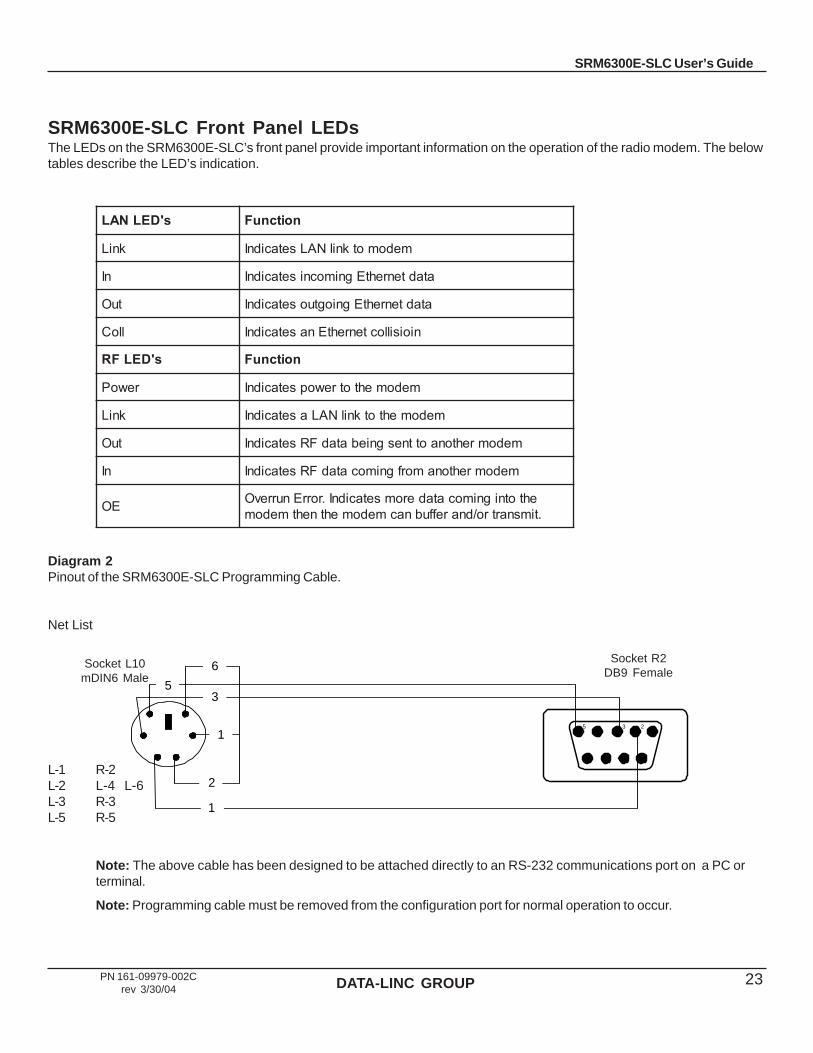
SRM6300E-SLC Front Panel LEDsThe LEDs on the SRM6300E-SLC’s front panel provide important information on the operation of the radio modem. The belowtables describe the LED’s indication.
Diagram 2Pinout of the SRM6300E-SLC Programming Cable.
Net List
L-1 R-2L-2 L-4 L-6L-3 R-3L-5 R-5
Note: The above cable has been designed to be attached directly to an RS-232 communications port on a PC orterminal.
Note: Programming cable must be removed from the configuration port for normal operation to occur.
Socket L10mDIN6 Male
Socket R2DB9 Female
5 3 2
1
2
1
3
6
5
s'DELNAL noitcnuF
kniL medomotknilNALsetacidnI
nI atadtenrehtEgnimocnisetacidnI
tuO atadtenrehtEgniogtuosetacidnI
lloC nioisilloctenrehtEnasetacidnI
s'DELFR noitcnuF
rewoP medomehtotrewopsetacidnI
kniL medomehtotknilNALasetacidnI
tuO medomrehtonaottnesgniebatadFRsetacidnI
nI medomrehtonamorfgnimocatadFRsetacidnI
EO ehtotnignimocataderomsetacidnI.rorrEnurrevO.timsnartro/dnareffubnacmedomehtnehtmedom

DATA-LINC GROUP24 PN 161-09979-002Crev 3/30/04
SRM6300E-SLC User’s Guide
Diagram 3The locations of the jumpers and switches of the SRM6300E-SLC.
SW 1 is the 10 Base-Tcontroller switches
SW 3 is the 10 Base-Tcrossover switchLeft = StraightRight = Crossover
SW 2 is the configuremenu switch used inconjunction with theprogramming cable
Wide Range Module
24v Module
1 Com
pr2 F
ilter3 A
ccm4 B
aud 25 B
aud 16 B
aud 0
COPYRIGHT 2002
U2
U6 C3
C7
D1
C1
C26U
3
C4C6
U4
U5
SW
1
VR1
C28
RN2
R2
C2
C8
C5
R17
L5L6
C32
X2
P6
P5 LE
D1
C20 T1
LED
2S
W2
R1
X1
R7
R6U1
L1
R5
R3
SW
3
C14
P2
C9
RN
1
P1
C22
R4
C10
LED
3
C33
C16
C21 C15
P3
C24
R16
DP
4
DP
1
C12
C18
DP
3
P4
L3
C23
DP
2
R9R8
R11
R10
R12
C17
R14
R13
R15C
19
C11
C13
L2
L4
C34
C25
C31 D2M1
C30
VR2
F1
C29
C27
VR3
Wide Range Module
24v Module
1 Com
pr2 F
ilter3 A
ccm4 B
aud 25 B
aud 16 B
aud 0
COPYRIGHT 2002

DATA-LINC GROUP 25
SRM6300E-SLC User’s Guide
PN 161-09979-002Crev 3/30/04
Sample Data Communication LinksThe SRM6300E-SLC’s versatility allows data communication links to be established using a variety of differentconfigurations. This, in turn, makes it possible to extend the range of the SRM6300E-SLC and get around obstacles.
Diagram 4 shows the most common and straightforward link, a master communicating to a remote in a dedicated link.
Diagram 4
Diagram 5 depicts how a link might be set up using a repeater. The Repeater may be sitting on a hilltop or other elevatedstructure to link the Master to the Remote. In this setup it may be desirable to use an external omni directional antenna onthe Repeater; to extend the range Yagi antennas could be used on either or both of the Master and Remote.
Diagram 5
When a repeater is used the throughput is cut in half. Adding a second repeater (or more) ‘does not further reduce thethroughput, however it does increase the latency.
Point-to-PointMaster
Point-to-PointRepeater
Point-to-PointRemote
Workstation
LANLink
In
Out
Coll
RFPower
Link
Out
In
Power
Ethernet Radio Modem
Reset/Confg
+V-V
10 to 28 VDC
10BaseT
Use A or B for Lan Link
Radio Configuration
OE
A B
ALLEN-BRADLEY
SLC5/0X CPUFORCE
RS232
RUN
FLT
BATT
RUN REM PROG
ANT
ANT
10Base-T
SRM6200E-SLCPowerRF Carrier
RF OutRF In
ANT
ANT
Lan Link
Lan InLan OutCollision
Buffer
ConfigPort
Power
DATA-LINC GROUP
+-
(425) 882-2206
R/C
Workstation
LAN
LinkIn
Out
Coll
RFPower
Link
Out
In
Power
Ethernet Radio Modem
Reset/Confg
+V-V
10 to 28 VDC
10BaseT
Use A or B for Lan Link
Radio Configuration
OE
A BLAN
LinkIn
Out
Coll
RFPower
Link
Out
In
Power
Ethernet Radio Modem
Reset/Confg
+V-V
10 to 28 VDC
10BaseT
Use A or B for Lan Link
Radio Configuration
OE
A B
ALLEN-BRADLEY
SLC5/0X CPUFORCE
RS232
RUN
FLT
BATT
RUN REM PROG
ANT
ANT
10Base-T
SRM6200E-SLCPowerRF CarrierRF OutRF In
ANT
ANT
Lan LinkLan InLan OutCollision
Buffer
ConfigPort
Power
DATA-LINC GROUP
+-
(425) 882-2206
R/C

DATA-LINC GROUP26 PN 161-09979-002Crev 3/30/04
SRM6300E-SLC User’s Guide
Diagram 6 depicts an example of a point-to-multi-point system. In this example any data sent from the Master is broadcastto all four remotes. One remote is receiving data directly from the Master, two others are connected through a repeater whilethe last one is getting its data from a repeater configured as a repeater/remote.
Diagram 6
Point-to-Multi-PointMaster
Point-to-Multi-PointRepeater
Point-to-Multi-PointRemote
Point-to-Multi-PointRemote
Point-to-Mulit-pointRemote
Point-to-Multi-PointRepeater/Remote
W orkstation
L ANL ink
In
O utC oll
RFPo w e r
Lin k
Ou t
In
P ow er
Etherne t R adio M odem
Re s e t/Co n fg
+V-V
10 to 28 VD C
10B ase T
U se A or B for L an Link
R ad io Co n fig ura tio n
O E
A B
L ANLin k
In
Ou t
Co ll
R FP ow er
L in k
O ut
In
Po w e r
E the rnet R a dio M ode m
R e s e t/C on fg
+V-V
10 to 28 VD C
10BaseT
U se A o r B fo r L an Lin k
R ad io C on fig u ra tio n
OE
A B
A LLEN-B R ADLEY
SL C5 /0 X CPUF O RCE
RS 232
RUN
F LT
BA TT
RUN RE M P ROG
ANT
ANT
10Base-T
SRM6200E-SLCPow erR F Carrie rR F O utR F In
ANT
ANT
Lan LinkLan InLan O utC ollision
Buffer
C onfigPort
Pow er
DA TA-L INC GROUP
+-
(425) 882 -2206
R/
C
A LLEN-BR AD LEY
SLC 5/0X CPUF ORCE
RS232
RUN
F LT
B A TT
RUN REM P RO G
ANT
ANT
10Base-T
SRM6200E-SLCPow erRF Carr ie rRF O utRF In
ANT
ANT
Lan L inkLan InLan O ut
Co llis ion
Buffe r
ConfigPort
Pow er
DA TA -LINC G RO UP
+-
(425 ) 882-2206
R/
C
A LLEN-B R ADLEY
SL C5 /0 X CPUF O RCE
RS 232
RUN
F LT
BA TT
RUN RE M P ROG
ANT
ANT
10Base-T
SRM6200E-SLCPow erR F Carrie rR F O utR F In
ANT
ANT
Lan LinkLan InLan O ut
C ollision
Buffer
C onfigPort
Pow er
DA TA-L INC GROUP
+-
(425 ) 882 -2206
R/
C
A LLEN-B RAD LEY
SLC 5/0 X CPUF O RCE
RS232
RUN
F LT
B A TT
RUN RE M P RO G
ANT
ANT
10Base-T
SRM6200E-SLCPow erRF Carr ie rRF O utRF In
ANT
ANT
Lan L inkLan InLan O ut
Co llis ion
Buffer
ConfigPort
Pow er
DA TA -LINC G RO UP
+-
(425 ) 882-2206
R/C

DATA-LINC GROUP 27
SRM6300E-SLC User’s Guide
PN 161-09979-002Crev 3/30/04
Technical Specifications
stnemeriuqeRrewoP nICDV82ot01
rewoPgnitarepO muminimsttaw2,xaMsttaw8
ycneuqerFgnitarepO )deriuqeresneciletisCCFon(dnabMSIzHM829-209
erutarepmeTgnitarepOegnaR 04- 0 761ot 0 04-(F 0 57ot 0 )C
etaRataDFR spbk881ro441
egnaRFR@thgis-fo-enilhtiw)mk04(selim52:detaR
thgis-fo-enilhtiw)mk65(selim53;02+esion>langissnoitidnoclamitporednu
rewoptuptuoFR )stnemercnittaw1.0noelbatceles(ttaW0.1ot1.0
tuphguorhTataDmumixaM )edomtniop-ot-tniopni(spbk011
rotcennoCannetnA elameFAMSdaerhTdradnatS
sedoMgnitarepOtnioP-ot-tnioP
tnioP-itluM-ot-tnioPdenibmocetomeR/retaepeR,retaepeR
snoisnemiDerusolcnE tolskcar6471elgniS
thgieW )gk43.(bl7.

DATA-LINC GROUP28 PN 161-09979-002Crev 3/30/04
SRM6300E-SLC User’s Guide
Troubleshooting“I have two radio modems, one configured as a master and the other as a remote. When they are plugged in, theLEDs indicate they are receiving power, and yet they will not connect. Why not?”
There are several reasons why this may occur:
1. No antenna attached to the Modem.
2. The radio modems are not in each other’s Call Books.
3. The number of the Remote is in the Master’s Call Book, but the Master’s menu is not set to call that number.
4. The Master is set to Call All and a setting of 000-0000 precedes the number of the Radio Modem with which you are trying to communicate.
“I am able to link to a remote unit within line of sight when the SRM6300E-SLC I have is outside. However, assoon as I walk inside with it I lose the link, even if I place the Radio Modem by the window which faces theRemote unit.”
Many modern buildings use energy efficient glass that wreaks havoc on RF signals. This glass contains a metal film that isvery effective in blocking all radio waves. If your situation is as described above the preferable solution is to install an antennaoutdoors.
“I have several radio modems set up to communicate with each other in a point-to-multi-point mode, yet they arenot establishing contact.”
In a multi-point system there are two critical parameters which must be set correctly to establish a communications link:
1. The Remote’s Call Book must contain the Call Book Number or Network ID of the Master and/or Repeater(s) towhich it will be communicating.
2. All radios must be set to run at the same RF data rate. Remote modems must match the Masters RF datarate.
“In bench testing several units in a multi-point system, it appears that they are not communicating through themulti-point repeater. When all units are powered the remotes’ Carrier Detect lights are on, indicating aconnection, yet when I unplug the repeater those remotes set up to communicate through that repeater remainconnected.”
In a multi-point system a remote will attempt to communicate with any master or repeater (which looks like a master in amulti-point system) that is in its Call Book. Therefore, it may be that the Remotes are communicating with the Repeaterwhen it is powered, and when it is unplugged they are establishing a link with the Master. To test whether or not this is whatis occurring, go into the Call Book of the Remotes which are set up to communicate through the Repeater and remove theMaster’s Call Book Number. When all units are powered the Remotes’ Carrier Detect lights should be green, when theRepeater is unplugged the Remotes should lose contact and Carrier Detect should turn off.

DATA-LINC GROUP 29
SRM6300E-SLC User’s Guide
PN 161-09979-002Crev 3/30/04
Technical SupportData-Linc Group maintains a fully trained staff of service personnel who are capable of providing complete productassistance. They can provide you with technical, application and troubleshooting, spare parts and warranty assistance. Ourtechnical staff is based in Bellevue, Washington USA and may be reached at (425) 882-2206 or [email protected]
Product WarrantyData-Linc Group warrants equipment of its own manufacture to be free from defects in material and workmanship for one yearfrom date of shipment to original user. Data-Linc Group will replace or repair, at our option, any part found to be defective.Buyer must return any part claimed defective to Data-Linc Group, transportation prepaid.
Return Material AuthorizationIf a part needs to be sent to the factory for repair, contact Data-Linc Group’s corporate office and request a Return MaterialAuthorization (RMA) number. The RMA number identifies the part and the owner and must be included with the part whenshipped to the factory.
Contact InformationCorporate Office Data-Linc Group
3535 Factoria Blvd. SESuite 100Bellevue, Washington 98006 USA
Telephone: (425) 882-2206Fax: (425) 867-0865E-mail: [email protected] site: www.data-linc.com