
SRI KRISHNA INSTITUTE OF TECHNOLOGY, BANGALORE …
23
BE-4-ME-SKIT-Ph5b1-F02-V2.0 LABORATORY PLAN - CAY 2019-20 SRI KRISHNA INSTITUTE OF TECHNOLOGY, BANGALORE COURSE PLAN Academic Year 2019-20 Program: BE – MECHANICAL ENGINEERING Semester : 4 Course Code: 18MEL48B Course Title: FOUNDRY FORGING and WELDING LAB Credit / L-T-P: 2 / 0-2-2 Total Contact Hours: 36 Course Plan Author: Dinesh P/CHANDRAIAH M T Academic Evaluation and Monitoring Cell No. 29, Chimney hills, Hesaraghatta Road, Chikkabanavara BANGALORE-560090, KARNATAKA , INDIA Phone / Fax :+91-08023721315/23721477, Web: www.skit.org.in 18MEL48B Copyright ©2017. cAAS. All rights reserved. Page # 1 / 23 Ref No:
Transcript of SRI KRISHNA INSTITUTE OF TECHNOLOGY, BANGALORE …

BE-4-ME-SKIT-Ph5b1-F02-V2.0LABORATORY PLAN - CAY 2019-20
SRI KRISHNA INSTITUTE OF TECHNOLOGY, BANGALORE
COURSE PLAN
Academic Year 2019-20
Program: BE – MECHANICAL ENGINEERING
Semester : 4
Course Code: 18MEL48B
Course Title: FOUNDRY FORGING and WELDING LAB
Credit / L-T-P: 2 / 0-2-2
Total Contact Hours: 36
Course Plan Author: Dinesh P/CHANDRAIAH M T
Academic Evaluation and Monitoring Cell
No. 29, Chimney hills, Hesaraghatta Road, ChikkabanavaraBANGALORE-560090, KARNATAKA , INDIA
Phone / Fax :+91-08023721315/23721477, Web: www.skit.org.in
18MEL48B Copyright ©2017. cAAS. All rights reserved.Page # 1 / 23
Ref No:

BE-4-ME-SKIT-Ph5b1-F02-V2.0LABORATORY PLAN - CAY 2019-20
Table of Contents
FOUNDRY FORGING and WELDING LAB...........................................................118MEL48B : FOUNDRY FORGING and WELDING LAB............................4
A. LABORATORY INFORMATION.................................................................................................41. Lab Overview............................................................................................................................................................ 42. Lab Content............................................................................................................................................................... 43. Lab Material............................................................................................................................................................... 44. Lab Prerequisites:.................................................................................................................................................. 45. General Instructions.............................................................................................................................................56. Lab Specific Instructions..................................................................................................................................5
B. OBE PARAMETERS...........................................................................................................................51. Lab / Course Outcomes...................................................................................................................................52. Lab Applications....................................................................................................................................................63. Articulation Matrix.................................................................................................................................................64. Mapping Justification..........................................................................................................................................65. Curricular Gap and Content...........................................................................................................................76. Content Beyond Syllabus...............................................................................................................................8
C. COURSE ASSESSMENT................................................................................................................81. Course Coverage...................................................................................................................................................82. Continuous Internal Assessment (CIA)...................................................................................................8
D. EXPERIMENTS.....................................................................................................................................9Experiment 01 : Compression strength test for molding sand..................................................9Experiment 02 : shear strength test for molding sand...................................................................11Experiment 03 : tensile strength test for molding sand...............................................................13Experiment 04 : Permeability test................................................................................................................14Experiment 05 : Clay content determination test for molding sand...................................17Experiment 06: Sieve analysis test..............................................................................................................18Experiment 06:FOUNDRY PRACTICE.......................................................................................................20 Foundry practice of solid pattern...............................................................................................................20Experiment 07:FOUNDRY PRACTICE.........................................................................................................21 Foundry practice of split pattern pattern...............................................................................................21Experiment 08:FOUNDRY PRACTICE........................................................................................................22 Foundry practice of solid pattern................................................................................................................22Experiment 09:FOUNDRY MODELS...........................................................................................................23 Preparation of forging models......................................................................................................................23Experiment 10:FOUNDRY MODELS............................................................................................................24 Preparation of forging models......................................................................................................................24
Note : Remove “Table of Content” before including in CP Book Each Laboratory Plan shall be printed and made into a book with cover page Blooms Level in all sections match with A.2, only if you plan to teach / learn at higher levels
18MEL48B Copyright ©2017. cAAS. All rights reserved.Page # 2 / 23
BE-4-ME-SKIT-Ph5b1-F02-V2.0LABORATORY PLAN - CAY 2019-20
18MEL48B : FOUNDRY FORGING and WELDING LAB
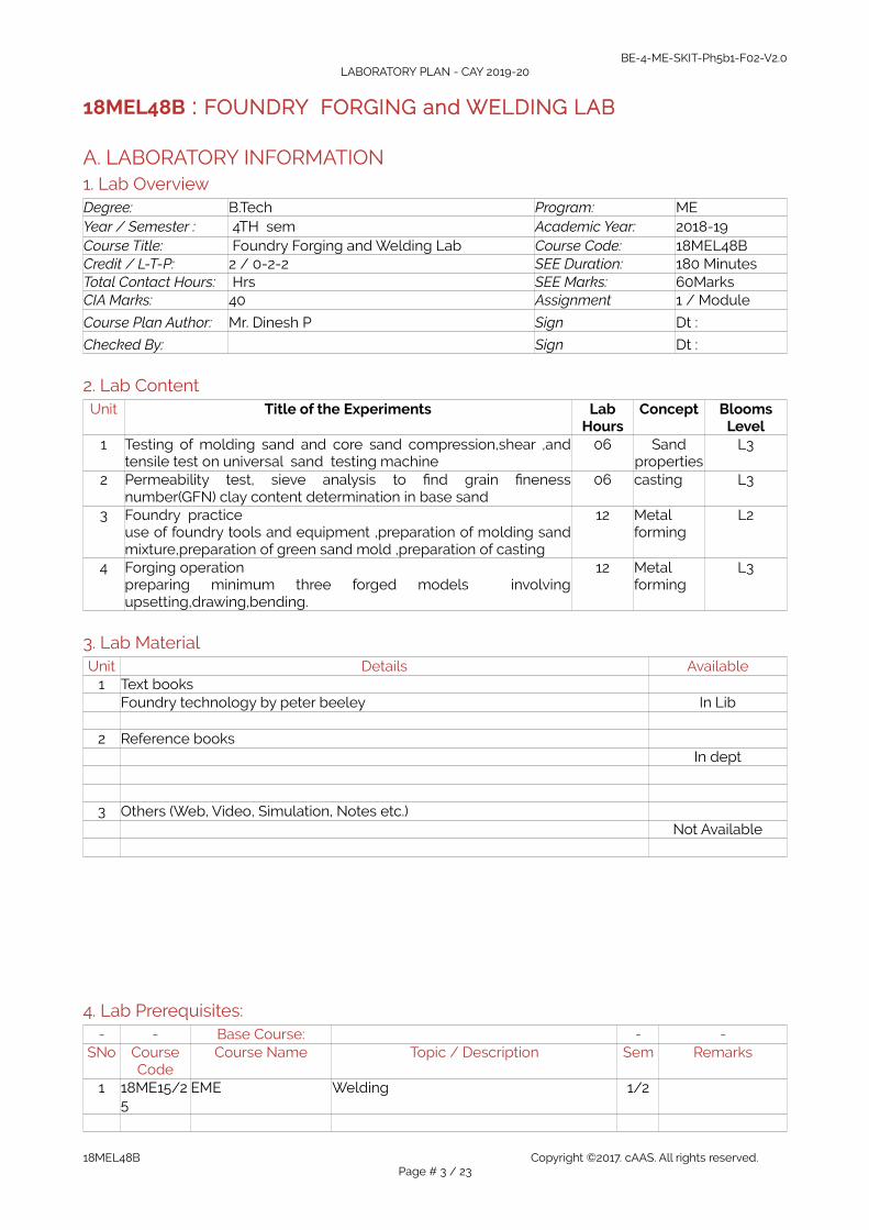
A. LABORATORY INFORMATION1. Lab OverviewDegree: B.Tech Program: MEYear / Semester : 4TH sem Academic Year: 2018-19Course Title: Foundry Forging and Welding Lab Course Code: 18MEL48BCredit / L-T-P: 2 / 0-2-2 SEE Duration: 180 MinutesTotal Contact Hours: Hrs SEE Marks: 60MarksCIA Marks: 40 Assignment 1 / Module
Course Plan Author: Mr. Dinesh P Sign Dt :
Checked By: Sign Dt :
2. Lab ContentUnit Title of the Experiments Lab
HoursConcept Blooms
Level1 Testing of molding sand and core sand compression,shear ,and
tensile test on universal sand testing machine06 Sand
propertiesL3
2 Permeability test, sieve analysis to find grain finenessnumber(GFN) clay content determination in base sand
06 casting L3
3 Foundry practiceuse of foundry tools and equipment ,preparation of molding sandmixture,preparation of green sand mold ,preparation of casting
12 Metal forming
L2
4 Forging operationpreparing minimum three forged models involvingupsetting,drawing,bending.
12 Metal forming
L3
3. Lab MaterialUnit Details Available
1 Text booksFoundry technology by peter beeley In Lib
2 Reference booksIn dept
3 Others (Web, Video, Simulation, Notes etc.)Not Available
4. Lab Prerequisites:- - Base Course: - -
SNo CourseCode
Course Name Topic / Description Sem Remarks
1 18ME15/25
EME Welding 1/2
18MEL48B Copyright ©2017. cAAS. All rights reserved.Page # 3 / 23

BE-4-ME-SKIT-Ph5b1-F02-V2.0LABORATORY PLAN - CAY 2019-20
Note: If prerequisites are not taught earlier, GAP in curriculum needs to be addressed. Include inRemarks and implement in B.5.
5. General InstructionsSNo Instructions Remarks
1 Observation book and Lab record are compulsory.2 Students should report to the concerned lab as per the time table.3 After completion of the program, certification of the concerned staff in-
charge in the observation book is necessary.4 Student should bring a notebook of 100 pages and should enter the
readings /observations into the notebook while performing the experiment.5 The record of observations along with the detailed experimental procedure
of the experiment in the Immediate last session should be submitted andcertified staff member in-charge.
6 Should attempt all problems / assignments given in the list session wise.7 It is responsibility to create a separate directory to store all the programs, so
that nobody else can read or copy.8 When the experiment is completed, should disconnect the setup made by
them, and should return all the components/instruments taken for thepurpose.
9 Any damage of the equipment or burn-out components will be viewedseriously either by putting penalty or by dismissing the total group ofstudents from the lab for the semester/year
10 Completed lab assignments should be submitted in the form of a LabRecord in which you have to write the algorithm, program code along withcomments and output for various inputs given
6. Lab Specific InstructionsSNo Specific Instructions Remarks
1234567
B. OBE PARAMETERS1. Lab / Course Outcomes
# COs Teach.Hours
Concept InstrMethod
AssessmentMethod
BloomsLevel
1 Students should be able to Conductvarious test on sand & determine sandstrength
09 Properties of sand
Demonstrate
Pratical record ,IA test
L3
2 Students should be able to Demonstratevarious skills of sand preparation andmolding
03 Sand strength
Demonstrate
Pratical record ,IA test
L2
3 Students should be able to prepare thecasting using with pattern
06 foundry Demonstrate
Pratical record ,IA test
L2
4 Students should be able to prepare thecasting without pattern
06 Metal forming
Demonstrate
Pratical record ,IA test
L2
5 Students should be able to understand 12 foundry Demonstra Pratical L3
18MEL48B Copyright ©2017. cAAS. All rights reserved.Page # 4 / 23

BE-4-ME-SKIT-Ph5b1-F02-V2.0LABORATORY PLAN - CAY 2019-20
and apply forging operations te record ,IA test
- Total 36 - - - -Note: Identify a max of 2 Concepts per unit. Write 1 CO per concept.
2. Lab ApplicationsSNo Application Area CO Level
1 Inspection methods of Moulding sand CO1 L32 Different moulding sands CO2 L23 Manufacturing industries CO3 L24 Different casting process CO4 L25 Heat treatment processes CO5 L3
Note: Write 1 or 2 applications per CO.
3. Articulation Matrix(CO – PO MAPPING)
- Course Outcomes Program Outcomes# COs PO1 PO
2PO3
PO4
PO5
PO6
PO7
PO8
PO9
PO10
PO11
PO12
Level
CO1 Students should be able toConduct various test on sand &determine sand strength
2 2 - - - - - - 2 - - - L3
CO2 Students should be able toDemonstrate various skills of sandpreparation and molding
2 - - - - - - - 2 - - - L3
CO3 Students should be able toprepare the casting using withpattern
2 - - - - - - - 2 - - - L3
CO4 Students should be able toprepare the casting withoutpattern
2 - - - - - - - 2 - - - L3
CO5 Students should be able tounderstand and apply forgingoperations
2 2 - - - - - - 2 - - - L3
AverageNote: Mention the mapping strength as 1, 2, or 3
4. Mapping JustificationMapping Mapping
LevelJustification
CO PO - -CO1 PO1 L3 Knowledge of sand preparation and pattern for making mouldCO1 PO9 L3 Individual and team work, mappingCO2 PO1 L2 Knowledge on various test on sandCO3 PO1 L2 Knowledge on preparation of casting using patternCO4 PO1 L2 Knowledge on applying forging operationCO5 PO1 L3 Knowledge to prepare casting without pattern
Note: Write justification for each CO-PO mapping.
5. Curricular Gap and ContentSNo Gap Topic Actions Planned Schedule Planned Resources Person PO Mapping
12
Note: Write Gap topics from A.4 and add others also.
18MEL48B Copyright ©2017. cAAS. All rights reserved.Page # 5 / 23

BE-4-ME-SKIT-Ph5b1-F02-V2.0LABORATORY PLAN - CAY 2019-20
6. Content Beyond SyllabusSNo Gap Topic Actions Planned Schedule Planned Resources Person PO Mapping
123
Note: Anything not covered above is included here.
C. COURSE ASSESSMENT1. Course CoverageUnit Title Teachi
ngHours
No. of question in Exam CO LevelsCIA-1 CIA-2 CIA-3 Asg-1 Asg-2 Asg-3 SEE
1 Students should be able toConduct various test on sand &determine sand strength
09 1 - - 5 - - 1 CO1 L3
2 Students should be able toDemonstrate various skills of sandpreparation and molding
03 1 - - 5 - - 1 CO2 L2
3 Students should be able toprepare the casting using withpattern
06 - 1 - - 5 - 1 CO3 L2
4 Students should be able toprepare the casting withoutpattern
06 - 1 - - 5 - 1 CO4 L2
5 Students should be able tounderstand and apply forgingoperations
12 - - 1 - - 5 1 CO5 L3
- Total 36 2 2 1 2 2 1 5 - -
Note: Write CO based on the theory course.
2. Continuous Internal Assessment (CIA)Evaluation Weightage in Marks CO Levels
CIA Exam – 1 30 CO1, CO2 L3,L3CIA Exam – 2 30 CO3, CO4 L2,L2CIA Exam – 3 30 CO5 L3
Assignment - 1 05 CO1, CO2 L3,L3Assignment - 2 05 CO3, CO4 L2,L2Assignment - 3 05 CO5 L3
Seminar - 1 05 CO1, CO2 L3,L3Seminar - 2 05 CO3, CO4 L2,L2Seminar - 3 05 CO5 L3
Other Activities – define –Slip test
- - -
Final CIA Marks 40 CO1 to Co5 L2,L3-
18MEL48B Copyright ©2017. cAAS. All rights reserved.Page # 6 / 23

BE-4-ME-SKIT-Ph5b1-F02-V2.0LABORATORY PLAN - CAY 2019-20
SNo Description Marks1 Observation and Weekly Laboratory Activities 05 Marks2 Record Writing 10 Marks for each Expt3 Internal Exam Assessment 25 Marks4 Internal Assessment 40 Marks5 SEE 60 Marks- Total 100 Marks
D. EXPERIMENTSExperiment 01 : Compression strength test for molding sand
- Experiment No.: 1 Marks DatePlanned
DateConducted
1 Title Compression strength test2 Course Outcomes The test determines the maximum Compression strength test of sand mixture3 Aim To find the green Compression strength test for different percentage of clay
and moisture4 Material Equipment
Requireduniversal sand testing machine
5 Theory, Formula,Principle, Concept
.1.Periodic tests are necessary to check the quality of foundry sand andcompression strength test is one among them.2.The constituents of moulding sand are silica sand, clay, water and other special additives.3.Clay imparts the necessary bonding strength to the moulding sand when it is mixed with water etc. bentonite.4.Compression test determines the bonding or adhesiveness power of various bonding materials in green sand.5.The green compressive strength of foundry sand is the maximum compression strength a mixture is capable of developing when it is in most condition
6 Procedure, Program,Activity, Algorithm,Pseudo Code
1. Conduct the experiment in two parts:a) Vary the clay content keeping the water content constantb) Vary the water content keeping the clay content constant2. Take weighed proportions of sand and clay and dry mix them together in aMuller for 3minutes.3. Adjust the weight of the sand to get standard specimen4. Remove the standard specimen by the stripper and place it betweenshackles which are fixed in the sand testing machine.5. Rotate the handle of the testing machine to actuate the ram. Thus, hydraulicpressure is applied continuously till the specimen raptures.6. Read the compression strength from the gauge and record the same.7. Conduct the experiment for the above said two cases and tabulate theresult.
18MEL48B Copyright ©2017. cAAS. All rights reserved.Page # 7 / 23
BE-4-ME-SKIT-Ph5b1-F02-V2.0LABORATORY PLAN - CAY 2019-20
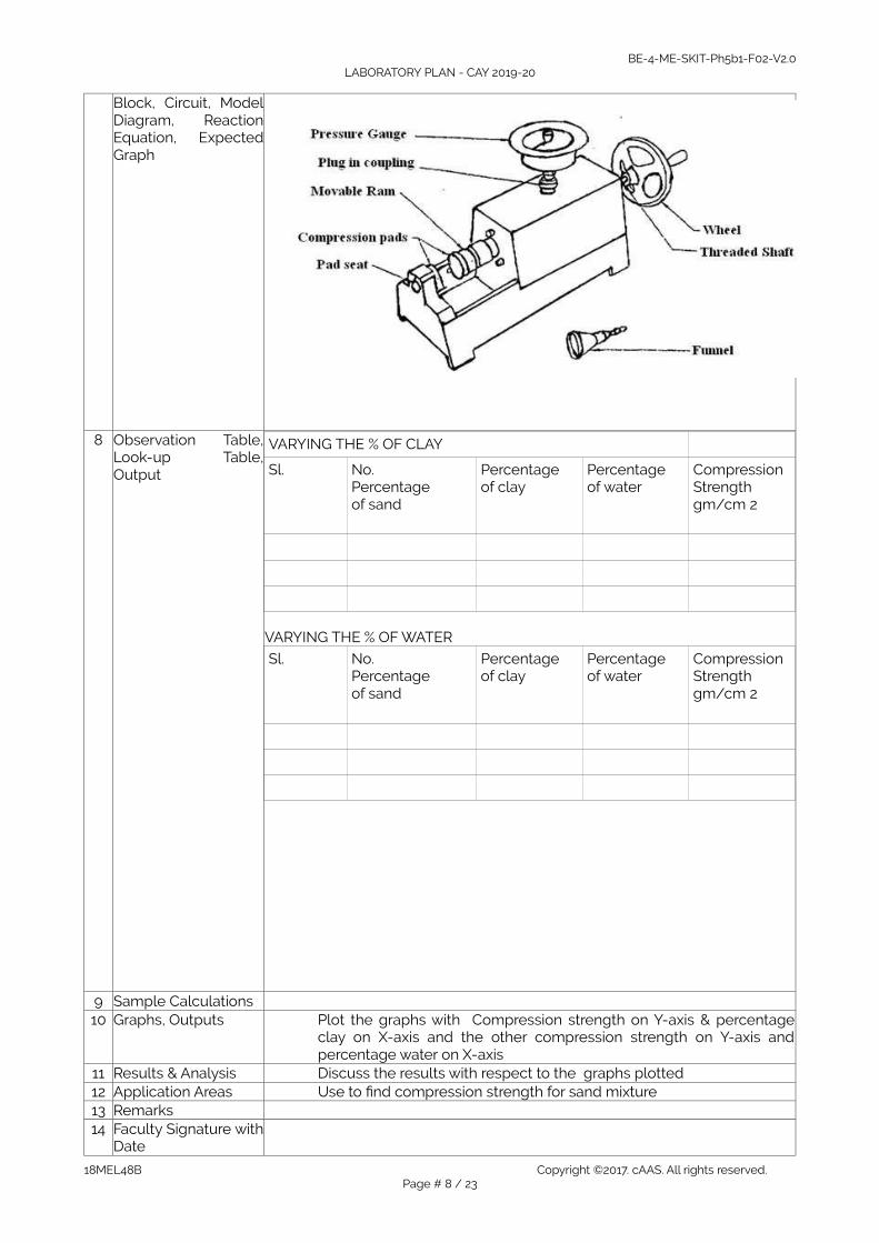
Block, Circuit, ModelDiagram, ReactionEquation, ExpectedGraph
8 Observation Table,Look-up Table,Output
VARYING THE % OF CLAY
Sl.
No.Percentageof sand
Percentageof clay
Percentageof water
Compression Strengthgm/cm 2
VARYING THE % OF WATER
Sl.
No.Percentageof sand
Percentageof clay
Percentageof water
Compression Strengthgm/cm 2
9 Sample Calculations10 Graphs, Outputs Plot the graphs with Compression strength on Y-axis & percentage
clay on X-axis and the other compression strength on Y-axis andpercentage water on X-axis
11 Results & Analysis Discuss the results with respect to the graphs plotted12 Application Areas Use to find compression strength for sand mixture 13 Remarks14 Faculty Signature with
Date
18MEL48B Copyright ©2017. cAAS. All rights reserved.Page # 8 / 23
BE-4-ME-SKIT-Ph5b1-F02-V2.0LABORATORY PLAN - CAY 2019-20
Experiment 02 : shear strength test for molding sand
- Experiment No.: 2 Marks DatePlanned
DateConducted
1 Title shear strength test for molding sand3 Aim To find shear strength test for molding sand4 Material /
EquipmentRequired
universal sand testing machine
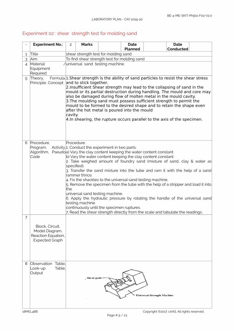
5 Theory, Formula,Principle, Concept
1.Shear strength is the ability of sand particles to resist the shear stress and to stick together.2.Insufficient Shear strength may lead to the collapsing of sand in the mould or its partial destruction during handling. The mould and core mayalso be damaged during flow of molten metal in the mould cavity.3.The moulding sand must possess sufficient strength to permit the mould to be formed to the desired shape and to retain the shape even after the hot metal is poured into the mould cavity.4.In shearing, the rupture occurs parallel to the axis of the specimen.
6 Procedure,Program, Activity,Algorithm, PseudoCode
Procedure:1. Conduct the experiment in two parts:a) Vary the clay content keeping the water content constantb) Vary the water content keeping the clay content constant2. Take weighed amount of foundry sand (mixture of sand, clay & water asspecified).3. Transfer the sand mixture into the tube and ram it with the help of a sandrammer thrice.4. Fix the shackles to the universal sand testing machine.5. Remove the specimen from the tube with the help of a stripper and load it intotheuniversal sand testing machine.6. Apply the hydraulic pressure by rotating the handle of the universal sandtesting machinecontinuously until the specimen ruptures.7. Read the shear strength directly from the scale and tabulate the readings.
7
Block, Circuit,Model Diagram,
Reaction Equation,Expected Graph
8 Observation Table,Look-up Table,Output
18MEL48B Copyright ©2017. cAAS. All rights reserved.Page # 9 / 23
BE-4-ME-SKIT-Ph5b1-F02-V2.0LABORATORY PLAN - CAY 2019-20
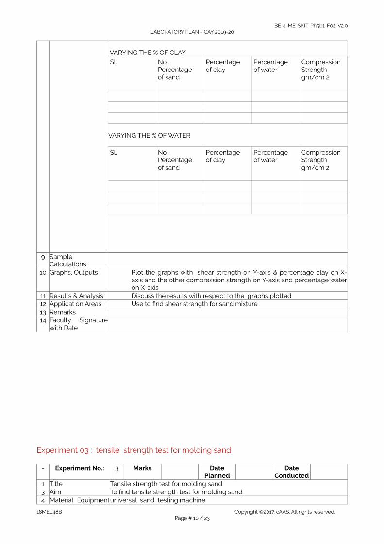
VARYING THE % OF CLAY
Sl.
No.Percentageof sand
Percentageof clay
Percentageof water
Compression Strengthgm/cm 2
VARYING THE % OF WATER
Sl.
No.Percentageof sand
Percentageof clay
Percentageof water
Compression Strengthgm/cm 2
9 SampleCalculations
10 Graphs, Outputs Plot the graphs with shear strength on Y-axis & percentage clay on X-axis and the other compression strength on Y-axis and percentage wateron X-axis
11 Results & Analysis Discuss the results with respect to the graphs plotted12 Application Areas Use to find shear strength for sand mixture 13 Remarks14 Faculty Signature
with Date
Experiment 03 : tensile strength test for molding sand
- Experiment No.: 3 Marks DatePlanned
DateConducted
1 Title Tensile strength test for molding sand3 Aim To find tensile strength test for molding sand4 Material Equipmentuniversal sand testing machine
18MEL48B Copyright ©2017. cAAS. All rights reserved.Page # 10 / 23

BE-4-ME-SKIT-Ph5b1-F02-V2.0LABORATORY PLAN - CAY 2019-20
Required5 Theory, Formula,
Principle, Concept 1.A core is compacted sand mass of a known shape.2.When a hallow casting (to have a hole through or bind) is required, a core is used in the mould or when a complex contour is required a mould is created out of cores. This core has to be properly seated in the mould on formed impressions in the sand. To form these impressions extra projections called corepoints are added on the pattern surface at proper places.3.Core boxes are used for making cores. They are either made single or in two parts. Their classification is generally according to the shape of the core or the method of making the core.4.Split core box is very widely used and is made in two parts, which can be joined together by means of dowels to form the complete cavity for making the core.5.The purpose of adding binder to the moulding sand is to impart strength and cohesiveness to the sand to enable it to retain its shape after the core has been rammed.6.binders used can be a) organic: ex. Dextrin, core oilb) Inorganic: ex. Sodium silicate, Bentonite7. Classification of binders:a. Baking type: Binding action is realized in the sand after baking the sand mixture in an oven.b. Gassing type: Binding action is obtained in the sand after passing a known gas through the sand mixture.
8.Core oil is used as binder that hardens with the addition of heat. The sand and binder is mixed and backed at a temperature of 250O–300OC and binding action takes place within few hours.9.Sodium silicate is a self setting binder and no external heat is required for the binding action which takes place at room temperature when Co2 gas is passed.10.During casting the core is placed inside the mould and the molten metal is poured in to the cavity. As the molten metal begins to cool, it begins to contract on the inner radius as well as the outer radius. Due to the contraction of the inner radius the core sand will be pulled outwards causing a tensile load around the core. Hence knowledge of tensile strength of core sand is important.
6 Procedure,Program, Activity,Algorithm, PseudoCode
1. Conduct the experiment in two parts.a. Using core oil as binder andb. Using sodium silicate as binder.2. Take proper proportions of base sand and binder then mix them togetherthoroughly.3. Assembly the core box and fill the mixture into it.4. Place the core box under sand rammer and ram the sand thrice.5. Using a wooden piece tap the core box gently from sides. Remove the corebox leaving the rammed core on a flat metal plate6. Bake the specimen (which is on a plate) for about 30 minutes at atemperature of 1500 –200O C in an oven. (When the binder is core oil)7. If the binder is sodium silicate, pass Co2gas for 5 secs. The core hardensinstantly and the core can be directly used.8. Fix the tension shackles on to the sand testing machine, and place thehardened specimen in the shackles.9. Apply the load gradually by turning the hand wheel of the testing machine.Note down the readings when the specimen breaks.10. Repeat the procedure for the different percentage of binder and tabulate thereadings.
7 Block, Circuit,Model Diagram,Reaction Equation,
18MEL48B Copyright ©2017. cAAS. All rights reserved.Page # 11 / 23

BE-4-ME-SKIT-Ph5b1-F02-V2.0LABORATORY PLAN - CAY 2019-20
Expected Graph
8 Observation Table,Look-up Table,Output
Sl.No.
Percentage of sand
Percentage of SodiumSilicate or core oil
Tensile strengthN/m 2
9 SampleCalculations
10 Graphs, Outputs Tensile strength v/s percentage binder11 Results & Analysis Discuss the effect of variation in % binder on tensile strength12 Application Areas13 Remarks14 Faculty Signature
with Date
Experiment 04 : Permeability test- Experiment No.: 4 Marks Date
PlannedDate
Conducted1 Title Permeability test for molding sand3 Aim To find Permeability strength test for molding sand4 Material /
EquipmentRequired
Permeability tester
5 Theory, Formula,Principle, Concept
1.Molten metals always contain certain amount of dissolved gases, whichare evolved when the metal starts freezing.
2.When molten meal comes in contact with moist sand, generates steam or water vapour.
3.Gases and water vapour are released in the mould cavity by the moltenmetal and sand. If they do not find opportunity to escape completely through the mould, they will get entrapped and form gas holes or pores
18MEL48B Copyright ©2017. cAAS. All rights reserved.Page # 12 / 23
BE-4-ME-SKIT-Ph5b1-F02-V2.0LABORATORY PLAN - CAY 2019-20
in the casting. The sand must therefore be sufficiently porous to allow the gases and water vapour to escape out. This property of sand is referred to as permeability.
4.Permeability is one of the most important properties affecting the characteristic of moulds which depends upon the grain size, grain shape, grain distribution, binder content, moisture level and degree of compactness.
5.Permeability is a physical property of the physical sand mixture, which allows gases to pass through it easily.
6.The AFS (American Foundry Men Society) definition of permeability is “the number obtained by passing 2000cc of air through a standard specimen under a pressure of 10 gm/cm2for a given time in minutes”.
7.The permeability number PN can be found out by the equation
PN= VH/PAT
where V= volume of air passing through the specimen ,2000cc H= height of the specimen =50.8mm P = pressure as read from the manometer in gm/cm2
A= cross -section area of the specimen in cm2
T= time in minutes for 2000cc of air passed through the sand specimen
6 Procedure,Program, Activity,Algorithm, PseudoCode
1. Conduct the experiment in two parts. In the first case vary water percentkeeping clay percent constant. In the second case vary clay percent and keepwater percent constant.
2. Take weighed proportions of sand dry mix them together for 3 minutes. Thenadd required proportions of water and wet mix for another 2 minutes, to get ahomogeneous and mixture. Take the total weight of the mixture between 150-200 grams. The correct weight has to be determined by trial and error method.
3. Fill the sand mixture into the specimen tube and ram thrice using sandrammer. Use the tolerance limit provided at the top end of the rammer forchecking the specimen size. If the top end of the rammer is within the tolerancelimit, the correct specimen is obtained. If it lies below the limit, increase theweight of sand mixture and prepare a new specimen. The specimen conformingto within limits represent the standard specimen required.
4. Now the prepared standard specimen is having a dia. 50.8mm andheight50.8mm.
5. Place the standard specimen along with the tube in the inverted position onthe rubber seal or on the mercury cup (specimen in the top position in themanometer reading).6. Operate the valve and start the stop watch simultaneously. When the zeromark on the inverted jar just touches the top of water tank, note down themanometer reading.7. Note down the time required to pass 2000cc of air through the specimen.Calculate the
18MEL48B Copyright ©2017. cAAS. All rights reserved.Page # 13 / 23

BE-4-ME-SKIT-Ph5b1-F02-V2.0LABORATORY PLAN - CAY 2019-20
7 Block, Circuit,Model Diagram,Reaction Equation,Expected Graph
8 Observation Table,Look-up Table,Output
SI.NO % sand % clay % water
Manometer reading pressure(P)gm/cm2
initial final P=Pi-Pf
Time in min
Permeabilitynumber
PN= VH/PAT
constant
9 SampleCalculations
Finding out premeability number using formula PN= VH/PAT
10 Graphs, Outputs Permeability number v/s % ClayPermeability number v/s % water
11 Results & Analysis Discuss the effect of water and clay on Permeability of sand12 Application Areas Give the information about sand properties13 Remarks14 Faculty Signature
with Date
Experiment 05 : Clay content determination test for molding sand
- Experiment No.: 5 Marks DatePlanned
DateConducted
1 Title Clay content determination test for molding sand3 Aim T o determine the percentage of clay present in base sand4 Material /
EquipmentRequired
Mould hardness tester
5 Theory, Formula,Principle, Concept
Clay can be those particles having less than 20 microns size. Moulding sand contains 2 to 50 percent of clay. When mixed with water it imparts, binding strength and plasticity.2.Clay consists of two ingredients a) Fine silt and b) True clay. Fine silt as no binding power where as true clay imparts the necessary boundary strength to the moulding sand; thereby the mould does not loose its shape after ramming.
18MEL48B Copyright ©2017. cAAS. All rights reserved.Page # 14 / 23

BE-4-ME-SKIT-Ph5b1-F02-V2.0LABORATORY PLAN - CAY 2019-20
3.Clay also can define as those particles which when mixed with water, agitated and then made to settled, fails to settle down at the rate of 1”/mm. 4.The particles of clay are plate like from and have a very large surface area compared to its thickness and therefore have a very high affinity to absorb moisture.5.Clay is the main constituent in a moulding sand and mixture other thansand grains. Clay imparts binding action to the sand and hence the strength.6.Clay is of mineral origin available in plenty on earth. It is made of alumina silicate. The types of clay are a) montmorillonite b) Kaolinite andc) illite the first type is generally referred to as Bentonite.Clay is the main constituent in a moulding sand mixture other than sand grain. Clay help impart binding action to the sand and hence strength to the sand
% clay = 50 -wd/50 x 1006 Procedure,
Program, Activity,Algorithm, PseudoCode
1. the green sand mixture with a suitable percentage of clay and moisture isprepared accordingly2. with the help of a solid pattern ,the mould is prepared with this mixture.alternately ,instead of a mould , a core of 50.8x50.8 mm can be prepared usingsand rammer3. the ball of the indenter is pressed manually against the mould /core the depthof penetration indicated on the dial indicator is noted down readings are taken atthree different locations and their average is tabulated as the hardness of mouldor core
7 Block, Circuit,Model Diagram,Reaction Equation,Expected Graph
8 Observation Table,Look-up Table,Output
9 SampleCalculations
10 Graphs, Outputs
Experiment 06: Sieve analysis test
- Experiment No.: 6 Marks DatePlanned
DateConducted
1 Title Sieve analysis test for molding sand3 Aim To determine average grain fineness number(GFN) of given sand4 Material /
EquipmentRequired
Sieve testing appartus
5 Theory, Formula,Principle, Concept
1.The base sand is a mixture of grains having a variety of shapes such as a) Round
18MEL48B Copyright ©2017. cAAS. All rights reserved.Page # 15 / 23

BE-4-ME-SKIT-Ph5b1-F02-V2.0LABORATORY PLAN - CAY 2019-20
b) subangularc) angular d) compounded grains.Base sand is relatively free from any binder or additives.2.Depending on the average size of the grains, the sand can be grouped into: a) Fine b) Medium and c) Coarse grains.
3.The shape and size of grains has a large influence on the permeability of sand mix as well as on the bonding action.
4.The shape and size of grains determine the possibility of its application in various types of foundry practice.Ex: Fine grain sand results in good surface, on the casting but gases cannot escape out of the mould made from it. 5.Coarse grain sand allows gases to escape out easily but the casting surface will be very rough. Hence grain size should select appropriately.6.The given size of sand grains is designated by a number called grain fineness number that indicates the average size of grains in the mixture.he size is determined by passing the sand through sieves having specified apparatus which are measured in microns.7.The sieve number designates the pore size through which the sand grains, maypass through it or retained in it.8.Average grains fineness number can be found out by the equation
GFN = Q/PQ= sum of product of percentage sand retained in sieves & correspondingmultiplierP= sum of percentage of sand retained in sieves
6 Procedure,Program, Activity,Algorithm, PseudoCode
1. take 100 grams of dry silica sand and place it in the top sieve of a series andclose the lid2. place the whole assembly of sieve on yhe vibrator sieve shaker and clamp it3. switch ON the motor and allow the sieve assembly to vibrate for 15 minutes .Then switch OFF the motor4.collect the sand particles retained in each of the sieves & record their weighs5. calculate the percentage weight retained by each of the sieves. Multiply thisvalue with the multiplier for each sieve6. calculate the average GFN
7 Block, Circuit,Model Diagram,Reaction Equation,Expected Graph
8 Observation Table,Look-up Table,Output
SI.NO sieve Weight of Percentag multiplier Product(DX
18MEL48B Copyright ©2017. cAAS. All rights reserved.Page # 16 / 23

BE-4-ME-SKIT-Ph5b1-F02-V2.0LABORATORY PLAN - CAY 2019-20
sand retained(B)
e sand retained) c)
C)
1234567
8
9 TOTAL P =C Q=(DXC)
9 SampleCalculations
Calculation is done by using formula GFN = Q/P
10 Graphs, Outputs To find average grain fineness number(GFN) of given sand11 Results & Analysis12 Application Areas A sieve analysis (or gradation test) is a practice or procedure used (commonly
used in civil engineering) to assess the particle size distribution (also calledgradation)
13 Remarks Application Areas14 Faculty Signature
with DateRemarks
Experiment 06:FOUNDRY PRACTICE
- Experiment No.: 6 Marks DatePlanned
DateConducted
1 Title Foundry practice of solid pattern
3 Aim To prepare mould cavity using solid pattern 4 Material /
EquipmentRequired
mould box,sprue ,riser,wooden leveler,wedge and round hammer,shovel,trowel ,gate cutter,vent rod, solid pattern
5 Theory, Formula,Principle, Concept
6 Procedure,Program, Activity,Algorithm, PseudoCode
1. prepare the green sand mixture for making mould2. place the drag box in its inverted position on pre cleaned floor and keep thesolid pattern in the mid position of the mould box.3. fill and ram the green sand mixture till the top of the drag box .invert the dragbox so that the pattern faces the top.4. place the cope box on top of drag box and place sprue and riser at suitablelocations5. fill and ram the green sand mixture till the top of core box6. level the sand using wooden leveler and remove the sprue and riser from themould box7. vent the cope box with vent rod8. roll over the cope box on the floor and eject the pattern without causingdamage to the mould cavity9. cut the gate using gate cutter and clean the mould cavity with a blower.
18MEL48B Copyright ©2017. cAAS. All rights reserved.Page # 17 / 23

BE-4-ME-SKIT-Ph5b1-F02-V2.0LABORATORY PLAN - CAY 2019-20
10. replace the cope box over the drag box and make the mould ready forpouring
7 Block, Circuit,Model Diagram,Reaction Equation,Expected Graph
8 Observation Table,Look-up Table,Output
9 SampleCalculations
To make prepare mould cavity by using pattern ,cope and drag
10 Graphs, Outputs11 Results & Analysis A mould cavity is prepared using solid pattern 12 Application Areas 1.Casting is the cheapest and most direct way of producing the shape of
the component2.Casting is best suited to work where components required is in low quantity.3.Complicated shapes having internal openings and complex section variation can be produced quickly and cheaply by casting since liquid metal can flow into any form/ shape.
Example: 1. Outer casing of all automobile engines.2. Electric motor housing3. Bench vice, Irrigation pumps etc.4. Heavy equipment such as machine beds of lathe, milling machine, shaping, drilling planing machine etc. can be cast/easily 5.Casting is best suited for composite componentsExample.1. steel screw threads in zinc die casting All conductors into slot in iron armature for electric motor.
13 Remarks14 Faculty Signature
with Date
Experiment 07:FOUNDRY PRACTICE
- Experiment No.: 6 Marks DatePlanned
DateConducted
18MEL48B Copyright ©2017. cAAS. All rights reserved.Page # 18 / 23
BE-4-ME-SKIT-Ph5b1-F02-V2.0LABORATORY PLAN - CAY 2019-20
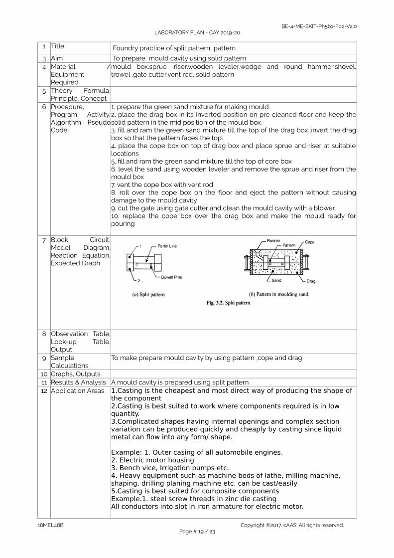
1 Title Foundry practice of split pattern pattern
3 Aim To prepare mould cavity using solid pattern 4 Material /
EquipmentRequired
mould box,sprue ,riser,wooden leveler,wedge and round hammer,shovel,trowel ,gate cutter,vent rod, solid pattern
5 Theory, Formula,Principle, Concept
6 Procedure,Program, Activity,Algorithm, PseudoCode
1. prepare the green sand mixture for making mould2. place the drag box in its inverted position on pre cleaned floor and keep thesolid pattern in the mid position of the mould box.3. fill and ram the green sand mixture till the top of the drag box .invert the dragbox so that the pattern faces the top.4. place the cope box on top of drag box and place sprue and riser at suitablelocations5. fill and ram the green sand mixture till the top of core box6. level the sand using wooden leveler and remove the sprue and riser from themould box7. vent the cope box with vent rod8. roll over the cope box on the floor and eject the pattern without causingdamage to the mould cavity9. cut the gate using gate cutter and clean the mould cavity with a blower.10. replace the cope box over the drag box and make the mould ready forpouring
7 Block, Circuit,Model Diagram,Reaction Equation,Expected Graph
8 Observation Table,Look-up Table,Output
9 SampleCalculations
To make prepare mould cavity by using pattern ,cope and drag
10 Graphs, Outputs11 Results & Analysis A mould cavity is prepared using split pattern 12 Application Areas 1.Casting is the cheapest and most direct way of producing the shape of
the component2.Casting is best suited to work where components required is in low quantity.3.Complicated shapes having internal openings and complex section variation can be produced quickly and cheaply by casting since liquid metal can flow into any form/ shape.
Example: 1. Outer casing of all automobile engines.2. Electric motor housing3. Bench vice, Irrigation pumps etc.4. Heavy equipment such as machine beds of lathe, milling machine, shaping, drilling planing machine etc. can be cast/easily 5.Casting is best suited for composite componentsExample.1. steel screw threads in zinc die casting All conductors into slot in iron armature for electric motor.
18MEL48B Copyright ©2017. cAAS. All rights reserved.Page # 19 / 23

BE-4-ME-SKIT-Ph5b1-F02-V2.0LABORATORY PLAN - CAY 2019-20
13 Remarks14 Faculty Signature
with Date
Experiment 08:FOUNDRY PRACTICE
- Experiment No.: 6 Marks DatePlanned
DateConducted
1 Title Foundry practice of solid pattern
3 Aim To prepare mould cavity of cube of sides 80mm with out using pattern4 Material /
EquipmentRequired
mould box,sprue ,riser,wooden leveler,wedge and round hammer,shovel,trowel ,gate cutter,vent rod, solid pattern
5 Theory, Formula,Principle, Concept
6 Procedure,Program, Activity,Algorithm, PseudoCode
1. prepare the green sand mixture for making mould2. place the drag box in its inverted position on pre cleaned floor and keep thesolid pattern in the mid position of the mould box.3. fill and ram the green sand mixture till the top of the drag box .invert the dragbox so that the pattern faces the top.4. place the cope box on top of drag box and place sprue and riser at suitablelocations5. fill and ram the green sand mixture till the top of core box6. level the sand using wooden leveler and remove the sprue and riser from themould box7. vent the cope box with vent rod8. roll over the cope box on the floor and eject the pattern without causingdamage to the mould cavity9. cut the gate using gate cutter and clean the mould cavity with a blower.10. replace the cope box over the drag box and make the mould ready forpouring
7 Block, Circuit,Model Diagram,Reaction Equation,Expected Graph
8 Observation Table,Look-up Table,Output
9 SampleCalculations
10 Graphs, Outputs
Experiment 09:FOUNDRY MODELS
- Experiment No.: 6 Marks DatePlanned
DateConducted
1 Title Preparation of forging models
3 Aim To prepare a 9x9 mm square bar from a 12mm dia cylinder bar4 Material mould box,sprue ,riser,wooden leveler,wedge and round hammer,shovel,
18MEL48B Copyright ©2017. cAAS. All rights reserved.Page # 20 / 23

BE-4-ME-SKIT-Ph5b1-F02-V2.0LABORATORY PLAN - CAY 2019-20
EquipmentRequired
trowel ,gate cutter,vent rod, solid pattern
5 Theory, Formula,Principle, Concept
A= 3.142/d2
6 Procedure,Program, Activity,Algorithm, PseudoCode
1. ignite the coal in open hearth type furnance and switch on the blower 2. keep the given square bar work piece in the hearth and heat to red hottemperature3. with the help of hammer ,anvil draw down the heated circular rod to thecalculated length4. finish the work piece using the flatter5. cool the finished model by keeping it in air or quenching in cold water
7 Block, Circuit,Model Diagram,Reaction Equation,Expected Graph
8 Observation Table,Look-up Table,Output
9 SampleCalculations
Calculations are done for different shape and find out area for given diameter
10 Graphs, Outputs11 Results & Analysis Prepared a given model to the required dimension 12 Application Areas Hexagonal nut and bolt , model preparation13 Remarks14 Faculty Signature
with Date
Experiment 10:FOUNDRY MODELS
- Experiment No.: 6 Marks DatePlanned
DateConducted
1 Title Preparation of forging models
3 Aim To forge a L shaped bar 9x9 mm square bar from a 12mm bar4 Material Equipment
Required mould box,sprue ,riser,wooden leveler,wedge and round hammer,shovel,trowel ,gate cutter,vent rod, solid pattern
5 Theory, Formula,Principle, Concept
A= 3.142/d2
6 Procedure, Program,Activity, Algorithm,Pseudo Code
1. Ignite the coal in open hearth type furnance and switch on the blower 2. keep the given square bar work piece in the hearth and heat to red hottemperature3. with the help of hammer ,anvil draw down the heated circular rod to thecalculated length4. finish the work piece using the flatter5. cool the finished model by keeping it in air or quenching in cold water
7 Block, Circuit, ModelDiagram, ReactionEquation, ExpectedGraph
Calculation of length of the raw material required to prepare the modelconsidering scale loss.
8 Observation Table,Look-up Table, Output
18MEL48B Copyright ©2017. cAAS. All rights reserved.Page # 21 / 23

BE-4-ME-SKIT-Ph5b1-F02-V2.0LABORATORY PLAN - CAY 2019-20
9 Sample Calculations Calculations are done for different shape and find out area10 Graphs, Outputs
Preparing minimum three forged models involving upsetting, drawing andbending operations
11 Results & Analysis Prepared a given model to the required dimension 12 Application Areas Hexagonal nut and bolt , model preparation13 Remarks14 Faculty Signature with
Date
F. Content to Experiment Outcomes1. TLPA Parameters
Table 1: TLPA –
Expt-#
Course Content or Syllabus(Split module content into 2 parts which
have similar concepts)
ContentTeaching Hours
Blooms’Learning
Levelsfor
Content
FinalBlooms’
Level
IdentifiedAction
Verbs forLearning
Instruction
Methodsfor
Learning
AssessmentMethods to
MeasureLearning
A B C D E F G H1 Testing of Molding sand and Core sand
Preparation of sand specimens and conduction of the following tests:
1. Compression, Shear and Tensile tests on Universal Sand Testing Machine.
2. Permeability test3. Sieve Analysis to find Grain
Fineness Number(GFN) of Base Sand
Clay content determination in Base Sand
3 L3(Apply)
L3(Appl
y)
Test Chalk &
Board,Demo
Practical record & IA
2 Foundry Practice1. Use of foundry tools and other
equipment’s.2. Preparation of molding sand
mixture.3. Preparation of green sand
molds using two molding boxes kept ready for pouring.· Using patterns (Single
piece pattern and Split pattern)
· Without patterns.· Incorporating core in the
mold. (Core boxes).· Preparation of one casting
(Aluminum or cast iron-Demonstration only)
3 L3(Apply)
L3(Appl
y)
Model Chalk &
Board,Demo
Practical record & IA
3 Forging Operations :Use of forging tools and other equipment’s
• Calculation of length of the raw material required to prepare the model considering scale losses.
• Preparing minimum three forged models involving upsetting, drawing and
bending operations.
3 L3(Apply)
L3(Appl
y)
Model Chalk &
Board,Demo
Practical record & IA
18MEL48B Copyright ©2017. cAAS. All rights reserved.Page # 22 / 23

BE-4-ME-SKIT-Ph5b1-F02-V2.0LABORATORY PLAN - CAY 2019-20
· Demonstration of forgingmodel using Power Hammer
4 WELDING PRACTICE L-Joint, T-joint, ButtJoint, V-Joint Lap Joint
3 L3(Apply)
L3(Appl
y)
Model Chalk &
Board,Demo
Practical record & IA
2. Concepts and Outcomes:Table 2: Concept to Outcome – Example Course
Expt- #
Learning orOutcome
from studyof the
Content orSyllabus
IdentifiedConcepts
fromContent
Final Concept ConceptJustification
(What all LearningHappened from thestudy of Content /Syllabus. A short
word for learning oroutcome)
CO Components(1.Action Verb,2.Knowledge,3.Condition /Methodology,4.Benchmark)
Course Outcome
Student Should beable to ...
A I J K L M N1 Testing of
Molding sand
Preparation of sand specimens
Clay contentdetermination in Base Sand
Will be able to understand the basic testing operations
Test Different TestingMethod
2 Molding Sand Mixture
Foundry Foundry Will be able to understand preparation of molding sand mixture
Model Preparation of molding sand mixture
3 Forging Operations
Forging Forging Will be able to understand preparation of forging models
Model Preparation of forging model
4 Welding ArcWelding
Arc Welding Will be able to understand arc welding operation
Model Welding models
18MEL48B Copyright ©2017. cAAS. All rights reserved.Page # 23 / 23