
SRF N-SERIES SURGE REDUCTION FILTERS · ERICO Surge Reduction Filters ... diversion stage to...
20
1 / 20 ENGINEERED ELECTRICAL AND FASTENING SOLUTIONS ERICO CRITEC SRF N-Series Installation Manual IP8344 ERICO Surge Reduction Filters (SRFs) from Pentair incorporate high energy clamping devices and special filtering circuitry. SRFs are installed in series with the circuit, usually at the point of entry to the building or structure. They are available in single or three-phase configurations for load currents from 63A to 800A per phase. The purpose of an SRF is to filter and protect against lightning induced transients. The SRF provides a clean, filtered supply of electricity to all output connected equipment when installed in accordance with the manufacturers’ instructions. Protection is achieved via a three stage circuit. This includes the internal ERICO Spark Gap unit as the primary surge diverter, a purpose designed low pass filter network and a secondary Transient Discriminating (TD) diversion stage to further clamp the transient energy to safe levels. This allows the SRF to: • Provide filtering to the clamped waveform in order to reduce the rate of voltage rise. • Provide a secondary stage of surge diversion to protect equipment from transients which may be induced onto the SRF output cables or be caused by the load itself. The use of this combination of technologies provides the benefits of high surge capability, low let through voltage and considerably reduced dv/dt. This applies to both surge performance and over-voltage withstand from short and long duration high-energy surges. SRF N-SERIES SURGE REDUCTION FILTERS INSTALLATION AND OPERATING INSTRUCTIONS 1 INTRODUCTION No CONTENTS 1 Intoduction ........................ Page 1 2 Warning..............................Page 2 3 Installation Cautions..........Page 2 4 Identify The Distribution System ...............................Page 3 5 Mounting The Srf ...............Page 6 6 Optimising Performance....Page 7 7 Servicing And Troubleshooting..................Page 14 8 Backplane Models .............Page 16 9 Schematic Diagrams..........Page 16 10 Physical Dimensions..........Page 17
Transcript of SRF N-SERIES SURGE REDUCTION FILTERS · ERICO Surge Reduction Filters ... diversion stage to...

1 / 20ENGINEERED ELECTRICAL AND FASTENING SOLUTIONS ERICO CRITEC SRF N-Series Installation Manual IP8344
ERICO Surge Reduction Filters (SRFs) from Pentair incorporate high energy clamping devices and special filtering circuitry. SRFs are installed in series with the circuit, usually at the point of entry to the building or structure. They are available in single or three-phase configurations for load currents from 63A to 800A per phase.
The purpose of an SRF is to filter and protect against lightning induced transients. The SRF provides a clean, filtered supply of electricity to all output connected equipment when installed in accordance with the manufacturers’ instructions.
Protection is achieved via a three stage circuit. This includes the internal ERICO Spark Gap unit as the primary surge diverter, a purpose designed low pass filter network and a secondary Transient Discriminating (TD) diversion stage to further clamp the transient energy to safe levels. This allows the SRF to: • Provide filtering to the clamped waveform in order to reduce the rate of voltage rise.• Provide a secondary stage of surge diversion to protect equipment from transients
which may be induced onto the SRF output cables or be caused by the load itself.
The use of this combination of technologies provides the benefits of high surge capability, low let through voltage and considerably reduced dv/dt. This applies to both surge performance and over-voltage withstand from short and long duration high-energy surges.
SRF N-SERIES SURGE REDUCTION FILTERS
INSTALLATION AND OPERATING INSTRUCTIONS
1 INTRODUCTIONNo CONTENTS
1 Intoduction ........................ Page 1
2 Warning..............................Page 23 Installation Cautions..........Page 2
4 Identify The Distribution System ...............................Page 3
5 Mounting The Srf ...............Page 66 Optimising Performance....Page 7
7 Servicing And Troubleshooting..................Page 14
8 Backplane Models .............Page 169 Schematic Diagrams..........Page 16
10 Physical Dimensions..........Page 17

INSTALLATION & OPERATING INSTRUCTIONS
2 / 20 ENGINEERED ELECTRICAL AND FASTENING SOLUTIONS IP8344 ERICO CRITEC SRF N-Series Installation Manual
3 INSTALLATION CAUTIONS
• Transient protection devices are usually rated to protect against non-repetitive pulses from sources such as direct or induced lightning energy.
• They are not designed to provide protection against repeated cyclic anomalies such as those caused by motor speed control notching (variable speed controls, etc).
• SRFs are not designed to provide protection against sustained over-voltage conditions where the supply voltage exceeds, for an extended period of time, the nominal rating of the protection equipment. i.e continuous over-voltages from poorly regulated generators or distribution systems.
• Smaller power generation equipment does not always conform to the same standards of voltage regulation that is in place for mains power reticulation. A large number of smaller or cheaper generators have a voltage waveform that approximates 240Vrms (often poorly regulated), but more importantly, which often contains significant higher order harmonics and may exhibit a peak voltage on each half cycle far in excess of the normal 340V (peak). Such machines are usually capacitive excitation induction generators, as opposed to synchronous generators. The problem is usually increased when the generator is lightly loaded.
• Harmonic voltages may also be present in distribution systems that do not feature generators. This is normally where non-linear loads are used, such as UPSs, rectifiers, switch-mode power supplies and motor speed controls.
The harmonic voltages may have peak voltages in excess of the protective clamping voltages, causing problems such as excessive heat build up. Because the harmonic waveforms contain higher order frequencies, capacitive leakage currents may increase to above prescribed limits and shorten the life of the SRF. It should be noted that in sites with large harmonic voltage distortion, the SRF capacitance may dramatically affect the power factor.
• Seek the manufacturers’ advice before installing any SRF into a circuit which features a total harmonic voltage ratio above 5%.
• With large transients, significant energy may be passed by the SRF diverters back to the source or to earth. This may, under some circumstances, cause upstream earth leakage circuit breakers or residual current devices (ELCBs & RCDs) to nuisance trip. Where possible, these devices should be installed after the SRF in order to reduce this possibility.
• Transient protection devices often have minimum requirements for upstream fusing to ensure proper operation. See section 6.1 for fusing requirements.
• By-pass switches are not recommended to be used with SRFs as they compromise the protection offered. The connection of the by-pass switch compromises the input to output separation requirement by bringing the SRF input and output wiring into close proximity at the switch.
SRF
SRF
SRFSRF SRF
ELCB or
RCD
NON PREFERRED NON PREFERRED PREFERRED
AVOID UPSTREAM EARTH LEAKAGE CIRCUIT BREAKERS (ELCB’S) OR RESIDUAL CURRENT DEVICES (RCD’S)
BYPASS SWITCHES
BYPASS SWITCHES COMPROMISE PROTECTION
AVOID REPETITIVE VOLTAGES IN EXCESS OF SRF RATING AVOID HIGH HARMONIC VOLTAGES
276 Vrms Or
276 Vrms
276 Vrms 240 Vrms
240 Vrms
GENERATOR
GENERATOR
GENERATOR GENERATOR
SRF SRF
MAINS / GENERATOR CHANGE OVER SWITCH CONNECTION
Figure 1. Seek specialist advice with the above installations.
HAZARDOUS VOLTAGES EXIST WITHIN THE SRF ENCLOSURE. THIS UNIT SHOULD BE INSTALLED & SERVICED ONLY BY QUALIFIED PERSONNEL AND IN ACCORDANCE WITH RELEVANT NATIONAL ELECTRICAL & SAFETY CODES. ALL INSTRUCTIONS MUST BE FOLLOWED TO ENSURE CORRECT AND SAFE OPERATION OF THE SRF. • Over-current and short-circuit protection must be provided
to protect the SRF and associated wiring if a fault develops. The over-current protection should be installed in such a manner as to provide a means of isolating the SRF from the main supply. This unit contains overvoltage protection components and may be damaged by installation resistance testing.
• SRFs contain capacitors. Disconnect power at least 1 minute prior to opening door. Check voltage prior to working on SRF internals.
• SRFs must be connected to a low impedance earth (<10Ω) for correct operation.
• SRFs must be installed in accordance with ALL relevant national electrical and safety codes.
• The power supply to the SRF should always be turned off (and locked) before the door is opened for any purpose.
• Check all SRF terminals for tight connections. (Some terminals may become loose during transport).
• Ensure all input and output cabling, once installed is tightened to the correct torque settings (see table 2).
• Do not disconnect upstream Earth or Neutral connections supplying the SRF while power is still applied, as this may damage the SRF or load.
• No combustible items should be stored within the SRF during operation.
• Do not leave this manual inside the SRF after applying power to the SRF. Retain this manual for future reference.
• Failure to heed instructions or warnings may result in personnel injury, equipment damage or ineffective transient protection.
2 WARNING
3 / 20ENGINEERED ELECTRICAL AND FASTENING SOLUTIONS
INSTALLATION & OPERATING INSTRUCTIONS
ERICO CRITEC SRF N-Series Installation Manual IP8344
4 IDENTIFY THE DISTRIBUTION SYSTEM
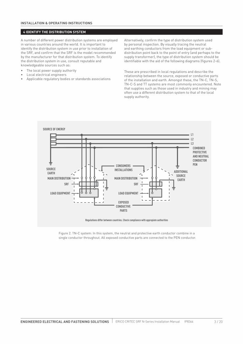
A number of different power distribution systems are employed in various countries around the world. It is important to identify the distribution system in use prior to installation of the SRF, and confirm that the SRF is the model recommended by the manufacturer for that distribution system. To identify the distribution system in use, consult reputable and knowledgeable sources such as:• The local power supply authority• Local electrical engineers• Applicable regulatory bodies or standards associations
Alternatively, confirm the type of distribution system used by personal inspection. By visually tracing the neutral and earthing conductors from the load equipment or sub-distribution point back to the point of entry (and perhaps to the supply transformer), the type of distribution system should be identifiable with the aid of the following diagrams (figures 2-6).
These are prescribed in local regulations and describe the relationship between the source, exposed or conductive parts of the installation and earth. Amongst these, the TN-C, TN-S, TN-C-S and TT systems are most commonly encountered. Note that supplies such as those used in industry and mining may often use a different distribution system to that of the local supply authority.
Regulations differ between countries. Check compliance with appropiate authorities
Figure 2. TN-C system: In this system, the neutral and protective earth conductor combine in a single conductor throughout. All exposed conductive parts are connected to the PEN conductor.

INSTALLATION & OPERATING INSTRUCTIONS
4 / 20 ENGINEERED ELECTRICAL AND FASTENING SOLUTIONS IP8344 ERICO CRITEC SRF N-Series Installation Manual
SOURCE OF ENERGY
Figure 3. TN-S system: In this system, a separate neutral and protective earth conductor are run throughout. The protective PE conductor can be the metalic sheath of the power distribution cable or separate conductor. All exposed conductive parts of the installation are conducted to this PE conductor.
Figure 4. TN-C-S system: In this system, a separate neutral and protective earth functions combine in a single PEN conductor. This system is also known as a Multiple Earthed (MEN) system and the protective conductor is referred to as the combined neutral earth (CNE) conductor The supply PEN conductor is earthed at a number of points throughout the network and generally as close to the consumer's point of entry as possible. All exposed conductive parts are connected to the CNE conductor.
4 IDENTIFY THE DISTRIBUTION SYSTEM
5 / 20ENGINEERED ELECTRICAL AND FASTENING SOLUTIONS
INSTALLATION & OPERATING INSTRUCTIONS
ERICO CRITEC SRF N-Series Installation Manual IP8344
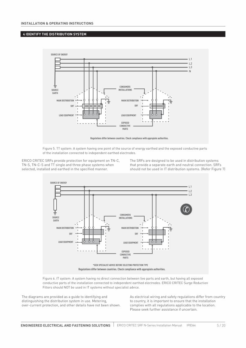
ERICO CRITEC SRFs provide protection for equipment on TN-C, TN-S, TN-C-S and TT single and three phase systems when selected, installed and earthed in the specified manner.
The diagrams are provided as a guide to identifying and distinguishing the distribution system in use. Metering, over-current protection, and other details have not been shown.
The SRFs are designed to be used in distribution systems that provide a separate earth and neutral connection. SRFs should not be used in IT distribution systems. (Refer Figure 7)
As electrical wiring and safety regulations differ from country to country, it is important to ensure that the installation complies with all regulations applicable to the location. Please seek further assistance if uncertain.
L3N
L2L1
SOURCE OF ENERGY
SOURCE EARTH
LOAD EQUIPMENTLOAD EQUIPMENT
CONSUMERS INSTALLATIONS
Regulations differ between countries. Check compliance with appropiate authorities.
EXPOSEDCONDUCTIVE
PARTS
SRFSRF
MAIN DISTRIBUTIONMAIN DISTRIBUTION
Regulations differ between countries. Check compliance with appropiate authorities.
Figure 5. TT system: A system having one point of the source of energy earthed and the exposed conductive parts of the installation connected to independent earthed electrodes.
Figure 6. IT system: A system having no direct connection between live parts and earth, but having all exposed conductive parts of the installation connected to independent earthed electrodes. ERICO CRITEC Surge Reduction Filters should NOT be used in IT systems without specialist advice.
4 IDENTIFY THE DISTRIBUTION SYSTEM

INSTALLATION & OPERATING INSTRUCTIONS
6 / 20 ENGINEERED ELECTRICAL AND FASTENING SOLUTIONS IP8344 ERICO CRITEC SRF N-Series Installation Manual
5 MOUNTING THE SRF
Before mounting the SRF, refer to Table 3 (weights and dimensions on last page of this manual) which provides dimensions and unit weights. Ensure that appropriate lifting equipment is used when installing the larger SRFs. When installing the SRF, consideration should be given to future service needs. Ensure that clear view of the status indicators is provided. The SRFs should be mounted away from other electrical apparatus (300mm minimum) and in a position that avoids close proximity to combustible materials.
The SRFs are designed to be wall mounted. Mounting brackets (as shown in Figure 7) are supplied. The internal backplane may be removed to facilitate wall mounting. Carefully disconnect the wiring going to the front door LED before removing backplane.
The cabling and upstream over-current protection requirements and all instructions provided in this manual, should be taken into consideration before mounting the SRF.
To preserve the IP rating, SRF units from 63A to 250 A must be installed in accordance with figure 9 and section 6.2.• Larger SRF units from 500A to 800A are ventilated and
should be mounted in a dust and moisture-free, ventilated environment.
• All SRFs should be installed in a dry, well-ventilated area. Avoid sites subject to moisture ingress.
• SRFs are not intended for use in harsh or corrosive environments.
Where the SRF is to be enclosed in a switch board cubicle, models are available without the enclosure. These backplane units are denoted by the model number suffix ‘BP’.
SUITABLE WALL ANCHORING
SEE TABLE 3 FOR MOUNTING DIMENSIONS
WASHER
INTERNAL NUTS
BRACKET
BRACKET. INSTALLER TO PROVIDE SUITABLE ANCHOR BOLT
Figure 7a. Typical mounting arrangement for wall mounted ERICO CRITEC Surge Reduction Filters (63A to 250A).
Figure 7b: Typical mounting arrangement (500A to 800A).

7 / 20ENGINEERED ELECTRICAL AND FASTENING SOLUTIONS
INSTALLATION & OPERATING INSTRUCTIONS
ERICO CRITEC SRF N-Series Installation Manual IP8344
6 OPTIMISING PERFORMANCE
6.1 FUSING
6.2 Cabling
The protection equipment must be earthed and installed in accordance with all relevant national electrical and safety standards. The term "point of entry” protection, is a general descriptive concept of zonal boundary protection, as detailed in standards such as IEC 62305. Some local wiring regulations may allow the protection equipment to be mounted directly at the point of entry, while other countries require protection equipment to be installed after the metering or main circuit isolators or over-current protection.
The following installation points require attention to ensure that optimal protection is provided by the protection equipment. This information is provided as a guide only. Compliance with local electrical and safety regulations must be ensured.
Over-current and short-circuit protection must be provided in order to protect the SRF and associated wiring if a fault develops. The over-current protection should be installed in such a manner as to provide a means of isolating the SRF from the mains supply. This is an important safety consideration.
The SRF N-Series SRFs do not incorporate overcurrent protection. Upstream fusing or circuit breakers MUST be
installed. The amperage of this upstream overcurrent protection must not exceed the load current rating of the SRF. For example, the SRF25ON filter should be installed with upstream protection rated at less than or equal to 250A. The load current rating of the filter is noted on the Ratings Label on the inside of the SRF enclosure door (and duplicated on the external side surface of the enclosure).
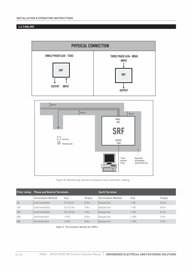
The cabling and earth wires connected to the filter input should always be run separately, with a minimum clearance of 300mm between them and all other cables or sensitive equipment (as shown in Figure 8 ). The input cable and earth wire will carry the transient energy, while the protected output cable can be considered to be a “clean filtered” supply.
By separating these cables, any incoming transients will not be induced from the input cables onto nearby clean cables. This clearance will reduce the possibility of arc-over from input to output cables. Where cables need to run closer together due to space restrictions, input and output cables should cross at right angles and not be installed parallel to each other. Cabling should be sized in accordance with all relevant wiring standards to ensure that the full load current can be safely supplied. All cabling or busbars connected to the protection equipment should be securely anchored to prevent undue stress being applied to input/output terminals.
Input and output terminal requirements are detailed in Table 2.
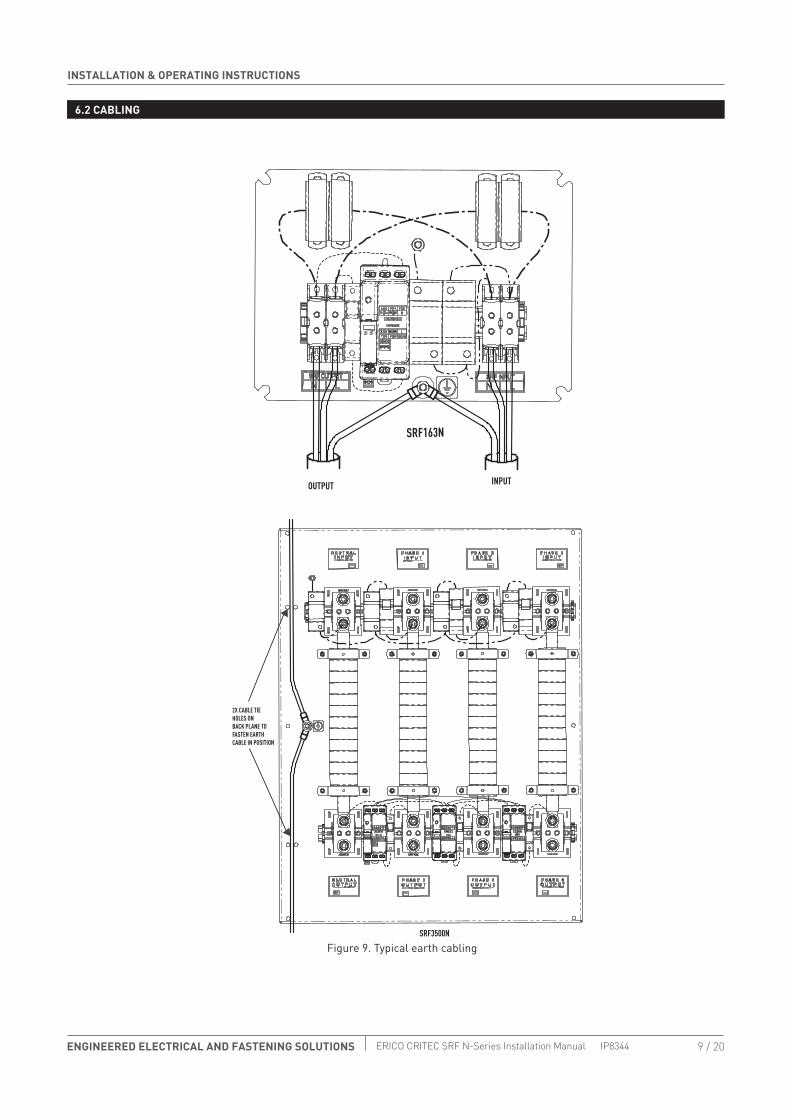
The input and output earth connections connect together on the backplane earthing stud. This earthing stud provides the function of connecting these earths together for continuity, and also the functional electrical earthing of the SRF, together with the safety earthing of the SRF enclosure. The 250A to 800A SRFs have cable tie holes in the backplane to allow the incoming and outgoing earth cables to be secured to the backplane (see Figure 9).
• Cable glands (of an appropriate design) must be used for all input and output cables to preserve the IP rating of the 63A to 250A SRFs.
• To protect input and output cabling insulation from sharp edges around the cable entry holes suitable cable glands or grommets must be installed.
INSTALLATION & OPERATING INSTRUCTIONS
8 / 20 ENGINEERED ELECTRICAL AND FASTENING SOLUTIONS IP8344 ERICO CRITEC SRF N-Series Installation Manual
Filter rating Phase and Neutral Terminals Earth Terminal
Termination Method Size Torque Termination Method Size Torque
63A Screw Terminal Block 10 to 35 mm2 8.5 N.m Backplane Stud 1 x M8 8.5 N.m
125A Screw Terminal Block 25 to 120 mm2 19 N.m Backplane Stud 1 x M8 8.5 N.m
250A Screw Terminal Block 25 to 120 mm2 19 N.m Backplane Stud 1 x M8 8.5 N.m
500A Stud Terminal Block 1 x M10 30 N.m Backplane Stud 1 x M10 17 N.m
800A Stud Terminal Block 2 x M10 30 N.m Backplane Stud 1 x M10 17 N.m
SINGLE PHASE (63A - 125A)
SRF
300 mm
300 mm 300 mm
INPUT LINE
OUTPUT LOAD
“Clean” protected wiring
Keep cables and equipment away from this area
Safe area
Hazardous area
Figure 8. Maintaining clearance between input and other cabling.
Table 2. Termination details for SRFs
6.2 CABLING
9 / 20ENGINEERED ELECTRICAL AND FASTENING SOLUTIONS
INSTALLATION & OPERATING INSTRUCTIONS
ERICO CRITEC SRF N-Series Installation Manual IP8344
SRF163N
SRF3500N
2X CABLE TIE HOLES ONBACK PLANE TO FASTEN EARTH CABLE IN POSITION
OUTPUT INPUT
6.2 CABLING
Figure 9. Typical earth cabling
INSTALLATION & OPERATING INSTRUCTIONS
10 / 20 ENGINEERED ELECTRICAL AND FASTENING SOLUTIONS IP8344 ERICO CRITEC SRF N-Series Installation Manual
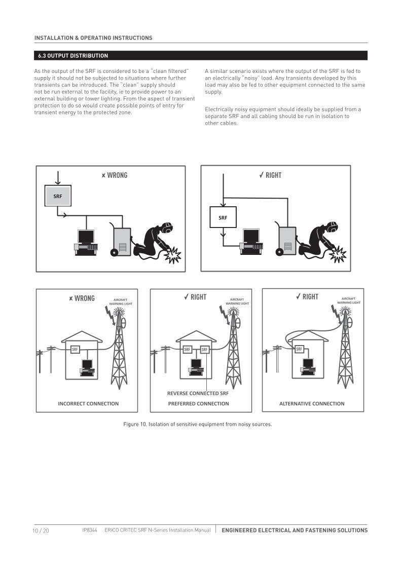
6.3 OUTPUT DISTRIBUTION
As the output of the SRF is considered to be a “clean filtered” supply it should not be subjected to situations where further transients can be introduced. The “clean” supply should not be run external to the facility, ie to provide power to an external building or tower lighting. From the aspect of transient protection to do so would create possible points of entry for transient energy to the protected zone.
A similar scenario exists where the output of the SRF is fed to an electrically “noisy” load. Any transients developed by this load may also be fed to other equipment connected to the same supply.
Electrically noisy equipment should ideally be supplied from a separate SRF and all cabling should be run in isolation to other cables.
SRF
RIGHT
RIGHT
SRF
ALTERNATIVE CONNECTION
AIRCRAFT WARNING LIGHT
AIRCRAFT WARNING LIGHT
AIRCRAFT WARNING LIGHT
PREFERRED CONNECTION
REVERSE CONNECTED SRF
INCORRECT CONNECTION
WRONG
WRONG
SRF
SRF SRF
RIGHT
SRF
Figure 10. Isolation of sensitive equipment from noisy sources.

11 / 20ENGINEERED ELECTRICAL AND FASTENING SOLUTIONS
INSTALLATION & OPERATING INSTRUCTIONS
ERICO CRITEC SRF N-Series Installation Manual IP8344
6.4 EARTHING
The earths for all site equipment should be integrated (preferably deploying a single point earthing approach) and an equipotential earth plane should be created. Integral to this is the elimination of earth loops. It is common, but incorrect from the point of lightning protection for there to be separate earths for various services, ie electricity mains, telephone. computer equipment and other building services.
For sites where the interconnection of these earths is difficult, either for practical or regulatory reasons, the use of a Potential Equalisation Clamp (PEC) is recommended. The PEC behaves as an open circuit under normal operation, but under surge conditions it activates to effectively clamp individual points together.
The effectiveness of an SRF is intimately related to the impedance presented by the earthing system to which it is
connected. A low impedance route to the earth is required (less than 10 Ω). This can be achieved by ensuring that the earth electrode system at the site presents a low surge impedance with respect to the ground. Additionally, the interconnecting cabling must be of adequate cross sectional area and be routed to provide as short and direct a path as is practical.
The earth conductor for the SRF should be sized according to local regulations but with a minimum size of 6mm2, Every attempt should be made to limit the cable length to under 5 metres. By selecting the most direct route, with the minimum possible number of bends to the earth point or internal earth bar, the risk of side flashing and excessive voltage rise across the equipment is reduced. Figure 14 depicts the correct earthing concept as described above.
ALL POWER AND DATA CABLES ENTER OR LEAVE THE BUILDING ON THE SAME SIDE (TO AVOID EARTH LOOPS)
Figure 11. Preferred approach to equipotential bonding.

INSTALLATION & OPERATING INSTRUCTIONS
12 / 20 ENGINEERED ELECTRICAL AND FASTENING SOLUTIONS IP8344 ERICO CRITEC SRF N-Series Installation Manual
6.5 CONNECTION OF ALARM CIRCUITS
6.6 INSTALLATION ARRANGEMENT FOR AUSTRALIAN MEN SYSTEMS
The SRF secondary surge diverters are continuously monitored and their internal protection status is identified by the green LED on each phase blue secondary Unit (SRFSUAC for phase 1, and SRFSU on phases 2 and 3 if present).
Reduction in surge handling capacity activates a set of voltage free alarm contacts which can be used to shut down the load or to activate an external warning.
When mains voltage is applied to the SRF and the surge diverters are fully functional, the alarm contacts will be in the energized or normal state. The NC contact will be in short circuit with the COM contact. Should the surge handling capacity fall to below the alarm threshold, these contacts will be in the de-energised or alarm state and the NO contact will be in short circuit with the COM contact.
The contacts are “Fail-Safe’ in that, if power to the unit fails, the contacts will revert to the de-energised or alarm state.
The alarm contacts should only be connected by an appropriately qualified person owing to the possibility of mains voltage being present in the SRF cabinet. Care should be taken to route the alarm wiring away from the input circuit and any other current-carrying conductors.
Alarm contact ratings: • 5A @ 250VAC• 54 @ 30 VDC• 4kV Isolation
See section 7 “Servicing and Trouble Shooting” for further information.
Under Australian Standards classification, SRFs are considered a piece of equipment to be connected to the mains supply. They are not intended for use as switchboards, distribution boards or other equipment. As these devices are classified as “electrical equipment AS 3000 Wiring Regulations apply to the installation and operation of the units.AS 3000 specifies minimum requirements for electrical equipment that is connected to switch boards or distribution boards. For a point of entry application in the multiple earth neutral (MEN) distribution system, the SRF equipment should be installed as close as possible after the MEN point and after
both the main disconnect switch/over-current protector and any metering equipment. The SRF therefore, may not be installed at the physical “point of entry” of the mains power to the building. It must be earthed and installed in accordance with all other applicable electrical and safety standards. As the protection equipment is hardwired, the installation must be inspected by an appropriately authorized electrical authority official prior to commissioning.
Figure 12. Typical connection detail for SRF point of entry installation in MEN system.
13 / 20ENGINEERED ELECTRICAL AND FASTENING SOLUTIONS
INSTALLATION & OPERATING INSTRUCTIONS
ERICO CRITEC SRF N-Series Installation Manual IP8344
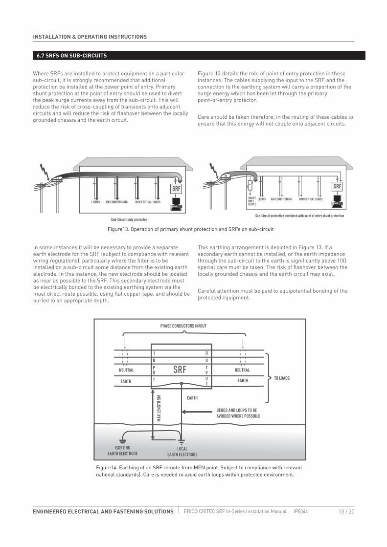
6.7 SRFS ON SUB-CIRCUITS
Where SRFs are installed to protect equipment on a particular sub-circuit, it is strongly recommended that additional protection be installed at the power point of entry. Primary shunt protection at the point of entry should be used to divert the peak surge currents away from the sub-circuit. This will reduce the risk of cross-coupling of transients onto adjacent circuits and will reduce the risk of flashover between the locally grounded chassis and the earth circuit.
Figure 13 details the role of point of entry protection in these instances. The cables supplying the input to the SRF and the connection to the earthing system will carry a proportion of the surge energy which has been let through the primary point-of-entry protector.
Care should be taken therefore, in the routing of these cables to ensure that this energy will not couple onto adjacent circuits.
In some instances it will be necessary to provide a separate earth electrode for the SRF (subject to compliance with relevant wiring regulations), particularly where the filter is to be installed on a sub-circuit some distance from the existing earth electrode. In this instance, the new electrode should be located as near as possible to the SRF. This secondary electrode must be electrically bonded to the existing earthing system via the most direct route possible, using flat copper tape, and should be buried to an appropriate depth.
This earthing arrangement is depicted in Figure 13. If a secondary earth cannot be installed, or the earth impedance through the sub-circuit to the earth is significantly above 10Ω special care must be taken. The risk of flashover between the locally grounded chassis and the earth circuit may exist.
Careful attention must be paid to equipotential bonding of the protected equipment.
Figure14. Earthing of an SRF remote from MEN point. Subject to compliance with relevant national standards). Care is needed ro avoid earth loops within protected environment.
Figure13. Operation of primary shunt protection and SRFs on sub-circuit
INSTALLATION & OPERATING INSTRUCTIONS
14 / 20 ENGINEERED ELECTRICAL AND FASTENING SOLUTIONS IP8344 ERICO CRITEC SRF N-Series Installation Manual
7 SERVICING AND TROUBLESHOOTING
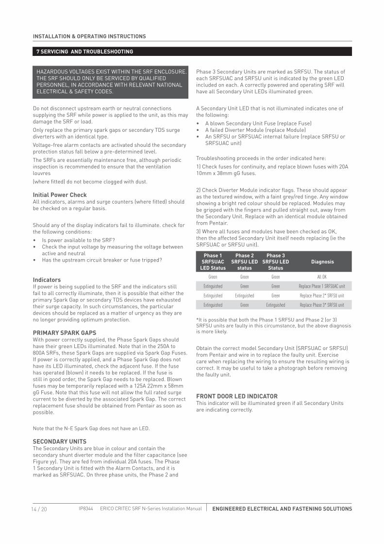
HAZARDOUS VOLTAGES EXIST WITHIN THE SRF ENCLOSURE. THE SRF SHOULD ONLY BE SERVICED BY QUALIFIED PERSONNEL, IN ACCORDANCE WITH RELEVANT NATIONAL ELECTRICAL & SAFETY CODES.
Do not disconnect upstream earth or neutral connections supplying the SRF while power is applied to the unit, as this may damage the SRF or load.Only replace the primary spark gaps or secondary TDS surge diverters with an identical type.Voltage-free alarm contacts are activated should the secondary protection status fall below a pre-determined level.The SRFs are essentially maintenance free, although periodic inspection is recommended to ensure that the ventilation louvres(where fitted) do not become clogged with dust.
Initial Power Check All indicators, alarms and surge counters (where fitted) should be checked on a regular basis.
Should any of the display indicators fail to illuminate. check for the following conditions:• Is power available to the SRF?• Check the input voltage by measuring the voltage between
active and neutral• Has the upstream circuit breaker or fuse tripped?
Indicators If power is being supplied to the SRF and the indicators still fail to all correctly illuminate, then it is possible that either the primary Spark Gap or secondary TDS devices have exhausted their surge capacity. In such circumstances, the particular devices should be replaced as a matter of urgency as they are no longer providing optimum protection.
PRIMARY SPARK GAPSWith power correctly supplied, the Phase Spark Gaps should have their green LEDs illuminated. Note that in the 250A to 800A SRFs, these Spark Gaps are supplied via Spark Gap Fuses. If power is correctly applied, and a Phase Spark Gap does not have its LED illuminated, check the adjacent fuse. If the fuse has operated (blown) it needs to be replaced. If the fuse is still in good order, the Spark Gap needs to be replaced. Blown fuses may be temporarily replaced with a 125A 22mm x 58mm gG Fuse. Note that this fuse will not allow the full rated surge current to be diverted by the associated Spark Gap. The correct replacement fuse should be obtained from Pentair as soon as possible.
Note that the N-E Spark Gap does not have an LED.
SECONDARY UNITSThe Secondary Units are blue in colour and contain the secondary shunt diverter module and the filter capacitance (see Figure yy). They are fed from individual 20A fuses. The Phase 1 Secondary Unit is fitted with the Alarm Contacts, and it is marked as SRFSUAC. On three phase units, the Phase 2 and
Phase 3 Secondary Units are marked as SRFSU. The status of each SRFSUAC and SRFSU unit is indicated by the green LED included on each. A correctly powered and operating SRF will have all Secondary Unit LEDs illuminated green.
A Secondary Unit LED that is not illuminated indicates one of the following:• A blown Secondary Unit Fuse (replace Fuse)• A failed Diverter Module (replace Module)• An SRFSU or SRFSUAC internal failure (replace SRFSU or
SRFSUAC unit)
Troubleshooting proceeds in the order indicated here:1) Check fuses for continuity, and replace blown fuses with 20A 10mm x 38mm gG fuses.
2) Check Diverter Module indicator flags. These should appear as the textured window, with a faint grey/red tinge. Any window showing a bright red colour should be replaced. Modules may be gripped with the fingers and pulled straight out, away from the Secondary Unit. Replace with an identical module obtained from Pentair.3) Where all fuses and modules have been checked as OK, then the affected Secondary Unit itself needs replacing (ie the SRFSUAC or SRFSU unit).
*It is possible that both the Phase 1 SRFSU and Phase 2 (or 3) SRFSU units are faulty in this circumstance, but the above diagnosis is more likely.
Obtain the correct model Secondary Unit (SRFSUAC or SRFSU) from Pentair and wire in to replace the faulty unit. Exercise care when replacing the wiring to ensure the resulting wiring is correct. It may be useful to take a photograph before removing the faulty unit.
FRONT DOOR LED INDICATORThis indicator will be illuminated green if all Secondary Units are indicating correctly.
Phase 1 SRFSUAC
LED Status
Phase 2 SRFSU LED
status
Phase 3 SRFSU LED
Status Diagnosis
Green Green Green All OK
Extinguished Green Green Replace Phase 1 SRFSUAC unit
Extinguished Extinguished Green Replace Phase 2* SRFSU unit
Extinguished Green Extinguished Replace Phase 3* SRFSU unit

15 / 20ENGINEERED ELECTRICAL AND FASTENING SOLUTIONS
INSTALLATION & OPERATING INSTRUCTIONS
ERICO CRITEC SRF N-Series Installation Manual IP8344
7 SERVICING AND TROUBLESHOOTING
N-E SPARK GAP
PHASE SPARK GAPS
PHASE 2 SRFSU UNIT
PHASE 3 SRFSU UNIT
SPARK GAP FUSES (250A TO 800A MODELS)
PHASE 1 SRFSUAC UNIT
PHASE 1 SRFSUAC UNIT
SRF3500N
SECONDARY UNIT FUSES
N-E SPARK GAP
PHASE 1 SPARK GAPSECONDARY UNIT FUSE
SRF163N
GREEN STATUS INDICATING LED
DIVERTER MODULE STATUS INDICATING FLAG
ALARM CONTACTS (ON SRFSUAC ONLY )
FIGURE YY- SECONDARY UNITS ( SRFSUAC AND SRFSU)
Figure15. Part Identification
figure16. Secondary units (SRFSUAC and SRFSU)

INSTALLATION & OPERATING INSTRUCTIONS
16 / 20 ENGINEERED ELECTRICAL AND FASTENING SOLUTIONS IP8344 ERICO CRITEC SRF N-Series Installation Manual
8 BACKPLANE MODELS
9 SCHEMATIC DIAGRAMS
This document details the installation procedure for our current range of standard SRFs.Backplane units are also available, and are denoted by ‘BP’ as a suffix to the model number. These units are supplied without
the proprietary enclosure and are intended to be mounted in a customer's provided switchboard.
SINGLE-PHASE SRF MODELS
FUSESECONDARY UNIT
SG PRIMARY DIVERTER
SG DIVERTER
TD SECONDARY DIVERTER
INPUT/LINE OUTPUT/LOAD
A
N
AL
C
LN
E E
Figure 17 schematic diagram for single phase filter
Figure18. schematic diagram for three phase filter
17 / 20ENGINEERED ELECTRICAL AND FASTENING SOLUTIONS
INSTALLATION & OPERATING INSTRUCTIONS
ERICO CRITEC SRF N-Series Installation Manual IP8344
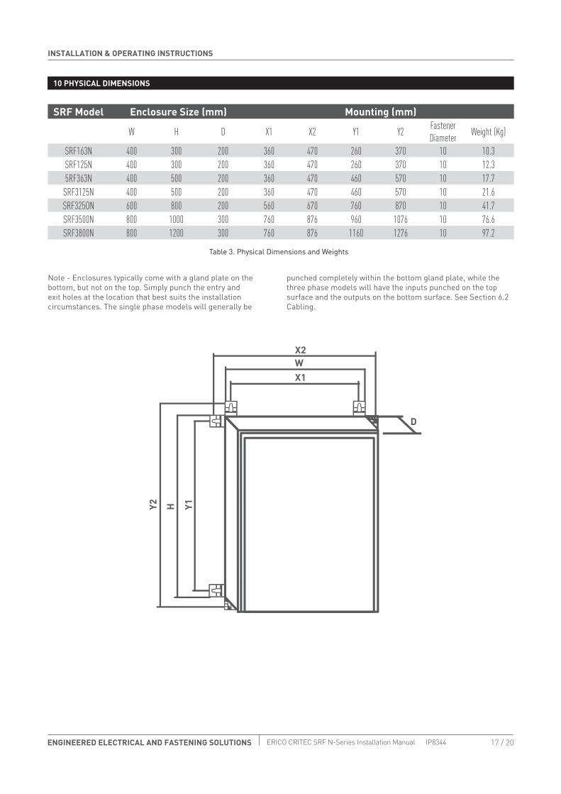
10 PHYSICAL DIMENSIONS
Note - Enclosures typically come with a gland plate on the bottom, but not on the top. Simply punch the entry and exit holes at the location that best suits the installation circumstances. The single phase models will generally be
punched completely within the bottom gland plate, while the three phase models will have the inputs punched on the top surface and the outputs on the bottom surface. See Section 6.2 Cabling.
SRF Model Enclosure Size (mm) Mounting (mm)
W H D X1 X2 Y1 Y2 Fastener Diameter Weight (Kg)
SRF163N 400 300 200 360 470 260 370 10 10.3SRF125N 400 300 200 360 470 260 370 10 12.35RF363N 400 500 200 360 470 460 570 10 17.7SRF3125N 400 500 200 360 470 460 570 10 21.6SRF325ON 600 800 200 560 670 760 870 10 41.7SRF3500N 800 1000 300 760 876 960 1076 10 76.6SRF3800N 800 1200 300 760 876 1160 1276 10 97.2
D
HY2 Y1
WX1
X2
Table 3. Physical Dimensions and Weights

INSTALLATION & OPERATING INSTRUCTIONS
18 / 20 ENGINEERED ELECTRICAL AND FASTENING SOLUTIONS IP8344 ERICO CRITEC SRF N-Series Installation Manual
4Power Protection TVSS DeviceCommunications Line Protection DeviceGround Electrode
Power Distribution Panel
Telephone Main Distribution Frame
PCS, Radio & Telemetry Equipment
Power Ground
AC Transformer Sub Station
Overhead Distribution Voltage Transmission Lines
Telephone Lines
Direct Lightning Strike
ERICO SYSTEM 3000 Active Lightning Protection System
1 Capture the lightning strike
3 Dissipate Energy into the Grounding System
Low Impedance Ground using flat copper radials and
Ground Enhancement Material
Inspection Well
2 Safely Convey Energy to Ground
5 Protect Incoming AC Power Feeders
IS File
Server
PABX
Inverter
Rectifier
Batteries
Ground Potential Equalization Bonding
TVSS
Remote Data Terminal
Sub-Distribution Board
Bond All Ground Points Together
PrinterBilling Computer
Signal Control Lines
Induced Surge
Because lightning protection, grounding, equipotential bonding and surge protection are all interdependent technologies, reliable protection of structures and operations demands an integrated system approach. ERICO SYSTEM 3000
Active Lightning Protection System
ERICO SYSTEM 2000 Conventional Lightning Protection System
6 Protect Low Voltage Data/Telecommunications Circuits
The Six Point Plan of Protection from ERICO
1
4
2
5
3
6
Capture the Lightning Strike
Protect Low Voltage Data Telecommunications Circuits
Safely Convey Energy to Ground
Protect Incoming AC Power Feeders
Bond All Ground Points Together
Dissipate Energy into the Grounding System

19 / 20ENGINEERED ELECTRICAL AND FASTENING SOLUTIONS
INSTALLATION & OPERATING INSTRUCTIONS
ERICO CRITEC SRF N-Series Installation Manual IP8344

Pentair is owned by Pentair or its global affiliates. All other trademarks are the property of their respective owners. Pentair reserves the right to change specifications without prior notice.
© 2016 Pentair.
WWW.ERICO.PENTAIR.COM
IP8344 Rev BENGINEERED ELECTRICAL AND FASTENING SOLUTIONS ERICO CRITEC SRF N-Series Installation Manual