SREE VAHINI INSTITUTE OF SCIENCE AND TECHNOLOGYSREE VAHINI INSTITUTE OF SCIENCE AND TECHNOLOGY a)...
38
SREE VAHINI INSTITUTE OF SCIENCE AND TECHNOLOGY
Transcript of SREE VAHINI INSTITUTE OF SCIENCE AND TECHNOLOGYSREE VAHINI INSTITUTE OF SCIENCE AND TECHNOLOGY a)...
SREE VAHINI INSTITUTE OF SCIENCE AND TECHNOLOGY
SREE VAHINI INSTITUTE OF SCIENCE AND TECHNOLOGY
EXPERIMENT NO: 1 DATE:
STUDY OF THEODOLITE AIM To study about the Temporary and Permanent adjustments of a Theodolite ADJUSTMENTS OF THEODOLITE The Theodolite should be properly adjusted to obtain accurate observations. The adjustments are mainly of two types. They are as follows:
1. Permanent adjustments and 2. Temporary adjustments
1. Permanent adjustments
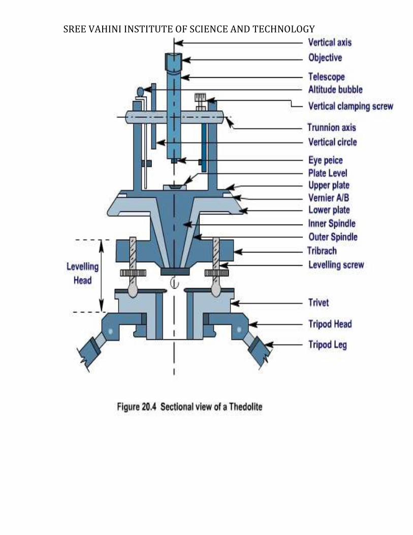
The permanent adjustments are to be done to maintain the required standard relationship between the fundamental lines (axes) of a Theodolite. The fundamental lines are as follows a. Vertical axis b. Horizontal axis or trunnion axis c. Line of collimation or line of sight d. Axis of plate level e. Axis of altitude level Required relations between the fundamental lines (axes)
� The axis of plate level must be perpendicular to the vertical axis. � The line of collimation must be perpendicular to the horizontal axis � The horizontal axis must be perpendicular to the vertical axis. � The axis of the altitude level must be parallel to the line of collimation. � The vernier reading of vertical circle must read zero when the line of
Collimation is horizontal. The permanent adjustments of a Theodolite are:
� Adjustment of plate level � Adjustment of line of sight � Adjustment of horizontal axis � Adjustment of altitude bubble and vertical index frame
Temporary adjustments The adjustments which are carried out at every setting of the instrument before the observations are referred as temporary adjustments. There are three types of temporary adjustments as follows.
� Setting up � Levelling up � Elimination of parallax
SREE VAHINI INSTITUTE OF SCIENCE AND TECHNOLOGY
a) Setting up
This adjustment includes the following two operations
� Centering the Theodolite over the instrument station � Approximate leveling of Theodolite with the help of the tripod legs only
Centering
It is the operation by which the vertical axis of the theodolite represented by a plumb line is made to pass through the mark of instrument station on the ground.
Approximate leveling
The approximate leveling may be done with the reference to a small circular bubble provided on the tribrach or by eye judgements
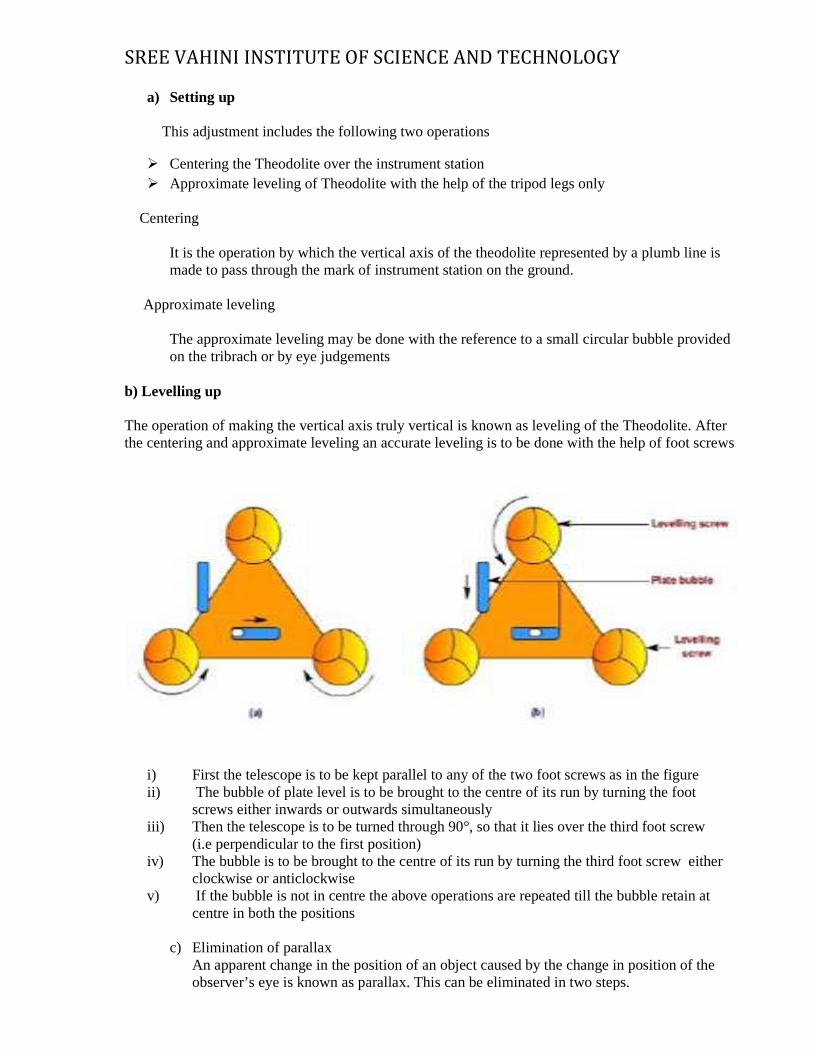
b) Levelling up
The operation of making the vertical axis truly vertical is known as leveling of the Theodolite. After the centering and approximate leveling an accurate leveling is to be done with the help of foot screws
i) First the telescope is to be kept parallel to any of the two foot screws as in the figure ii) The bubble of plate level is to be brought to the centre of its run by turning the foot
screws either inwards or outwards simultaneously iii) Then the telescope is to be turned through 90°, so that it lies over the third foot screw
(i.e perpendicular to the first position) iv) The bubble is to be brought to the centre of its run by turning the third foot screw either
clockwise or anticlockwise v) If the bubble is not in centre the above operations are repeated till the bubble retain at
centre in both the positions
c) Elimination of parallax An apparent change in the position of an object caused by the change in position of the observer’s eye is known as parallax. This can be eliminated in two steps.
SREE VAHINI INSTITUTE OF SCIENCE AND TECHNOLOGY
1) Focusing the eye piece for distinct vision of the cross hairs 2) Focusing the objective to bring the image of the object in the plane of cross hairs.
1) Focusing the eye piece
� The telescope is to be pointed towards the sky or a sheet of white paper is to be hold in front
of the objective. � The eye piece is to be moved in or out by rotating it gradually until the appearance of cross
hairs becomes sharp and distinct.
2) Focusing the objective
� Telescope is to be directed towards the object. � Focusing screw is to be turned until the appearance of the object becomes sharp and
clear.
RESULT:
Thus the study about the Temporary and Permanent adjustments of a Theodolite is practiced.
SREE VAHINI INSTITUTE OF SCIENCE AND TECHNOLOGY
EXPERIMENT NO: 2(A) DATE:
MEASUREMENT OF HORIZONTAL ANGLES
AIM To measure the horizontal angle by Repetition method with the use of Theodolite APPARATUS USED
1. Theodolite, 2. Ranging rods, 3. Pegs or Arrows
PROCEDURE
1. Theodolite is set over an instrument station (O) exactly and all the temporary
adjustments are done. Vertical circle is placed left to the observer (face left observation). 2. Vernier A is set to Zero with the help of upper clamp screw and tangent screws Readings of
Vernier A and B are noted 3. Upper clamp is clamped. Lower clamp is loosened and the telescope is turned towards “P”.
Lower clamp is clamped and the point “P” is bisected exactly using tangent screws 4. Both the vernier A and B are read and noted (Must be equal to 0° and 180° respectively).Upper
clamp is unclamped and the telescope is turned clockwise and “Q” is bisected. 5. Upper clamp is clamped and “Q” is bisected exactly using tangent screws. Both the verniers are
read. Mean of the readings provide an approximate included angle of POQ. 6. The reading of vernier A gives directly the angle POQ, and 180° is subtracted by the reading of
vernier B. The mean value of two readings gives the angle POQ with one face 7. Lower clamp is unclamped and the telescope is turned anticlockwise to sight P again. Lower
clamp is clamped and P is bisected exactly using tangent screws 8. Upper clamp is loosened and the telescope is turned clockwise and Q is bisected. Upper clamp is
clamped and Q is bisected exactly using tangent screws. The vernier now read twice the value of angle POQ.
9. Last two steps (7&8) are repeated once again to get the thrice value of angle POQ 10. Finally obtained reading is divided by 3 to get the mean value of angle POQ. 11. The face is changed and the whole process is repeated. (Face right observations). 12. Average value of two horizontal angles obtained with face left and face right observations is
determined.
SREE VAHINI INSTITUTE OF SCIENCE AND TECHNOLOGY
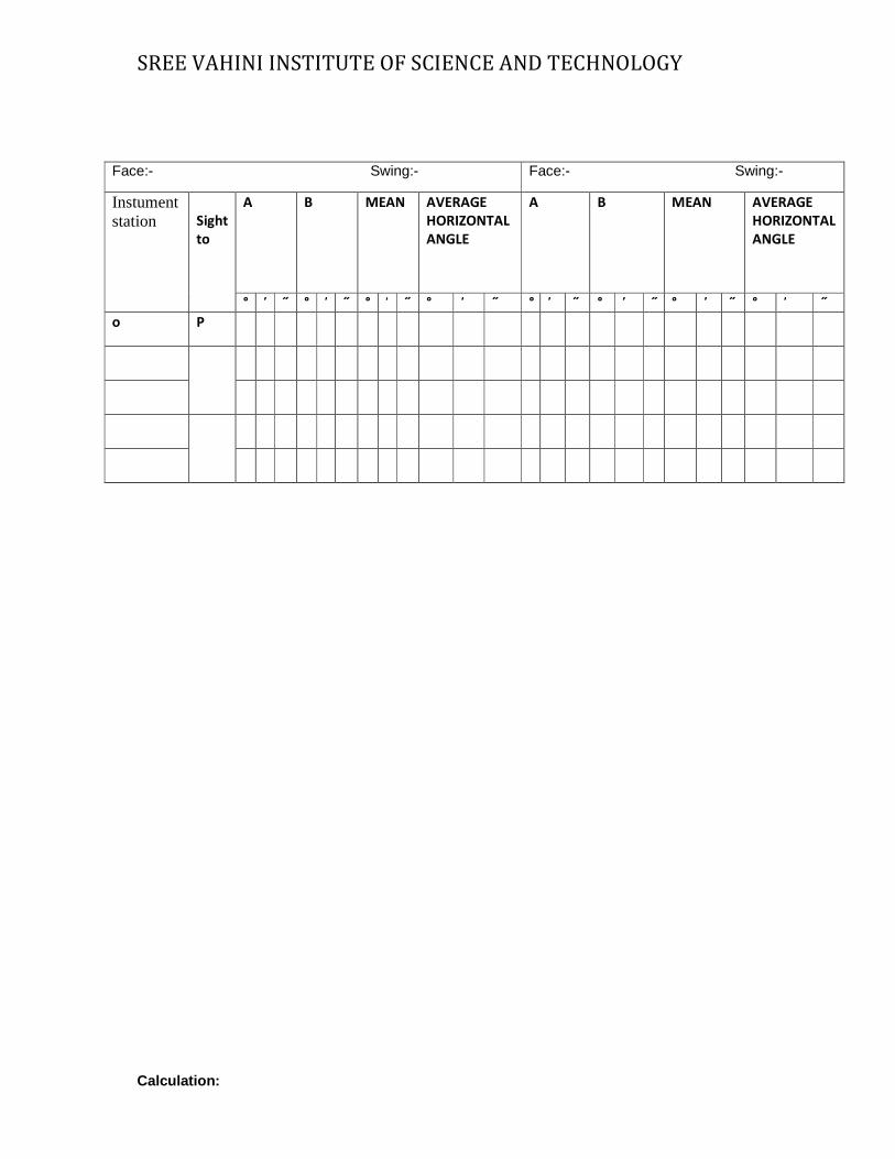
Calculation:
Face:- Swing:- Face:- Swing:-
Instument station
Sight
to
A B MEAN AVERAGE
HORIZONTAL
ANGLE
A B MEAN AVERAGE
HORIZONTAL
ANGLE
° ̕ ˝ ° ̕ ˝ ° ̕ ˝ ° ̕ ˝ ° ̕ ˝ ° ̕ ˝ ° ̕ ˝ ° ̕ ˝
o P
SREE VAHINI INSTITUTE OF SCIENCE AND TECHNOLOGY
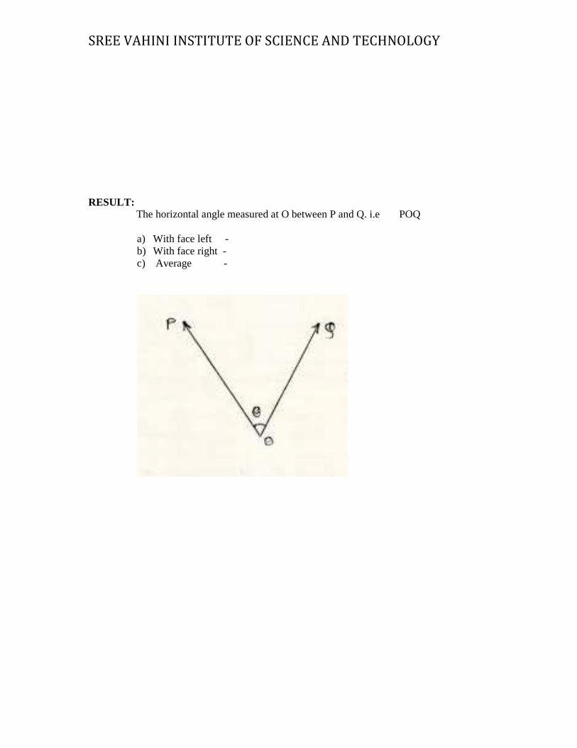
RESULT: The horizontal angle measured at O between P and Q. i.e ��POQ
a) With face left - b) With face right - c) Average -
SREE VAHINI INSTITUTE OF SCIENCE AND TECHNOLOGY
EXPERIMENT NO: 2(B) DATE:
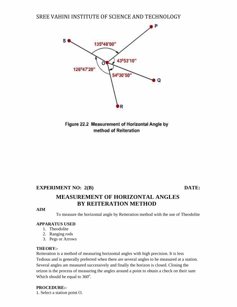
MEASUREMENT OF HORIZONTAL ANGLES BY REITERATION METHOD AIM
To measure the horizontal angle by Reiteration method with the use of Theodolite APPARATUS USED
1. Theodolite 2. Ranging rods 3. Pegs or Arrows
THEORY:- Reiteration is a method of measuring horizontal angles with high precision. It is less Tedious and is generally preferred when there are several angles to be measured at a station. Several angles are measured successively and finally the horizon is closed. Closing the orizon is the process of measuring the angles around a point to obtain a check on their sum Which should be equal to 360o. PROCEDURE:- 1. Select a station point O.
SREE VAHINI INSTITUTE OF SCIENCE AND TECHNOLOGY
2. Set the theodolite at O and do the temporary adjustments. The telescope is adjusted for right face right swing. 3. Set the vernier A to zero using upper clamp. Loosen the lower clamp, direct the telescope to the
station point A and bisect A exactly by using the lower clamp and lower tangent screw. 4. Note the vernier readings (A and B). 5. Loosen the upper clamp and turn the telescope clockwise until the point B is exactly bisected. 6. Note the vernier readings (A and B). 7. The mean of the two vernier readings gives the value of <AOB. 8. Bisect all the points successively and note the readings of both verniers at each bisection. 9. Finally close the horizon by sighting the station point A. The A vernier should be 3600. If not, note the closing error. 10. Adjust the telescope for left face left swing. 11. Repeat the whole process by turning the telescope in anticlockwise direction. 12. Distribute the closing error proportionately the several observed angles. 13. Take the average of face left and face right observations to give the corresponding horizontal angles.
Face:- Swing:- Face:- Swing:-
SREE VAHINI INSTITUTE OF SCIENCE AND TECHNOLOGY
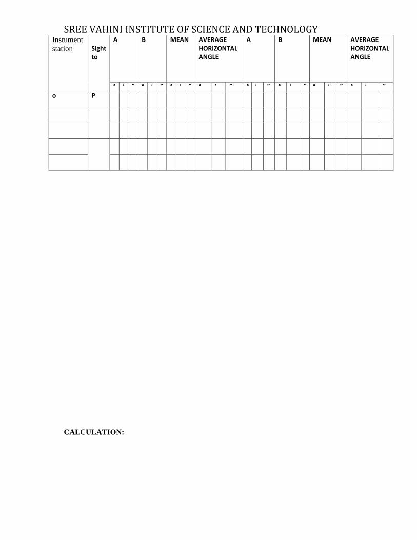
CALCULATION:
Instument station
Sight
to
A B MEAN AVERAGE
HORIZONTAL
ANGLE
A B MEAN AVERAGE
HORIZONTAL
ANGLE
° ̕ ˝ ° ̕ ˝ ° ̕ ˝ ° ̕ ˝ ° ̕ ˝ ° ̕ ˝ ° ̕ ˝ ° ̕ ˝
o P

SREE VAHINI INSTITUTE OF SCIENCE AND TECHNOLOGY
RESULT: The horizontal angle measured at O between P and Q. i.e ��POQ
a) With face left:- b) With face right:- c) Average:-
SREE VAHINI INSTITUTE OF SCIENCE AN
EXPERIMENT NO: 3
TRIGONOMETRIC LEVELING DISTANCES PROBLEM (TWO EXERCISES)
Aim:
To find the elevation of the top of a spire / tower / building using the principle of trigonometric leveling. Equipment:
Transit Vernier Theodolite, Tripod stand, Plumb bob, Tape, Leveling Staff and Pegs. Procedure:
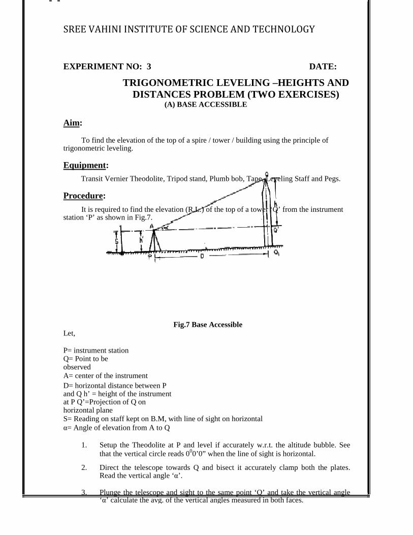
It is required to find the elevation (R.L.) of the top of a tower ‘Q’ from the instrument station ‘P’ as shown in Fig.7.
Let, P= instrument station Q= Point to be observed A= center of the instrument D= horizontal distance between P and Q h’ = height of the instrument at P Q’=Projection of Q on horizontal plane S= Reading on staff kept on B.M, with line of sight on horizontal α= Angle of elevation from A to Q
1. Setup the Theodolite at P and level if accurately w.rthat the vertical circle reads 0
2. Direct the telescope towards Q and bisect it accurately clamp both the plates.
Read the vertical angle ‘
3. Plunge the telescope and sight to the ‘α’ calculate the avg. of the vertical angles measured in both faces.
SREE VAHINI INSTITUTE OF SCIENCE AND TECHNOLOGY
TRIGONOMETRIC LEVELING –HEIGHTS AND DISTANCES PROBLEM (TWO EXERCISES)
(A) BASE ACCESSIBLE
To find the elevation of the top of a spire / tower / building using the principle of
Transit Vernier Theodolite, Tripod stand, Plumb bob, Tape, Leveling Staff and Pegs.
required to find the elevation (R.L.) of the top of a tower ‘Q’ from the instrument
Fig.7 Base Accessible
distance between P and Q h’ = height of the instrument
S= Reading on staff kept on B.M, with line of sight on horizontal = Angle of elevation from A to Q
Setup the Theodolite at P and level if accurately w.r.t. the altitude bubble. See that the vertical circle reads 000’0” when the line of sight is horizontal.
Direct the telescope towards Q and bisect it accurately clamp both the plates. Read the vertical angle ‘α’.
Plunge the telescope and sight to the same point ‘Q’ and take the vertical angle ’ calculate the avg. of the vertical angles measured in both faces.
D TECHNOLOGY
DATE:
HEIGHTS AND DISTANCES PROBLEM (TWO EXERCISES)
To find the elevation of the top of a spire / tower / building using the principle of
Transit Vernier Theodolite, Tripod stand, Plumb bob, Tape, Leveling Staff and Pegs.
required to find the elevation (R.L.) of the top of a tower ‘Q’ from the instrument
.t. the altitude bubble. See 0’0” when the line of sight is horizontal.
Direct the telescope towards Q and bisect it accurately clamp both the plates.
same point ‘Q’ and take the vertical angle
SREE VAHINI INSTITUTE OF SCIENCE AND TECHNOLOGY
take the reading on the leveling staff kept at A.B.M. Let it be ‘S’.
Observations and Calculations:
Vertical Angle, α = Staff Reading, S (m) = Horizontal Distance, D (m) =
From Triangle AQQ’: h = D tanα R.L. of Q (m) = R.L of B.M + S + h where h =
D tanα (Or) R.L. of Q (m) = R.L of instrument axis +
D tanα (Or) R.L. of Q (m) = R.L of P + h’ + D tanα, if R.L of P is Known
Result:
R.L. of Q (m) = R.L of B.M + S + h where h = D tanα
SREE VAHINI INSTITUTE OF SCIENCE AN
(B) BASE INACCESSIBLE (SINGLE PLANE METHOD)Aim:
To find the elevation of the top of a building using the principle of trigonometrically leveling with the instrument stations having their vertical axes in the same plane as the object. Equipment:
Transit Vernier Theodolite, Tripod Stand, Plumb Bob, Tape, Leveling Staff and Pegs. Procedure:
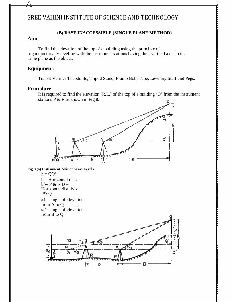
It is required to find the elevation (R.L.) of stations P & R as shown in Fig.8.
Fig.8 (a) Instrument Axis at Same Levels
h = QQ’ b = Horizontal dist. b/w P & R D = Horizontal dist. b/w P& Q α1 = angle of elevation from A to Q α2 = angle of elevation from B to Q
SREE VAHINI INSTITUTE OF SCIENCE AND TECHNOLOGY
(B) BASE INACCESSIBLE (SINGLE PLANE METHOD)
To find the elevation of the top of a building using the principle of leveling with the instrument stations having their vertical axes in the
Transit Vernier Theodolite, Tripod Stand, Plumb Bob, Tape, Leveling Staff and Pegs.
It is required to find the elevation (R.L.) of the top of a building ‘Q’ from the instrument P & R as shown in Fig.8.
Fig.8 (a) Instrument Axis at Same Levels
D TECHNOLOGY
leveling with the instrument stations having their vertical axes in the
Transit Vernier Theodolite, Tripod Stand, Plumb Bob, Tape, Leveling Staff and Pegs.
the top of a building ‘Q’ from the instrument
SREE VAHINI INSTITUTE OF SCIENCE AND TECHNOLOGY
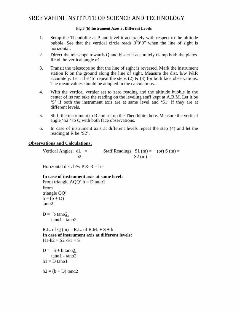
Fig.8 (b) Instrument Axes at Different Levels
1. Setup the Theodolite at P and level it accurately with respect to the altitude
bubble. See that the vertical circle reads 000’0” when the line of sight is horizontal.
2. Direct the telescope towards Q and bisect it accurately clamp both the plates. Read the vertical angle α1.
3. Transit the telescope so that the line of sight is reversed. Mark the instrument
station R on the ground along the line of sight. Measure the dist. b/w P&R accurately. Let it be ‘b’ repeat the steps (2) & (3) for both face observations. The mean values should be adopted in the calculations.
4. With the vertical vernier set to zero reading and the altitude bubble in the
center of its run take the reading on the leveling staff kept at A.B.M. Let it be ‘S’ if both the instrument axis are at same level and ‘S1’ if they are at different levels.
5. Shift the instrument to R and set up the Theodolite there. Measure the vertical
angle ‘α2 ‘ to Q with both face observations.
6. In case of instrument axis at different levels repeat the step (4) and let the reading at R be ‘S2’.
Observations and Calculations:
Vertical Angles, α1�= Staff Readings S1 (m) = (or) S (m) = α2 = S2 (m) =
Horizontal dist. b/w P & R = b =
In case of instrument axis at same level: From triangle AQQ’ h = D tanα1 From triangle QQ’ h = (b + D) tanα2 D = b tanα2.
tanα1 - tanα2
R.L. of Q (m) = R.L. of B.M. + S + h In case of instrument axis at different levels: H1-h2 = S2~S1 = S
D = S + b tanα2.
tanα1 - tanα2 h1 = D tanα1
h2 = (b + D) tanα2
SREE VAHINI INSTITUTE OF SCIENCE AN
R.L. of Q = R.L. of B.M. + S1 + h1
R.L. of Q = RL of B.M. + S2 + h2Result:
R.L. of given point Q (m) =EXPERIMENT NO: 4
HEIGHTS AND DISTANCE US
TACHEOMETRIC
Aim:
To determine the Tacheometric constants using Tacheometer. Equipment:
Tacheometer, Chain (or) Tape, Pegs and Levelling Staff. Principle:
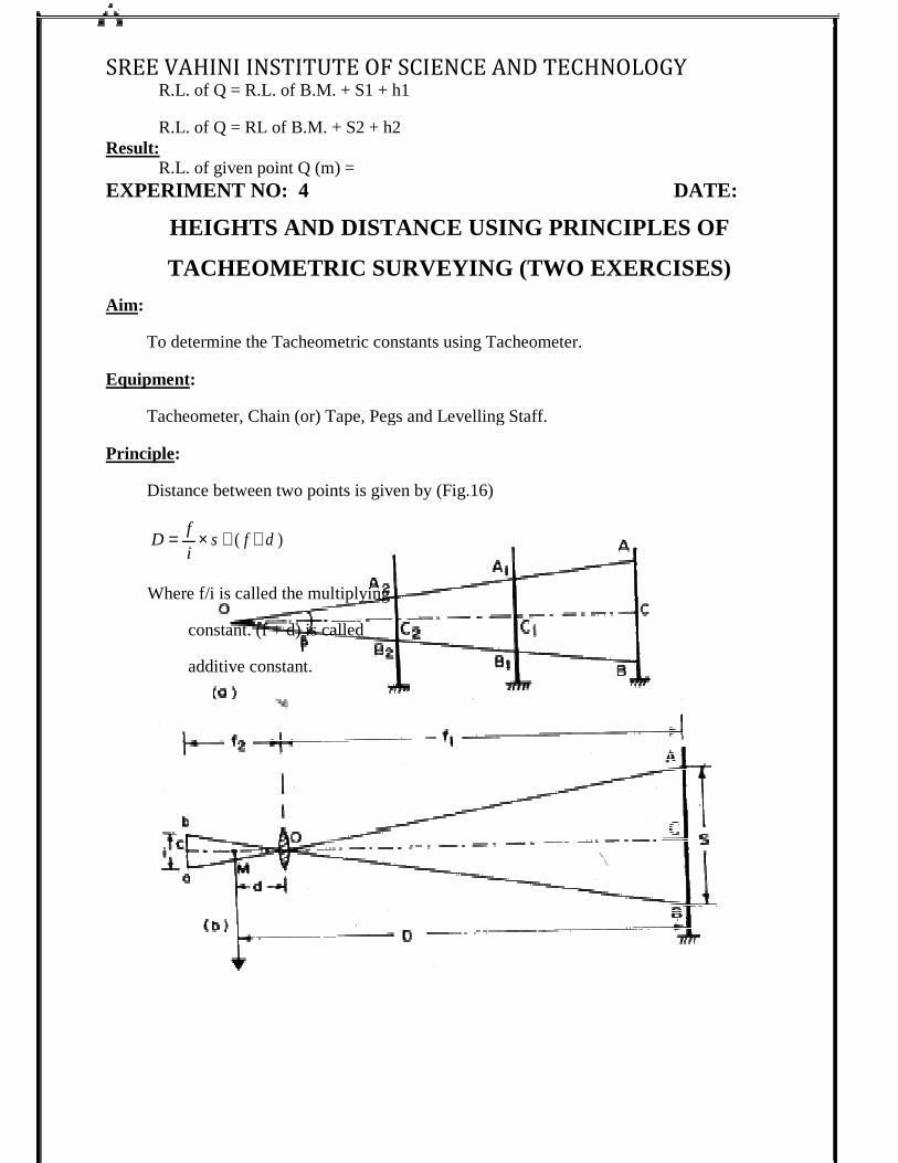
Distance between two points is given by (Fig.16)
D = f × s + ( f + d )
i
Where f/i is called the multiplying
constant. (f + d) is called
additive constant.
SREE VAHINI INSTITUTE OF SCIENCE AND TECHNOLOGY
R.L. of Q = R.L. of B.M. + S1 + h1
R.L. of Q = RL of B.M. + S2 + h2
R.L. of given point Q (m) =
HEIGHTS AND DISTANCE US ING PRINCIPLES OF
TACHEOMETRIC SURVEYING (TWO EXERCISES)
To determine the Tacheometric constants using Tacheometer.
(or) Tape, Pegs and Levelling Staff.
Distance between two points is given by (Fig.16)
Where f/i is called the multiplying
constant. (f + d) is called
D TECHNOLOGY
DATE:
ING PRINCIPLES OF
SURVEYING (TWO EXERCISES)
SREE VAHINI INSTITUTE OF SCIENCE AND TECHNOLOGY
Fig.16 Tachometric Constants
Procedure: 1. Setup the instrument at one end of a straight line say 50m
2. Drive pegs at 10m, 20m, and 25m and at 50m lengths...
3. Keep the staff on the pegs and observe the corresponding staff intercepts with horizontal sight.
4. Knowing the values of ‘S’ and corresponding ‘D’ values for different peg intervals a number of similar equations can be formed by substituting the values of ‘S’ and ‘D’ in equation
a. D = KS + C
5. The simultaneous equations are taken two at a time to find the values of ‘K’ and ‘C’.
6. The average values of ‘K’ and ‘C’ are found.
Observations and Calculations:
Horizontal Distance, D (m) =
Staff Intercept, S (m) =
D = KS + C Result:
For the given instrument
f/i = multiplying constant (K) =
f+d = Additive constant (C) =
SREE VAHINI INSTITUTE OF SCIENCE AND TECHNOLOGY
EXPERIMENT NO: 5 DATE:
CURVE SETTING- DIFFERENT METHODS.
(TWO EXERCISES)
(A) SETTING OUT A SIMPLE CURVE BY MEANS OF OFFSETS FROM LONG CHORD
Aim:
To setout the simple curve of given radius and length of long chord by means of offsets from the long chord. Equipment:
Theodolite, Tripod Stand, Cross-Staff, Ranging Rods, Pegs, Chain and Tape. Principle:
Setting out a curve by method of offsets from long chord is linear method. It involves setting out the normal offsets of the long chord at specified intervals and joining them.
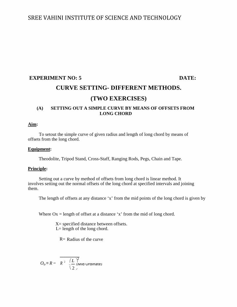
The length of offsets at any distance ‘x’ from the mid points of the long chord is given by
Where Ox = length of offset at a distance ‘x’ from the mid of long chord. X= specified distance between offsets.
L= length of the long chord. R= Radius of the curve
Oo = R − R 2 L 2
−
(Mid Ordinate)
2
SREE VAHINI INSTITUTE OF SCIENCE ANUsually, the offsets from the mid of long chord towards the end are setout and the
curve is symmetric over the central offset line. Procedure:
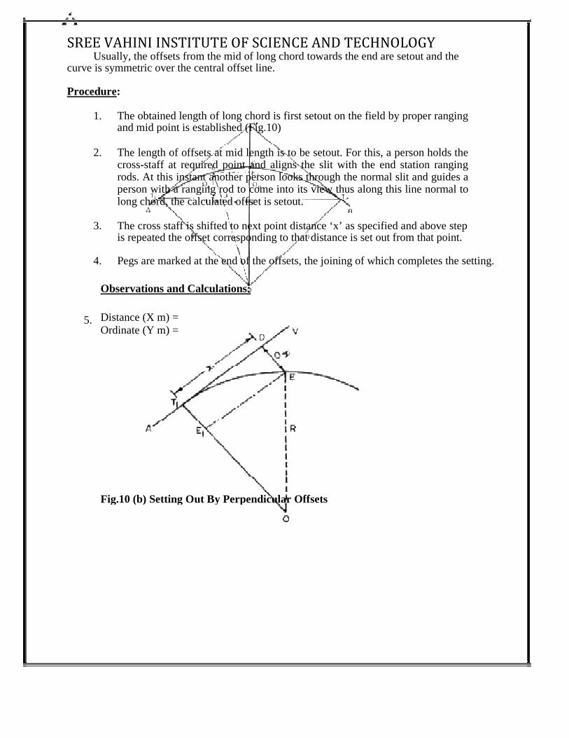
1. The obtained length of long chord is first setout on the field by proper ranging and mid point is established (Fig.10)
2. The length of offsets at mid length is to be setout. For this, a person holds the
cross-staff at required point and aligns the slit witrods. At this instant another person looks through the normal slit and guides a person with a ranging rod to come into its view thus along this line normal to long chord, the calculated offset is setout.
3. The cross staff is shifted to next point distance ‘x’ as specified and above step
is repeated the offset corresponding to that distance is set out from that point.
4. Pegs are marked at the end of the offsets, the joining of which completes the setting. Observations and Calculations: Distance (X m) = 5. Ordinate (Y m) = Fig.10 (b) Setting Out By Perpendicular Offsets
SREE VAHINI INSTITUTE OF SCIENCE AND TECHNOLOGYUsually, the offsets from the mid of long chord towards the end are setout and the
curve is symmetric over the central offset line.
The obtained length of long chord is first setout on the field by proper ranging and mid point is established (Fig.10)
The length of offsets at mid length is to be setout. For this, a person holds the staff at required point and aligns the slit with the end station ranging
rods. At this instant another person looks through the normal slit and guides a person with a ranging rod to come into its view thus along this line normal to long chord, the calculated offset is setout.
The cross staff is shifted to next point distance ‘x’ as specified and above step is repeated the offset corresponding to that distance is set out from that point.
Pegs are marked at the end of the offsets, the joining of which completes the setting.
bservations and Calculations:
Fig.10 (b) Setting Out By Perpendicular Offsets
D TECHNOLOGY
Usually, the offsets from the mid of long chord towards the end are setout and the
The obtained length of long chord is first setout on the field by proper ranging
The length of offsets at mid length is to be setout. For this, a person holds the h the end station ranging
rods. At this instant another person looks through the normal slit and guides a person with a ranging rod to come into its view thus along this line normal to
The cross staff is shifted to next point distance ‘x’ as specified and above step is repeated the offset corresponding to that distance is set out from that point.
Pegs are marked at the end of the offsets, the joining of which completes the setting.
SREE VAHINI INSTITUTE OF SCIENCE AN
Result: The simple curve is setout by the method of offsets from long chord in the field.
Applications: Curves are used on highways and railways where it is necessary to change the direction of motion.
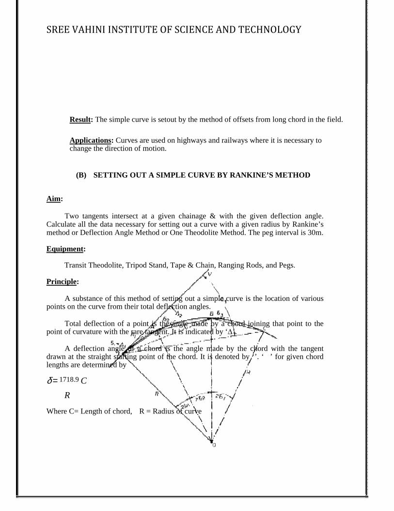
(B) SETTING OUT A SIMPLE CURVE BY RANKINE’S METHOD Aim:
Two tangents intersect at a given chainage & with the given deflection angle. Calculate all the data necessary for setting out a curve with a given radius by Rankine’s method or Deflection Angle Method or One Theodolite Method. The peg interval is 30m. Equipment:
Transit Theodolite, Tripod Stand, Tape & Chain, Ranging Rods, and Pegs. Principle:
A substance of this method of setting out a simple curve is the location of various points on the curve from their total deflection angles.
Total deflection of a point is the angle made by a chord joining that point to the point of curvature with the rare tangent. It is indicated by ‘
A deflection angle of a chord is the angle made by the chord with the tangent drawn at the straight starting point of the chord. It is denoted by ‘’. ‘lengths are determined by
δ = 1718.9 C
R Where C= Length of chord, R = Radius of curve
SREE VAHINI INSTITUTE OF SCIENCE AND TECHNOLOGY
The simple curve is setout by the method of offsets from long chord in the field.
Curves are used on highways and railways where it is necessary to direction of motion.
SETTING OUT A SIMPLE CURVE BY RANKINE’S METHOD
Two tangents intersect at a given chainage & with the given deflection angle. data necessary for setting out a curve with a given radius by Rankine’s
method or Deflection Angle Method or One Theodolite Method. The peg interval is 30m.
Transit Theodolite, Tripod Stand, Tape & Chain, Ranging Rods, and Pegs.
substance of this method of setting out a simple curve is the location of various points on the curve from their total deflection angles.
Total deflection of a point is the angle made by a chord joining that point to the tangent. It is indicated by ‘∆’.
A deflection angle of a chord is the angle made by the chord with the tangent drawn at the straight starting point of the chord. It is denoted by ‘’. ‘�’ for giv
R = Radius of curve
D TECHNOLOGY
The simple curve is setout by the method of offsets from long chord in the field.
Curves are used on highways and railways where it is necessary to
SETTING OUT A SIMPLE CURVE BY RANKINE’S METHOD
Two tangents intersect at a given chainage & with the given deflection angle. data necessary for setting out a curve with a given radius by Rankine’s
method or Deflection Angle Method or One Theodolite Method. The peg interval is 30m.
Transit Theodolite, Tripod Stand, Tape & Chain, Ranging Rods, and Pegs.
substance of this method of setting out a simple curve is the location of various
Total deflection of a point is the angle made by a chord joining that point to the
A deflection angle of a chord is the angle made by the chord with the tangent � iven chord
SREE VAHINI INSTITUTE OF SCIENCE AND TECHNOLOGY
Procedure:
1. Locate points T1, T2 and V (Fig.11).
2. Setup the Theodolite exactly at point T1 and make its temporary adjustments.
3. Set the ‘A’ – vernier to zero degrees and bisect the point V, clamp the lower plate.
4. Release the upper plate and set the ‘A’-vernier to read ∆1 the line of sight is thus directed along T1 A.
5. Hold the zero of the tape at T1 & take a distance C1 (T1A) and swing the tape
with an arrow till it is bisected by the Theodolite. This establishes the first point A on the curve.
6. Set the second deflection angle ∆2 on the vernier so that the line of sight is set along
T1B.
7. Hold the zero of the tape at point A and an arrow at the other end (AB), swing the tape about point A till the arrow is bisected at point B. This establishes the second point B on the curve.
8. The same steps are repeated till the last point T2 is reached.
Observations and Calculations:
δ = 1718.9
C = deflection angle, δ1 , δ2 , δ3 … etc., are the successive deflection angles R
Where C = Length of chord, C1, C2,…etc., are the successive chord lengths R = Radius of curve
Let ABCD ….. be the points on the curve the total deflection angles of which are ∆1 ∆2 ∆3 …
SREE VAHINI INSTITUTE OF SCIENCE AND TECHNOLOGY
then
∆1 = δ1
∆2 = ∆1 + δ2 ---------------------- ---------------------- ----------------------
And ∆n = ∆n-1 + δn Length of Long Chord L = 2R SIN ∆/2 Tangent length (T1V) = R Tan ∆/2 Length of Curve = R ∆ (∆/180) Chainage of point T1 = Chainage of V – T1V Chainage of point T2 = Chainage of T1 + Length of Curve
Result:
The required simple circular curve is set out in the field by Rankine’s Method.
SREE VAHINI INSTITUTE OF SCIENCE AND TECHNOLOGY
EXPERIMENT NO: 6 DATE:
SETTING OUT WORKS FOR
BUILDINGS AND PIPE LINES
AIM To set out the foundation marking for the proposed construction of building. APPARATUS USED
1. Theodolite 2. Ranging rods 3. Pegs or Arrows 4. String.
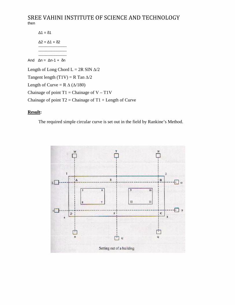
THEORY:- Setting out of a building involves the transfer of the architect‘s plan from paper onto the actual site. The object of setting out a building is to provide the builder with clearly defined outlines for excavations. Two methods are generally used for setting out a building. PROCEDURE:- 1. A centre line sketch of the building is prepared. (The centres of cross walls are also to
SREE VAHINI INSTITUTE OF SCIENCE AND TECHNOLOGY
be indicated.) 2. The base line is set out with reference to given reference points. 3. The ends of the centre line of the walls, points A and B from the base line are marked. 4. As the end marks A,B,C,etc. are disturbed during excavation, stakes are fixed at L,M,N etc., a little away (about 2 to 3 m) for end mark and tied accurately using a string. 5. The centre line for all other walls AD,BC,etc are marked by dropping perpendicular.
For small buildings the perpendiculars may be set out by using a chain or a tape by ‘3-
4-5’ method. For an important and big building when sides are long a Theodolite may be employed to accurately set out the perpendiculars and to range the lines. 6. For every wall, the pegs are driven a little away for marking the end and tied accurately using a string. 7. Diagonals are measured and checked with their corresponding calculated lengths. 8. Width of foundation from the centerline are marked and the corners 1,2,3,4,5 etc., are fix up. Pegs are driven at these corners. The cord is stretched and lime is spread along the chords. RESULT: Thus the trench plan being marked on the ground, and excavation may be started.
EXPERIMENT NO: 7 DATE:
DETERMINE OF AREA USING TOTAL STATION
AIM: To determine the given plot’s surface area. APPARATUS:
1. Total station 2. Prism with other accessories.
THEORY: The computations of areas and volumes is often required in civil engineering practice. One of primary aims of land surveying is to determine the are of land under survey. Which is usually the property of an individual or institution. In plane surveying the team “area” refers to the orthogonal projection of ground on a horizontal plane, not actual the ground surface. PROCEDURE:
SREE VAHINI INSTITUTE OF SCIENCE AND TECHNOLOGY
(a) Make a quick ‘eye ball’ plan view sketch of the map area in the field book. This will b e an important reference to which you will later append information such as the location of home stations, back sights etc.
(b) Take a few minutes to walk around your map area figure out where the optional places for home stations, back sights and transverses are.
(c) Select a suitable location and setup instrument and do all necessary station adjustments and job selection.
(d) Allocate the [Area] soft key to [meas] mode screen.
(e) Press [Area] to begin surface area calculation.
(i) Sight the first point on the line enclosing the area and press [meas].
(ii) Press [OBs] to begin observation. The measured values are displayed. The [OBs] function requires each point to be observed individually before area calculation is performed.
(iii) When [Read] is pressed registered co-ordinates can be recalled and used in subsequent measurement.
(iv) Press [ok] to enter the values of point.
(f) Repeat ‘d’ until all the points have been measured. Points on the enclosed area are observed in a clock wise or counter clock wise direction.
(g) After all the points necessary to calculate the surface area have observed press [calc] to display calculated area. (h) Press (ok) to quit area calculation and return to [MEAS] mode. RESULT: The area of given points is _____________ m2.
EXPERIMENT NO: 8 DATE:
TRAVERSING USING TOTAL STATION
Aim:
To do a closed traversing for at least five points using Total Station. Equipment:
1. Total Station 2. Tripod
3. Prism and Pole 4. Arrows
SREE VAHINI INSTITUTE OF SCIENCE AN
5. Field Book Procedure:
1. Identify the points on the ground for traversing and mark them arrows.
2. Choose a control point for using it as first station point such that at least one control point for back
3. Set up the instrument on the point chosen in step 2.
4. Press MENU
5. Press F1 (Programs)
6. Press F1 (Survey).
7. For Setting up the job as you know the coordinates of two control points
on the paper follow the following steps.
8. Press F1 (Set Job).
9. Press F1 (New).
10. Enter the New Job Name by pressing
11. Give the name of the job by using the Function key
12. Press F4 (OK).
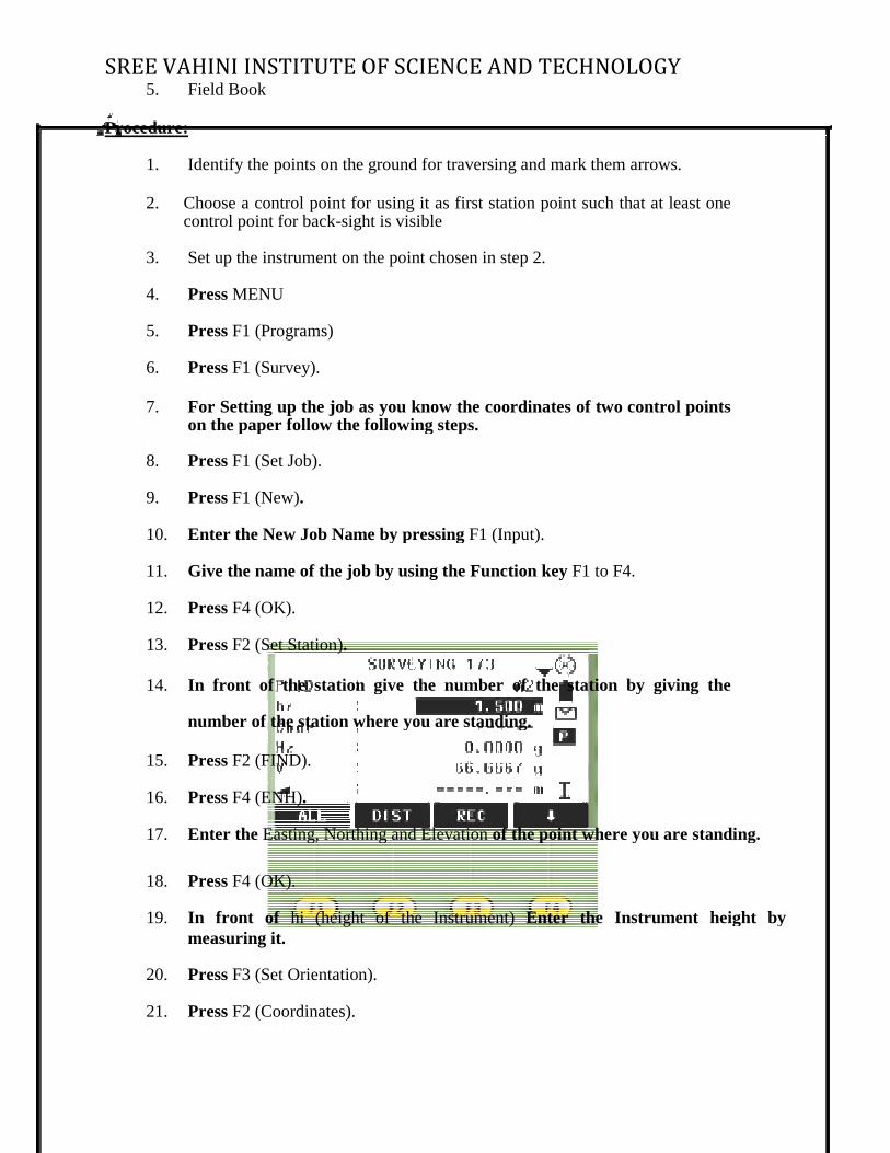
13. Press F2 (Set Station)
14. In front of the station give the number of the station by giving the
number of the station where you are standing.
15. Press F2 (FIND).
16. Press F4 (ENH).
17. Enter the Easting, Northing and Elevation
18. Press F4 (OK).
19. In front of hi (height of the Instrument)
measuring it.
20. Press F3 (Set Orientation).
21. Press F2 (Coordinates).
SREE VAHINI INSTITUTE OF SCIENCE AND TECHNOLOGY
Identify the points on the ground for traversing and mark them arrows.
Choose a control point for using it as first station point such that at least one control point for back-sight is visible
Set up the instrument on the point chosen in step 2.
F1 (Programs)
For Setting up the job as you know the coordinates of two control points on the paper follow the following steps.
Enter the New Job Name by pressing F1 (Input).
Give the name of the job by using the Function key F1 to F4.
F2 (Set Station).
In front of the station give the number of the station by giving the
number of the station where you are standing.
Easting, Northing and Elevation of the point where you are standing.
hi (height of the Instrument) Enter the Instrument height by
F3 (Set Orientation).
F2 (Coordinates).
D TECHNOLOGY
Identify the points on the ground for traversing and mark them arrows.
Choose a control point for using it as first station point such that at least one
For Setting up the job as you know the coordinates of two control points
In front of the station give the number of the station by giving the
of the point where you are standing.
Enter the Instrument height by
SREE VAHINI INSTITUTE OF SCIENCE AND TECHNOLOGY
22. In front of BS (Back Sight) Enter the number of the back sight point to which you are aligning.
23. Press F4 (ENH).
24. Press F4 (OK).
25. Press PAGE.
26. Press F4 until you have DIST In front of F1.
27. The value in front of gives the relative error in the station shifting.
28. Press F2 (REC).
29. Press F4 (NO).
Press F4 (Start)
31. Take foresight on first traverse point enter point ID and record its coordinates. (This point will be the next instrument station)
32. Shift the instrument to first traverse point and follow the standard procedure
to obtain the coordinates of second traverse point.
33. Continue until you finish all traverse points.
34. Check whether there is any closing error. If it is there apply corrections to the coordinate and plot the traverse.
(If you are using advanced instruments closing error will be shown automatically in traverse report and traverse can be adjusted on board)
Result:
SREE VAHINI INSTITUTE OF SCIENCE AND TECHNOLOGY
Record the coordinates obtained for each point in your field book. If there is a closing error apply correction to all the coordinates. Plot the survey on a drawing sheet using the corrected coordinates. Applications:
In control surveys and topographical surveys it is required to do traversing. In control surveys, using the existing control points it is required to establish new control points. In topographical surveys using the existing control points and also by establishing new control points it is required obtain the coordinates of various details like buildings, roads and other features
EXPERIMENT NO: 9 DATE:
CONTOURING USING TOTAL STATION
Aim:
To prepare Contour map of an area using Total Station
SREE VAHINI INSTITUTE OF SCIENCE AND TECHNOLOGY
Equipment:
1. Total Station 2. Tripod
3. Prism and Pole 4. Arrows 5. Field Book
Procedure:
1. Obtain the coordinates of all the grid points and record them in your field book
2. Choose a control point from where all the grid points and at least one control point for back-sight are visible.
3. Set up the instrument on the point chosen in step 2.
4. Press MENU
5. Press F1 (Programs)
6. Press F2 (Stake Out).
7. For Setting up the job as you know the coordinates of two control points
on the paper follow the following steps.
8. Press F1 (Set Job).
9. Press F1 (New).
10. Enter the New Job Name by pressing F1 (Input).
11. Give the name of the job by using the Function key F1 to F4.
12. Press F4 (OK).
13. Press F2 (Set Station).
14. In front of the station give the number of the station by giving the number of the station where you are standing.
15. Press F2 (FIND).
16. Press F4 (ENH).
17. Enter the Easting, Northing and Elevation of the point where you are standing.
18. Press F4 (OK).
SREE VAHINI INSTITUTE OF SCIENCE AN
19. In front of hi (height of the Instrument) 20. Press F3 (Set Orientation).
21. Press F2 (Coordinates).
22. In front of BS (Back Sight) Enter the number of the back sight point to
which you are aligning. 23. Press F4 (ENH).
24. Press F4 (OK).
25. Press PAGE.
26. Press F4 until you have
27. The value in front of gives the relative error in the station shifting.
28. Press F2 (REC).
29. Press F4 (NO).
30. Press F4 (Start).
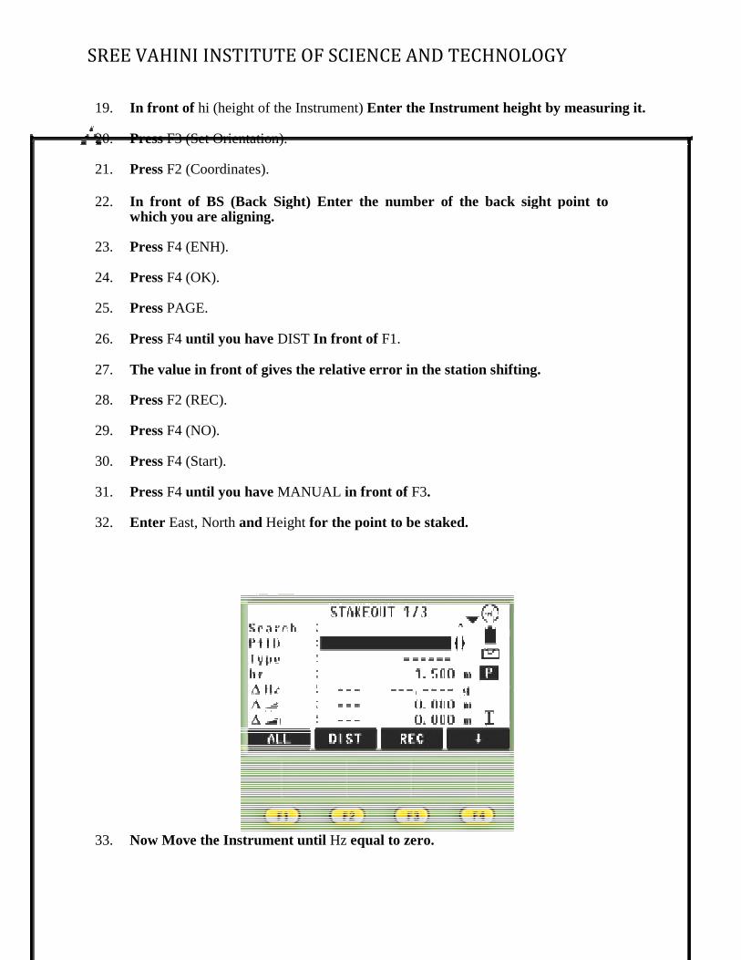
31. Press F4 until you have
32. Enter East, North and Height
33. Now Move the Instrument until
SREE VAHINI INSTITUTE OF SCIENCE AND TECHNOLOGY
hi (height of the Instrument) Enter the Instrument height by measuring it.
F3 (Set Orientation).
In front of BS (Back Sight) Enter the number of the back sight point to which you are aligning.
until you have DIST In front of F1.
The value in front of gives the relative error in the station shifting.
until you have MANUAL in front of F3.
Height for the point to be staked.
Now Move the Instrument until Hz equal to zero.
D TECHNOLOGY
Enter the Instrument height by measuring it.
In front of BS (Back Sight) Enter the number of the back sight point to
SREE VAHINI INSTITUTE OF SCIENCE AND TECHNOLOGY
34. Now move the prism in this line of sight to the distance given in front of
from the instrument station. 35. Now with moving the instrument horizontally with moving the telescope up
and down only tells the prism man to come in line of sight of that point. Again Press F2 (DIST) do this until the value comes near to the limiting factor and you have the point. Then press All or trigger button to record the point.
Result:
Record the coordinates of all the points surveyed in your field book and using this data create a contour map of the area surveyed.
Applications:
In topographical surveys, it is required to obtain contour maps/ plans of an area. Contour maps are useful in planning and construction of pipeline works, road works and residential colonies etc.
SREE VAHINI INSTITUTE OF SCIENCE AND TECHNOLOGY
EXPERIMENT NO: 10 DATE:
DETERMINATION OF REMOTE HEIGHT USING TOTAL STATION
AIM: To determine remote height of object whose top is in accessible APPARATUS:
1. Total station 2. Prism with other accessories. 3.
THEORY: A Rem measurement is a function used to measure the elevation of a point where a target cannot be directly installed power line, over had cables and bridges etc. PROCEDURE: 1. Select a suitable location and set up instrument and do all necessary adjustment and job selection.
2. Allocate the Rem soft key to the Meas mode screen.
3. Select the target directly or directly over the object and measure target height with total station.
4. After inputting the height measured accurately sight the target. Press Dist in page of meas mode to carry out measurement. The measured distance data, vertical angle and horizontal angle displayed. Press stop to stop measurement.
5. Sight object and then press Rem. The REM measurement is started and height from the ground to object is displayed in ‘Ht’.
6. Press stop to terminate the measurement operation.
7. To Re observe the object, sight the target, then press OBS.
8. Press (ESC) to finish and return to the MEAS mode screen. RESULT: The elevation of given water tank = 1.45 + 20.045 m = 21.49m.
SREE VAHINI INSTITUTE OF SCIENCE AND TECHNOLOGY
EXPERIMENT NO: 11 DATE:
STAKE OUT USING TOTAL STATION
Aim: To set out column centres of a proposed building. Equipment:
1. Total Station
2. Tripod
3. Prism and Pole
4. Arrows 5. Field Book
Procedure:
1. Obtain the coordinates of all the column centers.
2. Choose a control point from where all column positions and at least one control point for back-sight are visible.
3. Set up the instrument on the point chosen in step 2.
4. Press MENU
5. Press F1 (Programs)
6. Press F2 (Stake Out).
7. For Setting up the job as you know the coordinates of two control points on the
paper follow the following steps.
8. Press F1 (Set Job).
9. Press F1 (New).
10. Enter the New Job Name by pressing F1 (Input).
11. Give the name of the job by using the Function key F1 to F4.

SREE VAHINI INSTITUTE OF SCIENCE AND TECHNOLOGY
12. Press F4 (OK).
13. Press F2 (Set Station).
14. In front of the station give the number of the station by giving the number of the station where you are standing.
15. Press F2 (FIND).
16. Press F4 (ENH).
17. Enter the Easting, Northing and Elevation of the point where you are standing.
18. Press F4 (OK).
19. In front of hi (height of the Instrument) Enter the Instrument height by measuring it. 20. Press F3 (Set Orientation).
21. Press F2 (Coordinates).
22. In front of BS (Back Sight) Enter the number of the back sight point to which
you are aligning.
23. Press F4 (ENH).
24. Press F4 (OK).
25. Press PAGE.
26. Press F4 until you have DIST In front of F1.
27. The value in front of gives the relative error in the station shifting.
28. Press F2 (REC).
29. Press F4 (NO).
30. Press F4 (Start).
31. Press F4 until you have MANUAL in front of F3. Enter East, North and Height for the point to be staked.\
33. Now Move the Instrument until Hz equal to zero.
34. Now move the prism in this line of sight to the distance given in front of from the instrument station.
35. Now with moving the instrument horizontally with moving the telescope up and
down only tell the prism man to come in line of sight of that point. Again Press F2 (DIST) do this until the value comes near to the limiting factor and you have the

SREE VAHINI INSTITUTE OF SCIENCE AND TECHNOLOGY
point.
36. For the next point again Press F4 until you have manual in front of F3 and again enter the coordinates of the next point to be staked repeat this process for all the points.
Result: :
Record the details of points set out in your field book. Applications: In setting out a building, a surveyor has to set out position of columns and other elements of the building in both horizontal and vertical planes.
SREE VAHINI INSTITUTE OF SCIENCE AN EXPERIMENT NO 12
DISTANCE, GRADIENT AND DIFFERENCE OF HEIGHT BETWEEN TWOINACCESSIBLE POINTS USING TOTAL STATION
Aim : To obtain the distance, gradient and difference of height between two in the Total Station. Equipment:
1. Total Station
2. Tripod
3. Prism and Pole
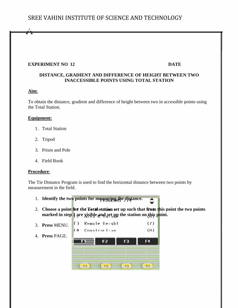
4. Field Book Procedure: The Tie Distance Program is used to find the horizontal distance between two points by measurement in the field.
1. Identify the two points for measuring the distance.
2. Choose a point for the Total station set up such that from this point the two points marked in step 1 are visible and set up the station on this point.
3. Press MENU.
4. Press PAGE.
SREE VAHINI INSTITUTE OF SCIENCE AND TECHNOLOGY
DATE
DISTANCE, GRADIENT AND DIFFERENCE OF HEIGHT BETWEEN TWOINACCESSIBLE POINTS USING TOTAL STATION
To obtain the distance, gradient and difference of height between two in accessible points using
The Tie Distance Program is used to find the horizontal distance between two points by
Identify the two points for measuring the distance.
Choose a point for the Total station set up such that from this point the two points marked in step 1 are visible and set up the station on this point.
D TECHNOLOGY
DATE
DISTANCE, GRADIENT AND DIFFERENCE OF HEIGHT BETWEEN TWO
accessible points using
The Tie Distance Program is used to find the horizontal distance between two points by
Choose a point for the Total station set up such that from this point the two points
SREE VAHINI INSTITUTE OF SCIENCE AN
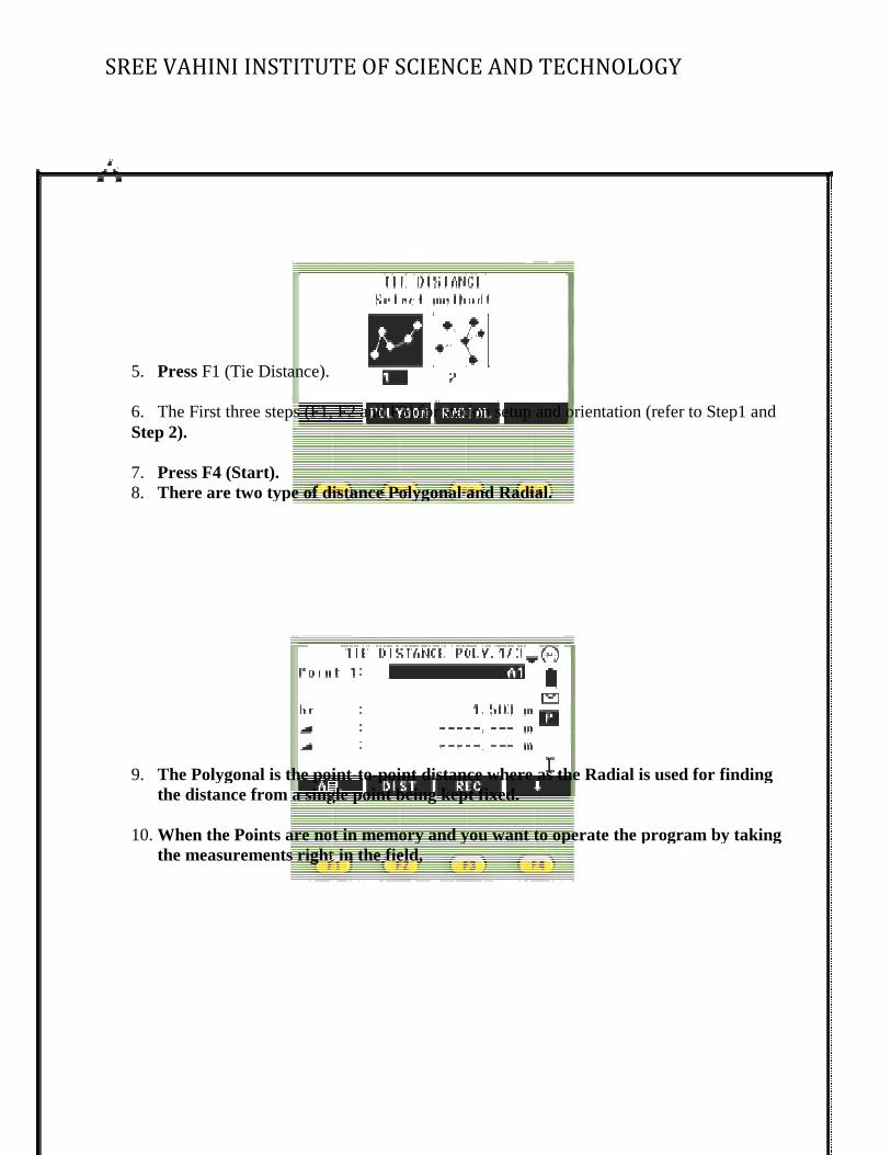
5. Press F1 (Tie Distance).
6. The First three steps (F1, F2 and F3) for station setup and orientation (refer to Step1 and Step 2).
7. Press F4 (Start). 8. There are two type of distance Polygonal and Radial.
9. The Polygonal is the pointthe distance from a single point being kept fixed.
10. When the Points are not in memory and you want to operate the program by taking
the measurements right in the field,
SREE VAHINI INSTITUTE OF SCIENCE AND TECHNOLOGY
The First three steps (F1, F2 and F3) for station setup and orientation (refer to Step1 and
There are two type of distance Polygonal and Radial.
The Polygonal is the point-to-point distance where as the Radial is used for finding the distance from a single point being kept fixed.
When the Points are not in memory and you want to operate the program by taking the measurements right in the field,
D TECHNOLOGY
The First three steps (F1, F2 and F3) for station setup and orientation (refer to Step1 and
point distance where as the Radial is used for finding
When the Points are not in memory and you want to operate the program by taking
SREE VAHINI INSTITUTE OF SCIENCE AND TECHNOLOGY
11. In front of the point enter the number of the point and Press F3 (ALL).
12. In front of the point2 Enter the number of the second point again sight it and press F3 (ALL).
13. Now you can see the results displayed on the screen. Result: The distance (d), gradient (s) and difference of height (h) between two in accessible points are, d = , s = , h = Applications: In topographical surveys, some times features like buildings etc. are not accessible. Therefore a surveyor should be familiar with the technique of obtaining the horizontal distance, difference in height and hence the gradient between two inaccessible points.