SR–1 STEERING - Turboninjas.com STEERING PRINCIPLES Power steering is a hydraulic device which...
73
STEERING – STEERING SR–1
Transcript of SR–1 STEERING - Turboninjas.com STEERING PRINCIPLES Power steering is a hydraulic device which...

STEERING–STEERING
SR–1

GENERAL DESCRIPTION• Care must be taken to replace parts properly because they could affect the performance of
the steering system and result in a driving hazard.• The steering wheel pad has an airbag built in, so take all due precautions when handling it. For
more details, see the SUPPLEMENTAL RESTRAINT SYSTEM (SRS) section.
TROUBLESHOOTINGUse the table below to help you find the cause of the problem.The numbers indicate the priority of the likely cause of the problem. Check each parts in order. Ifnecessary, replace these parts.
Sus
pens
ion
arm
bal
l joi
nts
(Wor
n)
Fro
nt w
heel
alig
nmen
t (In
corr
ect)
Ste
erin
g sy
stem
join
ts (
Wor
n)
Fro
nt w
heel
bea
ring
(Wor
n)
Ste
erin
g co
lum
n (B
indi
ng)
Tire
s (im
prop
erly
infla
ted)
Ste
erin
g ge
ar h
ousi
ng
Slid
ing
yoke
(W
orn)
Driv
e be
lt (L
oose
)
Flu
id le
vel (
Low
)
Abnormal noise
Excessive play
Hard steering
SA
–63,
72
PartsName
Poor return
See page
Trouble
SA
–10
SR
–24
SR
–24
SA
–4
SA
–4
–STEERING GENERAL DESCRIPTIONSR–2

ON–VEHICLE INSPECTIONCHECK THAT STEERING WHEEL FREEPLAY IS COR–RECTWith the vehicle stopped and tires pointed straightahead, rock the steering wheel gently back and forthwith light finger pressure.Freeplay should not exceed the maximum.Maximum freeplay:
30 mm (1.18 In.)If incorrect, repair.
–STEERING ON–VEHICLE INSPECTIONSR–3

(09237–00010) Water Pump Bearing Remover &Replacer
(09904–00050) No. 4 Claw
STEERING COLUMN
SST (SPECIAL SERVICE TOOLS)
09309–37010 Transmission Bearing Replacer
09236–00101 Water Pump Overhaul Tool Set
RECOMMENDED TOOLS
09612–22011 Tilt Handle Bearing Replacer
09213–31021 Crankshaft Pulley Puller
PREPARATION
09042–00010 Torx Socket T30
09904–00010 Expander Set
EQUIPMENT
Steering wheel pad
Torque wrench
Steering wheel
–STEERING STEERING COLUMNSR–4

ASSEMBLY REMOVAL ANDINSTALLATIONRemove and install the parts, as shown.
–STEERING STEERING COLUMNSR–5
2. REMOVE STEERING WHEEL PAD(a) Place the front wheels facing straight ahead.(b) Remove the No.2 and No.3 covers.(c) Using a torx wrench, loosen the screws.Produced by TMC: 3 screwsProduced by TMM: 2 screwsTorx wrench: T30 (Part No. 09042–00010 or locallymanufactured tool)HINT: Loosen the torx screws until groove along thescrew circumference catches on the screw case.
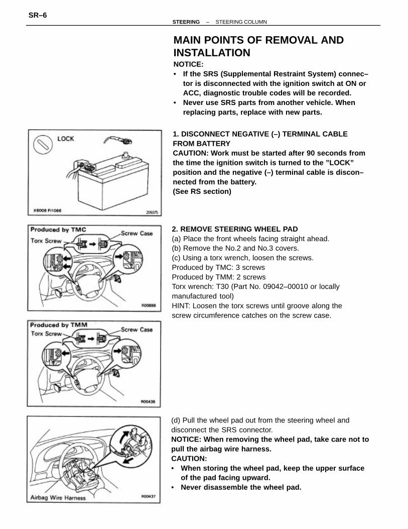
MAIN POINTS OF REMOVAL ANDINSTALLATIONNOTICE:• If the SRS (Supplemental Restraint System) connec–
tor is disconnected with the ignition switch at ON orACC, diagnostic trouble codes will be recorded.
• Never use SRS parts from another vehicle. Whenreplacing parts, replace with new parts.
(d) Pull the wheel pad out from the steering wheel anddisconnect the SRS connector.NOTICE: When removing the wheel pad, take care not topull the airbag wire harness.CAUTION:• When storing the wheel pad, keep the upper surface
of the pad facing upward.• Never disassemble the wheel pad.
1. DISCONNECT NEGATIVE (–) TERMINAL CABLEFROM BATTERYCAUTION: Work must be started after 90 seconds fromthe time the ignition switch is turned to the ”LOCK”position and the negative (–) terminal cable is discon–nected from the battery.(See RS section)
–STEERING STEERING COLUMNSR–6

5. INSTALL STEERING WHEEL PAD(a) Connect the SRS connector.(b) Install the wheel pad after confirming that the circum–ference groove of the torx screws is caught on thescrew case.(c) Using a torx wrench, tighten the screws.Produced by TMC: 3 screwsProduced by TMM: 2 screwsTorque: 8.8 N–m (90 kgf–cm, 78 in–lbf)NOTICE:• Make sure the wheel pad is installed to the specified
torque.• If the wheel pad has been dropped, or there are
cracks, dents or other defects in the case or connec–tor, replace the wheel pad with a new one.
• When installing the wheel pad, take care that thewirings do not interfere with other parts and are notpinched between other parts.
(d) Install the No.2 and No.3 covers.
3. REMOVE STEERING WHEEL(a) Disconnect the connector.(b) Remove the set nut.(c) Place matchmarks on the steering wheel and mainshaft.(d) Using SST, remove the steering wheel.SST 09213–31021
4. INSTALL STEERING WHEEL(a) Align matchmarks on the steering wheel and mainshaft, and install the wheel to the shaft.(b) Tighten the wheel set nut.Torque: 35 N–m (360 kgf–cm, 26 ft–lbf)(c) Connect the connector.
–STEERING STEERING COLUMNSR–7

6. CHECK STEERING WHEEL CENTER POINT AFTERINSTALLING STEERING COLUMN7. CONNECT NEGATIVE (–) TERMINAL CABLE TOBATTERY
–STEERING STEERING COLUMNSR–8

STEERING COLUMNCOMPONENTS
–STEERING STEERING COLUMNSR–9

2. REMOVE COLUMN UPPER BRACKET(a) Using a centering punch, mark the center of the 2tapered–head bolts.(b) Using a 3–4 mm (0.12–0.16 in.) drill, drill into the 2tapered–head bolts.
(c) Using a screw extractor, remove the 2 tapered–headbolts.(d) Remove the column upper clamp bracket and thecolumn tube.
STEERING COLUMN DISASSEMBLY1. REMOVE IGNITION KEY CYLINDER ILLUMINATION
3. ALIGN STEERING COLUMNAlign the upper column tube and lower column tube.
4. REMOVE MAIN SHAFT(a) Using snap ring pliers, remove the snap ring.
–STEERING STEERING COLUMNSR–10

(d) Using SST, set the steering column on a press, asshown.SST 09236 –00101 (09237–00010)
(e) Using a brass bar, press out the main shaft.NOTICE: To prevent damage to the main shaft avoiddropping it.
5. REMOVE MAIN SHAFT COLLAR AND BUSHING(a) Remove the collar from the main shaft.(b) Using snap ring pliers, remove the snap ring.
(b) Using a screwdriver, loosen the staked parts of theupper column tube.
(c) Using a plastic hammer, tap the main shaft until themain stopper contacts the collar.
–STEERING STEERING COLUMNSR–11

2. IF NECESSARY, REPLACE KEY CYLINDER(a) Place the ignition key at the ACC position.(b) Push down the stop pin with a thin rod, and pull outthe key cylinder.(c) Make sure the ignition key is at the ACC position.(d) Install a new key cylinder.
3. INSPECT UPPER BEARINGCheck the upper bearing condition by manually turn–ing the load bearing surface inside the column tube.If there is resistance to turning, or an uneven force isrequired to turn the bearing surface, replace thecolumn tube.
STEERING COLUMN INSPECTION ANDREPLACEMENT1. INSPECT STEERING LOCK OPERATIONCheck that the steering lock mechanism operates pro–perly.
4. INSPECT LOWER BEARINGCheck the lower bearing condition by manually turn–ing the load bearing surface outside the main shaft.If there is resistance to turning, or an uneven force isrequired to turn the bearing surface, replace the mainshaft.
(c) Using a brassbar, tap the bushing off the main shaft.
–STEERING STEERING COLUMNSR–12

5. (A/T)INSPECT KEY INTERLOCK SOLENOID(See AX section)6. (A/T)IF NECESSARY, REPLACE KEY INTERLOCK SOLE–NOID(a) Remove the 2 screws and the solenoid.(b) Install a new solenoid with the 2 screws.
STEERING COLUMN ASSEMBLY1. COAT ALL RUBBING PARTS WITH MOLYBDENUMDISULPHIDE LITHIUM BASE GREASE2. INSTALL MAIN SHAFT BUSHING AND COLLAR(a) Using SST, tap the bushing onto the main shaft.SST 09612–22011
(e) Using SST, tap in the collar to the column tube.SST 09309–37010
(b) Using snap ring pliers, install the snap ring.(c) Install the collar on the bushing.
(d) Insert the main shaft in the column tube.
–STEERING STEERING COLUMNSR–13
3. INSTALL UPPER BRACKET(a) Install the upper bracket with 2 new tapered–headbolts.(b) Tighten the 2 tapered–head bolts until the bolt headbreaks off.4. INSTALL IGNITION KEY CYLINDER ILLUMINATION
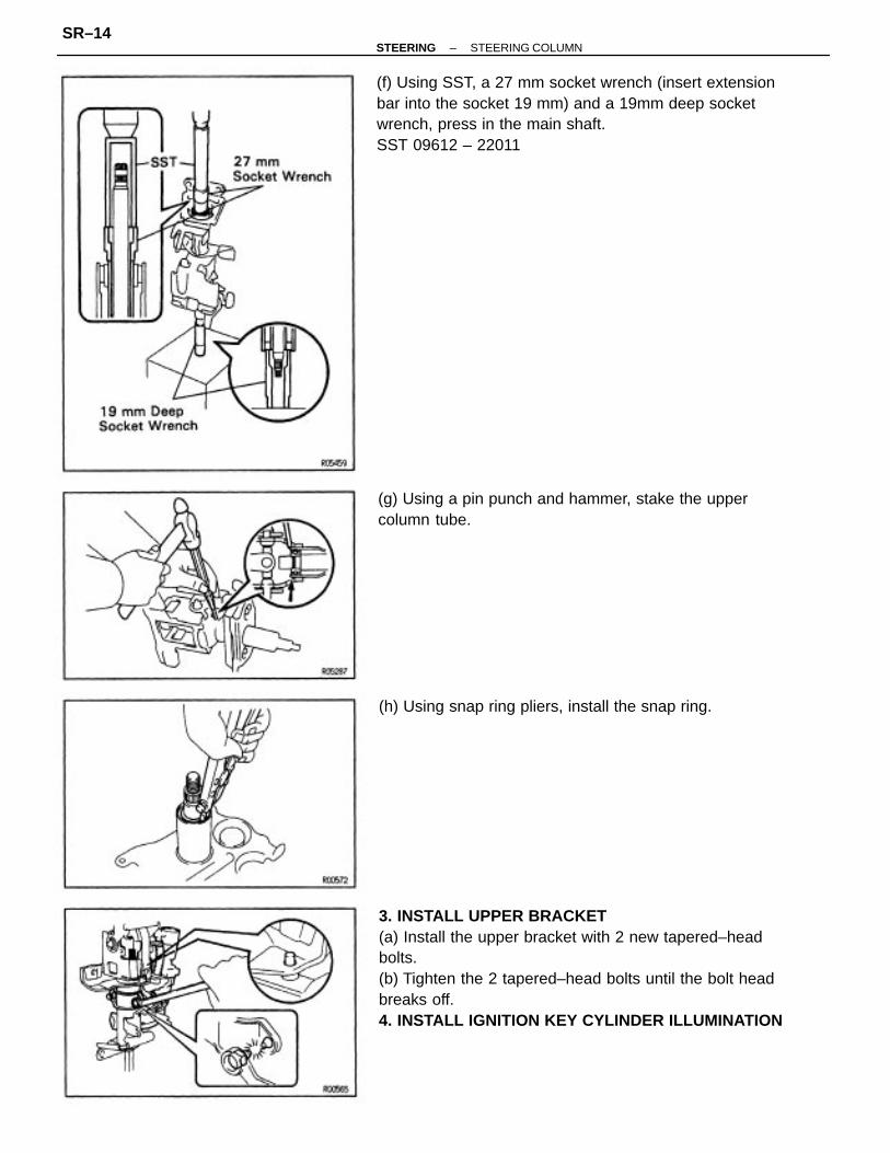
(f) Using SST, a 27 mm socket wrench (insert extensionbar into the socket 19 mm) and a 19mm deep socketwrench, press in the main shaft.SST 09612 – 22011
(g) Using a pin punch and hammer, stake the uppercolumn tube.
(h) Using snap ring pliers, install the snap ring.
–STEERING STEERING COLUMNSR–14

POWER STEERING PRINCIPLESPower steering is a hydraulic device which utilizes engine power to reduce steering effort.Consequently, the engine is used to drive a pump to develop fluid pressure, and this pressure actson a piston within the power cylinder so that the piston assists the rack effort. The amount of thisassistance depends on the extent of pressure acting on the piston. Therefore, if more steeringforce is required, the pressure must be raised. The variation in the fluid pressure is accomplishedby a control valve which is linked to the steering main shaft.
NEUTRAL (STRAIGHT–AHEAD) POSITIONFluid from the pump is sent to the control valve. If the control valve is in the neutral position, allthe fluid will flow through the control valve into the relief port and back to the pump. At this time,hardly any pressure is created and because the pressure on the cylinder piston is equal on bothsides, the piston will not move in either direction.
POWER STEERING
DESCRIPTION
–STEERING POWER STEERINGSR–15
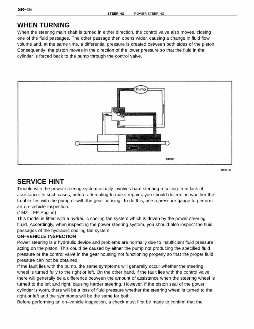
SERVICE HINTTrouble with the power steering system usually involves hard steering resulting from lack ofassistance. In such cases, before attempting to make repairs, you should determine whether thetrouble lies with the pump or with the gear housing. To do this, use a pressure gauge to performan on–vehicle inspection.(1MZ – FE Engine)This model is fitted with a hydraulic cooling fan system which is driven by the power steeringflu,id. Accordingly, when inspecting the power steering system, you should also inspect the fluidpassages of the hydraulic cooling fan system.ON–VEHICLE INSPECTIONPower steering is a hydraulic device and problems are normally due to insufficient fluid pressureacting on the piston. This could be caused by either the pump not producing the specified fluidpressure or the control valve in the gear housing not functioning properly so that the proper fluidpressure can not be obtained.If the fault lies with the pump, the same symptoms will generally occur whether the steeringwheel is turned fully to the right or left. On the other hand, if the fault lies with the control valve,there will generally be a difference between the amount of assistance when the steering wheel isturned to the left and right, causing harder steering. However, if the piston seal of the powercylinder is worn, there will be a loss of fluid pressure whether the steering wheel is turned to theright or left and the symptoms will be the same for both.Before performing an on–vehicle inspection, a check must first be made to confirm that the
WHEN TURNINGWhen the steering main shaft is turned in either direction, the control valve also moves, closingone of the fluid passages. The other passage then opens wider, causing a change in fluid flowvolume and, at the same time, a differential pressure is created between both sides of the piston.Consequently, the piston moves in the direction of the lower pressure so that the fluid in thecylinder is forced back to the pump through the control valve.
–STEERING POWER STEERINGSR–16

VANE PUMPThe main component parts of the vane pump, such as the cam ring, rotor, vanes and flow controlvalve are high precision parts and must be handled carefully. Also, because this pump producesa very high fluid pressure, 0–rings are used for sealing each part. When reassembling the pump,always use new 0 – rings.In the flow control valve, there is a relief valve which controls the maximum pressure of the pump.The amount of this maximum pressure is very important; if it is too low, there will be insufficientpower steering assistance and if too high, it will have an adverse effect on the pressure hoses, oilseals, etc. If the maximum pressure is either too high or too low due to a faulty relief valve, do notdisassemble or adjust the relief valve, but replace the flow control valve as an assembly.The clearance between the flow control valve and pump body installation hole is very important.After manufacture, the factory measures the size of the installation hole and outer circumferenceof the flow control valve, and punches a mark accordingly. Therefore, when replacing the flowcontrol valve, be sure to do so with one having the same mark in order to ensure the properclearance.
power steering system is completely free of any air. If there is any air in the system, the volumeof this air will change when the fluid pressure is raised, causing a fluctuation in the fluid pressureso that the power steering will not function properly. To determine if there is any air in thesystem, check if there is a change of fluid level in the reservoir tank when the steering wheel isturned fully to the right or left.If there is air in the system, it will be compressed to a smaller volume when the steering wheel isturned, causing a considerable drop in the fluid level. If the system is free of air, there will be verylittle change in the level even when the fluid pressure is raised. This is because the fluid, being aliquid, does not change volume when compressed. The small change in the fluid level is due toexpansion of the hoses between the pump and gear housing when pressure rises.Also, air in the system sometimes causes abnormal noise in the pump or gear housing when thesteering wheel is fully turned in either direction.This on–vehicle inspection must be performed every time after overhauling or repairing thepump or gear housing to ensure that the power steering system is working properly.
–STEERING POWER STEERINGSR–17

The functional parts of the pump which produce fluid pressure are the cam ring, rotor and vanes,and these should be checked for wear. If the clearance between each is not within standard whenreassembling, any worn parts should be replaced.In this case, the replaced cam ring and rotor should be of the same length (have the same mark),and the vanes should be replaced with those having a length corresponding to that mark,otherwise the proper thrust clearance cannot be obtained. If there is too much thrust clearance,there will be insufficient fluid pressure at low speeds. If there is too little thrust clearance, it mayresult in seizure of the vanes.
GEAR HOUSINGIf the gear housing is secured directly in a vise during overhaul, there is danger of deforming it,so always first secure it in the SST provided (rack and pinion steering rack housing stand) beforeplacing it in the vise.
The oil seals on both sides of the power cylinder are for the prevention of leakage of the highpressure fluid which acts on the piston. Always use new oil seals when reassembling and be verycareful not to scratch or damage them.
–STEERING POWER STEERINGSR–18

Because of the high pressure, even the slightest scratch will cause fluid leakage, resulting in aninoperative power steering system.Also, be very careful not to scratch the sliding portion of the rack which makes contact with theoil seals. When removing the rack ends from the rack, it is very easy to cause a burr when holdingthe tip of the rack with a wrench. Therefore, before assembling the rack, first check the tip forburrs and remove any with an oil stone.Teflon rings are used for the piston and control valve. These teflon rings are highly durableagainst wear, but if it is necessary to replace them, be careful not so stretch the new ones. Afterinstalling a teflon ring into its groove, snug it down into the groove before assembly of thecylinder or housing to prevent possible damage.As with the rack and pinion type steering, preload is very important. If the preload is not correct,it could result in such trouble as steering wheel play or shimmy or lack of durability, so alwaysmake sure that it is correct.
The pump produces the maximum fluid pressure when the steering wheel is turned fully to theright or left and, at this time, there is a maximum load on the pump which causes a decrease inengine idle rpm. To solve this problem, vehicles are equipped with an idle– up device which actsto raise the engine idle rpm whenever there is a heavy load on the pump.On EFI engines, when the piston of the air control valve is pushed by fluid pressure, the air valveopens and the volume of air by–passing the throttle valve is increased to regulate engine rpm.
IDLE–UP DEVICE
–STEERING POWER STEERINGSR–19

PREPARATIONSST (SPECIAL SERVICE TOOLS)
(09617–24020) Steering Pinion BearingAdjusting Screw Lock Nut Wrench
(09613–22011) Steering Rack Shaft BushingPuller
09612–22011 Tilt Handle Bearing Replacer
09608–12010 Front Hub & Drive Pinion BearingReplacer Set
09238–47012 Water Pump Bearing Remover &Replacer
(09617–24030) Steering Rack End Wrench
09616–00010 Steering Worm Bearing AdjustingSocket
09616–30020 Steering Worm Bearing AdjustingScrew Wrench
(09608–00080) Replacer
09612–24014 Steering Gear Housing OverhaulTool Set
09612–00012 Rack & Pinion Steering RackHousing Stand
09620–30010 Steering Gear Box Replacer Set
09617–14010 Steering Rack End Wrench
PS pump bearing (3VZ–FE)
Gear housing oil seal
Control valve oil seal
–STEERING POWER STEERINGSR–20

(09623–30010) Steering Worm Bearing & Oil SealReplacer
(09631 –00020) Handle
(09620–24010) Valve Cup Oil Seal Remover
(09620–24020) Valve Cup Oil Seal Replacer
09631–22020 Power Steering Hose Nut14 x 17 mm Wrench Set
09631–16010 Cylinder End Stopper Nut Wrench
09631–12071 Steering Rack Oil Seal Test Tool
09630–24013 Steering Rack Oil Seal Tool Set
09631–33010 Steering Rack Cover ”I”
09631–10021 Rack Stopper Wrench
09631 –10030 Oil Seal Remover
09628–62011 Ball Joint Puller
09631–20081 Seal Ring Tool
09631 –12020 Handle
Tie rod end
–STEERING POWER STEERINGSR–21

POWER STEERING PUMP(1 MZ–FE)POWER STEERING PUMP REMOVAL ANDINSTALLATIONRemove and install the parts, as shown.
–STEERING POWER STEERINGSR–22

11. REMOVE CONTROL VALVE HOUSING(a) Remove the dust cover.(b) Place matchmarks on the valve housing and rackhousing.(c) Remove the 2 bolts.(d) Pull out the valve with the valve housing.(e) Remove the gasket from the rack housing.
(b) Using a screwdriver, pry a part the clasp of the No.2bracket.(c) Remove the bushing and bracket from the rack hous–ing.(d) Remove the bushing from the bracket.
10. REMOVE SELF– LOCKING NUTUsing SST to hold the control valve, remove the self–locking nut.SST 09616 – 00010
13. REMOVE N0.2 BRACKET(a) Place matchmarks on the bracket and rack housing.
12. REMOVE CONTROL VALVE FROM HOUSINGTap out the control valve and oil seal.
–STEERING POWER STEERINGSR–23

ON–VEHICLE INSPECTIONDRIVE BELT TENSION CHECKUsing a belt tension gauge, check the drive belt ten–sion.Belt tension gauge:
Nippondenso BTG–20 (95506–00020) orBorroughs No.BT–33–73F
Drive belt tension:1 MZ–FENew belt
667–824 N (68–84 kgf, 150–185 lbf)Used belt
422–598 N (43–61 kgf, 95–135 lbf)5S–FENew belt
441–667 N (45–68 kgf, 100–150 lbf)Used belt
275–441 N (28–45 kgf,60–100 lbf)HINT:• ”New belt’” refers to a belt which has been less
than 5 minutes on a running engine.• ”Used belt’ refers to a belt which has been used
on a running engine for 5 minutes or more.• After installing the drive belt, check that it fits
properly in the ribbed grooves.
FLUID LEVEL CHECK1. KEEP VEHICLE LEVEL2. BOOST FLUID TEMPERATUREWith the engine idling at 1,000 rpm or less, turn thesteering wheel from lock to lock several times toboost fluid temperature.Fluid temperature:
80�C (176�F)
3. CHECK FOR FOAMING OR EMULSIFICATIONHINT: Foaming and emulsification indicate either theexistence of air in the system or that the fluid level istoo low.4. CHECK FLUID LEVEL IN OIL RESERVOIRCheck the fluid level and add fluid if necessary.Fluid:
ATF DEXRON�ll
–STEERING POWER STEERINGSR–24
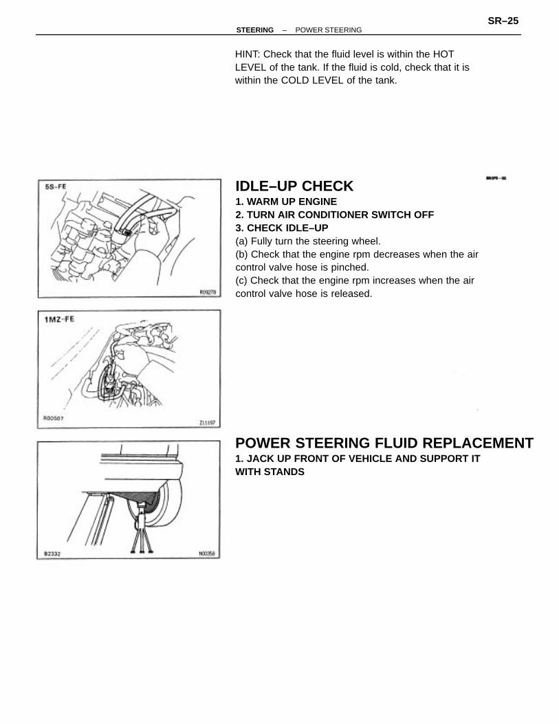
IDLE–UP CHECK1. WARM UP ENGINE2. TURN AIR CONDITIONER SWITCH OFF3. CHECK IDLE–UP(a) Fully turn the steering wheel.(b) Check that the engine rpm decreases when the aircontrol valve hose is pinched.(c) Check that the engine rpm increases when the aircontrol valve hose is released.
POWER STEERING FLUID REPLACEMENT1. JACK UP FRONT OF VEHICLE AND SUPPORT ITWITH STANDS
HINT: Check that the fluid level is within the HOTLEVEL of the tank. If the fluid is cold, check that it iswithin the COLD LEVEL of the tank.
–STEERING POWER STEERINGSR–25

4. FILL OIL RESERVOIR WITH FRESH FLUIDFluid:
ATF DEXRON�II
2. REMOVE FLUID RETURN HOSE FROM OIL RESER–VOIR AND DRAIN FLUID INTO CONTAINER
3. TURN STEERING WHEEL FROM LOCK TO LOCKWHILE DRAINING FLUID
–STEERING POWER STEERINGSR–26
POWER STEERING SYSTEM BLEEDING1. CHECK FLUID LEVEL IN OIL RESERVOIRCheck the fluid level and add fluid if necessary.Fluid:
ATF DEXRON� llHINT: Check that the fluid level is within the HOTLEVEL of the dipstick of the oil reservoir. If the fluid iscold, check that it is within the COLD LEVEL of thedipstick.2. START ENGINE AND TURN STEERING WHEELFROM LOCK TO LOCK 3 OR 4 TIMESWith the engine speed below 1,000 rpm, turn thesteering wheel to left or right full lock and keep itthere for 2–3 seconds, then turn the wheel to theopposite full lock and keep it there for 2–3 seconds.
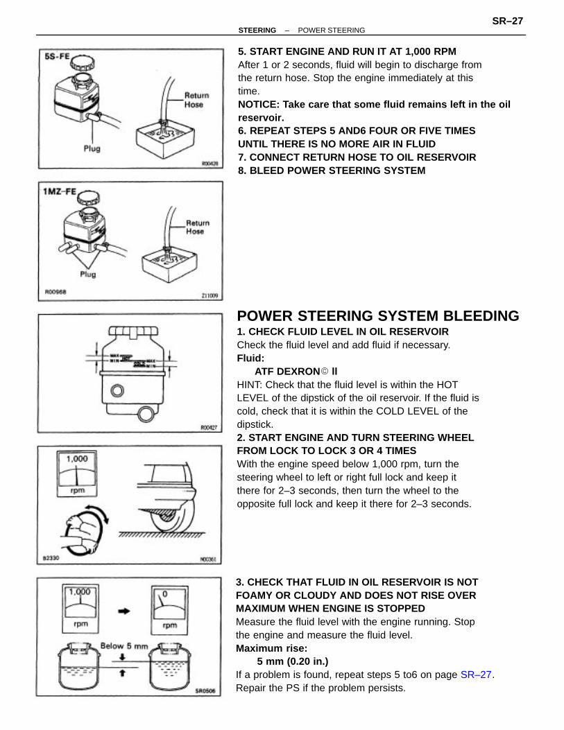
5. START ENGINE AND RUN IT AT 1,000 RPMAfter 1 or 2 seconds, fluid will begin to discharge fromthe return hose. Stop the engine immediately at thistime.NOTICE: Take care that some fluid remains left in the oilreservoir.6. REPEAT STEPS 5 AND6 FOUR OR FIVE TIMESUNTIL THERE IS NO MORE AIR IN FLUID7. CONNECT RETURN HOSE TO OIL RESERVOIR8. BLEED POWER STEERING SYSTEM
3. CHECK THAT FLUID IN OIL RESERVOIR IS NOTFOAMY OR CLOUDY AND DOES NOT RISE OVERMAXIMUM WHEN ENGINE IS STOPPEDMeasure the fluid level with the engine running. Stopthe engine and measure the fluid level.Maximum rise:
5 mm (0.20 in.)If a problem is found, repeat steps 5 to6 on page SR–27. Repair the PS if the problem persists.
–STEERING POWER STEERINGSR–27

4. START ENGINE AND RUN IT AT IDLE5. BOOST FLUID TEMPERATUREWith the engine idling at 1,000 rpm or less, turn thesteering wheel from lock to lock several times toboost fluid temperature.Fluid temperature: 80 �C (176 �F)
OIL PRESSURE CHECK1. CONNECT OIL PRESSURE GAUGE1 MZ–FE(a) Using SST, disconnect the pressure line joint.SST 09631 –22020
(b) Connect the gauge side of the pressure gauge to thePS pump side and the valve side to the gear housingside.2. BLEED POWER STEERING SYSTEM(See page SR–27)
(b) Connect the gauge side of the pressure gauge to thePS pump and the valve side to the pressure line.3. BLEED POWER STEERING SYSTEM(See page SR–27)
5S–FE(a) Disconnect the pressure tube from the PS pump.
–STEERING POWER STEERINGSR–28

6. CHECK FLUID PRESSURE READING WITH VALVECLOSEDClose the oil pressure gauge valve and observe thereading on the gauge.Minimum pressure:1 MZ – FE
9,120 kPa (93 kgf/cm 2, 1,323 psi)5S–FE
8,336 kPa (85 kgf/cm 2, 1,209 psi)NOTICE:• Do not keep the valve closed for more than 10
seconds.• Do not let the fluid temperature become too high.If pressure is low, repair or replace the PS pump.7. OPEN VALVE FULLY
8. CHECK AND RECORD PRESSURE READING AT1,000 RPM9. CHECK AND RECORD PRESSURE READING AT3,000 RPMCheck that there is 490 kPa (5 kgf/cm2, 71 psi) or lessdifference in pressure between the 1,000 rpm and3,000 rpm checks.If the difference is excessive, repair or replace theflow control valve of the PS pump.
–STEERING POWER STEERINGSR–29

10. CHECK PRESSURE READING WITH STEERINGWHEEL TURNED TO FULL LOCKBe sure the pressure gauge valve is fully opened andthe engine idling.Minimum pressure:1 MZ–FE
9,120 kPa (93 kgf/cm 2, 1,323 psi)5S–FE
8,336 kPa (85 kgf/cm 2, 1,209 psi)NOTICE:• Do not maintain lock position for more than 10
seconds.• Do not let the fluid temperature become too high.If pressure is low, the gear housing has an internalleak and must be repaired or replaced.11. MEASURE STEERING EFFORT(a) Center the steering wheel and run the engine at idle.(b) Using a spring scale, measure the steering effort inboth directions.Maximum steering effort:
39 N (4 kgf, 8.8 lbf)If steering effort is excessive, repair the PS unit.HINT: Be sure to consider the tire type, pressure andcontact surface before making your diagnosis.
–STEERING POWER STEERINGSR–30

POWER STEERING PUMP(5S–FE)POWER STEERING PUMP REMOVAL ANDINSTALLATIONRemove and install the parts, as shown.
MAIN POINTS OF REMOVAL ANDINSTALLATION1. ADJUST DRIVE BELT TENSION AFTER INSTALL–ING PS PUMP2. BLEED POWER STEERING SYSTEM
–STEERING POWER STEERINGSR–31

COMPONENTS
–STEERING POWER STEERINGSR–32

~1 –01
POWER STEERING PUMP DISASSEMBLY1. MOUNT POWER STEERING PUMP IN VISENOTICE: Do not tighten the vise too tight.2. REMOVE PS PUMP PULLEY(a) Using SST, remove the pulley set nut.SST 09960–10010 (09963–01000)(b) Remove the pump pulley from the shaft.
5. REMOVE FLOW CONTROL VALVE(a) Remove the pressure port union.(b) Remove the 0–ring from the union.(c) Remove the flow control valve and spring.
6. REMOVE PUMP BRACKET(a) Remove the 3 bolt.(b) Remove the pump bracket from the pump assy.
3. REMOVE SUCTION PORT UNION(a) Remove the bolt and union.(b) Remove the O–ring from the union.
4: REMOVE AIR CONTROL VALVE(a) Remove the air control valve.(b) Remove the gasket.
–STEERING POWER STEERINGSR–33
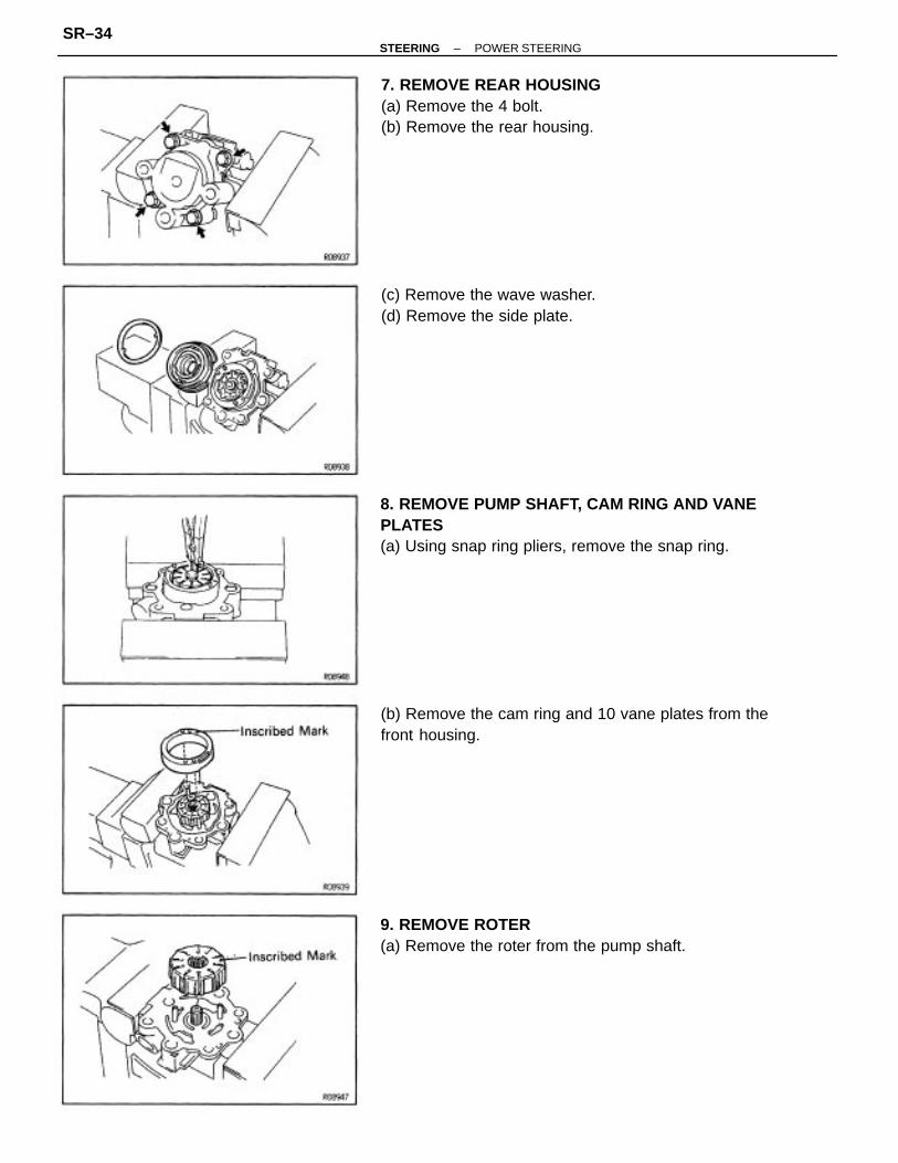
8. REMOVE PUMP SHAFT, CAM RING AND VANEPLATES(a) Using snap ring pliers, remove the snap ring.
(b) Remove the cam ring and 10 vane plates from thefront housing.
7. REMOVE REAR HOUSING(a) Remove the 4 bolt.(b) Remove the rear housing.
9. REMOVE ROTER(a) Remove the roter from the pump shaft.
(c) Remove the wave washer.(d) Remove the side plate.
–STEERING POWER STEERINGSR–34
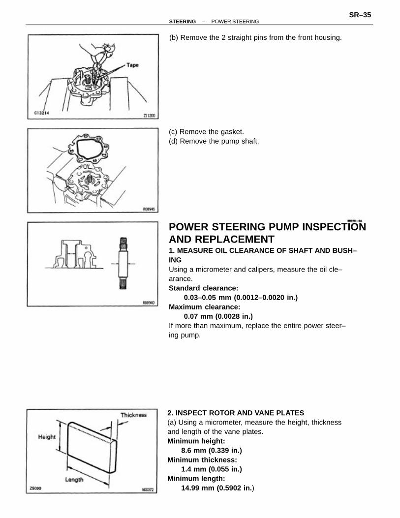
POWER STEERING PUMP INSPECTIONAND REPLACEMENT1. MEASURE OIL CLEARANCE OF SHAFT AND BUSH–INGUsing a micrometer and calipers, measure the oil cle–arance.Standard clearance:
0.03–0.05 mm (0.0012–0.0020 in.)Maximum clearance:
0.07 mm (0.0028 in.)If more than maximum, replace the entire power steer–ing pump.
2. INSPECT ROTOR AND VANE PLATES(a) Using a micrometer, measure the height, thicknessand length of the vane plates.Minimum height:
8.6 mm (0.339 in.)Minimum thickness:
1.4 mm (0.055 in.)Minimum length:
14.99 mm (0.5902 in. )
(b) Remove the 2 straight pins from the front housing.
(c) Remove the gasket.(d) Remove the pump shaft.
–STEERING POWER STEERINGSR–35

(b) Using a feeler gauge, measure the clearance betweenthe rotor groove and vane plate.Maximum clearance:
0.03 mm (0.0012 in.)If more than maximum, replace the vane plate and/orrotor with one having the same mark stamped on thecam ring.Inscribed mark:
1, 2, 3, 4 or NoneHINT: There are 5 vane lengths with the followingrotor and cam ring marks:
(b) Check the flow control valve for leakage.Close one of the holes and apply compressed air [392–490 kPa (4–5 kgf/cm2, 57–71 psi)] into the oppo–site side, and confirm that air does not come out fromthe end holes.
3. INSPECT FLOW CONTROL VALVE(a) Coat the valve with power steering fluid and checkthat it falls smoothly into the valve hole by its ownweight.
If necessary, replace the valve with one having thesame letter as inscribed on the front housing.Inscribed mark:
A, B, C, D, E or F
14.995–14.997 (0.59035–0.59043)
14.993–14.995 (0.59027–0.59035)
14.911 –14.993 (0.59020–0.59027)
14.997–14.999 (0.59043–0.59051)
14.999 –15.001 (0.59051 –0.59059)
Rotor and camring mark Vane length mm (in.)
None
–STEERING POWER STEERINGSR–36
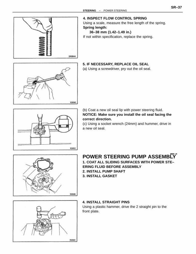
POWER STEERING PUMP ASSEMBLY1. COAT ALL SLIDING SURFACES WITH POWER STE–ERING FLUID BEFORE ASSEMBLY2. INSTALL PUMP SHAFT3. INSTALL GASKET
(b) Coat a new oil seal lip with power steering fluid.NOTICE: Make sure you install the oil seal facing thecorrect direction.(c) Using a socket wrench (24mm) and hummer, drive ina new oil seal.
4. INSPECT FLOW CONTROL SPRINGUsing a scale, measure the free length of the spring.Spring length:
36–38 mm (1.42–1.49 in.)If not within specification, replace the spring.
4. INSTALL STRAIGHT PINSUsing a plastic hammer, drive the 2 straight pin to thefront plate.
5. IF NECESSARY, REPLACE OIL SEAL(a) Using a screwdriver, pry out the oil seal.
–STEERING POWER STEERINGSR–37

6. INSTALL SIDE PLATE AND WAVE WASHER(a) Align the holes of the side plate with the pins, andinstall the plate.(b) Install the wave washer.
5. INSTALL CAM RING, ROTOR AND VANE PLATES(a) Install the roter to the shaft with the inscribed markfacing outward.
(b) Align the holes of the cam ring and straight pins, andinstall the cam ring with the inscribed mark facingoutward.
(d) Coat the vane plates with power steering fluid.(e) Install the 10 vane plates with the round end facingoutward.
(c) Using snap ring pliers, install the snap ring.
–STEERING POWER STEERINGSR–38

10. INSTALL FLOW CONTROL VALVE(a) Install the spring and flow control valve into the hous–ing.(b) Coat a new O–ring with power steering fluid, andinstall it to the pressure port union.(c) Install and torque the pressure port union.Torque: 83 N–m (850 kgf–cm, 62 ft–lbf)
8. MEASURE PUMP SHAFT PRELOAD(a) Check that the shaft rotates smoothly without abnor–mal noise.(b) Temporarily install the pulley nut and check the rotat–ing torque.Rotating torque: 0.3 N–m (2.8 kgf–cm, 2.4 in.–lbf) or less
11. INSTALL AIR CONTROL VALVE(a) Install a new gasket.(b) Install the air control valve.Torque: 69 N–m (700 kgf–cm. 51 ft–lbf)
9. INSTALL PUMP BRACKETInstall the pump bracket with the 3 bolts.Torque: 17 N–m (170 kgf–cm, 12 ft–lbf)
7. INSTALL REAR HOUSINGInstall and torque the 4 bolts.Torque: 43 N–m (440 kgf–cm, 22 ft–lbf)
–STEERING POWER STEERINGSR–39

12. INSTALL SUCTION PORT UNION(a) Coat a new O–ring with power steering fluid, andinstall it to the suction port union.(b) Install the suction port union.(c) Install and torque the bolt.Torque: 13 N–m (130 kgf–cm, 9 ft–lbf)
13. INSTALL PS PUMP PULLEY(a) Install the pump pulley to the shaft.(b) Using SST, install and torque the pulley set nut.SST 09960–10010 (09963–01000)Torque: 43 N–m (440 kgf–cm, 32 ft–lbf)
–STEERING POWER STEERINGSR–40

POWER STEERING PUMP(1MZ–FE)POWER STEERING PUMP REMOVAL ANDINSTALLATIONRemove and install the parts, as shown.
–STEERING POWER STEERINGSR–41

MAIN POINTS OF REMOVAL ANDINSTALLATION1. REMOVE PRESSURE TUBESUsing SST, remove the pressure tubes.SST 09631–220202. ADJUST DRIVE BELT TENSION AFTER INSTALL–ING PS PUMP3. BLEED POWER STEERING SYSTEM
–STEERING POWER STEERINGSR–42
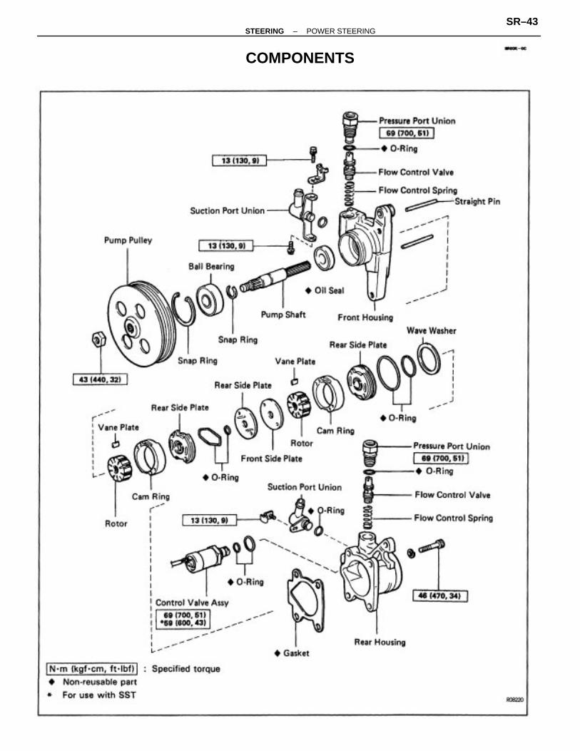
COMPONENTS
–STEERING POWER STEERINGSR–43

POWER STEERING PUMP DISASSEMBLY1. MOUNT POWER STEERING PUMP IN VISENOTICE: Do not tighten the vise to tight.2. REMOVE PS PUMP PULLEY(a) Using SST, remove the pulley set nut.SST 09960–10010 (09963–01000)(b) Remove the pump pulley from the shaft.
5. REMOVE FLOW CONTROL VALVEFor PS:(a) Remove the pressure port union.(b) Remove the 0–ring from the pressure port union.
4. REMOVE SUCTION PORT UNIONS(a) Remove the 3 bolts and 2 suction port unions.(b) Remove the O–ring from each suction port union.
(b) Remove the O–ring from the control valve.(c) Remove the O–ring from the rear housing.
3. REMOVE CONTROL VALVE(a) Using SST, remove the control valve.SST 09612–24014 (09617–24030)
–STEERING POWER STEERINGSR–44

8. REMOVE CAM RING, ROTOR AND VANE PLATEFor Hydraulic Cooling Fan System:Remove the cam ring, rotor and 10 vane plates.NOTICE: Be careful not to confuse the cam ring, rotorand vane plates of the hydraulic cooling fan system withthose of the PS.
6. REMOVE FLOW CONTROL VALVEFor Hydraulic Cooling Fan System:(a) Remove the pressure port union.(b) Remove the O–ring from the pressure port union.
(c) Using a magnetic finger, remove the flow controlvalve and spring.NOTICE: Be careful not to confute the flow control valveof the PS with that of the hydraulic cooling fan system.
(c) Using a magnetic finger, remove the flow controlvalve and spring.NOTICE: Be careful not to confuse the flow control valveof the hydraulic cooling fan system with that of the PS.
7. REMOVE REAR HOUSINGUsing a hexagon wrench (8 mm), remove the 4 bolts,rear housing and gasket.
–STEERING POWER STEERINGSR–45

10. REMOVE CAM RING, ROTOR AND VANE PLATESFor PS:Remove the cam ring, rotor and 10 vane plates.NOTICE: Be careful not to confuse the cam ring, rotorand vane plates of the PS with those of the hydrauliccooling fan system.
9. REMOVE FRONT SIDE PLATE AND 2 REAR SIDEPLATES(a) Remove the front side plate and 2 rear side plates.(b) Remove the 2 0–rings from the rear side plate.
11. REMOVE STRAIGHT PINSPut each straight pin in the vise and rotate the hous–ing to pull the straight pin out from the housing.
12. REMOVE PUMP SHAFT(a) Using snap ring pliers, remove the snap ring.
(b) Using a plastic hammer, tap out the pump shaft.
–STEERING POWER STEERINGSR–46

POWER STEERING PUMP INSPECTIONAND REPLACEMENTNOTICE: Be careful not to confuse the parts of the PSwith those of the hydraulic cooling fan system.1. MEASURE OIL CLEARANCE OF SHAFT AND BUSH–INGUsing a micrometer and calipers, measure the oil cle–arance.Standard clearance:
0.03–0.05 mm (0.0012–0.0020 in.)Maximum clearance:
0.07 mm (0.0028 in.)If more than maximum, replace the entire power steer–ing pump.2. INSPECT ROTOR AND VANE PLATES(a) Using a micrometer, measure the height, thicknessand length of the vane plates.For PSMinimum height:
8.6 mm (0.339 in.)Minimum thickness:
1.4 mm (0.055 in.)Minimum length:
14.99 mm (0.5902 in.)
13. REMOVE REAR SIDE PLATE AND WAVE WASHERFROM REAR HOUSING(a) Install a suitable bolt and plate washer to the rearplate.(b) Using SST, remove the rear plate.SST 09910 – 00015 (09911– 00011, 09912 – 00010)
(c) Remove the 2 0– rings from the rear side plate.(d) Remove the wave washer.
–STEERING POWER STEERINGSR–47

(b) Using a feeler gauge, measure the clearance betweenthe rotor groove and vane plate.Maximum clearance:
0.035 mm (0.0014 in.)If more than maximum, replace the vane plate and/orrotor.HINT: There are 5 lengths with the following rotor andcam ring marks.Power Steering Vane Lengths
For Hydraulic Cooling Fan SystemMinimum height:
8.1 mm (0.319 in.)Minimum thickness:
1.8 mm (0.071 in.)Minimum length:
14.98 mm (0.5898 in.)
Hydraulic Cooling Fan System Vane Lengths
Vane length mm (in.)
Vane length mm (in.)
Cam ring mark
Cam ring mark Rotor mark
Rotor mark
–STEERING POWER STEERINGSR–48

(b) Check the flow control valve for leakage.Close one of the holes and apply compressed air [392–490 kPa (4–5 kgf/cm2, 57–71 psi)] into the oppo–site side, and confirm that air does not come out fromthe end holes.
3. INSPECT FLOW CONTROL VALVE(a) Coat the valve with power steering fluid and checkthat it falls smoothly into the valve hole by its ownweight.
4. INSPECT FLOW CONTROL SPRINGUsing a scale, measure the free length of the spring.Spring length:
37–39 mm (1.46–1.54 in.)
If necessary, replace the valve with one having thesame letter as inscribed on the front housing.Inscribed mark:
A, B, C, D, E or F
5. IF NECESSARY, REPLACE OIL SEAL(a) Using SST and a hammer, drive out the oil seal.SST 09631–10030
–STEERING POWER STEERINGSR–49
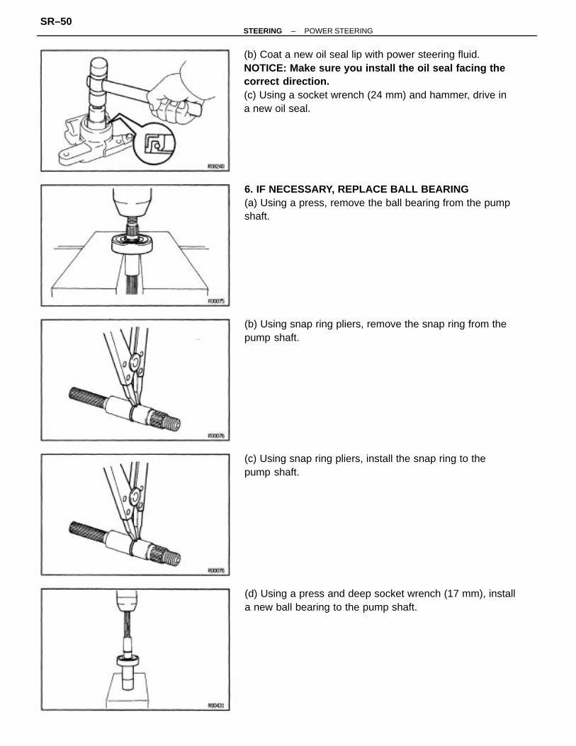
(b) Coat a new oil seal lip with power steering fluid.NOTICE: Make sure you install the oil seal facing thecorrect direction.(c) Using a socket wrench (24 mm) and hammer, drive ina new oil seal.
6. IF NECESSARY, REPLACE BALL BEARING(a) Using a press, remove the ball bearing from the pumpshaft.
(d) Using a press and deep socket wrench (17 mm), installa new ball bearing to the pump shaft.
(b) Using snap ring pliers, remove the snap ring from thepump shaft.
(c) Using snap ring pliers, install the snap ring to thepump shaft.
–STEERING POWER STEERINGSR–50

4. INSTALL CAM RING, ROTOR AND VANE PLATESFor PS:(a) Align the holes of the cam ring and straight pins, andinstall the cam ring with the inscribed mark facingoutward.(b) Install the rotor to the shaft with the inscribed markfacing outward.(c) Coat the vane plates with power steering fluid.(d) Install the 10 vane plates with the round end facingoutward.5. INSTALL FRONT SIDE PLATE AND 2 REAR SIDEPLATES(a) Install 2 new 0–rings to the rear side plate.(b) Align the holes of the plates and straight pins, andinstall the plates.
POWER STEERING PUMP ASSEMBLY1. COAT ALL SLIDING SURFACES WITH POWER STE–ERING FLUID BEFORE ASSEMBLY2. INSTALL PUMP SHAFT(a) Using SST and a press, install the pump shaft with theball bearing.SST 09238–47012
3. INSTALL STRAIGHT PINSUsing a plastic hammer, tap in the 2 straight pins.
(b) Using snap ring pliers, install the snap ring.
–STEERING POWER STEERINGSR–51

6. INSTALL CAM RING, ROTOR AND VANE PLATESFor Hydraulic Cooling Fan System:(a) Align the holes of the cam ring and straight pins, andinstall the cam ring with the inscribed mark facingoutward.(b) Install the rotor to the shaft with the inscribed markfacing outward.(c) Coat the vane plates with power steering fluid.(d) Install the 10 vane plates with the round end facingoutward.7. INSTALL REAR SIDE PLATE AND WAVE WASHER(a) Install 2 new 0–rings to the rear side plate.(b) Align the holes of the side plate with the pins, andinstall the plate.(c) Install the wave washer.
9. MEASURE PUMP SHAFT PRELOAD(a) Check that the shaft rotates smoothly with out abnor–mal noise.(b) Temporarily install the pulley nut and check the rotat–ing torque.Rotating torque:
0.3 N–m (2.8 kgf–cm, 2.4 in.–lbf) or less
8. INSTALL REAR HOUSING(a) Install a new gasket and the rear housing.HINT: Be careful when aligning the gasket.(b) Using a hexagon wrench (8 mm), install and torque the4 bolts.Torque: 46 N–m (470 kgf–cm, 34 ft–lbf)
10. INSTALL FLOW CONTROL VALVEFor Hydraulic Cooling Fan System:(a) Install the spring and flow control valve into the hous–ing.
–STEERING POWER STEERINGSR–52

12. INSTALL SUCTION PORT UNIONS(a) Coat 2 new 0–rings with power steering fluid, andinstall them to each suction port union.(b) Install the suction port union with the 3 bolts.Torque: 13 N–m (130 kgf–cm, 9 ft–lbf)
11. INSTALL FLOW CONTROL VALVEFor PS:(a) Install the spring and flow control valve into the hous–ing.
13. INSTALL CONTROL VALVE(a) Coat a new O–ring with power steering fluid, andinstall it to the rear housing.(b) Install a new O–ring to the control valve.
(b) Coat a new O–ring with power steering fluid, andinstall it to the pressure port union.(c) Install and torque the pressure port union.Torque: 69 N–m (700 kgf–cm, 61 ft–lbf)
(b) Coat a new O–ring with power steering fluid, andinstall it to the pressure port union.(c) Install and torque the pressure port union.Torque: 69 N–m (700 kgf–cm, 51 ft–Ibf)
–STEERING POWER STEERINGSR–53

(c) Using SST, install and torque the control valve.SST 09612–24014 (09617–24030)Torque: 59 N–m (600 kgf–cm, 43 ft–lbf)HINT: Use a torque wrench with a fulcrum length of340 mm (13.39 in.).
14. INSTALL PS PUMP PULLEY(a) Install the pump pulley to the shaft.(b) Using SST, install and torque the pulley set nut.SST 09960–10010 (09963–01000)Torque: 43 N–m (440 kgf–cm, 32 ft–lbf)
–STEERING POWER STEERINGSR–54

MAIN POINTS OF REMOVAL ANDINSTALLATIONNOTICE: When disconnecting the sliding yoke during re–moval of the gear housing, remove the steering wheeland perform centering of the spiral cable.(See page RS–20)If the operation is performed without removing the steer–ing wheel, use the procedure below to make sure thesteering wheel is firmly fixed in position and cannot turn.
GEAR HOUSINGSTEERING GEAR HOUSING REMOVALAND INSTALLATIONRemove and install the parts, as shown.
–STEERING POWER STEERINGSR–55

(c) Place matchmarks on the sliding yoke and controlvalve shaft.(d) Loosen the bolt on the upper side of the sliding yoke,remove the bolt on the lower side and disconnect thesliding yoke.
3. DISCONNECT PRESSURE AND RETURN TUBESUsing SST, disconnect and connect the pressure andreturn tubes.SST 09631 –22020Torque: 25 N–m (250 kgf–cm, 18 ft.–lbf)
2. DISCONNECT TIE ROD ENDS(a) Remove the cotter pins and nuts.(b) Using SST, disconnect the tie rod end from the knuck–le arm.SST 09628–62011
1. DISCONNECT SLIDING YOKE(a) Position the front wheels facing straight ahead.(b) Using the seat belt of the driver’s seat, fix the steeringwheel so that it does not turn.
4. REMOVE STABILIZER BAR SET BOLTSRemove the 4 stabilizer bar set bolts.
–STEERING POWER STEERINGSR–56

(b) Align matchmarks on the sliding yoke and controlvalve shaft and connect them.7. CENTER SPIRAL CABLEIf the steering wheel has been removed, or the steer–ing wheel may have moved during the operation,always perform centering of the spiral cablle.(See page RS–20)8. CHECK STEERING WHEEL CENTER POINT9. CHECK TOE–IN
(b) Slide the gear housing to the RH side.NOTICE: Do not damage the turn pressure tube.6. CONNECT SLIDING YOKE(a) Set the gear housing so that it matches the dimen–sions shown below, with the gear housing at thecenter point.
5. REMOVE GEAR HOUSING(a) Remove the 2 set bolts.
–STEERING POWER STEERINGSR–57

COMPONENTS
–STEERING POWER STEERINGSR–58
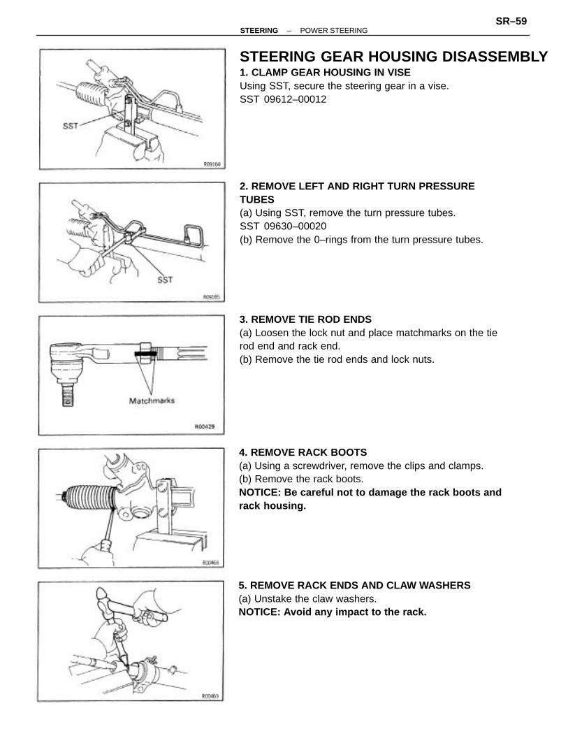
STEERING GEAR HOUSING DISASSEMBLY1. CLAMP GEAR HOUSING IN VISEUsing SST, secure the steering gear in a vise.SST 09612–00012
2. REMOVE LEFT AND RIGHT TURN PRESSURETUBES(a) Using SST, remove the turn pressure tubes.SST 09630–00020(b) Remove the 0–rings from the turn pressure tubes.
4. REMOVE RACK BOOTS(a) Using a screwdriver, remove the clips and clamps.(b) Remove the rack boots.NOTICE: Be careful not to damage the rack boots andrack housing.
3. REMOVE TIE ROD ENDS(a) Loosen the lock nut and place matchmarks on the tierod end and rack end.(b) Remove the tie rod ends and lock nuts.
5. REMOVE RACK ENDS AND CLAW WASHERS(a) Unstake the claw washers.NOTICE: Avoid any impact to the rack.
–STEERING POWER STEERINGSR–59

(b) Using SST, remove the rack ends.SST 09617–14010(e) Mark the left and right rack ends accordingly.(d) Remove the claw washers.
6. REMOVE RACK GUIDE SPRING CAP LOCK NUTUsing SST, remove the rack guide spring cap lock nut.SST 09612 – 24014 (09617 – 24020)
7. REMOVE RACK GUIDE SPRING CAPUsing SST, remove the rack guide spring cap.SST 09631 –10021
8. REMOVE RACK GUIDE SPRING, RACK GUIDE ANDSEAT
9. REMOVE RACK HOUSING GAP
–STEERING POWER STEERINGSR–60

11. REMOVE CONTROL VALVE HOUSING(a) Remove the dust cover.(b) Place matchmarks on the valve housing and rackhousing.(c) Remove the 2 bolts.(d) Pull out the valve with the valve housing.(e) Remove the gasket from the rack housing.
(b) Using a screwdriver, pry a part the clasp of the No.2bracket.(c) Remove the bushing and bracket from the rack hous–ing.(d) Remove the bushing from the bracket.
10. REMOVE SELF– LOCKING NUTUsing SST to hold the control valve, remove the self–locking nut.SST 09616 – 00010
13. REMOVE N0.2 BRACKET(a) Place matchmarks on the bracket and rack housing.
12. REMOVE CONTROL VALVE FROM HOUSINGTap out the control valve and oil seal.
–STEERING POWER STEERINGSR–61

W” –01
STEERING GEAR HOUSING INSPECTIONAND REPLACEMENT1. INSPECT RACK(a) Using a dial indicator, check the rack for runout andfor tooth wear or damage.Maximum runout:
0.3 mm (0.012 in.)(b) Check the back surface for wear or damage.If faulty, replace it.2. IF NECESSARY, REPLACE CONTROL VALVE HOUS–ING OIL SEAL AND UPPER BEARING(a) Using SST, press out the oil seal and upper bearing.SST 09620–30010 (09631 –00020)09630–24013 (09620–24020)
14. REMOVE CYLINDER END STOPPER(a) Using SST, turn the cylinder end stopper clockwiseuntil the wire end comes out.SST 09631 –16010(b) Using SST, turn the cylinder end stopper counter–clockwise, and remove the wire.SST 09631 –16010
15. REMOVE RACK BUSHING AND RACK(a) Using a brass bar, tap out the rack with the rackbusing.(b) Remove the 0–ring from the bushing.
16. REMOVE CYLINDER SIDE OIL SEAL AND SPACERUsing SST and a brass bar, drive out the oil seal andspacer.SST 09620–30010 (09623–30010)
–STEERING POWER STEERINGSR–62

(d) Using SST, press in a new upper bearing, as shown.SST 09620–30010 (09631–00020)09630–24013 (09620–24020)NOTICE: Press in the bearing so that the inscribed markon the bearing can be seen.
(c) Coat a new center bearing with grease.(d) Using SST, press in a new center bearing, as shown.SST 09630–24013 (09620–24020),09631–12020
(b) Coat a new oil seal with power steering fluid.(c) Using SST, press in a new oil seal, as shown.SST 09620–30010 (09631–00020)09630–24013 (09620–24020)
3. IF NECESSARY, REPLACE CONTROL VALVELOWER BEARING AND CENTER BEARING(a) Using a brass bar, drive out the lower bearing.
(b) Using SST, remove the center bearing.SST 09612 – 24014 (09613 – 22011)
–STEERING POWER STEERINGSR–63

5. IF NECESSARY, REPLACE STEERING RACKTEFLON RING AND O–RING(a) Using a screwdriver, remove the teflon ring and 0–ring.NOTICE: Be careful not to damage the groove for theteflon ring.(b) Coat a new O–ring with power steering fluid andinstall it.
4. IF NECESSARY, REPLACE RACK BUSHING OILSEAL(a) Using SST, remove the oil seal.SST 09612 – 24014 (09613 – 22011)
(b) Coat a new oil seal with power steering fluid.(c) Using SST, press in the oil seal.SST 09631–32010
(e) Using SST, press in a new lower bearing.SST 09630–24013 (09620–24020),09631 –12020
(c) Expand a new teflon ring with your fingers.NOTICE: Be careful not to over–expand the teflon ring.
–STEERING POWER STEERINGSR–64

6. IF NECESSARY, REPLACE CONTROL VALVETEFLON RINGS(a) Using a screwdriver, remove the 4 teflon rings.NOTICE: Be careful not to damage the grooves for theteflon ring.
(e) Carefully slide the tapered end of the SST over theteflon rings to seat the rings.SST 09631– 20081NOTICE: Be careful not to damage the teflon rings.
(d) Install the teflon ring to the rack.(e) Install the expanded teflon ring to the steering rackand snug it down with your fingers.
(c) Install the 4 teflon rings to the control valve.(d) Coat the 4 teflon rings with power steering fluid andsnug them down with your fingers.
(b) Expand 4 new teflon rings with your fingers.NOTICE: Be careful not to over–expand the teflon ring.
–STEERING POWER STEERINGSR–65

(b) Install new 0–rings to the control valve.(c) Install the expanded new teflon rings to the controlvalve.(d) Carefully position the teflon rings into the controlvalve grooves.NOTICE: Be careful not over–expand the teflon rings.(e) Coat the teflon rings with power steering fluid, andsnug them down with your fingers.NOTICE: Be careful not to damage the teflon rings.
STEERNG GEAR HOUSING ASSEMBLY”1. INSTALL CYLINDER HOUSING OIL SEAL ANDSPACER(a) Coat a new oil seal lip with power steering fluid.(b) Tape the showing part of SST before use.(c) Install the oil seal to SST, and press in it.SST 09608–12010 (09608–00080),09631 –12020
2. INSTALL RACK(a) Install SST to the rack.HINT: If necessary, scrape the burrs off the rack teethend and burnish.SST 09631 –33010
7. IF NECESSARY, REPLACE HYDRAULIC REACTIONCHAMBER TEFLON RINGS AND O–RINGS(a) Remove the teflon rings and 0–rings.NOTICE: Be careful not to damage the control valve.
(b) Coat SST with power steering fluid.(e) Insert the rack into the cylinder.(d) Remove SST.
–STEERING POWER STEERINGSR–66

3. INSTALL RACK BUSHING AND CYLINDER ENDSTOPPER(a) To prevent oil seal lip damage, wind vinyl tape on thesteering rack end, and apply power steering fluid.(b) Coat a new O–ring with power steering fluid andinstall it to the bushing.(c) Push in the rack bushing and cylinder end stopperuntil the wire installation hole appears.
5. AIR TIGHTNESS TEST(a) Install SST to the unions of the cylinder housing.SST 09631–12071(b) Apply 53.3 kPa (400 mmHg, 15.75 in.Hg) of vacuumfor about 30 seconds.(c) Check that there is no change in the vacuum.If there is change in the vacuum, check the installationof the rack housing oil seal.
4. INSTALL WIRE(a) Insert a new wire end into the hole.(b) Using SST, turn the cylinder end stopper clockwiseuntil the wire end disappears.SST 09631–16010NOTICE: Take care to avoid tightening the rack morethan needed.
(c) Install the bushing and bracket to the rack housing.HINT: Align the matchmarks on the bracket and rackhousing.
6. INSTALL NO.2 BRACKET(a) Coat the grommets inner edge with the grease.(b) Install the bushing to the bracket.
–STEERING POWER STEERINGSR–67
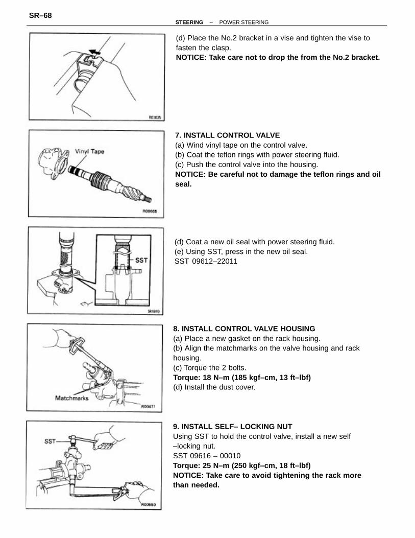
8. INSTALL CONTROL VALVE HOUSING(a) Place a new gasket on the rack housing.(b) Align the matchmarks on the valve housing and rackhousing.(c) Torque the 2 bolts.Torque: 18 N–m (185 kgf–cm, 13 ft–lbf)(d) Install the dust cover.
9. INSTALL SELF– LOCKING NUTUsing SST to hold the control valve, install a new self–locking nut.SST 09616 – 00010Torque: 25 N–m (250 kgf–cm, 18 ft–lbf)NOTICE: Take care to avoid tightening the rack morethan needed.
7. INSTALL CONTROL VALVE(a) Wind vinyl tape on the control valve.(b) Coat the teflon rings with power steering fluid.(c) Push the control valve into the housing.NOTICE: Be careful not to damage the teflon rings and oilseal.
(d) Place the No.2 bracket in a vise and tighten the vise tofasten the clasp.NOTICE: Take care not to drop the from the No.2 bracket.
(d) Coat a new oil seal with power steering fluid.(e) Using SST, press in the new oil seal.SST 09612–22011
–STEERING POWER STEERINGSR–68

12. ADJUST TOTAL PRELOAD(a) Apply sealant to 2 or 3 threads of the spring cap.Sealant:
Part No.08833–00080, THREE BOND 1344, LOC–TITE 242 or equivalent
(b) Using SST, install and torque the spring cap.SST 09631 –10021Torque: 25 N–m (250 kgf–cm, 18 ft–Ibf)
10. INSTALL RACK HOUSING CAP(a) Apply sealant to 2 or 3 threads of the housing cap.Sealant:
Part No.08833 – 00080, THREE BOND 1344, LOC–TITE 242 or equivalent
(b) Install the rack housing cap.Torque: 59 N–m (600 kgf–cm, 43 ft–Ibf)
(c) Using SST, return the rack guide spring cap 12�.SST 09631–10021(d) Turn the control valve shaft right and left 1 or 2 times.(e) Loosen the spring cap until the rack guide compres–sion spring is not functioning.
11. INSTALL RACK GUIDE SEAT, RACK GUIDE ANDSPRING(a) Coat the fitting surfaces between the rack guide seatand the rack guide with grease.(b) Install the rack guide seat, rack guide and spring.
(c) Using a center punch, stake the housing at 2 places.
–STEERING POWER STEERINGSR–69
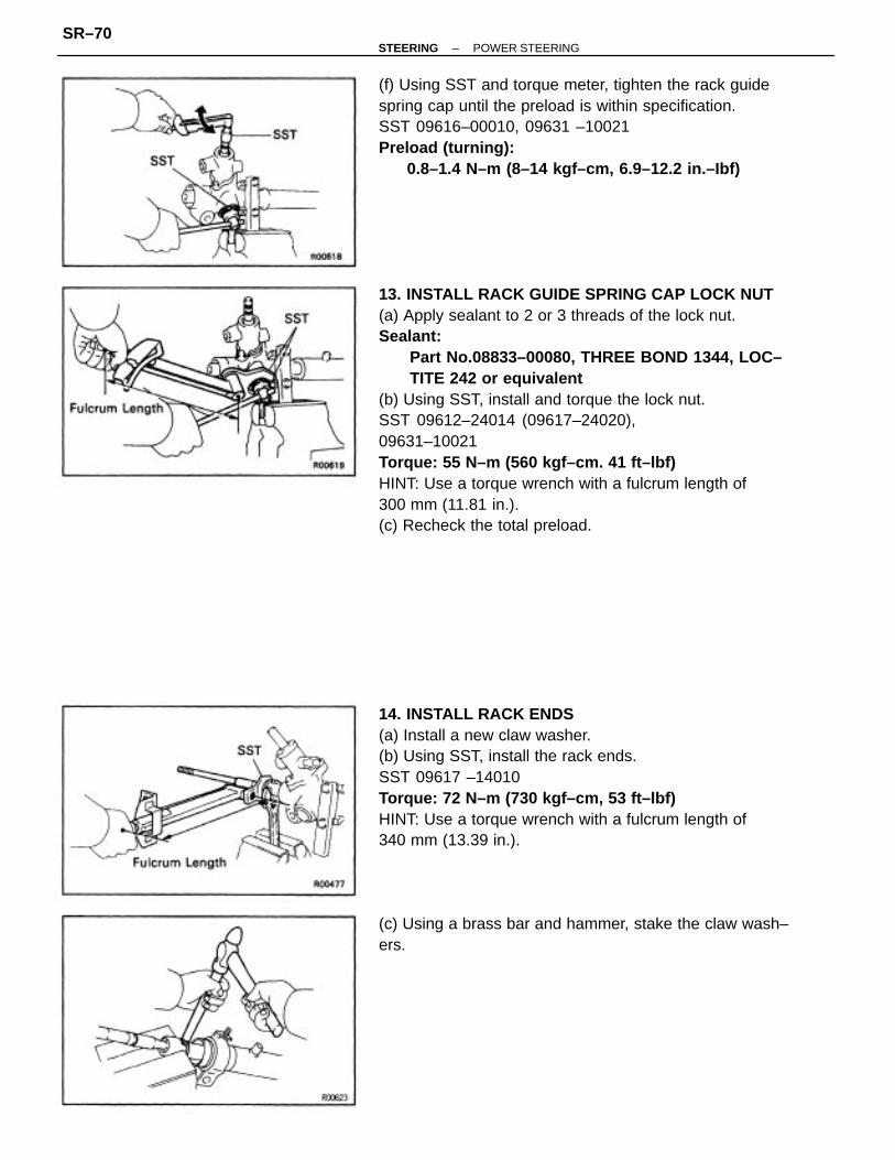
13. INSTALL RACK GUIDE SPRING CAP LOCK NUT(a) Apply sealant to 2 or 3 threads of the lock nut.Sealant:
Part No.08833–00080, THREE BOND 1344, LOC–TITE 242 or equivalent
(b) Using SST, install and torque the lock nut.SST 09612–24014 (09617–24020),09631–10021Torque: 55 N–m (560 kgf–cm. 41 ft–lbf)HINT: Use a torque wrench with a fulcrum length of300 mm (11.81 in.).(c) Recheck the total preload.
14. INSTALL RACK ENDS(a) Install a new claw washer.(b) Using SST, install the rack ends.SST 09617 –14010Torque: 72 N–m (730 kgf–cm, 53 ft–lbf)HINT: Use a torque wrench with a fulcrum length of340 mm (13.39 in.).
(f) Using SST and torque meter, tighten the rack guidespring cap until the preload is within specification.SST 09616–00010, 09631 –10021Preload (turning):
0.8–1.4 N–m (8–14 kgf–cm, 6.9–12.2 in.–Ibf)
(c) Using a brass bar and hammer, stake the claw wash–ers.
–STEERING POWER STEERINGSR–70

17. INSTALL RIGHT AND LEFT TURN PRESSURETUBES(a) Install new O–rings to the tube.(b) Using SST, install and torque the tubes.SST 09633–00020Torque: 11 N–m (110 kgf–cm, 8 ft–lbf)HINT: Use a torque wrench with a fulcrum length of300 mm (11.81 in.).
15. INSTALL RACK BOOTS(a) Ensure that the tube hole is not clogged with grease.HINT: If the tube hole is clogged, the pressure insidethe boot will change after it is assembled and thesteering wheel turned.(b) Install the boots.HINT: Be careful not to damage or twist the boot.
16. INSTALL TIE ROD ENDS(a) Screw the lock nuts and tie rod ends onto the rackends until the matchmarks are aligned.(b) After adjusting toe–in, torque the lock nut.Torque: 74 N–m (750 kgf–cm, 54 ft–lbf)
(c) install the clamps and clips.
–STEERING POWER STEERINGSR–71

SERVICE SPECIFICATIONSSERVICE DATA
Vane plate thickness (Minimum) 1 MZ–FE for Hydraulic cooling fan
Oil pressure at idle speed with valve closed (Minimum) 1 MZ–FE
Vane plate length (Minimum) 1 MZ–FE for Hydraulic cooling fan
Vane plate height (Minimum) 1 MZ–FE for Hydraulic cooling fan
Oil pressure at idle speed with valve closed (Minimum) 5S–FE
Vane plate to rotor groove clearance (Maximum) 1 MZ–FE
Vane plate to rotor groove clearance (Maximum) 5S–FE
Rotor shaft bushing oil clearance (Maximum) 1 MZ–FE
Vane plate length 1 MZ–FE for Hydraulic cooling fan
Rotor shaft bushing oil clearance (Maximum) 5S–FE
Rotor shaft bushing oil clearance (STD) 1 MZ– FE
Vane plate thickness (Minimum) 1 MZ–FE for PS
Rotor shaft bushing oil clearance (STD) 5S–FE
Vane plate length (Minimum) 1 MZ–FE for PS
Vane plate height (Minimum) 1 MZ–FE for PS
Steering effort at idle speed (Maximum)
Vane plate thickness (Minimum) 5S–FE
Drive belt tension 1 MZ–FE (Used belt)
Drive belt tension 1 MZ– FE (New belt)
Drive belt tension 5S–FE (Used belt)
Drive belt tension 5S–FE (New belt)
Vane plate length (Minimum) 5S–FE
Vane plate height (Minimum) 5S–FE
Steering wheel freeplay (Maximum)
Vane plate length 1 MZ–FE for PS
(Cam ring mark) (Rotor mark)
(Cam ring mark) (Rotor mark)
PS ON–VEHICLE INSPECTION
(Cam ring and rotor mark)
Vane plate length 5S–FE
Maximum rise of oil level
PS PUMP
None
–STEERING SERVICE SPECIFICATIONSSR–72

Flow control valve spring length (Minimum) 1 MZ–FE
TORQUE SPECIFICATIONS
Flow control valve spring length (Minimum) 5S–FE
Flow control valve spring length (STD) 5S–FE
Flow control valve spring length (STD) 1 MZ–FE
PS pump installation bolt (Adjusting bolt)
PS pump installation bolt (Through bolt)
Pressure and return tube x Gear housing
POWER STEERING PUMP FOR 1 MZ–FE
POWER STEERING PUMP FOR 5S–FE
Pressure port union x Pump housing
Control valve housing x Rack housing
Pressure port union x Pump housing
Suction port union x Pump housing
Pressure tube x Pressure port union
Suction port union x Pump housing
POWER STEERING GEAR HOUSING
Steering main shaft x Sliding yoke
Pump rotating torque (Maximum)
Control valve shaft x Sliding yoke
Steering rack runout (Maximum)
Control valve self–locking nut
Tie rod end x Steering knuckle
Turn pressure tube union nut
Front housing x Rear housing
Pump puIly x Pump shaft
Pump puIly x Pump shaft
Gear housing x Sub frame
PS pump installation bolt
PS pump x Pressure tube
Total preload (Turning)
Column bracket x Body
Tilt lever x Column tube
STEERING COLUMN
Tie rod end lock nut
PS GEAR HOUSING
Rack housing cap
Control valve assy
Rack x Rack end
Steering wheel
Part tightened
Wheel pad
Lock nut
–STEERING SERVICE SPECIFICATIONSSR–73