Square Rectangle Hex Cone. What are they ? See some examples How do you draw them ?
61
Square Rectangle Hex Cone
-
Upload
kristian-shaw -
Category
Documents
-
view
223 -
download
3
Transcript of Square Rectangle Hex Cone. What are they ? See some examples How do you draw them ?

Square Rectangle Hex Cone

What are they ?See some examples
How do you draw them ?

What are they?They are 3-D shapes which start off with a simple shape such as a Square at the bottom ( THE BASE ) and rise up to a point.
e.g. An Egyptian pyramid starts with a Square base

Some ExamplesTriangle
Circle
Square
Hexagon

How do you draw them ?
We will start with a Square Pyramid

Name : Class : Date : / / Teacher DRAWING
The 2 drawings below both describe the Square prism shown in fig 1.
1. Complete the elevation of each drawing.
2. Complete the end elevation of each drawing

Name : Class : Date : / / Teacher DRAWING
1. Complete the elevation of the drawing.
2. Complete the end elevation of the drawing
3. Produce the surface development

Name : Class : Date : / / Teacher DRAWING
1. Complete the elevation of each drawing.
2. Complete the end elevation of each drawing
3. Produce the development

1 2
34
1/4 2/3

1 2
34
1/4 /32 3/4 /21

Name : Class : Date : / / Teacher DRAWING
1 2
34
1/4 /32 3/4 /21

Name : Class : Date : / / Teacher DRAWING

1 2
34
1/4 /32 3/4 /21

1
1 2
34
1/4 /32 3/4 /21

1
2
3
4
1
1 2
34
1/4 /32 3/4 /21

1
2
3
4
1
1 2
34
1/4 /32 3/4 /21
Outline to Finish

Name : Class : Date : / / Teacher DRAWING
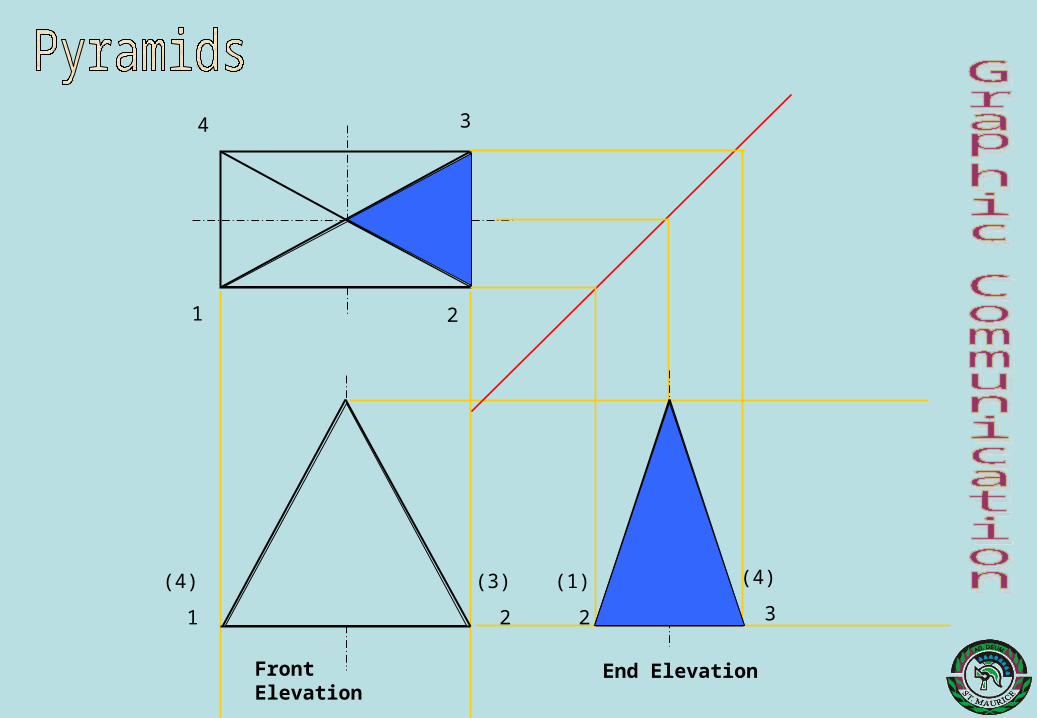
Front Elevation
End Elevation
1
4 3
2
(4)
1
(3)
2
(1)
2
(4)
3

Development of a Rectangular Pyramid
How many sides does it have?
5
Describe the shapes of the sides 4 Triangles and
1 RectangleAre all the triangles the same?
No
Why? Because two edges on the base are long and two are short. This creates two different sizes of triangle.

The Development
Base
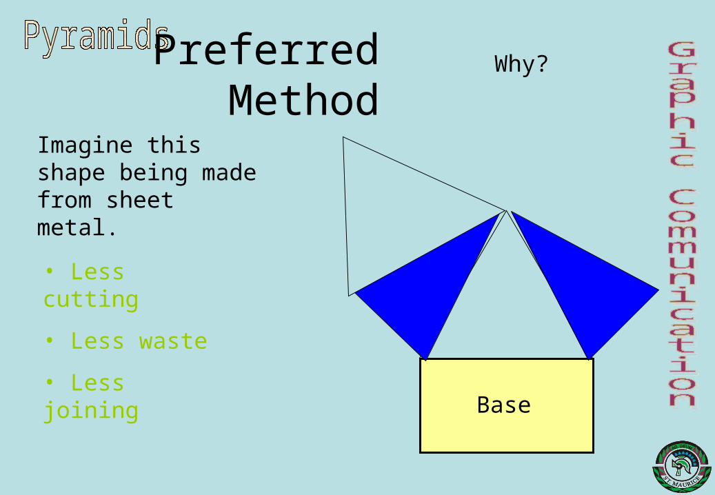
Preferred Method
Base
Why?
• Less cutting
• Less waste
• Less joining
Imagine this shape being made from sheet metal.

Drawing Method
Step 1 - Draw the base
Step 2 requires a True Length which isn’t on the drawing and has to be created

Front Elevation
Because your eye is at right angles to the red line in the plan, the red line in the Front Elevation is a true length
Step 3
Construct the True LengthTr
ue
leng
th

Using the True Length
Step 4
Use the true length to construct the four sides
True length

Name : Class : Date : / / Teacher DRAWING

Solid Hexagonal Pyramid Multi-View

Drawing the Plan View
6
1
2
3
4
5
5/64/13/2

Drawing the End Elevation View
6
1
2
3
4
5
5/64/13/2 4 5/3 6/2 1

Drawing the Surface Development
Use a compass and lift the true length of the pyramid edge.
Draw a horizontal and vertical centre line to indicate the apex of the surface developmentDraw a large Arc with the compass set to the true length.
Use a compass and lift the length of side from the plan
Transfer this size to successive points on the arc. At each mark draw a line across.
Now draw, using a 30o/600
set square, one hexagon in the positions shown.
Draw a line between the apex and the arc. This is the first edge
Draw a straight line between the arc points.

Outline to Finish
6
1
2
3
4
5
5/64/13/2 4 5/3 6/2 1

Name : Class : Date : / / Teacher DRAWING

Cut Square Pyramid - QuestionThe given views show the Front
Elevation and unfinished Plan of a cut square pyramid.
Draw the following views :-
The completed PlanEnd ElevationSurface Development of sidesTrue Shape of cut
Department of Technological EducationDepartment of Technological Education

Finding Position of End ElevationUsing the Plan and the Front
Elevation project the position of the End Elevation and show the slope of the sides.
Department of Technological EducationDepartment of Technological Education
Number each of the points in each view.
1 2
34
1/4 /32 3/4 /21

Finding Position of cut on End ElevationProject from the Front Elevation
to find the cut surface on the End Elevation.
Department of Technological EducationDepartment of Technological Education
Darken the outlines on the End Elevation.
1 2
34
1/4 2 3 /21/3 /4
Department of Technological EducationDepartment of Technological Education

Finding Position of cut on PlanProject from the Front Elevation
to find the cut surface on the Plan.
Darken the outlines on the Plan.
1 2
34
1/4 2/3 3 /21/4
Department of Technological EducationDepartment of Technological Education

Finding True Length of pyramid cornerBefore the Development can be
drawn it is necessary to find out the True Length of the corner of the pyramid so that accurate sizes for the development and the cut points can be found
Draw a curve on the plan with the centre being located at the centre of the pyramid, the radius being measured at one of the corners, and the end point of the curve being the centre line.
1
4
1/4
Project the point found onto the Elevation baseline and draw a generator to the apex of the pyramid.
Project the cut points from the elevation onto this True Length line.
2
3
2/3 3 /21/4
Department of Technological EducationDepartment of Technological Education

Drawing the outline of the DevelopmentIndicate where the development
is going to be placed, and then draw the first generator to indicate one corner of the pyramid.
Measure the length of the corner of the pyramid using the True Length line and draw a curve on the Development at this size.
Step off the length of each of the sides of the pyramid onto the Development.
Draw generators to each of these points to indicate the fold lines
1/4 2/3
1 2
34
Number each of the points.
1
2
3
4
1
3 /21/4
Department of Technological EducationDepartment of Technological Education

Drawing the cut on the DevelopmentStep off from the True Length
line the distance from the apex of the pyramid to each cut point and transfer these sizes to the correct generators on the Development.
Join each of the points to show the developed shape of the cut. Also add the flat edges to the base of the pyramid on the Development.
Darken the outlines on the Development.
Add the fold lines to complete the view.
1
4
1/4
1
2
3
4
1
2
3
2/3 3 /21/4
Department of Technological EducationDepartment of Technological Education

Drawing the True ShapeTo find the True Shape, project
the cut points away from the Front Elevation at right angles to the cut.
Draw a datum line on the True Shape parallel to the cut line of the Front Elevation and at right angles to the lines just projected. Use the centre line of the plan as a datum line.Measure the vertical distances from the datum to each of the cut points on the plan. Transfer each of these sizes on to the True Shape. Join each of the points found to produce the True Shape. Complete the view by darkening the outlines.
1 2
34
1
2
3
4
1
1/4 2/3 3 /21/4
Department of Technological EducationDepartment of Technological Education

Cut cone
The given views show the Front Elevation and part Plan of a cut cone.
Draw the following views :-
Complete PlanEnd ElevationDevelopmentTrue Shape of cut
Department of Technological EducationDepartment of Technological Education

Finding position of End Elevation
Start drawing the End Elevation by projecting the height and width from the given views.
Department of Technological EducationDepartment of Technological Education

Drawing Generators on Plan
Use 30o and 60o lines to divide the Plan into 12 equal parts. 1
2
3
4
567
8
9
10
1211
Number each of the points on the Plan.
Department of Technological EducationDepartment of Technological Education

Transfer Generators from Plan to Elevation
Project each of the points from the Plan onto the Elevation base.
1 2345678
910 11 12
1
2
3
4
567
8
9
10
1211
Number each of the points on the Elevation making sure that the numbers correspond with those on the Plan.
Department of Technological EducationDepartment of Technological Education

Drawing generator on Elevation
Draw generators from the apex of the cone to each of the points found on the base of the cone.
1 2345678
910 11 12
Department of Technological EducationDepartment of Technological Education

Drawing generators onto End Elevation
1211
10
9
8
76 5
4
3
2
1
9108
117
126
15
24 3
Project the position of the generators onto the End Elevation by projecting the points from the Plan.
6584 3
102
111127 9
Number each of the points on the End Elevation.
Draw generators from the apex to the base.
Department of Technological EducationDepartment of Technological Education
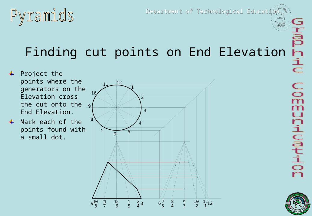
Finding cut points on End Elevation
Project the points where the generators on the Elevation cross the cut onto the End Elevation.
1211
10
9
8
76 5
4
3
2
1
9108
117
126
15
24 3 65
84 3
102
111127 9
Mark each of the points found with a small dot.
Department of Technological EducationDepartment of Technological Education

Completing End Elevation
Complete the End Elevation by drawing a smooth curve through each of the point and then darkening the other outlines on the view.
9108
117
126
15
24 3 65
84 3
102
111127 9
Department of Technological EducationDepartment of Technological Education

Finding cut points on PlanProject the points from the cut on the Elevation up to the correct generator lines on the Plan.
(Note that points 6 and 12 will not be able to be found at this time.)
9108
117
126
15
24 3 65
84 3
102
111127 9
Mark each of the points found with a small dot
Department of Technological EducationDepartment of Technological Education

Finding points 6 and 12 on Plan (alternative 1)
Project point 6 and 12 onto the outside generator on the Elevation.
Project this point up to the centre line of the Plan.
Use compasses to rotate this point onto the correct generators for points 6 and 12.
Mark each of these points with a small dot
Department of Technological EducationDepartment of Technological Education

Finding points 6 and 12 on Plan (alternative 2)
Project points 6 and 12 from the End Elevation onto the correct generators on the Plan.
Department of Technological EducationDepartment of Technological Education

Completing PlanTo complete the Plan draw a smooth curve through each of the 12 points found.
Department of Technological EducationDepartment of Technological Education

Development of surface (1)Mark the position where the apex of the Development will be placed.
Department of Technological EducationDepartment of Technological Education
9 8
76
5
4
3
2
1
12
11
9
10Draw the first generator.
Draw the base line of the Development.
Step off the size to each generator point along the base.
Number each of the points found.
Draw generator lines from the apex to each of the points on the base.
Department of Technological EducationDepartment of Technological Education
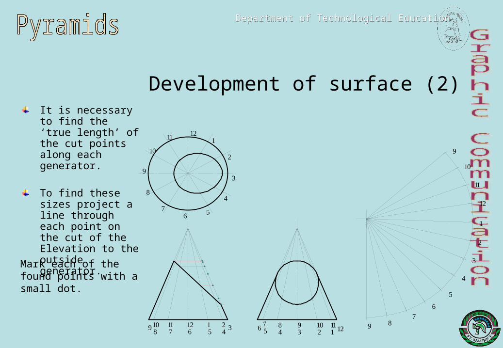
Development of surface (2)
Mark each of the found points with a small dot.
It is necessary to find the ‘true length’ of the cut points along each generator.
To find these sizes project a line through each point on the cut of the Elevation to the outside generator.
Department of Technological EducationDepartment of Technological Education

Development of surface (3)Measure the distance from the apex to each point on the outside generator.
Transfer this size to the correct generator on the Development.
Mark each point with a small dot.
Draw a smooth curve through each point found.
Darken each of the other outlines on the Development.
Department of Technological EducationDepartment of Technological Education

True Shape of cut (1)Project each of the points on the cut of the Elevation away at right angles to the cut surface.
Draw a datum line on the True Shape – in this case the centre line has been chosen.
Number each of the lines projected up to the True Shape.
Department of Technological EducationDepartment of Technological Education

True Shape of cut (2)Measure the sizes from the cut points to the centre line on the Plan and transfer each of these sizes to the correct lines on the True Shape.
Note – These sizes can also be measured from the End Elevation.
Mark each of the points with a small dot.
Department of Technological EducationDepartment of Technological Education

True Shape of cut (3)To finish the True Shape draw a smooth curve through each of the points found.
The final drawing should look like this.
Department of Technological EducationDepartment of Technological Education

Name : Class : Date : / / Teacher DRAWING

SUMMARY

Name : Class : Date : / / Teacher DRAWING

Name : Class : Date : / / Teacher DRAWING