SPV 8000 Service & Installation Manual - Price Industries · The SPV 8000 has been designed to...
12
Transcript of SPV 8000 Service & Installation Manual - Price Industries · The SPV 8000 has been designed to...

� © Copyright E.H. Price Limited 2006
SPV8000
General DescriptionThe SPV 8000 terminal unit controls room temperature by varying the flow of warm or cool air to the room. The terminal unit also compensates for changes in inlet duct pressure, holding the air flow constant unless signaled to change by the thermostat. In other words, the SPV 8000 is pressure independent. Note: Because of this compensating action, if it is necessary to counter a change in duct pressure, then the damper may be seen closing when the thermostat is calling for air flow or opening when the thermostat is satisfied.Both the room thermostat and the air flow sensor send air pressure signals to the pneumatic controller. The controller in turn modulates the pneumatic damper actuator.
Receiving InspectionAfter unpacking the assembly, check it for shipping damage. If any shipping damage is found, report it immediately to the delivering carrier. During unpacking and installation do not handle by the inlet velocity sensor, damper shaft, or tubing connections. Damage may result.
Installing the Price SPV 8000 Terminal UnitThe basic SPV 8000 is light enough that it can be supported by the duct work in which it is installed. Where accessory modules, such as coils, attenuators or multiple outlets are included, the assembly should be supported directly. Use the support method prescribed for the rectangular duct in the job specifications.
Important: For optimum performance there should be a minimum of 3 duct diameters of straight inlet duct, same size as the inlet, between the inlet and any transition, take off or fitting. The assembly must be mounted right side up. It must be level within ±10 degrees of horizontal, both parallel to the air flow and at right angles to the air flow. The control side of the assembly is labelled with an arrow indicating UP.
To prevent excess air leakage, all cleat joints should be sealed with an approved duct sealer. This would apply to all accessory module connections as well as the basic assembly.
Control Air ConnectionsExternal lines are provided for main air and thermostat connections. Pipe according to the label on the inlet panel; main air to blue, thermostat line to white.
The terminal's side panel is factory marked to identify the mounting position for Johnson, Kreuter, Landis & Staefa and Honeywell pneumatic actuators for both Normally Open or Normally Closed operation (see page 4, Figures 1 and 2).
Damper rotation is always clockwise to the open position. An identification mark on the end of the shaft indicates the damper position.
Capped tees are provided in the sensing lines from the Inlet Velocity Sensor. These allow field connection of a differential pressure gauge for accurate air flow measurement.
NOTE: The main air supply must be clean and dry, delivered at 15 to 25 psi.
Main AirConnection (20 psi)
Thermostat Connection
Pneumatic Actuator
SP300 Flow Sensor
Capped teesfor field velocity
pressure measurements
Controller (CP101 Illustrated)
�© Copyright E.H. Price Limited 2006
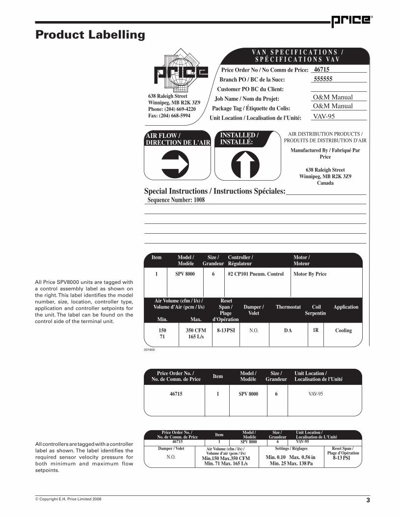
Product Labelling
All Price SPV8000 units are tagged with a control assembly label as shown on the right. This label identifies the model number, size, location, controller type, application and controller setpoints for the unit. The label can be found on the control side of the terminal unit.
All controllers are tagged with a controller label as shown. The label identifies the required sensor velocity pressure for both minimum and maximum flow setpoints.

� © Copyright E.H. Price Limited 2006
Actuator Mounting Instructions
The SPV 8000 has been designed to accommodate several manu-facturers' actuators for both normally open or normally closed fail-safe operation.
Figure 1 illustrates the standard actuator and linkage orientation for normally open units. Figure 2 illustrates the orientation of a normally closed unit.
If relocation of the actuator becomes necessary due to a change in required damper fail-safe position from normally open to normally closed or vice versa, the following procedure should be used:
1. Loosen the crank arm bolt (A) until the damper shaft rotates freely.
2. Remove the screws (B) securing the actuator mounting bracket to the base.
3. Relocate the actuator to the proper mounting holes as per Figure 3 and Table 1.
4. Insure the actuator linkage is in the proper orientation as per Figure 1 or Figure 2. Install screws (B) securing actuator mounting bracket to the terminal.
5. Rotate the damper shaft until the damper is in the fail-safe position (full open or full closed) and tighten bolt on the crank arm (A).
Damper PositionActuator Manufacturer
Mounting Holes
Johnson D3062 N.O. 4Landis&Staefa — N.O. 4Kreuter MCP-0305 N.O. 4Kreuter MCP-8031-3102 N.O. 2Honeywell MP909E1158 N.O. 4Johnson D3062 N.C. 3Landis&Staefa — N.C. 3Kreuter MCP-0305 N.C. 3Kreuter MCP-8031-3102 N.C. 1Honeywell MP909E1158 N.C. 3
Table 1
Figure 1Normally Open configuration
(Righthand Control only)
Figure 2Normally Closed configuration
(Righthand Control only)
Figure 3
Note: These illustrations are for a right hand unit only. The opposite orientation is required for left hand units (Figure 1 normally open, Figure 2 normally closed).
�© Copyright E.H. Price Limited 2006
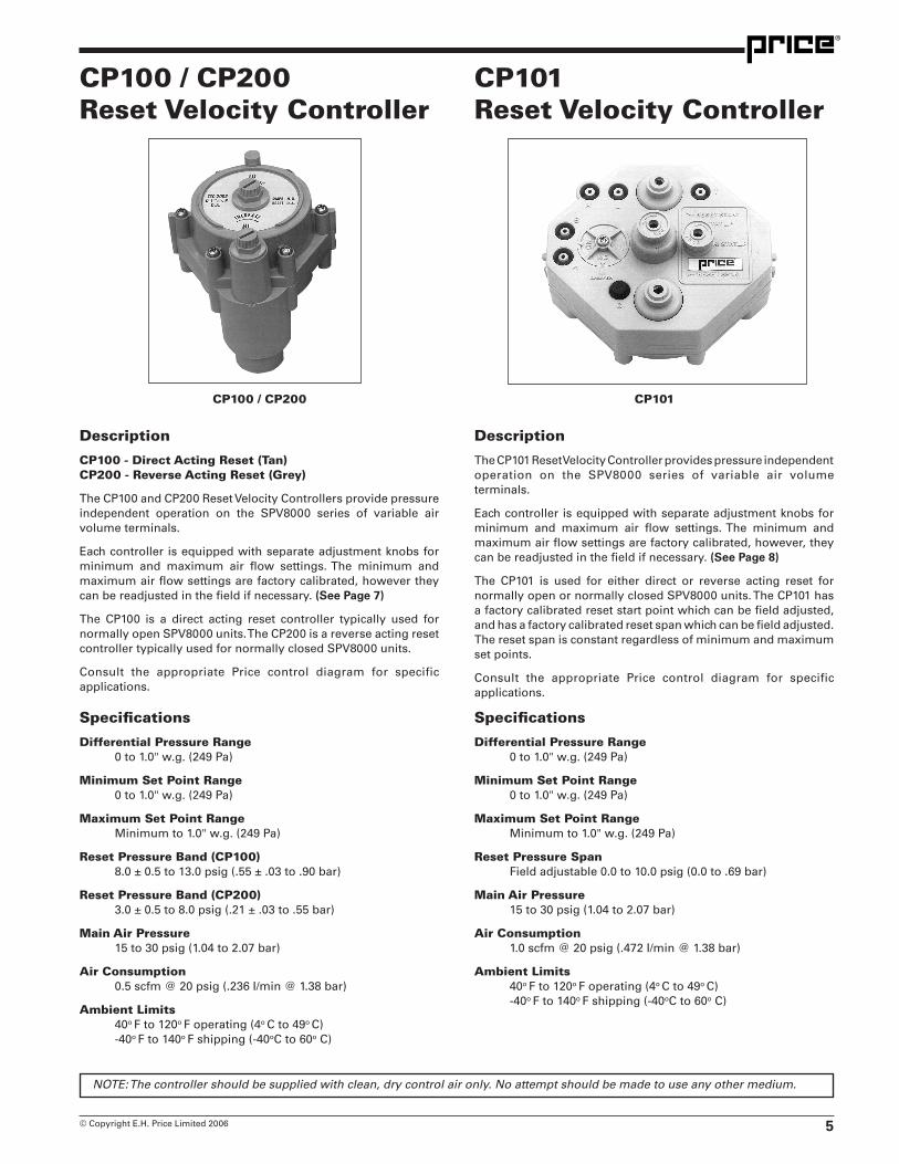
CP100 / CP200Reset Velocity Controller
CP101Reset Velocity Controller
NOTE: The controller should be supplied with clean, dry control air only. No attempt should be made to use any other medium.
CP100 / CP200 CP101
Description
CP100 - Direct Acting Reset (Tan) CP200 - Reverse Acting Reset (Grey)
The CP100 and CP200 Reset Velocity Controllers provide pressure independent operation on the SPV8000 series of variable air volume terminals.
Each controller is equipped with separate adjustment knobs for minimum and maximum air flow settings. The minimum and maximum air flow settings are factory calibrated, however they can be readjusted in the field if necessary. (See Page 7)
The CP100 is a direct acting reset controller typically used for normally open SPV8000 units. The CP200 is a reverse acting reset controller typically used for normally closed SPV8000 units.
Consult the appropriate Price control diagram for specific applications.
Description
The CP101 Reset Velocity Controller provides pressure independent operation on the SPV8000 series of variable air volume terminals.
Each controller is equipped with separate adjustment knobs for minimum and maximum air flow settings. The minimum and maximum air flow settings are factory calibrated, however, they can be readjusted in the field if necessary. (See Page 8)
The CP101 is used for either direct or reverse acting reset for normally open or normally closed SPV8000 units. The CP101 has a factory calibrated reset start point which can be field adjusted, and has a factory calibrated reset span which can be field adjusted. The reset span is constant regardless of minimum and maximum set points.
Consult the appropriate Price control diagram for specific applications.
Specifications
Differential Pressure Range 0 to 1.0" w.g. (249 Pa)
Minimum Set Point Range 0 to 1.0" w.g. (249 Pa)
Maximum Set Point Range Minimum to 1.0" w.g. (249 Pa)
Reset Pressure Span Field adjustable 0.0 to 10.0 psig (0.0 to .69 bar)
Main Air Pressure 15 to 30 psig (1.04 to 2.07 bar)
Air Consumption 1.0 scfm @ 20 psig (.472 I/min @ 1.38 bar)
Ambient Limits 40o F to 120o F operating (4o C to 49o C) -40o F to 140o F shipping (-40oC to 60o C)
Specifications
Differential Pressure Range 0 to 1.0" w.g. (249 Pa)
Minimum Set Point Range 0 to 1.0" w.g. (249 Pa)
Maximum Set Point Range Minimum to 1.0" w.g. (249 Pa)
Reset Pressure Band (CP100) 8.0 ± 0.5 to 13.0 psig (.55 ± .03 to .90 bar)
Reset Pressure Band (CP200) 3.0 ± 0.5 to 8.0 psig (.21 ± .03 to .55 bar)
Main Air Pressure 15 to 30 psig (1.04 to 2.07 bar)
Air Consumption 0.5 scfm @ 20 psig (.236 I/min @ 1.38 bar)
Ambient Limits 40o F to 120o F operating (4o C to 49o C) -40o F to 140o F shipping (-40oC to 60o C)

� © Copyright E.H. Price Limited 2006
SP300 Calibration Curves
( )
Calibration Equation VP = Q 2
VP - differentialpressureat sensor,inchesw.g.Q - airflowrate,cfmat standarddensity.K - calibrationconstant
K
Unit Size K 4 340 5 426 6 468 7 673 8 890 9 1155 10 1487 12 2141 14 3045 16 4074 24 x 16 7785
NOTES
1. Gauge taps are normally supplied with the terminal unit to allow field measurement of the differential pressure at the sensor with a manometer, magnahelic or other measuring device.
If the terminal velocity controls utilize a flow-through transducer, a proper velocity pressure reading will NOT be read at the gauge taps and the calibration curves CANNOT be used for field measurement. The flow-through transducer operates on the principle of mass flow rather than pressure differential.
Controls utilizing a dead-ended pressure transducer will allow field measurement with the gauge taps and calibration curves provided.
2. Setting flow limits for a differential pressure of less than 0.02 inches in NOT recommended. Stability and accuracy of flow limits may not be acceptable due to low velocity pressure signal. Performance will vary depending on the terminal unit controls provided.
3. For field calibration of air flow limits refer to the control contractor's documentation.

7© Copyright E.H. Price Limited 2006
CP100 / CP200 Calibration ProcedureGeneral
1. Remove the protective metal cover.
2. Aligned markings on the face and dials of the controller indicate that the factory settings are intact.
3. Remove the caps from the tees in the HI (red) and LO (green) tubes leading from the air flow sensor in the assembly inlet. Connect a differential pressure gauge to the tees. A gauge with a 0 to 1 inch w.g. scale is recommended.
4. Refer to the calibration curve for the size assembly being serviced. From the curve read the differential pressure across the sensor for the required air flow. (See Page 6)
5. Alternately, calculate the differential pressure from the equation on page 6.
CP100
6. Adjust the minimum (LO) air flow limit first.
7. Set the thermostat signal to 0 psi, or disconnect the thermostat tube to the controller.
8. Turn the minimum (LO) dial on the controller (centre knob) until the gauge reads the required differential pressure. Turn the dial slowly, allowing time for the damper actuator to complete its travel in response to the adjustments. (Verify the minimum set point by cycling the thermostat pressures).
9. Apply 15 psi minimum air pressure to the thermostat connection at the controller.
10. Turn the maximum (HI) dial on the controller (outer knob) until the gauge reads the required differential pressure. Turn the dial slowly, allowing time for the damper actuator to complete its travel in response to the adjustments. (Verify the maximum set point by cycling the thermostat pressure).
CP200
6. Adjust the minimum (HI) air flow limit first.
7. Set the thermostat signal to 0 psi, or disconnect the thermostat tube to the controller.
8. Turn the minimum (HI) dial on the controller (centre knob) until the gauge reads the required differential pressure. Turn the dial slowly, allowing time for the damper actuator to complete its travel in response to the adjustments. (Verify the minimum set point by cycling the thermostat pressure).
9. Apply 15 psi minimum air pressure to the thermostat connection at the controller.
10. Turn the minimum (LO) dial on the controller (outer knob) until the gauge reads the required differential pressure. Turn the dial slowly, allowing time for the damper actuator to complete its travel in response to the adjustments. (Verify the maximum set point by cycling the thermostat pressure).
General
12. Reconnect the thermostat tube to the controller if it has been removed during the calibration procedure.
13. Disconnect the gauge and replace the caps on the tees.
14. Replace the protective cover.
8 © Copyright E.H. Price Limited 2006
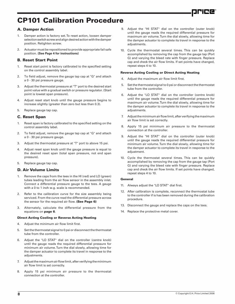
CP101 Calibration ProcedureA. Damper Action
1. Damper action is factory set. To reset action, loosen damper selection switch screw and align desired action with the damper position. Retighten screw.
2. Actuator must be repositioned to provide appropriate fail safe position. (See Page � for instructions)
B. Reset Start Point
1. Reset start point is factory calibrated to the specified setting on the control assembly label.
2. To field adjust, remove the gauge tap cap at "G" and attach a 0 - 30 psi pressure gauge.
3. Adjust the thermostat pressure at "T" port to the desired start point value with a gradual switch or pressure regulator. (Start point is lowest span pressure).
4. Adjust reset start knob until the gauge pressure begins to increase slightly (greater than zero but less than 0.3).
5. Replace gauge tap cap.
C. Reset Span
1. Reset span is factory calibrated to the specified setting on the control assembly label.
2. To field adjust, remove the gauge tap cap at "G" and attach a 0 - 30 psi pressure gauge.
3. Adjust the thermostat pressure at "T" port to above 15 psi.
4. Adjust reset span knob until the gauge pressure is equal to the desired reset span (total span pressure, not end span pressure).
5. Replace gauge tap cap.
D. Air Volume Limits
1. Remove the caps from the tees in the HI (red) and LO (green) tubes leading from the air flow sensor in the assembly inlet. Connect a differential pressure gauge to the tees. A gauge with a 0 to 1 inch w.g. scale is recommended.
2. Refer to the calibration curve for the size assembly being serviced. From the curve read the differential pressure across the sensor for the required air flow. (See Page 6)
3. Alternately, calculate the differential pressure from the equations on page 6.
Direct Acting Cooling or Reverse Acting Heating
4. Adjust the minimum air flow limit first.
5. Set the thermostat signal to 0 psi or disconnect the thermostat tube from the controller.
6. Adjust the "LO STAT" dial on the controller (centre knob) until the gauge reads the required differential pressure for minimum air volume. Turn the dial slowly, allowing time for the damper actuator to complete its travel in response to the adjustments.
7. Adjust the maximum air flow limit, after verifying the minimum air flow limit is set correctly.
8. Apply 15 psi minimum air pressure to the thermostat connection at the controller.
9. Adjust the "HI STAT" dial on the controller (outer knob) until the gauge reads the required differential pressure for maximum air volume. Turn the dial slowly, allowing time for the damper actuator to complete its travel in response to the adjustments.
10. Cycle the thermostat several times. This can be quickly accomplished by removing the cap from the gauge tap (Port G) and varying the bleed rate with finger pressure. Replace cap and check the air flow limits. If set points have changed, repeat steps 4 to 10.
Reverse Acting Cooling or Direct Acting Heating
4. Adjust the maximum air flow limit first.
5. Set the thermostat signal to 0 psi or disconnect the thermostat tube from the controller.
6. Adjust the "LO STAT" dial on the controller (centre knob) until the gauge reads the required differential pressure for maximum air volume. Turn the dial slowly, allowing time for the damper actuator to complete its travel in response to the adjustments.
7. Adjust the minimum air flow limit, after verifying the maximum air flow limit is set correctly.
8. Apply 15 psi minimum air pressure to the thermostat connection at the controller.
9. Adjust the "HI STAT" dial on the controller (outer knob) until the gauge reads the required differential pressure for minimum air volume. Turn the dial slowly, allowing time for the damper actuator to complete its travel in response to the adjustment.
10. Cycle the thermostat several times. This can be quickly accomplished by removing the cap from the gauge tap (Port G) and varying the bleed rate with finger pressure. Replace cap and check the air flow limits. If set points have changed, repeat steps 4 to 10.
General
11. Always adjust the "LO STAT" dial first.
12. After calibration is complete, reconnect the thermostat tube to the controller if is has been removed during the calibration procedure.
13. Disconnect the gauge and replace the caps on the tees.
14. Replace the protective metal cover.

�© Copyright E.H. Price Limited 2006
General
Troubleshooting Guide 1. Locate thermostat and cycle — direct acting stat will bleed on
heating.
2. Confirm box size and rating with drawing and box schedule (check label on terminal). Check position of controller to ensure it is installed level.
3. For CP101 controller, check the damper selector switch at the face of the controller. Ensure that switch is set in the correct mode.
4. Visually check piping and connections to box controls and motor.
Blue — Main Air (M) White — Thermostat (T) Yellow — Actuator (B) Red — High Port (X - CP100) (Y - CP200) (H - CP101) Green — Low Port (Y - CP100) (X - CP200) (L - CP101)
5. Confirm caps are securely in place on the tees in the sensor lines between the sensor and the controller.
6. Confirm that the "G" port cap on controller is in place.
7. Confirm main air pressure (15 psi minimum - 25 psi maximum).
8. Confirm thermostat pressure. Cycle thermostat from full cooling to full heating.
9. Confirm actuator pressure from controller by cycling thermostat.
10. Confirm actuator operation by stroking actuator with a hand pump noting at what pressure the actuator begins to stroke and is fully stroked.
1. Connect a differential pressure gauge (0 - 1.0" w.g.) to the tees in the sensor lines between the sensor and the controller.
2. Check velocity pressure reading and compare with the value indicated on the controller label.
3. If the velocity pressure is below the specified value and the damper is fully open, this would indicate insufficient inlet duct static pressure, starving.
1. If the damper of the control assembly is partially closed, this indicates the unit is under control.
2. If the velocity pressure indicated by the gauge does not match the specified value, recalibrate the controller according to the procedures outlined in this manual.
1. If the supply air flow measured by other means (pitot tube traverse, summation of outlets) is incorrect, inspect the inlet connection to the control assembly.
2. Price recommends a minimum of 3 duct diameters of straight inlet duct, same size as inlet, between the inlet and any transition, take off or fitting.
• Check the low pressure tubing connection on the controller to see if tubing is connected.
• The HI sensor port or control line may be plugged. Clear the passage with compressed air.
• The LO sensor port or control line may be plugged. Clear the passage with compressed air.
If Velocity Pressure is Below Specified Value and the Damper is Fully Open
If the Velocity Pressure Indicated by the Gauge Does Not Match the Specified Value.
If the Damper Remains Fully Open, but Sufficient Static Pressure Exists at the Inlet
If Velocity Pressure Indicated by the Gauge is Lower then Specified but Actual Air Supply Exceeds Design Flow
If Supply Air Flow Measured by Other Means is Incorrect
If the Damper Remains Fully Closed
10 © Copyright E.H. Price Limited 2006

11© Copyright E.H. Price Limited 2006
2975 Shawnee Ridge CourtSuwanee, Georgia USA 30024Ph: 770.623.8050 Fax: 770.623.6404
IN THE UNITED STATES• US Head Office, Laboratory & Testing
Facilities, Manufacturing Facilities & Distribution Warehouse in Atlanta, Georgia
• US Representatives in most major cities
999 North Thornton RoadCasa Grande, Arizona USA 85222-3809Fax: 520.423.0517
IN THE UNITED STATES• Manufacturing Facilities & Distribution Ware-
house in Casa Grande, Arizona
• US Representatives in most major cities
638 Raleigh StreetWinnipeg, Manitoba Canada R2K 3Z9Ph: 204.669.4220 Fax: 204.663.2715
IN CANADA• Head Office, Export Sales Office, Laboratory & Testing Facilities, Manufacturing Facilities & Distribution
Warehouse in Winnipeg, Manitoba
• Canadian Sales Offices in most major cities
The founding principles of our company have never changed – business integrity, first class service and a commitment to people.Price manufacturing endeavours arose from our belief that we could supply superior products and services at a reasonable price. Our mission is to become the worldwide supplier of preference for air distribution products and services. You can rely on Price – our products and services – with confidence.
Product Improvement is a continuing endeavour at Price. Therefore, specifications are subject to change without notice.Consult your Price sales representative for current specifications or more detailed information.
Warranty: The Company warrants and guarantees that all goods within this catalog that have been manufactured by the Company have been manufactured in accordance with the specifications published herein and will be free from defects in material and workmanship for a period of twelve (12) months from the date of Bill of Lading issued by the Company. The Company will replace defective product at its option, but will not be responsible for labor or material charges in replacing product or consequential damages. Any installation not conforming with the Company's specifications, manuals, bulletins or instructions or any misuse or any modification not authorized by the Company voids this warranty. This warranty is in lieu of all Provincial, State, and Federal statutory warranties and the conditions herein are in substitution and replacement of such warranties, statutory or otherwise.
® Price is a registered trademark of E.H. Price Limited. © 2006. Lithographed in Canada 02/06
Your Local Price Represntative: