Sprinter 2006 2.2_3.0_d_e
20
WARNING! Hazard warning: Incorrect installation or repair of Webasto heating systems may cause a fire or result in the emission of carbon monoxide, which can be fatal. Serious or fatal injuries can be caused as a result. Specialist company training, technical documentation, specialized tools and equipment are required to install and repair Webasto heating and cooling systems. NEVER attempt to install or repair Webasto heating or cooling systems if you have not successfully completed the company training and thereby acquired the required technical skills, or if you do not have access to the required technical documentation, tools and equipment needed to carry out correct installation and repairs. ALWAYS follow all Webasto installation and repair instructions and observe all warnings. Webasto does not accept any liability for defects and damage that are attributable to installation by untrained staff. Feel the drive Mercedes Sprinter Diesel from Model Year 2006 For left-hand drive vehicles only Vehicles without air conditioning not tested Ident. No.: 9016210A_EN Fee Euro 10 © Webasto AG Water Heater Unit Thermo Top C Motorcaravan Additional Heater Installation Instructions e1 00 0002
-
Upload
el-petregas -
Category
Automotive
-
view
37 -
download
1
Transcript of Sprinter 2006 2.2_3.0_d_e

WARNING!
Hazard warning:
Incorrect installation or repair of Webasto heating systems may cause a fire or result in the emission of carbon monoxide, which can be fatal. Serious or fatal injuries can be caused as a result.
Specialist company training, technical documentation, specialized tools and equipment are required to install and repair Webasto heating and cooling systems.
NEVER attempt to install or repair Webasto heating or cooling systems if you have not successfully completed the company training and thereby acquired the required technical skills, or if you do not have access to the required technical documentation, tools and equipment needed to carry out correct installation and repairs.
ALWAYS follow all Webasto installation and repair instructions and observe all warnings.
Webasto does not accept any liability for defects and damage that are attributable to installation by untrained staff.
Feel the drive
Mercedes SprinterDieselfrom Model Year 2006For left-hand drive vehicles onlyVehicles without air conditioning not tested
Ident. No.: 9016210A_EN Fee Euro 10 © Webasto AG
Water Heater Unit
Thermo Top C Motorcaravan Additional Heater
Installation Instructions
e100 0002

22
Mercedes Sprinter
Validity
Vehicle and engine types, equipment variants and national specifications not listed in these installation instructions have not been tested. However, installation according to these installation instructions may be possible.The installation location of a digital timer and changeover switch should be confirmed with the end customer before installation.
Manufacturer ModelMercedes Sprinter
Engine type Engine model Output in kW Displacement in cm³2.2 cDi Diesel 80 21482.2 cDi Diesel 95 21482.2 cDi Diesel 110 21483.0 cDi Diesel 135 2987
Validity 2Heater Unit/Installation Kit 3Foreword 3General Instructions 3Special Tools 3Explanatory Notes on Document 4Preliminary Work 5Heater unit installation location 5Preparing installation location 6Installing heater unit 7
Exhaust system 8Coolant connection 9Preparing electrical system 12Electrical Connections 13Fuel Connection 15Combustion air 18Final Work 19Template for Fuel Standpipe 20
Table of Contents

33
Mercedes Sprinter
Heater Unit/Installation Kit
ForewordThe installation instructions apply to the Mercedes Sprinter vehicles with a Diesel engine- For the validity, see page 2 - from model year 2006 and later, assuming technical modifications to the vehicle do not affect installation, any liability claims excluded. Depending on the vehicle version and equipment, modifications may be necessary during installation with respect to these installation instructions.
However, where this is the case the stipulations in the "installation instructions" and "operating and maintenance instructions" for the Thermo Top C Motorcaravan should be observed.The corresponding rules of technology and any information from the vehicle manufacturer should be observed during the installation work.
General InstructionsInstallation should be carried out according to the general, standard rules of technology. Unless specified otherwise, fasten hoses, lines and wiring harnesses to original vehicle lines and wiring harnesses using cable ties.Sharp edges should be fitted with edge protectors (split-open plastic hose).Spray unfinished body areas, e.g. drilled holes, with anti-corrosion wax (Tectyl 100K, Order No. 111329).
Special Tools- Torque wrench for 2.0 - 10 Nm- Hose clamping pliers- Riveting pliers
Quantity Description Order No.:1 Basic delivery scope of Thermo Top C Motorcaravan 9015824A1 Installation kit for Mercedes Sprinter Diesel 2006 Motorcaravan 9016207A

44
Special features are highlighted using the following symbols:
Mechanical system
Electrical system
Coolant connection
Fuel connection
Exhaust system
Combustion air
The arrow in the vehicle icon indicates the position on the vehicle and the viewing angle.
Mercedes Sprinter
Specific risk of injury or fatal accidents.
Specific risk of damage to components.
Specific risk of fire or explosion.
Reference to general installation instructions of Webasto components or to the manufacturer's vehicle-specific documents.
Reference to a special technical feature.
i
Explanatory Notes on Document
To provide you with a quick overview of the individual working steps, you will find an identification mark on the outside top right corner of the page in question.

Mercedes Sprinter
Preliminary Work
WARNING!
- Disconnect the battery "earth" or "ground" connection.- Depressurize the cooling system.- Copy the factory number from the original type label to the duplicate type label.- Remove years that do not apply from the duplicate label.- Attach the duplicate label (type label) in the appropriate place.- Remove the entire air filter- Open the fuel tank cap, ventilate the tank.- Close the tank cap again.- Remove the fuel tank- Remove the fuel-tank sending unit in accordance with the manufacturers specifications- Remove the glove compartment and remove the service door for the onboard toolkit- Unclip the jump-starting positive connection point- Disconnect the radiator expansion tank and set it aside- Remove the instrument panel trim at the lower left and between the lighting switch and the steering
column
Heater unit installation location
1 Heater unit
Installation location
1
1
5
Mercedes Sprinter
Preparing installation location
1 Unscrew original vehicle nut2 Lay aside original vehicle return line
Preparing installation location
1 Bracket2 Angle bracket3 M6x20 bolt, flanged nut [2x]
Preassem-bling bracket
Loosely fasten bracket 5 with nut 4 and align, copy hole patterns 2 and 3 to frame side member 1.
2 7.0 mm dia. hole [2x] in frame side member3 4.5 mm dia. hole [2x] in frame side member
Copying hole pattern
1 M6x20 bolt, washer, flanged nut [2x]2 6.3x19 self-tapping screw, large diameter
washer [2x]3 M8 nut, washer, spring lockwasher
Installing bracket
2
1
2
3
3
1 2
3
4
4
2 3
5
3 21
5
3
1 2 2 1
6

Mercedes Sprinter
Installing heater unit
Tighten EJOT screws to 10 Nm!
1 Hose D, 20 mm dia., l=100 mm, connecting pipe 18/20, 27 mm dia. spring clip [2x]
2 Hose section, 10 mm dia. Caillau clamp3 Ejot stud, long, 8 mm washer4 Ejot stud, long, 5 mm washer [2x]
Preassem-bling heater unit
1 Fuel line, 10 mm dia. Caillau clamp2 Flanged nut, washer3 Flanged nut, washer [2x]
Installing heater unit
6
1 2
4
3
7
1
3 2
7

Mercedes Sprinter
Exhaust system
1 Exhaust pipea = 460 mm
2 Exhaust end sectionb = 410 mm
Discard section XPreparing exhaust pipe
1 Bend perforated bracket as shown,p-clamp, M6x20 bolt, flanged nut
2 Exhaust end section3 Hose clamp [3x]4 Muffler5 Exhaust pipe6 Angle bracket, M6x20 bolt, flanged nut Preassem-
bling exhaust pipe
1 4.5 mm dia. hole, 6.3x13 self-tapping screw, large diameter washer
2 Exhaust pipe
Installing exhaust pipe
1 7.0 mm dia. hole, M6x20 bolt, flanged nut, large diameter washer [2x]
2 Exhaust end section
Installing end section
a b
1 2
X
8
5
1 2
6
3
3
4 3
1
2
9
1
2 10
8
Mercedes Sprinter
Coolant connection
WARNING!Tighten all hose clamps to 2.0 + 0.5 Nm.Any coolant running off should be collected using an appropriate container!Install hoses so that they are kink-free. Unless specified otherwise, always fasten using cable ties. Position hose clamps and spring band clamps so that no other hose can be damaged.
Coolant routing diagram
All hose clamps without a specific designation = 20-27 mm diaAll spring clips without a specific designation = 27 mm dia.
Motor
Wärme-tauscher
Wärme-tauscher
Motor
HG
E
DC
A 18x20x18
Ø 25
Ø 27
Ø 25
B
F
Ø 18x18Ø 18x20
Wärme-tauscher
Motor
HG
E
DC
A 18x20x18
Ø 25
Ø 25
Ø 25
B
F
Ø 18x18Ø 18x20
Ø 25
Heat exchanger
9

Mercedes Sprinter
a = 800 mme = 1,020 mm
Discard section XCutting 18 mm coolant hose to length
c = 80 mmd = 100 mmf = 850 mm
Discard section XCutting 20 mm coolant hose to length
B Molded hose 9007982A
Preassem-bling hose group
Secure hose group with spacer brackets.
1 T-piece, 18x20x182 Thermostat3 Check valve (watch direction of flow)
Preassem-bling hose group
e a
XAE
f c d
XDCF
11
BE A
F
12
23
1
10

Mercedes Sprinter
a = 25 mm
1 Original vehicle hose to engine inlet2 Original vehicle hose to heater exchanger
outlet3 Original vehicle hose to heater exchanger
inlet4 Original vehicle hose from engine outlet;if
clip present, remove and discard
Cutting points
Con-nection on heater unit
Secure hose group 1 on coolant reservoir with cable ties.
Routing in engine compart-ment
Before connecting, fill the coolant hoses with coolant.
Con-nection on heat exchanger
13
2 3 41
a a
14
D
C
15
1 1
16
E
F
A
11

Mercedes Sprinter
Preparing electrical system
1 Uncrimp red (rt) wire and remove2 Uncrimp green/white (gn/ws) wire and
remove connector3 Uncrimp black (sw) wire and remove4 Replace 25 A fuse with 3 A fuse
Preparing wiring harness
1 Extend green/white (gn/ws) wire green/white (gn/ws) wire provided
2 Green/white (gn/ws) wire in protective sleeving
Preparing wiring harness
1 Original vehicle stud bolt and flanged nut2 Perforated bracket angled down3 Relay, M5x16 bolt, washers, nut4 Fuse holder retaining plate, relay, M5x6
bolt, washers, nut
Fuse holder, relay
1 Original vehicle stud bolt and flanged nut
Ground connection for heater unit
17
2
3
4
1
18
1
2
19
1
4
23
20
1
12

Mercedes Sprinter
Electrical Connections
Wiring harness pass through
1 Protective rubber plug, hole from inside
Connection for IPCU
1 Original green (gn) vehicle wire2 Red (rt) wire from IPCU3 Black (sw) wire from IPCU
Wiring harness installation diagram
Ground connection for IPCU
1 Original vehicle stud bolt, flanged nut
Digital timer, changeover switch
1 Digital timer2 Changeover switch
21
1
22
1
23
br
bl
gn/ws Do not install the metering pump cable harness until later together with fuel pipe along the original vehicle fuel lines on the underbody
i
23
1
24
1 2
13

Mercedes Sprinter
Wiring diagram for automatic air-condition-ing and manual air-condition-ing
Webasto components Components of Mercedes Sprinter
Colors and symbols
Legend
HG Heater unit TT-C KB Air-conditioning control element
rt red
X1 6-pin connector GRr Fan controller ws whiteIPCU IPCU module M2n1 4-pin connector sw black
A2 27-pin connector br browngn greenGR gray
X Cutting pointWiring colors may vary.
85 86
A
E
15
IPCUrt
sw
br
Webasto
31
3015
Sprinter
gn/ws
HG4X1
A225
KB
M2n1 2
GRr
gr
gr
i
14
Mercedes Sprinter
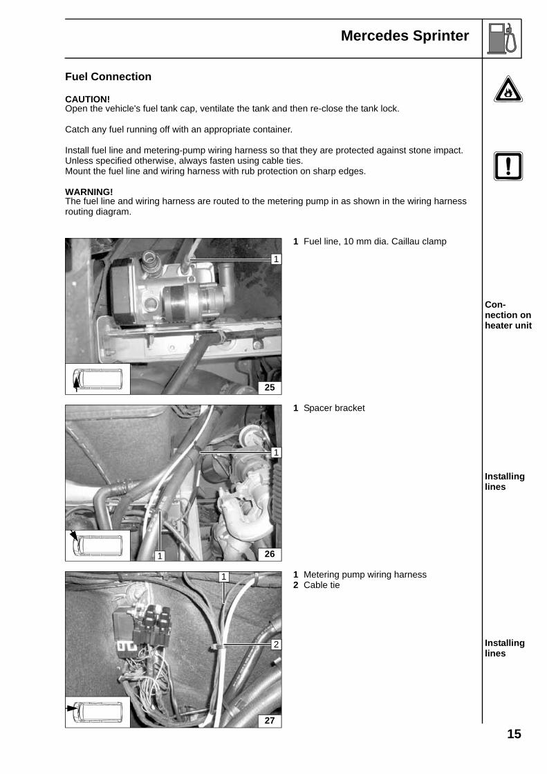
Fuel Connection
CAUTION!Open the vehicle's fuel tank cap, ventilate the tank and then re-close the tank lock.
Catch any fuel running off with an appropriate container.
Install fuel line and metering-pump wiring harness so that they are protected against stone impact. Unless specified otherwise, always fasten using cable ties.Mount the fuel line and wiring harness with rub protection on sharp edges.
WARNING!The fuel line and wiring harness are routed to the metering pump in as shown in the wiring harness routing diagram.
1 Fuel line, 10 mm dia. Caillau clamp
Con-nection on heater unit
1 Spacer bracket
Installing lines
1 Metering pump wiring harness2 Cable tie
Installing lines
25
1
26
1
1
27
2
1
15

Mercedes Sprinter
1 Metering pump wiring harness2 Fuel line
Installing lines
Unclip original vehicle positive wiring harness
1 M6x20 bolt, washer, flanged nut2 Metering pump mounting3 Metering pump
Installing metering pump
Fuel line from fuel standpipe on intake side of metering pump [side without connector].Check the position of the components; adjust if necessary. Check that they have free clearance.
1 Metering pump wiring harness2 Fuel line to heater unit3 Hose section, 10 mm dia. hose clamps
[2x].4 Fuel line from fuel standpipe
Con-nection to metering pump
Remove fuel-tank sending unit in accordance with manufacturer's instructions.
a = 8 mmb = 15 mm
1 Fuel-tank sending unit2 Copy hole pattern, 6 mm dia. hole
Removing fuel
28
1
2
29
2
3
1
30
2
3
1
4
3
31
1
2
a
b
16

Mercedes Sprinter
Shape fuel standpipe according to template, cut to length, preassemble and install, see "installation instructions".
1 Fuel-tank sending unit2 Fuel standpipe3 Hose section,10 mm dia. Caillau clamp
Installing fuel standpipe
Shape fuel standpipe according to template, cut to length and install, see "installation instructions".
1 Fuel standpipe2 Fuel-tank sending unit
Installing fuel standpipe
Install fuel-tank sending unit in accordance with manufacturer's specifications.
1 10 mm dia. Caillau clamp2 Fuel-tank sending unit3 Remaining end of Mecanyl fuel line
Con-necting fuel line
32
1
23
i
33
1
2
i
34
1 2
3
17

Mercedes Sprinter
Combustion air
1 27 mm dia. hose clamp2 Combustion-air intake pipe3 Combustion-air intake muffler
Installing intake pipe
Fasten combustion-air intake muffler 1 on coolant hose with cable tie 2.
Fastening muffler
352
1
3
i
36
1 2
18

Mercedes Sprinter
Final Work
WARNING!Reassemble the disassembled components in reverse order.Check all hoses, hose, spring and Caillau clamps, as well as all electrical connections for firm seating.Secure all loose cables using cable ties.Only use manufacturer-approved coolant.Spray the heater unit components with anti-corrosion wax (Tectyl 100K, Order No. 111329).
- Connect the battery- Start the engine, bleed the coolant circuit according to the vehicle manufacturer's instructions and
top up coolant- Set the digital timer.- Set the manual air conditioning or automatic air conditioning according to the "operating
instructions for the end customer".- Check the proper operation of the additional heater, see the operating instructions/installation
instructions.- Attach the "Switch off additional heater before refueling" sticker to the left-hand B-pillar.
i
Webasto AGPostfach 80 - 82132 Stockdorf, Germany - Hotline +49-(0)1805-932278Hotfax +49-(0)395-5592-353 - http://www.webasto.de
Feel the drive
Printed in Germany 11/06Printed by: Steffen
20
Mercedes Sprinter
0
100 mm
100 mm
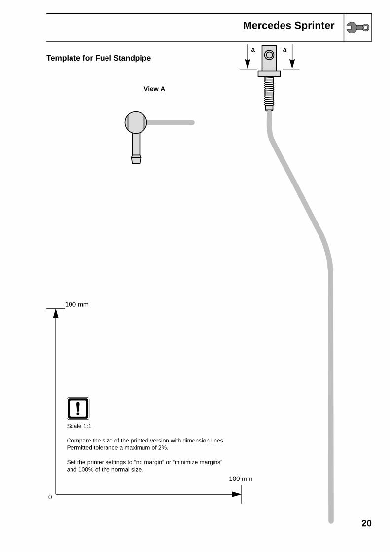
Scale 1:1
Compare the size of the printed version with dimension lines.Permitted tolerance a maximum of 2%.
Set the printer settings to “no margin” or “minimize margins” and 100% of the normal size.
Template for Fuel Standpipea a
View A