Worksheet Practice 12-4 60º 120º 60º Mrs. Rivas International Studies Charter School.

SPRING-BACK PREDICTION OF MILD STEEL SHEET ON 60º AIR BENDING
MOHD ZUHAIRI BIN MD ZOHIR
Report submitted in fulfilment of
The requirements for the award of the degree of
Bachelor of Mechanical Engineering
Faculty of Mechanical Engineering
UNIVERSITI MALAYSIA PAHANG
DECEMBER 2010

ii
UNIVERSITI MALAYSIA PAHANG
FACULTY OF MECHANICAL ENGINEERING
I certify that the project entitled “Spring-back prediction of mild steel sheet on 60º air
bending “is written by Mohd Zuhairi Bin Md Zohir. I have examined the final copy of
this project and in our opinion; it is fully adequate in terms of scope and quality for the
award of the degree of Bachelor of Engineering. I herewith recommend that it be
accepted in partial fulfilment of the requirements for the degree of Bachelor of
Mechanical Engineering.
Examiner Signature

iii
SUPERVISOR’S DECLARATION
I hereby declare that I have checked this project and in my opinion, this project is
adequate in terms of scope and quality for the award of the degree of Bachelor of
Mechanical Engineering.
Signature:
Name of Supervisor: JASRI MOHAMAD
Position: LECTURER OF MECHANICAL ENGINEERING
Date: 6 DICEMBER 2010

iv
STUDENT’S DECLARATION
I hereby declare that the work in this project is my own except for quotations and
summaries which have been duly acknowledged. The project has not been accepted for
any degree and is not concurently submitted for award of other degree.
Signature:
Name: MOHD ZUHAIRI BIN MD ZOHIR
ID Number: MA07059
Date: 6 DICEMBER 2010
vi
ACKNOWLEDGEMENTS
I am grateful and would like to express my sincere gratitude to my supervisor
Mr. Jasri Mohamad for his germinal ideas, invaluable guidance, continuous
encouragement and constant support in making this research possible. He has always
impressed me with his outstanding professional conduct, his strong conviction for
science, and his belief that a bachelor program is only a start of a life-long learning
experience. I appreciate his consistent support from the first day I applied to graduate
program to these concluding moments. I am truly grateful for his progressive vision
about my training in science, his tolerance of my naive mistakes, and his commitment to
my future career
My sincere thanks go to all my labmates and members of the staff of the
Mechanical Engineering Department, UMP, who helped me in many ways and made
my stay at UMP pleasant and unforgettable.
I acknowledge my sincere indebtedness and gratitude to my parents for their
love, dream and sacrifice throughout my life. I acknowledge the sincerity of my parents-
in-law, who consistently encouraged me to carry on my higher studies in Malaysia. I
cannot find the appropriate words that could properly describe my appreciation for their
devotion, support and faith in my ability to attain my goals. Special thanks should be
given to my committee members. I would like to acknowledge their comments and
suggestions, which was crucial for the successful completion of this study.

vii
ABSTRACT
This report deals with the deformation of a spring-back on 60° air bending. Now days,
many research and study have been done on a spring-back. In sheet metal bending, a flat
part is bent using a set of punches and dies. In this thesis, punches and die are referred
to as tools. The punch and the dies are mounted on a press brake, which control the
relative motion between the punch and die and provides the necessary bending pressure.
In this thesis, the spring-back is done by using both experimental and simulation using
FEA software which is ABAQUS 6.7. The material use in this project is mild steel with
1 mm thickness. The size of the specimen is 100 mm x 100 mm. The experimental is
done fist follow by the simulation. The specimen required in this project is 10
specimens. The Profile Projector machine is use to measure the angle of the sheet metal
in the experiment. In the simulation, 2D drawing of the model have been made using
ABAQUS 6.7. The punch, die and the sheet metal is main part in the drawing. The sheet
metal then is defined as a rigid body in the software. The meshing has been done to
sheet metal with 0.5 mm of the mesh size. After all the simulation is done, several node
has been taken to measure the angle by using AutoCAD software. 8 nodes is taken an
then transfer it to the AutoCAD software. The result from both experimental and
simulation then be compared. The spring-back value in experimental is 62.3° while in
the simulation the value is 62°.
viii
ABSTRAK
Laporan ini berkaitan fenomena “spring-back” yang berlaku pada 60° pembengkokkan
secara tergantung. Dewasa ini, banyak kajian telah dilakukan pada “spring-back”.
Dalam lembaran logam membengkok, bahagian datar akan di bengkokkan
menggunakan satu set pemukul dan acuan. Dalam tesis ini, pemukul dan acuan disebut
sebagai alat. Pemukul dan acuan sudah dipasang pada mesin, yang mengendalikan
gerakan relatif antara pemukul dan acuan dan memberikan tekanan membengkokkan
diperlukan. Dalam tesis ini, fenomena “spring-back” dilakukan dengan menggunakan
perisian FEA dan eksperimen. Perisian yang digunakan adalah ABAQUS 6,7. Bahan
yang digunakan dalam projek ini adalah kepingan besi dengan ketebalan 1 mm. Saiz
spesimen adalah 100 mm x 100 mm. Spesimen yang diperlukan dalam projek ini adalah
10 spesimen. Mesin“Profile Projector” digunakan untuk mengukur sudut lembaran
logam. Dalam simulasi, 2D gambar model telah dibuat dengan menggunakan ABAQUS
6.7. Pemukul, acuan dan lembaran logam adalah bahagian utama dalam gambar. Logam
lembaran kemudian ditakrifkan sebagai benda tegar dalam perisian. “Meshing” telah
dilakukan untuk kepingan logam dengan 0,5 mm saiz mesh. Setelah semua simulasi
dilakukan, beberapa node telah diambil untuk mengukur sudut dengan menggunakan
perisian AutoCAD. 8 node telah diambil kemudian dipindah ke perisian AutoCAD.
Keputusan daripada kedua-dua percubaan dan simulasi kemudian akan dibandingkan.
Nilai “spring-back” dalam eksperimen adalah 62,3 ° manakal pada simulasi pula nilai
adalah 62 °.
ix
TABLE OF CONTENTS
Page
SUPERVISOR’S DECLARATION iii
STUDENT’S DECLARATION iv
ACKNOWLEDGEMENTS vi
ABSTRACT vii
ABSTRAK viii
TABLE OF CONTENTS ix
LIST OF TABLES xii
LIST OF FIGURES xiii
LIST OF SYMBOLS xv
LIST OF ABBREVIATIONS xvi
CHAPTER 1 INTRODUCTION
1.1 Introduction 1
1.2 Project Background 1
1.2.1 Bending Principle 1
1.3 Problem Statement 3
1.4 Project Objective 3
1.5 Scope of the Project 3
CHAPTER 2 LITERATURE REVIEW
2.1 Introduction 4
2.2 Theory of Sheet Metal 4
2.3 Common Types of Bending 5
2.3.1 V-Bending 5
2.3.2 U-Bending 6
2.3.3 Wiping Die Bending (L-Bending) 6
2.4 Bend Allowance 7
2.5 Air Bending 10

x
2.6 Spring-Back V-Bending 11
2.6.1 Compensation for Spring-Back 12
2.7 Material 13
2.7.1 Low Carbon Steel 13
2.8 Previous Study of Spring-Back in V-Bending 13
2.8.1 An experimental study on the examination of spring-back
with several thickness and properties in bending dies
13
2.8.2 Determining spring-back amount of steel sheet metal has
0.5 mm thickness in bending dies
18
CHAPTER 3 METHODOLOGY
3.1 Introduction 23
3.2 Flow Chart 24
3.3. Simulation 25
3.3.1 Material Properties 26
3.3.1.1 Elastic Properties 26
3.3.1.2 Plastic Properties 27
3.3.2 Material Modelling 28
3.4 Experimental 28
3.4.1 Mechanical Drawing 28
3.4.2 Bending Machine 29
3.4.3 Material 30
3.3.4 Process 30
CHAPTER 4 RESULTS AND DISCUSSION
4.1 Introduction 32
4.2 FEA Result Analysis 32
4.3 Experimental Result 36
4.4 Result Summary 38
CHAPTER 5 CONCLUSION AND RECOMMENDATIONS
5.1 Introduction 39
5.2 Conclusion 39
5.3 Recommendation 39

xi
REFERENCES 41
APPENDICES 42
A Gantt chart for Final Year Project 1 42
B Gantt chart for Final Year Project 2 43

xii
LIST OF TABLES
Table No. Title Page
2.1 Chemical composition of materials 14
2.2 Bending angle of sheet metal 0.5 mm thickness (method 1) 19
2.3 Bending angle of sheet metal 0.5 mm thickness (method 2) 19
3.1 Low carbon steel carbon percentage and Young’s Modulus 26
3.2 Plastic properties data 27
3.3 Lower die specification 30
3.4 Upper punch specification 30
4.1 Nodes number 34
4.2 Experiment result of bending analysis 36
4.3 Spring-back angle for experiment and simulation 38

xiii
LIST OF FIGURES
Figure No. Title Page
1.1 Beam 1
1.2 Beam is flexed 2
2.1 Diagram of V-bending 5
2.2 Diagram of U-bending 6
2.3 Diagram of L-bending 7
2.4 Bend allowance 8
2.5 Bend deduction 8
2.6 Diagram of K-factor 9
2.7 Diagram to calculate bend allowance using K-factor 10
2.8 Diagram of air-bending 11
2.9 Spring-back in bending 12
2.10 Spring-back graph of 0.50 mm (method 1) 16
2.11 Spring-back graph of 0.75 mm (method 1) 16
2.12 Spring-back graph of 1.00 mm (method 1) 17
2.13 Spring-back graph of 0.5 mm (method 2) 17
2.14 Spring-back graph of 0.75 mm (method 2) 17
2.15 Spring-back graph of 1.00 mm (method 2) 17
2.16 Spring-back graphic of 0.5 mm steel sheet metal yielded by using
the first method and yielded polynomial curve equation
20
2.17 Spring-back graphic of 0.5 mm steel sheet metal yielded by using
the second method and yielded polynomial curve equation
20
2.18 Graphic were four methods are combined (bending angle vs
spring-back angle)
21
3.1 FEA modelling 25
3.2 Stress-strain graph 27
3.3 CAD drawing 28

xiv
3.4 TrumaBend V85S bending machine 29
3.6 Plate press by punch 31
3.7 Mitutoyo profile projector 31
4.1 Punch press the plate 33
4.2 Punch is released 34
4.3 Node coordinate develop in CAD software 35
4.4 V-bending specimen 36
4.5 Angle measure using profile projector machine 37

xv
LIST OF SYMBOL
�� Actual radius
�� Radius after spring-back
Y Yield strength
E Elastic modulus
α Angular
Lt Total Flat Length
ν Poisson Ratio
ε Plastic Strain
σ Yield Stress

xvi
LIST OF ABBREVIATIONS
FEA Finite Element Analysis
CAD Computer-aided Design
BD Bend Deduction
BA Bend Allowance
2D 2 Dimension
CHAPTER 1
INTRODUCTION
1.1 INRODUCTION
This chapter will discuss about the project background, problem state, project
objective and the scope of the project.
1.2 PROJECT BACKGROUND
In sheet metal bending, a flat part is bent using a set of punches and dies. In this
thesis, punches and die are referred to as tools. The punch and the dies are mounted on a
press brake, which control the relative motion between the punch and die and provides
the necessary bending pressure.
1.2.1 Bending Principle
Take a beam 1m long if it starts as a straight beam then the length measured
along the top face with the aid of a tape measure is one meter. Similarly the bottom face
will also be one meter as shown in Figure 1.1 below.
Figure 1.1: Beam
1m
1m
A
C D
B

2
When the beam was straight, AB was equal to CD, but mow by visual inspection
it is now obvious that this is not the case, once the beam is flexed. The beam as shown
is said to be ‘hogging’ so that the upper face is longer than the bottom face as shown in
Figure 1.2 below.
Figure 1.2: Beam is flexed
If the beam is solid then there cannot be any migration of material from the
bottom to the top reaches of the beam (because solids are generally rigid or semi-rigid).
The only way the hogging can occur is if AB is stretched further than CD by the
bending action.
If AB remains 1m then CD must be shorter, the bottom face is therefore
compressed and the fibres beneath the surface of the bottom face experience
compressive stress. If however CD remains 1m then the upper face AB must have been
stretched and the fibres beneath the upper surface are subject to tensile stress.
The two conditions just described represent two extremes. In most flexing
situations, reality is somewhere between the two and in many cases is close to halfway
between the two, such that length XY midway between AB / CD remains 1m. Therefore
AB is stretched and CD is compressed.
The third situation is that assumed in the theory of simple bending generally
used for analysis of bending and buckling.
A C D
B X Y
3
1.3 PROBLEM STATEMENT
Whenever forming metals, some spring-back occurs. The cause of this spring-
back is the residual stress that is an inevitable result of cold working metals. For
example, in a simple bend, residual compressive stress remains on the inside of the
bend, while residual tensile stress is present on the outside radius of the bend. The most
common method of correcting for spring-back is to overbend the material to obtain the
desired shape after forming. Simply stated, in a bend, residual compressive stress
remains on the inside of the bend, while residual tensile stress is present on the outside
radius of the bend.
1.4 PROJECT OBJECTIVE
The objectives of this study are:
a) To evaluate and compare the most reliable material modeling in finite element
analysis (FEA) predict in spring-back.
b) To apply finite element analysis (FEA) technology in sheet metal forming of
bending.
1.5 SCOPE OF THE PROJECT
The scopes of the project are limited to:
a) Develop 2D modeling of V-bending in Finite Element software
b) Analyze 2D modeling Finite Element software purpose for spring-back.
c) Conduct experiment for V-bending using bending machine (air bending).
d) Analyze the simulation and experiment result.
e) Compare the result from both tasks.

CHAPTER 2
LITERATURE REVIEW
2.1 INTRODUCTION
In this chapter it will discuss about theory of the sheet metal, the common types
of bending bend allowance, air bending, spring-back in v-bending, material, and some
previous study in v bending.
2.2 THEORY OF SHEET METAL
Sheet metal forming differs from other deformation processes such as rolling,
hot extrusion and wire drawing in that it is a non-steady-state process. A deformation
zone exists into which all the material enters and is subjected to a fixed deformation
pattern before exiting while, in sheet metal forming, different deformation modes can
operate in differ areas of the sheet or, subsequently, in the same area, initiated by the
interaction between a contoured piece of sheet metal with shaped tools, which are
usually installed in a power press.
In sheet metal we can use it to bend. Not all sheet metal has a correct angle when
it was bending. This phenomenon calls spring-back. Spring-back occur until residual
stress forces are balanced by the material’s stiffness. There is some factors that affect
spring-back such as higher material strength, thinner material, lower young’s modulus,
larger die radius, greater wipe steel clearance, less irregularity in part outline and flatter
part surface contour.
5
If a flanged part has a lot of irregularity in the flanged area and the part surface
contour contributes to stiffness, the spring-back will be less. Large wiping-steel
clearances can result in spring-back of several degrees or more.
2.3 COMMON TYPES OF BENDING
There is several type of bending process used in industry. The common use is V-
bending, U-bending and wiping dies bending (L-bending).
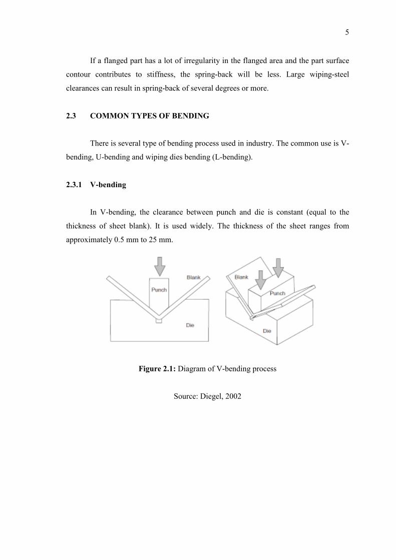
2.3.1 V-bending
In V-bending, the clearance between punch and die is constant (equal to the
thickness of sheet blank). It is used widely. The thickness of the sheet ranges from
approximately 0.5 mm to 25 mm.
Figure 2.1: Diagram of V-bending process
Source: Diegel, 2002

6
2.3.2 U-bending
U-bending is performed when two parallel bending axes are produced in the
same operation. A backing pad is used to force the sheet contacting with the punch
bottom. It requires about 30% of the bending force for the pad to press the sheet
contacting the punch.
Figure 2.2: Diagram of U-bending process
Source: Diegel, 2002
2.3.3 Wiping die bending (L-bending)
Wiping die bending is also known as flanging. One edge of the sheet is bent to
90º while the other end is restrained by the material itself and by the force of blank-
holder and pad. The flange length can be easily changed and the bend angle can be
controlled by the stroke position of the punch.

7
Figure 2.3: Diagram of L-Bending
Source: Diegel, 2002
2.4 BEND ALLOWANCE
When sheet metal is bent, the inside surface of the bend is compressed and the
outer surface of the bend is stretched. Somewhere within the thickness of the metal lies
its natural axis, which is a line in the metal that is neither compressed nor stretched.
What this means in practical terms is that if we want a work piece with a 90º
bend in which one leg measures A and other measures B, then the total length of the flat
piece is not A+B. to work out what length of the flat piece of metal needs to be, we need
to calculate the Bend Allowance or Bend Deduction that tells us how much we need to
add or subtracts to our leg length to get exactly what we want.

8
Figure 2.4: Bend allowance
Lt = A + B + BA (2.1)
Where:
Lt = total flat length
BA = bend allowance value
Figure 2.5: Bend deduction
Lt = A + B – BD (2.2)
Where:
Lt = total flat length
BD = bend deduction value

9
The location of the neutral line varies depending on the material itself, the radius
of the bend, the ambient temperature, direction on the material grain, and the method by
which it is being bent, etc. the location of this line is often referred to as the K-factor.
K-factor is a ratio that represents the location of the neutral sheet with respect to
the thickness of the sheet metal part.
Figure 2.6: Diagram of K-factor
Source: Diegel, 2002
The only truly effective way of working out the correct bend allowance is to
reverse engineer it by taking a measured strip of material, bending it and measuring it to
calculate the bend allowance. These bend allowance can be measured for many
materials and scenarios and then tabulated so that the table can be used by CAD
programs to produce accurate sheet metal work.
Many CAD programs however also work out bend allowances automatically by
using K-factor calculations.