Spray Nozzles Control Analysis Fabrication
12
Experts in Spray Technology A Division of Spray Nozzles Spray Control Spray Analysis Spray Fabrication Gas Cooling and Conditioning in Primary Metals A Guide to Improving Efficiency, Increasing Throughput, Reducing Downtime and Lowering Costs
Transcript of Spray Nozzles Control Analysis Fabrication

Experts in Spray Technology
A Division of
SprayNozzles
SprayControl
SprayAnalysis
SprayFabrication
Gas Cooling and Conditioning in Primary MetalsA Guide to Improving Efficiency, Increasing Throughput, Reducing Downtime and Lowering Costs
2
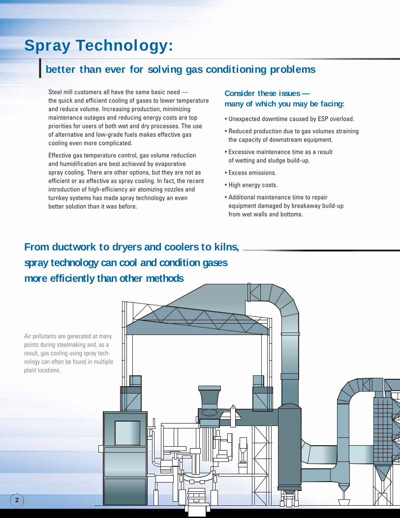
Steel mill customers all have the same basic need — the quick and efficient cooling of gases to lower temperatureand reduce volume. Increasing production, minimizing maintenance outages and reducing energy costs are top priorities for users of both wet and dry processes. The use of alternative and low-grade fuels makes effective gas cooling even more complicated.
Effective gas temperature control, gas volume reduction and humidification are best achieved by evaporative spray cooling. There are other options, but they are not asefficient or as effective as spray cooling. In fact, the recentintroduction of high-efficiency air atomizing nozzles andturnkey systems has made spray technology an even better solution than it was before.
• Unexpected downtime caused by ESP overload.
• Reduced production due to gas volumes straining the capacity of downstream equipment.
• Excessive maintenance time as a result of wetting and sludge build-up.
• Excess emissions.
• High energy costs.
• Additional maintenance time to repair equipment damaged by breakaway build-up from wet walls and bottoms.
Consider these issues — many of which you may be facing:
From ductwork to dryers and coolers to kilns,
spray technology can cool and condition gases more efficiently than other methods
Air pollutants are generated at manypoints during steelmaking and, as aresult, gas cooling using spray tech-nology can often be found in multipleplant locations.
Spray Technology: better than ever for solving gas conditioning problems
3
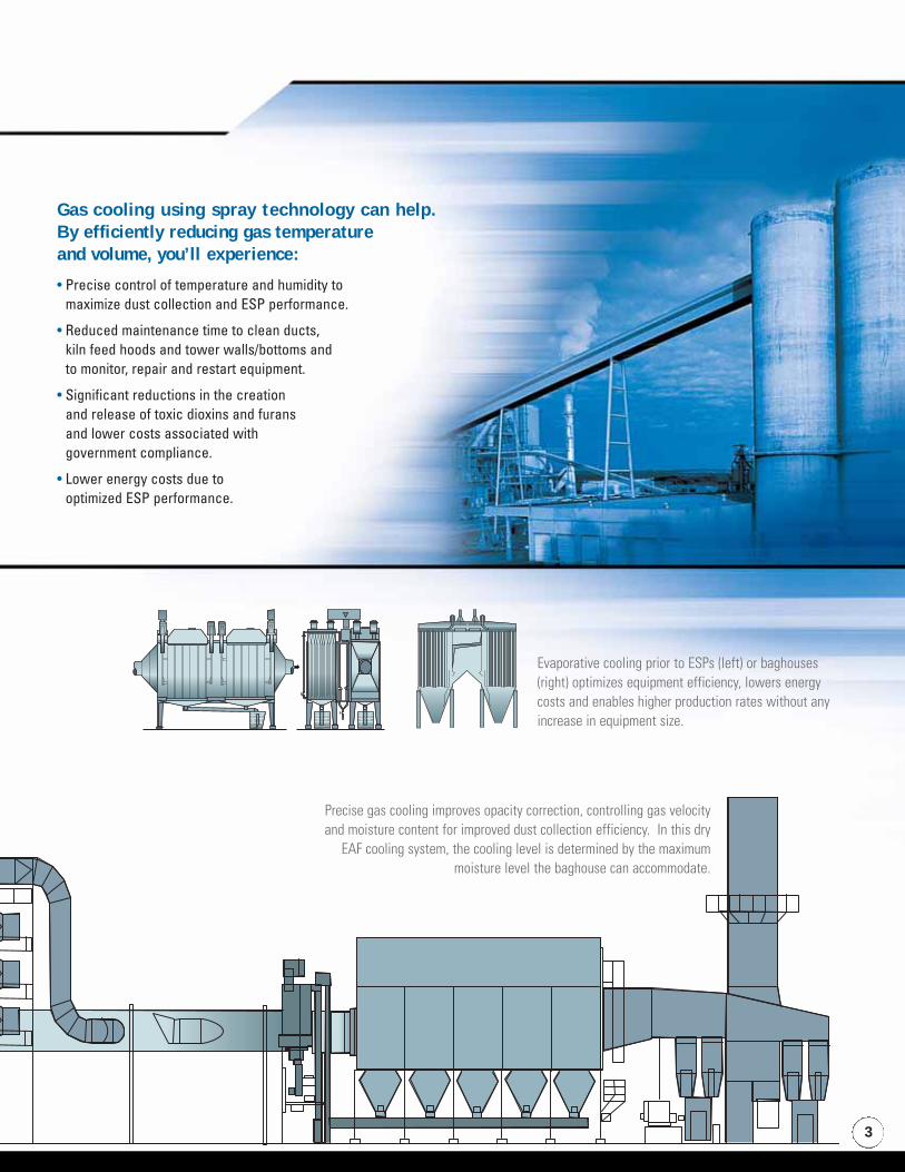
Gas cooling using spray technology can help. By efficiently reducing gas temperature and volume, you’ll experience:
• Precise control of temperature and humidity to maximize dust collection and ESP performance.
• Reduced maintenance time to clean ducts, kiln feed hoods and tower walls/bottoms and to monitor, repair and restart equipment.
• Significant reductions in the creation and release of toxic dioxins and furans and lower costs associated with government compliance.
• Lower energy costs due to optimized ESP performance.
Precise gas cooling improves opacity correction, controlling gas velocityand moisture content for improved dust collection efficiency. In this dry
EAF cooling system, the cooling level is determined by the maximummoisture level the baghouse can accommodate.
Evaporative cooling prior to ESPs (left) or baghouses(right) optimizes equipment efficiency, lowers energycosts and enables higher production rates without anyincrease in equipment size.
1. Optimal performance: Our AutoJet spray controller,with patent-pending SprayLogic® software, monitors andautomatically adjusts the closed loop system. Byregulating liquid and air flow to the nozzles based ondata gathered from RTD temperature sensors, thecontroller offers the highest level of reactivity andaccuracy for the system.
2. Plug and spray convenience: Pre-programmed withparameters and function screens specific to gasconditioning applications, our controller will save youtime and money during installation. Full LabVIEW®
simulation and system pre-testing prior to shippingensure full functionality upon set-up.
3. Total automation minimizes labor anddowntime: The AutoJet spray controller controls allsystem components — nozzles, pumps, sensors andother hydraulic/pneumatic components. If a problem isdetected that the controller can’t resolve automatically,operator warnings will be displayed or sounded.
4. Multiple lance zones: AutoJet GasConditioning Systems can be configured withmultiple lance zones to allow greater turndownof flow rate under variable system conditions.
5. Built for reliability: Emergency modes,system redundancy, intelligent fault sensing andpatent-pending continuous system integritychecking are just a few of the reasons why youcan count on long-term, trouble-freeperformance.
6. Reduced energy costs:Variable Frequency Drive (VFD)pumps provide proportionalliquid regulation and significantelectricity savings. In addition,energy-efficient proportional airregulation reduces air consump-tion and operating costs.
7. Easy integration: You can easily integrate the AutoJetGas Conditioning System with other systems throughdirect wiring and current splitters for access to criticaldata. For full control of all available data, an optional OPC communication link is available.
8. Ease of use: Our controller is easy to use and isequipped with complete spray “knowledge.” Just provideinformation about your operation using the menu systemand the controller will essentially configure itself.
9. Single source convenience: Should you have aquestion about your system, just give us a call. No needto contact multiple suppliers and coordinate their effortsshould a problem occur.
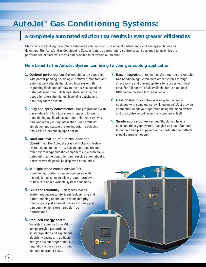
AutoJet® Gas Conditioning Systems:a completely automated solution that results in even greater efficiencies
Many mills are looking for a totally automated solution to ensure optimal performance and savings on labor anddowntime. Our AutoJet Gas Conditioning System features a proprietary control system designed to maximize theperformance of FloMax® nozzles and provides total system automation.
Nine benefits the AutoJet System can bring to your gas cooling application
4
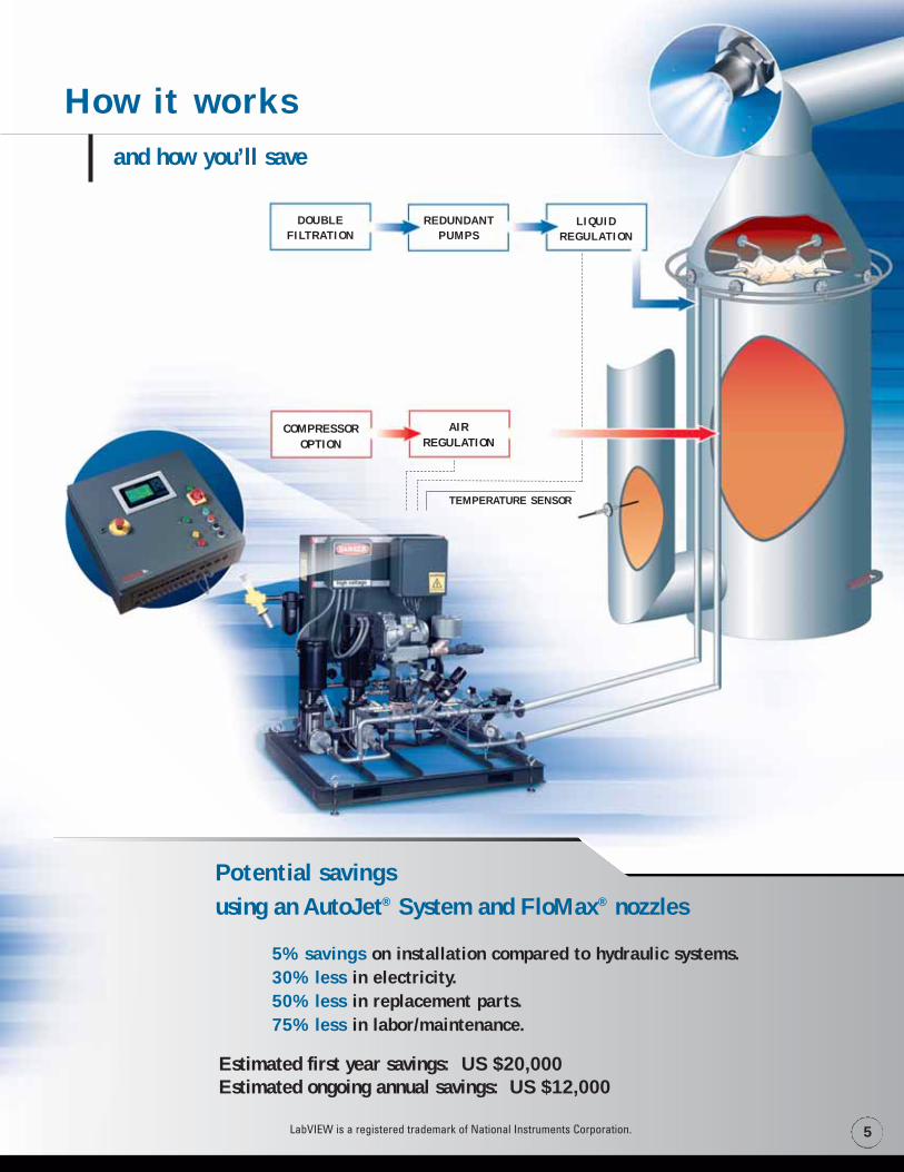
How it worksand how you’ll save
TEMPERATURE SENSOR
DOUBLEFILTRATION
LIQUIDREGULATION
REDUNDANTPUMPS
COMPRESSOROPTION
AIRREGULATION
5LabVIEW is a registered trademark of National Instruments Corporation.
5% savings on installation compared to hydraulic systems.30% less in electricity.50% less in replacement parts.75% less in labor/maintenance.
Estimated first year savings: US $20,000Estimated ongoing annual savings: US $12,000
Potential savings using an AutoJet® System and FloMax® nozzles

Drop size refers to the size of the individual spray drops that com-prise a nozzle's spray pattern. Each spray provides a range of dropsizes. This range is the drop size distribution.
Why it is important in gas conditioning
and what you need to knowDrop size is the critical consideration in evaporative cooling. Itimpacts virtually every aspect of gas cooling and can have a sig-nificant impact on cooling effectiveness.
Drop size data:
Sophisticated Spray Characterization and Testing Ensure Optimal Spray Performance
Determining the exact drop size required in gas coolingapplications is critical. Many problems result from premature orincomplete evaporation. If drops evaporate too quickly, thedesired level of absorption may not occur and upstream/downstream equipment may be less efficient or damaged. Ifdrops don’t evaporate quickly enough, wetting will occur,unplanned steam may result and dust can accumulate in the ductor tower and obstruct gas flow.
The most effective way to determine the required dwell time is toconduct spray characterization studies in a fully equipped spraylaboratory to simulate actual operating conditions.
Typically these studies include:
• Drop size testing to determine the optimal drop size anddrop size distribution.
• Determination of gas velocity and density and the resultingimpact on drop size.
Spray Analysis and Research Services, a service of Spraying Systems Co., is home to the most fully equipped spray laboratory in the world. We have several state-of-the-art instruments for drop size measurement including Phase Doppler Particle Analyzers, Laser Imaging, Particle/Image Analyzers and Laser Diffraction Analyzers.
Droplet Concentration
Low High
� Phase Doppler Particle AnalyzersThe Phase Doppler method is based on theprinciples of light scattering interferometry.These flux sampling instruments are mosteffective in measuring the drop size andvelocity of medium to large sprays.
In some cases, simulatingoperating conditions in a
laboratory environment andmodeling of the data is not
feasible. That’s when we turn toComputational Fluid Dynamics
(CFD) and proprietary dropdistribution calculations. These
tools enable us to accuratelypredict spray performance in a
customer’s operating environment.
6
μm – micrometers
�

7
Evaporative cooling can be achieved two ways: with hydraulic spray nozzles or air atomizing nozzles. Historically, high-pressure hydraulic nozzles have been used primarily because high-efficiency air atomizing nozzles weren’t available. However, significant technological advances in atomization have occurred in the last decade and air atomizing nozzles are now the preferred solution. The charts that follow explain why.
* Based on FloMax® nozzle spraying 10.0 gpm at 50 psig air pressure and the Flowback 7.0 gpm nozzle at 580 psig liquid pressure.
• Low-pressure pumps require little maintenance.
• Lack of wetting eliminates clean-up of sludge and build-up.
• Wear-resistant materials require less maintenance.
• High-pressure pumps require more maintenance.
• Wet walls and bottoms require considerable cleaning.
• Corrosion due to excess humidity possible.
• High-pressure atomization results in accelerated wear, higher replacement costs and performance problems.
Hydraulic vs. air atomizing:comparing the evaporative cooling options
• Precise control of both liquid and air. • Fluctuates with pressure changes.
• Small: 200 μm Dmax* reduces dwell time and risk of wetting.
• Large: 290 μm Dmax* (42% larger than a drop from an atomizing nozzle); more dwell time required, wetting more likely.
• Performance improves due to an increase in gas density and a reduction in volume/velocity.
• Performance improvements limited; may require expansion if volume increases.
• Low-pressure pumps require less energy.
• Compressors required but nozzles are air efficient.
• Faster cooling and more efficient reduction of gas volume requires less energy.
• High-pressure pumps are not energy efficient.
• No compressors required.
• Requires low-pressure pumps and low-pressure piping.
• High capacity nozzles mean fewer lances required.
• Smaller cooling tower.
• Requires high-pressure pumps and high-pressure piping.
• Lower capacity limits on nozzles required to ensure drops evaporate effectively.
• More nozzles mean more lances and larger cooling towers.
• River water, basins and run-off water acceptable due to nozzle large free passage.
• Clean water supply (drinking water standard or better)required to ensure nozzle clogging is minimized.
• Better temperature/humidity control enables reductions in toxic dioxins and furans and lowers cost of compliance.
• Particulate release more likely because of variations in drop size and less control over temperature/humidity.
OVERALL PERFORMANCE
DROP SIZE
PARTICULATECOLLECTION DEVICES
EMISSION CONTROL
ENERGY
EQUIPMENT COST
MAINTENANCE
WATER
P E R F O R M A N C E C O M PA R I S O N
AIR ATOMIZING NOZZLES HYDRAULIC NOZZLES

8
High-efficiency air atomizing nozzles result in more than energy and operational savings — smaller cooling towers are possible
20.6 ft. (6.3 m) 26.2 ft. (8.0 m)
39.3 ft. (12.0 m) 52.5 ft. (16.0 m)
6 10
59 psig (4.1 barg) 600 psig (41.4 barg)
10.5 gpm (39.7 l/min) 7.0 gpm (26.5 l/min)
50 psig (3.5 barg) —
57 scfm (98 Nm3/hr) —
3.5 seconds 7.6 seconds
Air atomizing tower
Air atomizing nozzles requirefewer lances and smallercooling towers.
DIAMETER
HEIGHT
NUMBER OF LANCES
LIQUID PRESSURE
LIQUID VOLUME PER LANCE
AIR PRESSURE
AIR VOLUME PER LANCE
DWELL TIME FOR EVAPORATION
OPERATIONAL
PARAMETERS
GAS VOLUME
250,734 acfm (426,000 Nm3/hr)
INLET GAS TEMPERATURE
514° F (268° C)
OUTLET GAS TEMPERATURE
302° F (150° C)
TOTAL LIQUID SPRAYED
63.4 gpm (240 l/min)
Hydraulic tower
A cooling tower for a hydraulic systemwill be 34% taller and 27% wider than
an air atomizing tower. Plus, it willrequire four additional lances.
SAMPLE AIR ATOMIZINGTOWER SAMPLE HYDRAULIC TOWERSPECIFICATIONS
Choosing an air atomizing system can have a significant impact on the design of the cooling towerrequired. Since air atomizing nozzles produce smaller drop sizes and require shorter dwell times for com-
plete evaporation, fewer lances are needed than in hydraulic systems. An air atomizing tower willalso be significantly smaller than a hydraulic tower, which is illustrated below.
If you have an existing cooling tower and decide to replace an existing hydraulic systemwith an air atomizing system, significant increases in gas volume and increased produc-
tion may be possible. Increases in production are not typically possible in hydraulicsystems without increasing the size of the tower to accommodate additional lances.
Sample tower comparison
9
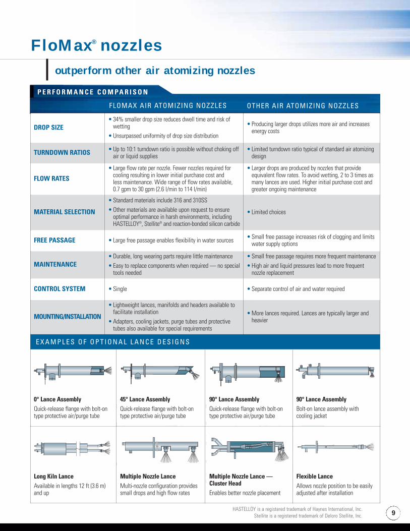
FloMax® nozzlesoutperform other air atomizing nozzles
TURNDOWN RATIOS
FLOW RATES
MATERIAL SELECTION
FREE PASSAGE
MAINTENANCE
CONTROL SYSTEM
MOUNTING/INSTALLATION
P E R F O R M A N C E C O M PA R I S O N
OTHER AIR ATOMIZING NOZZLESFLOMAX AIR ATOMIZING NOZZLES
E X A M P L E S O F O P T I O N A L L A N C E D E S I G N S
0˚ Lance AssemblyQuick-release flange withbolt-on type protectiveair/purge tube.
45˚ Lance AssemblyQuick-release flange withbolt-on type protectiveair/purge tube.
HASTELLOY is a registered trademark of Haynes International, Inc.Stellite is a registered trademark of Deloro Stellite, Inc.
DROP SIZE• 34% smaller drop size reduces dwell time and risk of
wetting• Unsurpassed uniformity of drop size distribution
• Producing larger drops utilizes more air and increasesenergy costs
TURNDOWN RATIOS • Up to 10:1 turndown ratio is possible without choking offair or liquid supplies
• Limited turndown ratio typical of standard air atomizingdesign
FLOW RATES
• Large flow rate per nozzle. Fewer nozzles required forcooling resulting in lower initial purchase cost and less maintenance. Wide range of flow rates available, 0.7 gpm to 30 gpm (2.6 l/min to 114 l/min)
• Larger drops are produced by nozzles that provideequivalent flow rates. To avoid wetting, 2 to 3 times asmany lances are used. Higher initial purchase cost andgreater ongoing maintenance
MATERIAL SELECTION
• Standard materials include 316 and 310SS• Other materials are available upon request to ensure
optimal performance in harsh environments, includingHASTELLOY®, Stellite® and reaction-bonded silicon carbide
• Limited choices
FREE PASSAGE • Large free passage enables flexibility in water sources • Small free passage increases risk of clogging and limitswater supply options
MAINTENANCE• Durable, long wearing parts require little maintenance• Easy to replace components when required — no special
tools needed
• Small free passage requires more frequent maintenance• High air and liquid pressures lead to more frequent
nozzle replacement
CONTROL SYSTEM • Single • Separate control of air and water required
MOUNTING/INSTALLATION
• Lightweight lances, manifolds and headers available tofacilitate installation
• Adapters, cooling jackets, purge tubes and protectivetubes also available for special requirements
• More lances required. Lances are typically larger andheavier
0° Lance AssemblyQuick-release flange with bolt-ontype protective air/purge tube
45° Lance AssemblyQuick-release flange with bolt-ontype protective air/purge tube
90° Lance AssemblyQuick-release flange with bolt-ontype protective air/purge tube
90° Lance AssemblyBolt-on lance assembly with cooling jacket
Long Kiln LanceAvailable in lengths 12 ft (3.6 m) and up
Multiple Nozzle LanceMulti-nozzle configuration providessmall drops and high flow rates
Multiple Nozzle Lance —Cluster HeadEnables better nozzle placement
Flexible LanceAllows nozzle position to be easilyadjusted after installation
P E R F O R M A N C E C O M PA R I S O N
FLOMAX AIR ATOMIZING NOZZLES OTHER AIR ATOMIZING NOZZLES
E X A M P L E S O F O P T I O N A L L A N C E D E S I G N S

34% Smaller drop size reduces dwell time for complete evaporation.
If you have a hydraulic system to maintain, ourFlowback nozzles may help improve performance
All air atomizing nozzles are not alike In fact, very few are suitable for use in gas conditioning. Highefficiency nozzles offer tight control of drop size and spray cover-age. The goal is to minimize Dmax and achieve a finely-atomizedspray with D32 less than 100 microns at 10 gpm (37.8 l/min). Amulti-stage atomization process must be used to achieve thisvery small drop size.
The patented three-stage atomization process used by FloMax air atomizing nozzles is extremely air efficient and is the primaryreason why it is the preferred nozzle for gas conditioning in steel mills.
Unlike competitive nozzles using single-step atomization, FloMaxnozzles produce a D32 drop size that is 34% smaller utilizing 20%less air than competitive nozzles. [Flow rate of 10 gpm (37.8 l/min)]Each nozzle uses as little as 45 scfm (76 Nm3/hr).
A closer look at high efficiency FloMax® air atomizing nozzles
NOZZLE TYPE CAPACITY (gpm) CAPACITY (l/min)FM5A 0.7 to 7.0 2.6 to 26.5FM10A 1.3 to 13.0 4.9 to 49.2FM25A 10.0 to 30.0 37.8 to 114
FloMax nozzles are available in a wide range of flow rates
Smaller drop size benefits:• Lower installation and maintenance costs due
to the wide range of flow rates per nozzle.
• The liquid being sprayed generates more surface area per gallon for a more complete reaction and total absorption without wetting.
• Lower energy costs.
• Longer compressor life due to lower air consumption.
10
Not every plant is in a position to undergo a technology upgrade. If you are maintaining a hydraulic system, our Flowback nozzles can help you improve performance.
Easily interchangeable with competitive products, these nozzles provide superiorperformance by delivering a consistent drop size. The system applies consistentpressure to the nozzle at all times. When the desired gas temperature is achievedand a reduction in volume is needed, a valve is adjusted to alter the amount of fluidleaving the nozzle. The excess fluid “flows back” through the center orifice of thenozzle body. The nozzle offers a 10:1 turndown ratioto accommodate variations ingas temperature or volume.
PF
FLOWBACK LINEFLOW RATE “D”
TOTAL FLOW
P1
11
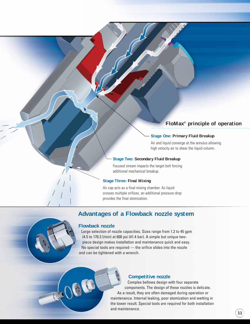
Stage Three: Final Mixing
Air cap acts as a final mixing chamber. As liquidcrosses multiple orifices, an additional pressure dropprovides the final atomization.
Stage Two: Secondary Fluid Breakup
Focused stream impacts the target bolt forcingadditional mechanical breakup.
Stage One: Primary Fluid Breakup
Air and liquid converge at the annulus allowinghigh velocity air to shear the liquid column.
FloMax® principle of operation
Competitive nozzleComplex bellows design with four separate
components. The design of these nozzles is delicate.As a result, they are often damaged during operation or
maintenance. Internal leaking, poor atomization and wetting inthe tower result. Special tools are required for both installationand maintenance.
Advantages of a Flowback nozzle system
Flowback nozzleLarge selection of nozzle capacities. Sizes range from 1.2 to 45 gpm(4.5 to 170.3 l/min) at 600 psi (41.4 bar). A simple but unique two-piece design makes installation and maintenance quick and easy.
No special tools are required — the orifice slides into the nozzleand can be tightened with a wrench.
Other resources:
FloMax® Air Atomizing NozzlesBulletin 487CFeatures details and performance data on the unmatched energy-efficient FloMax nozzles and lances.
Spray Technology Reference Guide: Understanding Drop SizeBulletin 459BAn invaluable technical guide. We’ve taken 60 years of spray drop knowledgeand condensed it into a 36-page booklet to teach you the fundamentals of evaluating and interpreting drop size data.
A Guide to Spray Technology for Steel MillsCatalog 44 and 44MDetailed information on our full range of products for steel manufacturing isincluded in this 92-page catalog.
A Guide to Optimizing Spray Injector PerformanceBulletin 579AAddresses the specification, design and fabrication of spray injectors/lances to ensure optimal nozzle performance.
Optimizing Your Spray System: Spray Nozzle Maintenance and Control for Improved Production EfficiencyTechnical Manual 410Explains how to maximize performance and quality in your spray application.
P.O. Box 7900Wheaton, IL 60189-7900 USATel: 1.800.95.SPRAYFax: 1.888.95.SPRAYE-mail: [email protected]
Outside the U.S. Tel: 1.630.665.5000Fax: 1.630.260.0842
www.spray.com
Represented by:
Bulletin 459B
Catalog 44
Bulletin No. 597 Printed in U.S.A. © Spraying Systems Co. 2006
Bulletin 579A
Bulletin 487C