Sponge-Jet Sponge Blasting System Sponge-Jet Continuous ... · IMPORTANT NOTE: While parts,...
15
Sponge-Jet CVR-P110 User Manual - 9 January 2013 ENGLISH Sponge-Jet ® Sponge Blasting System Sponge-Jet Continuous VAC- Recovery System User Manual Model CVR-P110 Headquarters/Manufactured By: Sponge-Jet, Inc. (USA) 14 Patterson Lane, Newington, NH 03801 1-603-610-7950 / www.spongejet.com ™ ™
Transcript of Sponge-Jet Sponge Blasting System Sponge-Jet Continuous ... · IMPORTANT NOTE: While parts,...
Sponge-Jet CVR-P110 User Manual - 9 January 2013 ENGLISH
Sponge-Jet® Sponge Blasting System
Sponge-Jet Continuous VAC-Recovery System
User Manual Model
CVR-P110
Headquarters/Manufactured By:
Sponge-Jet, Inc. (USA)
14 Patterson Lane, Newington, NH 03801 1-603-610-7950 / www.spongejet.com
™
™
Table of Contents
Section Page
1.0 Introduction 3
2.0 Safety Checklist 5
3.0 Assembly 6
4.0 Requirements 11
5.0 Operation 12
6.0 Troubleshooting 14
Notes 15
IMPORTANT NOTE: While parts, systems, components, operational procedures may be the same between equipment models, the images provided in this manual may vary from model to model.
This manual represents the following model: CVR-P110
English Language is Original Instructions.
Sponge-Jet CVR-P110 User Manual - 9 January 2013 Page 3 of 15
1.0 Introduction
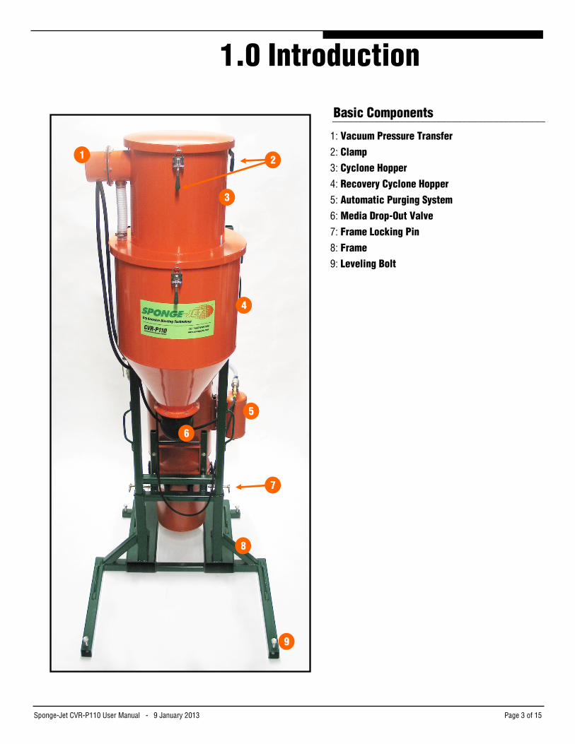
Basic Components _________________________________________
1: Vacuum Pressure Transfer 2: Clamp 3: Cyclone Hopper 4: Recovery Cyclone Hopper 5: Automatic Purging System 6: Media Drop-Out Valve 7: Frame Locking Pin 8: Frame 9: Leveling Bolt
3
1 2
4
8
6
5
7
9

Sponge-Jet CVR-P110 User Manual - 9 January 2013 Page 4 of 15
Basic Components (continued) ___________________________________________
10: Vacuum Hose Connection 11: Internal Vacuum Source Hose 12: Timer-Control Panel 13: Frame Handle 14: Vacuum Ejector 15: Main Air Ball Valve 16: Supply Line Connection 17: Vacuum Filter Silo 18: Vacuum Dust Bin 19: Vacuum Pressure Gauge 20: Differential Pressure Gauge 21: Frame Locking Pin 22. Recovery Cyclone Hopper Frame 23. Intermediate Extension Frame 24. Bottom Frame
10
12
14
11
15
18
13
17
16
19
20
21
22
23
24
Sponge-Jet CVR-P110 User Manual - 9 January 2013 Page 5 of 15
2.0 Safety Checklist
o This Unit is a pressurized system. Only trained operators should adjust, maintain and repair this equipment.
o Inbound pressure should never exceed 8bar (115psi) regardless of model.
o To prevent electrostatic buildup and possible electric discharge, the unit must be properly grounded / bonded.
o Operators and people in proximity to blasting should always wear eye and hearing protection with the appropriate respiratory equipment and clothing, which may depend on the type of coating or contaminant being removed.
o All pneumatic lines should be inspected for holes, wear and proper fit. o Safety pins and restraints should be fitted at all Supply Air Hose
couplings to prevent accidental disconnection.
o Verify the unit is stable, secure and on a flat surface.
o Before all activities (other than normal operation), ensure the entire system is depressurized.
o Never perform maintenance or repairs when the unit is pressurized. o Never operate the machine with any worn or malfunctioning component. o Do not move/transport with Sponge Media in unit or when Frame is fully
assembled. Moving unit while fully loaded or when Frame extends the Cyclone Hopper above 1.88m (74in) may result in property damage or serious injury.
IMPORTANT: Under NO circumstances should any inspection, adjustment or lubrication be conducted while running or connected to an air supply.
Sponge-Jet CVR-P110 User Manual - 9 January 2013 Page 6 of 15
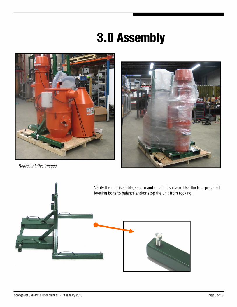
Verify the unit is stable, secure and on a flat surface. Use the four provided leveling bolts to balance and/or stop the unit from rocking.
™
Representative images
3.0 Assembly
Sponge-Jet CVR-P110 User Manual - 9 January 2013 Page 7 of 15
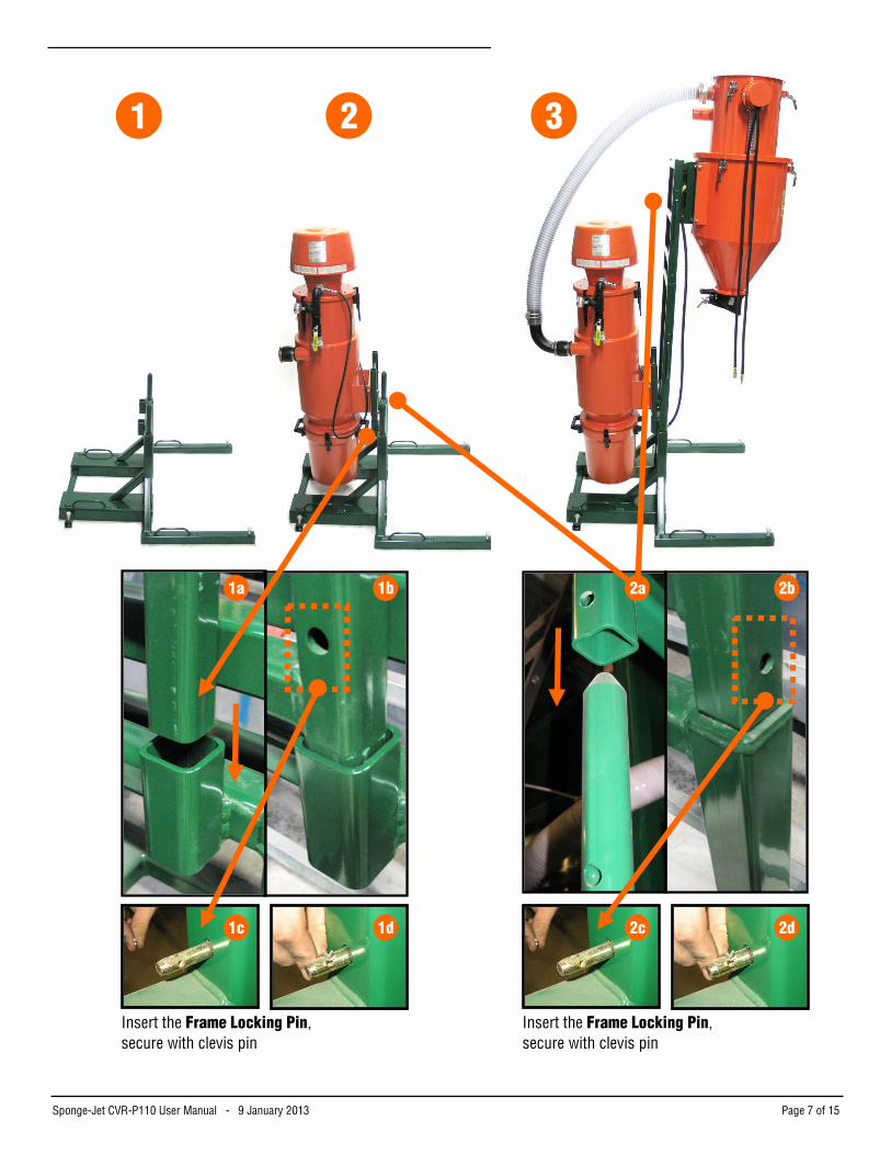
Insert the Frame Locking Pin, secure with clevis pin
1c 1d 2c 2d
Insert the Frame Locking Pin, secure with clevis pin
1 2 3
1a 1b 2b 2a

Sponge-Jet CVR-P110 User Manual - 9 January 2013 Page 8 of 15
Check all Clamps are engaged
1 2
3 4
4 5 6
NOTE: This clamp style may also have been used.
Sponge-Jet CVR-P110 User Manual - 9 January 2013 Page 9 of 15
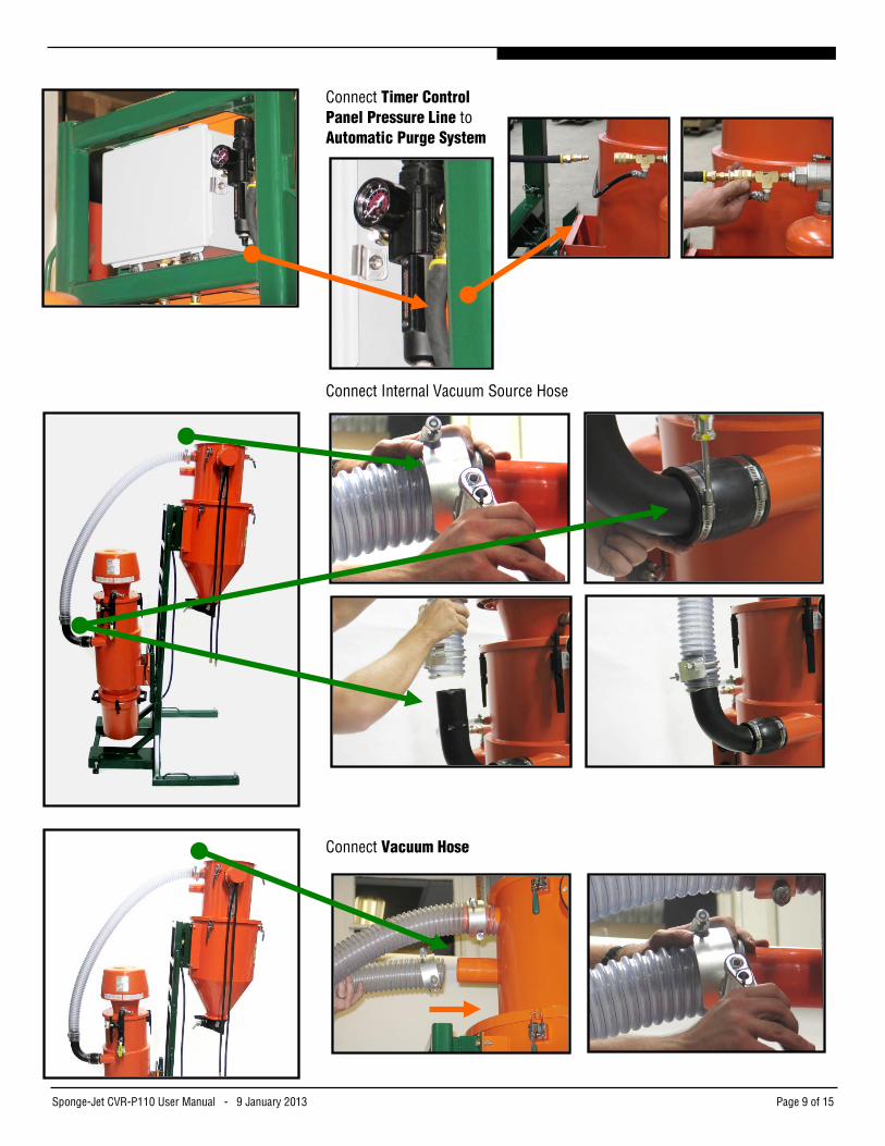
Connect Timer Control Panel Pressure Line to Automatic Purge System
Connect Internal Vacuum Source Hose
Connect Vacuum Hose
Sponge-Jet CVR-P110 User Manual - 9 January 2013 Page 10 of 15
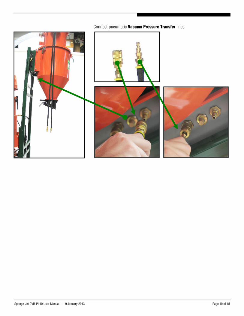
Connect pneumatic Vacuum Pressure Transfer lines
Sponge-Jet CVR-P110 User Manual - 9 January 2013 Page 11 of 15
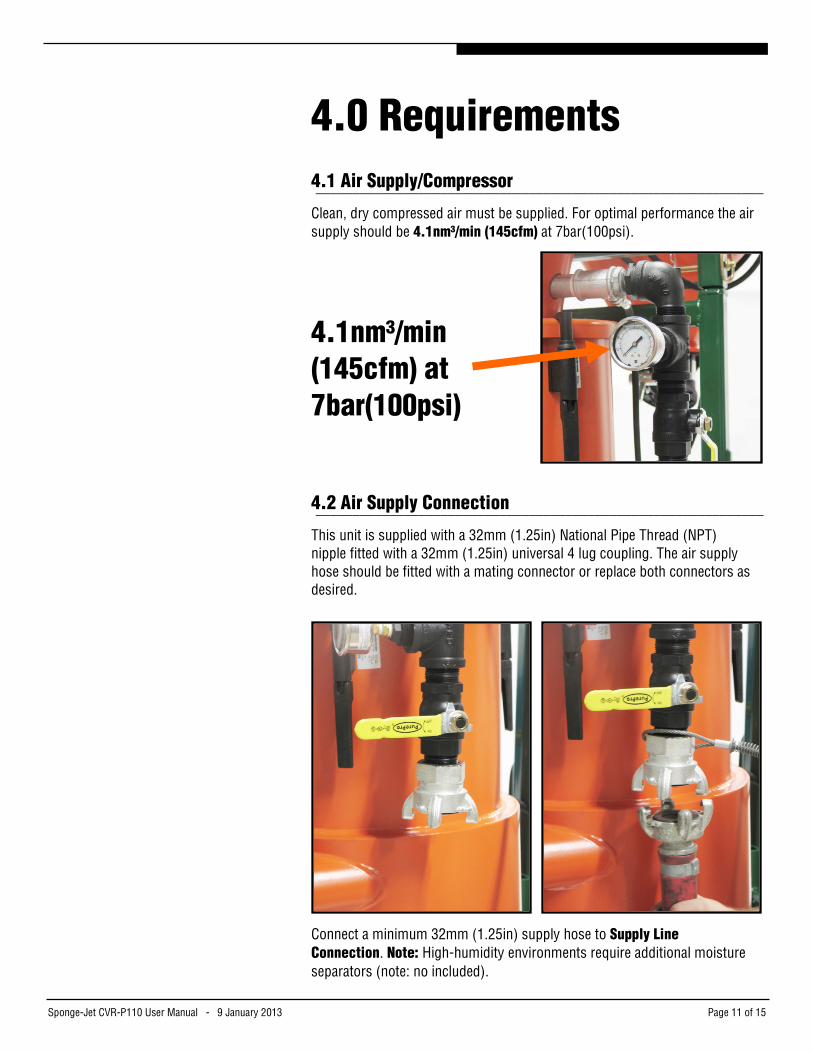
4.0 Requirements 4.1 Air Supply/Compressor _____________________________________________________________
Clean, dry compressed air must be supplied. For optimal performance the air supply should be 4.1nm³/min (145cfm) at 7bar(100psi).
4.1nm³/min (145cfm) at
7bar(100psi)
4.2 Air Supply Connection _____________________________________________________________
This unit is supplied with a 32mm (1.25in) National Pipe Thread (NPT) nipple fitted with a 32mm (1.25in) universal 4 lug coupling. The air supply hose should be fitted with a mating connector or replace both connectors as desired.
Connect a minimum 32mm (1.25in) supply hose to Supply Line Connection. Note: High-humidity environments require additional moisture separators (note: no included).
Sponge-Jet CVR-P110 User Manual - 9 January 2013 Page 12 of 15
5.0 Operation
Before Pressurization and Operation: o Verify the unit is stable, secure and on a flat surface. o All pneumatic lines should be inspected for holes, wear and proper fit. o Safety pins and restraints should be fitted at all Supply Air Hose
couplings to prevent accidental disconnection. o Before all activities (other than normal operation), ensure the entire
system is depressurized.
o Do not move/transport with Sponge Media in unit or when Frame is fully assembled. Moving unit while fully loaded or when Frame extends the Cyclone Hopper above 1.88m (74in) may result in property damage or serious injury.
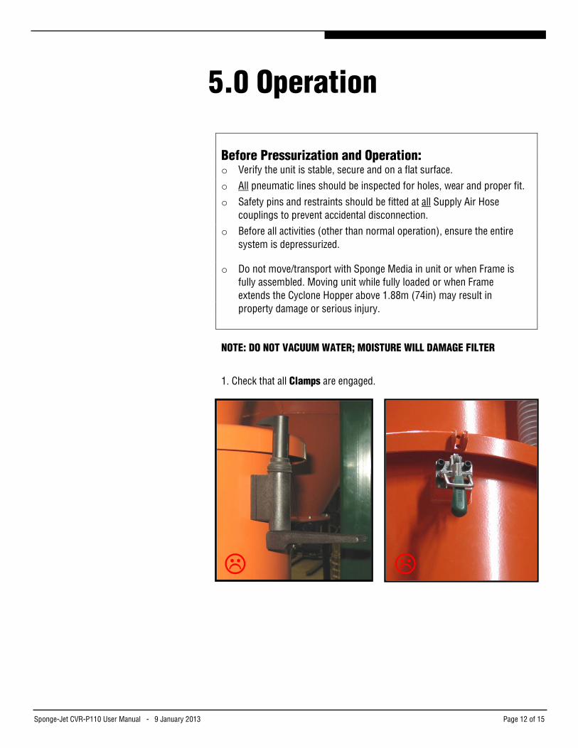
NOTE: DO NOT VACUUM WATER; MOISTURE WILL DAMAGE FILTER
1. Check that all Clamps are engaged.
Sponge-Jet CVR-P110 User Manual - 9 January 2013 Page 13 of 15
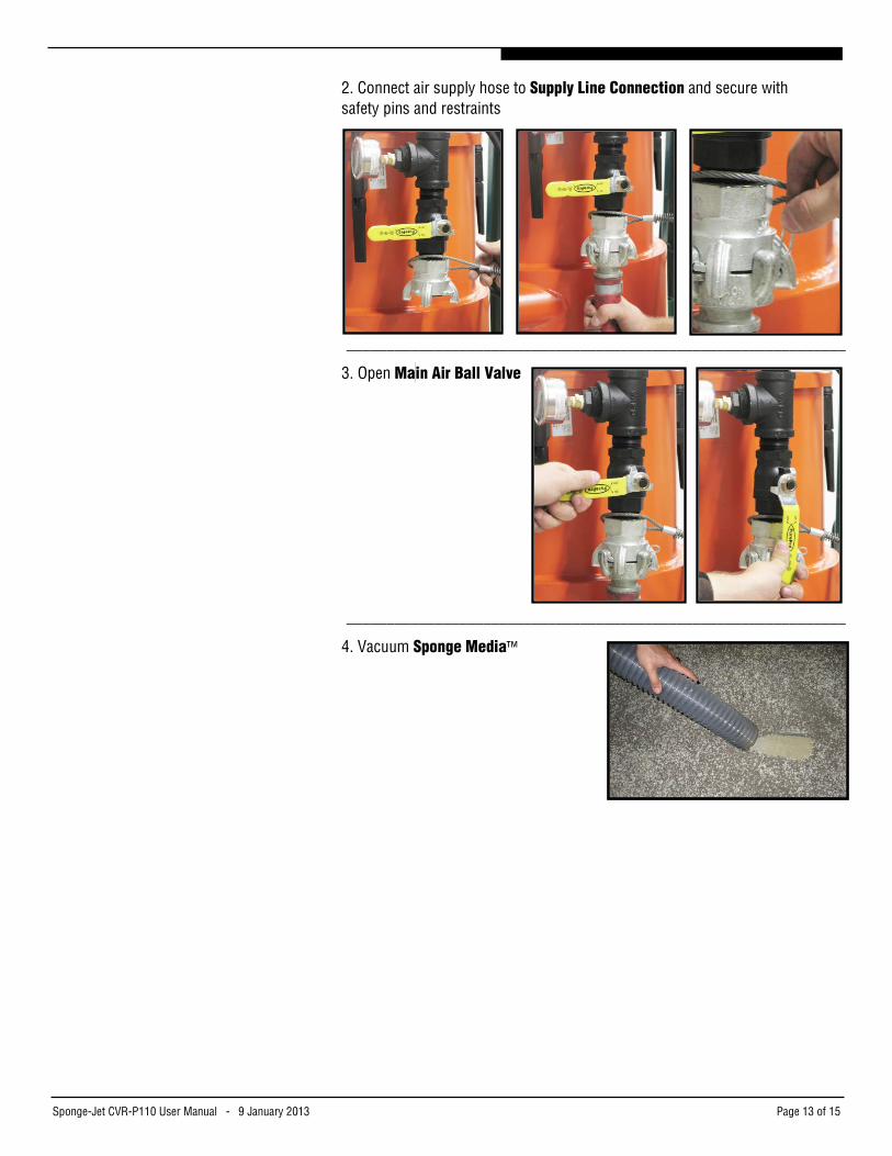
2. Connect air supply hose to Supply Line Connection and secure with safety pins and restraints
______________________________________________________________
3. Open Ma in Air Ball Valve
______________________________________________________________
4. Vacuum Sponge Media™

Sponge-Jet CVR-P110 User Manual - 9 January 2013 Page 14 of 15
6.0 Troubleshooting
Unit won't turn on Ensure air supply is maintaining an average of 7bar(100psi). Note: pressures higher than recommended can reduce vacuum performance.
Unit won't vacuum Check for obstructions in Vacuum Hose and remove. Check filter: 1. Remove excessive dust or debris 2. Inspect for physical damage 3. Inspect for moisture damage Replace if necessary
Reduced Vacuum Pressure; Vacuum Pressure is weak
Check Differential Pressure gauge does not read above 0.2Bar. If Differential Pressure gauge does read above 0.2Bar, clean and/or replace filter.
>0.2bar
Sponge-Jet CVR-P110 User Manual - 9 January 2013 Page 15 of 15
NOTES: _______________________________________________________
_____________________________________________________________
_____________________________________________________________
_____________________________________________________________
_____________________________________________________________
_____________________________________________________________
_____________________________________________________________
_____________________________________________________________
_____________________________________________________________
_____________________________________________________________
_____________________________________________________________
_____________________________________________________________
_____________________________________________________________
_____________________________________________________________
_____________________________________________________________
_____________________________________________________________
_____________________________________________________________
_____________________________________________________________
_____________________________________________________________
MODEL#: ______________________________________________________
SERIAL#: ______________________________________________________