SPNU553 | TI.com - Semiconductor company | TI.com
103
Safety Manual for RM42x and RM41x Hercules™ ARM ® -Based Safety Critical Microcontrollers User's Guide Literature Number: SPNU553B November 2014 – Revised October 2015
Transcript of SPNU553 | TI.com - Semiconductor company | TI.com

Safety Manual for RM42x and RM41xHercules™ ARM®-Based Safety CriticalMicrocontrollers
User's Guide
Literature Number: SPNU553BNovember 2014–Revised October 2015

Contents
1 Introduction ........................................................................................................................ 72 Hercules RM42x and RM41x Product Overview........................................................................ 9
2.1 Targeted Applications .................................................................................................. 102.2 Product Safety Constraints ............................................................................................ 10
3 Hercules Development Process for Management of Systematic Faults ..................................... 113.1 TI Standard MCU Automotive Development Process ............................................................. 123.2 TI MCU Automotive Legacy IEC 61508 Development Process .................................................. 133.3 Yogitech fRMethodology Development Process ................................................................... 133.4 Hercules Enhanced Safety Development Process ................................................................. 13
4 Hercules Product Architecture for Management of Random Faults........................................... 154.1 Safe Island Philosophy and Architecture Partition to Support Safety Analysis (FMEA/FMEDA) ............ 154.2 Identification of Parts/Elements ....................................................................................... 174.3 Management of Family Variants ...................................................................................... 184.4 Operating States ........................................................................................................ 184.5 Management of Errors ................................................................................................. 19
5 System Integrator Recommendations ................................................................................... 205.1 System Integrator Activities ........................................................................................... 205.2 Hints for Performing Dependent/Common Cause Failure Analysis Including the Hercules MCU ........... 225.3 Hints for Improving Independence of Function/Co-Existence of Function When Using the Hercules MCU 225.4 Support for System Integrator Activities ............................................................................. 23
6 Brief Description of Elements .............................................................................................. 246.1 Power Supply ........................................................................................................... 246.2 Clocks .................................................................................................................... 246.3 Reset ..................................................................................................................... 256.4 System Control Module ................................................................................................ 256.5 Error Signaling Module (ESM) ....................................................................................... 266.6 CPU Subsystem ........................................................................................................ 266.7 Primary Embedded Flash ............................................................................................. 286.8 Flash EEPROM Emulation (FEE) .................................................................................... 296.9 Primary Embedded SRAM ............................................................................................ 306.10 Level 2 and Level 3 (L2 and L3) Interconnect Subsystem ........................................................ 316.11 EFuse Static Configuration ............................................................................................ 326.12 OTP Static Configuration .............................................................................................. 326.13 I/O Multiplexing Module (IOMM)...................................................................................... 336.14 Vectored Interrupt Module (VIM) ..................................................................................... 336.15 Real Time Interrupt (RTI) .............................................................................................. 346.16 High-End Timer (N2HET), HET Transfer Unit (HTU) .............................................................. 356.17 Multi-Buffered Analog-to-Digital Converter (MibADC) ............................................................. 366.18 Enhanced Quadrature Encoder Pulse (eQEP) ..................................................................... 376.19 Multi Buffered Serial Peripheral Interface (MibSPI) ................................................................ 376.20 Serial Peripheral Interface (SPI) ...................................................................................... 38
2 Table of Contents SPNU553B–November 2014–Revised October 2015Submit Documentation Feedback
Copyright © 2014–2015, Texas Instruments Incorporated

www.ti.com
6.21 Local Interconnect Network (LIN)..................................................................................... 396.22 Controller Area Network (DCAN) ..................................................................................... 396.23 General-Purpose Input/Output (GIO) ................................................................................ 406.24 JTAG Debug and Test Access........................................................................................ 416.25 Cortex-R4 Central Processing Unit (CPU) Debug.................................................................. 41
7 Brief Description of Diagnostics........................................................................................... 427.1 1oo2 Software Voting Using Secondary Free Running Counter ................................................. 427.2 Bit Error Detection ...................................................................................................... 427.3 Bit Multiplexing in FEE Memory Array ............................................................................... 427.4 Bit Multiplexing in Flash Memory Array .............................................................................. 427.5 Bit Multiplexing in Primary SRAM Memory Array................................................................... 427.6 Bit Multiplexing in Peripheral SRAM Memory Array................................................................ 427.7 CPU Illegal Operation and Instruction Trapping ................................................................... 437.8 CPU Logic Built In Self Test (LBIST) ................................................................................ 437.9 CPU Logic Built In Self Test (LBIST) Auto-Coverage.............................................................. 437.10 CPU Lockstep Compare .............................................................................................. 447.11 CPU Lockstep Comparator Self Test ................................................................................ 447.12 CPU Online Profiling Using the Performance Monitoring Unit.................................................... 447.13 CPU Memory Protection Unit (MPU)................................................................................. 447.14 CRC Auto-coverage .................................................................................................... 457.15 CRC in Message........................................................................................................ 457.16 DCAN Acknowledge Error Detection................................................................................. 457.17 DCAN Form Error Detection .......................................................................................... 457.18 DCAN Stuff Error Detection ........................................................................................... 457.19 DCAN Protocol CRC in Message..................................................................................... 457.20 Dual Clock Comparator (DCC)........................................................................................ 457.21 Efuse Autoload Self Test .............................................................................................. 467.22 Efuse Autoload Self Test Auto-Coverage ........................................................................... 467.23 EFuse ECC .............................................................................................................. 467.24 EFuse ECC Logic Self Test ........................................................................................... 467.25 eQEP Quadrature Watchdog.......................................................................................... 467.26 eQEP Software Test of Quadrature Watchdog Functionality ..................................................... 467.27 Error Trapping - IOMM ................................................................................................. 467.28 Error Trapping (including Peripheral Slave Error Trapping) - L2/L3 Interconnect.............................. 467.29 External Monitoring of Warm Reset (nRST) ........................................................................ 477.30 External Monitoring via ECLK......................................................................................... 477.31 External Voltage Supervisor........................................................................................... 477.32 External Watchdog ..................................................................................................... 477.33 FEE Contents Check by Hardware CRC ............................................................................ 477.34 FEE Data ECC .......................................................................................................... 477.35 FEE Sector Protection ................................................................................................. 487.36 Flash ATCM Address and Control Bus Parity ...................................................................... 487.37 Flash Contents Check by Hardware CRC........................................................................... 487.38 Flash ECC ............................................................................................................... 487.39 Flash Hard Error Cache and Livelock................................................................................ 497.40 Flash Sector Protection ................................................................................................ 497.41 Flash Wrapper Address ECC ......................................................................................... 497.42 Flash Wrapper Diag Mode 1 Test .................................................................................... 497.43 Flash Wrapper Diag Mode 2 Test .................................................................................... 49
3SPNU553B–November 2014–Revised October 2015 ContentsSubmit Documentation Feedback
Copyright © 2014–2015, Texas Instruments Incorporated

www.ti.com
7.44 Flash Wrapper Diag Mode 3 Test .................................................................................... 497.45 Flash Wrapper Diag Mode 4 Test .................................................................................... 497.46 Flash Wrapper Diag Mode 5 Test .................................................................................... 507.47 Flash Wrapper Diag Mode 7 Test .................................................................................... 507.48 Glitch Filtering on nRST and nPORRST ............................................................................ 507.49 Hardware CRC Check of OTP Contents ............................................................................ 507.50 Hardware Disable of JTAG Port ...................................................................................... 507.51 Information Redundancy Techniques ................................................................................ 507.52 Information Redundancy Techniques - L2/L3 Interconnect Specific............................................. 507.53 Information Redundancy Techniques - DCAN Specific............................................................ 507.54 Information Redundancy Techniques - N2HET Specific .......................................................... 517.55 Internal Voltage Monitor (VMON) .................................................................................... 517.56 Internal Watchdog ...................................................................................................... 517.57 IOMM Master ID Filtering .............................................................................................. 527.58 LIN Checksum Error Detection ....................................................................................... 527.59 LIN No-Response Error Detection.................................................................................... 527.60 LIN Physical Bus Error Detection..................................................................................... 527.61 LIN / SCI Bit Error Detection .......................................................................................... 527.62 LIN / SCI Frame Error Detection ..................................................................................... 527.63 LIN / SCI Overrun Error Detection.................................................................................... 527.64 Locking Mechanism for Control Registers........................................................................... 527.65 Lockout of JTAG Access Using AJSM............................................................................... 527.66 Low Power Oscillator Clock Detector (LPOCLKDET).............................................................. 537.67 Memory Protection Unit (MPU) for Non-CPU Bus Masters ...................................................... 537.68 Memory Protection Unit (MPU) for Cortex R4 CPU................................................................ 537.69 MibADC Converter Calibration........................................................................................ 537.70 MibADC Information Redundancy Techniques ..................................................................... 537.71 MibADC Input Self Test ................................................................................................ 537.72 MibSPI/SPI Data Length Error Detection............................................................................ 547.73 MibSPI/SPI Data Overrun Detection ................................................................................. 547.74 MibSPI/SPI Slave Desync Detection ................................................................................. 547.75 MibSPI/SPI Slave Timeout Detection ................................................................................ 547.76 Non-Privileged Bus Master Access .................................................................................. 547.77 OTP Autoload ECC..................................................................................................... 547.78 Parity in Message....................................................................................................... 547.79 Periodic Hardware CRC Check of OTP Contents.................................................................. 557.80 Periodic Software Test of VIM Functionality Including Error Tests .............................................. 557.81 Peripheral Central Resource (PCR) Access Management........................................................ 557.82 Periodic Hardware CRC Check of SRAM Contents................................................................ 557.83 Periodic Software Read Back of Static Configuration Registers ................................................ 557.84 Peripheral SRAM Parity................................................................................................ 557.85 PLL Slip Detector ....................................................................................................... 557.86 Primary SRAM BTCM Address and Control Bus Parity ........................................................... 567.87 Primary SRAM Data and ECC Storage in Multiple Physical Banks per Logical Address..................... 567.88 Primary SRAM Correctable ECC Profiling .......................................................................... 567.89 Primary SRAM Data ECC ............................................................................................. 567.90 Primary SRAM Wrapper Redundant Address Decode ............................................................ 577.91 Primary SRAM Hard Error Cache and Livelock .................................................................... 57
4 Contents SPNU553B–November 2014–Revised October 2015Submit Documentation Feedback
Copyright © 2014–2015, Texas Instruments Incorporated

www.ti.com
7.92 Privileged Mode Access and Multi-Bit Enable Keys for Control Registers...................................... 577.93 PBIST Check of Primary or Module SRAM ......................................................................... 587.94 PBIST Auto-coverage .................................................................................................. 587.95 PBIST Test of Parity Bit Memory ..................................................................................... 587.96 Redundant Address Decode Self Test............................................................................... 587.97 Shadow Registers ...................................................................................................... 587.98 Software Check of Cause of Last Reset ............................................................................ 597.99 Software Read Back of CPU Registers.............................................................................. 597.100 Software Read Back of Written Configuration ...................................................................... 597.101 Software Test of DCC Functionality ................................................................................. 597.102 Software Test of DWD Functionality ................................................................................. 597.103 Software Test of DWWD Functionality .............................................................................. 597.104 Software Test of ECC Profiler ........................................................................................ 597.105 Software Test of Error Path Reporting .............................................................................. 597.106 Software Test of Flash Sector Protection Logic .................................................................... 597.107 Software Test of Function Including Error Tests ................................................................... 597.108 Software Test of Function Using I/O Loopback .................................................................... 607.109 Software Test of Function Using I/O Checking In GIO Mode .................................................... 607.110 Software Test of Function Using I/O Loopback in Transceiver / PHY .......................................... 607.111 Software Test of Function Using I/O Loopback - IOMM Only .................................................... 607.112 Software Test of Hardware CRC ..................................................................................... 607.113 Software Test of MPU Functionality ................................................................................. 607.114 Software Test of Parity Logic ......................................................................................... 607.115 Software Test of PBIST ............................................................................................... 617.116 Software Test of SRAM Wrapper Address Decode Diagnostic and ECC ...................................... 617.117 Software Test for Reset ............................................................................................... 617.118 Software Warm Reset Generation ................................................................................... 617.119 Transmission Redundancy ............................................................................................ 617.120 Use of CoreSight Debug Logic Key Enable Scheme.............................................................. 617.121 Use of DCC as Program Sequence Watchdog..................................................................... 617.122 Use of MPUs to Block Access to Memory Mapped Debug ....................................................... 61
8 Next Steps in Your Safety Development ................................................................................ 61Appendix A Summary of Recommended Safety Feature Usage........................................................ 63Appendix B Development Interface Agreement .............................................................................. 96
B.1 Appointment of Safety Managers ................................................................................... 96B.2 Tailoring of the Safety Lifecycle ..................................................................................... 96B.3 Activities Performed by TI ............................................................................................ 98B.4 Information to be Exchanged ........................................................................................ 98B.5 Parties Responsible for Safety Activities ........................................................................... 99B.6 Communication of Target Values ................................................................................... 99B.7 Supporting Processes and Tools .................................................................................. 100B.8 Supplier Hazard and Risk Assessment ........................................................................... 100B.9 Creation of Functional Safety Concept ........................................................................... 100
Appendix C Revision History ..................................................................................................... 101
5SPNU553B–November 2014–Revised October 2015 ContentsSubmit Documentation Feedback
Copyright © 2014–2015, Texas Instruments Incorporated

www.ti.com
List of Figures1 Device Revision Code Identification....................................................................................... 72 Hercules Product Architecture Overview ................................................................................. 93 TI Standard MCU Automotive QM Development Process ............................................................ 124 Hercules Enhanced Functional Safety Development Process ....................................................... 145 Partition of Hercules MCU for Safety Analysis ......................................................................... 166 Operating States of the Hercules MCU ................................................................................. 187 Diverse CPU Physical Orientation ....................................................................................... 278 Lockstep Temporal Diversity.............................................................................................. 289 Block Level Implementation of CPU SRAM ............................................................................ 5610 Hercules Tailoring of Safety Lifecycle ................................................................................... 97
List of Tables1 Identification of Parts/Elements .......................................................................................... 172 Summary of ESM Error Indication ....................................................................................... 193 Key to Summary of Safety Features and Diagnostics................................................................. 634 Summary of Safety Features and Diagnostics ........................................................................ 645 Activities Performed by TI vs. Performed by SEooC Customer...................................................... 986 Product Safety Documentation ........................................................................................... 997 Product Functional Documentation to be Considered in Safety-Related Design .................................. 998 Product Safety Documentation Tools and Formats .................................................................. 1009 SPNU553B Revisions .................................................................................................... 101
6 List of Figures SPNU553B–November 2014–Revised October 2015Submit Documentation Feedback
Copyright © 2014–2015, Texas Instruments Incorporated

432xPZT
###-#######
RM42L
Device Revision Code
User's GuideSPNU553B–November 2014–Revised October 2015
Safety Manual for RM42x and RM41x Hercules™ ARM®-Based Safety Critical Microcontrollers
1 IntroductionYou, a system and equipment manufacturer or designer, are responsible to ensure that your systems (andany TI hardware or software components incorporated in your systems) meet all applicable safety,regulatory, and system-level performance requirements. All application and safety related information inthis document (including application descriptions, suggested safety measures, suggested TI products, andother materials) is provided for reference only. You understand and agree that your use of TI componentsin safety critical applications is entirely at your risk, and that you (as buyer) agree to defend, indemnify,and hold harmless TI from any and all damages, claims, suits, or expense resulting from such use.
This document is a safety manual for the Texas Instruments Hercules safety critical microcontrollerproduct family. The product family utilizes a common safety architecture that is implemented in multipleapplication focused products. Product configurations supported by this safety manual include siliconrevisions 0, A and B of the following products: (Note that the part numbers listed below are for revision B;other revisions are slightly different. The device revision can be determined by the symbols marked on thetop of the device as seen in Figure 1 below this list).• RM4xx Safety Critical Microcontrollers
– RM41L232 (Orderable Part #: RM41L232BPZT)– RM41L232 (Orderable Part #: RM41L232BPZTR)– RM42L432 (Orderable Part #: RM42L432BPZT)– RM42L432 (Orderable Part #: RM42L432BPZTR)
Figure 1. Device Revision Code Identification
This Safety Manual provides information needed by system developers to assist in the creation of a safetycritical system using a supported Hercules microcontroller. This document contains:• An overview of the superset product architecture• An overview of the development process utilized to reduce systematic failures
Hercules, SafeTI are trademarks of Texas Instruments.ARM, Cortex are registered trademarks of ARM Limited.Adobe is a trademark of Adobe Systems Incorporated in the United States, and/or other countries.IBM, DOORS are registered trademarks of International Business Machines Corporation, registered in many jurisdictions worldwide.Microsoft, Excel are registered trademarks of Microsoft Corporation in the United States and/or other countries, or both.All other trademarks are the property of their respective owners.
7SPNU553B–November 2014–Revised October 2015 Safety Manual for RM42x and RM41x Hercules™ ARM®-Based SafetyCritical MicrocontrollersSubmit Documentation Feedback
Copyright © 2014–2015, Texas Instruments Incorporated

Introduction www.ti.com
• An overview of the safety architecture for management of random failures• The details of architecture partitions, implemented safety mechanisms
The following information is documented in the Safety Analysis Report Summary for RM42x and RM41xARM®-Based Safety Critical Microcontrollers (SPNU557) and is not repeated in this document:• Summary of failure rates of the MCU estimated at the chip level• Assumptions of use utilized in calculation of safety metrics• Summary of targeted standard (IEC 61508, ISO 26262, and so forth) safety metrics at the chip level
The following information is documented in the Detailed Safety Analysis Report for RM42x and RM41xARM®-Based Safety Critical Microcontrollers (SPNU560) and is not repeated in this document:• Fault model used to estimate device failure rates suitable to enable calculation of customized failure
rates• Quantitative FMEA (also known as FMEDA, Failure Modes, Effects, and Diagnostics Analysis) with
detail to the sub-module level of the device, suitable to enable calculation based on customizedapplication of diagnostics
The following information is documented in the Safety Report, and will not be repeated in this document:• Results of assessments of compliance to targeted standards
The user of this document should have a general familiarity with the Hercules product families. For moreinformation, see http://www.ti.com/hercules. This document is intended to be used in conjunction with thepertinent data sheets, technical reference manuals, and other documentation for the products underdevelopment.
For information which is beyond the scope of the listed deliverables, please contact your TI salesrepresentative or http://www.ti.com.
8 Safety Manual for RM42x and RM41x Hercules™ ARM®-Based Safety SPNU553B–November 2014–Revised October 2015Critical Microcontrollers Submit Documentation Feedback
Copyright © 2014–2015, Texas Instruments Incorporated

Level Two Hierarchy
Level Three Hierarchy
Level One Hierarchy
Cortex R4F CPU
SRAM
SRAM
Flash
64b B1TCM
64b B0TCM
64b ATCM
Cortex R4 CPU
Cluster
Switched Central Resource
Bus Master
Peripheral
Bus Master
Peripheral
Debug Bus
Master
64b
level two
CPU master
64b
Level two
CPU slave
Flash
Emulated
EEPROM
Peri
ph
era
lC
en
tralR
eso
urc
e
Peripheral
Peripheral
Peripheral
Peripheral
Peripheral
Peripheral
Bus Master
Peripheral
Peri
ph
era
lC
en
tralR
eso
urc
e
Peripheral
Peripheral
Peripheral
Peripheral
Peripheral
Peripheral
www.ti.com Hercules RM42x and RM41x Product Overview
2 Hercules RM42x and RM41x Product OverviewThe 65 nm Hercules product family is an evolution of the proven TMS570LS 130 nm safety MCU familyinto a 65 nm manufacturing process. A simplified graphical view of the product superset architecture canbe seen in Figure 2. This is a basic representation of the architecture and is not all inclusive. For example,products in the family may scale based on the number of peripherals, number of bus master peripherals,or amount of memory - but the programmer's model remains consistent.
Figure 2. Hercules Product Architecture Overview
9SPNU553B–November 2014–Revised October 2015 Safety Manual for RM42x and RM41x Hercules™ ARM®-Based SafetyCritical MicrocontrollersSubmit Documentation Feedback
Copyright © 2014–2015, Texas Instruments Incorporated

Hercules RM42x and RM41x Product Overview www.ti.com
The Hercules product architecture utilizes the proven ARM Cortex®-R4 CPU in a tightly coupled memoryconfiguration. The Cortex-R4 CPU is implemented with a checker Cortex-R4 CPU in a lockstepconfiguration. This provides cycle by cycle checking of correct CPU operation while keeping a simple,easy to use single core programmer's model. Access to primary CPU memory is achieved over three levelone 64-bit tightly coupled memory (TCM) interfaces. The TCM interfaces allow up to three parallelaccesses to SRAM and Flash in each clock cycle. The architecture is a modified Harvard type; programand data access are not limited to specific memory banks. A separate 64-bit level two bus masterinterface provides access to the level two memory hierarchy, while a 64-bit level two slave interface allowsnon-CPU bus masters access to the level one memories.
The level two device hierarchy is dominated by a switched central resource (also known as a bus matrixor crossbar). This is a device level interconnect that allows multiple bus masters to access multiple busslaves, prioritization, routing, decode, and arbitration functions are provided. Bus masters to the level twodevice hierarchy include CPUs, bus master peripherals, anddebug bus masters. Bus slaves on the leveltwo hierarchy include the Flash EEPROM emulation memory, access to one or more peripheral bussegments, and a Cortex-R4 slave port Flash allows level two bus masters to access the level one tightlycoupled memories.
The level three hierarchy is primarily composed of peripherals. Peripherals are grouped into one or moreperipheral bus segments, managed by a peripheral central resource. The peripheral central resourceprovides address decode functionality for bus transactions targeting peripherals.
2.1 Targeted ApplicationsThe Hercules MCU family is targeted at general purpose safety applications. Multiple safety applicationswere analyzed during the concept phase. Example target applications include:• Automotive braking systems, including anti-lock braking (ABS), anti-lock braking with traction control
(ABS+ TC), and electronic stability control (ESC)• Motor control systems, particularly electronic power steering (EPS) systems and electrical vehicle (EV)
power train• General purpose safety computation, such as integrated sensor cluster processing and vehicle strategy
generation in an active safety system• Industrial automation such as programmable logic controllers (PLCs) and programmable automation
controllers (PACs) for safety critical process control
In the case of overlapping requirements between target systems, TI has attempted to design the devicerespecting the most stringent requirements. For example, the fault tolerant time intervals for timer logic inan ESC application are typically on the order of 100 ms. In an EPS application, the fault tolerant timeinterval is typically on the order of 10 ms. In such case, TI has performed timer subsystem analysisrespecting <10 ms fault tolerant time interval.
While TI considered certain applications during the development of these devices, this should not restrict acustomer who wishes to implement other systems. With all safety critical components, rationalization ofthe component safety concept to the system safety concept should be executed by the system integrator.
2.2 Product Safety ConstraintsThis device is a Type B device, as defined in IEC 61508:2010
This device claims no hardware fault tolerance (HFT = 0), as defined in IEC 61508:2010
For safety components developed according to many safety standards, it is expected that the componentsafety manual will provide a list of product safety constraints. For a simple component, or more complexcomponents developed for a single application, this is a reasonable response. However, the Herculesproduct family is both a complex design and is not developed targeting a single, specific application.Therefore, a single set of product safety constraints cannot govern all viable uses of the product. TheDetailed Safety Analysis Report for RM42x and RM41x ARM®-Based Safety Critical Microcontrollers(SPNU560) provides a reference implementation of the Hercules product in a common system withrelevant product safety constraints.
10 Safety Manual for RM42x and RM41x Hercules™ ARM®-Based Safety SPNU553B–November 2014–Revised October 2015Critical Microcontrollers Submit Documentation Feedback
Copyright © 2014–2015, Texas Instruments Incorporated
www.ti.com Hercules Development Process for Management of Systematic Faults
3 Hercules Development Process for Management of Systematic FaultsFor a safety critical development, it is necessary to manage both systematic and random faults. TexasInstruments has created a unique development process for safety critical semiconductors that greatlyreduces probability of systematic failure. This process builds on a standard Quality Managed (QM)development process as the foundation for safety critical development. This process is then augmented bya second layer of development activities that are specific to safety critical developments targeting IEC61508.
In 2007, TI first saw the need to augment this standard development process in order to develop productsaccording to IEC 61508. TI engaged with safety industry leader exida consulting to ensure thedevelopment was compliant to the standard. During 2008, a process for safety critical developmentaccording to IEC 61508 1st edition was implemented. This process has been executed on multiplemicrocontroller developments that are currently shipping into safety critical systems. The Hercules familyproduct and safety architectures described in this document began development under the IEC 61508development flow.
By mid 2009, it became clear that the emerging IEC 61508 2nd edition functional safety standards wouldrequire enhanced process flow capabilities. Due to the lack of maturity of these draft standards, it was notpossible to implement a development process that ensured compliance before final drafts were available.
In mid 2010, TI started development of a process flow compliant to IEC 61508 2nd edition. TI worked indetail with Yogitech and found that the companies have complementary capabilities. A partnership wasestablished for engineering services and safety consulting services to accelerate new safety-relatedproduct development. Yogitech's existing fRMethodology development process and TI's IEC 61508development process were merged and enhanced to create a new process addressing IEC 61508 2ndedition.
11SPNU553B–November 2014–Revised October 2015 Safety Manual for RM42x and RM41x Hercules™ ARM®-Based SafetyCritical MicrocontrollersSubmit Documentation Feedback
Copyright © 2014–2015, Texas Instruments Incorporated

Business
Opportunity
Prescreen
Program
PlanningCreate
Validate
Sample
Characterize
QualifyRamp or
Sustain
Design In
TeamSustain
TeamCross Functional Team
Identify new
product
opportunities
Develop
project plan
IC design
and layoutCharacterize
Develop
manufacturing
test
Develop and build marketing collateral
Sample to
customers
Qualification
Build initial inventory
Optimize
test flow
and yields
Manage project risks (market and execution)
Bench and
ATE
verification
CP0
Commission
Review
CP1
Design
Kickoff
Review
CP2
PG Review
CP2.5
Qual Start
Review
CP3
TMS
Review
CP4 Safe
Launch
Review
Hercules Development Process for Management of Systematic Faults www.ti.com
3.1 TI Standard MCU Automotive Development ProcessTexas Instruments has been developing automotive microcontrollers for safety critical and non-safetycritical automotive applications for over twenty years. Automotive markets have strong requirements onquality management and high reliability of product. Though not explicitly developed for compliance to afunctional safety standard, the TI standard MCU Automotive development process already features manyelements necessary to manage systematic faults. This development process can be considered to beQuality Managed (QM), but does not achieve an IEC 61058 Safety Integrity Level (SIL). For up-to-dateinformation on TI quality process certifications, see http://www.ti.com/quality.
The standard process breaks development into phases:• Business opportunity pre-screen• Program planning• Create• Validate, sample, and characterize• Qualify• Ramp to production and sustaining production
The standard process is illustrated in Figure 3.
Figure 3. TI Standard MCU Automotive QM Development Process
12 Safety Manual for RM42x and RM41x Hercules™ ARM®-Based Safety SPNU553B–November 2014–Revised October 2015Critical Microcontrollers Submit Documentation Feedback
Copyright © 2014–2015, Texas Instruments Incorporated

www.ti.com Hercules Development Process for Management of Systematic Faults
3.2 TI MCU Automotive Legacy IEC 61508 Development ProcessTexas Instruments developed an initial process for developing safety critical automotive microcontrollers in2008. This process was developed targeting the IEC 61508 1st edition standard, as augmented withavailable committee drafts of the 2nd edition. The process is developed as an additional layer of activitiesthat should be carried out in addition to the standard MCU Automotive QM development process. Thisprocess as applied on the TMS570LS20216S product development has been assessed suitable for use inIEC 61508 SIL 3 applications by exida Certification S.A. (certificate TI 071227 C001). In July 2012 thedevelopment process and the TMS570LS20x/10x product family was assessed to the IEC 61508:2010standard and certified suitable for use in IEC 61508 SIL 3 applications by exida Certification Services(certificate TI 1204073 C001).
Key new activities in this process included:• Nomination of a safety manager with ownership of all safety related activities• Development of a safety plan to track safety related activities• Generation, application, and validation of safety requirements• Execution of qualitative (FMEA) and quantitative (FMEDA) safety analysis• Authoring of safety manual and safety analysis report to support customer development
3.3 Yogitech fRMethodology Development ProcessfRMethodology is the “white-box” approach for safety design exploration proprietary of YOGITECH,including:• fRFMEA, a methodology to perform the FMEA of an integrated circuit in accordance to IEC 61508• fRFI, a tool to perform fault injection of an integrated circuit based on inputs derived from fRFMEA
YOGITECH’s fRMethodology mainly consists of:• Splitting the component or system in elementary parts (“sensitive zones”)• Computing their failure rates• Using those failure rates to compute safety metrics• Validating the results with fault injection• Allowing sensitivity analyses of those metrics by changing architectural or technological parameters• Delivering to the customer numbers to compare different architectures
3.4 Hercules Enhanced Safety Development ProcessThe Hercules enhanced safety development process is a merger of the existing TI and Yogitech flows forfunctional safety development. The goal of the process development is to take the best aspects of eachflow and collaborate, resulting in the best in class capabilities to reduce systematic faults.
The process flow is targeted for compliance to IEC 61508, and is under a process of continuousimprovement to incorporate new features of emerging functional safety standards. These functional safetystandards are targeted because TI and Yogitech believe they best represent the state of the art infunctional safety development for semiconductors. While not directly targeted at other functional safetystandards, it is expected that products developed to industry state-of-the-art can be readily utilized in otherfunctional safety systems.
The resulting flow was subsequently assessed by TUEV SUED for compliance to IEC 61508 and ISO26262 and further enhanced based on technical findings. The development flow is certified by TUEVSUED under certificate Q4B 13 03 84071 001.
13SPNU553B–November 2014–Revised October 2015 Safety Manual for RM42x and RM41x Hercules™ ARM®-Based SafetyCritical MicrocontrollersSubmit Documentation Feedback
Copyright © 2014–2015, Texas Instruments Incorporated

Phase 0
Business
Opportunity
Prescreen
Phase 1
Program Planning
Phase 2
Create
Phase 2.5
Validate, Sample,
and Characterize
Phase 3
Qualify
Phase 4
Ramp or Sustain
Determine if safety
process execution is
necessary
Execute development
interface agreement
(DIA) with lead
customers and
suppliers
Define SIL/ASIL
capability
Generate safety plan
Initiate safety case
Analyze system to
generate system level
safety assumptions
and requirements
Develop component
level safety
requirements
Validate component
safety requirements
meet system safety
requirements
Implement safety
requirements in design
specification
Validate design
specification meets
component safety
requirements
Confirmation measure
review
Validate safety design
in silicon
Release safety
manual
Release safety
analysis report
Characterization of
safety design
Confirmation measure
review
Qualification of safety
design
Release safety case
report
Update safety manual
(if needed)
Update safety analysis
report (if needed)
Confirmation measure
review
Implement plans to
support operation and
production
Update safety case
report (if needed)
Periodic confirmation
measure reviews
Qualitative analysis of
design (FMEA and
FTA)
Develop safety
product preview
Validation of safety
design at RTL level
Quantitative analysis
of design (FMEDA)
Validation of safety
design at gate/layout
level
Confirmation measure
review
Execute safety design
Incorporate findings
into safety design
Incorporate findings
into safety design
Hercules Development Process for Management of Systematic Faults www.ti.com
Key elements of the combined process flow are:• Assumptions on system level design, safety concept, and requirements based on TI's expertise in
safety critical systems development• Combined qualitative and quantitative or similar safety analysis techniques comprehending the sum of
silicon failure modes and diagnostic techniques known to both TI and Yogitech• Fault estimation based on multiple industry standards as well as TI manufacturing data• Application of Yogitech's state-of-the-art fault injection techniques for validation of claimed diagnostic
coverage• Integration of lessons learned by both companies through multiple safety critical developments to IEC
61508
The Figure 4 is shown below in a simplified graphic.
Figure 4. Hercules Enhanced Functional Safety Development Process
14 Safety Manual for RM42x and RM41x Hercules™ ARM®-Based Safety SPNU553B–November 2014–Revised October 2015Critical Microcontrollers Submit Documentation Feedback
Copyright © 2014–2015, Texas Instruments Incorporated

www.ti.com Hercules Product Architecture for Management of Random Faults
4 Hercules Product Architecture for Management of Random FaultsFor a safety critical development it is necessary to manage both systematic and random faults. TheHercules product architecture includes many safety mechanisms, which can detect and respond torandom faults when used correctly. This section of the document describes the architectural safetyconcept for the MCU.
4.1 Safe Island Philosophy and Architecture Partition to Support Safety Analysis(FMEA/FMEDA)The RM4x Hercules processors share a common safety architecture concept called a “safe island”philosophy. The basic concept involves a balance between application of hardware diagnostics andsoftware diagnostics to manage functional safety, while balancing cost concerns. In the “safe island”approach, a core set of elements are allocated continuously operating hardware safety mechanisms. Thiscore set of elements, including power and clock and reset, CPU, Flash memory, SRAM and associatedinterconnect to Flash and SRAM, is needed to assure any functionally correct execution of software. Oncecorrect operation of these elements is confirmed, software can be executed on these elements in order toprovide software-based diagnostics on other device elements, such as peripherals. This concept has beenproven viable through multiple generations of safety-critical products in the automotive passenger vehiclespace.
15SPNU553B–November 2014–Revised October 2015 Safety Manual for RM42x and RM41x Hercules™ ARM®-Based SafetyCritical MicrocontrollersSubmit Documentation Feedback
Copyright © 2014–2015, Texas Instruments Incorporated

HTU
CRC Peripheral Central Resource Bridge
Switched Central Resource
16 KB Flashfor EEPROM
Emulationwith ECC
Main Cross Bar: Arbitration and Prioritization Control
Dual Cortex-R4
CPUs in Lockstep
32K
RAM
With
ECC
DCAN1
System
ESM
LIN
SPI3
SPI2
MibSPI1
DCAN2
IOMM
VIM
RTI
DCC
PBIST
Fuse
Farm
CCMR4
LBIST
384K
Flash
With
ECC
GIO
MibADC
N2HET
eQEP
Hercules Product Architecture for Management of Random Faults www.ti.com
Figure 5 illustrates the safe island approach overlaid to a superset configuration of the Hercules productarchitecture.
Figure 5. Partition of Hercules MCU for Safety Analysis
16 Safety Manual for RM42x and RM41x Hercules™ ARM®-Based Safety SPNU553B–November 2014–Revised October 2015Critical Microcontrollers Submit Documentation Feedback
Copyright © 2014–2015, Texas Instruments Incorporated

www.ti.com Hercules Product Architecture for Management of Random Faults
Figure 5 illustrates three architectural partitions:• “Safe Island Layer” (RED) – This is the region of logic that is needed for all processing operations. This
logic is protected heavily by on board hardware diagnostics and specific assumptions of use to assurea high level of confidence in safe operation. Once this region is safed, it can be used to providecomprehensive software diagnostics on other design elements.
• “Blended Layer” (BLUE) – This is the region of logic that includes most safety critical peripherals. Thisregion has less reliance on hardware diagnostics. Software diagnostics and application protocols areoverlaid to provide the remainder of needed diagnostic coverage.
• “Offline Layer” (BLACK) – This region of logic has minimal or no integrated hardware diagnostics.Many features in this layer are used only for debug, test, and calibration functions; Flash are not activeduring safety critical operation. Logic in this region could be utilized for safety critical operationassuming appropriate software diagnostics or system level measures are added by the systemintegrator.
4.2 Identification of Parts/ElementsFor the purposes of a safety analysis, each module on this device can be considered to be a part orelement. Each part or element has been assigned a three letter unique identifier, which is used uniformlyin the Safety Manual, Safety Analysis Report, and FMEDA Documents to identify the element and it'sdiagnostics. Table 1 lists each element present on this device and the unique identifier for this element.The overall IEC 61508 systematic capability of the MCU is SC3. TI does not make claims of systematiccapability for specific IP modules on the device.
Table 1. Identification of Parts/Elements
Part / Element Name Unique IdentifierClock CLKCortex-R4 Central Processing Unit (CPU) CPUController Area Network (DCAN) CANCortex-R4 Central Processing Unit (CPU) Debug DBGEFuse Static Configuration EFUEnhanced Quadrature Encoder Pulse (eQEP) QEPError Signaling Module (ESM) ESMFlash EEPROM Emulation (FEE) FEEPrimary Flash and Level 1 (L1) Interconnect FLAGeneral Purpose Input/Output (GIO) GIOInput/Output (I/O) Multiplexing Module (IOMM) IOMJoint Technical Action Group (JTAG) Debug JTGLevel 2 and Level 3 (L2 and L3) Interconnect INCLocal Interconnect Network (LIN) LINMulti-Buffered Analog to Digital Converter (MibADC) ADCMulti-Buffered Serial Peripheral Interface (MibSPI) MSPHigh-End Timer (N2HET) Including HET Transfer Unit (HTU) HETOne Time Programmable (OTP) Flash Static Configuration OTPPower Supply PWRReset RSTReal Time Interrupt (RTI) Operating System Timer RTISerial Peripheral Interface (SPI) SPISRAM and Level 1 (L1) Interconnect RAMSystem Control Module SYSVectored Interrupt Module (VIM) VIM
17SPNU553B–November 2014–Revised October 2015 Safety Manual for RM42x and RM41x Hercules™ ARM®-Based SafetyCritical MicrocontrollersSubmit Documentation Feedback
Copyright © 2014–2015, Texas Instruments Incorporated

SafePowered Off
Power appliednPORRST held
Cold Boot
nPORRST released
Warm Boot
SYS_nRST released internally
Operational
Proof tests completedSystem init completed
nPORRST driven
Power Removed
SYS_nRST pulsed low to high
nPORRST driven
nPORRST driven
Hercules Product Architecture for Management of Random Faults www.ti.com
NOTE: The terms "element" and "part" may have specific meaning and imply specific requirementsdependent on the targeted functional safety standard. The terms are used here in a general sense.
The Hercules Architecture Brief Description of Elements section contains a brief description of theelements listed above. For a full functional description of any of these modules, see the device-specifictechnical reference manual.
4.3 Management of Family VariantsThe Hercules family architecture supports multiple product variants. These products could be implementedas unique silicon designs or they can be shared silicon designs that have elements disabled or notassured by specification, even if present in silicon. Only the elements of the superset architecture that arespecifically detailed in the device-specific data sheet and technical reference manual are assured to bepresent and operate. When developing for the Hercules platform, it is recommended that the safetyconcept be based on the superset product architecture to enable maximum scalability across familyvariants. The superset architecture shown in the previous section is valid for all device part numbers notedin the introduction of the safety manual.
4.4 Operating StatesThe Hercules MCU products have a common architectural definition of operating states. These operatingstates should be observed by the system developer in their software and system level design concepts.The operating states state machine is shown in Figure 6 and described below.
Figure 6. Operating States of the Hercules MCU
18 Safety Manual for RM42x and RM41x Hercules™ ARM®-Based Safety SPNU553B–November 2014–Revised October 2015Critical Microcontrollers Submit Documentation Feedback
Copyright © 2014–2015, Texas Instruments Incorporated

www.ti.com Hercules Product Architecture for Management of Random Faults
• "Powered Off" - This is the initial operating state of the Hercules MCU. No power is applied to eithercore or I/O power supply and the device is non-functional. This state can only transition to the safestate, and can only be reached from the safe state.
• "Safe" - In the safe state, the Hercules MCU is powered but non-operational. The nPORRST (power-onreset, also known as cold reset) is asserted by the system but is not released until power supplieshave ramped to a stable state. The internal voltage monitor (VMON) safety mechanism also continuesto assert the nPORRST internal to the device if power supplies are not within a minimum operationalrange. When the product is in the safe state, the CPU and peripherals are non-functional. Outputdrivers are tri-stated and input/output pins are kept in an input only state.
• "Cold Boot" - In the cold boot state, key analog elements, digital control logic, and debug logic areinitialized for future use. The CPU remains powered but non-operational. When the cold boot processis completed, the SYS_nRST signal is internally released, leading to the warm boot stage. TheSYS_nRST signal transition change can be monitored externally on the SYS_nRST I/O pin.
• "Warm Boot" - The warm boot mode resets digital logic and enables the CPU. The CPU beginsexecuting software from Flash memory and software initialization of the device can begin. There is nohardware interlock to say that warm boot is completed; this is a software decision.
• "Operational" - During the operational mode, the device is capable of supporting safety criticalfunctionality.
4.5 Management of ErrorsWhen a diagnostic detects a fault, the error must be indicated. The Hercules product architecture providesaggregation of fault indication from internal safety mechanisms using a peripheral logic known as the errorsignaling module (ESM). The ESM provides mechanisms to classify errors by severity and to provideprogrammable error response. The ESM does not, in and of itself, impact the overall function of the deviceand serves the limited purpose of fault aggregation and classification. The error classifications in the ESMare summarized in Table 2.
Table 2. Summary of ESM Error Indication
Error Group Interrupt Response Error Pin Response NotesProgrammable interrupt and For errors that are generally not of critical1 Programmable responseprogrammable interrupt priority severity
2 Non maskable interrupt generated Error pin activated For errors that are generally of critical severityFor critical errors that are seen by diagnostic3 No interrupt response Error pin activated implemented in CPU
The error response is action that is taken by the MCU or system when an error is indicated. There aremultiple potential of error response possible for the Hercules product. The system integrator is responsibleto determine what error response should be taken and to ensure that this is consistent with the systemsafety concept.• CPU abort - This response is implemented directly in the CPU, for diagnostics implemented in the
CPU. During an abort, the program sequence transfers context to an abort handler and software hasan opportunity to manage the fault.
• CPU interrupt - This response can be implemented for diagnostics outside the CPU. An interruptallows events external to the CPU to generate a program sequence context transfer to an interrupthandler where software has an opportunity to manage the fault.
• Generation of SYS_nRST - This response allows the device to change states to warm boot fromoperational state. The SYS_nRST could be generated from an external monitor or internally by thesoftware reset or watchdog. Re-entry to the warm reset state allows possibility for software recoverywhen recovery in the operational state was not possible.
• Generation of nPORRST - This response allows the device to change state to safe state from coldboot, warm boot, or operational states. From this state, it is possible to re-enter cold boot to attemptrecovery when recovery via warm boot is not possible. It is also possible to move to the powered-downstate, if desired, to implement a system level safe state. This response can be generated from theinternal voltage monitor, but is primarily driven by monitors external to the MCU.
19SPNU553B–November 2014–Revised October 2015 Safety Manual for RM42x and RM41x Hercules™ ARM®-Based SafetyCritical MicrocontrollersSubmit Documentation Feedback
Copyright © 2014–2015, Texas Instruments Incorporated

System Integrator Recommendations www.ti.com
The ESM provides multiple registers that can be read by the CPU to determine the current status ofdiagnostics and the state of the nERROR pin. For the severe group 2 errors, a shadow register isprovided that is not reset by SYS_nRST. This allows the possibility of warm reset reinitialization to identifythat a group 2 error initiated the external reset.
It is possible for the CPU to trigger the nERROR pin response manually to test system behavior or tonotify external logic of an internal fault not automatically indicated to ESM. The CPU is responsible to clearindicated errors in the ESM, including clearing of the nERROR pin response.
System level management of the external error response can be simplified through the use of a TITPS6538x power supply and safety companion device developed for use with the Hercules family.
5 System Integrator RecommendationsYou, as a system and equipment manufacturer or designer, are responsible to ensure that your systems(and any TI hardware or software components incorporated in your systems) meet all applicable safety,regulatory, and system-level performance requirements. All application and safety related information inthis document (including application descriptions, suggested safety measures, suggested TI products, andother materials) is provided for reference only. You understand and agree that your use of TI componentsin safety critical applications is entirely at your risk, and that you (as buyer) agree to defend, indemnify,and hold TI harmless from any and all damages, claims, suits, or expense resulting from such use.
A brief description of each element on this device and the general assumptions of use are provided inSection 6.
A list of diagnostic mechanisms for this device and a brief description for each diagnostic are provided inSection 7.
The effectiveness of the hardware safety mechanisms is noted in the Detailed Safety Analysis Report forRM42x and RM41x ARM®-Based Safety Critical Microcontrollers (SPNU560).
This information should be used to determine the strategy for utilizing safety mechanisms. The details ofeach safety mechanism can be found in the device-specific technical reference manual.
Depending on the safety standard and end equipment targeted, it may be necessary to manage not onlysingle point faults, but also latent faults. Many of the safety mechanisms described in this section can beused as primary diagnostics, diagnostics for latent fault, or both. When considering system design formanagement of latent faults, take care to include failure of execution resources when considering latentfaults with software diagnostics, such as failure of CPU and memories.
5.1 System Integrator ActivitiesThe system integrator is responsible for carrying out a number of product development activities. Theseactivities carried out may include but are not limited to the following:• Operational and Environmental Constraints
– Verify that the implementation of the TI component in the system design is compliant torequirements in TI documentation. This includes but is not limited to the requirements found intechnical reference manuals, data sheets, errata documents, safety manuals, and safety analysisreports
– Verify that the system operational lifetime (power-on hours) does not exceed lifetime specificationsfor the TI component, as specified in the device data sheet. If the operational lifetime (power-onhours) is not specified in the data sheet, the use case does not match published conditions, orthere are questions regarding device lifetime, please contact a TI quality/reliability engineeringrepresentative or http://www.ti.com.
– Define system maintenance requirements. The Hercules MCU doe not require maintenance.– Define system repair requirements. The Hercules MCU is non-repairable with respect to permanent
faults. A power-on reset of the Hercules MCU may be considered a repair activity for transientfaults per some definitions of system repair requirements.
– Define system decommissioning requirements. The Hercules MCU has no specific decommisioningrequirements.
– Define system disposal requirements. The Hercules MCU has no specific disposal requirements.
20 Safety Manual for RM42x and RM41x Hercules™ ARM®-Based Safety SPNU553B–November 2014–Revised October 2015Critical Microcontrollers Submit Documentation Feedback
Copyright © 2014–2015, Texas Instruments Incorporated

www.ti.com System Integrator Recommendations
• Avoidance of Systematic Errors– Verify the application of appropriate best practices at all stages of hardware and system
development (including development of hardware and system diagnostics external to the MCU) toavoid systematic failure and to control random failures. This may include but is not limited tocompliance to the requirements documented in IEC61508-2;Annex A Tables A.15 through A.18, aswell as Annex B Tables B.1 through B.6
– Verify that any software implemented (including software diagnostics) is developed with anappropriate set of measures to avoid systematic errors
• Safety Concept Definition– Define the supported safety functions and verify that the microcontroller behaves properly to
support execution of the defined safety function. This microcontroller is a generic product, which iscapable of supporting a variety of safety functions but does not have fixed support for any specificsafety function.
– Define the system-level safe state concept considering safe-state entry, maintenance of safe state,and safe-state exit as appropriate to the application and verify correct implementation
– Define the system-level error-handling concept and verify correct implementation.– Define appropriate overall timing requirements for safety metrics to be calculated for the application– Define appropriate safety metric targets for the application
• Safety Concept Implementation– Select and implement an appropriate set of diagnostics and safety mechanisms from the MCU
safety manual as necessary to satisfy the requirements of the targeted standards and the high levelsafety concept. Dependent on the results of the system level safety analysis, it may not benecessary to implement all diagnostic measures which TI has identified.
– For the device diagnostics listed as "system" in Table 4, implement the diagnostic in a manner thatmeets functional safety requirements of the system, particularly monitoring of the external clock,monitoring of voltage, and MCU state monitoring via external watchdog logic. TI's recommendationsare based on analysis of what faults might be detected external to the MCU when considering faultmodels/failure modes described in IEC 61508 -2 Annex A as to be considered for any claims ofhigh diagnostic coverage, including both permanent and transient failure modes.
– Implement appropriate mechanisms to detect shorts between pins on the device. Tests may includeI/O loopback tests, information redundancy, or system-level mechanisms designed to detect shorts.
– Any end-to-end communications diagnostics implemented should consider the failure modes andpotential mitigating safety measures described in IEC 61784-3:2010 and summarized in IEC 61784-3:2010 in Table 1.
– Ensure that any additional system level hardware or software diagnostics created or implementedby the system integrator are developed with an appropriate process to avoid systematic errors.
– Define an appropriate diagnostic test interval per diagnostic to be implemented.• Verification of Safety Concept including Safety Metric Calculation
– Verify the behavior of the MCU outputs in the system when the MCU is in a faulted condition.– Evaluate the system design for specific failure modes of functional logic and diagnostic logic which
are detectable based on the specific application usage and the specific diagnostics applied. TI'ssafety analysis for the MCU considers all fault models noted in IEC 61508-2 Annex A as to beconsidered for any claims of high diagnostic coverage, including both permanent and transientfailure modes. Refer to the Safety Analysis Report for more details.
– Evaluate the system design for specific failure modes of functional logic and diagnostic logic whichare not detectable based on the specific application usage and the specific diagnostics applied. TI'ssafety analysis for the MCU considers all fault models noted in IEC 61508-2 Annex A as to beconsidered for any claims of high diagnostic coverage, including both permanent and transientfailure modes. Refer to the Safety Analysis Report for more details and ensure that the systemdesign considers system level diagnostics recommended by TI, such as external voltagesupervision, external watchdog, and so forth.
– Verify that the implemented diagnostics meet the target diagnostic test interval per diagnostic.– Estimate failure rates and diagnostic coverage per failure mode with respect to specific application
21SPNU553B–November 2014–Revised October 2015 Safety Manual for RM42x and RM41x Hercules™ ARM®-Based SafetyCritical MicrocontrollersSubmit Documentation Feedback
Copyright © 2014–2015, Texas Instruments Incorporated

System Integrator Recommendations www.ti.com
usage. TI provides tools to support this activity in the Safety Analysis Report (SAR).– Verify that environmental and operational constraints are properly modeled in the FMEDA to
provide failure rate estimates.– Verify that appropriate on-chip design elements are selected in the FMEDA for the specific safety
function under analysis.– Verify that targeted safety metrics are calculated and achieved– Verify the diagnostic coverage achieved by the implemented system and software based
diagnostics.– Verify that the safety analysis considers MCU elements which are necessary to support the primary
function, such as clock, power, OTP configuration, and similar. Many times the focus of analysis isthe functional datapath but the elements necessary to support proper operation should also beconsidered.
– Execute a co-existence/freedom from interference analysis per the targeted standard to confirm thatimplemented functionality can co-exist without interference.
– Execute a dependent failure/common cause analysis to consider possible dependent/commoncause failures on the sub-elements of the MCU, including pin level connections.
5.2 Hints for Performing Dependent/Common Cause Failure Analysis Including theHercules MCUThe following steps may be useful for performing dependent/common cause failure analysis when usingthe Hercules MCU:• Consider a relevant list of dependent fault/common cause fault initiators, such as the lists found in the
draft ISO/PAS 19451 document, “Application of ISO 26262 to Semiconductors”• Verify that the dependent failure analysis considers the impact of the software tasks running on the
MCU, including hardware and software interactions and task/operating system interactions.• Verify that the dependent failure analysis considers the impact of pin/ball level interactions on the MCU
package, including aspects related to the selected I/O multiplexing
5.3 Hints for Improving Independence of Function/Co-Existence of Function When Usingthe Hercules MCUThe following steps may be useful for improving independence of function when using the Hercules MCU:• Verify that unused interrupt channels are disabled in the VIM• Verify that unused interrupt sources are disabled in the source peripherals• Hold peripheral chip selects in reset with the PCR if the peripherals are unused• Leave peripherals in default reset state if not controlled via PCR• Power down power domains if all logic in power domain is not used• Disable event triggers if unused• Power down the ADC cores if MibADCs are unused• Utilize peripheral bus master memory protection units (MPUs) to only allow access to needed transmit
and receive buffers• Utilize the CPU MPU to support isolation of separate software tasks running on the CPU• Utilize privileged access modes as a secondary level of task isolation• Utilize bus master ID filtering when available to limit allocation of peripherals to bus masters• When possible, separate critical I/O functions by using non adjacent I/O pins/balls. Consider using the
pin muxing logic to support such separation.• Power down unused clock sources.• Disable unused clock domains.• Power down the flash pump logic if flash memory is not used after boot.
22 Safety Manual for RM42x and RM41x Hercules™ ARM®-Based Safety SPNU553B–November 2014–Revised October 2015Critical Microcontrollers Submit Documentation Feedback
Copyright © 2014–2015, Texas Instruments Incorporated

www.ti.com System Integrator Recommendations
5.4 Support for System Integrator ActivitiesIf you have any questions regarding usage of the TI documentation for system integration, or if you havequestions regarding MCU level functional safety standard work products not provided as part of the TIdocumentation package, please contact TI support. The preferred and fastest method to contact TIsupport is via the E2E forum at http://e2e.ti.com/support/microcontrollers/hercules/default.aspx.
23SPNU553B–November 2014–Revised October 2015 Safety Manual for RM42x and RM41x Hercules™ ARM®-Based SafetyCritical MicrocontrollersSubmit Documentation Feedback
Copyright © 2014–2015, Texas Instruments Incorporated

Brief Description of Elements www.ti.com
6 Brief Description of ElementsThis section contains a brief description of the elements identified on this device in Table 1. For a fullfunctional description of any of these modules, see the device-specific technical reference manual.
6.1 Power SupplyThe Hercules device family products require an external device to supply the necessary voltages andcurrents for proper operation. Separate voltage rails are available for core logic and I/O logic (includingmulti-buffered analog-to-digital converter (MibADC), Flash pump and oscillator).
The following tests can be applied as diagnostics for this module (to provide diagnostic coverage on aspecific function):• Internal Voltage Monitor (VMON)• External Voltage Supervisor• MibADC Converter Calibration• External Watchdog
6.1.1 Notes• Management of voltage supervision at system level can be simplified by using a TI TPS6538x power
supply and safety companion device developed for use with the Hercules family.• Devices can be implemented with multiple power rails that are intended to be ganged together on the
system PCB. For proper operation of power diagnostics, it is recommended to implement one voltagesupervisor per ganged rail.
• Common mode failure analysis of the external voltage supervisor may be useful to determinedependencies in the voltage generation and supervision circuitry
6.2 ClocksThe Hercules device family products are primarily synchronous logic devices and as such require clocksignals for proper operation. The clock management logic includes clock sources, clock generation logicincluding clock multiplication by phase lock loops (PLLs), clock dividers, and clock distribution logic. Theregisters that are used to program the clock management logic are located in the system control module.
The following tests can be applied as diagnostics for this module (to provide diagnostic coverage on aspecific function):• Low Power Oscillator Clock Detector• PLL Slip Detector• Dual Clock Comparator• External Monitoring via ECLK• Internal Watchdog - DWD• Internal Watchdog - DWWD• External Watchdog• Periodic Software Readback of Static Configuration Registers• Software Readback of Written Configuration
The following tests can be applied as test-for-diagnostics on this module to meet Latent Fault MetricRequirements of ISO26262 (in combination with other diagnostics on the primary function):• Software Test of DCC Functionality• Software Test of DWD Functionality• Software Test of DWWD Functionality• CPU Lockstep Compare• Flash Data ECC• SRAM Data ECC
24 Safety Manual for RM42x and RM41x Hercules™ ARM®-Based Safety SPNU553B–November 2014–Revised October 2015Critical Microcontrollers Submit Documentation Feedback
Copyright © 2014–2015, Texas Instruments Incorporated

www.ti.com Brief Description of Elements
6.2.1 Notes• Management of the external watchdog functionality at system level can be simplified by using a TI
TPS6538x power supply and safety companion device developed for use with the Hercules family.• User can improve the accuracy of the LPOCLKDET diagnostic via programming the trim values in the
HF LPO. This would require the customer to determine the LPO trim value during their manufacturingtest via comparison to a calibrated clock source.
• There are many possible implementations of watchdogs for use in providing clock and CPUdiagnostics. In general, TI recommends the use of an external watchdog over an internal watchdog forreasons of reduced common mode failure. TI also recommends the use of a program sequence,windowed, or question and answer watchdog as opposed to a single threshold watchdog due to theadditional failure modes that can be detected by a more advanced watchdog.
• Driving a high-frequency clock output on the ECLK pin may have EMI implications.
6.3 ResetThe Hercules device family products require an external reset at cold and power-on (nPORRST) to placeall asynchronous and synchronous logic into a known state. The power-on reset generates an internalwarm reset (nRST) signal to reset the majority of digital logic as part of the boot process. The nRST signalis provided at device level as an I/O pin; it will toggle when asserted internally and can be driven externallyto generate a warm reset. For more information on the reset functionality, see the device-specific datasheet.
The following tests can be applied as diagnostics for this module (to provide diagnostic coverage on aspecific function):• External Monitoring of Warm Reset• Software Check of Cause of Last Reset• Software Warm Reset Generation• Glitch Filtering on Reset Pins• Use of Status Shadow Registers• Periodic Software Readback of Static Configuration Registers• Software Readback of Written Configuration• Software Test for Reset• External Watchdog
The following tests can be applied as a test-for-diagnostic on this module, and could be used to meetLatent Fault Metric Requirements of ISO26262 (In combination with other diagnostics on the primaryfunction)• Internal Watchdog• CPU Lockstep Compare• Flash Data ECC• SRAM Data ECC
6.3.1 Notes• Management of reset at system level can be simplified by using a TI TPS6538x power supply and
safety companion device developed for use with the Hercules family.• Internal watchdogs are not a viable option for reset diagnostics as the monitored reset signals interact
with the internal watchdogs.
6.4 System Control ModuleThe system control module contains the memory-mapped registers to interface clock, reset, and othersystem related control and status logic. The system control module is also responsible for generating thesynchronization of system resets and delivering the warm system reset nRST.
25SPNU553B–November 2014–Revised October 2015 Safety Manual for RM42x and RM41x Hercules™ ARM®-Based SafetyCritical MicrocontrollersSubmit Documentation Feedback
Copyright © 2014–2015, Texas Instruments Incorporated

Brief Description of Elements www.ti.com
The following tests can be applied as diagnostics for this module (to provide diagnostic coverage on aspecific function):• Privileged Mode Access and Multi-Bit Enable Keys for Control Registers• Software Readback of Written Configuration• Periodic Software Readback of Static Configuration Registers
The following tests can be applied as test-for-diagnostics on this module to meet Latent Fault MetricRequirements of ISO26262 (in combination with other diagnostics on the primary function):• Internal Watchdog• External Watchdog• CPU Lockstep Compare• Flash Data ECC• SRAM Data ECC
6.4.1 Notes• Depending on targeted metrics, a user can elect to implement a periodic software test of static
configuration registers in the system control module. Such a test can provide additional diagnosticcoverage for disruption by soft error.
• Review the clock and reset sections as these features are closely controlled by the system controlmodule.
6.5 Error Signaling Module (ESM)The ESM provides unified aggregation and prioritization of on-board hardware diagnostic errors. For moreinformation, see Management of Errors.
The following tests can be applied as diagnostics for this module (to provide diagnostic coverage on aspecific function):• Periodic Software Readback of Static Configuration Registers• Boot Time Software Test of Error Path Reporting• Periodic Software Test of Error Path Reporting• Use of Status Shadow Registers• Software Readback of Written Configuration
The following tests can be applied as test-for-diagnostics on this module to meet Latent Fault MetricRequirements of ISO26262 (in combination with other diagnostics on the primary function):• Internal Watchdog• External Watchdog• CPU Lockstep Compare• Flash Data ECC• SRAM Data ECC
6.5.1 Notes• Software testing of the ESM error path can be combined with boot time latent tests of hardware
diagnostics to reduce startup time.• Testing of ESM error path may result in assertion of the nERROR diagnostic output. System integrator
should ensure that the system can manage or recover gracefully from the nERROR event.
6.6 CPU SubsystemThe Hercules product family relies on the ARM® Cortex-R4 CPU to provide general-purpose processing.The Cortex-R4 is a high performance CPU with embedded safety diagnostics. The R4 is also designed foreasy integration into a 1oo1D lockstep configuration. These aspects make the Cortex-R4 an outstandingCPU for functional safety products.
26 Safety Manual for RM42x and RM41x Hercules™ ARM®-Based Safety SPNU553B–November 2014–Revised October 2015Critical Microcontrollers Submit Documentation Feedback
Copyright © 2014–2015, Texas Instruments Incorporated
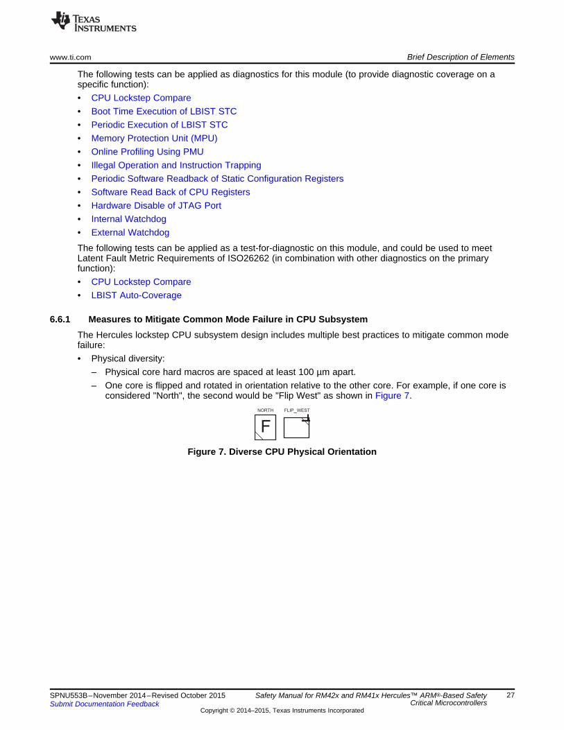
FNORTH FLIP_WEST
F
www.ti.com Brief Description of Elements
The following tests can be applied as diagnostics for this module (to provide diagnostic coverage on aspecific function):• CPU Lockstep Compare• Boot Time Execution of LBIST STC• Periodic Execution of LBIST STC• Memory Protection Unit (MPU)• Online Profiling Using PMU• Illegal Operation and Instruction Trapping• Periodic Software Readback of Static Configuration Registers• Software Read Back of CPU Registers• Hardware Disable of JTAG Port• Internal Watchdog• External Watchdog
The following tests can be applied as a test-for-diagnostic on this module, and could be used to meetLatent Fault Metric Requirements of ISO26262 (in combination with other diagnostics on the primaryfunction):• CPU Lockstep Compare• LBIST Auto-Coverage
6.6.1 Measures to Mitigate Common Mode Failure in CPU SubsystemThe Hercules lockstep CPU subsystem design includes multiple best practices to mitigate common modefailure:• Physical diversity:
– Physical core hard macros are spaced at least 100 µm apart.– One core is flipped and rotated in orientation relative to the other core. For example, if one core is
considered "North", the second would be "Flip West" as shown in Figure 7.
Figure 7. Diverse CPU Physical Orientation
27SPNU553B–November 2014–Revised October 2015 Safety Manual for RM42x and RM41x Hercules™ ARM®-Based SafetyCritical MicrocontrollersSubmit Documentation Feedback
Copyright © 2014–2015, Texas Instruments Incorporated

CPU 1 CPU 2
2 cycles delay
2 cycles delay
CCM-R4compare
CCM-R4
CPU1CLK
CPU2CLK
compareerror
ESM
(ErrorSignalingModule)
Master CPU Checker CPU
Brief Description of Elements www.ti.com
• Temporal diversity:– Timing delay blocks are inserted to delay the operation of the CPUs by two cycles as shown in
Figure 8.
Figure 8. Lockstep Temporal Diversity
– The CPU clock domain is split into two clock trees such that clocks are delivered to the two CPUsby separate paths.
• Power diversity:– Each core has a dedicated power ring.
6.6.2 Notes• Many safety critical microcontrollers utilize a software-based test of CPU functionality as opposed to a
hardware scheme such as the TI LBIST STC. TI does not recommend such tests for a CPU of mediumto high complexity, such as the Cortex-R4. Software-based options have higher memory cost, lowerdetection capability, and longer execution times than the equivalent LBIST STC solution.
• Due to the lockstep diagnostic, it is not necessary to execute a periodic test of CPU control registerconfiguration. A control register disturb in one CPU should not impact the second CPU.
6.7 Primary Embedded FlashThe primary embedded Flash memory is a non-volatile memory that is tightly coupled to the ATCM port ofthe Cortex-R4 CPU core. The ATCM Flash memory is primarily used for CPU instruction access, thoughdata access is also possible. Access to the Flash memory can take multiple CPU cycles. A Flash wrapperlogic provides multiple pipelined read buffers to improve CPU access time on sequential address fetches.
The following tests can be applied as diagnostics for this module (to provide diagnostic coverage on aspecific function):• Flash Data ECC• Hard Error Cache and Livelock• Flash Wrapper Address ECC• Address and Control Parity• Boot Time Check of Flash Memory Contents by Hardware CRC
28 Safety Manual for RM42x and RM41x Hercules™ ARM®-Based Safety SPNU553B–November 2014–Revised October 2015Critical Microcontrollers Submit Documentation Feedback
Copyright © 2014–2015, Texas Instruments Incorporated

www.ti.com Brief Description of Elements
• Periodic Check of Flash Memory Contents by Hardware CRC• Bit Multiplexing in Flash Memory Array• Flash Sector Protection• Periodic Software Readback of Static Configuration Registers• Software Readback of Written Configuration
The following tests can be applied as a test-for-diagnostic on this module, and could be used to meetLatent Fault Metric Requirements of ISO26262 (in combination with other diagnostics on the primaryfunction):• Flash Wrapper Diag Mode 5 Test• Flash Wrapper Diag Mode 7• Software Test of Parity Logic• Software Test of Flash Sector Protection Logic• Software Test of Hardware CRC• CRC Auto-Coverage• Internal Watchdog• External Watchdog• CPU Lockstep Compare• SRAM Data ECC
6.7.1 Notes• When exporting ECC error events from CPU to Flash wrapper and from the Flash wrapper to ESM,
care should be taken that the error is not due to discarded prefetch or other branch discontinuity.• By executing a CRC read back of Flash contents while ECC is enabled on the Flash, it is possible to
perform two diagnostics of the Flash in parallel.• The Flash module may have unique power supply pins depending on the product configuration. It is
highly recommended to implement voltage supervision on these pins as described in the power supplysection.
• The Flash module may have unique test signal pins depending on the product configuration. Forproper board level management of these signals, see the device-specific data sheet.
6.8 Flash EEPROM Emulation (FEE)The Hercules platform architecture includes the capability for a separate bank of Flash memory to be usedas Flash EEPROM Emulation (FEE). FEE is used for data storage only, and cannot be used as a CPUinstruction memory. FEE is a level two memory that is accessed by the CPU over the AXI master port asopposed to the tightly coupled memory interface used for the main Flash banks. The emulation ofEEPROM in the FEE memory is managed by specific FEE drivers running on the CPU.
The following tests can be applied as diagnostics for this module (to provide diagnostic coverage on aspecific function):• FEE Data ECC• Boot Time Check of FEE Memory Contents by Hardware CRC• Periodic Check of FEE Memory Contents by Hardware CRC• Bit Multiplexing in FEE Array• FEE Sector Protection• Periodic Software Readback of Static Configuration Registers• Software Readback of Written Configuration• Flash Wrapper Address ECC
The following tests can be applied as a test-for-diagnostic on this module, and could be used to meetLatent Fault Metric Requirements of ISO26262 (in combination with other diagnostics on the primaryfunction):
29SPNU553B–November 2014–Revised October 2015 Safety Manual for RM42x and RM41x Hercules™ ARM®-Based SafetyCritical MicrocontrollersSubmit Documentation Feedback
Copyright © 2014–2015, Texas Instruments Incorporated

Brief Description of Elements www.ti.com
• Flash Wrapper Diag Mode 1 Test• Flash Wrapper Diag Mode 2 Test• Flash Wrapper Diag Mode 3 Test• Flash Wrapper Diag Mode 4 Test• Software Test of Flash Sector Protection Logic• Software Test of Hardware CRC• CRC Auto-Coverage• Internal Watchdog• External Watchdog• CPU Lockstep Compare• Flash Data ECC• SRAM Data ECC
6.8.1 Notes• As all application FEE accesses are run through a software driver to manage EEPROM emulation, any
diagnostics must respect the functionality of the FEE driver.• The FEE module may have unique power supply pins depending on the product configuration. It is
highly recommended to implement voltage supervision on these pins as described in the power supplysection.
• The FEE module may have unique test signal pins depending on the product configuration. For properboard level management of these signals, see the device-specific data sheet.
6.9 Primary Embedded SRAMThe primary embedded SRAM is a volatile memory that is tightly coupled to the BTCM ports of the Cortex-R4 CPU core. The BTCM SRAMs are primarily used for CPU data access, though instruction access isalso possible. The SRAM has much faster access time than Flash memory, such that no wait states arenecessary at maximum CPU frequency.
Two 64-bit BTCM interfaces are implemented: BTCM0 and BTCM1. It is possible for the CPU to generatetwo BTCM accesses in one cycle: one on BTCM0 and one on BTCM1. The SRAM addressing isinterleaved across the two BTCM interfaces on a 64-bit basis, resulting in significantly reduced arbitrationtime between multiple BTCM masters (PFU, LSU, and AXI-S)
The following tests can be applied as diagnostics for this module (to provide diagnostic coverage on aspecific function):• Data ECC• Hard Error Cache and Livelock• Correctable ECC Profiling• Address and Control Bus Parity• Redundant Address Decode• Data and ECC Storage in Multiple Physical Banks• Boot Time PBIST Check of Primary SRAM• Periodic PBIST Check of Primary SRAM• Bit Multiplexing in Primary SRAM Array• Periodic Hardware CRC Check of Primary SRAM Contents• Periodic Software Readback of Static Configuration Registers• Software Readback of Written Configuration
30 Safety Manual for RM42x and RM41x Hercules™ ARM®-Based Safety SPNU553B–November 2014–Revised October 2015Critical Microcontrollers Submit Documentation Feedback
Copyright © 2014–2015, Texas Instruments Incorporated

www.ti.com Brief Description of Elements
The following tests can be applied as a test-for-diagnostic on this module, and could be used to meetLatent Fault Metric Requirements of ISO26262 (in combination with other diagnostics on the primaryfunction):• Software Test of SRAM Wrapper Redundant Address Decode and ECC• Software Test of Parity Logic• Software Test of PBIST• PBIST Auto-Coverage• Software Test of ECC Profiler• Redundant Address Decode Self Test• Software Test of Hardware CRC• CRC Auto-Coverage• Internal Watchdog• External Watchdog• CPU Lockstep Compare• Flash Data ECC
6.9.1 Notes• There are two SRAM wrappers, one for each BTCM interface. Ensure that you configure both SRAM
wrappers if configuration is needed to support a diagnostic.• By executing a CRC read back of SRAM contents while ECC is enabled on the SRAM, it is possible to
perform two diagnostics of the SRAM in parallel.• The SRAM module may have unique power supply pins depending on the product configuration. It is
highly recommended to implement voltage supervision on these pins as described in the power supplysection.
• The redundant address decode does not provide hardware fault tolerance. As such, the logic may notbe considered fully redundant per the definition of redundancy in some safety standards.
6.10 Level 2 and Level 3 (L2 and L3) Interconnect SubsystemThe system interconnect is composed of a number of bridges, gaskets, communications crossbars, androuting logic, which connects the bus masters (CPU, TUs, and so forth) to L2 slaves and L3 peripherals.This logic, while having no explicit safety critical purpose, is an intermediary in the transfer of safety criticalcommunications.
The following tests can be applied as diagnostics for this module (to provide diagnostic coverage on aspecific function):• Error Trapping (Including Peripheral Slave Error Trapping)• PCR Access Management• Information Redundancy• Periodic Software Readback of Static Configuration Registers• Boot Time Software Test of Basic Functionality Including Error Tests• Periodic Software Test of Basic Functionality Including Error Tests• Software Readback of Written Configuration• Transmission Redundancy• Internal Watchdog• External Watchdog
The following tests can be applied as a test-for-diagnostic on this module, and could be used to meetLatent Fault Metric Requirements of ISO26262 (in combination with other diagnostics on the primaryfunction):• CPU Lockstep Compare• Flash Data ECC
31SPNU553B–November 2014–Revised October 2015 Safety Manual for RM42x and RM41x Hercules™ ARM®-Based SafetyCritical MicrocontrollersSubmit Documentation Feedback
Copyright © 2014–2015, Texas Instruments Incorporated

Brief Description of Elements www.ti.com
• SRAM Data ECC
6.10.1 Notes• An end to end communications safety mechanism implemented on a networked peripheral provides an
indirect form of information redundancy diagnostic on the L2 and L3 interconnect.• The only module in the L2 and L3 interconnect subsystem that has memory-mapped registers is the
PCR.
6.11 EFuse Static ConfigurationThe Hercules platform devices support a manufacturing time configuration of certain functionality (such astrim values for analog macros) via one time programmable (OTP) EFuse structures. The EFuses are readautomatically after power-on reset by an autoload function.
The following tests can be applied as diagnostics for this module (to provide diagnostic coverage on aspecific function):• Boot Time Autoload Self Test• E-Fuse ECC• Periodic Software Readback of Static Configuration Registers• Software Readback of Written Configuration
The following tests can be applied as a test-for-diagnostic on this module, and could be used to meetLatent Fault Metric Requirements of ISO26262 (in combination with other diagnostics on the primaryfunction):• Autoload Self Test Auto-Coverage• EFuse ECC Logic Self Test• Internal Watchdog• External Watchdog• CPU Lockstep Compare• Flash Data ECC• SRAM Data ECC
6.12 OTP Static ConfigurationThe Hercules platform devices support a manufacturing time configuration of certain functionality (such asendianness and the initial configuration of power domains after reset) via one time programmable Flashmemory. The OTP configuration values are read automatically after warm reset by an autoload function.
The following tests can be applied as diagnostics for this module (to provide diagnostic coverage on aspecific function):• OTP ECC• Periodic Software Readback of Static Configuration Registers• Software Readback of Written Configuration• Boot Time Hardware CRC Check of OTP Contents• Periodic Hardware CRC Check of OTP Contents• Bit Multiplexing in Flash Memory Array• Flash Sector Protection
The following tests can be applied as a test-for-diagnostic on this module, and could be used to meetLatent Fault Metric Requirements of ISO26262 (in combination with other diagnostics on the primaryfunction):• Flash Wrapper Diag Mode 1 Test• Flash Wrapper Diag Mode 2 Test• Flash Wrapper Diag Mode 3 Test
32 Safety Manual for RM42x and RM41x Hercules™ ARM®-Based Safety SPNU553B–November 2014–Revised October 2015Critical Microcontrollers Submit Documentation Feedback
Copyright © 2014–2015, Texas Instruments Incorporated

www.ti.com Brief Description of Elements
• Flash Wrapper Diag Mode 4 Test• Software Test of Flash Sector Protection Logic• Software Test of Hardware CRC• CRC Auto-Coverage• Internal Watchdog• External Watchdog• CPU Lockstep Compare• Flash Data ECC• SRAM Data ECC
6.12.1 NotesThe OTP Flash memory used for storage of the configuration words can be read by the CPU.
6.13 I/O Multiplexing Module (IOMM)The I/O multiplexing module (IOMM) provides software configurable mapping of internal module I/Ofunctionality to device pins.
The following tests can be applied as diagnostics for this module (to provide diagnostic coverage on aspecific function):• Locking Mechanism For Control Registers• Master ID Filtering• Error Trapping• Periodic Software Readback of Static Configuration Registers• Boot Time Software Test of Function Using I/O Loopback• Periodic Software Test of Function Using I/O Loopback• Software Readback of Written Configuration
The following tests can be applied as a test-for-diagnostic on this module, and could be used to meetLatent Fault Metric Requirements of ISO26262 (in combination with other diagnostics on the primaryfunction):• Internal Watchdog• External Watchdog• CPU Lockstep Compare• Flash Data ECC• SRAM Data ECC
6.13.1 NotesSoftware testing of the IOMM can be combined with peripheral loopback testing.
6.14 Vectored Interrupt Module (VIM)The vectored interrupt module (VIM) is used to interface peripheral interrupts to the Cortex-R4 CPU. TheVIM provides programmable interrupt prioritization, masking, and sleep mode wake up functionality. TheVIM includes a local SRAM that is used to hold the address of the interrupt handler per channel.
The following tests can be applied as diagnostics for this module (to provide diagnostic coverage on aspecific function):• VIM SRAM Data Parity• Boot Time PBIST Check of VIM SRAM• Periodic PBIST Check of VIM SRAM
33SPNU553B–November 2014–Revised October 2015 Safety Manual for RM42x and RM41x Hercules™ ARM®-Based SafetyCritical MicrocontrollersSubmit Documentation Feedback
Copyright © 2014–2015, Texas Instruments Incorporated

Brief Description of Elements www.ti.com
• Bit Multiplexing in VIM SRAM Array• Periodic Hardware CRC Check of VIM SRAM Contents• Boot Time Software Test of VIM Functionality Including Error Tests• Periodic Software Test of VIM Functionality Including Error Tests• Periodic Software Readback of Static Configuration Registers• Software Readback of Written Configuration• Internal Watchdog• External Watchdog• CPU Memory Protection Unit (MPU)• Online Profiling Using PMU
The following tests can be applied as a test-for-diagnostic on this module, and could be used to meetLatent Fault Metric Requirements of ISO26262 (in combination with other diagnostics on the primaryfunction):• Software test of Parity Logic• PBIST Test of Parity Bit Memory• Software Test of Hardware CRC• CRC Auto-Coverage• Software Test of PBIST• PBIST Auto-Coverage• CPU Lockstep Compare• Flash Data ECC• SRAM Data ECC
6.14.1 NotesCare should be taken to optimize any VIM software diagnostics for the mode of operation - legacy IRQand FIQ, legacy vectored, or fully hardware vectored.
6.15 Real Time Interrupt (RTI)The real time interrupt (RTI) module provides the operating system timer for the device. The OS timerfunction is used to generate internal event triggers or interrupts as needed to provide periodic operation ofsafety critical functions.
The following tests can be applied as diagnostics for this module (to provide diagnostic coverage on aspecific function):• 1oo2 Software Voting Using Secondary Free Running Counter• Periodic Software Readback of Static Configuration Registers• Software Readback of Written Configuration
The following tests can be applied as a test-for-diagnostic on this module, and could be used to meetLatent Fault Metric Requirements of ISO26262 (in combination with other diagnostics on the primaryfunction):• External Watchdog• CPU Lockstep Compare• Flash Data ECC• SRAM Data ECC
6.15.1 NotesWhen using one counter to the operating system timebase counter, a diverse configuration of clocksource, scaling factor, and so forth can be used to reduce probability of common mode failure.
34 Safety Manual for RM42x and RM41x Hercules™ ARM®-Based Safety SPNU553B–November 2014–Revised October 2015Critical Microcontrollers Submit Documentation Feedback
Copyright © 2014–2015, Texas Instruments Incorporated
www.ti.com Brief Description of Elements
6.16 High-End Timer (N2HET), HET Transfer Unit (HTU)The N2HET module is a programmable timer with input/output capabilities. The N2HET is implemented asa simple RISC processor with instruction set dedicated for timing operations. Complex inputs can becaptured and pre-processed by the N2HET for later processing by the CPU. Output generation is typicallypulse width modulation (PWM), but may also be simple general-purpose input/output (GIO) type signals.
N2HET has a dedicated micro DMA controller called HTU. The HTU provides a high bandwidthconnection for data transfer to and from N2HET from and to CPU memories.
The following tests can be applied as diagnostics for this module (to provide diagnostic coverage on aspecific function):• Memory Protection Unit for HTU Bus Master Accesses• Information Redundancy Techniques• Use of DCC as Program Sequence Watchdog• Boot Time Software Test of Function Using I/O Loopback• Periodic Software Test of Function Using I/O Loopback• N2HET/HTU SRAM Data Parity• Boot Time PBIST Check of N2HET/HTU SRAM• Periodic PBIST Check of N2HET/HTU SRAM• Bit Multiplexing in N2HET/HTU SRAM Array• Periodic Hardware CRC Check of N2HET/HTU SRAM Contents• Periodic Software Readback of Static Configuration Registers• Software Readback of Written Configuration• Transmission Redundancy for Transfer Unit• Boot Time Software test of Function Using I/O Checking In GIO Mode• Periodic Software test of Function Using I/O Checking In GIO Mode• Information Redundancy Techniques (while in GIO Mode)• Hardware Disable of JTAG Port
The following tests can be applied as a test-for-diagnostic on this module, and could be used to meetLatent Fault Metric Requirements of ISO26262 (in combination with other diagnostics on the primaryfunction):• Software test of Parity Logic• PBIST Test of Parity Bit Memory• Software Test of Hardware CRC• CRC Auto-Coverage• Software Test of PBIST• PBIST Auto-Coverage• Software Test of MPU Functionality• Software Test of DCC Functionality• Internal Watchdog• External Watchdog• CPU Lockstep Compare• Flash Data ECC• SRAM Data ECC
6.16.1 Notes• Information redundancy techniques used on N2HET can be extended to also cover the HTU bus
master operation.
35SPNU553B–November 2014–Revised October 2015 Safety Manual for RM42x and RM41x Hercules™ ARM®-Based SafetyCritical MicrocontrollersSubmit Documentation Feedback
Copyright © 2014–2015, Texas Instruments Incorporated

Brief Description of Elements www.ti.com
• To reduce probability of common mode failure, user should consider implementing multiple channels(information redundancy) using non adjacent pins.
6.17 Multi-Buffered Analog-to-Digital Converter (MibADC)The MibADC module is used to convert analog inputs into digital values. Results are stored in internalSRAM buffers for later transfer by CPU.
The following tests can be applied as diagnostics for this module (to provide diagnostic coverage on aspecific function):• Hardware Disable of JTAG Port• Boot Time Input Self Test• Boot Time Converter Calibration• Periodic Converter Calibration• MibADC Information Redundancy Techniques• MibADC SRAM Data Parity• Boot Time PBIST Check of MibADC SRAM• Periodic PBIST Check of MibADC SRAM• Bit Multiplexing in MibADC SRAM Array• Periodic Hardware CRC Check of MibADC SRAM Contents• Periodic Software Readback of Static Configuration Registers• Software Readback of Written Configuration• Boot Time Software Test of Function Using I/O Checking In GIO Mode• Periodic Software Test of Function Using I/O Checking In GIO Mode• Information Redundancy Techniques (while in GIO Mode)
The following tests can be applied as a test-for-diagnostic on this module, and could be used to meetLatent Fault Metric Requirements of ISO26262 (in combination with other diagnostics on the primaryfunction):• Software test of Parity Logic• PBIST Test of Parity Bit Memory• Software Test of Hardware CRC• CRC Auto-Coverage• Software Test of PBIST• PBIST Auto-Coverage• Internal Watchdog• External Watchdog• CPU Lockstep Compare• Flash Data ECC• SRAM Data ECC
6.17.1 Notes• The MibADC module may be referred to as MibADC (Multi Buffered ADC) in some documents.• ADC module voltages should be supervised as noted in Power Supply• To reduce probability of common mode failure, user should consider implementing multiple channels
(information redundancy) using non adjacent pins.
36 Safety Manual for RM42x and RM41x Hercules™ ARM®-Based Safety SPNU553B–November 2014–Revised October 2015Critical Microcontrollers Submit Documentation Feedback
Copyright © 2014–2015, Texas Instruments Incorporated

www.ti.com Brief Description of Elements
6.18 Enhanced Quadrature Encoder Pulse (eQEP)The enhanced quadrature encoder pulse (eQEP) module is used for direct interface with a linear or rotaryincremental encoder to get position, direction, and speed information from a rotating machine for use in ahigh-performance motion and position-control system.
The following tests can be applied as diagnostics for this module (to provide diagnostic coverage on aspecific function):• Boot Time Software Test of Function Including Error Tests• Periodic Software Test of Function Including Error Tests• Information Redundancy Techniques• Periodic Software Readback of Static Configuration Registers• Software Readback of Written Configuration• Quadrature Watchdog
The following tests can be applied as a test-for-diagnostic on this module, and could be used to meetLatent Fault Metric Requirements of ISO26262 (in combination with other diagnostics on the primaryfunction):• Software Test of Quadrature Watchdog Functionality• Internal Watchdog• External Watchdog• CPU Lockstep Compare• Flash Data ECC• SRAM Data ECC
6.18.1 NotesUse of a sensorless positioning algorithm can provide information redundancy through plausibilitychecking of eQEP results.
6.19 Multi Buffered Serial Peripheral Interface (MibSPI)The MibSPI modules provide serial I/O compliant to the MibSPI protocol. MibSPI communications aretypically used for communication to smart sensors and actuators, serial memories, and external logic suchas a watchdog device. The MibSPI modules contain internal SRAM buffers. If not used for MibSPIcommunication, the MibSPI modules support the usage of their I/O as general purpose I/O.
The following tests can be applied as diagnostics for this module (to provide diagnostic coverage on aspecific function):• Boot Time Software Test of Function Using I/O Loopback• Periodic Software Test of Function Using I/O Loopback• Parity in Message• Information Redundancy Techniques• MibSPI SRAM Data Parity• Boot Time PBIST Check of MibSPI SRAM• Periodic PBIST Check of MibSPI SRAM• Bit Multiplexing in MibSPI SRAM Array• Periodic Hardware CRC Check of MibSPI SRAM Contents• Periodic Software Readback of Static Configuration Registers• Software Readback of Written Configuration• Transmission Redundancy• Data Overrun Error Detection• Bit Error Detection
37SPNU553B–November 2014–Revised October 2015 Safety Manual for RM42x and RM41x Hercules™ ARM®-Based SafetyCritical MicrocontrollersSubmit Documentation Feedback
Copyright © 2014–2015, Texas Instruments Incorporated

Brief Description of Elements www.ti.com
• Slave Desync Detection• Slave Timeout Detection• Data Length Error Detection• Hardware Disable of JTAG Port• Boot Time Software Test of Function Using I/O Checking In GIO Mode• Periodic Software Test of Function Using I/O Checking In GIO Mode• Information Redundancy Techniques (while in GIO Mode)
The following tests can be applied as a test-for-diagnostic on this module, and could be used to meetLatent Fault Metric Requirements of ISO26262 (in combination with other diagnostics on the primaryfunction):• Software test of Parity Logic• PBIST Test of Parity Bit Memory• Software Test of Hardware CRC• CRC Auto-Coverage• Software Test of PBIST• PBIST Auto-Coverage• Internal Watchdog• External Watchdog• CPU Lockstep Compare• Flash Data ECC• SRAM Data ECC
6.19.1 NotesIt is possible to use the MIBSPI in standard SPI mode.
6.20 Serial Peripheral Interface (SPI)The SPI modules provide serial I/O compliant to the SPI protocol. SPI communications are typically usedfor communication to smart sensors and actuators, serial memories, and external logic such as awatchdog device. If not used for SPI communication, the SPI modules support the usage of their I/O asgeneral purpose I/O.
The following tests can be applied as diagnostics for this module (to provide diagnostic coverage on aspecific function):• Boot Time Software Test of Function Using I/O Loopback• Periodic Software Test of Function Using I/O Loopback• Parity in Message• Information Redundancy Techniques• Periodic Software Readback of Static Configuration Registers• Software Readback of Written Configuration• Transmission Redundancy• Data Overrun Error Detection• Bit Error Detection• Slave Desync Detection• Slave Timeout Detection• Data Length Error Detection• Hardware Disable of JTAG Port• Boot Time Software Test of Function Using I/O Checking In GIO Mode• Periodic Software Test of Function Using I/O Checking In GIO Mode
38 Safety Manual for RM42x and RM41x Hercules™ ARM®-Based Safety SPNU553B–November 2014–Revised October 2015Critical Microcontrollers Submit Documentation Feedback
Copyright © 2014–2015, Texas Instruments Incorporated

www.ti.com Brief Description of Elements
• Information Redundancy Techniques (while in GIO Mode)
The following tests can be applied as a test-for-diagnostic on this module, and could be used to meetLatent Fault Metric Requirements of ISO26262 (in combination with other diagnostics on the primaryfunction):• Internal Watchdog• External Watchdog• CPU Lockstep Compare• Flash Data ECC• SRAM Data ECC
6.21 Local Interconnect Network (LIN)The LIN module provides serial I/O compliant to the LIN protocol. LIN is a low throughput time triggeredprotocol. The module can also be configured in SCI mode and used as a general purpose serial port. Anexternal transceiver is used for LIN communications.
The following tests can be applied as diagnostics for this module (to provide diagnostic coverage on aspecific function):• Boot Time Software Test of Function Using I/O Loopback• Periodic Software Test of Function Using I/O Loopback• Information Redundancy Techniques• Periodic Software Readback of Static Configuration Registers• Software Readback of Written Configuration• Transmission Redundancy• Overrun Error Detection• Frame Error Detection• Physical Bus Error Detection• No-Response Error Detection• Bit Error Detection• Checksum Error Detection• Parity in Message• Hardware Disable of JTAG Port• Boot Time Software Test of Function Using I/O Checking In GIO Mode• Periodic Software Test of Function Using I/O Checking In GIO Mode• Information Redundancy Techniques (while in GIO Mode)
The following tests can be applied as a test-for-diagnostic on this module, and could be used to meetLatent Fault Metric Requirements of ISO26262 (in combination with other diagnostics on the primaryfunction):• Internal Watchdog• External Watchdog• CPU Lockstep Compare• Flash Data ECC• SRAM Data ECC
6.22 Controller Area Network (DCAN)The DCAN interface provides medium throughput networking with event based triggering, compliant to theCAN protocol. The DCAN modules requires an external transceiver to operate on the CAN network.
The following tests can be applied as diagnostics for this module (to provide diagnostic coverage on aspecific function):
39SPNU553B–November 2014–Revised October 2015 Safety Manual for RM42x and RM41x Hercules™ ARM®-Based SafetyCritical MicrocontrollersSubmit Documentation Feedback
Copyright © 2014–2015, Texas Instruments Incorporated

Brief Description of Elements www.ti.com
• Boot Time Software Test of Function Using I/O Loopback• Periodic Software Test of Function Using I/O Loopback• Information Redundancy Techniques• DCAN SRAM Data Parity• Boot Time PBIST Check of DCAN SRAM• Periodic PBIST Check of DCAN SRAM• Bit Multiplexing in DCAN SRAM Array• Periodic Hardware CRC Check of DCAN SRAM Contents• Periodic Software Readback of Static Configuration Registers• Software Readback of Written Configuration• Transmission Redundancy• Stuff Error Detection• Form Error Detection• Acknowledge Error Detection• Bit Error Detection• CAN Protocol CRC in Message• Hardware Disable of JTAG Port• Boot Time Software Test of Function Using I/O Checking In GIO Mode• Periodic Software Test of Function Using I/O Checking In GIO Mode• Information Redundancy Techniques (while in GIO Mode)
The following tests can be applied as a test-for-diagnostic on this module, and could be used to meetLatent Fault Metric Requirements of ISO26262 (in combination with other diagnostics on the primaryfunction):• Software test of Parity Logic• PBIST Test of Parity Bit Memory• Software Test of Hardware CRC• CRC Auto-Coverage• Software Test of PBIST• PBIST Auto-Coverage• Internal Watchdog• External Watchdog• CPU Lockstep Compare• Flash Data ECC• SRAM Data ECC
6.23 General-Purpose Input/Output (GIO)The GIO module provides digital input capture and digital input/output. There is no processing function inthis block. The GIO is typically used for static or rarely changed outputs, such as transceiver enablesignals, warning lights, and so forth. The GIO can also be used to provide external interrupt inputcapabilities.
The following tests can be applied as diagnostics for this module (to provide diagnostic coverage on aspecific function):• Boot Time Software Test of Function Using I/O Checking In GIO Mode• Periodic Software Test of Function Using I/O Checking In GIO Mode• Information Redundancy Techniques• Periodic Software Readback of Static Configuration Registers• Software Readback of Written Configuration
40 Safety Manual for RM42x and RM41x Hercules™ ARM®-Based Safety SPNU553B–November 2014–Revised October 2015Critical Microcontrollers Submit Documentation Feedback
Copyright © 2014–2015, Texas Instruments Incorporated

www.ti.com Brief Description of Elements
The following tests can be applied as a test-for-diagnostic on this module, and could be used to meetLatent Fault Metric Requirements of ISO26262 (in combination with other diagnostics on the primaryfunction):• Internal Watchdog• External Watchdog• CPU Lockstep Compare• Flash Data ECC• SRAM Data ECC
6.23.1 NotesTo reduce probability of common mode failure, the user should consider implementing multiple channelsusing non adjacent pins.
6.24 JTAG Debug and Test AccessThe Hercules platform supports debug, test, and calibration implemented over an IEEE 1149.1 JTAGdebug port. The physical debug interface is internally connected to a TI debug multiplexor logic(ICEPICK), which arbitrates access to test, debug, and calibration logic. Boundary scan is connected inparallel to the ICEPICK to support usage without preamble scan sequences for easiest manufacturingboard test.
The following tests can be applied as diagnostics for this module (to provide diagnostic coverage on aspecific function):• Hardware Disable of JTAG Port• Lockout of JTAG Access Using AJSM• Internal Watchdog• External Watchdog
6.24.1 NotesBoundary scan access remains possible even on systems locked by AJSM.
6.25 Cortex-R4 Central Processing Unit (CPU) DebugThe Hercules platform supports CPU debugcompliant to the ARM® CoreSight standard. Each CoreSightelement is accessible over a memory-mapped debug bus, which can be accessed by the CPU or theJTAG port. The CPU debug logic includes an independent debug bus master (AHB-AP), and the debugunit inside the CPU. These modules are not recommended to be used during safety critical operation andsafety mechanisms are in place to disable this logic.
The following tests can be applied as diagnostics for this module (to provide diagnostic coverage on aspecific function):• Use of MPUs to Block Access to Memory-Mapped Debug• Use of CoreSight Debug Logic Key Enable Scheme• Hardware Disable of JTAG Port• Lockout of JTAG Access Using AJSM• Internal Watchdog• External Watchdog• CPU Lockstep Compare
41SPNU553B–November 2014–Revised October 2015 Safety Manual for RM42x and RM41x Hercules™ ARM®-Based SafetyCritical MicrocontrollersSubmit Documentation Feedback
Copyright © 2014–2015, Texas Instruments Incorporated

Brief Description of Diagnostics www.ti.com
7 Brief Description of DiagnosticsThis section provides a brief summary of the diagnostic mechanisms available on this device. For adetailed description or implementation details for a diagnostic, see the device-specific technical referencemanual. For information on safety-pertinent information such as test execution time, error reporting time,action on detected faults, and diagnostic operation modes, see Appendix A.
7.1 1oo2 Software Voting Using Secondary Free Running CounterThe RTI module contains at minimum two up-counters that can be used to provide an operating systemtime-tick. While one up-counter is used as the operating system timebase, it is possible to use the secondup counter as a diagnostic on the first, via periodic check via software of the counter values in the twotimers. The PMU CPU cycle counter inside the Cortex-R4 CPU can also be used to support such adiagnostic. Error response, diagnostic testability, and any necessary software requirements are defined bythe software implemented by the system integrator.
7.2 Bit Error DetectionWhen this module transmits information onto it's bus, it can also monitor the bus to ensure that thetransmitted information is appearing as expected on the bus. If the expected values are not read backfrom the bus, the hardware can flag the error and signal an interrupt to the CPU. This feature must beenabled and configured in software.
7.3 Bit Multiplexing in FEE Memory ArrayThe FEE modules implemented in the Hercules architecture have a bit multiplexing scheme implementedsuch that the bits accessed to generate a logical (CPU) word are not physically adjacent. This schemehelps to reduce the probability of physical multi-bit faults resulting in logical multi-bit faults; rather theymanifest as multiple single bit faults. As the SECDED FEE ECC can correct a single bit fault in a logicalword, this scheme improves the usefulness of the FEE ECC diagnostic. Bit multiplexing is a feature of thearchitecture and cannot be modified by the software.
7.4 Bit Multiplexing in Flash Memory ArrayThe Flash modules implemented in the Hercules architecture have a bit multiplexing scheme implementedsuch that the bits accessed to generate a logical (CPU) word are not physically adjacent. This schemehelps to reduce the probability of physical multi-bit faults resulting in logical multi-bit faults; rather theymanifest as multiple single bit faults. As the SECDED Flash ECC can correct a single bit fault in a logicalword, this scheme improves the usefulness of the Flash ECC diagnostic. Bit multiplexing is a feature ofthe architecture and cannot be modified by the software.
7.5 Bit Multiplexing in Primary SRAM Memory ArrayThe SRAM modules implemented in the Hercules architecture have a bit multiplexing schemeimplemented such that the bits accessed to generate a logical (CPU) word are not physically adjacent.This scheme helps to reduce the probability of physical multi-bit faults resulting in logical multi-bit faults;rather they manifest as multiple single bit faults. As the SECDED SRAM ECC can correct a single bit faultin a logical word, this scheme improves the usefulness of the SRAM ECC diagnostic. Bit multiplexing is afeature of the architecture and cannot be modified by the software.
7.6 Bit Multiplexing in Peripheral SRAM Memory ArrayThis module's SRAM is implemented with a bit multiplexing scheme such that the bits accessed togenerate a logical (CPU) word are not physically adjacent. This scheme helps to reduce the probability ofphysical multi-bit faults resulting in logical multi-bit faults; rather they manifest as multiple single bit faults.
42 Safety Manual for RM42x and RM41x Hercules™ ARM®-Based Safety SPNU553B–November 2014–Revised October 2015Critical Microcontrollers Submit Documentation Feedback
Copyright © 2014–2015, Texas Instruments Incorporated

www.ti.com Brief Description of Diagnostics
7.7 CPU Illegal Operation and Instruction TrappingThe Cortex-R4 CPU includes diagnostics for illegal operations and instructions that can serve as safetymechanisms. Many of these traps are not enabled after reset and must be configured by the software.Installation of software handlers to support the hardware illegal operation and instruction trapping is highlyrecommended. For more information on enabling traps, see the Cortex-R4 and Cortex-R4F TechnicalReference Manual located athttp://infocenter.arm.com/help/index.jsp?topic=/com.arm.doc.ddi0363e/index.html. Examples of CPU illegaloperation and instruction traps include:• Illegal instruction• Privilege violation
7.8 CPU Logic Built In Self Test (LBIST)The Hercules family architecture supports the use of a hardware logic BIST (LBIST) engine self testcontroller (STC). This logic is used to provide a very high diagnostic coverage on the lockstep CPUs at atransistor level. This logic utilizes the same design for test (DFT) structures inserted into the device forrapid execution of high quality manufacturing tests, but with an internal test engine rather than externalautomated test equipment (ATE). This technique has proven to be drastically more effective thansoftware-based tests of logic, particularly for the complex logic structures seen in a modern CPU.
The LBIST tests must be triggered by the software. User may elect to run all tests, or only a subset of thetests based on the execution time, which can be allocated to the LBIST diagnostic. This time sliced testfeature enables the LBIST to be used effectively as a runtime diagnostic with execution of test time slicesper safety critical loop as well as a comprehensive test for CPU fault during MCU initialization.
Execution of the LBIST STC results in a much higher level of transistor switching per clock cycle thanduring normal software execution due to the high efficiency of the test. A software control is implementedin the STC that allows the user to reduce the CPU clock for the duration of the test. This feature allows theuser to make a compromise between fast execution with higher current consumption or slower executionwith reduced current consumption.
The LBIST mechanism requires isolation of the CPU from the remainder of device logic while under test. Itis also necessary to perform a complete context save before the LBIST. When test execution is complete,the CPU will be reset. The remainder of device logic continues normal operation. After CPU reset,software should read the system control module SYSESR to identify the reason for the reset and can thenrestore the CPU context.
LBIST logic includes capabilities for testing proper operation of the diagnostic. As the test time for thediagnostic is deterministic, a timeout counter has been included that can detect a failure to complete thetest within expected time. In addition, there is the possibility to force an input error to check error detectionand propagation of the error response at system level. This test is performed as follows:1. Enable the self_check_key and fault_ins bits in the STCSTSCR register.2. Enable STC test interval zero and execute the test3. Upon completion of test, the fail bit should be set to 1 in the STC global status register.4. Disable either or both the self_check_key and fault_ins bits in the STCSTSCR register.5. Restart the self test by programming bit 0 of the STCGCR, causing self test restart.6. Upon completion of the test, the fail bit should be set to 0 in the STC global status register.
7.9 CPU Logic Built In Self Test (LBIST) Auto-CoverageThe LBIST diagnostic is based on a 128-bit signature capture. For a given test, only one code is valid outof 2^128 possibilities. Therefore, if there is a fault in the LBIST logic, it is extremely unlikely that thecorrect passing code will be generated via the fault. The cyclical check applied by the LBIST moduleprovides an inherent level of self checking (auto-coverage), which can be considered for application inlatent fault diagnostics.
43SPNU553B–November 2014–Revised October 2015 Safety Manual for RM42x and RM41x Hercules™ ARM®-Based SafetyCritical MicrocontrollersSubmit Documentation Feedback
Copyright © 2014–2015, Texas Instruments Incorporated

Brief Description of Diagnostics www.ti.com
7.10 CPU Lockstep CompareThe Hercules product family includes a lockstep processor diagnostic. This feature includes the addition ofa diagnostic Cortex-R4 CPU that is combined into a 1oo1D (single channel with diagnostic channel)configuration with the application CPU. Both the application CPU and the diagnostic CPU are fed thesame input signals, which results in both CPUs running the same software. The diagnostic and applicationCPUs should generate the same output. The core compare module (CCM) compares the CPU outputsand flags all mis-compares to the ESM.
The lockstep diagnostic is continually operating from power-on reset. The lockstep checking is disabledwhen the CPU is placed into a halting debug state and can only be restored to operation after asubsequent reset. Lockstep functionality can also be disabled temporarily when executing the self testchecking functionality of the CCM.
During the first cycles of CPU operation after reset, it is necessary to execute a short initialization codethat sets all CPU registers to a known state. This code sequence can be found in the device-specific datasheet. Execution of this code sequence as the first instructions out of reset is mandatory.
The CCM logic provides self test and error forcing capability via software triggered hardware. The self testensures that the CCM compare logic is working properly. The error forcing capability allows you to test thesystem level response to a lockstep mis-compare.
7.11 CPU Lockstep Comparator Self TestThe CPU lockstep comparator (CCM) diagnostic includes self test features to check for proper operationof the lockstep comparator.
7.12 CPU Online Profiling Using the Performance Monitoring UnitThe Cortex-R4 CPU includes a performance monitoring unit (PMU). This logic is intended to be used fordebug and code profiling purposes, but it can also be utilized as a safety mechanism. The PMU includes aCPU cycle counter as well as three additional counters, which can be programmed to count a number ofdifferent CPU events. For a complete list of CPU events that can be monitored, see the Cortex-R4 andCortex-R4F Technical Reference Manual located athttp://infocenter.arm.com/help/index.jsp?topic=/com.arm.doc.ddi0363e/index.html. Examples of the CPUevents that can be monitored include:• Number of cycles in which an ECC or parity error is detected by diagnostics in CPU• Number of cycles in which the CPU is in the livelock state• Number of instructions executed• Number of cycles in which an exception is taken
With such information available, it is possible to generate a software routine that periodically checks thePMU counter values and compares these values to the profile expected during normal operation. ThePMU is not enabled by default and must be configured via software. As the PMU is implemented internalto the CPU, it is checked for proper operation on a cycle by cycle basis by the lockstep diagnostic and canalso be checked via execution of the LBIST STC diagnostic.
7.13 CPU Memory Protection Unit (MPU)The Hercules implementation of the Cortex-R4 CPU includes an MPU. The MPU logic can be used toprovide spatial separation of software tasks in the device memory. It is expected that the operating systemcontrols the MPU and changes the MPU settings based on the needs of each task. A violation of aconfigured memory protection policy results in a CPU abort.
The MPU can also be used to configure the memory ordering policies of the memory system. By default,all peripheral accesses are strongly ordered type - meaning that all transactions complete in the sequencethey are issued and no write transactions are buffered. If desired, the operating system can configureaccesses to be device type - meaning that writes are buffered. This can improve performance over astrongly ordered model, at the cost of some determinism. It is highly recommended that the system controlmodule and other modules deemed to have critical configurations be set to a strongly ordered accessmodel.
44 Safety Manual for RM42x and RM41x Hercules™ ARM®-Based Safety SPNU553B–November 2014–Revised October 2015Critical Microcontrollers Submit Documentation Feedback
Copyright © 2014–2015, Texas Instruments Incorporated

www.ti.com Brief Description of Diagnostics
As the MPU is internal to the CPU core, proper operation is checked via the lockstep CPU mechanism. Inaddition, the LBIST STC diagnostic provides a check of the MPU when it performs a test of the CPU.
7.14 CRC Auto-coverageThe CRC diagnostic is based on a 64-bit polynomial. For a given test, only one code is valid out of 2^64possibilities. Therefore, if there is a fault in the CRC logic, it is extremely unlikely that the correct passingcode will be generated via the fault.
7.15 CRC in MessageThis module includes a CRC in Message safety mechanism. The CRC values are calculated andtransmitted by the transmitter, and then re-calculated by the receiver. If the CRC value calculated by thereceiver does not match the transmitted CRC value, a CRC error will be flagged. Error response and anynecessary software requirements are defined by the system integrator.
7.16 DCAN Acknowledge Error DetectionWhen a node on the CAN network receives a transmitted message, it sends an acknowledgment that itreceived the message successfully. When a transmitted message is not acknowledged by the recipientnode, the transmitting DCAN will flag an Acknowledge Error. Error response and any necessary softwarerequirements are defined by the system integrator.
7.17 DCAN Form Error DetectionCertain types of frames in the DCAN have a fixed format per the CAN protocol. When a receiver receivesa bit in one of these frames that violates the protocol, the module will flag a Form Error. Error responseand any necessary software requirements are defined by the system integrator.
7.18 DCAN Stuff Error DetectionIn the CAN message protocol, several of the frame segments are coded through bit stuffing. Whenever atransmitter detects five consecutive bits of identical value in the bitstream to be transmitted, itautomatically inserts a complementary bit into the actual transmitted bit stream. If a 6th consecutive equalbit is detected in a received segment that should have been coded by bit stuffing, the DCAN module willflag a Stuff Error. Error response and any necessary software requirements are defined by the systemintegrator.
7.19 DCAN Protocol CRC in MessageThe CAN Protocol includes a CRC in Message. The CRC values are calculated and transmitted by thetransmitter, and then re-calculated by the receiver. If the CRC value calculated by the receiver does notmatch the transmitted CRC value, a CRC error will be flagged. Error response and any necessarysoftware requirements are defined by the system integrator.
7.20 Dual Clock Comparator (DCC)One or more dual clock comparators (DCCs) are implemented as multi-purpose safety diagnostics. TheDCC can be used to detect incorrect frequencies and drift between clock sources. The DCC is composedof two counter blocks: one is used as a reference timebase and a second is used for the clock under test.Both reference clock and clock under test may be selected via software, as can the expected ratio of clockfrequencies. Deviation from the expected ratio generates an error indication to the ESM. For moreinformation on the clock selection options implemented, see the device-specific data sheet. For DCCprogramming details, see the device-specific technical reference manual.
The DCC diagnostic is not enabled by default and must be enabled via software. It is possible to disableand configure this diagnostic via software. The cyclical check applied by the DCC module provides aninherent level of self checking (auto-coverage), which can be considered for application in latent faultdiagnostics.
45SPNU553B–November 2014–Revised October 2015 Safety Manual for RM42x and RM41x Hercules™ ARM®-Based SafetyCritical MicrocontrollersSubmit Documentation Feedback
Copyright © 2014–2015, Texas Instruments Incorporated
Brief Description of Diagnostics www.ti.com
7.21 Efuse Autoload Self TestThe EFuse controller has a self test logic that executes automatically after autoload completion. This is nota diagnostic that can be run separately, but is a given when Autoload self test executes. The test can besubsequently triggered by the software. Error is indicated via ESM.
7.22 Efuse Autoload Self Test Auto-CoverageAs a test-for-diagnostic the Autoload self test logic implementation provides test coverage for its logic.This is not a diagnostic that can be run separately, but is a given when Autoload self test executes.
7.23 EFuse ECCThe EFuses utilize a SECDED ECC diagnostic to detect (and correct) incorrect configuration values.Errors are indicated via ESM. Use of the EFuse ECC diagnostic is mandatory. The cyclical check appliedby the ECC logic provides an inherent level of self checking (auto-coverage), which can be considered forapplication in latent fault diagnostics.
7.24 EFuse ECC Logic Self TestAs a test-for-diagnostic, it is possible to test the functionality of the Efuse ECC logic by performing a selftest supported by hardware and checking for errors
7.25 eQEP Quadrature WatchdogThe eQEP peripheral contains a 16-bit watchdog timer that monitors the quadrature-clock to indicateproper operation of the motion-control system. The eQEP watchdog timer is clocked from VCLK/64 andthe quadrate clock event (pulse) resets the watchdog timer. If no quadrature-clock event is detected until aperiod match, then the watchdog timer will time out and the watchdog interrupt flag will be set. The time-out value is programmable through the watchdog period register.
7.26 eQEP Software Test of Quadrature Watchdog FunctionalityA software test can be used to test for basic functionality of the quadrature watchdog as well as to injectdiagnostic errors and check for proper error response. Such a test can be executed at boot or periodically.Software requirements necessary are defined by the software implemented by the system integrator.
7.27 Error Trapping - IOMMThe IOMM can trap address and privilege errors on received transactions. Transactions that attempt toaccess un-implemented locations in the IOMM chip select result in an ESM response. Transactions thatare not in privileged mode also generate an ESM response.
This feature is enabled after reset. Software cannot disable this feature.
7.28 Error Trapping (including Peripheral Slave Error Trapping) - L2/L3 InterconnectThe L2 and L3 interconnect subsystem includes a number of mechanisms to detect and trap errors.Address decoders in the diagnostic respond with a bus error to the initiator if a bus transaction does notdecode to a valid target. Logic is also present that can detect the timeout of certain transactions andrespond with a bus error to the transaction initiator. In addition to testing for slaves directly connected tothe L2 interconnect, peripheral slaves which are connected to L3 (PCR) peripheral interconnect cansupport error trapping.
The interconnect error trapping functionality is enabled by default and cannot be disabled by the software.These features can be tested via software through the insertion of invalid bus transactions.
46 Safety Manual for RM42x and RM41x Hercules™ ARM®-Based Safety SPNU553B–November 2014–Revised October 2015Critical Microcontrollers Submit Documentation Feedback
Copyright © 2014–2015, Texas Instruments Incorporated

www.ti.com Brief Description of Diagnostics
7.29 External Monitoring of Warm Reset (nRST)The nRST warm reset signal is implemented as an I/O. An external monitor can be utilized to detectexpected or unexpected changes to the state of the internal warm reset control signal. Error response,diagnostic testability, and any necessary software requirements are defined by the external monitorselected by the system integrator.
7.30 External Monitoring via ECLKThe Hercules platform provides the capability to export select internal clocking signals for externalmonitoring. This feature can be configured via software by programming registers in the system controlmodule. To determine the number of external clock outputs implemented and the register mapping ofinternal clocks that can be exported, see the device-specific data sheet.
Export of internal clocks on the ECLK outputs is not enabled by default and must be enabled via software.It is possible to disable and configure this diagnostic via software.
7.31 External Voltage SupervisorThe Hercules platform highly recommends the use of an external voltage supervisor to monitor all voltagerails. The voltage supervisor should be configured with overvoltage and undervoltage thresholds matchingthe voltage ranges supported by the target device (as noted in the device-specific data sheet). Errorresponse, diagnostic testability, and any necessary software requirements are defined by the externalvoltage supervisor selected by the system integrator.
7.32 External WatchdogWhen using an external watchdog, there is a possibility to reduce common mode failure with the MCUclocking system, as the watchdog can utilize clock, reset, and power that are separate from the systembeing monitored. Error response, diagnostic testability, and any necessary software requirements aredefined by the external watchdog selected by the system integrator. The Hercules platform highlyrecommends the use of an external watchdog over the internally provided watchdogs.
An internal or external watchdog can provide an indication of inadvertent activation of logic which resultsin impact to safety critical execution. Any watchdog added externally should include a combination oftemporal and logical monitoring of program sequence or other appropriate methods such that highdiagnostic effectiveness can be claimed.
7.33 FEE Contents Check by Hardware CRCThe platform includes a hardware CRC implementing the ISO CRC-64 standard polynomial. The CRCmodule can be used to test the integrity of FEE contents by calculating a CRC for all FEE contents andcomparing this value to a previously generated "golden" CRC. The read of FEE contents to the CRC canbe done by the CPU. The comparison of results, indication of fault, and fault response are theresponsibility of the software managing the test. Depending on the software driver scheme used tosupport FEE, it may be necessary to execute this check driven by the CPU FEE driver. It is highlyrecommended to perform a CRC integrity check of FEE contents at boot time. The cyclical check appliedby the hardware CRC module provides an inherent level of self checking (auto-coverage), which can beconsidered for application in latent fault diagnostics.
7.34 FEE Data ECCThe on-chip FEE memory is supported by SECDED ECC diagnostic. Unlike the main Flash memory, theFEE memory utilizes a local SECDED ECC controller implemented in the Flash wrapper. This allows extraflexibility needed to support EEPROM emulation, but does leave the full transaction path between CPUand FEE memory without end-to-end diagnostics.
The FEE SECDED ECC controller utilizes the same ECC algorithm as used in the main Flash memory; 8-bit of code are implemented per 64-bit of data. All detection of ECC faults is performed in the Flashwrapper. Error response is provided via bus error to the CPU and an error signal to ESM. The errorresponse has added programmability to support multiple EEPROM emulation strategies desired by TIcustomers. Fault addresses are logged in the Flash wrapper.
47SPNU553B–November 2014–Revised October 2015 Safety Manual for RM42x and RM41x Hercules™ ARM®-Based SafetyCritical MicrocontrollersSubmit Documentation Feedback
Copyright © 2014–2015, Texas Instruments Incorporated
Brief Description of Diagnostics www.ti.com
The ECC logic for the FEE is disabled at reset and must be configured in the Flash wrapper. The cyclicalcheck applied by the FEE ECC logic provides an inherent level of self checking (auto-coverage), whichcan be considered for application in latent fault diagnostics.
7.35 FEE Sector ProtectionIt is possible to prevent a write operation on an FEE sector by the software configuration of the Flashwrapper. The sector protection registers, BSE, contain a bit for each sector in the FEE bank, whichenables or disables a sector for write operation. The BSE register can only be written in privilege modewhile the software PROTLIDIS protection bit is set high. This mechanism can reduce probability ofunintended programming of FEE memory.
7.36 Flash ATCM Address and Control Bus ParityThe on-chip ATCM bus connection to Flash memory is supported by a parity diagnostic on the addressand control signals. The parity is generated by the CPU and evaluated by the Flash wrapper. Detectederrors are signaled to the ESM by the Flash wrapper and the error address is captured in the Flashwrapper.
This diagnostic is enabled at reset. The diagnostic can be disabled by programmation of theBUS_PAR_DIS key in the FPAR_OVR register of the Flash wrapper.
7.37 Flash Contents Check by Hardware CRCThe platform includes a hardware cyclic redundancy check (CRC) implementing the ISO CRC-64 standardpolynomial. The CRC module can be used to test the integrity of Flash contents by calculating a CRC forall Flash contents and comparing this value to a previously generated "golden" CRC. The read of Flashcontents to the CRC can be done by CPU. The comparison of results, indication of fault, and faultresponse are the responsibility of the software managing the test. It is highly recommended to perform aCRC integrity check of Flash contents at boot time. The cyclical check applied by the hardware CRCmodule provides an inherent level of self checking (auto-coverage), which can be considered forapplication in latent fault diagnostics.
7.38 Flash ECCThe on-chip Flash memory is supported by single error correction, dual error detection (SECDED) error-correcting code (ECC) diagnostic. It is connected by a 64-bit-wide data bus interface (ATCM) to theCortex-R4 CPU. In this SECDED scheme, an 8-bit code word is used to store the ECC data as calculatedover the 64-bit data bus.
The ECC logic for the ATCM Flash access is located in the Cortex-R4 CPU. All ATCM transactions haveECC on the data payload. ECC evaluation is done by the ECC control logic inside the CPU. This schemeprovides end-to-end diagnostics on the transmissions between the CPU and Flash memory. Detecteduncorrectable errors result in a processor abort or bus error depending on the requesting master.Detected correctable errors can be corrected or not corrected, depending on whether correctionfunctionality is enabled. The address of the memory, which includes the ECC error, is logged in the CPU.For more details, see the Cortex-R4 and Cortex-R4F Technical Reference Manual located athttp://infocenter.arm.com/help/index.jsp?topic=/com.arm.doc.ddi0363e/index.html.
It is possible to export error detection events from the CPU to the Flash wrapper, and then from the Flashwrapper to the ESM. This functionality is not enabled by default and must be configured by the software.The Cortex-R4 PMU must first be set to export events to an external monitor. Then the Flash wrappermust be configured to export the correctable and uncorrectable events to the ESM.
The ECC logic for the Flash is disabled at reset and must be configured in both the CPU and the Flashwrapper. The diagnostic has separate controls for checking, correction, and read and modify and writefunctionality in the system control coprocessor that must be enabled via software. As the ECC diagnosticis implemented inside the CPU, its behavior is continuously checked via the lockstep functionality and canalso be tested via the LBIST STC. The cyclical check applied by the ECC module provides an inherentlevel of self checking (auto-coverage), which can be considered for application in latent fault diagnostics.
48 Safety Manual for RM42x and RM41x Hercules™ ARM®-Based Safety SPNU553B–November 2014–Revised October 2015Critical Microcontrollers Submit Documentation Feedback
Copyright © 2014–2015, Texas Instruments Incorporated

www.ti.com Brief Description of Diagnostics
7.39 Flash Hard Error Cache and LivelockIf ECC correction is enabled, corrected data values are stored in an internal one entry hard error cache. Itis not possible to automatically re-write the corrected data values back to the Flash, as the Flash is a non-volatile memory that has special programming requirements.
A single instruction and its data may not have more than one correctable error. In case more than onecorrectable error is detected, it is possible to overrun the hard error cache and put the processor into aninoperable livelock state. Cases that can generate a livelock include:• Two single bit errors in a 64-bit unaligned 32-bit Thumb-2 instruction fetch• A single bit error in a load instruction (LDR or LDM) followed by a single bit error in the instruction's
data payload
Livelock is indicated via the ESM and typically requires a reset for recovery to be attempted. Livelock on aFlash interface transaction can be an indication of severe permanent fault in the Flash memory.
Use of the hard error cache and livelock functionality is mandatory. This feature is enabled at reset andcannot be disabled by the software.
7.40 Flash Sector ProtectionIt is possible to prevent a write operation on a sector by the software configuration of the Flash wrapper.The sector protection registers, Bank Sector Enable Register (BSE), contain a bit for each sector in theFlash bank, which enables or disables a sector for write operation. The BSE register can only be written inprivilege mode while the software PROTLIDIS protection bit is set high. This mechanism can reduceprobability of unintended programming of Flash memory.
7.41 Flash Wrapper Address ECCIn addition to the ECC functionality in the CPU, the Flash wrapper extends the ECC capability to includeaddress. The standard SECDED ECC scheme utilized has 8-bit of code for 64-bit of data. Extensions ofthe Hamming equations allow additional bits of data beyond 64 bits to be encoded into 8 bits of code withthe same Hamming distance. The Flash wrapper design takes advantage of this by incorporating the TCMbus address of the transaction into the Flash memory ECC calculation. All values stored in the Flashmemory have the address added into the Flash ECC. Upon read of data from Flash, the Flash wrapperwill strip the address component from the ECC and provide the regenerated ECC code to the CPU. Errorsin the address result in a multi-bit ECC failure in the CPU.
The address ECC feature is disabled at reset. There are no separate controls for this feature. This featureis enabled whenever ECC is enabled in the Flash wrapper. The cyclical check applied by the Flashwrapper address ECC module provides an inherent level of self checking (auto-coverage), which can beconsidered for application in latent fault diagnostics.
7.42 Flash Wrapper Diag Mode 1 TestThis diagnostic mode provides the capability to test the ECC logic in the Flash Wrapper by corrupting theinput data for ECC comparison. This diag mode can be used to test the FEE and OTP interfaces.
7.43 Flash Wrapper Diag Mode 2 TestThis diagnostic mode provides the capability to check the generated ECC syndrome. This diag mode canbe used to test the FEE and OTP interfaces.
7.44 Flash Wrapper Diag Mode 3 TestThis diagnostic mode provides the capability to test the ECC logic in the Flash Wrapper by corrupting thegenerated ECC syndrome. This diag mode can be used to test the FEE and OTP interfaces.
7.45 Flash Wrapper Diag Mode 4 TestThis diagnostic mode provides the capability to test the ECC logic in the Flash Wrapper by corrupting theECC bits. This diag mode can be used to test the FEE and OTP interfaces.
49SPNU553B–November 2014–Revised October 2015 Safety Manual for RM42x and RM41x Hercules™ ARM®-Based SafetyCritical MicrocontrollersSubmit Documentation Feedback
Copyright © 2014–2015, Texas Instruments Incorporated

Brief Description of Diagnostics www.ti.com
7.46 Flash Wrapper Diag Mode 5 TestAn error can be injected into the lockstep address tag registers to cause a mismatch between primary andduplicate registers. This diag mode can be used to test the Primary Flash interface.
7.47 Flash Wrapper Diag Mode 7 TestIn order to test the ECC logic of the CPU incorrect ECC can be fed into the CPU. In this diagnostic modeone or more specific bits can be flipped. This diag mode can be used to test the Primary Flash interface.
7.48 Glitch Filtering on nRST and nPORRSTGlitch filters are implemented on the cold and warm reset pins of the device. These structures filter outnoise and transient signal spikes on the input reset pins in order to reduce unintended activation of thereset circuitry. The glitch filters are continuously operating and their behavior cannot be changed by thesoftware. Use of the glitch filters is mandatory.
7.49 Hardware CRC Check of OTP ContentsThe platform includes a hardware cyclic redundancy check (CRC) implementing the ISO CRC-64 standardpolynomial. The CRC module can be used to test the integrity of OTP contents by calculating a CRC forall Flash contents and comparing this value to a previously generated "golden" CRC. The read of Flashcontents to the CRC can be done by the CPU. The comparison of results, indication of fault, and faultresponse are the responsibility of the software managing the test. It is highly recommended to perform aCRC integrity check of OTP contents at boot time.
7.50 Hardware Disable of JTAG PortThe JTAG debug port can be physically disabled to prevent JTAG access in deployed systems. Therecommended scheme is to hold test clock (TCK) to ground and hold test mode select (TMS) high, thoughalternate schemes are possible.
Disabling of the JTAG port also provides coverage for inadvertent activation of many debug activities,since these are often initiated via an external debug tool which writes commands to the device using theJTAG port.
7.51 Information Redundancy TechniquesInformation redundancy techniques can be applied via software as an additional runtime diagnostic for thismodule. There are many techniques that can be applied, such as read back of written values and multipleoutput of the same data with comparison of results. Error response, diagnostic testability, and anynecessary software requirements are defined by the software implemented by the system integrator.
7.52 Information Redundancy Techniques - L2/L3 Interconnect SpecificInformation redundancy techniques can be applied via software as an additional runtime diagnostic on theL2 and L3 interconnect. There are many techniques that can be applied, such as read back of writtenvalues and multiple reads of the same target data with comparison of results. Error response, diagnostictestability, and any necessary software requirements are defined by the software implemented by thesystem integrator.
7.53 Information Redundancy Techniques - DCAN SpecificInformation redundancy techniques can be applied via software as an additional runtime diagnostic forCAN communication. There are many techniques that can be applied, such as read back of written valuesand multiple reads of the same target data with comparison of results.
50 Safety Manual for RM42x and RM41x Hercules™ ARM®-Based Safety SPNU553B–November 2014–Revised October 2015Critical Microcontrollers Submit Documentation Feedback
Copyright © 2014–2015, Texas Instruments Incorporated

www.ti.com Brief Description of Diagnostics
In order to provide diagnostic coverage for network elements outside the MCU (wiring harness,connectors, transceiver) end-to-end safing mechanisms are applied. These mechanisms can also providediagnostic coverage inside the MCU. There are many different schemes applied, such as additionalmessage checksums, redundant transmissions, time diversity in transmissions, and so forth. Mostcommonly checksums are added to the payload section of a transmission to ensure the correctness of atransmission. These checksums are applied in addition to any protocol level parity and checksums. As thechecksum is generated and evaluated by the software at either end of the communication, the wholecommunication path is safed, resulting in end-to-end safing.
Error response, diagnostic testability, and any necessary software requirements are defined by the systemintegrator.
7.54 Information Redundancy Techniques - N2HET SpecificInformation redundancy techniques can be applied via software or system as an additional runtimediagnostic on N2HET operations. There are many techniques that can be applied, such as multiplesampling of a single input channel, sampling of two or more input channels, and read back of writtenoutput.
Error response, diagnostic testability, and any necessary software requirements are defined by thesoftware implemented by the system integrator.
7.55 Internal Voltage Monitor (VMON)The Hercules platform incorporates a simple embedded voltage monitor (VMON) that can detect grosslyout of range supply voltages. The VMON operates continuously and requires no software configuration orCPU overhead. VMON monitors the core and I/O supplies. When the supplies are grossly over or underspecified voltages (for product specific values, see the device-specific data sheet), the VMON drives thenPORRST (power-on reset) signal internally. This response holds the device in the safe operating state.When power supplies are in range, the VMON will not interfere with the nPORRST signal. For moreinformation on VMON operation, see the device-specific data sheet.
The VMON is a continuously operating diagnostic. It is not possible to disable the VMON diagnostic. In-system test of the VMON diagnostic is generally not feasible as tight control of external voltages is neededto trigger the VMON error response. If improperly applied, such voltage could result in permanent damageto the MCU. Use of the VMON is mandatory.
7.56 Internal WatchdogThe Hercules platform supports the use of an internal watchdog that is implemented in the real timeinterrupt (RTI) module. The internal watchdog has two modes of operation: digital watchdog (DWD) anddigital windowed watchdog (DWWD). The modes of operation are mutually exclusive, the designer canelect to use one mode or the other but not both at the same time. For details of programming the internalwatchdogs, see the device-specific technical reference manual.
The DWD is a traditional single threshold watchdog. The user programs a timeout value to the watchdogand must provide a predetermined "pet" response to the watchdog before the timeout counter expires.Expiration of the timeout counter or an incorrect "pet" response triggers an error response. The DWD canissue either an internal (warm) system reset or a CPU non-maskable interrupt upon detection of a failure.The DWD is not enabled after reset. Once enabled by the software, the DWD cannot be disabled exceptby system reset or power-on reset. Users should take care not to change the DWD clock source afterenabling the module, else behavior is unpredictable.
The DWWD is a traditional windowed watchdog. The user programs an upper bound and lower bound tocreate a time window during which the software must provide a predetermined "pet" response to thewatchdog. Failure to receive the correct response within the time window or an incorrect "pet" responsetriggers an error response. The DWWD can issue either an internal (warm) system reset or a CPU non-maskable interrupt upon detection of a failure. The DWWD is not enabled after reset. Once enabled by thesoftware, the DWWD cannot be disabled except by system reset or power-on reset. The use of the timewindow allows detection of additional clocking failure modes as compared to the DWD implementation.
An internal or external watchdog can provide an indication of inadvertent activation of logic which resultsin impact to safety critical execution, such as an inadvertent activation of JTAG logic.
51SPNU553B–November 2014–Revised October 2015 Safety Manual for RM42x and RM41x Hercules™ ARM®-Based SafetyCritical MicrocontrollersSubmit Documentation Feedback
Copyright © 2014–2015, Texas Instruments Incorporated

Brief Description of Diagnostics www.ti.com
7.57 IOMM Master ID FilteringThe IOMM checks the master ID of all incoming bus transactions. Only transactions from the CPU areallowed. Illegal transactions result in a bus error response to the offending bus master and the write toIOMM will be discarded. This feature is enabled after reset. Software cannot disable this feature. Use ofthe master ID filtering is mandatory.
7.58 LIN Checksum Error DetectionAfter message reception, the LIN performs a CRC check on all received data bytes. This data is thencompared to the checksum for the message that was transmitted by the sender. If there is a mismatch,the LIN hardware can flag a Checksum Error and generate an interrupt to the CPU. This feature must beenabled and configured in software.
7.59 LIN No-Response Error DetectionIf no response is received within a configurable time period after the LIN master completes a headertransmission, the LIN hardware can flag a No-Response Error and generate an interrupt to the CPU. Thisfeature must be enabled and configured in software.
7.60 LIN Physical Bus Error DetectionIf no message can be generated on the LIN Bus, the LIN hardware can flag the error and generate aphysical bus error and generate an interrupt to the CPU. This feature must be enabled and configured insoftware.
7.61 LIN / SCI Bit Error DetectionWhen this module transmits information on the LIN Bus, it also monitors the LIN Bus to ensure that thetransmitted information is appearing as expected on the LIN Bus. If the expected values are not read backfrom the LIN Bus, the hardware can flag the error and signal an interrupt to the CPU. This feature must beenabled and configured in software.
7.62 LIN / SCI Frame Error DetectionWhen receiving serial data, each byte of information on the SCI has an expected format. If the receivedmessage does not match this error, the SCI hardware can flag an error and generate an interrupt to theCPU. This feature must be enabled and configured in software.
7.63 LIN / SCI Overrun Error DetectionIf the SCI RX buffer receives new data before the previous data has been read, the existing data will beoverwritten and lost. If this occurs, the SCI hardware can flag the error and generate an interrupt to theCPU. This feature must be enabled and configured in software.
7.64 Locking Mechanism for Control RegistersThe IOMM contains a two stage lock mechanism for protection of critical control registers. To change theconfiguration of the pin multiplexing, the user must write two specific 32-bit values to the "kicker" registersin a defined sequence. When complete, the lock function must be reset. Write accesses, when theregisters are locked, will not update the registers, nor will they generate an error response. This feature isenabled after reset. Software can disable the lock by unlocking and never re-locking.
7.65 Lockout of JTAG Access Using AJSMThe Hercules platform includes the Advanced JTAG Security Module (AJSM) as support for managingdebug access on deployed devices. AJSM can be used to program a unique access key to the OTP Flashmemory. Subsequent debug accesses must unlock the AJSM with the correct key sequence in order togain access to the JTAG-based debug, logic. An error in unlocking the AJSM results in no error responseand no access to the debug logic.
52 Safety Manual for RM42x and RM41x Hercules™ ARM®-Based Safety SPNU553B–November 2014–Revised October 2015Critical Microcontrollers Submit Documentation Feedback
Copyright © 2014–2015, Texas Instruments Incorporated
www.ti.com Brief Description of Diagnostics
7.66 Low Power Oscillator Clock Detector (LPOCLKDET)The low-power oscillator clock detector (LPOCLKDET) is a safety diagnostic that can be used to detectfailure of the primary clock oscillator. LPOCLKDET utilizes the embedded high-frequency, low-poweroscillator (HF LPO). The clock detect circuit works by checking for a rising edge on one clock (oscillator orHF LPO) between rising edges of the other clock. The result is that in addition to flagging incorrect,repeating frequencies, the circuit also fails due to transient conditions. The low end of the clock detectwindow ignores a transient low phase of at least 12 HF LPO cycles. Note that this filtering of the transientresponse does not change the input frequency range. The LPOCLKDET circuitry is enabled by defaultduring the power-on reset state. The diagnostic can be disabled via software.
7.67 Memory Protection Unit (MPU) for Non-CPU Bus MastersMany non-CPU bus masters include an MPU. The MPU logic can be used to provide spatial separation ofsoftware tasks in the device memory. It is expected that the module's software driver controls the MPUand changes the MPU settings based on the needs of system implementation. A violation of a configuredmemory protection policy will result in an ESM error. The MPU is not enabled at reset. Software mustenable, configure and test the MPU.
7.68 Memory Protection Unit (MPU) for Cortex R4 CPUThe Hercules implementation of the Cortex-R4 CPU includes an MPU. The MPU logic can be used toprovide spatial separation of software tasks in the device memory. It is expected that the operating systemcontrols the MPU and changes the MPU settings based on the needs of each task. A violation of aconfigured memory protection policy results in a CPU abort. The MPU can also be used to configure thememory ordering policies of the memory system. By default, all peripheral accesses are strongly ordered -meaning that all transactions complete in the sequence are issued and no write transactions are buffered.If desired, the operating system can configure accesses to be device - meaning that writes are buffered.This can improve performance over a strongly ordered model, at the cost of some determinism. It is highlyrecommended that the system control module and other modules deemed to have critical configurationsbe set to a strongly ordered access model. As the MPU is internal to the CPU core, proper operation ischecked via the lockstep CPU mechanism. In addition, the LBIST STC diagnostic provides a check of theMPU when it performs a test of the CPU.
7.69 MibADC Converter CalibrationThe Hercules MibADC module implements calibration logic normally used to improve converter accuracy.This logic can also be used as a safety mechanism. Software comparison of the conversion of knownreference values from the calibration logic can provide a diagnostic on converter functionality. Repeatedexecution of the calibration routine can be used to detect drift during application. Software must configureand enable and evaluate the result of this diagnostic. Error response, diagnostic testability, and anynecessary software requirements are defined by the software implemented by the system integrator.
7.70 MibADC Information Redundancy TechniquesInformation redundancy techniques can be applied via software as an additional runtime diagnostic onADC conversions. There are many techniques that can be applied, such as multiple conversions usingmultiple channels on the same converter or by doing multiple conversions on the same channel followedwith comparison of results. Filtering or a plausibility check for the converted values are in expected rangecan also improve diagnostic coverage. Error response, diagnostic testability, and any necessary softwarerequirements are defined by the software implemented by the system integrator.
7.71 MibADC Input Self TestThe Hercules MibADC module implements an input self test engine that can detect short to ADREFLO,ADREFHI or open input. Software must configure and enable and evaluate the result of this diagnostic.Error response, diagnostic testability, and any necessary software requirements are defined by thesoftware implemented by the system integrator.
53SPNU553B–November 2014–Revised October 2015 Safety Manual for RM42x and RM41x Hercules™ ARM®-Based SafetyCritical MicrocontrollersSubmit Documentation Feedback
Copyright © 2014–2015, Texas Instruments Incorporated

Brief Description of Diagnostics www.ti.com
7.72 MibSPI/SPI Data Length Error DetectionThe MibSPI or SPI can detect an error in the length of either a received or a transmitted message. If thetransmitted or received message does not match the expected length as specified in the charactercounter, the MibSPI or SPI module can flag a Data Length error and signal an interrupt to the CPU. Thisfeature must be enabled and configured in software.
7.73 MibSPI/SPI Data Overrun DetectionIf the MibSPI or SPI RX buffer receives new data before the previous data has been read, the existingdata will be overwritten and lost. If this occurs, the MibSPI or SPI hardware can flag the error andgenerate an interrupt to the CPU. This feature must be enabled and configured in software.
7.74 MibSPI/SPI Slave Desync DetectionWhen a slave module supports the generation of an enable signal (ENA), slave de-synchronization can bedetected. De-synchronization occurs when the slave misses one or more MibSPI or SPI clock edgescoming from the master during transmission. In this case the slave would continue to wait for theremaining clock edges, while holding the ENA signal active. The MibSPI can detect this condition throughthe use of a configurable counter which starts after message transmission is complete. If the ENA signalcoming from the slave does not become inactive by the time the counter overflows, the MibSPI or SPImodule can flag a slave desynch error and signal an interrupt to the CPU. This feature must be enabledand configured in software.
7.75 MibSPI/SPI Slave Timeout DetectionWhen a slave supports the generation of an enable signal (ENA), slave timeout can be detection. Slavetimeout occurs when the SPI Master generates a handshake signal to indicate the beginning of atransmission, but the slave does not respond. The MibSPI or SPI can detect this condition through the useof a configurable counter which starts after the handshake transmission. If the slave does not respond byactivating the ENA signal by the time the counter expires, the MibSPI or SPI module can flag a SlaveTimeout error and signal an interrupt to the CPU. This feature must be enabled and configured insoftware.
7.76 Non-Privileged Bus Master AccessThis module is a non-privileged bus master. Since writes to critical configuration registers across the MCUis limited to privileged mode transactions only, this mechanism prevents inadvertent configuring of theseregisters by this module. The operation of this safety mechanism is continuous and cannot be altered bythe software. This mechanism can be tested by generating software transactions and reviewing the deviceresponse. Use of this safety mechanism is mandatory.
7.77 OTP Autoload ECCThe OTP autoload controller utilizes a SECDED ECC diagnostic to detect (and correct) incorrectconfiguration values. The OTP autoload is executed after every power-on reset. Errors are indicated viaESM. The cyclical check applied by the ECC logic provides an inherent level of self checking (auto-coverage), which can be considered for application in latent fault diagnostics.
7.78 Parity in MessageThis module supports insertion of a parity bit into the data payload of every outgoing MIBSPI message byhardware. Evaluation of incoming message parity is also supported by hardware. Detected errorsgenerate an interrupt to the CPU.
54 Safety Manual for RM42x and RM41x Hercules™ ARM®-Based Safety SPNU553B–November 2014–Revised October 2015Critical Microcontrollers Submit Documentation Feedback
Copyright © 2014–2015, Texas Instruments Incorporated
www.ti.com Brief Description of Diagnostics
7.79 Periodic Hardware CRC Check of OTP ContentsThe platform includes a hardware cyclic redundancy check (CRC) implementing the ISO CRC-64 standardpolynomial. The CRC module can be used to test the integrity of OTP contents by calculating a CRC forall Flash contents and comparing this value to a previously generated "golden" CRC. The read of Flashcontents to the CRC can be done by CPU. The comparison of results, indication of fault, and faultresponse are the responsibility of the software managing the test. The cyclical check applied by thehardware CRC module provides an inherent level of self checking (auto-coverage), which can beconsidered for application in latent fault diagnostics.
7.80 Periodic Software Test of VIM Functionality Including Error TestsPer guidance found in IEC 61508, a software test for detecting basic functionality as well as for errorssuch as continuous interrupts, no interrupts, and crossover interrupts can be implemented. Such testingcould include PMU profiling of the expected average number of interrupts received over a given timeperiod, software forced interrupts to check VIM and CPU response, or periodic interrupts from the RTImodule specifically for the purpose of VIM testing. Error response, diagnostic testability, and anynecessary software requirements are defined by the software implemented by the system integrator.
7.81 Peripheral Central Resource (PCR) Access ManagementThe peripheral central resource (PCR) provides two safety mechanisms that can limit access toperipherals. Peripherals can be clock gated per peripheral chip select in the PCR. This can be utilized todisable unused features such that they cannot interfere with active safety functions. In addition, eachperipheral chip select can be programmed to limit access based on privilege level of transaction. Thisfeature can be used to limit access to entire peripherals to privileged operating system code only.
These safety mechanisms are disabled after reset. Software must configure and enable thesemechanisms.
7.82 Periodic Hardware CRC Check of SRAM ContentsThe platform includes a hardware CRC implementing the ISO CRC-64 standard polynomial. The CRCmodule can be used to test the integrity of static contents in the SRAM by calculating a CRC for all staticcontents and comparing this value to a previously generated "golden" CRC. The read of SRAM contentsto the CRC can be done by CPU. The comparison of results, indication of fault, and fault response are theresponsibility of the software managing the test. The cyclical check applied by the CRC logic provides aninherent level of self checking (auto-coverage), which can be considered for application in latent faultdiagnostics.
7.83 Periodic Software Read Back of Static Configuration RegistersPeriodic read back of configuration registers can provide a diagnostic for inadvertent writes or disturb ofthese registers. Error response, diagnostic testability, and any necessary software requirements aredefined by the software implemented by the system integrator.
7.84 Peripheral SRAM ParityThis module's SRAM includes a parity diagnostic that can detect single bit errors in the memory. When aparity error is detected, the ESM is notified. This feature is disabled after reset. Software must configureand enable this feature.
7.85 PLL Slip DetectorThe PLL logic includes an embedded diagnostic that can detect a slip of the PLL output clock. The slip isa result of a loss of phase lock between reference clock and feedback clock. Error response and indicationis dependent on the programming of the PLL control registers that are located in the system controlmodule. ESM error indication can be generated or masked. In addition, it is possible to generate aninternal reset or to revert to operation from the oscillator clock in case of a detected error. For moreinformation on programming this diagnostic, see the device-specific technical reference manual.
55SPNU553B–November 2014–Revised October 2015 Safety Manual for RM42x and RM41x Hercules™ ARM®-Based SafetyCritical MicrocontrollersSubmit Documentation Feedback
Copyright © 2014–2015, Texas Instruments Incorporated

36 Bit
RAM
36 Bit
TCRAMW 2
TCRAMW 1
VBUSPI/F
Cortex R4
B0
TCM
B1
TCM
A
TCM
EVEN AddressTCM BUS
64 Bit data bus
ODD AddressTCM BUS
64 Bit data bus
PMT I/F
Upper 32 bits data4 ECC bits
RTP I/F
36 bitWideRAM
36 Bit
RAM
36 Bit36 bitWideRAM
36 Bit
RAM
36 Bit36 bitWideRAM
36 Bit
RAM
36 Bit36 bitWideRAM
VBUSPI/F PMT I/F RTP I/F
Lower 32 bits dataand 4 ECC bits
Upper 32 bits data4 ECC bits
Lower 32 bits dataand 4 ECC bits
Brief Description of Diagnostics www.ti.com
The PLL slip detection diagnostic is active whenever the PLL is enabled and has locked on a targetfrequency. The diagnostic cannot be disabled by the software, but the error indication and error responsecan be modified by the software.
7.86 Primary SRAM BTCM Address and Control Bus ParityThe on-chip BTCM bus connections to SRAM are supported by a parity diagnostic on the address andcontrol signals. The parity is generated by the CPU and evaluated by the SRAM. Detected errors aresignaled to the ESM by the SRAM and the error address is captured in the SRAM wrapper.
This diagnostic is enabled at reset. The diagnostic can be disabled by programmation of the addressparity disable key in the RAMCTRL register of the SRAM wrapper.
7.87 Primary SRAM Data and ECC Storage in Multiple Physical Banks per LogicalAddressEach logical SRAM word and its associated ECC code is split and stored in two physical SRAM banks.Each access comprises 72 total bits - 64 bits of data and 8 bits of ECC code. This is split in half, with eachphysical SRAM storing 32 bits of data and 4 bits of ECC code. Figure 9 provides a graphical view of thispartition.
This scheme provides an inherent safety mechanism for address decode failures in the physical SRAMbanks. Faults in the bank addressing are detected by the CPU as an ECC fault. Use of the diverse dataand ECC storage in SRAM is mandatory. This feature is enabled at reset and cannot be disabled by thesoftware.
Figure 9. Block Level Implementation of CPU SRAM
7.88 Primary SRAM Correctable ECC ProfilingThe SRAM wrapper includes a capability to count the number of correctable ECC errors detected. Whenthe error count exceeds a user programmed threshold, an error event is signaled to the ESM. Thismechanism is disabled by default and must be enabled by the software in the SRAM wrapper. Cortex-R4PMU export of events must also be enabled for this function to operate.
7.89 Primary SRAM Data ECCThe on-chip SRAM is supported by SECDED ECC diagnostic. It is connected by a 64-bit-wide data businterface (BTCM0 or BTCM1) to the Cortex-R4 CPU. In this SECDED scheme, an 8-bit code word is usedto store the ECC data as calculated over the 64-bit data bus.
56 Safety Manual for RM42x and RM41x Hercules™ ARM®-Based Safety SPNU553B–November 2014–Revised October 2015Critical Microcontrollers Submit Documentation Feedback
Copyright © 2014–2015, Texas Instruments Incorporated
www.ti.com Brief Description of Diagnostics
The ECC logic for the BTCM SRAM access is located in the Cortex-R4 CPU. All BTCM transactions haveECC on the data payload. ECC evaluation is done by the ECC control logic inside the CPU. This schemeprovides end-to-end diagnostics on the transmissions between CPU and SRAM. Detected uncorrectableerrors result in a processor abort or bus error depending on the requesting master. Detected correctableerrors can be corrected or not corrected, depending on whether correction functionality is enabled. Theaddress of the memory that includes the ECC error will be logged in the CPU. For more details, see theCortex-R4 and Cortex-R4F Technical Reference Manual located athttp://infocenter.arm.com/help/index.jsp?topic=/com.arm.doc.ddi0363e/index.html.
It is possible to export error detection events from the CPU to the SRAM wrapper, and then from theSRAM wrapper to the ESM. This functionality is not enabled by default and must be configured by thesoftware. The Cortex-R4 PMU must first be set to export events to an external monitor. Then, the SRAMwrapper must be configured to export the correctable and uncorrectable events to the ESM.
The ECC logic for the SRAM is disabled at reset and must be configured in the CPU. The diagnostic hasseparate controls for checking, correction, and read and modify and write functionality in the systemcontrol coprocessor that must be enabled via software. As the ECC diagnostic is implemented inside theCPU, its behavior is continuously checked via the lockstep functionality and can also be tested via theLBIST STC. The cyclical check applied by the ECC logic provides an inherent level of self checking (auto-coverage), which can be considered for application in latent fault diagnostics.
7.90 Primary SRAM Wrapper Redundant Address DecodeThe SRAM wrapper includes a diagnostic to check for errors in the address decode logic. The diagnosticimplements a checker copy of the address decode logic in lockstep to the functional address decode logic.The SRAM wrapper includes comparator logic to detect differences in the output from the two addressdecoders. Any detected mismatch will be signaled to the ESM and the address will be captured to a localregister.
The redundant address decode logic diagnostic is active after reset. The diagnostic is supported by ahardware self test that is triggered via software. The compare function is disabled during self testoperation.
7.91 Primary SRAM Hard Error Cache and LivelockIf correction is enabled, corrected data values are stored in an internal one entry hard error cache,rewritten to the SRAM, and re-fetched from the SRAM.
A single instruction and its data may not have more than one correctable error. In case more than onecorrectable error is detected, it is possible to overrun the hard error cache and put the processor into aninoperable livelock state. Cases that can generate a livelock include:• Two single bit errors in a 64-bit unaligned 32-bit Thumb-2 instruction fetch• A single bit error in a load instruction (LDR or LDM) followed by a single bit error in the instruction's
data payload
Livelock is indicated via the ESM and typically requires a reset for recovery to be attempted. Livelock on aSRAM interface transaction can be an indication of severe permanent fault in the SRAM. This feature isenabled at reset and cannot be disabled by the software.
7.92 Privileged Mode Access and Multi-Bit Enable Keys for Control RegistersThis module includes features to support avoidance of unintentional control register programmation. Thesefeatures include limitation of write commands to privilege bus master transactions and the implementationof multi-bit keys for critical controls. The multi-bit keys are particularly effective for avoiding unintentionalactivation. For more details on the register safety mechanisms and error response, see the device-specifictechnical reference manual.
The operation of this safety mechanism is continuous and cannot be altered by the software. Thismechanism can be tested by generating software transactions and reviewing the device response.
57SPNU553B–November 2014–Revised October 2015 Safety Manual for RM42x and RM41x Hercules™ ARM®-Based SafetyCritical MicrocontrollersSubmit Documentation Feedback
Copyright © 2014–2015, Texas Instruments Incorporated

Brief Description of Diagnostics www.ti.com
7.93 PBIST Check of Primary or Module SRAMThe Hercules family architecture supports the use of a hardware programmable memory BIST (PBIST)engine. This logic is used to provide a very high diagnostic coverage on the implemented SRAMs at atransistor level. This logic utilizes the same design for test (DFT) logic and algorithms used by TI toprovide rapid execution of high quality manufacturing tests. This technique has proven to be drasticallymore effective than software-based tests of SRAM, particularly for the devices with complex CPUs whoseaddressing modes do not enable an optimal software-based test.
The PBIST tests must be triggered by the software. User can elect to run all algorithms, or only a subsetof the algorithms based on the execution time that can be allocated to the PBIST diagnostic. Similarly, theuser can elect to run the PBIST on one SRAM or on groups of SRAMs based on the execution time,which can be allocated to the PBIST diagnostic. The PBIST tests are destructive to memory contents, andas such are typically run only at MCU initialization. However, the user has the freedom to initiate the testsat any time when the CPU is operable.
Execution of the PBIST results in a much higher level of transistor switching per clock cycle than duringnormal software execution due to the high efficiency of the test. A software control is implemented in thePBIST that allows the user to reduce the SRAM clock for the duration of the test. This feature allows theuser to make a compromise between fast execution with higher current consumption or slower executionwith reduced current consumption.
The most effective SRAM tests known to TI require test across a full physical memory module and aredestructive to previous memory contents. If PBIST is to be implemented during operation, it isrecommended to copy the data from the SRAM to be tested to a non-tested memory before test executionand to restore the data once the test is complete. When test execution is complete, the SRAM can beutilized for normal operation. The remainder of device logic continues normal operation during SRAM test.Any fault detected by the PBIST results in an error indicated in PBIST status registers. It is also possibleto log faults in the PBIST logic.
PBIST logic includes capabilities for testing proper operation of the diagnostic. As the test time for thediagnostic is deterministic, a timeout counter can been implemented via software programmation of RTIthat can detect a failure to complete the test within expected time. In addition, there is the possibility totest the contents of the ROM that contains the PBIST algorithms via running a checksum ROM test usingthe PBIST engine. Error forcing can be accomplished by executing a test not intended for a targetedmemory, such as executing an SRAM read and write test on the PBIST ROM.
7.94 PBIST Auto-coverageThe PBIST diagnostic is based on a 32-bit signature capture. For a given test, only one code is valid outof 2^32 possibilities. Therefore, if there is a fault in the PBIST logic, it is extremely unlikely that the correctpassing code will be generated via the fault.
7.95 PBIST Test of Parity Bit MemoryWhen a Programmable Memory Bist (PBIST) test is run on a selected memory, the corresponding paritybit memory will be tested as well. This provides latent coverage for the parity memory as part of the paritydiagnostic.
7.96 Redundant Address Decode Self TestThe redundant address decode diagnostic includes hardware to support self test. It is possible to force apass and a fail to help diagnose proper operation of the redundant address decode diagnostic.
7.97 Shadow RegistersThe use of a two stage cold and warm reset scheme on the device allows the implementation of shadowregisters. Shadow registers are reset only by power-on reset. These registers can be used to store devicestatus or other critical information that remain persistent after a warm reset changes the system state. Thismodule includes shadow registers which can be used by software to provide additional information on thestate of the device before the last warm reset operation.
58 Safety Manual for RM42x and RM41x Hercules™ ARM®-Based Safety SPNU553B–November 2014–Revised October 2015Critical Microcontrollers Submit Documentation Feedback
Copyright © 2014–2015, Texas Instruments Incorporated
www.ti.com Brief Description of Diagnostics
7.98 Software Check of Cause of Last ResetThe system control module provides a status register (SYSESR) that latches the cause of the most recentreset event. A boot software that checks the status of this register to determine the cause of the last resetevent is typically implemented by software developers. This information can be used by the software tomanage failure recovery.
7.99 Software Read Back of CPU RegistersIn order to ensure proper configuration of CPU coprocessor control registers, it is highly recommendedthat software implement a test to confirm proper operation of all control register writes. The CPU controlregisters are not memory mapped and must be accessed via the CPU coprocessor read and writecommands.
7.100 Software Read Back of Written ConfigurationIn order to ensure proper configuration of memory-mapped registers in this system control module, it ishighly recommended to software implement a test to confirm proper operation of all control register writes.To support this software test, it is highly recommended to configure the register memory space as astrongly ordered, non-bufferable memory region using the Cortex-R4 memory protection unit. This ensuresthat the register write by CPU will complete before additional CPU instructions are executed.
7.101 Software Test of DCC FunctionalityA basic test of DCC functionality (including error generation) is possible via software by programming asequence of good and bad expected clock ratios and executing DCC operations with software confirmingexpected results.
7.102 Software Test of DWD FunctionalityA basic test of DWD operation can be performed via software including checking of error response byprogramming expected "pet" thresholds and servicing or not servicing the "pet" requests.
7.103 Software Test of DWWD FunctionalityA basic test of DWWD operation can be performed via software including checking of error response byprogramming expected "pet" windows and servicing or not servicing the "pet" requests.
7.104 Software Test of ECC ProfilerIt is possible to test the functionality of the ECC profiler by performing reads on locations with ECC errors,and confirming proper operation of the error counters and threshold interrupt
7.105 Software Test of Error Path ReportingA software test can be utilized to inject diagnostic errors and check for proper reporting. Such a test canbe executed at boot or periodically. Necessary software requirements are defined by the softwareimplemented by the system integrator.
7.106 Software Test of Flash Sector Protection LogicBy attempting to write to a protected flash sector, the operation of flash sector protection logic can betested
7.107 Software Test of Function Including Error TestsA software test can be utilized to test basic functionality as well as to inject diagnostic errors and check forproper error response. Such a test can be executed at boot or periodically. Software requirementsnecessary are defined by the software implemented by the system integrator.
59SPNU553B–November 2014–Revised October 2015 Safety Manual for RM42x and RM41x Hercules™ ARM®-Based SafetyCritical MicrocontrollersSubmit Documentation Feedback
Copyright © 2014–2015, Texas Instruments Incorporated

Brief Description of Diagnostics www.ti.com
7.108 Software Test of Function Using I/O LoopbackA software test can be utilized to test basic functionality as well as to inject diagnostic errors and check forproper error response. Such a test can be executed at boot or periodically. Software requirementsnecessary are defined by the software implemented by the system integrator.
Most modules support digital and analog loopback capabilities for the I/Os. Refer to the device technicalreference manual to confirm the implemented loopback capabilities of the module. Digital loopback teststhe signal path to the module boundary. Analog loopback tests the signal path from the module to the I/Ocell with output driver enabled. For best results any tests of the functionality should include the I/Oloopback.
7.109 Software Test of Function Using I/O Checking In GIO ModeA software test can be utilized to test basic functionality of the I/O in GIO Mode to perform an analogloopback diagnostic on an I/O pin. Such a test can be executed at boot or periodically. Softwarerequirements necessary are defined by the software implemented by the system integrator.
The GIO buffer architecture supports an analog loopback between the input and output buffers of a givenI/O structure. The content of the data in and data out registers will directly reflect the state of the pinwhether the I/O direction is configured as an input or an output. This configuration allows the software testto detect inconsistencies between known input states or known output states with the pin state.
7.110 Software Test of Function Using I/O Loopback in Transceiver / PHYA software test can be utilized to test basic functionality as well as to inject diagnostic errors and check forproper error response. Such a test can be executed at boot or periodically. Software requirementsnecessary are defined by the software implemented by the system integrator.
Most PHYs include a loopback mode that allows testing of the signal path including the PHY. Errorresponse, diagnostic testability, and any necessary software requirements are defined by the systemintegrator. For best results any tests of the networking functionality should include I/O loopback.
7.111 Software Test of Function Using I/O Loopback - IOMM OnlyAnalog loopback testing from peripherals results in signals traversing the I/O pin mux logic to the I/O padand can provide diagnostic coverage on the I/O pin mux. Analog loopback tests the signal path from themodule to the I/O cell with the output driver enabled.
I/O loopback is not enabled at reset. Software is necessary to configure and execute the diagnostic. Errorresponse is managed by the software.
7.112 Software Test of Hardware CRCIt is possible to test the functionality of hardware CRC by checking for correct calculation of expected CRCvalues as well as intentionally forcing a mismatch between the data and expected CRC signature, andseeing if the CRC Logic reports an error
7.113 Software Test of MPU FunctionalityIt is possible to test the functionality of the non-CPU bus master MPUs by checking for correct memoryaccess to a programmed region as well as by marking a memory region as invalid and then attempting towrite to it in order to generate an error. If the MPU features discrimination by read/write then the testingshould also consider check for correct operation and errors related to read/write permissions.
7.114 Software Test of Parity LogicIt is possible to test the functionality of parity error detection logic by forcing a parity error into the data orparity memory bits, and observing whether the parity error detection logic reports an error. Parity can alsobe calculated manually and compared to the hardware calculated value stored in the parity memory bits.
60 Safety Manual for RM42x and RM41x Hercules™ ARM®-Based Safety SPNU553B–November 2014–Revised October 2015Critical Microcontrollers Submit Documentation Feedback
Copyright © 2014–2015, Texas Instruments Incorporated

www.ti.com Brief Description of Diagnostics
7.115 Software Test of PBISTIt is possible to configure the PBIST logic by selecting an algorithm that should fail, and seeing if thePBIST Logic reports an error under this condition. For example, a read-write test could be performed on aread-only memory to ensure that a failure is reported. An alternative scheme is to run a test for memorywith more bits than are actually present on the device memory.
7.116 Software Test of SRAM Wrapper Address Decode Diagnostic and ECCA software based test of the redundant address decode diagnostic and ECC error reporting logic in theSRAM wrapper is can be performed at boot time as a latent diagnostic.
7.117 Software Test for ResetA software test for detecting basic functionality as well as errors for reset sources and reset logic can beimplemented.
7.118 Software Warm Reset GenerationThe system control module provides the ability to the software to generate an internal warm reset (nRST).This is accomplished by writing appropriate control bits in the SYSECR control register. Software canutilize this feature to attempt failure recovery.
7.119 Transmission RedundancyThe information is transferred several times in sequence and compared. If the same data path is used forthe duplicate transmissions, then transmission redundancy will only by useful for detecting transient faults.Error response, diagnostic testability, and any necessary software requirements are defined by the systemintegrator.
7.120 Use of CoreSight Debug Logic Key Enable SchemeTo enable operation of the memory-mapped CoreSight debug components, it is necessary to write adefined 32-bit key to an unlock register in each debug module. This debug lock protection provides anadditional safety mechanism to limit undesired activation.
7.121 Use of DCC as Program Sequence WatchdogThe design of the N2HET is such that the instruction memory is contiguously executed in a circular loopwith deterministic duration. A clocked output of known frequency can be generated on the N2HET withminimum software overhead. N2HET has a dedicated channel internally connected to the DCC module.Comparison of the N2HET clocking output to a known clock reference by DCC can effectively implement aprogram sequence watchdog on the N2HET. Error response, diagnostic testability, and any necessarysoftware requirements are defined by the software implemented by the system integrator.
7.122 Use of MPUs to Block Access to Memory Mapped DebugThe CoreSight debug peripherals are accessible over a memory-mapped debug bus. Access to this regioncan be blocked via the use of bus master based memory protection. For more information on memoryprotection, see CPU Memory Protection Unit (MPU).
8 Next Steps in Your Safety DevelopmentTI's support for your safety development does not stop with the delivery of this safety document.Customers have a wide range of support options, such as:• Access safety collateral for Hercules and other SafeTI™ products at: http://www.ti.com/safeti• Access Hercules documentation including safety docs and app notes any time on the web:
http://www.ti.com/hercules• Discuss questions and concerns with TI experts and other Hercules developers using the TI
Connected Community (E2E forums): http://www.ti.com/hercules-support
61SPNU553B–November 2014–Revised October 2015 Safety Manual for RM42x and RM41x Hercules™ ARM®-Based SafetyCritical MicrocontrollersSubmit Documentation Feedback
Copyright © 2014–2015, Texas Instruments Incorporated

Next Steps in Your Safety Development www.ti.com
• Discuss questions and concerns regarding TI's safety documents that are provided under NDA with TIsafety experts at: https://e2eprivate.ti.com/safeti_functional_safety_support/default.aspx. By requestinga copy of this document, access will be granted to the support forum as well here:http://www.ti.com/safetyanalysis
• The Hercules Wiki page provides answers to many commonly asked questions:http://www.ti.com/hercules-wiki
• Attend a training class delivered by TI's Hercules experts: http://www.ti.com/herculestraining
Feedback and concerns about the safety manual are always welcome and can be submitted via the webby clicking on the feedback link at the bottom of each page of this document.
62 Safety Manual for RM42x and RM41x Hercules™ ARM®-Based Safety SPNU553B–November 2014–Revised October 2015Critical Microcontrollers Submit Documentation Feedback
Copyright © 2014–2015, Texas Instruments Incorporated

Appendix ASPNU553B–November 2014–Revised October 2015
Summary of Recommended Safety Feature Usage
Table 4 provides a summary of the safety features and diagnostics present in hardware or recommend forimplementation in software or at system level.
Table 3. Key to Summary of Safety Features and Diagnostics
Device Partition This field provides the element (device partition) which has safety feature and diagnosticrecommendations
Unique Identifier This field provides a short unique identifier to aid in traceability of each safety feature anddiagnostic recommendation
Safety Feature or Diagnostic This field provides the name of the safety feature or diagnostic and a link to moreinformation.
Possible Tests for Diagnostics This column lists mechanisms that can be applied to verify that the diagnostic itself isfunctioning correctly.
Usage Each test listed in this chart can be one of two types. A "diagnostic" test, or a "test-for-diagnostic only" testDiagnostic: Provides coverage for faults on a primary function of the device. It may, inaddition, provide fault coverage on other diagnostics, and can therefore be also used as atest-for-diagnostic in certain casesTest-for-Diagnostic Only: Does NOT provide coverage for faults on a primary function ofthe device. It's only purpose is to provide fault coverage on other diagnostics
Diagnostic Type Hardware: A diagnostic or test-for-diagnostic which is implemented by TI in silicon. It mayrequire software activationSoftware: A diagnostic or test-for-diagnostic, recommended by TI, which is performed insoftware and which must be created by the software implementorSoftware-Hardware: A diagnostic or test-for-diagnostic, recommended by TI, whichrequires both hardware in the device and software created by the software implementorSystem: A diagnostic or test-for-diagnostic, recommended by TI, which must beimplemented at the system level by the system implementor
Diagnostic Operation Continuous or Periodic/On-DemandText Execution Time This column lists the time that is required for this diagnostic to completeAction on Detected Fault The response that this diagnostic takes when an error is detected.
For software-driven tests, this action if often software implementation-dependentError Reporting Time Typical time required for diagnostic to indicate a detected fault to the system.
For software-driven tests, this time is often software implementation-dependent
63SPNU553B–November 2014–Revised October 2015 Summary of Recommended Safety Feature UsageSubmit Documentation Feedback
Copyright © 2014–2015, Texas Instruments Incorporated
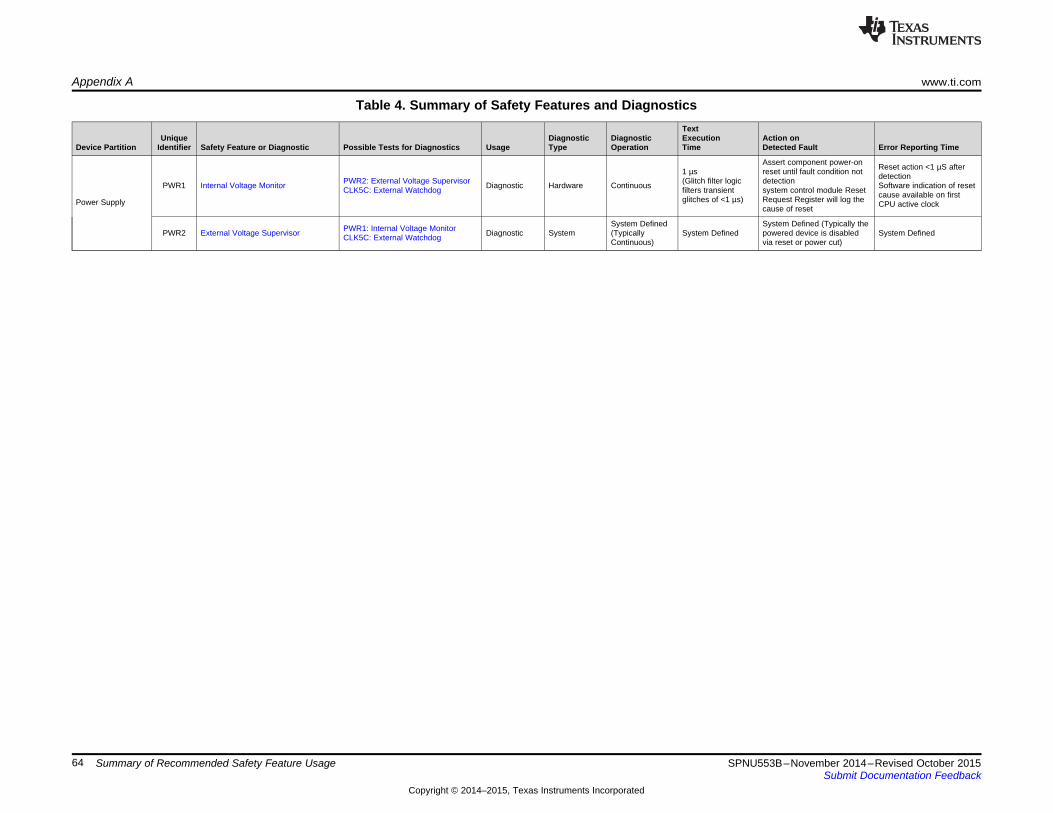
Appendix A www.ti.com
Table 4. Summary of Safety Features and DiagnosticsText
Unique Diagnostic Diagnostic Execution Action onDevice Partition Identifier Safety Feature or Diagnostic Possible Tests for Diagnostics Usage Type Operation Time Detected Fault Error Reporting Time
Assert component power-on Reset action <1 µS after1 µs reset until fault condition not detectionPWR2: External Voltage Supervisor (Glitch filter logic detectionPWR1 Internal Voltage Monitor Diagnostic Hardware Continuous Software indication of resetCLK5C: External Watchdog filters transient system control module Reset cause available on firstglitches of <1 µs) Request Register will log thePower Supply CPU active clockcause of reset
System Defined System Defined (Typically thePWR1: Internal Voltage MonitorPWR2 External Voltage Supervisor Diagnostic System (Typically System Defined powered device is disabled System DefinedCLK5C: External Watchdog Continuous) via reset or power cut)
64 Summary of Recommended Safety Feature Usage SPNU553B–November 2014–Revised October 2015Submit Documentation Feedback
Copyright © 2014–2015, Texas Instruments Incorporated
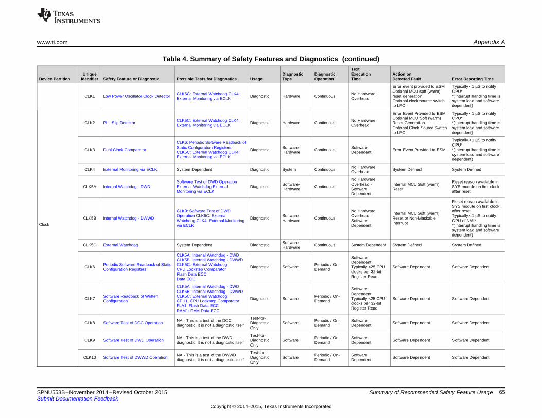
www.ti.com Appendix A
Table 4. Summary of Safety Features and Diagnostics (continued)Text
Unique Diagnostic Diagnostic Execution Action onDevice Partition Identifier Safety Feature or Diagnostic Possible Tests for Diagnostics Usage Type Operation Time Detected Fault Error Reporting Time
Error event provided to ESM Typically <1 µS to notifyOptional MCU soft (warm) CPU*CLK5C: External Watchdog CLK4: No HardwareCLK1 Low Power Oscillator Clock Detector Diagnostic Hardware Continuous reset generation *(Interrupt handling time isExternal Monitoring via ECLK Overhead Optional clock source switch system load and softwareto LPO dependent)
Error Event Provided to ESM Typically <1 µS to notifyOptional MCU Soft (warm) CPU*CLK5C: External Watchdog CLK4: No HardwareCLK2 PLL Slip Detector Diagnostic Hardware Continuous Reset Generation *(Interrupt handling time isExternal Monitoring via ECLK Overhead Optional Clock Source Switch system load and softwareto LPO dependent)
Typically <1 µS to notifyCLK6: Periodic Software Readback of CPU*Static Configuration Registers Software- SoftwareCLK3 Dual Clock Comparator Diagnostic Continuous Error Event Provided to ESM *(Interrupt handling time isCLK5C: External Watchdog CLK4: Hardware Dependent system load and softwareExternal Monitoring via ECLK dependent)
No HardwareCLK4 External Monitoring via ECLK System Dependent Diagnostic System Continuous System Defined System DefinedOverhead
No HardwareSoftware Test of DWD Operation Reset reason available inSoftware- Overhead - Internal MCU Soft (warm)CLK5A Internal Watchdog - DWD External Watchdog External Diagnostic Continuous SYS module on first clockHardware Software ResetMonitoring via ECLK after resetDependent
Reset reason available inSYS module on first clock
CLK9: Software Test of DWD No Hardware after resetInternal MCU Soft (warm)Operation CLK5C: External Software- Overhead - Typically <1 µS to notifyCLK5B Internal Watchdog - DWWD Diagnostic Continuous Reset or Non-MaskableWatchdog CLK4: External Monitoring Hardware Software CPU of NMI*InterruptClock via ECLK Dependent *(Interrupt handling time issystem load and softwaredependent)
Software-CLK5C External Watchdog System Dependent Diagnostic Continuous System Dependent System Defined System DefinedHardware
CLK5A: Internal Watchdog - DWD SoftwareCLK5B: Internal Watchdog - DWWD DependentPeriodic Software Readback of Static CLK5C: External Watchdog Periodic / On-CLK6 Diagnostic Software Typically <25 CPU Software Dependent Software DependentConfiguration Registers CPU Lockstep Comparator Demand clocks per 32-bitFlash Data ECC Register ReadData ECC
CLK5A: Internal Watchdog - DWD SoftwareCLK5B: Internal Watchdog - DWWD DependentSoftware Readback of Written CLK5C: External Watchdog Periodic / On-CLK7 Diagnostic Software Typically <25 CPU Software Dependent Software DependentConfiguration CPU1: CPU Lockstep Comparator Demand clocks per 32-bitFLA1: Flash Data ECC Register ReadRAM1: RAM Data ECC
Test-for-NA - This is a test of the DCC Periodic / On- SoftwareCLK8 Software Test of DCC Operation Diagnostic Software Software Dependent Software Dependentdiagnostic. It is not a diagnostic itself Demand DependentOnly
Test-for-NA - This is a test of the DWD Periodic / On- SoftwareCLK9 Software Test of DWD Operation Diagnostic Software Software Dependent Software Dependentdiagnostic. It is not a diagnostic itself Demand DependentOnly
Test-for-NA - This is a test of the DWWD Periodic / On- SoftwareCLK10 Software Test of DWWD Operation Diagnostic Software Software Dependent Software Dependentdiagnostic. It is not a diagnostic itself Demand DependentOnly
65SPNU553B–November 2014–Revised October 2015 Summary of Recommended Safety Feature UsageSubmit Documentation Feedback
Copyright © 2014–2015, Texas Instruments Incorporated

Appendix A www.ti.com
Table 4. Summary of Safety Features and Diagnostics (continued)Text
Unique Diagnostic Diagnostic Execution Action onDevice Partition Identifier Safety Feature or Diagnostic Possible Tests for Diagnostics Usage Type Operation Time Detected Fault Error Reporting Time
System Defined System Defined (Typically theRST1 External Monitoring of Warm Reset System Dependent Diagnostic System (Typically System Defined powered device is disabled System Defined
Continuous) via reset or power cut)
Software Check of Cause of Last Software - Periodic / On- SoftwareRST2 N/A Diagnostic N/A (Fault Avoidance) N/A (Fault Avoidance)Reset Hardware Demand Dependent
Software - Periodic / On- SoftwareRST3 Software Warm Reset Generation N/A Diagnostic N/A (Fault Avoidance) N/A (Fault Avoidance)Hardware Demand Dependent
1 µs(Glitch filter logicRST4 Glitch Filtering on Reset Pins N/A Diagnostic Hardware Continuous N/A (Fault Avoidance) N/A (Fault Avoidance)filters transientglitches of <1 µs
Software - Periodic / On- SoftwareRST5 Use of Status Shadow Registers N/A Diagnostic N/A (Fault Avoidance) N/A (Fault Avoidance)Hardware Demand Dependent
CLK5A: Internal Watchdog - DWD SoftwareCLK5B: Internal Watchdog - DWWDReset DependentPeriodic Software Readback of Static CLK5C: External Watchdog Periodic / On-RST6 Diagnostic Software Typically <25 CPU Software Dependent Software DependentConfiguration Registers CPU1: CPU Lockstep Comparator Demand clocks per 32-bitFLA1: Flash Data ECC Register ReadRAM1: RAM Data ECC
CLK5A: Internal Watchdog - DWD SoftwareCLK5B: Internal Watchdog - DWWD DependentSoftware Readback of Written CLK5C: External Watchdog Periodic / On-RST7 Diagnostic Software Typically <25 CPU Software Dependent Software DependentConfiguration CPU1: CPU Lockstep Comparator Demand clocks per 32-bitFLA1: Flash Data ECC Register ReadRAM1: RAM Data ECC
CLK5A: Internal Watchdog - DWD Software-CLK5B: Internal Watchdog - DWWD DependentCLK5C: External Watchdog Software - Periodic / On- HardwareRST8 Software Test for Reset Diagnostic Software Dependent Software DependentCPU1: CPU Lockstep Comparator Hardware Demand contribution to testFLA1: Flash Data ECC execution time isRAM1: RAM Data ECC negligible
Privileged Mode Access and Multi-Bit No HardwareSYS1 N/A Diagnostic Hardware Continuous Control Register not Updated N/A (Fault Avoidance)Enable Keys for Control Registers Overhead
CLK5A: Internal Watchdog - DWD SoftwareCLK5B: Internal Watchdog - DWWD DependentSoftware Readback of Written CLK5C: External Watchdog Periodic / On-SYS2 Diagnostic Software Typically <25 CPU Software Dependent Software DependentConfiguration CPU1: CPU Lockstep Comparator Demand clocks per 32-bitSystem Control FLA1: Flash Data ECC Register ReadModule RAM1: RAM Data ECC
CLK5A: Internal Watchdog - DWD SoftwareCLK5B: Internal Watchdog - DWWD DependentPeriodic Software Readback of Static CLK5C: External Watchdog Periodic / On-SYS3 Diagnostic Software Typically <25 CPU Software Dependent Software DependentConfiguration Registers CPU1: CPU Lockstep Comparator Demand clocks per 32-bitFLA1: Flash Data ECC Register ReadRAM1: RAM Data ECC
66 Summary of Recommended Safety Feature Usage SPNU553B–November 2014–Revised October 2015Submit Documentation Feedback
Copyright © 2014–2015, Texas Instruments Incorporated

www.ti.com Appendix A
Table 4. Summary of Safety Features and Diagnostics (continued)Text
Unique Diagnostic Diagnostic Execution Action onDevice Partition Identifier Safety Feature or Diagnostic Possible Tests for Diagnostics Usage Type Operation Time Detected Fault Error Reporting Time
CLK5A: Internal Watchdog - DWD SoftwareCLK5B: Internal Watchdog - DWWD DependentPeriodic Software Readback of Static CLK5C: External Watchdog Periodic / On-ESM1 Diagnostic Software Typically <25 CPU Software Dependent Software DependentConfiguration Registers CPU1: CPU Lockstep Comparator Demand clocks per 32-bitFLA1: Flash Data ECC Register ReadRAM1: RAM Data ECC
CLK5A: Internal Watchdog - DWD Software-CLK5B: Internal Watchdog - DWWD Dependent
Boot Time Software Test of Error CLK5C: External Watchdog Software - Periodic / On- HardwareESM2A Diagnostic Software Dependent Software DependentPath Reporting CPU1: CPU Lockstep Comparator Hardware Demand contribution to testFLA1: Flash Data ECC execution time isRAM1: RAM Data ECC negligible
Error Signaling CLK5A: Internal Watchdog - DWD Software-Module CLK5B: Internal Watchdog - DWWD Dependent(ESM) Periodic Software Test of Error Path CLK5C: External Watchdog Software - Periodic / On- HardwareESM2B Diagnostic Software Dependent Software DependentReporting CPU1: CPU Lockstep Comparator Hardware Demand contribution to testFLA1: Flash Data ECC execution time isRAM1: RAM Data ECC negligible
N/A - FaultESM3 Use of Status Shadow Registers N/A Diagnostic Hardware Continuous N/A - Fault Avoidance N/A - Fault AvoidanceAvoidance
CLK5A: Internal Watchdog - DWD SoftwareCLK5B: Internal Watchdog - DWWD DependentSoftware Readback of Written CLK5C: External Watchdog Periodic / On-ESM4 Diagnostic Software Typically <25 CPU Software Dependent Software DependentConfiguration CPU1: CPU Lockstep Comparator Demand clocks per 32-bitFLA1: Flash Data ECC Register ReadRAM1: RAM Data ECC
67SPNU553B–November 2014–Revised October 2015 Summary of Recommended Safety Feature UsageSubmit Documentation Feedback
Copyright © 2014–2015, Texas Instruments Incorporated

Appendix A www.ti.com
Table 4. Summary of Safety Features and Diagnostics (continued)Text
Unique Diagnostic Diagnostic Execution Action onDevice Partition Identifier Safety Feature or Diagnostic Possible Tests for Diagnostics Usage Type Operation Time Detected Fault Error Reporting Time
Typically <1 µsLockstep Comparator (CCM) SelfCPU1 CPU Lockstep Comparator Diagnostic Hardware Continuous 2 CPU Cycles ESM Error (implementationTest dependent)
CPU1: CPU Lockstep Comparator, Device Dependent Typically <1 µsPeriodic / On-CPU2A Boot Time Execution of LBIST STC CLK4: External Watchdog, CPU9: Diagnostic Hardware (see the device- Error Flag Asserted (implementationDemandLBIST Auto-Coverage specific data sheet) dependent)
CPU1: CPU Lockstep Comparator, Device Dependent Typically <1 µsPeriodic / On-CPU2B Periodic Execution of LBIST STC CLK4: External Watchdog, CPU9: Diagnostic Hardware (see the device- Error Flag Asserted (implementationDemandLBIST Auto-Coverage specific data sheet) dependent)
CPU1: CPU Lockstep Comparator,CPU2A: Boot Time Execution of No Hardware 1 CPU Cycle AfterCPU3 Memory Protection Unit (MPU) Diagnostic Hardware Continuous Instruction Abort/Data AbortLBIST STC, CPU2B: Periodic Overhead DetectionExecution of LBIST STC
CPU1: CPU Lockstep Comparator,CPU2A: Boot Time Execution of Software- SoftwareCPU4 Online Profiling Using PMU Diagnostic Continuous Software Defined Software-DependentLBIST STC, CPU2B: Periodic Hardware DependentExecution of LBIST STC
CPU1: CPU Lockstep Comparator,Cortex-R4 CentralCPU Illegal Operation and Instruction CPU2A: Boot Time Execution of No Hardware 1 CPU Cycle AfterProcessing Unit CPU5 Diagnostic Hardware Continuous Instruction Abort/Data AbortTrapping LBIST STC, CPU2B: Periodic Overhead Detection(CPU)
Execution of LBIST STC
CLK5A: Internal Watchdog - DWD SoftwareCLK5B: Internal Watchdog - DWWD DependentPeriodic Software Readback of Static CLK5C: External Watchdog Periodic / On-CPU6 Diagnostic Software Typically <25 CPU Software Dependent Software DependentConfiguration Registers CPU1: CPU Lockstep Comparator Demand clocks per 32-bitFLA1: Flash Data ECC Register ReadRAM1: RAM Data ECC
SoftwareCPU1: CPU Lockstep Comparator, DependentSoftware Read Back of CPU CPU2A: Boot Time Execution of Periodic / On-CPU7 Diagnostic Software Typically <25 CPU Software Dependent Software DependentRegisters LBIST STC, CPU2B: Periodic Demand clocks per 32-bitExecution of LBIST STC Register Read
Test-for- Device Dependent Typically <1 µsLockstep Comparator (CCM) Self NA - This is a test of the CCM Periodic / On-CPU8 Diagnostic Hardware (see the device- Error Flag Asserted (implementationTest diagnostic,. It is not a diagnostic itself DemandOnly specific data sheet) dependent)
Test-for-NA - This is a test of the LBIST Periodic / On- N/A; implicit inCPU9 LBIST Auto-Coverage Diagnostic Hardware N/A N/Adiagnostic. It is not a diagnostic itself Demand LBIST operationOnly
68 Summary of Recommended Safety Feature Usage SPNU553B–November 2014–Revised October 2015Submit Documentation Feedback
Copyright © 2014–2015, Texas Instruments Incorporated

www.ti.com Appendix A
Table 4. Summary of Safety Features and Diagnostics (continued)Text
Unique Diagnostic Diagnostic Execution Action onDevice Partition Identifier Safety Feature or Diagnostic Possible Tests for Diagnostics Usage Type Operation Time Detected Fault Error Reporting Time
CPU1: CPU Lockstep ComparatorFLA10: Flash Wrapper Diag Mode 5 No Hardware Same CPU clock cycles asFLA1 Flash Data ECC Diagnostic Hardware Continuous CPU Abort / ESM EventTest Overhead data usedFLA11: Flash Wrapper Diag Mode 7
No HardwareFLA2 Hard Error Cache and Livelock CPU Lockstep Comparator Diagnostic Hardware Continuous Live lock / ESM Event Typically <1 µsOverhead
FLA10: Flash Wrapper Diag Mode 5 No Hardware Same CPU clock cycles asFLA3 Flash Wrapper Address ECC Test Diagnostic Hardware Continuous CPU Abort / ESM EventOverhead data usedFLA11: Flash Wrapper Diag Mode 7
Software Readback of Written No Hardware Same CPU clock cycles asFLA4 Address and Control Parity Configuration Diagnostic Hardware Continuous CPU Bus ErrorOverhead data usedSoftware Test of Parity Logic
Depends on size ofmemory under test.External Watchdog One 64-bit word perSoftware Readback of WrittenBoot Time Check of Flash Memory Software - clock cycle plusFLA5A Configuration Diagnostic On Demand Software Defined Software DependentContents by Hardware CRC Hardware overhead.Software Test of Hardware CRC Overhead isCRC Auto-Coverage softwaredependent.
Depends on size ofmemory under test.External Watchdog One 64-bit word perSoftware Readback of WrittenPeriodic Check of Flash Memory Software - clock cycle plusFLA5B Configuration Diagnostic On Demand Software Defined Software DependentContents by Hardware CRC Hardware overhead.Software Test of Hardware CRC Overhead isCRC Auto-CoveragePrimary Flash and software
Level 1 (L1) dependent.Interconnect
Bit Multiplexing in Flash Memory N/A - FaultFLA6 N/A - Fault Avoidance Diagnostic Hardware Continuous N/A - Fault Avoidance N/A - Fault AvoidanceArray Avoidance
Software Test of Flash Sector No Hardware Software dependent basedFLA7 Flash Sector Protection Diagnostic Hardware Continuous Flash Programing BlockedProtection Logic Overhead on readback of content
CLK5A: Internal Watchdog - DWD SoftwareCLK5B: Internal Watchdog - DWWD DependentPeriodic Software Readback of Static CLK5C: External Watchdog Periodic / On-FLA8 Diagnostic Software Typically <25 CPU Software Dependent Software DependentConfiguration Registers CPU1: CPU Lockstep Comparator Demand clocks per 32-bitFLA1: Flash Data ECC Register ReadRAM1: RAM Data ECC
CLK5A: Internal Watchdog - DWD SoftwareCLK5B: Internal Watchdog - DWWD DependentSoftware Readback of Written CLK5C: External Watchdog Periodic / On-FLA9 Diagnostic Software Typically <25 CPU Software Dependent Software DependentConfiguration CPU1: CPU Lockstep Comparator Demand clocks per 32-bitFLA1: Flash Data ECC Register ReadRAM1: RAM Data ECC
SoftwareTest-for- DependentNA - this is a test of a diagnostic. It is Software -FLA10 Flash Wrapper Diag Mode 5 Test Diagnostic On Demand Typically <1 µs Software Dependent Software Dependentnot a diagnostic itself HardwareOnly overhead due to
hardware
SoftwareTest-for- DependentNA - this is a test of a diagnostic. It is Software -FLA11 Flash Wrapper Diag Mode 7 Diagnostic On Demand Typically <1 µs Software Dependent Software Dependentnot a diagnostic itself HardwareOnly overhead due to
hardware
69SPNU553B–November 2014–Revised October 2015 Summary of Recommended Safety Feature UsageSubmit Documentation Feedback
Copyright © 2014–2015, Texas Instruments Incorporated

Appendix A www.ti.com
Table 4. Summary of Safety Features and Diagnostics (continued)Text
Unique Diagnostic Diagnostic Execution Action onDevice Partition Identifier Safety Feature or Diagnostic Possible Tests for Diagnostics Usage Type Operation Time Detected Fault Error Reporting Time
Test-for-NA - This is a test of the parity SoftwareFLA12 Software Test of Parity Logic Diagnostic Software On Demand Software Dependent Software Dependentdiagnostic. It is not a diagnostic itself DependentOnly
NA - This is a test of the flash sector Test-for-Software Test of Flash Sector SoftwareFLA13 protection logic diagnostic. It is not a Diagnostic Software On Demand Software Dependent Software DependentProtection Logic Dependentdiagnostic itself Only
Depends on size ofPrimary Flash andmemory under test.Level 1 (L1)
NA - This is a test of the hardware Test-for- One 64-bit word perInterconnect Software - Periodic / On-FLA14 Software Test of Hardware CRC CRC diagnostic. It is not a diagnostic Diagnostic clock cycle plus Software Dependent Software DependentHardware Demanditself Only overhead.Overhead issoftware dependent
NA - This is a test of the hardware Test-for- Periodic / On- N/A; implicit in CRCFLA15 CRC Auto-Coverage CRC diagnostic. It is not a diagnostic Diagnostic Hardware N/A N/ADemand operationitself Only
70 Summary of Recommended Safety Feature Usage SPNU553B–November 2014–Revised October 2015Submit Documentation Feedback
Copyright © 2014–2015, Texas Instruments Incorporated

www.ti.com Appendix A
Table 4. Summary of Safety Features and Diagnostics (continued)Text
Unique Diagnostic Diagnostic Execution Action onDevice Partition Identifier Safety Feature or Diagnostic Possible Tests for Diagnostics Usage Type Operation Time Detected Fault Error Reporting Time
CPU Lockstep ComparatorFlash Wrapper Diag Mode 1 Test No Overhead Same CPU clock cycles asFEE1 FEE Data ECC Flash Wrapper Diag Mode 2 Test Diagnostic Hardware Continuous ESM Event(Same clock cycle) data usedFlash Wrapper Diag Mode 3 TestFlash Wrapper Diag Mode 4 Test
Depends on size ofmemory under test.Software Readback of Written One 64-bit word perConfigurationBoot Time Check of FEE Memory Software - clock cycle plusFEE2A Software Test of Hardware CRC Diagnostic On Demand Software Defined Software DependentContents by Hardware CRC Hardware overhead.CRC Auto-Coverage Overhead isExternal Watchdog softwaredependent.
Depends on size ofmemory under test.Software Readback of Written One 64-bit word perConfigurationPeriodic Check of FEE Memory Software - clock cycle plusFEE2B Software Test of Hardware CRC Diagnostic On Demand Software Defined Software DependentContents by Hardware CRC Hardware overhead.CRC Auto-Coverage Overhead isExternal Watchdog softwaredependent.
N/A - FaultFlash EEPROM FEE3 Bit Multiplexing in FEE Array N/A - Fault Avoidance Diagnostic Hardware Continuous N/A - Fault Avoidance N/A - Fault AvoidanceAvoidanceEmulation(FEE) Periodic Check of FEE Memory
Contents by Hardware CRC No Overhead Software dependent basedFEE4 FEE Sector Protection Diagnostic Hardware Continuous Flash Programing BlockedSoftware Test of Flash Sector (Same clock cycle) on readback of contentProtection Logic
Internal Watchdog - DWD SoftwareInternal Watchdog - DWWD DependentPeriodic Software Readback of Static External Watchdog Periodic / On-FEE5 Diagnostic Software Typically <25 CPU Software Dependent Software DependentConfiguration Registers CPU Lockstep Comparator Demand clocks per 32-bitFlash Data ECC Register ReadData ECC
CLK5A: Internal Watchdog - DWD SoftwareCLK5B: Internal Watchdog - DWWD DependentSoftware Readback of Written CLK5C: External Watchdog Periodic / On-FEE6 Diagnostic Software Typically <25 CPU Software Dependent Software DependentConfiguration CPU1: CPU Lockstep Comparator Demand clocks per 32-bitFLA1: Flash Data ECC Register ReadRAM1: RAM Data ECC
Periodic Check of FEE MemoryContents by Hardware CRCFlash Wrapper Diag Mode 1 Test No Hardware Same CPU clock cycles asFEE7 Flash Wrapper Address ECC Diagnostic Hardware Continuous ESM EventFlash Wrapper Diag Mode 2 Test Overhead data usedFlash Wrapper Diag Mode 3 TestFlash Wrapper Diag Mode 4 Test
71SPNU553B–November 2014–Revised October 2015 Summary of Recommended Safety Feature UsageSubmit Documentation Feedback
Copyright © 2014–2015, Texas Instruments Incorporated

Appendix A www.ti.com
Table 4. Summary of Safety Features and Diagnostics (continued)Text
Unique Diagnostic Diagnostic Execution Action onDevice Partition Identifier Safety Feature or Diagnostic Possible Tests for Diagnostics Usage Type Operation Time Detected Fault Error Reporting Time
SoftwareDependentNA - this is a test of a diagnostic. It is Test for Software -FEE8 Flash Wrapper Diag Mode 1 Test On Demand Typically <1 µs Software Dependent Software Dependentnot a diagnostic itself Diagnostic Hardware overhead due tohardware
SoftwareDependentNA - this is a test of a diagnostic. It is Test for Software -FEE9 Flash Wrapper Diag Mode 2 Test On Demand Typically <1 µs Software Dependent Software Dependentnot a diagnostic itself Diagnostic Hardware overhead due tohardware
SoftwareDependentNA - this is a test of a diagnostic. It is Test for Software -FEE10 Flash Wrapper Diag Mode 3 Test On Demand Typically <1 µs Software Dependent Software Dependentnot a diagnostic itself Diagnostic Hardware overhead due tohardware
SoftwareFlash Emulated DependentEEPROM NA - this is a test of a diagnostic. It is Test for Software -FEE11 Flash Wrapper Diag Mode 4 Test On Demand Typically <1 µs Software Dependent Software Dependent(FEE) not a diagnostic itself Diagnostic Hardware overhead due tohardware
NA -This is a test of the flash sectorSoftware Test of Flash Sector Test for Software-FEE12 protection logic diagnostic. It is not a Software On Demand Software Dependent Software DependentProtection Logic Diagnostic Dependentdiagnostic itself
Depends on size ofmemory under test.One 64-bit word perNA - This is a test of the hardware Test-for- Software - Periodic / On- clock cycle plusFEE13 Software Test of Hardware CRC CRC diagnostic. It is not a diagnostic Software Dependent Software DependentDiagnostic Hardware Demand overhead.itself Overhead issoftwaredependent.
NA - This is a test of the hardware Test-for- Periodic / On- N/A; implicit in CRCFEE14 CRC Auto-Coverage CRC diagnostic. It is not a diagnostic Diagnostic Hardware N/A N/ADemand operationitself Only
72 Summary of Recommended Safety Feature Usage SPNU553B–November 2014–Revised October 2015Submit Documentation Feedback
Copyright © 2014–2015, Texas Instruments Incorporated

www.ti.com Appendix A
Table 4. Summary of Safety Features and Diagnostics (continued)Text
Unique Diagnostic Diagnostic Execution Action onDevice Partition Identifier Safety Feature or Diagnostic Possible Tests for Diagnostics Usage Type Operation Time Detected Fault Error Reporting Time
No Hardware Same CPU clock cycles asRAM1 Data ECC CPU Lockstep Comparator Diagnostic Hardware Continuous CPU Abort / ESM EventOverhead data used
No HardwareRAM2 Hard Error Cache and Livelock CPU Lockstep Comparator Diagnostic Hardware Continuous Live lock / ESM Event Typically <1usOverhead
Software / SoftwareRAM3 Correctable ECC Profiling Software Test of ECC Profiler Diagnostic Continuous Software Dependent Software DependentHardware Dependent
Software Readback of Written No Hardware Same CPU clock cycles asRAM4 Address and Control Bus Parity Configuration Diagnostic Hardware Continuous CPU Bus ErrorOverhead data usedSoftware Test of Parity Logic
No Hardware Same CPU clock cycles asRAM5 Redundant Address Decode Redundant Address Decode Self Test Diagnostic Hardware Continuous CPU Bus ErrorOverhead data used
Data and ECC Storage in Multiple N/A (FaultRAM6 N/A - Fault Avoidance Diagnostic Hardware Continuous N/A (Fault Avoidance) N/A (Fault Avoidance)Physical Banks Avoidance)
Data ECCSoftware Readback of WrittenConfiguration Device DependentBoot Time PBIST Check of Primary Software Test of PBIST Periodic / On-RAM7A Diagnostic Hardware (see the device- Flag Set in Error Register Software DependentSRAM PBIST Auto-Coverage Demand specific data sheet)CPU Lockstep ComparatorExternal WatchdogFlash Data ECC
Data ECCSoftware Readback of WrittenConfigurationSRAM and Level 1 Device DependentPeriodic PBIST Check of Primary Software Test of PBIST Periodic / On-(L1) RAM7B Diagnostic Hardware (see the device- Flag Set in Error Register Software DependentSRAM PBIST Auto-Coverage DemandInterconnect specific data sheet)CPU Lockstep ComparatorExternal WatchdogFlash Data ECC
Bit Multiplexing in Primary SRAM N/A (FaultRAM8 N/A - Fault Avoidance Diagnostic Hardware Continuous N/A (Fault Avoidance) N/A (Fault Avoidance)Array Avoidance)
Depends on size ofmemory under test.
Software Readback of Written One 64-bit word perPeriodic Hardware CRC Check of Configuration, Software Test of Software / Periodic / On- clock cycle plusRAM9 Diagnostic Software Dependent Software DependentPrimary SRAM Contents Hardware CRC, CRC Auto-Coverage, Hardware Demand overhead.
External Watchdog Overhead issoftwaredependent.
CLK5A: Internal Watchdog - DWD SoftwareCLK5B: Internal Watchdog - DWWD DependentPeriodic Software Readback of Static CLK5C: External Watchdog Periodic / On-RAM10 Diagnostic Software Typically <25 CPU Software Dependent Software DependentConfiguration Registers CPU1: CPU Lockstep Comparator Demand clocks per 32-bitFLA1: Flash Data ECC Register ReadRAM1: RAM Data ECC
CLK5A: Internal Watchdog - DWD SoftwareCLK5B: Internal Watchdog - DWWD DependentSoftware Readback of Written CLK5C: External Watchdog Periodic / On-RAM11 Diagnostic Software Typically <25 CPU Software Dependent Software DependentConfiguration CPU1: CPU Lockstep Comparator Demand clocks per 32-bitFLA1: Flash Data ECC Register ReadRAM1: RAM Data ECC
73SPNU553B–November 2014–Revised October 2015 Summary of Recommended Safety Feature UsageSubmit Documentation Feedback
Copyright © 2014–2015, Texas Instruments Incorporated

Appendix A www.ti.com
Table 4. Summary of Safety Features and Diagnostics (continued)Text
Unique Diagnostic Diagnostic Execution Action onDevice Partition Identifier Safety Feature or Diagnostic Possible Tests for Diagnostics Usage Type Operation Time Detected Fault Error Reporting Time
Software Test of SRAM Wrapper N/A - This is a test of Redundant Test-for- Periodic / On- SoftwareRAM12 Redundant Address Decode and Address Decode and ECC. It is not a Diagnostic Software Software Dependent Software DependentDemand DependentECC diagnostic itself Only
Test-for-N/A - This is a test of the parity logic. Periodic / On- SoftwareRAM13 Software Test of Parity Logic Diagnostic Software Software Dependent Software DependentIt is not a diagnostic itself Demand DependentOnly
Test-for-NA - This is a test of the PBIST Periodic / On- SoftwareRAM14 Software Test of PBIST Diagnostic Software Software Dependent Software Dependentdiagnostic. It is not a diagnostic itself Demand DependentOnly
Test-for-NA - This is a test of the PBIST Periodic / On- N/A; implicit inRAM15 PBIST Auto-Coverage Diagnostic Hardware N/A N/Adiagnostic. It is not a diagnostic itself Demand PBIST operationOnly
Test-for-NA - This is a test of the ECC profiler Periodic / On- SoftwareSRAM and Level 1 RAM16 Software Test of ECC Profiler Diagnostic Software Software Dependent Software Dependentdiagnostic. It is not a diagnostic itself Demand Dependent(L1) OnlyInterconnect
Test-for-NA - This is a test of the PBIST Periodic / On- No OverheadRAM17 Redundant Address Decode Self Test Diagnostic Hardware Software Dependent Software Dependentdiagnostic. It is not a diagnostic itself Demand (Same clock cycle)Only
Depends on size ofmemory under test.One 64-bit word perNA - This is a test of the hardware Test-for- Software / Periodic / On- clock cycle plusRAM18 Software Test of Hardware CRC CRC diagnostic. It is not a diagnostic Diagnostic Software Dependent Software DependentHardware Demand overhead.itself Only Overhead issoftwaredependent.
NA - This is a test of the hardware Test-for- Periodic / On- N/A; implicit in CRCRAM19 CRC Auto-Coverage CRC diagnostic. It is not a diagnostic Diagnostic Hardware N/A N/ADemand operationitself Only
74 Summary of Recommended Safety Feature Usage SPNU553B–November 2014–Revised October 2015Submit Documentation Feedback
Copyright © 2014–2015, Texas Instruments Incorporated

www.ti.com Appendix A
Table 4. Summary of Safety Features and Diagnostics (continued)Text
Unique Diagnostic Diagnostic Execution Action onDevice Partition Identifier Safety Feature or Diagnostic Possible Tests for Diagnostics Usage Type Operation Time Detected Fault Error Reporting Time
Boot Time Software Test of Basic Bus master notificationError Trapping (Including Peripheral Functionality Including Error Tests No HardwareINC1 Diagnostic Hardware Continuous Bus Error typically <10 clock cyclesSlave Error Trapping) Periodic Software Test of Basic Overhead after fault detectionFunctionality Including Error Tests
Boot Time Software Test of Basic Bus master notificationFunctionality Including Error Tests No HardwareINC2 PCR Access Management Diagnostic Hardware Continuous Bus Error typically <10 clock cyclesPeriodic Software Test of Basic Overhead after fault detectionFunctionality Including Error Tests
CLK5A: Internal Watchdog - DWDCLK5B: Internal Watchdog - DWWDCLK5C: External Watchdog Periodic / On- SoftwareINC3 Information Redundancy Diagnostic Software Software Dependent Software DependentCPU1: CPU Lockstep Comparator Demand DependentFLA1: Flash Data ECCRAM1: RAM Data ECC
CLK5A: Internal Watchdog - DWD SoftwareCLK5B: Internal Watchdog - DWWD DependentPeriodic Software Readback of Static CLK5C: External Watchdog Periodic / On-INC4 Diagnostic Software Typically <25 CPU Software Dependent Software DependentConfiguration Registers CPU1: CPU Lockstep Comparator Demand clocks per 32-bitFLA1: Flash Data ECC Register ReadRAM1: RAM Data ECCLevel 2 and CLK5A: Internal Watchdog - DWD Software-Level 3 CLK5B: Internal Watchdog - DWWD Dependent(L2 and L3) Boot Time Software Test of Basic CLK5C: External Watchdog Software - Periodic / On- HardwareINC5A Diagnostic Software Dependent Software DependentInterconnect Functionality Including Error Tests CPU1: CPU Lockstep Comparator Hardware Demand contribution to test
FLA1: Flash Data ECC execution time isRAM1: RAM Data ECC negligible
CLK5A: Internal Watchdog - DWD Software-CLK5B: Internal Watchdog - DWWD Dependent
Periodic Software Test of Basic CLK5C: External Watchdog Software - Periodic / On- HardwareINC5B Diagnostic Software Dependent Software DependentFunctionality Including Error Tests CPU1: CPU Lockstep Comparator Hardware Demand contribution to testFLA1: Flash Data ECC execution time isRAM1: RAM Data ECC negligible
CLK5A: Internal Watchdog - DWD SoftwareCLK5B: Internal Watchdog - DWWD DependentSoftware Readback of Written CLK5C: External Watchdog Periodic / On-INC6 Diagnostic Software Typically <25 CPU Software Dependent Software DependentConfiguration CPU1: CPU Lockstep Comparator Demand clocks per 32-bitFLA1: Flash Data ECC Register ReadRAM1: RAM Data ECC
CLK5A: Internal Watchdog - DWDCLK5B: Internal Watchdog - DWWDCLK5C: External Watchdog Periodic / On-INC7 Transmission Redundancy Diagnostic Software System Dependent System Dependent System DependentCPU1: CPU Lockstep Comparator DemandFLA1: Flash Data ECCRAM1: RAM Data ECC
75SPNU553B–November 2014–Revised October 2015 Summary of Recommended Safety Feature UsageSubmit Documentation Feedback
Copyright © 2014–2015, Texas Instruments Incorporated

Appendix A www.ti.com
Table 4. Summary of Safety Features and Diagnostics (continued)Text
Unique Diagnostic Diagnostic Execution Action onDevice Partition Identifier Safety Feature or Diagnostic Possible Tests for Diagnostics Usage Type Operation Time Detected Fault Error Reporting Time
Continuous Device Dependent No Overhead (Available onEFU1 Boot Time Autoload Self Test Autoload Self Test Auto-Coverage Diagnostic Hardware (Every power-on (see the device- ESM Event 1st CPU clock cycle after
reset operation) specific data sheet) release of reset)
No Hardware Same CPU clock cycle asEFU2 E-Fuse ECC EFuse ECC Logic Self Test Diagnostic Hardware Continuous ESM EventOverhead data is used
CLK5A: Internal Watchdog - DWD SoftwareCLK5B: Internal Watchdog - DWWD DependentPeriodic Software Readback of Static CLK5C: External Watchdog Periodic / On-EFU3 Diagnostic Software Typically <25 CPU Software Dependent Software DependentConfiguration Registers CPU1: CPU Lockstep Comparator Demand clocks per 32-bitFLA1: Flash Data ECC Register ReadRAM1: RAM Data ECCEFuseStatic CLK5A: Internal Watchdog - DWD SoftwareConfiguration CLK5B: Internal Watchdog - DWWD DependentSoftware Readback of Written CLK5C: External Watchdog Periodic / On-EFU4 Diagnostic Software Typically <25 CPU Software Dependent Software DependentConfiguration CPU1: CPU Lockstep Comparator Demand clocks per 32-bitFLA1: Flash Data ECC Register ReadRAM1: RAM Data ECC
NA - This is a test of the Efuse Device Dependent No Overhead (Available onTest- for-EFU5 Autoload Self Test Auto-Coverage autoload diagnostic. It is not a Hardware At Boot Time (see the device- ESM Event 1st CPU clock cycle afterDiagnosticdiagnostic itself specific data sheet) release of reset)
NA - This is a test of the Efuse ECC Test-for- Software - No HardwareEFU6 EFuse ECC Logic Self Test logic through self test diagnostic. It is On Demand ESM Event No OverheadDiagnostic Hardware Overheadnot a diagnostic itself
76 Summary of Recommended Safety Feature Usage SPNU553B–November 2014–Revised October 2015Submit Documentation Feedback
Copyright © 2014–2015, Texas Instruments Incorporated

www.ti.com Appendix A
Table 4. Summary of Safety Features and Diagnostics (continued)Text
Unique Diagnostic Diagnostic Execution Action onDevice Partition Identifier Safety Feature or Diagnostic Possible Tests for Diagnostics Usage Type Operation Time Detected Fault Error Reporting Time
CPU Lockstep Comparator, FlashWrapper Diag Mode 1 Test, Flash No Hardware Same CPU clock cycle asOTP1 OTP ECC Wrapper Diag Mode 2 Test, Flash Diagnostic Hardware Continuous ESM EventOverhead data usedWrapper Diag Mode 3 Test, FlashWrapper Diag Mode 4 Test
CLK5A: Internal Watchdog - DWD SoftwareCLK5B: Internal Watchdog - DWWD DependentPeriodic Software Readback of Static CLK5C: External Watchdog Periodic / On-OTP2 Diagnostic Software Typically <25 CPU Software Dependent Software DependentConfiguration Registers CPU1: CPU Lockstep Comparator Demand clocks per 32-bitFLA1: Flash Data ECC Register ReadRAM1: RAM Data ECC
CLK5A: Internal Watchdog - DWD SoftwareCLK5B: Internal Watchdog - DWWD DependentSoftware Readback of Written CLK5C: External Watchdog Periodic / On-OTP3 Diagnostic Software Typically <25 CPU Software Dependent Software DependentConfiguration CPU1: CPU Lockstep Comparator Demand clocks per 32-bitFLA1: Flash Data ECC Register ReadRAM1: RAM Data ECC
Depends on size ofmemory under test.
Software Readback of Written One 64-bit word perBoot Time Hardware CRC Check of Configuration, Software Test of Software - Periodic / On- clock cycle plusOTP4A Diagnostic Software Dependent Software DependentOTP Contents Hardware CRC, CRC Auto-Coverage, Hardware Demand overhead.
External Watchdog Overhead issoftwaredependent.One Time
Programmable Depends on size of(OTP) memory under test.Flash Static Software Readback of Written One 64-bit word perConfiguration Periodic Hardware CRC Check of Configuration, Software Test of Software - Periodic / On- clock cycle plusOTP4B Diagnostic Software Dependent Software DependentOTP Contents Hardware CRC, CRC Auto-Coverage, Hardware Demand overhead.
External Watchdog Overhead issoftwaredependent.
Bit Multiplexing in Flash Memory N/A - FaultOTP5 N/A - Fault Avoidance Diagnostic Hardware Continuous N/A - Fault Avoidance N/A - Fault AvoidanceArray Avoidance
Software Test of Flash Sector No HardwareOTP6 Flash Sector Protection Diagnostic Hardware Continuous Flash Programming Blocked Software DependentProtection Logic Overhead
SoftwareTest-for- DependentN/A - This is a test of a diagnostic. It Software - Periodic / On-OTP7 Flash Wrapper Diag Mode 1 Test Diagnostic Typically <1 µs Software Dependent Software Dependentis not a diagnostic itself Hardware DemandOnly overhead due to
hardware
SoftwareTest-for- DependentN/A - This is a test of a diagnostic. It Software - Periodic / On-OTP8 Flash Wrapper Diag Mode 2 Test Diagnostic Typically <1 µs Software Dependent Software Dependentis not a diagnostic itself Hardware DemandOnly overhead due to
hardware
SoftwareTest-for- DependentN/A - This is a test of a diagnostic. It Software - Periodic / On-OTP9 Flash Wrapper Diag Mode 3 Test Diagnostic Typically <1 µs Software Dependent Software Dependentis not a diagnostic itself Hardware DemandOnly overhead due to
hardware
77SPNU553B–November 2014–Revised October 2015 Summary of Recommended Safety Feature UsageSubmit Documentation Feedback
Copyright © 2014–2015, Texas Instruments Incorporated

Appendix A www.ti.com
Table 4. Summary of Safety Features and Diagnostics (continued)Text
Unique Diagnostic Diagnostic Execution Action onDevice Partition Identifier Safety Feature or Diagnostic Possible Tests for Diagnostics Usage Type Operation Time Detected Fault Error Reporting Time
SoftwareTest-for- DependentN/A - This is a test of a diagnostic. It Software - Periodic / On-OTP10 Flash Wrapper Diag Mode 4 Test Diagnostic Typically <1 µs Software Dependent Software Dependentis not a diagnostic itself Hardware DemandOnly overhead due to
hardware
NA - This is a test of the flash sector Test-for-Software Test of Flash Sector Periodic / On- SoftwareOTP11 protection logic diagnostic. It is not a Diagnostic Software Software Dependent Software DependentProtection Logic Demand Dependentdiagnostic itself OnlyOne TimeProgrammable Depends on size of(OTP) memory under test.Flash Static One 64-bit word perNA - This is a test of the hardware Test-for-Configuration Software - Periodic / On- clock cycle plusOTP12 Software Test of Hardware CRC CRC diagnostic. It is not a diagnostic Diagnostic Software Dependent Software DependentHardware Demand overhead.itself Only Overhead is
softwaredependent.
NA - This is a test of the hardware Test-for- Periodic / On- N/A; implicit in CRCOTP13 CRC Auto-Coverage CRC diagnostic. It is not a diagnostic Diagnostic Hardware N/A N/ADemand operationitself Only
HardwareLocking Mechanism For Control No HardwareIOM1 N/A Diagnostic (Fault Continuous N/A (Fault Avoidance) N/A (Fault Avoidance)Registers OverheadAvoidance)
Hardware Periodic / On- No HardwareIOM2 Master ID Filtering N/A Diagnostic (Fault N/A (Fault Avoidance) N/A (Fault Avoidance)Demand OverheadAvoidance)
CLK5A: Internal Watchdog - DWDCLK5B: Internal Watchdog - DWWD Bus master notificationCLK5C: External Watchdog Periodic / On- No HardwareIOM3 Error Trapping Diagnostic Hardware Bus Error typically <10 clock cyclesCPU1: CPU Lockstep Comparator Demand Overhead after fault detectionFLA1: Flash Data ECCRAM1: RAM Data ECC
CLK5A: Internal Watchdog - DWD SoftwareCLK5B: Internal Watchdog - DWWD DependentPeriodic Software Readback of Static CLK5C: External Watchdog Periodic / On-IOM4 Diagnostic Software Typically <25 CPU Software Dependent Software DependentConfiguration Registers CPU1: CPU Lockstep Comparator Demand clocks per 32-bitFLA1: Flash Data ECCInput/Output (I/O) Register ReadRAM1: RAM Data ECCMultiplexing Module(IOMM) CLK5A: Internal Watchdog - DWD
CLK5B: Internal Watchdog - DWWDBoot Time Software Test of Function CLK5C: External Watchdog Software - Periodic / On- SoftwareIOM5A Diagnostic Software Dependent Software DependentUsing I/O Loopback CPU1: CPU Lockstep Comparator Hardware Demand Dependent
FLA1: Flash Data ECCRAM1: RAM Data ECC
CLK5A: Internal Watchdog - DWDCLK5B: Internal Watchdog - DWWD
Periodic Software Test of Function CLK5C: External Watchdog Software - Periodic / On- SoftwareIOM5B Diagnostic Software Dependent Software DependentUsing I/O Loopback CPU1: CPU Lockstep Comparator Hardware Demand DependentFLA1: Flash Data ECCRAM1: RAM Data ECC
CLK5A: Internal Watchdog - DWD SoftwareCLK5B: Internal Watchdog - DWWD DependentSoftware Readback of Written CLK5C: External Watchdog Periodic / On-IOM6 Diagnostic Software Typically <25 CPU Software Dependent Software DependentConfiguration CPU1: CPU Lockstep Comparator Demand clocks per 32-bitFLA1: Flash Data ECC Register ReadRAM1: RAM Data ECC
78 Summary of Recommended Safety Feature Usage SPNU553B–November 2014–Revised October 2015Submit Documentation Feedback
Copyright © 2014–2015, Texas Instruments Incorporated

www.ti.com Appendix A
Table 4. Summary of Safety Features and Diagnostics (continued)Text
Unique Diagnostic Diagnostic Execution Action onDevice Partition Identifier Safety Feature or Diagnostic Possible Tests for Diagnostics Usage Type Operation Time Detected Fault Error Reporting Time
VIM7: Software Readback of Written Typically <1 µS to notifyConfiguration CPU*No OverheadVIM1 VIM SRAM Data Parity VIM8: Software test of Parity Logic Diagnostic Hardware Continuous Interrupt Provided to CPU *(Interrupt handling time is(Same clock cycle)VIM9: PBIST Test of Parity Bit system load and softwareMemory dependent)
VIM7: Software Readback of WrittenConfigurationVIM12: Software Test of PBIST Device DependentBoot Time PBIST Check of VIM VIM13: PBIST Auto-Coverage Periodic / On-VIM2A Diagnostic Hardware (see the device- Flag Set in Error Register Software DependentSRAM CPU1: CPU Lockstep Comparator Demand specific data sheet)CLK5C: External WatchdogFLA1: Flash Data ECCRAM1: RAM Data ECC
VIM7: Software Readback of WrittenConfigurationVIM12: Software Test of PBIST Device DependentVIM13: PBIST Auto-Coverage Periodic / On-VIM2B Periodic PBIST Check of VIM SRAM Diagnostic Hardware (see the device- Flag Set in Error Register Software DependentCPU1: CPU Lockstep Comparator Demand specific data sheet)CLK5C: External WatchdogFLA1: Flash Data ECCRAM1: RAM Data ECC
N/A (FaultVIM3 Bit Multiplexing in VIM SRAM Array N/A Diagnostic Hardware Continuous N/A (Fault Avoidance) N/A (Fault Avoidance)Avoidance)
Depends on size ofmemory under test.VIM7: Software Readback of Written One 64-bit word perVectored ConfigurationPeriodic Hardware CRC Check of Software - Periodic / On- clock cycle plusInterrupt VIM4 VIM10: Software Test of Hardware Diagnostic Software Dependent Software DependentVIM SRAM Contents Hardware Demand overhead.Module CRC Overhead is(VIM) VIM11: CRC Auto-Coverage softwaredependent.
CLK5A: Internal Watchdog - DWD Software-CLK5B: Internal Watchdog - DWWD Dependent;
Boot Time Software Test of VIM CLK5C: External Watchdog Software - Periodic / On- hardwareVIM5A Diagnostic Software Dependent Software DependentFunctionality Including Error Tests CPU1: CPU Lockstep Comparator Hardware Demand contribution to testFLA1: Flash Data ECC execution time isRAM1: RAM Data ECC negligible
CLK5A: Internal Watchdog - DWD Software-CLK5B: Internal Watchdog - DWWD Dependent;
Periodic Software Test of VIM CLK5C: External Watchdog Software - Periodic / On- hardwareVIM5B Diagnostic Software Dependent Software DependentFunctionality Including Error Tests CPU1: CPU Lockstep Comparator Hardware Demand contribution to testFLA1: Flash Data ECC execution time isRAM1: RAM Data ECC negligible
CLK5A: Internal Watchdog - DWD SoftwareCLK5B: Internal Watchdog - DWWD DependentPeriodic Software Readback of Static CLK5C: External Watchdog Periodic / On-VIM6 Diagnostic Software Typically <25 CPU Software Dependent Software DependentConfiguration Registers CPU1: CPU Lockstep Comparator Demand clocks per 32-bitFLA1: Flash Data ECC Register ReadRAM1: RAM Data ECC
CLK5A: Internal Watchdog - DWDCLK5B: Internal Watchdog - DWWD
Software Readback of Written CLK5C: External Watchdog Periodic / On- SoftwareVIM7 Diagnostic Software Software Dependent Software DependentConfiguration CPU1: CPU Lockstep Comparator Demand DependentFLA1: Flash Data ECCRAM1: RAM Data ECC
79SPNU553B–November 2014–Revised October 2015 Summary of Recommended Safety Feature UsageSubmit Documentation Feedback
Copyright © 2014–2015, Texas Instruments Incorporated

Appendix A www.ti.com
Table 4. Summary of Safety Features and Diagnostics (continued)Text
Unique Diagnostic Diagnostic Execution Action onDevice Partition Identifier Safety Feature or Diagnostic Possible Tests for Diagnostics Usage Type Operation Time Detected Fault Error Reporting Time
Test-for-NA - This is a test of the parity logic Periodic / On- SoftwareVIM8 Software test of Parity Logic Diagnostic Software Software Dependent Software Dependentdiagnostic. It is not a diagnostic itself Demand DependentOnly
NA - This is a test of the parity bit Test-for- Device DependentPeriodic / On-VIM9 PBIST Test of Parity Bit Memory memory diagnostic. It is not a Diagnostic Hardware (see the device- Flag Set in Error Register Software DependentDemanddiagnostic itself Only specific data sheet)
Depends on size ofmemory under test.One 64-bit word perNA - This is a test of the hardware Test-for- Software - Periodic / On- clock cycle plusVIM10 Software Test of Hardware CRC CRC diagnostic. It is not a diagnostic Diagnostic Software Dependent Software DependentVectored Hardware Demand overhead.itself OnlyInterrupt Overhead is
Module software(VIM) dependent.
NA - This is a test of the hardware Test-for- Periodic / On- N/A; implicit in CRCVIM11 CRC Auto-Coverage CRC diagnostic. It is not a diagnostic Diagnostic Hardware N/A N/ADemand operationitself Only
Test-for-NA - This is a test of the PBIST Periodic / On- SoftwareVIM12 Software Test of PBIST Diagnostic Software Software Dependent Software Dependentdiagnostic. It is not a diagnostic itself Demand DependentOnly
Test-for-NA - This is a test of the PBIST Periodic / On- N/A; implicit inVIM13 PBIST Auto-Coverage Diagnostic Hardware N/A N/Adiagnostic. It is not a diagnostic itself Demand PBIST operationOnly
CLK5A: Internal Watchdog - DWDCLK5B: Internal Watchdog - DWWD
1oo2 Software Voting Using CLK5C: External Watchdog Software - Periodic / On- SoftwareRTI1 Diagnostic Software Dependent Software DependentSecondary Free Running Counter CPU1: CPU Lockstep Comparator Hardware Demand DependentFLA1: Flash Data ECCRAM1: RAM Data ECC
CLK5A: Internal Watchdog - DWD SoftwareReal Time CLK5B: Internal Watchdog - DWWD DependentInterrupt (RTI) Periodic Software Readback of Static CLK5C: External Watchdog Periodic / On-RTI2 Diagnostic Software Typically <25 CPU Software Dependent Software DependentOperating Configuration Registers CPU1: CPU Lockstep Comparator Demand clocks per 32-bitSystem Timer FLA1: Flash Data ECC Register ReadRAM1: RAM Data ECC
CLK5A: Internal Watchdog - DWD SoftwareCLK5B: Internal Watchdog - DWWD DependentSoftware Readback of Written CLK5C: External Watchdog Periodic / On-RTI3 Diagnostic Software Typically <25 CPU Software Dependent Software DependentConfiguration CPU1: CPU Lockstep Comparator Demand clocks per 32-bitFLA1: Flash Data ECC Register ReadRAM1: RAM Data ECC
80 Summary of Recommended Safety Feature Usage SPNU553B–November 2014–Revised October 2015Submit Documentation Feedback
Copyright © 2014–2015, Texas Instruments Incorporated

www.ti.com Appendix A
Table 4. Summary of Safety Features and Diagnostics (continued)Text
Unique Diagnostic Diagnostic Execution Action onDevice Partition Identifier Safety Feature or Diagnostic Possible Tests for Diagnostics Usage Type Operation Time Detected Fault Error Reporting Time
Two conversionsper channel under
CLK5A: Internal Watchdog - DWD test requiredCLK5B: Internal Watchdog - DWWD Typical sample timeCLK5C: External Watchdog Software - Periodic / On- is 1 µs/conversionADC1 Boot Time Input Self Test Diagnostic Software Dependent Software DependentCPU1: CPU Lockstep Comparator Hardware Demand but dependent onFLA1: Flash Data ECC device configurationRAM1: RAM Data ECC Software overhead
must also beconsidered
Four conversionsper channel under
CLK5A: Internal Watchdog - DWD test requiredCLK5B: Internal Watchdog - DWWD Typical sample time
Boot Time MibADC Converter CLK5C: External Watchdog Software - Periodic / On- is 1 µs/conversionADC2A Diagnostic Software Dependent Software DependentCalibration CPU1: CPU Lockstep Comparator Hardware Demand but dependent onFLA1: Flash Data ECC device configurationRAM1: RAM Data ECC Software overhead
must also beconsidered
Four conversionsper channel under
CLK5A: Internal Watchdog - DWD test requiredCLK5B: Internal Watchdog - DWWD Typical sample time
Periodic MibADC Converter CLK5C: External Watchdog Software - Periodic / On- is 1 µs/conversionADC2B Diagnostic Software Dependent Software DependentCalibration CPU1: CPU Lockstep Comparator Hardware Demand but dependent onFLA1: Flash Data ECC device configurationRAM1: RAM Data ECC Software overheadMulti-Buffered
must also beAnalog to DigitalconsideredConverter
(MibADC) CLK5A: Internal Watchdog - DWDCLK5B: Internal Watchdog - DWWD
MibADC Information Redundancy CLK5C: External Watchdog Periodic / On- Software-ADC3 Diagnostic Software Software Dependent Software DependentTechniques CPU1: CPU Lockstep Comparator Demand DependentFLA1: Flash Data ECCRAM1: RAM Data ECC
Typically <1 µS to notifyADC9: Software Readback of Written CPU*Configuration No HardwareADC4 MibADC SRAM Data Parity Diagnostic Hardware Continuous Interrupt Provided to CPU *(Interrupt handling time isADC11: PBIST Test of Parity Bit Overhead system load and softwareMemory dependent)
ADC9: Software Readback of WrittenConfigurationADC14: Software Test of PBIST Device DependentBoot Time PBIST Check of MibADC ADC15: PBIST Auto-Coverage Periodic / On-ADC5A Diagnostic Hardware (see the device- Flag Set in Error Register Software DependentSRAM CLK5C: External Watchdog Demand specific data sheet)CPU1: CPU Lockstep ComparatorFLA1: Flash Data ECCRAM1: RAM Data ECC
ADC9: Software Readback of WrittenConfigurationADC14: Software Test of PBIST Device DependentPeriodic PBIST Check of MibADC ADC15: PBIST Auto-Coverage Periodic / On-ADC5B Diagnostic Hardware (see the device- Flag Set in Error Register Software DependentSRAM CLK5C: External Watchdog Demand specific data sheet)CPU1: CPU Lockstep ComparatorFLA1: Flash Data ECCRAM1: RAM Data ECC
81SPNU553B–November 2014–Revised October 2015 Summary of Recommended Safety Feature UsageSubmit Documentation Feedback
Copyright © 2014–2015, Texas Instruments Incorporated
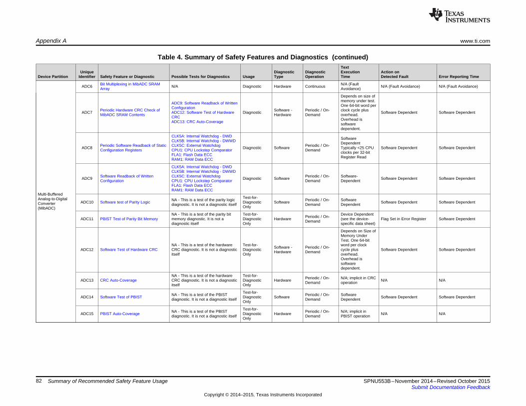
Appendix A www.ti.com
Table 4. Summary of Safety Features and Diagnostics (continued)Text
Unique Diagnostic Diagnostic Execution Action onDevice Partition Identifier Safety Feature or Diagnostic Possible Tests for Diagnostics Usage Type Operation Time Detected Fault Error Reporting Time
Bit Multiplexing in MibADC SRAM N/A (FaultADC6 N/A Diagnostic Hardware Continuous N/A (Fault Avoidance) N/A (Fault Avoidance)Array Avoidance)
Depends on size ofmemory under test.ADC9: Software Readback of Written One 64-bit word perConfigurationPeriodic Hardware CRC Check of Software - Periodic / On- clock cycle plusADC7 ADC12: Software Test of Hardware Diagnostic Software Dependent Software DependentMibADC SRAM Contents Hardware Demand overhead.CRC Overhead isADC13: CRC Auto-Coverage softwaredependent.
CLK5A: Internal Watchdog - DWD SoftwareCLK5B: Internal Watchdog - DWWD DependentPeriodic Software Readback of Static CLK5C: External Watchdog Periodic / On-ADC8 Diagnostic Software Typically <25 CPU Software Dependent Software DependentConfiguration Registers CPU1: CPU Lockstep Comparator Demand clocks per 32-bitFLA1: Flash Data ECC Register ReadRAM1: RAM Data ECC
CLK5A: Internal Watchdog - DWDCLK5B: Internal Watchdog - DWWD
Software Readback of Written CLK5C: External Watchdog Periodic / On- Software-ADC9 Diagnostic Software Software Dependent Software DependentConfiguration CPU1: CPU Lockstep Comparator Demand DependentFLA1: Flash Data ECCRAM1: RAM Data ECC
Multi-BufferedTest-for-Analog-to-Digital NA - This is a test of the parity logic Periodic / On- SoftwareADC10 Software test of Parity Logic Diagnostic Software Software Dependent Software DependentConverter diagnostic. It is not a diagnostic itself Demand DependentOnly(MibADC)
NA - This is a test of the parity bit Test-for- Device DependentPeriodic / On-ADC11 PBIST Test of Parity Bit Memory memory diagnostic. It is not a Diagnostic Hardware (see the device- Flag Set in Error Register Software DependentDemanddiagnostic itself Only specific data sheet)
Depends on Size ofMemory UnderTest. One 64-bit
NA - This is a test of the hardware Test-for- word per clockSoftware - Periodic / On-ADC12 Software Test of Hardware CRC CRC diagnostic. It is not a diagnostic Diagnostic cycle plus Software Dependent Software DependentHardware Demanditself Only overhead.Overhead issoftwaredependent.
NA - This is a test of the hardware Test-for- Periodic / On- N/A; implicit in CRCADC13 CRC Auto-Coverage CRC diagnostic. It is not a diagnostic Diagnostic Hardware N/A N/ADemand operationitself Only
Test-for-NA - This is a test of the PBIST Periodic / On- SoftwareADC14 Software Test of PBIST Diagnostic Software Software Dependent Software Dependentdiagnostic. It is not a diagnostic itself Demand DependentOnly
Test-for-NA - This is a test of the PBIST Periodic / On- N/A; implicit inADC15 PBIST Auto-Coverage Diagnostic Hardware N/A N/Adiagnostic. It is not a diagnostic itself Demand PBIST operationOnly
82 Summary of Recommended Safety Feature Usage SPNU553B–November 2014–Revised October 2015Submit Documentation Feedback
Copyright © 2014–2015, Texas Instruments Incorporated

www.ti.com Appendix A
Table 4. Summary of Safety Features and Diagnostics (continued)Text
Unique Diagnostic Diagnostic Execution Action onDevice Partition Identifier Safety Feature or Diagnostic Possible Tests for Diagnostics Usage Type Operation Time Detected Fault Error Reporting Time
Typically <1 µS to notifyHET11: Software Readback of CPU*Memory Protection Unit for HTU Bus Written Configuration No HardwareHET1 Diagnostic Hardware Continuous Interrupt Provided to CPU *(Interrupt handling time isMaster Accesses HET19: Software Test of MPU Overhead system load and softwareFunctionality dependent)
CLK5A: Internal Watchdog - DWDCLK5B: Internal Watchdog - DWWDCLK5C: External Watchdog Periodic / On- SoftwareHET2 Information Redundancy Techniques Diagnostic Software Software Dependent Software DependentCPU1: CPU Lockstep Comparator Demand DependentFLA1: Flash Data ECCRAM1: RAM Data ECC
HET11: Software Readback ofUse of DCC as Program Sequence Written Configuration Software - SoftwareHET3 Diagnostic Continuous Software Dependent Software DependentWatchdog HET20: Software Test of DCC Hardware Dependent
Operation
CLK5A: Internal Watchdog - DWD Software-CLK5B: Internal Watchdog - DWWD Dependent
Boot Time Software Test of Function CLK5C: External Watchdog Software - Periodic / On- HardwareHET5A Diagnostic Software Dependent Software DependentUsing I/O Loopback CPU1: CPU Lockstep Comparator Hardware Demand contribution to testFLA1: Flash Data ECC execution time isRAM1: RAM Data ECC negligible
CLK5A: Internal Watchdog - DWD Software-CLK5B: Internal Watchdog - DWWD Dependent
High-End Periodic Software Test of Function CLK5C: External Watchdog Software - Periodic / On- HardwareHET5B Diagnostic Software Dependent Software DependentTimer (N2HET) Using I/O Loopback CPU1: CPU Lockstep Comparator Hardware Demand contribution to testIncluding FLA1: Flash Data ECC execution time isHET Transfer Unit RAM1: RAM Data ECC negligible(HTU)
HET11: Software Readback of Typically <1 µS to notifyWritten Configuration CPU*No HardwareHET6 N2HET/HTU SRAM Data Parity HET13: Software test of Parity Logic Diagnostic Hardware Continuous Interrupt Provided to CPU *(Interrupt handling time isOverheadHET14: PBIST Test of Parity Bit system load and softwareMemory dependent)
HET11: Software Readback of Device DependentBoot Time PBIST Check of Written Configuration Periodic / On-HET7A Diagnostic Hardware (see the device- Flag Set in Error Register Software DependentN2HET/HTU SRAM HET17: Software Test of PBIST Demand specific data sheet)HET18: PBIST Auto-Coverage
HET11: Software Readback of Device DependentPeriodic PBIST Check of Written Configuration Periodic / On-HET7B Diagnostic Hardware (see the device- Flag Set in Error Register Software DependentN2HET/HTU SRAM HET17: Software Test of PBIST Demand specific data sheet)HET18: PBIST Auto-Coverage
Bit Multiplexing in N2HET/HTU N/A (FaultHET8 N/A - Fault Avoidance Diagnostic Hardware Continuous N/A (Fault Avoidance) N/A (Fault Avoidance)SRAM Array Avoidance)
Depends on size ofmemory under test.HET11: Software Readback of One 64-bit word perWritten ConfigurationPeriodic Hardware CRC Check of Software - Periodic / On- clock cycle plusHET9 HET15: Software Test of Hardware Diagnostic Software Dependent Software DependentN2HET/HTU SRAM Contents Hardware Demand overhead.CRC Overhead isHET16: CRC Auto-Coverage softwaredependent.
83SPNU553B–November 2014–Revised October 2015 Summary of Recommended Safety Feature UsageSubmit Documentation Feedback
Copyright © 2014–2015, Texas Instruments Incorporated

Appendix A www.ti.com
Table 4. Summary of Safety Features and Diagnostics (continued)Text
Unique Diagnostic Diagnostic Execution Action onDevice Partition Identifier Safety Feature or Diagnostic Possible Tests for Diagnostics Usage Type Operation Time Detected Fault Error Reporting Time
CLK5A: Internal Watchdog - DWD Software-CLK5B: Internal Watchdog - DWWD DependentPeriodic Software Readback of Static CLK5C: External Watchdog Periodic / On-HET10 Diagnostic Software Typically <25 CPU Software Dependent Software DependentConfiguration Registers CPU1: CPU Lockstep Comparator Demand clocks per 32-bitFLA1: Flash Data ECC Register ReadRAM1: RAM Data ECC
CLK5A: Internal Watchdog - DWDCLK5B: Internal Watchdog - DWWD
Software Readback of Written CLK5C: External Watchdog Periodic / On- SoftwareHET11 Diagnostic Software Software Dependent Software DependentConfiguration CPU1: CPU Lockstep Comparator Demand DependentFLA1: Flash Data ECCRAM1: RAM Data ECC
CLK5A: Internal Watchdog - DWDCLK5B: Internal Watchdog - DWWD
Transmission Redundancy (for CLK5C: External Watchdog Periodic / On-HET12 Diagnostic Software System Dependent System Dependent System DependentTransfer Unit) CPU1: CPU Lockstep Comparator DemandFLA1: Flash Data ECCRAM1: RAM Data ECC
Test-for-NA - This is a test of the parity logic Periodic / On- SoftwareHET13 Software test of Parity Logic Diagnostic Software Software Dependent Software Dependentdiagnostic. It is not a diagnostic itself Demand DependentOnly
NA - This is a test of the parity bit Test-for- Device DependentPeriodic / On-High-End HET14 PBIST Test of Parity Bit Memory memory diagnostic. It is not a Diagnostic Hardware (see the device- Flag Set in Error Register Software DependentDemandTimer (N2HET) diagnostic itself Only specific data sheet)IncludingHET Transfer Unit Depends on size of(HTU) memory under test.
One 64-bit word perNA - This is a test of the hardware Test-for- Software - Periodic / On- clock cycle plusHET15 Software Test of Hardware CRC CRC diagnostic. It is not a diagnostic Diagnostic Software Defined Software DependentHardware Demand overhead.itself Only Overhead issoftwaredependent.
NA - This is a test of the hardware Test-for- Periodic / On- N/A; implicit in CRCHET16 CRC Auto-Coverage CRC diagnostic. It is not a diagnostic Diagnostic Hardware N/A N/ADemand operationitself Only
Test-for-NA - This is a test of the PBIST Periodic / On- SoftwareHET17 Software Test of PBIST Diagnostic Software Software Dependent Software Dependentdiagnostic. It is not a diagnostic itself Demand DependentOnly
Test-for-NA - This is a test of the PBIST Periodic / On- N/A; implicit inHET18 PBIST Auto-Coverage Diagnostic Hardware N/A N/Adiagnostic. It is not a diagnostic itself Demand PBIST operationOnly
NA - This is a test of the MPU Test-for- Periodic / On- SoftwareHET19 Software Test of MPU Functionality functionality diagnostic. It is not a Diagnostic Software Software Dependent Software DependentDemand Dependentdiagnostic itself Only
NA - This is a test of the DCC Test-for- Periodic / On- SoftwareHET20 Software Test of DCC Functionality functionality diagnostic. It is not a Diagnostic Software Software Dependent Software DependentDemand Dependentdiagnostic itself Only
84 Summary of Recommended Safety Feature Usage SPNU553B–November 2014–Revised October 2015Submit Documentation Feedback
Copyright © 2014–2015, Texas Instruments Incorporated
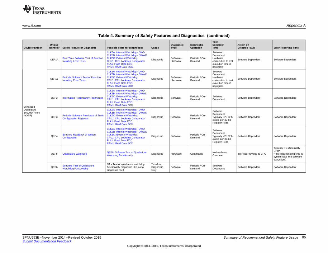
www.ti.com Appendix A
Table 4. Summary of Safety Features and Diagnostics (continued)Text
Unique Diagnostic Diagnostic Execution Action onDevice Partition Identifier Safety Feature or Diagnostic Possible Tests for Diagnostics Usage Type Operation Time Detected Fault Error Reporting Time
CLK5A: Internal Watchdog - DWD SoftwareCLK5B: Internal Watchdog - DWWD Dependent
Boot Time Software Test of Function CLK5C: External Watchdog Software - Periodic / On- HardwareQEP1A Diagnostic Software Dependent Software DependentIncluding Error Tests CPU1: CPU Lockstep Comparator Hardware Demand contribution to testFLA1: Flash Data ECC execution time isRAM1: RAM Data ECC negligible
CLK5A: Internal Watchdog - DWD SoftwareCLK5B: Internal Watchdog - DWWD Dependent
Periodic Software Test of Function CLK5C: External Watchdog Software - Periodic / On- HardwareQEP1B Diagnostic Software Dependent Software DependentIncluding Error Tests CPU1: CPU Lockstep Comparator Hardware Demand contribution to testFLA1: Flash Data ECC execution time isRAM1: RAM Data ECC negligible
CLK5A: Internal Watchdog - DWDCLK5B: Internal Watchdog - DWWDCLK5C: External Watchdog Periodic / On- SoftwareQEP2 Information Redundancy Techniques Diagnostic Software Software Dependent Software DependentCPU1: CPU Lockstep Comparator Demand DependentFLA1: Flash Data ECCRAM1: RAM Data ECC
EnhancedQuadrature CLK5A: Internal Watchdog - DWD SoftwareEncoder Pulse CLK5B: Internal Watchdog - DWWD Dependent(eQEP) Periodic Software Readback of Static CLK5C: External Watchdog Periodic / On-QEP3 Diagnostic Software Typically <25 CPU Software Dependent Software DependentConfiguration Registers CPU1: CPU Lockstep Comparator Demand clocks per 32-bitFLA1: Flash Data ECC Register ReadRAM1: RAM Data ECC
CLK5A: Internal Watchdog - DWD SoftwareCLK5B: Internal Watchdog - DWWD DependentSoftware Readback of Written CLK5C: External Watchdog Periodic / On-QEP4 Diagnostic Software Typically <25 CPU Software Dependent Software DependentConfiguration CPU1: CPU Lockstep Comparator Demand clocks per 32-bitFLA1: Flash Data ECC Register ReadRAM1: RAM Data ECC
Typically <1 µS to notifyCPU*QEP6: Software Test of Quadrature No HardwareQEP5 Quadrature Watchdog Diagnostic Hardware Continuous Interrupt Provided to CPU *(Interrupt handling time isWatchdog Functionality Overhead system load and softwaredependent)
NA - Test of quadrature watchdog Test-for-Software Test of Quadrature Periodic / On- SoftwareQEP6 functionality diagnostic. It is not a Diagnostic Software Software Dependent Software DependentWatchdog Functionality Demand Dependentdiagnostic itself Only
85SPNU553B–November 2014–Revised October 2015 Summary of Recommended Safety Feature UsageSubmit Documentation Feedback
Copyright © 2014–2015, Texas Instruments Incorporated

Appendix A www.ti.com
Table 4. Summary of Safety Features and Diagnostics (continued)Text
Unique Diagnostic Diagnostic Execution Action onDevice Partition Identifier Safety Feature or Diagnostic Possible Tests for Diagnostics Usage Type Operation Time Detected Fault Error Reporting Time
CLK5A: Internal Watchdog - DWD Software-CLK5B: Internal Watchdog - DWWD Dependent
Boot Time Software Test of Function CLK5C: External Watchdog Software - Periodic / On- HardwareMSP1A Diagnostic Software Dependent Software DependentUsing I/O Loopback CPU1: CPU Lockstep Comparator Hardware Demand contribution to testFLA1: Flash Data ECC execution time isRAM1: RAM Data ECC negligible
CLK5A: Internal Watchdog - DWD Software-CLK5B: Internal Watchdog - DWWD Dependent
Periodic Software Test of Function CLK5C: External Watchdog Software / Periodic / On- HardwareMSP1B Diagnostic Software Defined Software-DependentUsing I/O Loopback CPU1: CPU Lockstep Comparator Hardware Demand contribution to testFLA1: Flash Data ECC execution time isRAM1: RAM Data ECC negligible
Typically <1 µS to notifyCPU*MSP9: Software Readback of Written No HardwareMSP2 Parity in Message Diagnostic Hardware Continuous Interrupt Provided to CPU *(Interrupt handling time isConfiguration Overhead system load and softwaredependent)
CLK5A: Internal Watchdog - DWDCLK5B: Internal Watchdog - DWWDCLK5C: External Watchdog Periodic / On- SoftwareMSP3 Information Redundancy Techniques Diagnostic Software Software Dependent Software DependentCPU1: CPU Lockstep Comparator Demand DependentFLA1: Flash Data ECCMulti-BufferedRAM1: RAM Data ECCSerial
Peripheral Interface MSP9: Software Readback of Written Typically <1 µS to notify(MibSPI) Configuration CPU*No HardwareMSP4 MibSPI SRAM Data Parity MSP16: Software test of Parity Logic Diagnostic Hardware Continuous Interrupt Provided to CPU *(Interrupt handling time isOverheadMSP17: PBIST Test of Parity Bit system load and software
Memory dependent)
MSP9: Software Readback of WrittenConfigurationMSP20: Software Test of PBIST Device DependentBoot Time PBIST Check of MibSPI MSP21: PBIST Auto-Coverage Periodic / On-MSP5A Diagnostic Hardware (see the device- Flag Set in Error Register Software DependentSRAM CLK5C: External Watchdog Demand specific data sheet)CPU1: CPU Lockstep ComparatorFLA1: Flash Data ECCRAM1: RAM Data ECC
MSP9: Software Readback of WrittenConfigurationMSP20: Software Test of PBIST Device DependentPeriodic PBIST Check of MibSPI MSP21: PBIST Auto-Coverage Periodic / On-MSP5B Diagnostic Hardware (see the device- Flag Set in Error Register Software DependentSRAM CLK5C: External Watchdog Demand specific data sheet)CPU1: CPU Lockstep ComparatorFLA1: Flash Data ECCRAM1: RAM Data ECC
Bit Multiplexing in MibSPI SRAM N/A (FaultMSP6 N/A Diagnostic Hardware Continuous N/A (Fault Avoidance) N/A (Fault Avoidance)Array Avoidance)
86 Summary of Recommended Safety Feature Usage SPNU553B–November 2014–Revised October 2015Submit Documentation Feedback
Copyright © 2014–2015, Texas Instruments Incorporated

www.ti.com Appendix A
Table 4. Summary of Safety Features and Diagnostics (continued)Text
Unique Diagnostic Diagnostic Execution Action onDevice Partition Identifier Safety Feature or Diagnostic Possible Tests for Diagnostics Usage Type Operation Time Detected Fault Error Reporting Time
Depends on size ofmemory under test.MSP9: Software Readback of Written One 64-bit word perConfigurationPeriodic Hardware CRC Check of Software - Periodic / On- clock cycle plusMSP7 MSP18: Software Test of Hardware Diagnostic Software Dependent Software DependentMibSPI SRAM Contents Hardware Demand overhead.CRC Overhead isMSP19: CRC Auto-Coverage softwaredependent.
CLK5A: Internal Watchdog - DWD SoftwareCLK5B: Internal Watchdog - DWWD DependentPeriodic Software Readback of Static CLK5C: External Watchdog Periodic / On-MSP8 Diagnostic Software Typically <25 CPU Software Dependent Software DependentConfiguration Registers CPU1: CPU Lockstep Comparator Demand clocks per 32-bitFLA1: Flash Data ECC Register ReadRAM1: RAM Data ECC
CLK5A: Internal Watchdog - DWDCLK5B: Internal Watchdog - DWWD
Software Readback of Written CLK5C: External Watchdog Periodic / On- SoftwareMSP9 Diagnostic Software Software Dependent Software DependentConfiguration CPU1: CPU Lockstep Comparator Demand DependentFLA1: Flash Data ECCRAM1: RAM Data ECC
CLK5A: Internal Watchdog - DWDCLK5B: Internal Watchdog - DWWDCLK5C: External Watchdog Periodic / On-MSP10 Transmission Redundancy Diagnostic Software System Dependent System Defined System DependentCPU1: CPU Lockstep Comparator DemandFLA1: Flash Data ECCRAM1: RAM Data ECC
Multi-BufferedTypically <1 µS to notifySerialCPU*Peripheral Interface MSP9: Software Readback of Written No HardwareMSP11 Data Overrun Error Detection Diagnostic Hardware Continuous Interrupt Provided to CPU *(Interrupt handling time is(MibSPI) Configuration Overhead system load and softwaredependent)
Typically <1 µS to notifyCPU*MSP9: Software Readback of Written No HardwareMSP12 Bit Error Detection Diagnostic Hardware Continuous Interrupt Provided to CPU *(Interrupt handling time isConfiguration Overhead system load and softwaredependent)
Typically <1 µS to notifyCPU*MSP9: Software Readback of Written No HardwareMSP13 Slave Desync Detection Diagnostic Hardware Continuous Interrupt Provided to CPU *(Interrupt handling time isConfiguration Overhead system load and softwaredependent)
Typically <1 µS to notifyCPU*MSP9: Software Readback of Written No HardwareMSP14 Slave Timeout Detection Diagnostic Hardware Continuous Interrupt Provided to CPU *(Interrupt handling time isConfiguration Overhead system load and softwaredependent)
Typically <1 µS to notifyCPU*MSP9: Software Readback of Written No HardwareMSP15 Data Length Error Detection Diagnostic Hardware Continuous Interrupt Provided to CPU *(Interrupt handling time isConfiguration Overhead system load and softwaredependent)
Test-for-NA - This is a test of the parity logic. Periodic / On- SoftwareMSP16 Software test of Parity Logic Diagnostic Software Software Dependent Software DependentIt is not a diagnostic itself Demand DependentOnly
87SPNU553B–November 2014–Revised October 2015 Summary of Recommended Safety Feature UsageSubmit Documentation Feedback
Copyright © 2014–2015, Texas Instruments Incorporated

Appendix A www.ti.com
Table 4. Summary of Safety Features and Diagnostics (continued)Text
Unique Diagnostic Diagnostic Execution Action onDevice Partition Identifier Safety Feature or Diagnostic Possible Tests for Diagnostics Usage Type Operation Time Detected Fault Error Reporting Time
Test-for- Device DependentNA - This is a test of the parity bit Periodic / On-MSP17 PBIST Test of Parity Bit Memory Diagnostic Hardware (see the device- Flag Set in Error Register Software Dependentmemory. It is not a diagnostic itself DemandOnly specific data sheet)
Depends on size ofmemory under test.One 64-bit word perNA - This is a test of the hardware Test-for- Software - Periodic / On- clock cycle plusMSP18 Software Test of Hardware CRC CRC diagnostic. It is not a diagnostic Diagnostic Software Dependent Software DependentHardware Demand overhead.itself Only Overhead is
Multi-Buffered softwareSerial dependent.Peripheral Interface(MibSPI) NA - This is a test of the hardware Test-for- Periodic / On- N/A; implicit in CRCMSP19 CRC Auto-Coverage CRC diagnostic. It is not a diagnostic Diagnostic Hardware N/A N/ADemand operationitself Only
Test-for-NA - This is a test of the PBIST Periodic / On- SoftwareMSP20 Software Test of PBIST Diagnostic Software Software Dependent Software Dependentdiagnostic. It is not a diagnostic itself Demand DependentOnly
Test-for-NA - This is a test of the PBIST Periodic / On- N/A; implicit inMSP21 PBIST Auto-Coverage Diagnostic Hardware N/A N/Adiagnostic. It is not a diagnostic itself Demand PBIST operationOnly
88 Summary of Recommended Safety Feature Usage SPNU553B–November 2014–Revised October 2015Submit Documentation Feedback
Copyright © 2014–2015, Texas Instruments Incorporated
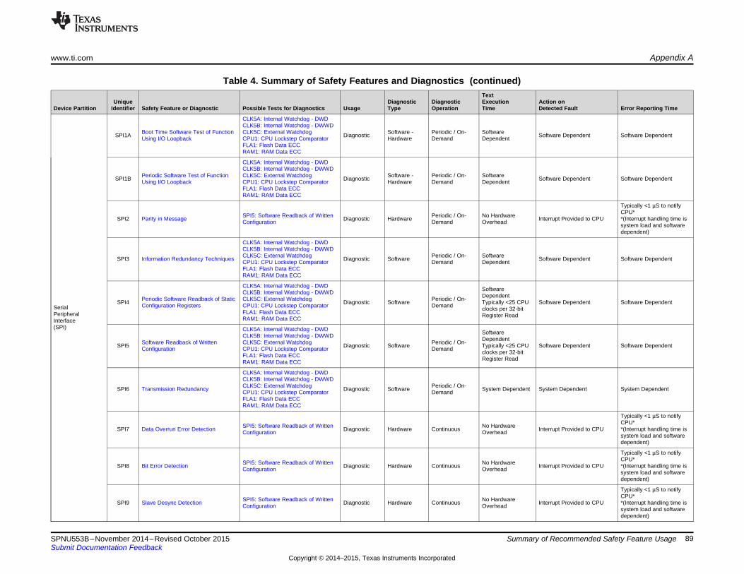
www.ti.com Appendix A
Table 4. Summary of Safety Features and Diagnostics (continued)Text
Unique Diagnostic Diagnostic Execution Action onDevice Partition Identifier Safety Feature or Diagnostic Possible Tests for Diagnostics Usage Type Operation Time Detected Fault Error Reporting Time
CLK5A: Internal Watchdog - DWDCLK5B: Internal Watchdog - DWWD
Boot Time Software Test of Function CLK5C: External Watchdog Software - Periodic / On- SoftwareSPI1A Diagnostic Software Dependent Software DependentUsing I/O Loopback CPU1: CPU Lockstep Comparator Hardware Demand DependentFLA1: Flash Data ECCRAM1: RAM Data ECC
CLK5A: Internal Watchdog - DWDCLK5B: Internal Watchdog - DWWD
Periodic Software Test of Function CLK5C: External Watchdog Software - Periodic / On- SoftwareSPI1B Diagnostic Software Dependent Software DependentUsing I/O Loopback CPU1: CPU Lockstep Comparator Hardware Demand DependentFLA1: Flash Data ECCRAM1: RAM Data ECC
Typically <1 µS to notifyCPU*SPI5: Software Readback of Written Periodic / On- No HardwareSPI2 Parity in Message Diagnostic Hardware Interrupt Provided to CPU *(Interrupt handling time isConfiguration Demand Overhead system load and softwaredependent)
CLK5A: Internal Watchdog - DWDCLK5B: Internal Watchdog - DWWDCLK5C: External Watchdog Periodic / On- SoftwareSPI3 Information Redundancy Techniques Diagnostic Software Software Dependent Software DependentCPU1: CPU Lockstep Comparator Demand DependentFLA1: Flash Data ECCRAM1: RAM Data ECC
CLK5A: Internal Watchdog - DWD SoftwareCLK5B: Internal Watchdog - DWWD DependentPeriodic Software Readback of Static CLK5C: External Watchdog Periodic / On-SPI4 Diagnostic Software Typically <25 CPU Software Dependent Software DependentConfiguration Registers CPU1: CPU Lockstep Comparator DemandSerial clocks per 32-bitFLA1: Flash Data ECCPeripheral Register ReadRAM1: RAM Data ECCInterface(SPI) CLK5A: Internal Watchdog - DWD SoftwareCLK5B: Internal Watchdog - DWWD DependentSoftware Readback of Written CLK5C: External Watchdog Periodic / On-SPI5 Diagnostic Software Typically <25 CPU Software Dependent Software DependentConfiguration CPU1: CPU Lockstep Comparator Demand clocks per 32-bitFLA1: Flash Data ECC Register ReadRAM1: RAM Data ECC
CLK5A: Internal Watchdog - DWDCLK5B: Internal Watchdog - DWWDCLK5C: External Watchdog Periodic / On-SPI6 Transmission Redundancy Diagnostic Software System Dependent System Dependent System DependentCPU1: CPU Lockstep Comparator DemandFLA1: Flash Data ECCRAM1: RAM Data ECC
Typically <1 µS to notifyCPU*SPI5: Software Readback of Written No HardwareSPI7 Data Overrun Error Detection Diagnostic Hardware Continuous Interrupt Provided to CPU *(Interrupt handling time isConfiguration Overhead system load and softwaredependent)
Typically <1 µS to notifyCPU*SPI5: Software Readback of Written No HardwareSPI8 Bit Error Detection Diagnostic Hardware Continuous Interrupt Provided to CPU *(Interrupt handling time isConfiguration Overhead system load and softwaredependent)
Typically <1 µS to notifyCPU*SPI5: Software Readback of Written No HardwareSPI9 Slave Desync Detection Diagnostic Hardware Continuous Interrupt Provided to CPU *(Interrupt handling time isConfiguration Overhead system load and softwaredependent)
89SPNU553B–November 2014–Revised October 2015 Summary of Recommended Safety Feature UsageSubmit Documentation Feedback
Copyright © 2014–2015, Texas Instruments Incorporated

Appendix A www.ti.com
Table 4. Summary of Safety Features and Diagnostics (continued)Text
Unique Diagnostic Diagnostic Execution Action onDevice Partition Identifier Safety Feature or Diagnostic Possible Tests for Diagnostics Usage Type Operation Time Detected Fault Error Reporting Time
Typically <1 µS to notifyCPU*SPI5: Software Readback of Written No HardwareSPI10 Slave Timeout Detection Diagnostic Hardware Continuous Interrupt Provided to CPU *(Interrupt handling time isConfiguration Overhead system load and softwareSerialdependent)Peripheral
Interface Typically <1 µS to notify(SPI) CPU*SPI5: Software Readback of Written No HardwareSPI11 Data Length Error Detection Diagnostic Hardware Continuous Interrupt Provided to CPU *(Interrupt handling time isConfiguration Overhead system load and software
dependent)
90 Summary of Recommended Safety Feature Usage SPNU553B–November 2014–Revised October 2015Submit Documentation Feedback
Copyright © 2014–2015, Texas Instruments Incorporated

www.ti.com Appendix A
Table 4. Summary of Safety Features and Diagnostics (continued)Text
Unique Diagnostic Diagnostic Execution Action onDevice Partition Identifier Safety Feature or Diagnostic Possible Tests for Diagnostics Usage Type Operation Time Detected Fault Error Reporting Time
CLK5A: Internal Watchdog - DWDCLK5B: Internal Watchdog - DWWD
Boot Time Software Test of Function CLK5C: External Watchdog Software - Software-LIN1A Diagnostic On Demand Software Defined Software-DependentUsing I/O Loopback CPU1: CPU Lockstep Comparator Hardware DependentFLA1: Flash Data ECCRAM1: RAM Data ECC
CLK5A: Internal Watchdog - DWDCLK5B: Internal Watchdog - DWWD
Periodic Software Test of Function CLK5C: External Watchdog Software - Software-LIN1B Diagnostic On Demand Software Defined Software-DependentUsing I/O Loopback CPU1: CPU Lockstep Comparator Hardware DependentFLA1: Flash Data ECCRAM1: RAM Data ECC
CLK5A: Internal Watchdog - DWDCLK5B: Internal Watchdog - DWWDCLK5C: External Watchdog Software-LIN2 Information Redundancy Techniques Diagnostic Software On Demand Software Defined Software-DependentCPU1: CPU Lockstep Comparator DependentFLA1: Flash Data ECCRAM1: RAM Data ECC
CLK5A: Internal Watchdog - DWD Software-CLK5B: Internal Watchdog - DWWD Dependent.Periodic Software Readback of Static CLK5C: External WatchdogLIN3 Diagnostic Software On Demand Typically <25 CPU Software Defined Software-DependentConfiguration Registers CPU1: CPU Lockstep Comparator clocks per 32-bitFLA1: Flash Data ECC Register ReadRAM1: RAM Data ECC
CLK5A: Internal Watchdog - DWDCLK5B: Internal Watchdog - DWWD
Software Readback of Written CLK5C: External Watchdog SoftwareLIN4 Diagnostic Software On Demand Software Defined Software-DependentConfiguration CPU1: CPU Lockstep Comparator DependentLocal InterconnectFLA1: Flash Data ECCNetwork (LIN)RAM1: RAM Data ECC
CLK5A: Internal Watchdog - DWDCLK5B: Internal Watchdog - DWWDCLK5C: External WatchdogLIN5 Transmission Redundancy Diagnostic Software On Demand System Dependent System Defined System DependentCPU1: CPU Lockstep ComparatorFLA1: Flash Data ECCRAM1: RAM Data ECC
Typically <1 µS to notifyCPU*LIN4: Software Readback of Written No OverheadLIN6 Overrun Error Detection Diagnostic Hardware Continuous Interrupt Provided to CPU *(Interrupt handling time isConfiguration (Same clock cycle) system load and softwaredependent)
Typically <1 µS to notifyCPU*LIN4: Software Readback of Written No OverheadLIN7 Frame Error Detection Diagnostic Hardware Continuous Interrupt Provided to CPU *(Interrupt handling time isConfiguration (Same clock cycle) system load and softwaredependent)
Typically <1 µS to notifyCPU*LIN4: Software Readback of Written No OverheadLIN8 Physical Bus Error Detection Diagnostic Hardware Continuous Interrupt Provided to CPU *(Interrupt handling time isConfiguration (Same clock cycle) system load and softwaredependent)
Typically <1 µS to notifyCPU*LIN4: Software Readback of Written No OverheadLIN9 No-Response Error Detection Diagnostic Hardware Continuous Interrupt Provided to CPU *(Interrupt handling time isConfiguration (Same clock cycle) system load and softwaredependent)
91SPNU553B–November 2014–Revised October 2015 Summary of Recommended Safety Feature UsageSubmit Documentation Feedback
Copyright © 2014–2015, Texas Instruments Incorporated
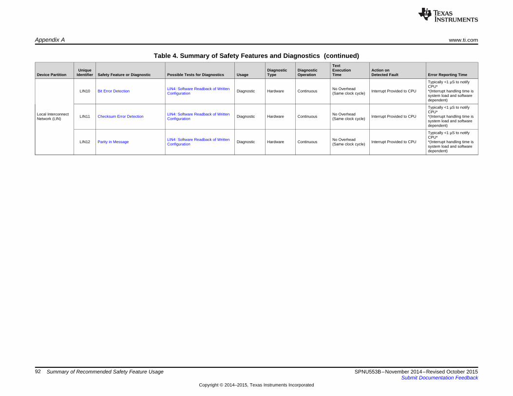
Appendix A www.ti.com
Table 4. Summary of Safety Features and Diagnostics (continued)Text
Unique Diagnostic Diagnostic Execution Action onDevice Partition Identifier Safety Feature or Diagnostic Possible Tests for Diagnostics Usage Type Operation Time Detected Fault Error Reporting Time
Typically <1 µS to notifyCPU*LIN4: Software Readback of Written No OverheadLIN10 Bit Error Detection Diagnostic Hardware Continuous Interrupt Provided to CPU *(Interrupt handling time isConfiguration (Same clock cycle) system load and softwaredependent)
Typically <1 µS to notifyCPU*Local Interconnect LIN4: Software Readback of Written No OverheadLIN11 Checksum Error Detection Diagnostic Hardware Continuous Interrupt Provided to CPU *(Interrupt handling time isNetwork (LIN) Configuration (Same clock cycle) system load and softwaredependent)
Typically <1 µS to notifyCPU*LIN4: Software Readback of Written No OverheadLIN12 Parity in Message Diagnostic Hardware Continuous Interrupt Provided to CPU *(Interrupt handling time isConfiguration (Same clock cycle) system load and softwaredependent)
92 Summary of Recommended Safety Feature Usage SPNU553B–November 2014–Revised October 2015Submit Documentation Feedback
Copyright © 2014–2015, Texas Instruments Incorporated

www.ti.com Appendix A
Table 4. Summary of Safety Features and Diagnostics (continued)Text
Unique Diagnostic Diagnostic Execution Action onDevice Partition Identifier Safety Feature or Diagnostic Possible Tests for Diagnostics Usage Type Operation Time Detected Fault Error Reporting Time
CLK5A: Internal Watchdog - DWDCLK5B: Internal Watchdog - DWWD
Boot Time Software Test of Function CLK5C: External Watchdog Software- SoftwareCAN1A Diagnostic On Demand Software Dependent Software DependentUsing I/O Loopback CPU1: CPU Lockstep Comparator Hardware DependentFLA1: Flash Data ECCRAM1: RAM Data ECC
CLK5A: Internal Watchdog - DWDCLK5B: Internal Watchdog - DWWD
Periodic Software Test of Function CLK5C: External Watchdog Software- SoftwareCAN1B Diagnostic On Demand Software Dependent Software DependentUsing I/O Loopback CPU1: CPU Lockstep Comparator Hardware DependentFLA1: Flash Data ECCRAM1: RAM Data ECC
CLK5A: Internal Watchdog - DWDCLK5B: Internal Watchdog - DWWDCLK5C: External Watchdog SoftwareCAN2 Information Redundancy Techniques Diagnostic Software On Demand Software Dependent Software DependentCPU1: CPU Lockstep Comparator DependentFLA1: Flash Data ECCRAM1: RAM Data ECC
CAN8: Software Readback of Written Typically <1 µS to notifyConfiguration CPU*No HardwareCAN3 DCAN SRAM Data Parity CAN15: Software test of Parity Logic Diagnostic Hardware Continuous Interrupt Provided to CPU *(Interrupt handling time isOverheadCAN16: PBIST Test of Parity Bit system load and softwareMemory dependent)
CAN8: Software Readback of WrittenConfigurationCAN19: Software Test of PBIST Device DependentBoot Time PBIST Check of DCAN CAN20: PBIST Auto-CoverageController Area CAN4A Diagnostic Hardware On Demand (see the device- Flag Set in Error Register Software DependentSRAM CLK5C: External WatchdogNetwork (DCAN) specific data sheet)CPU1: CPU Lockstep ComparatorFLA1: Flash Data ECCRAM1: RAM Data ECC
CAN8: Software Readback of WrittenConfigurationCAN19: Software Test of PBIST Device DependentPeriodic PBIST Check of DCAN CAN20: PBIST Auto-CoverageCAN4B Diagnostic Hardware On Demand (see the device- Flag Set in Error Register Software DependentSRAM CLK5C: External Watchdog specific data sheet)CPU1: CPU Lockstep ComparatorFLA1: Flash Data ECCRAM1: RAM Data ECC
N/A - FaultCAN5 Bit Multiplexing in DCAN SRAM Array N/A - Fault Avoidance Diagnostic Hardware Continuous N/A - Fault Avoidance N/A - Fault AvoidanceAvoidance
Depends on size ofmemory under test.CAN8: Software Readback of Written One 64-bit word perConfigurationPeriodic Hardware CRC Check of Software- clock cycle plusCAN6 CAN17: Software Test of Hardware Diagnostic On Demand Software Dependent Software DependentDCAN SRAM Contents Hardware overhead.CRC Overhead isCAN18: CRC Auto-Coverage softwaredependent.
CLK5A: Internal Watchdog - DWD SoftwareCLK5B: Internal Watchdog - DWWD DependentPeriodic Software Readback of Static CLK5C: External Watchdog Periodic / On-CAN7 Diagnostic Software Typically <25 CPU Software Dependent Software DependentConfiguration Registers CPU1: CPU Lockstep Comparator Demand clocks per 32-bitFLA1: Flash Data ECC Register ReadRAM1: RAM Data ECC
93SPNU553B–November 2014–Revised October 2015 Summary of Recommended Safety Feature UsageSubmit Documentation Feedback
Copyright © 2014–2015, Texas Instruments Incorporated
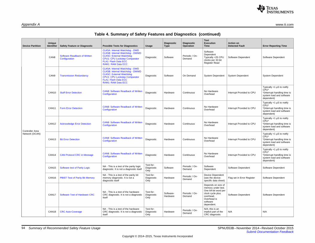
Appendix A www.ti.com
Table 4. Summary of Safety Features and Diagnostics (continued)Text
Unique Diagnostic Diagnostic Execution Action onDevice Partition Identifier Safety Feature or Diagnostic Possible Tests for Diagnostics Usage Type Operation Time Detected Fault Error Reporting Time
CLK5A: Internal Watchdog - DWD SoftwareCLK5B: Internal Watchdog - DWWD DependentSoftware Readback of Written CLK5C: External Watchdog Periodic / On-CAN8 Diagnostic Software Typically <25 CPU Software Dependent Software DependentConfiguration CPU1: CPU Lockstep Comparator Demand clocks per 32-bitFLA1: Flash Data ECC Register ReadRAM1: RAM Data ECC
CLK5A: Internal Watchdog - DWDCLK5B: Internal Watchdog - DWWDCLK5C: External WatchdogCAN9 Transmission Redundancy Diagnostic Software On Demand System Dependent System Dependent System DependentCPU1: CPU Lockstep ComparatorFLA1: Flash Data ECCRAM1: RAM Data ECC
Typically <1 µS to notifyCPU*CAN8: Software Readback of Written No HardwareCAN10 Stuff Error Detection Diagnostic Hardware Continuous Interrupt Provided to CPU *(Interrupt handling time isConfiguration Overhead system load and softwaredependent)
Typically <1 µS to notifyCPU*CAN8: Software Readback of Written No HardwareCAN11 Form Error Detection Diagnostic Hardware Continuous Interrupt Provided to CPU *(Interrupt handling time isConfiguration Overhead system load and softwaredependent)
Typically <1 µS to notifyCPU*CAN8: Software Readback of Written No HardwareCAN12 Acknowledge Error Detection Diagnostic Hardware Continuous Interrupt Provided to CPU *(Interrupt handling time isConfiguration Overhead system load and softwaredependent)
Controller AreaNetwork (DCAN) Typically <1 µS to notify
CPU*CAN8: Software Readback of Written No HardwareCAN13 Bit Error Detection Diagnostic Hardware Continuous Interrupt Provided to CPU *(Interrupt handling time isConfiguration Overhead system load and softwaredependent)
Typically <1 µS to notifyCPU*CAN8: Software Readback of Written No HardwareCAN14 CAN Protocol CRC in Message Diagnostic Hardware Continuous Interrupt Provided to CPU *(Interrupt handling time isConfiguration Overhead system load and softwaredependent)
Test-for-NA - This is a test of the parity logic Periodic / On- SoftwareCAN15 Software test of Parity Logic Diagnostic Software Software Dependent Software Dependentdiagnostic. It is not a diagnostic itself Demand DependentOnly
NA - This is a test of the parity bit Test-for- Device DependentPeriodic / On-CAN16 PBIST Test of Parity Bit Memory memory diagnostic. It is not a Diagnostic Hardware (see the device- Flag set in Error Register Software DependentDemanddiagnostic itself Only specific data sheet)
Depends on size ofmemory under test.One 64-bit word perNA - This is a test of the hardware Test-for- Software- Periodic / On- clock cycle plusCAN17 Software Test of Hardware CRC CRC diagnostic. It is not a diagnostic Diagnostic Software Dependent Software DependentHardware Demand overhead.itself Only Overhead issoftwaredependent.
NA - This is a test of the hardware Test-for- N/A; this is anPeriodic / On-CAN18 CRC Auto-Coverage CRC diagnostic. It is not a diagnostic Diagnostic Hardware implicit part of the N/A N/ADemanditself Only CRC diagnostic
94 Summary of Recommended Safety Feature Usage SPNU553B–November 2014–Revised October 2015Submit Documentation Feedback
Copyright © 2014–2015, Texas Instruments Incorporated

www.ti.com Appendix A
Table 4. Summary of Safety Features and Diagnostics (continued)Text
Unique Diagnostic Diagnostic Execution Action onDevice Partition Identifier Safety Feature or Diagnostic Possible Tests for Diagnostics Usage Type Operation Time Detected Fault Error Reporting Time
Test-for-NA - This is a test of the PBIST Periodic / On- SoftwareCAN19 Software Test of PBIST Diagnostic Software Software Dependent Software Dependentdiagnostic. It is not a diagnostic itself Demand DependentOnlyController AreaNetwork (DCAN) Test-for- N/A; this is anNA - This is a test of the PBIST Periodic / On-CAN20 PBIST Auto-Coverage Diagnostic Hardware implicit part of the N/A N/Adiagnostic. It is not a diagnostic itself DemandOnly PBIST diagnostic
CLK5A: Internal Watchdog - DWD SoftwareCLK5B: Internal Watchdog - DWWD Dependent
Boot Time Software Test of Function CLK5C: External Watchdog Software - Periodic / On- HardwareGIO1A Diagnostic Software Dependent Software DependentUsing I/O Checking In GIO Mode CPU1: CPU Lockstep Comparator Hardware Demand contribution to testFLA1: Flash Data ECC execution time isRAM1: RAM Data ECC negligible
CLK5A: Internal Watchdog - DWD SoftwareCLK5B: Internal Watchdog - DWWD Dependent
Periodic Software Test of Function CLK5C: External Watchdog Software - Periodic / On- HardwareGIO1B Diagnostic Software Dependent Software DependentUsing I/O Checking In GIO Mode CPU1: CPU Lockstep Comparator Hardware Demand contribution to testFLA1: Flash Data ECC execution time isRAM1: RAM Data ECC negligible
CLK5A: Internal Watchdog - DWDCLK5B: Internal Watchdog - DWWD
General Purpose CLK5C: External Watchdog Periodic / On- SoftwareGIO2 Information Redundancy Techniques Diagnostic Software Software Dependent Software DependentInput/Output (GIO) CPU1: CPU Lockstep Comparator Demand DependentFLA1: Flash Data ECCRAM1: RAM Data ECC
CLK5A: Internal Watchdog - DWD SoftwareCLK5B: Internal Watchdog - DWWD DependentPeriodic Software Readback of Static CLK5C: External Watchdog Periodic / On-GIO3 Diagnostic Software Typically <25 CPU Software Dependent Software DependentConfiguration Registers CPU1: CPU Lockstep Comparator Demand clocks per 32-bitFLA1: Flash Data ECC Register ReadRAM1: RAM Data ECC
CLK5A: Internal Watchdog - DWD SoftwareCLK5B: Internal Watchdog - DWWD DependentSoftware Readback of Written CLK5C: External Watchdog Periodic / On-GIO4 Diagnostic Software Typically <25 CPU Software Dependent Software DependentConfiguration CPU1: CPU Lockstep Comparator Demand clocks per 32-bitFLA1: Flash Data ECC Register ReadRAM1: RAM Data ECC
No HardwareJoint Technical JTG1 Hardware Disable of JTAG Port N/A Diagnostic Hardware Continuous N/A (Fault Avoidance) N/A (Fault Avoidance)OverheadActionGroup (JTAG) No HardwareJTG2 Lockout of JTAG Access Using AJSM N/A Diagnostic Hardware Continuous JTAG Access Blocked N/A (Fault Avoidance)Debug Overhead
Use of MPUs to Block Access to No Hardware Same CPU cycle as faultCortex-R4 Central DBG1 N/A Diagnostic Hardware Continuous Data abortMemory-Mapped Debug Overhead detectedProcessing Unit(CPU) Use of CoreSight Debug Logic Key No HardwareDBG2 N/A Diagnostic Hardware Continuous Debug Access Locked N/A (Fault Avoidance)Debug Enable Scheme Overhead
95SPNU553B–November 2014–Revised October 2015 Summary of Recommended Safety Feature UsageSubmit Documentation Feedback
Copyright © 2014–2015, Texas Instruments Incorporated

Appendix BSPNU553B–November 2014–Revised October 2015
Development Interface Agreement
A Development Interface Agreement (DIA) is intended to capture an agreement between a customer andsupplier towards the management of shared responsibilities in developing a functional safety system. Incustom developments, the DIA is a key document executed between customer and supplier early in thedevelopment process. As the Hercules family is a commercial, off the shelf (COTS) product, TI hasprepared a standard DIA within this section that describes the support that TI can provide for customerdevelopments. Requests for custom DIAs should be referred to your local TI sales office for disposition.
B.1 Appointment of Safety ManagersTexas Instruments has developed the Hercules MCUs with one or more development specialist safetymanagers in place throughout the silicon design, release to market, and release to production. Safetymanagement after release to production is maintained by separate safety managers who specialize inproduction and operation issues. Safety management responsibilities are continued through product end-of-life.
B.2 Tailoring of the Safety LifecycleTI has tailored the safety lifecycles of IEC 61508 to best match the needs of a safety element out ofcontext (SEooC). The tailoring activity has been executed in conjunction with input from exida andYogitech to ensure application of state of the art techniques and measures.
Key elements of the tailored safety lifecycle are:• Assumptions on system level design, safety concept, and requirements• Combined qualitative and quantitative or similar safety analysis techniques comprehending the sum of
silicon failure modes and diagnostic techniques known to both TI and Yogitech• Fault estimation based on multiple industry standards as well as TI "real-world" reliability data• Application of Yogitech's state-of-the-art fault injection methodology for validation of claimed diagnostic
coverage• Integration of lessons learned by through multiple safety critical developments to IEC 61508
96 Development Interface Agreement SPNU553B–November 2014–Revised October 2015Submit Documentation Feedback
Copyright © 2014–2015, Texas Instruments Incorporated
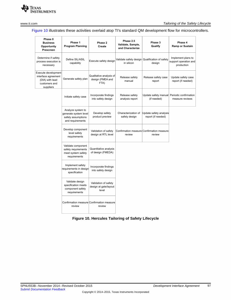
Phase 0
Business
Opportunity
Prescreen
Phase 1
Program Planning
Phase 2
Create
Phase 2.5
Validate, Sample,
and Characterize
Phase 3
Qualify
Phase 4
Ramp or Sustain
Determine if safety
process execution is
necessary
Execute development
interface agreement
(DIA) with lead
customers and
suppliers
Define SIL/ASIL
capability
Generate safety plan
Initiate safety case
Analyze system to
generate system level
safety assumptions
and requirements
Develop component
level safety
requirements
Validate component
safety requirements
meet system safety
requirements
Implement safety
requirements in design
specification
Validate design
specification meets
component safety
requirements
Confirmation measure
review
Validate safety design
in silicon
Release safety
manual
Release safety
analysis report
Characterization of
safety design
Confirmation measure
review
Qualification of safety
design
Release safety case
report
Update safety manual
(if needed)
Update safety analysis
report (if needed)
Confirmation measure
review
Implement plans to
support operation and
production
Update safety case
report (if needed)
Periodic confirmation
measure reviews
Qualitative analysis of
design (FMEA and
FTA)
Develop safety
product preview
Validation of safety
design at RTL level
Quantitative analysis
of design (FMEDA)
Validation of safety
design at gate/layout
level
Confirmation measure
review
Execute safety design
Incorporate findings
into safety design
Incorporate findings
into safety design
www.ti.com Tailoring of the Safety Lifecycle
Figure 10 illustrates these activities overlaid atop TI's standard QM development flow for microcontrollers.
Figure 10. Hercules Tailoring of Safety Lifecycle
97SPNU553B–November 2014–Revised October 2015 Development Interface AgreementSubmit Documentation Feedback
Copyright © 2014–2015, Texas Instruments Incorporated

Activities Performed by TI www.ti.com
B.3 Activities Performed by TIThe TI microcontroller products covered by this DIA are hardware components developed as safetyelements out of context. As such TI's safety activities focus on those related to management of functionalsafety and hardware component development. System level architecture, design, and safety analysis arenot in scope of TI activities and are the responsibility of the TI customer.
Table 5. Activities Performed by TI vs. Performed by SEooC Customer
Safety Lifecycle Activity TI Execution SEooC Customer ExecutionManagement of functional safety Yes YesDefinition of end equipment and item No YesHazard and risk analysis of end No Yesequipment/item
Assumptions made to support internalDevelopment of end equipment safety development. Contact TI if support is Yesconcept neededAllocation of end equipment requirements Assumptions made to support internalto sub-systems, hardware components, development. Contact TI if support is Yesand software components neededDefinition of MCU safety requirements Yes No
Possible for diagnostics implemented byMCU architecture and design execution Yes SEooC customer. Contact TI if support is
neededPossible for diagnostics implemented by
MCU level safety analysis Yes SEooC customer. Contact TI if support isneeded
V&V executed to support internal Possible for diagnostics implemented byMCU level verification and validation development. Contact TI if support is SEooC customer. Contact TI if support is
needed. neededIntegration of MCU into end equipment Support provided YesVerification of MCU performance in end Support provided YesequipmentSelection of Diagnostics to be Applied to Support provided YesMCUEnd equipment level safety analysis No YesEnd equipment level verification and No YesvalidationEnd equipment level safety assessment Support provided YesEnd equipment release to production No YesManagement of safety issues in production Support provided Yes
B.4 Information to be ExchangedIn a custom development, there is an expectation under IEC 61508 that all development documentsrelated to work products are made available to the customer. In a COTS product, this approach is notsustainable. TI has summarized the most critical development items into a series of documents that canbe made available to customers either publicly or under a non-disclosure agreement (NDA). NDAs arerequired in order to protect proprietary and sensitive information disclosed in certain safety documents.
98 Development Interface Agreement SPNU553B–November 2014–Revised October 2015Submit Documentation Feedback
Copyright © 2014–2015, Texas Instruments Incorporated

www.ti.com Parties Responsible for Safety Activities
Table 6 summarizes the product safety documentation that TI can provide to customers to assist indevelopment of safety systems.
Table 6. Product Safety Documentation
Deliverable Name Contents Confidentiality AvailabilityRemoved from
Overview of safety considerations in product circulation afterSafety Product Preview development and product architecture. Delivered NDA required release to market due
ahead of public product announcement. to availability ofSafety Manual
Public, no NDASafety Manual User guide for the safety features of the product AvailablerequiredSafety Analysis Report Summary for Summary of FIT rates and device safety metricsRM42x and RM41x ARM®-Based according to ISO 26262 and/or IEC 61508 at device NDA required AvailableSafety Critical Microcontrollers level.(SPNU557)Detailed Safety Analysis Report for Full results of all available safety analysisRM42x and RM41x ARM®-Based documented in a format that allows computation of NDA required AvailableSafety Critical Microcontrollers custom metrics(SPNU560)Safety Report (for more information, Summary of the conformance of the product to the NDA required In developmentcontact your TI sales representative) ISO 26262 and/or IEC 61508 standards
Table 7. Product Functional Documentation to be Considered in Safety-Related Design
Deliverable Name Contents Confidentiality AvailabilityPublic; no NDATechnical Reference Manual (TRM) User Guide for the device AvailablerequiredPublic; no NDADatasheet Device-specific features and operating constraints Availablerequired
Lists known discrepancies between device Public; no NDAErrata Availabledocumentation and device functionality / performance required
Users may subscribe to be notified of documentation changes for any Hercules device by performing thefollowing steps:• Visit www.ti.com/hercules• Select "Products"• Choose the link for the desired device• Click the "Product Alert" link
B.5 Parties Responsible for Safety ActivitiesTI applies a cross functional approach to safety related development. Safety related activities are carriedout by a variety of program managers, safety managers, applications engineers, design engineers, andother development and production engineering functions.
B.6 Communication of Target ValuesAs the Hercules MCU product is developed as a safety element out of context, there is no systemdeveloper involved during the MCU design who has provided target metrics for the MCU development. Atstart of development TI makes assumptions of plausible MCU level safety target values and designs theproducts to meet such targets. The Safety Analysis Report Summary for RM42x and RM41x ARM®-BasedSafety Critical Microcontrollers (SPNU557) and the Detailed Safety Analysis Report for RM42x andRM41x ARM®-Based Safety Critical Microcontrollers (SPNU560) can be utilized to evaluate achievedsafety metrics. The ultimate responsibility to determine if the TI component is suitable for use in thesystem rests on the system integrator.
99SPNU553B–November 2014–Revised October 2015 Development Interface AgreementSubmit Documentation Feedback
Copyright © 2014–2015, Texas Instruments Incorporated

Supporting Processes and Tools www.ti.com
B.7 Supporting Processes and ToolsTI uses a variety of tools and corresponding data formats for internal and external documents. The toolsand data formats that are relevant to the safety related documents shared with SEooC customers arenoted in Table 8.
Table 8. Product Safety Documentation Tools and Formats
Deliverable Name Creation Tool(s) Output Format(s)Safety Product Preview Microsoft® Word Adobe™ PDFSafety Manual XML Adobe PDFSafety Analysis Report Summary for RM42x and RM41x XML, Microsoft Excel® Adobe PDFARM®-Based Safety Critical Microcontrollers (SPNU557)Detailed Safety Analysis Report for RM42x and RM41x Adobe PDF,XML, Microsoft ExcelARM®-Based Safety Critical Microcontrollers (SPNU560) Microsoft ExcelSafety Case Report (for more information, contact your TI IBM® DOORS®, XML Adobe PDFsales representative)
B.8 Supplier Hazard and Risk AssessmentHazard and risk assessments under IEC 61508 and ISO 26262 are targeted at the system level ofabstraction. When developing a hardware component out of context, the system implementation is notknown. Therefore TI has not executed a system hazard and risk analysis. Instead, TI has madeassumptions on the results of hazard and risk analysis that are fed into the component design. Theultimate responsibility to determine if the TI component is suitable for use in the system rests on thesystem integrator.
B.9 Creation of Functional Safety ConceptThe functional safety concept under IEC 61508 and ISO 26262 is targeted at the system level ofabstraction. When developing a hardware component out of context, the system implementation is notknown. Therefore TI cannot generate a system functional safety concept. Instead, TI has madeassumptions on the output of a system functional safety concept and this data has been fed into thecomponent design. The ultimate responsibility to determine if the TI component is suitable for use in thesystem rests on the system integrator.
100 Development Interface Agreement SPNU553B–November 2014–Revised October 2015Submit Documentation Feedback
Copyright © 2014–2015, Texas Instruments Incorporated
Appendix CSPNU553B–November 2014–Revised October 2015
Revision History
This document has been revised from SPNU553A to SPNU553B because of the following technicalchange(s).
Table 9. SPNU553B Revisions
Location Additions, Deletes, and EditsSection 1 Added text to include silicon revision B and to indicate the part number list is for revision B
Added RM41L232 configuration to the part number listAdded Tape and Reel part numbers for all configurations
Figure 1 Updated revision identification graphic to be revision independent.Section 2 Updated section title to include RM41x device part numbers.
Section 4.5 Added a statement to the introductory paragraph to clarify the role of the ESM as a non-functionalelement.
Section 6 Renamed "Boot Time Software Test of Function Including I/O Checking (in GIO Mode) to "Boot TimeSoftware Test of Function Including I/O In GIO Mode" and updated links to new section "Software Testof Function Including I/O In GIO Mode" in Section 7.Renamed "Periodic Software Test of Function Including I/O Checking (in GIO Mode) to "PeriodicSoftware Test of Function Including I/O In GIO Mode" and updated links to new section "Software Testof Function Including I/O In GIO Mode" in Section 7.Removed redundant cross references/hyperlinks "Hardware Disable of JTAG Port" in section titled"Multi-Buffered Analog-to-Digital Converter (MibADC)"Removed redundant cross references/hyperlinks "Periodic Software Test of Function Including I/OChecking (while in GIO Mode)" in section titled "Multi-Buffered Analog-to-Digital Converter (MibADC)"Several instances of interchangeable use of Operation in place of Functionality such as in Software Testof MPU Operation, Software Test of DWD Operation, Software Test of DWWD Operation, Periodic Testof VIM Operation Including Errors, etc. All instances of the use of "Operation" in the diagnostic titles andassociated cross references/hyperlinks updated to use "Functionality" for consistencyCorrected cross references/hyperlinks in section titled "Inter-Integrated Circuit (I2C)" labeled "Boot TimeSoftware Test of Function" and "Periodic Software Test of Function" to point to paragraph in section 7titled "Software Test of Function Using I/O Loopback"Updated all cross references to "CPU Lockstep Comparator Self Test" (with exception of the "CPUSubsystem" section) to reference "CPU Lockstep Compare"Updated all references/hyperlinks titled "CPU Lockstep Comparator" to "CPU Lockstep Compare" forconsistencyReplaced all instanced of links to section 7 "Hardware Disable of JTAG Port to Limit Functionality ofThis Module" and replaced them with links to "Hardware Disable of JTAG Port" and updated associatedlabel of the hyperlink with the revised title reference.
Section 7 Removed section titled "Hardware Disable of JTAG Port to Limit Functionality of This Module" as itindirectly referenced"Hardware Disable of JTAG Port" and decision was to directly reference thissection.Updated title of "CPU Lockstep Comparator" to CPU Lockstep Compare" for consistencyUpdated description of section titled "Hardware CRC Check of OTP Contents" to remove references toboot time or cyclic operation.Renamed "Hardware CRC Check of SRAM Contents" diagnostic description to "Periodic Hardware CRCCheck of SRAM Contents"Updated paragraph text in section "Hardware CRC Check of OTP Contents" back to original content tocorrect erroneous content in prior version
101SPNU553B–November 2014–Revised October 2015 Revision HistorySubmit Documentation Feedback
Copyright © 2014–2015, Texas Instruments Incorporated

Appendix C www.ti.com
Table 9. SPNU553B Revisions (continued)Location Additions, Deletes, and Edits
Appendix A Added Label "CRC In Message" to Cross reference/Hyperlink in column 2Misc. updates to column two hyperlink/cross references to support changes to Section 6 and Section 7
Throughout document Added clarifications and updated formatting in various sectionsUpdated document title and document references within the content to include RM41x
102 Revision History SPNU553B–November 2014–Revised October 2015Submit Documentation Feedback
Copyright © 2014–2015, Texas Instruments Incorporated

IMPORTANT NOTICE AND DISCLAIMER
TI PROVIDES TECHNICAL AND RELIABILITY DATA (INCLUDING DATASHEETS), DESIGN RESOURCES (INCLUDING REFERENCE DESIGNS), APPLICATION OR OTHER DESIGN ADVICE, WEB TOOLS, SAFETY INFORMATION, AND OTHER RESOURCES “AS IS” AND WITH ALL FAULTS, AND DISCLAIMS ALL WARRANTIES, EXPRESS AND IMPLIED, INCLUDING WITHOUT LIMITATION ANY IMPLIED WARRANTIES OF MERCHANTABILITY, FITNESS FOR A PARTICULAR PURPOSE OR NON-INFRINGEMENT OF THIRD PARTY INTELLECTUAL PROPERTY RIGHTS.These resources are intended for skilled developers designing with TI products. You are solely responsible for (1) selecting the appropriate TI products for your application, (2) designing, validating and testing your application, and (3) ensuring your application meets applicable standards, and any other safety, security, or other requirements. These resources are subject to change without notice. TI grants you permission to use these resources only for development of an application that uses the TI products described in the resource. Other reproduction and display of these resources is prohibited. No license is granted to any other TI intellectual property right or to any third party intellectual property right. TI disclaims responsibility for, and you will fully indemnify TI and its representatives against, any claims, damages, costs, losses, and liabilities arising out of your use of these resources.TI’s products are provided subject to TI’s Terms of Sale (www.ti.com/legal/termsofsale.html) or other applicable terms available either on ti.com or provided in conjunction with such TI products. TI’s provision of these resources does not expand or otherwise alter TI’s applicable warranties or warranty disclaimers for TI products.
Mailing Address: Texas Instruments, Post Office Box 655303, Dallas, Texas 75265Copyright © 2020, Texas Instruments Incorporated