SPM Anleitung englisch 0108 e · thank you for buying a recumbent bike designed by HP VELOTECHNIK...
72
Operating manual and service instructions NEW recumbent technology 2008 HP Velotechnik January 2008
Transcript of SPM Anleitung englisch 0108 e · thank you for buying a recumbent bike designed by HP VELOTECHNIK...

Operating manualand service instructions
NEWrecumbenttechnology
2008HPVelotechnik
January 2008
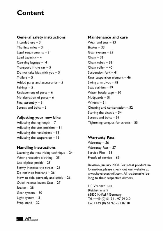
General safety instructionsIntended use – 3The first miles – 3Legal requirements – 3Load capacity – 4Carrying luggage – 4Transport in the car – 5Do not take kids with you – 5Trailers – 5Added parts and accessories – 5Fairings – 5Replacement of parts – 6No alteration of parts – 6Final assembly – 6Screws and bolts – 6
Adjusting your new bikeAdjusting the leg length – 7Adjusting the seat position – 11Adjusting the handlebars – 13Adjusting the suspension – 16
Handling instructionsLearning the new riding technique – 24Wear protective clothing – 25Use clipless pedals – 25Slowly increase the strain – 26Do not ride freehand – 26How to ride correctly and safely – 26Quick release levers, Seat – 27Brakes – 28Gear system – 30Light system – 31Prop stand – 32
Content
- HPVelotechnik
Maintenance and careWear and tear – 33Brakes – 33Gear system – 35Chain – 36Chain tubes – 38Chain roller – 40Suspension fork – 41Rear suspension element – 46Swing arm pivot – 48Seat cushion – 49Water bottle cage – 50Mudguards – 51Wheels – 51Cleaning and conservation – 52Storing the bicycle – 54Screws and bolts – 54Tightening torques for screws – 55
Warranty PassWarranty – 56Warranty Pass – 57Service Plan – 58Proofs of service – 62
Revision January 2008. For latest product in-formation, please check out our website atwww.hpvelotechnik.com.All trademarks be-long to their respective owners.
HP VELOTECHNIK
Bleichstrasse 5 65830 Kriftel / GermanyTel. ++49 (0) 61 92 - 97 99 2-0Fax ++49 (0) 61 92 - 91 02 18

thank you for buying a recumbent bike designed by HP VELOTECHNIK and congratulations on the purchase of yournew Speedmachine! With the Speedmachine, a high-qualitysports bike, you will enjoy many years of exhilarating ridingpleasure.
Your safety and your satisfaction are our main concern. On thefollowing pages, this manual will inform you about importantsafety issues as well as maintenance and care instructions.
Even if you have many years of experience with bicycles pleasedo take your time to read this manual carefully.Your recumbentbike is designed with the latest bicycle technology byHP VELOTECHNIK that partly needs special treatment and care.
In this manual you will find detailed instructions on how to optimize your Speedmachine to meet your demands and ridingstyle as well as your size and weight.
In addition to this, we have put together a collection of infor-mation on care and maintenance as well as special technical ad-vice from our engineers.
This guide helps you to keep your Speedmachine in perfectcondition so that you will always have maximum fun, comfortand safety.
Enjoy yourselves and have a great ride!
Paul J.W. Hollants, Dipl.-Ing. Daniel Pulvermüllerand the HP VELOTECHNIK team
1HPVelotechnik
Introduction
Dear customer,
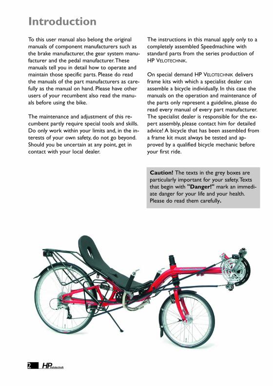
To this user manual also belong the originalmanuals of component manufacturers such asthe brake manufacturer, the gear system manu-facturer and the pedal manufacturer.Thesemanuals tell you in detail how to operate andmaintain those specific parts. Please do readthe manuals of the part manufacturers as care-fully as the manual on hand. Please have otherusers of your recumbent also read the manu-als before using the bike.
The maintenance and adjustment of this re-cumbent partly require special tools and skills.Do only work within your limits and, in the in-terests of your own safety, do not go beyond.Should you be uncertain at any point, get incontact with your local dealer.
The instructions in this manual apply only to acompletely assembled Speedmachine withstandard parts from the series production ofHP VELOTECHNIK.
On special demand HP VELOTECHNIK deliversframe kits with which a specialist dealer canassemble a bicycle individually. In this case themanuals on the operation and maintenance ofthe parts only represent a guideline, please doread every manual of every part manufacturer.The specialist dealer is responsible for the ex-pert assembly, please contact him for detailedadvice! A bicycle that has been assembled froma frame kit must always be tested and ap-proved by a qualified bicycle mechanic beforeyour first ride.
Introduction
2 HPVelotechnik
Caution! The texts in the grey boxes areparticularly important for your safety.Textsthat begin with "Danger!" mark an immedi-ate danger for your life and your health.Please do read them carefully.

Gen
eral
saf
ety
inst
ruct
ions
3HPVelotechnik
Legal requirementsWhen you ride your bike on the public road itmust comply with national legislation andguidelines.These will vary from country tocountry. In general, there are minimum stan-dards for brakes, reflectors and lighting sys-tems, as well as usually a general duty to en-sure that your vehicle is in roadworthy safecondition.There will also be a duty to ride in asafe and responsible manner. If you ride yourHP VELOTECHNIK bike in traffic you should besure to observe all the applicable laws and reg-ulations.
In most countries, including Germany and theUK, two independent braking systems are re-quired. Do not ride with only one brake work-ing!
Please contact your local dealer to find outabout your legal obligations.
General safety instructionsIntended useYour Speedmachine is a bicycle for the use onstreets and surfaced roads.
This bicycle is not designed for the use in rac-ing and off-road riding, for jumping or acrobat-ics, and you must not ride across curbs, stairs,etc.
Damage through inappropriate use, assemblyerrors, accidents or similar activities and wilfuldamage results in the loss of any warranty.
The intended use also includes the precise ob-servation of the prescribed usage and mainte-nance regulations and instructions.
The first milesThe first 300 km (186 miles) are an importantphase in which you break in the bicycle.During the first use of a new bicycle thescrews may bed in and come loose. Cables andspokes may stretch. Please be very attentiveduring that period.
After 300 km or after two months at the lat-est you will have to take your bicycle to a bi-cycle mechanic for the first service. Pleaserecord this first service and the tasks per-formed in the warranty pass on page 57.This first service is the prerequisite for furtheruse of the bicycle and for your warrantyclaims.

4 HPVelotechnik
Load capacityThe maximum load (rider + luggage) is 130 kg(286 lbs).The maximum total weight (bicycle +rider + luggage) is 150 kg (330 lbs).The lowerlimit is valid. It is important to adjust thespring stiffness of the suspension according tothe load, see the chapter about adjusting thesuspension in this manual, page 16.With an attached trailer, the maximum totalweight must not be higher than 150 kg (330 lbs).
Carrying luggageLuggage transport is only allowed with thespecial rear racks or lowrider racks offered byHP Velotechnik .The maximum load of therear rack is 25 kg (57 lbs), the maximum loadof the lowrider rack is 25 kg (57 lbs).
When a rear rack is mounted you have tomake sure that when the rear suspension isfully compressed there is at least a 1 cm (app.1/2") distance between the rear tire (or mud-guard) and the rear rack. In order to adjustthis distance you can clip spacers onto the pis-ton rod of the spring at the rear end betweenthe spring retention disc and the bottom-outelastomer.These spacers are available fromyour local HP Velotechnik dealer.You will findfurther information in the chapter on suspen-sion adjustment on page 20.
Additional loading can influence the handling ofyour bike considerably. If you plan on ridingwith heavy luggage we advise you to make atest ride on a street with no traffic to adjustto the new situation.
The load should be placed as close to thebody of the rider as possible, since this leadsto more stable performance.
You can also improve the handling of the bikeby positioning the center of gravity of the lug-gage as low as possible, so pack heavy items inthe bottom of your panniers and hang themon the lowrider racks.
Be careful that your luggage on the rack issafely stored. Bags must be tightly fastened tothe rack so they can not move. In no case mayloose parts like straps or belts touch thewheels, the derailleur or the suspension.
We recommend waterproof bicycle bags bythe German manufacturer ORTLIEB.You can buythem with extra large hooks matching theoversized tubes of the rack.You can also refitthose largs hooks later.
Take care that your luggage does not coverthe lighting system and the reflectors of yourbicycle and that they stay fully functional.
In case you want to park your bicycle takecare to lean it on a wall or any other solid ob-ject.With the kickstand alone it is not possibleto safely park a bicycle loaded with luggage, itcould fall down and be damaged.
General Safety Instructions

Gen
eral
saf
ety
inst
ruct
ions
5HPVelotechnik
Transport in the carThe best way of transporting your bicycle isinside the car. See that it does not lie on thederailleur.
If you want to transport it outside the car werecommend a roof-rack or a rear carrier.Takecare to fasten your bicycle at the frame only.
Please remove any part that could come looseduring transport (seat cushion, water bottles,luggage bags, pumps, pennants, etc.).
Do not take kids with youThe Speedmachine is not designed for thetransport of children.You are not allowed tomount a child's seat. It is only allowed totransport children in a trailer that has beenspecially designed for that purpose.
TrailersYou are allowed to use trailers up to 40 kg(88 lbs) with the Speedmachine.We recom-mend to assemble it with the WEBER-couplingType E.Always check that the suspension andthe trailer still work properly after you havemounted the trailer.Take care that the trailerdoes not damage the frame in case the bicyclefalls over.
Added parts and accessoriesAdditional accessories may impair the functionof your Speedmachine.We advise you to gen-erally ask your dealer before you mount anyspecial parts or accessories to your bicycle.
Take care that the handlebar and the suspen-sion always stay mobile.You may not add anyparts to the handlebar or the seat that mightendanger the rider through sharp edged orpointed shapes while steering, getting on andoff the bike or bumping against something.
Before you purchase a bell or a lighting systemmake sure that these accessories conformwith your national laws and regulations.
FairingsWe advise you against using front fairings forthe Speedmachine, since the high position ofthe bottom bracket impairs the vision over afairing to the front.
Please take into account that any fairing makesthe bicycle more prone to crosswind influ-ences. In strong wind or gusts of wind unsafesituations may occur, please take off the fairingin such weather conditions before the ride.
Caution! Do not fasten your bicycle at thehandlebar or, with disassembled wheels, atthe dropouts.The wind causes violent forcesthat can stress the parts and therefore maycause damage. Such a damage may not benoticed immediately.
Caution! Mounting additional parts or ac-cessories is at your own risk. It is importantthat you carefully read the installation guideof the manufacturer.Additions to the handle-bar like fairings, handlebar fittings, bottleholders etc. may impair your safety due toadditional loading or clips with sharp edges.

6 HPVelotechnik
Replacement of partsThe replacement of parts relevant for safety(especially brakes, light system, stem, handlebar,fork, drive train, suspension elements) shouldonly be done with original parts by a bicyclemechanic, since it requires a certain degree ofskill, suitable tools and mechanical aptitude.
Any technical change you perform on yourown is at your own risk!
No alteration of parts
Final assemblyYour bike has been delivered to your specialistdealer only partly assembled.
Your dealer has carefully finished the assembly,perhaps altered the specification of your biketo meet your special requirements and per-formed a test ride. Please make sure that thispre-delivery service is recorded in the warran-ty document at the end of this manual.
All screws must be checked and tightened, es-pecially on the handlebar, stem, fork, swing armpivot and wheels. Please follow the tighteningtorque settings listed in the table on page 55.
Rear derailleur and brakes must be checkedand adjusted. Please follow the instructions inthe manuals of the parts manufacturers thatcome with this manual.
Screws and bolts
General Safety Instructions
Danger! If any part is deformed (e.g. due toan accident or overload), especially frame,fork, handlebar, seat mounts, pedals, cranksand brakes, it is not allowed to use it anyfurther or repair it. Do not try to straightenbent parts.You must replace them for yourown safety. If you do not replace a damagedpart it can result in a total failure of the partand you may be seriously injured!
Caution! You are not allowed to performany work on the parts of the bicycle, espe-cially frame, fork, handlebar and seat, whichmight endanger their solidity.These works include drilling holes, welding,brazing, painting methods that add heat orany other chemical treatment. If any of theseworks is done improperly it may result in aloss of strength through direct damage orincreased susceptibility to corrosion.
Caution! Screws must be tightened withprescribed tightening torque. In this manualtightening torques are given in Nm(Newtonmeter).Always use a torquewrench wherever a torque setting is given inthis manual. Never rely on "feel". Screwstightened too much or not enough canbreak, which can lead to dangerous acci-dents. In case you don't own a torquewrench have your bicycle mechanic do therespective work.You will find a table withthe prescribed torque settings on page 55 inthis manual.
Adj
usti
ng y
our
new
bik
e
7HPVelotechnik
Before the first ride: adjusting yournew SpeedmachineThe seating position is essential for your ridingcomfort, well-being and efficient cycling on theSpeedmachine.Therefore you should adjust theframe, seat, handlebar and suspension to yourindividual requirements.
In order to adapt the Speedmachine as closelyas possible to your body dimensions and tofind the ideal seating position you need to ad-just the front boom, seat and handlebars.
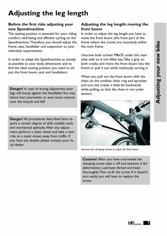
Adjusting the leg length: moving thefront boomIn order to adjust the leg length you have tomove the front boom (the front part of theframe where the cranks are mounted) withinthe main frame.
Unscrew both screws M8x35 under the maintube with an 6 mm Allen key.Take a grip onboth cranks and move the front boom into theframe or pull it out while cautiously turning it.
When you pull out the front boom shift thechain on the smallest chain ring and sprocketand turn the cranks a little bit backwardswhile pulling, so that the chain is not undertension.
Adjusting the leg length
Danger! In case of wrong adjustment yourlegs will bump against the handlebar.You mayhence hurt yourselves or even loose controlover the bicycle and fall!
Danger! All procedures described here re-quire a certain degree of skill, suitable toolsand mechanical aptitude.After any adjust-ment perform a static check and take a test-ride on a quiet street, away from traffic. Ifyou have any doubts please contact your lo-cal dealer.
Caution! After you have unscrewed theclamping screw take it off and examine it fordeformation. Lubricate thread and headthoroughly.Then re-fit the screw. If it doesn'tturn easily you will have to replace thescrew.
Unscrew the clamping screws to adjust the front boom.

8 HPVelotechnik
In order to check the adjustments have anoth-er person hold the bicycle while you are sit-ting on the recumbent.
Adjust the front boom in such a way that yourleg is fully extended when your heel (wearingflat shoes) is in the foremost position on thepedal. Experience shows that the pedal-to-seatdistance on a recumbent can be slightly longerthan on a conventional bike.While you arepedaling the ball of your foot should be posi-tioned over the center of the pedal axle. It isimportant that your leg is not fully straight-ened when the crank is in the foremost posi-tion. If the distance is too great it is difficult toovercome this dead point, pedaling becomesuncomfortable and there is too much strain onthe sinews of your feet and legs. If the distanceis too short you may suffer from knee pain oryour legs bump on the handlebar.
For riders with a short leg length the frontboom has to be cut by a bicycle mechanic, sothat it can be inserted to the maximum. It isimportant to trim the end of the tube neatly.The bare metal of the shortened tube end hasto be protected against corrosion with a paintstick or wax spray.
Adjust the front boom so that the bottombracket axle is horizontal when you look at itfrom the front. For that purpose look beyondthe bottom bracket shell at the rear wheelaxle and align the front boom parallel to it.Align your eyes with the bottom bracket axleand not the front changer tube above.Then siton your bicycle and check the position.(Hint:When you have the impression that thebottom bracket is turned alternately to theleft and then to the right when cycling you willhave found the correct middle position).
Tighten the screws with a torque wrench. Onyour first ride check whether there is suffi-cient clamping.
Adjusting the leg length
Caution! When you move the front boomtake care that its end does not damage thelight cable that possibly comes out of themain frame near the fork. Speedmachinescan be ordered with varoius front boomlengths. Please inform yourself about thelength of the front boom on your bike be-fore you do any work.While moving thefront boom you also have to move the cablefor the front derailleur in the tube or take itout.The light cable must never be stressedby pulling.
Adjust the front boon so that your knee will not be fully straight-ened when pedaling.
Danger! When you insert the front boom,the front boom and the inner wall of thetube must be totally free from grease, other-wise it won’t clamp properly and turn whileyou are riding.

Adj
usti
ng y
our
new
bik
e
9HPVelotechnik
Caution! The minimum insertion depth ofthe front boom into the main frame is 10cm (4"). In no case may the end of the frontboom be visible in the clamping slot whenyou look at the main frame from below,since it may result in a damage of the frame.
Danger! In the opening of the main framethere must be a spacer (a slotted tube ofblack plastic with edges to the front and theclamping slot) that is glued into the frame.This spacer ensures safe clamping of thefront boom and protects the paint. It is im-portant that you take care that this spacer isalways visible at the front end of the mainframe.The lower slot has to be aligned inaccordance with the slot in the main frame.If this spacer is missing or is moved to theback of the tube while inserting the frontboom, secure clamping is no longer guaran-teed, even if it seems to be the case at firstglance. If the front boom is not clampedproperly it may turn and lead to a fall.Amissing or misaligned spacer will lead to aframe damage.
The rear end of the front boon may never be visible in theclamping slot.
The plastic spacer between front boom and main frame must bevisible at all time.
Danger! If the screws are tightened toomuch or bent, the screw or the frame canbreak! If the clamping is insufficient the frontboom can turn during a ride which maycause your feet to slip from the pedals andlead to a dangerous fall.
If the spacer is missing or not alligned properly or the screws aretightened too much, the frame can break.!

10 HPVelotechnik
In order to move the bottom bracket tubeyour specialist dealer has to adjust the chainlength. By default the Speedmachine comeswith a very long chain so that the adjustmentrange of the bicycle can be fully used withoutthe need to lengthen the chain.
After the first adjustment of the leg length thatyou have done together with your specialistdealer while handing over the bicycle, thechain has to be shortened so that the arm ofthe derailleur is not fully turned forward whileshifting on the big chain ring in front and thebig sprocket behind.The derailleur must stillbe able to compensate a length change of thechain of at least 4 cm. In order to choose theright chain length please consult the manual ofthe derailleur manufacturer.
After you have adjusted the front boom youshould seal the gap in the clamping slot be-tween the front boom and the main framewith wax or silicone in order to protect yourframe from the penetration of water and dirtand hence damage through corrosion whichmay lead to a broken frame. (The clampedtube has to stay grease free, see above).
We recommend you to slightly readjust thefront boom every 3 months so that knees,muscles and ankles will be used differently, andyou might find a more comfortable and moreefficient riding position.
A wrong adjustment may lead to pain in yourknees and inefficient pedaling. In addition werecommend to ride with a high pedaling ca-dence, which means to pedal fast and with lit-tle pressure. Pedaling with too much pressuremay also lead to pain in the knees.You will findmore information about this on page 26.
Adjusting the leg length
Danger! After the chain has been short-ened it has to be closed with a special clos-ing link or a chain riveting tool that expandsthe rivet while riveting (i. e. ROHLOFF-Revolver).A poorly joined chain may breakand thus lead to a fall. Have adjustments ofthe chain length or the changing of the chainbe done by your bicycle mechanic.
Check that thre is at least a 5 cm (2")clearance between theend of the chain tube and other parts of the drive train.
Caution! Take care that the chain tubeshave at least a clearance of 5 cm (2") to therear derailleur and the front changer evenunder maximum tension of the chain andthat the tubes stay tight in their fastenings.The front upper tube can be moved to therear for length adjustment. Shorten thetubes if necessary. If the end of the chaintube gets into the rotating drive train itcould be locked-up and destroyed.The endof the chain tubes have to be tightly securedwith a rubber tube over the retentionspring.

Adj
usti
ng y
our
new
bik
e
11HPVelotechnik
Adjusting the seat positionAdjusting the seat lengthYour Speedmachine is equipped either withthe ErgoMesh® mesh seat or the adjustableBodyLink® seat from HP VELOTECHNIK.
The following instructions refer to theBodyLink seat. Length, seat back angle andlower seat angle are adjustable for this seat.The adjustment of the seat length and theproper seat angle is crucial for a comfortablefeeling while riding your recumbent.
The upper curve of the seat back in the areaof the shoulder blades determines the correctseat length:Through this shape the shoulderand neck area is lifted from the recumbent po-sition so that the head rests in a natural andrelaxed position. For this reason you shouldn'tneed a head rest if you have the right seat po-sition. On long rides, a head rest can increaseyour riding comfort as you can relax yourneck for a few seconds by leaning back.Youcan mount our custom headrest to your exist-ing seat.The seat is too small when you have the im-pression that your back is pressed too muchinto a "hunchback". It is too large when youhave the impression that the seat angle is toofar back when you are in the most upright po-sition, or when you hit the upper seat edgewith the back of your head when you look up-wards.
Adjusting the seat lengthTake off the seat cover (see page 49). Openthe quick release lever for the seat back angleadjustment, so that the seat is not bent withinner tension. Loosen the 4 screws at the in-ner side of the seat back with an allen keySW4 a few turns. Step behind your bike andhold the seat back with both hands. Pull orpush the seat back to achieve the preferredseat length.To achieve the smallest possibleseat length, move the 2 upper screws from thetop to the middle holes.
Tighten all 4 screws with 5–6 Nm. Move theseat back rest to the preferred angle and closethe quick release lever firmly. Reinstall the seatcover
Length adjustment of the Airflow cushionThe optional Airflow-cushion consits of twoparts, that connect in a V-type shape. Loosenthe velcro mount of the upper part, and placeit in the desired position, than fasten the vel-cro.
Adjusting the seat back angleA big advantage of the BodyLink® seat on yourSpeedmachine is that you can adjust the seatback angle very quickly. For beginners or ridesin the city you can choose an upright seat po-sition for a better view, and for longer ridesyou can choose a flat position for better aero-dynamics.
The seat back is fastened with a quick releaselever on a slotted aluminum seat mount.Youcan adjust the seat back angle by 10 degreesby simply opening the quick release lever. Inthe medium seat position the angle is about35° from horizontal.
Caution! Do not loosen or tighten the 4screws in the lower seat part to adjust theseat length. Maximum tightening torque ofthese screws is 3–4 Nm.
Caution! To avoid noise from the seat whenloaded, the contact surfaces between thetwo seat halfs need to be seperated by self-adhesive plastic sheets and all contact sur-faces of seat and seat mounts and frameneed to be lubricated with grease.

12 HPVelotechnik
Adjusting the seat positionAdjusting the seat back angle is easy when youpush the seat closely to the seat mount intothe desired position. By pulling at the upperseat edge, you would twist the seat, creatingtension and locking up the adjustment mecha-nism.
Because of the flexibility of the BodyLink® seatand the special cam shape of the seat mounts,the seat effectively pivots around a central ax-is, approximately in the area of the lower lum-bar vertebrae.This is the place where you sup-port the biggest part of your pedaling forcewhile riding, so this point determines the dis-tance to the pedals.The advantage of this de-sign is that you adjust the distance from theseat to the bottom bracket only once as de-scribed above, a change in the seat angle doesnot require an adjustment of the front boom.
Adjusting the front seat edgeThe front seat edge can be slightly lowered toaccommodate smaller riders.With a lowerfront seat edge, it is easier to put your feet onthe ground without pressure from the seatedge on the back of your legs.With a higherfront seat edge, the seat will give more sup-port and avoid the feeling of „sliding down theseat“ that occurs with upright seat angles.
To adjust the front seat edge, open the quickrelease lever at both the lower and the upperseat half, so that the seat has no inner tension.Thus you need less force for the adjustment.Push or pull the seat front edge firmly untilyou reach the desired position and close thequick release lever firmly.Then adjust the seatback angle as described above.
If the quick release lever pressure is to loosewhen closed, open the lever and turn thescrew on the end of the quick release axleclockwise.The low profile design of the screwhead gives more clearance for the drive train.
Adjusting the lumbar supportThe BodyLink® seat is ergonomically shapedand supports the natural S-curve of yourspine. Forces from pedaling are supported inthe area of your lower back just above yourhips.The amount of support in this area (lum-bar support) is adjustable by moving the seatback and lower seat opposite to each other.
To get more lumbar support, lower the seatfront edge and put the seat back in a more re-clined position.To get less lumbar support, rise the front seatedge and put the seat back more upright.For more extreme adjustments, loosen the 4screws for the seat length adjustment in theseat back.Thus the seat back can expand andbend into the desired shape.Tighten thescrews and quick releases as described above.
Height adjustment of the head restThe BodyLink® seat can be fitted with an op-tional head rest.The head rest cushion is at-tached to the flexible mount with velcro tape.You can adjust its height within an inch, so thatit fits under the edge of your helmet The cush-ion should support your upper neck and lowerhead when leaning your head back.
Caution! The three quick releases have tobe closed firmly (tightening force 15-20 kg /45 lbs) to safely hold the seat.You are notallowed to open them while riding.Afterthey have been closed the imprint "close"must be visible. If the quick releases are nottightened appropriately the seat can movewhile riding so that you may no more beable to control your bicycle.
Caution! Do not push or carry your bikeon the head rest, this could damage thehead rest or your seat!

Adj
usti
ng y
our
new
bik
e
13HPVelotechnik
Adjusting the Above Seat SteeringTwo versions of handlebar layouts are avail-able:Aerobars to the front or tiller steering tothe rear.
The handlebar is connected to the fork by astem that is adjustable in length.The stem hasthree clamping connections where the tubesare slotted and connected with a clampingscrew.The connections are in particular theconnection stem/fork, the connection of theupper half of the stem with the lower part ofthe stem for telescopic adjustment of thelength, and the connection stem/handlebar (inother words, all 3 screw connections at thestem).
Danger! Every time you undo one of theclamping connections you have to check theclamping screw.You also have to check thewelded-on thread nut.The thread must notbe damaged and the screw must turn easily.Once a year you have to dismount thescrew completely and check it. In case ofdamage or deformation you have to changethe clamping screw immediately.When yourefit the screw it has to be lubricated care-fully and tightened with the required tighten-ing torque (see table on page 55).
In case you tighten the screws too much theclamping may deform and break.When youbend the screws while tightening they maybreak and the clamping can loosen.Whenyou tighten the screws with an insufficienttightening torque the clamping does notreach the necessary strength and this canresult in a twisting of the handlebar or thestem while riding.All these assembly errorscan lead to dangerous falls!
Adjusting the handlebars
On the stem you will find 3 clamping screws for adjustment.
At first align the stem parallel to the frontwheel. For this purpose loosen the lowerclamping screw M8 with an Allen key SW6.Get on your bike, secure the front wheel withyour feet and bring the stem into line.Tightenthe screw with a tightening torque of 13-14Nm. Check the safe clamping by trying to twistthe stem against the front wheel. Due to themanufacturing process the upper end of theshort tube which is attached to the fork'ssteerer tube is slightly oval, this is not a defect.
With the tiller steering, the grips of the han-dlebar should show to the front in riding di-rection, away from the rider.This results in themost comfortable position to grip the handle-bar since all you have to do is "hook in" yourhands to the handlebar.This position allows foreasy cornering as it gives the rider the mostspace between handlebar and belly.
The adjustable stem should preferably be setto the shortest possible position while takingcare that the legs don't touch the handlebarswhen riding. For that purpose mount your bi-cycle after you have adjusted the leg length asdescribed above. Loosen the clamping screw alittle bit until you can adjust the length of thestem.

Adjusting the under seat steeringhandlebarsYour GrassHopper with under seat steering isequipped with an „indirect“ steering.The han-dlebars are supported by a stem that pivots inthe frame.The front fork is connected with asteerer rod to the stem.
Horizontal alignment of the handlebarsThe stem is made of two parts that telescopi-cally slide into each other.The connection ismade by 2 clamping screws. Loosen bothclamping screws, sit on the bike and align thehandlebars horizontally, so that both bar endsare at same height.Tighten both clampingscrews with 8–10 Nm.Check the safe clamping by trying to turn thehandlebars in the stem.This should only bepossible with high forces.The ability to turn isdesigned on purpose: In case the bike dropsover the handlebars can turn without beingbent or broken immediately.
We suggest to fully insert the stem half. If youmove the handlebars further back, you will in-crease your turning circle as the handlebarwith contact the frame or lowrider earlier.
Alignment of the handlebars to the wheelRemoove the screw between rear steering rodend and stem. Loosen the counter lock nut atteh rod end.Adjust the steering rod length byscrewing the rod end in or out to align thehandlebars perpendicular to the front wheel.Adjust both rod ends parallel to each other.Tighten the counter lock nut against the steer-ing rod with 8–10 Nm.Position the rear rod end on top of the mountat the stem and reassemble the screw and self-securing nut with 8–10 Nm. Check the correct
14 HPVelotechnik
Pull the handlebar with the upper part of thestem towards yourself so that there is enoughroom between your thighs and the handlebarfor pedaling.Then check the clamping screw asdescribed above and tighten the screw.
Tightening torque for the screw M6 (Allen key5 mm ) 8-10 Nm.
Adjusting the handlebars
Danger! Only pull out the stem so far asnot to fall below the minimum insertiondepth of 4 cm (13/4"). In no case may thelower end of the inserted tube be visible inthe clamping slot! When the stem is pulledout too far the clamping may be damaged orthe stem may come loose while riding,which can result in a dangerous fall.
The end of the upper stem half must not be visible in the clamp-ing slot.
Danger! The minimum insertion depth ofthe stem half is 5 cm (2"). In no case maythe rear end of the inserted stem half be-come visible in the clamping slot.

assembly of the indirect steering by turningthe handlebars in both directions untill thehandlebars make contact with frame.The rodends must moove freely without hitting theframe or getting twisted.
Adjusting the handlebar angleBy changing the angle of the handlebars youcan adjust the position of the grip to thelength of your upper body and your arms.
In order to change the angle, loosen thescrews of the handlebar clamping.Turn thehandlebars until they are in your favourite po-sition. Check that the stem clamps the handle-bars exactly in the middle.Tighten the clamp-ing screws with 8–10 Nm. Check the correctclamping of the handlebars by mounting yourbike and pulling the handlebars. In doing so thehandlebar grips must not turn.
Please take care that the clamping area of thestem is thoroughly trimmed and does not haveany sharp edges which may lead to a ruptureof the handlebars.
While riding you should allow your arms torest in a relaxed position on the handlebars.Do not pull on the handlebars. If the handle-bars turn in the stem clamping during the ridestop immediately and tighten the clampingscrew of the handlebars.
Adj
usti
ng y
our
new
bik
e
15HPVelotechnik
Danger! The adaptor for the connection offront rod end and front fork must be seatedfirmly in the slots of the outer steering tubeand be firmly secured between adjustmentring and counter lock ring. Before everyride, check that there is no play in the steer-ing system. Play will destroy your front forkand lead to unsecure riding conditions.
If the handlebars turn in a stem that is not suf-ficiently clamped the handlebars or the stemmight be damaged or deformed. In that case asecure clamping can no longer be guaranteed,even with the correct tightening torque, andhandlebars and stem have to be exchanged.
Adjusting the cable length
You can make smaller adjustments by movingthe cables in their guides at the frame and thestem, so that there is enough room at all mo-bile parts. If this proves not to be sufficientyou will have to have your specialist dealershorten the cables or replace them by longercables.
Cover all contact areas where cables moveand touch the frame with sturdy transparenttape.This protects the paint against scratchingand wear.
Handlebar gripsThe grips on the handlebar are susceptible towear and tear. Have your grips replaced byyour bike shop once they don't feel comfort-able anymore.The grips always need to be at-tached firmly to the handlebar.
Caution! After you have adjusted the han-dlebar position you have to adjust the lengthof the brake cables and shifter cables.Thecables have to run smoothly without anysharp turns and they may not be bentsharply or stretched when the handlebar isat maximum cramping or the above seatsteering stem is folded forwards. Also avoidlarge arches that could be caught up in oth-er parts.

16 HPVelotechnik
Purpose of the adjustment of the su-spensionYour Speedmachine is fitted with a suspensionfork for the front wheel and a rear swing armfor the suspension of the rear wheel.This sy-stem compensates slight bumps on the roadso that riding is comfortable and the strain onyour bicycle is reduced.
A well-adjusted suspension improves the trac-tion of your bicycle on uneven roads.Especially when riding in a bend this allows ahigher speed and also improves the safety.
In order to achieve maximum riding comfort,the suspension settings have to match yourweight as well as the road condition.
The goals of the adjustment are:
● maximum use of the available suspension travel without the suspension frequently bottoming out
● quick reaction of the suspension without obvious oscillation after having passed a bump
● avoiding self enforcing oscillations, that meansincreasing oscillations of the suspension system due to pedaling influence, rhythmic body movements or permanent wavy under-ground
Suspension and dampingThe suspension systems of the suspension forkand the rear swing arm are fitted with the ac-tual springs and dampers which are mountedseparately. Often, the terms suspension anddamping are used inappropriately in everydaylanguage.
The spring is the elastic element that com-presses and decompresses through the loadwhich occurs on bumpy roads.While decom-pressing the spring releases the same energy ithas saved during compression.
The Speedmachine is fitted with coil springs ofsteel at the suspension fork and the rear forkswinging arm.The optional rear shock DT-SWISS XM180 uses air as spring medium.
The damper slows down the process of com-pression and decompression.That means thatthe bicycle after having passed a bump doesnot immediately "spring" back to the initial po-sition or even further than that.The damperconverts spring energy into friction and finallyinto heat, and thus takes away energy from thesuspension system.That way the damper pre-vents that the spring swings uncontrolled afteran initial stimulation. In addition the damperhelps to avoid self enforcing oscillations of thesuspension that may be caused by reoccurringstimulation like pedaling forces within a crankrevolution or the rhythmic up and down mo-vement of the legs.
The suspension fork of the Speedmachine isdampened through a friction damper in thefork, the rear suspension through a hydraulicdamping unit. Some models have an adjustabledamping.
Adjusting the suspension

Adjusting to loadThe luggage rack of the Speedmachine ismounted to the suspended part of the frame.That way your luggage is also fully suspendedand it spares the material. Most notably, evenunder heavy load the suspension will compen-sate an uneven road much better and quickercompared to a design where the luggage car-rier would be mounted to the unsuspendedparts, e.g. the rear swing arm.
Additional luggage changes the load of thewheels and their suspension.The suspensionsare more compressed through the load.Thatway, there is less suspension travel for bumpswhile riding.Your suspension could seize upmore often.
The suspension of the front wheel is less affec-ted since luggage at the rear rack almost onlyputs weight on the rear wheel.
In order to compensate the variations in theload you can change the pre-load. For detailssee the following chapter.
Theoretically this can compensate for a loadchange of approx. 10 kg (23 lbs) at the rearwheel. In case of higher variations in the loadyou would have to exchange the spring for an-other spring with another spring stiffness. Inpractice you can often do without it: theSpeedmachine offers with 60 mm a lot of su-spension travel for a sports bike.When youchoose the spring stiffness so that the full 60mm are at your disposal when your recumbentis under maximum load, you will have a so-mewhat smaller but still very comfortable su-spension travel when you ride without luggage.
The optional air shock DT-SWISS XM180 canbe easily pumped up to compensate load incre-ases.
Adj
usti
ng y
our
new
bik
e
17HPVelotechnik
You should always set the damping as low aspossible to give the bicycle the possibility toquickly react even to several bumps in a row.
You can ride the Speedmachine with a consid-erably lower damping than for example a MTB:due to the relaxed and steady position of thebody the recumbent does not experience ex-treme variations in the load as it is knownfrom dancing on the pedals while riding uphillon a mountain bike.
In addition to this, varying pedaling forces havevery little influence on the suspension of thebicycle due to the No Squat design of the sus-pension system of the Speedmachine. So whenyou adjust the damping, always start with a lowdamping.
It is necessary to choose the correct springstiffness to have a well operating suspensionsystem.The spring stiffness is a measure forthe compression of a spring at a certain load.It is either given in "N/mm" (Newton perMillimeters) or "lbs./inch" (Pounds per Inch).Sometimes you only find "lbs." printed on thesprings.
The spring stiffness of the optional air shockDT-SWISS XM180 is set by adjusting the airpressure.
The suspension is designed in a way that thespring compresses considerably when youmount your bicycle.This is called negative sus-pension travel (or "sag") and enables the bicy-cle to decompress on bumpy roads. (Which isin fact a definitely positive feature.) You shouldchoose a spring stiffness with which this nega-tive suspension travel takes up around 30% ofthe overall suspension travel.This value usuallyprovides a very comfortable ride on your fullysuspended recumbent bike designed by HPVelotechnik.

18 HPVelotechnik
Caution! When you turn the cap take carethat it is always screwed into the outer tubewith at least 5 complete turns.To check un-screw the cap completely anti-clockwise.Then put the cap back on the outer tubeand tighten it at least by 5 threads. In nocase may the threaded lower end of the capbe visible.This thread passes on the totalload of the front wheel to the frame. In caseyou don't take care of the minimum thread-ed depth the thread can come off and de-stroy your fork permanently.
Do not turn the cap as far as it will go intothe outer tube, there has always to be asmall gap of at least half a turn.Thus youhave an adjusting range of 3,5 turns.
Adjusting the suspension: suspension fork
Adjust the damping to the smallest value pos-sible.That way the fork reacts sensitively andstable. In case of heavy damping the suspensioncan rub and compress not as smoothly as withlow damping.The up and down movement ofthe legs while pedaling can make the fork os-cillate at certain pedaling frequencies and cer-tain leg lengths; you can reduce this influenceby choosing a stronger damping.
Caution! After having adjusted the dampingyou have to tighten the lower clamping ofthe stem as described in the chapter"Adjusting the handlebar", see page 13.
Adjusting the suspension forkThe front fork of the Speedmachine comeswith a "Concept S2" suspension system.Thesuspension travel is about 54 mm.The forkfeatures a simple adjustment of the dampingand exchangeable steel springs.
Adjusting the damping of the suspensionforkTo adjust the damping you turn the threadedcap at the upper end of the fork.The dampingresults from friction between an elastomerring that lies between the outer tube and theinner fork steerer tube. By tightening the capthe elastomer ring is compressed, the frictionto the side walls of the inner fork steerer tubeis increased and thus gives more damping.
Both compression and rebound damping areaffected at the same time by turning the cap.
In order to adjust the damping you have to un-do the clamping screw of the stem.Afterwardsyou can turn the cap either by hand or with ahex nut (12/13 mm). If you look at it fromabove the damping increases while turningclockwise, it decreases while turning anti-clockwise.
After unduing the stem clamping, you can adjust the damping.

Adj
usti
ng y
our
new
bik
e
19HPVelotechnik
If the spring stiffness should not meet your re-quirements you can order a spring with anoth-er spring stiffness through your dealer andhave it mounted there.
For more information for your specialist deal-er on changing springs, see "Maintenance andCare" on page 41.
You can distinguish the dismounted springs bytheir color:
medium, 18-20 N/mm: blackhard, 20 N/mm, red
(Valid for Concept-Suspension from 10/2005on)
Choosing the spring stiffness of thesuspension forkYour suspension fork comes standard with amedium spring that covers a wide range ofload and riding styles.The pre-load is fixed toabout 3 mm.
In order to follow our advice for about 30%compression of the suspension while mountingthe bike (negative travel) , the suspensionshould compress by 14-18 mm.To check thisvalue you will need a second person and aruler. First measure the distance between forkand frame.
Let the second person hold the bicycle whileyou mount the bike and put your feet on thepedals. Have the second person now measurethe distance at the same spot.
The value taken should be smaller by 14-18mm than the value taken before. Repeat thisseveral times and calculate an average value.Due to the stiction caused by the frictiondamping of the fork and the low pre-load thefork will not always spring back to its initialposition when compressed by hand. However,it will while you are actually riding and the fullsuspension travel is used.
Measuring is easier when you set the dampingof the suspension fork to a small amount.
It is not important to exactly follow the rec-ommended values for the negative travel,rather follow your feeling how the bicycle be-haves during a ride, depending on the road sit-uation.While riding you should only seldomfeel the suspension bottoming out. However, incase this never occurs the spring might be tohard which means you don't use the total sus-pension travel.

20 HPVelotechnik
Adjusting the suspension: rear swing armAdjusting the rear suspension ele-ment
For the rear suspension of the Speedmachinea spring element is combined with a hydraulicdamping unit in a suspension element.Thedamping results from fluid friction of an oilflow through thin holes of a throttle valve inbetween two chambers inside the damper.Aslightly noticeable sound that may occur fromthis oil flow is normal. Due to the fluid frictionthe spring element may heat up, thereforetouch the spring element after a ride very ca-refully.
The Speedmachine comes standard with asteel spring rear shock DNM DV-22.As an op-tion you can get the air shock DT-SWISS
SSD225 that uses air as spring medium.
Danger! While adjusting the rear suspen-sion element never load the bicycle e.g.through resting on the seat or loading therear rack when your hands or tools are clo-se to the suspension element. Otherwiseyour hands may get caught and squeezedwhen the suspension compresses.
Danger! The suspension elements are filledwith gas under high pressure. Never try toopen the damper or to remove the screw atthe gas tank. Inside the damper there are nouser serviceable parts. In case of damageyou will have to take the complete suspen-sion element to your dealer.
Steel spring rear shock DNM DV-22The pre-load determines how far the suspen-sion compresses when you are sitting on thebicycle while standing still.
For the rear wheel the same guidelines as forthe suspension fork are valid: for maximum ri-ding comfort the suspension should compressby about 30% of the total suspension travelwhile you mount the bicycle in driving posi-tion.
For that purpose measure (similar to the me-thod described for the suspension fork) the di-stance between the two suspension elementbolts or between rear rack and rear wheelwhile the bike is unloaded as well as while sit-ting on the bicycle in riding position.Also takeinto account possible luggage. Find out the to-tal suspension travel possible for your bicycle,depending on the mounted add-on-parts andclips on the piston rod.The static compressionshould amount to about one third of the ove-rall suspension travel.
You can affect this negative suspension traveldepending on how much you weigh and howmuch you load your bike either by adjustingthe suspension pre-load for fine tuning or byreplacing the spring with a spring with a diffe-rent stiffness in the rough tuning.
In order to adjust the suspension pre-loadturn the knobby adjustment ring on the threa-ded part of the suspension element by hand.Turning the adjustment ring clockwise (lookingat it from behind) reduces the preload, turningit anti-clockwise you screw the adjustmentring towards the spring and increase the su-spension pre-load. It is helpful to turn thespring together with the adjustment ring.

Adj
usti
ng y
our
new
bik
e
21HPVelotechnik
The adjustment ring should be turned no mo-re than five turns (measured from the relaxedposition) towards the spring. If the suspensioncompresses still too far even after six turns,the spring is too soft and has to be replacedby a harder spring.A too big pre-load of a toosoft spring does not take advantage of the fullcomfort potential.
You will find more information on changingsprings in this manual under "Maintenance andCare", page 45.
Suspension element DV-22 with fixed damping rate.
Danger! The adjustment ring has always tobe screwed so far towards the spring thatthe spring has no play when unloaded.Otherwise the adjustment ring could comeloose through shocks while riding so thatthe slotted rear spring retention disc comesoff. In that case the suspension element maybe damaged or the rear wheel could hit theframe or rear rack, which may lead to se-rious falls.Always have an initial pre-load of at least halfa turn on the spring. The suspension travel is adjusted by adding clips to the piston
rod of the spring element.
Danger! Take care that the rear wheel ormudguard or suspension element never hitthe frame, seat, rear rack or luggage boxwhile the suspension is fully compressed.
Therefore relax the spring completely byturning the spring retention disc on thethread of the spring element as far as it willgo (before this, push the possibly existing sa-fety spring ring from its slot in the threadedsection as far as it will go). Have a secondperson mount the bicycle and make the su-spension bottom out by leaning on the seator the rear rack.If the distance between the wheel or mud-guard and the frame or rear rack orSpeedbag is smaller than 1 cm you will haveto mount an additional spacer. In case youdon't, the mudguard may break suddenly orthe rear wheel might be blocked which canlead to serious crashes.

22 HPVelotechnik
Adjusting the suspension: rear swing armAir shock DT.SWISS XM180Please follow the instructions in the separatemanual from the rear shock manufacturer.
This rear shock contains pressurized air in amain („positive“) air chamber as suspensionmedium.Air shocks are lighter than steelspring rear shocks.Another advantage is thatthe spring stiffness can be easily adjusted withan air pump: By increasing the pressure thespring becomes harder.
Air shocks have a progressive spring behaviour,whereas steel springs have a linear spring be-haviour.This means that the air shock getsprogressively harder, e.g. it is much stiffer whenfully compressed than when only slightly com-pressed.
The advantage of this progressive spring be-haviour is the good bottom-out protectionwhen heavily loaded.
The valve for the air chamber is located at theback end of the air shock.The valve is protect-ed by a metal valve cap.
To pump up the air shock you need a specialair pump designed for bicycle air shocks. Itmust have a fitting schrader valve adaptor anda pressure indicator.
When attaching or removing the pumpto/from the valve, you will loose some air(about 0,5-1 bar).Take off the pump quickly.
Recommended pressure settings
load pressure – 80 kg (183 lbs) 7,5 bar –100 kg (230 lbs) 9,0 bar –130 kg (286 lbs) 10,5 bar
Maximum allowed pressure is 18 bar.
Danger! Take care that the rear wheel ormudguard or suspension element never hitthe frame, seat or rear rack box while thesuspension is fully compressed.
Therefore fully deflate the air shock. Have asecond person mount the bicycle and makethe suspension bottom out by pushing onthe seat or the rear rack.
If the distance between the wheel or mud-guard and the frame, seat or rear rack issmaller than 1 cm you will have to have yourbike dealer mount an additional spacer in-side the air shock. In case you don't, themudguard may break suddenly or the rearwheel might be blocked which can lead toserious crashes.

Adj
usti
ng y
our
new
bik
e
23HPVelotechnik
Adjusting the dampingBy adjusting the damping you can adjust theperformance of the suspension precisely toyour individual riding situation.A rough streetwith many harsh bumps that occur in a row oreven cobblestones needs a low damping ratewhile a road with long stretched bumps thatoccur more regularly needs a stronger damp-ing to achieve a smooth road holding.
When you add a lot of luggage you will needto adjust the spring stiffness; in that case anadjustment of the damping may even give youmore riding comfort.
Finally, the oil used in the damper becomesthicker and more viscous at lower tempera-tures, which can be compensated through achange in the damper setting.
Please note that you can seriously spoil theriding comfort through a bad damper setting,especially through unsystematic playing withthe knobs that may result in much to highdamper values. In the worst case the suspen-sion element will neither compress nor de-compress. If you are in doubt please consultyour local dealer.
The rebound damping prevents an eventual"jumping" of the rear wheel and provides agood traction. By improving the road surfacecontact the suspension of the GrassHopper al-so increases your riding safety.
A higher damping value prolongs the time untilthe decompression movement is finished. Onlythen can the suspension compensate the nextshock with the full suspension travel.Therefore, when you ride on very bumpystreets with shocks that occur fast in a rowyou might want to use a lower damping value.
A good setting for maximum comfort isachieved when the rear wheel decompressescompletely after a shock and then oscillatesonly once. In order to check the adjustmentyou will need a second person that compress-es the suspension by pushing the bicycle downwhile you are sitting on the bicycle in the rid-ing position.The other person can then ob-serve the suspension movements.
In order to adjust the damping during decom-pression, turn the adjustment knob on top ofthe rear end of the suspension element.
If you turn the knob in direction of the „-“ youwill get less damping and thus faster decom-pression.Turning the knob in direction of the„+“ will give you more damping and thus slow-er decompression.
Air Shock DT-Swiss XM180 Damping ist adjusted with the redknob at the rear end.The shock must be installed with the lock-out lever facing down to avoid a collision of lever and framewhen the suspension is moving.

24 HPVelotechnik
Learning the new riding techniqueYour new bicycle has been assembled by yourdealer and adjusted together with you as de-scribed on the previous pages under"Adjusting your new bicycle". Before youmount your bike and enjoy your first rideplease make yourself familiar with the instruc-tions on the riding technique and the handling.
To ride this recumbent you will have to makeyourself acquainted with the different ridingposition. Make sure that you and all other fu-ture users of this bicycle will have read thismanual carefully prior to the first ride. If youare in doubt please consult your local dealer.
Before the first ride the users of this recum-bent have to practice and make themselves fa-miliar with the different handling.We recom-mend to practice on a quiet road away fromtraffic. Before you ride the bicycle in traffic youmust master the handling completely.
Go to a road where you can ride straightahead without being hindered. Hold your bikeat the handlebar and pull a break.Then mountyour bicycle and lean back. Leave one foot onthe ground and put one on the pedal.Therefore rotate the crank in the top positionso that you can pedal immediately with power.
Try to keep your balance in that position.Assure yourself that you can stop wheneveryou want to and hold the bicycle with onefoot on the ground.When you feel safe putpressure on the pedal, loosen the brake, pedalwith a lot of force and immediately put yoursecond foot on the other pedal. Do not careon which side of pedal you are currently ped-aling in the beginning. Hold the handlebarloose but steady and accelerate with a fewpedal strokes.Your bicycle needs speed to sta-bilize.
Look ahead in the direction where you wantto ride, not on the handlebar, at your feet orthe front wheel.
In order to stop brake carefully with bothbrakes until the bicycle has come to a com-plete stop. Only then do you put a foot on theground and keep the balance.
Learning the new riding technique
Danger! Never touch the ground with yourfeet while the bicycle is still moving.The feetcould be caught on the ground and be pulledbackwards which could lead to serious in-jury.
Danger! With a compact recumbent likethe Speedmachine it is possible that a footof the rider contacts the front wheel whenriding sharp corners with a pedal in a lowposition.You will have to avoid this situationat all times since in extreme situations itmay lead to a fall and injuries.
To control the bicycle you will thereforehave to apply the following cornering tech-nique: when you ride a curve stretch the legon the inside of the curve, stop pedaling, on-ly then start steering into the curve. Onlywhen you ride straight ahead again may youresume pedaling.
Han
dlin
g in
stru
ctio
ns
25HPVelotechnik
Wear protective clothingRiding a bicycle is a potentially dangeroussport where accidents can happen even whenyou take care of every safety instruction pre-scribed.
We recommend you to wear an approved bi-cycle helmet that fits well. Protect yourself bywearing special sports clothing that fits tightand is reflective.
When you fall with a recumbent you usuallyland on the side of your hips and your hands.Wearing reinforced cycling shorts and glovesreduces the danger of skin injuries consider-ably.
Use clipless pedalsThe pedals of your recumbent bike can be up-graded on demand with a binding system.Assoon as you are comfortable with riding yourrecumbent bike you should use those cliplesspedals. Due to the rigid connection betweenshoe and pedal you don't have to keep yourfoot on the pedals with pressure anymore.Thisenables a more relaxed and round pedalingmovement where you may even pull a little onthe pedals.Without this connection to the pe-dals your feet may come off suddenly whichmay result in a fall. Modern system pedals withbinding therefore contribute to safe riding.
At first you will have to practice with thesepedals to make sure that you can get off quik-kly in a dangerous situation. Please read themanual of the pedal manufacturer that comeswith this manual and have your dealer explainthe use of the pedals to you. In the beginningset the release force of the binding to a lowvalue to make sure you can get off safely.
Please use exclusively the original shoe platesfrom the manufacturer of the pedals, do notuse any other brand. If you're using shoe platesthat are not authorized the binding systemwon't work properly.
Protective clothing, clipless pedals
Danger! Please note that you may be no-ticed very late by other road users due tothe low seat height and ride anticipatory ac-cording to this.This is especially importantwhile riding in darkness.You yourself have amuch better view than others perceive you.Ride defensively.We recommend you tomount a well visible and reflecting flag to thebicycle while using it in traffic. Please askyour dealer for more information.

26 HPVelotechnik
Slowly increase the strainWe recommend you to perform only shortrides without much power during the firstweeks.
Always use a low gear and ride with a highpedaling frequency. Only after having acquiredsome training do increase the strain slowly.When you ride on a recumbent you use othermuscles than on a conventional bicycle, andthey have to be trained first.The very high po-sition of the bottom bracket requires yourmuscles and blood transport system to slowlyfamiliarize with the new position.
In case of an overload the blood circulation inyour legs may be affected which shows in lossof power, a prickling in the toes, falling asleepof the legs or cramps.When you have a sportyway of riding it can take up to 6 months untilyou have become accustomed to your new re-cumbent.
Should you have pain in your knees while rid-ing this is usually the result of too much pow-er put into pedaling.The good support of theback sometimes misleads to putting the fullpower of the legs in the pedal, similar to theleg training machines in a fitness center.Whenyou repeat it regularly it is harmful for theknees. Pain in the knees often results from anoveruse of the muscles in the knee that can al-so be strengthened through exercise.
Also, a wrong adjustment of the front boom tothe leg length (in most cases too short) canlead to pain in the knees.
Your pedaling cadence should stay between80-100 revolutions per minute and not fall be-low 60 revolutions when going uphill. If neces-sary have your specialist dealer adjust the gearrange to your riding style and the terrain youusually ride.
You will find many tips on proper training forcyclists in miscellaneous books and magazinesfor cyclists.
In case of persistent problems please consultyour doctor.
Do not ride freehand
How to ride correctly and safelyAlways adjust your speed to the traffic, theroad and the weather conditions. Ride slowlyin curves and on unknown roads.Always rideat a safe distance from other road users, andwhen you ride in a group never ride side byside.
When you approach a traffic light never ridepast the line of waiting cars since even themost attentive car driver may not see you dueto your low seating position.
Strain, riding freehand, way of riding
Danger! In order to ride safely you have tokeep both hands at the handlebar. Evenwhen signaling keep at least one hand at thehandlebar. Otherwise, unforeseen bumps inthe road or oscillations of the steering maylead to a serious fall.
Caution! Always carry your bicycle overstairs and curbstones. Do not ride throughbig road holes. Especially when road holesare filled with water it is very difficult toguess how deep they really are. In case youhit such an obstacle frame and fork may bedamaged which can result in a serious fall.Atfirst, the damage may be unnoticed. Pleasecheck your bicycle immediately for deforma-tions and cracks. If you are in doubt pleaseconsult your local dealer.

Han
dlin
g in
stru
ctio
ns
27HPVelotechnik
Quick release leversQuick release levers hold wheels and seat inposition.
A quick release lever consists of two basicparts: the lever on one side provides theclamping force.With the adjusting nut on theother side you adjust the clamping tension onthe screw thread.
To open the quick release move the lever awayfrom the frame. In doing so the inscription"open" should be visible on the lever.
To close the quick release move the lever withpower in the other direction so that the word"close" is visible on the outward side of thelever.At the start of the lever's motion, for, say,half of its movement, the lever should movevery easily, without any clamping action. In thesecond half of the lever's movement the forceon the leer should increase considerably, cor-responding in the end to 15-20 kg (46 lbs).
In its final position the lever should lie parallelwith the bicycle and should not stick out toone side.
Check the security of the lever by attemptingto twist the lever. If the lever can be made topivot around in a circle the clamping is tooloose.You must re-open the quick release,hold the lever and increase the clamping ten-sion. Do this by screwing the adjustment nuton the other side by half a turn. Close thelever and check the clamping anew.
Finally, check that the part being secured isfirmly fixed: Lift each wheel several inches offthe ground and give it a slap onto the tirefrom above.A properly fixed wheel will remainsecure in the frame's dropouts.
The dropouts of the fork of yourSpeedmachine are designed as safety dropouts.Therefore you always have to loosen theclamping nut of the quick release when youtake off the front wheel.When you reassembleit do not forget to tighten the nut again!
Parts that are fastened with a quick releaseopen easily.Thus, they are more susceptible totheft.Therefore, always secure the wheels witha lock when you park your bicycle. It is alsopossible to exchange the quick releases withspecial security screws (e.g. from PITLOCK) thatcan only be opened with a special tool. Forthis please consult your local specialist dealer.
Take off the seatOpen all three quick release levers of the seatmounts. Unscrew the nut of the upper seatquick release approximately 4 turns.Turn thequick release levers of the middle and lowerseat quick release counter clockwise approxi-mately 4 turns.Eventually it may be easier to hold the quickrelease lever and turn the flat nut on the rightside (chainside) of the seat mounts with a 5mm allen key.
Pull the lower seat half out of its mounts, thenthe upper seat half.
Quick release levers, Seat
Danger! An incompletely or improperlyclosed quick release can result in parts com-ing loose, and hence in a crash, possibly re-sulting in serious injury.
Caution! When storing the seat, please takecare not to bend or break the seat mounts.Protect the edges of the seat mounts withpadding to avoid scratching other objectswith the seat mounts.

Do not brake in a bend, always brake before abend. Braking increases the risk of slipping.Especially when it is wet the rear wheel imme-diately slides out of the bend while brakingand this can result in a serious fall!
If you should hear any unusual sounds whilebraking the braking pads might be worn. Donot use your bike any further until you havechecked the braking pads according to the ma-nual of the brake manufacturer or ask your lo-cal dealer.
28 HPVelotechnik
BrakesThe Speedmachine is equipped with a power-ful disc brake system.This system features anexcellent braking performance and little wearof the brake pads.You can choose between ca-ble-operated disc brakes or hydraulic discbrakes. Please do read the separate manualthat comes with your bike for details.
Make yourself familiar with the braking system.Remember which lever pulls the front brakeand which the rear brake.
If the arrangement of the levers does not cor-respond to what you are used to, please have abicycle mechanic change it. Please contact yourlocal bike dealer to find out if there exists anylegal requirement for the arrangement of thebrake levers in your country.
For optimum handling you can adjust the di-stance between the brake grip and the handle-bar with a small hex-headed screw at the grip,please see the respective manual for details.
Note that the front brake is the most effectivebrake on the Speedmachine.With the frontbrake, you achieve a much higher braking ef-fect than with the rear brake.The rear wheelhas a tendency to lock up and slip on the pa-vement even under low braking forces.Thebraking effect of modern brake systems can bemore powerful than what you have been usedto until now. Do brake carefully.When youbrake too much with the front brake the rearwheel may lift off the street and the bike maytumble over.
Brakes
Danger! Please note that the braking di-stance is much longer when it is wet orwhen the bike is heavily loaded.When ridingon wet, sandy, icy or slippery roads you haveto use the front brake very carefully to avoidthat your front wheel slips. If it does so youwill no longer be able to handle your bike,which might lead to a serious fall.
Danger! In case you get into a situation likethat during an emergency stop you have tolet go of the brakes immediately, balanceyour bicycle and brake again. If you are notfamiliar with the brakes we recommend youto train at first at low speed and with littlebraking effect until you find the correct dosefor an emergency stop.
Han
dlin
g in
stru
ctio
ns
29HPVelotechnik
New brake systems, new brake pads and newbrake discs need a break-in period to achievemaximum brake power.This period lasts forabout 30-40 stops from about 30 km/h(20mph), which should be done in a safe areawithout traffic.
Danger! Always make sure that the rims,disc and brake pads are free of oil and grea-se. If these parts are dirty please do not useyour bicycle any more.You can clean oilyrims or discs with alcohol or a special spray.Oily brake pads have to be replaced. If youare in doubt, please have your specialist dea-ler maintain your brake system.
Check before every ride:
● that the brake system does not have any damages or leaks by activating the lever, holdingit and checking the hose connections for possible leaks.
● that the brake lever pressure is ok by pullingthe lever and ensuring that full braking performance is achieved before the lever touches the handlebar. If this is not the case, adjust the cable or change the brake pads, for hydraulic disc brakes pull the lever several times (pump) until it feels firm.
● check the hydraulic brake system for the correct pressure by pulling the lever, holdingthe pressure and checking the hose connections, bleeding screw and compensating tankfor possible leaks.
Danger! Disc brakes can overheat on longdown hill rides, fade and fail! On down hillrides, do not brake constantly, but in severalintervall with higher pressure. If you noticethat the brake power starts to fade, do stopimmediately and let your brakes cool down.
Danger! Never touch neither the brakedisc nor the brake caliper after long brakingas this may cause serious injury (risk ofburns).

30 HPVelotechnik
Gear systemWith the gear system you can adjust the ped-aling frequency, that means the number of rev-olutions of the crank per minute, to the ter-rain and the desired speed.
Your pedaling frequency should stay between80-100 revolutions per minute and not fall be-low 60 while going uphill. If necessary consultyour local dealer and have him retrofit thegear range to your style of riding.
Your Speedmachine comes standard with a 27-gear derailleur gear. (As an option, you can or-der the Speedmachine with a 14 speed internalhub gear system made by ROHLOFF, the follow-ing section refers to the derailleur gear systemonly.) Please refer to the manual of the gearmanufacturer.You operate the gear changerwith the twist-shifters on the handlebars.
Turning the right-hand twist grip towardsyourself gives an lower gear, whereas turningthe left-hand twist grip away from you gives alower gear.A display on the twist-shifter showsyou which gear you are currently using.
The right lever has an index derailleur systemthat positions the chain always on the chosensprocket, so that you don't have to "search"for the gears.
It is not possible to index the left lever so thatyou have to adjust the front derailleur whileshifting by slightly turning the twist grip tostop the front derailleur from dragging againstthe chain while pedaling.
Riding a recumbent requires foresighted gearshifting. Before stopping you should timelychange in a low gear to make it easy to startoff again, without having to pedal heavily andstruggling with your balance.
You may only change the gears while you keeppedaling, smoothly and without applying greatforce, all the time that the chain is moving be-tween the sprockets. Due to the long cablesthat expand under pressure and the housingthat compresses under pressure it may behelpful for changing gears quickly to turn thetwist grip a little bit farther than necessary toselect a gear and turn it back to the indexedposition once the chain has properly shifted(“overshift”).
When the chain length has been properly ad-justed you can choose every combination offront chain rings and rear sprockets to shiftgears. However, it is useful to ride the lowestgears with the smallest chain ring (the biggestrear sprocket), the middle gears with the mid-dle chain ring and the highest (fastest) gearswith the biggest chain ring.
The setup of the chain rings and sprocketleads to an overlap of some gears.This meansthat different combinations of chain rings andsprockets can result in the same gear. It wouldbe possible to arrange a gear system so thatdouble gears do not occur but this requires alot of concentration when you shift gearswhile riding since you will always have tochange the rear sprockets as well as the frontchain rings. If you would like to change the set-up of your gears please consult your localdealer.
Gear system
Danger! Do practice shifting gears on atraffic-free street. In the course of this makeyourself familiar with the functioning of thetwist-shifters. Doing this in traffic could dis-tract your attention from possible dangers.

Han
dlin
g in
stru
ctio
ns
31HPVelotechnik
Light systemLight systemIf you want to ride your bike on public streets,it must be equipped with a legal light system.Do not only use your lights in the dark but al-so in the twilight of dusk and dawn. Due tolaws and regulations the brightness of bicyclelights may be considerably lower than that ofother vehicles.Therefore always keep in mindthat other road-users may only see you verylate or not at all.
For the Speedmachine, HP VELOTECHNIK offerstwo different dynamo light systems: one with atire dynamo and the other with a hub genera-tor.
Both light systems come with strong LEDs forheadlamp and rear light.The LEDs last consi-derably longer (approx. 100.000 workinghours) than a light bulb. For your safety thelight system has a standlight system at thefront and at the rear light, which makes theLEDs shine on approximately 10 minutes afteryou have stopped riding.The electronic systemis maintenance free. Because of the capacitorsused you don't have to worry about batteries.
The cables and the contacts can be affected bycorrosion or mechanical damage.Therefore,check the light system before every ride.
Tire dynamoYou turn on the light system with the tire dy-namo at the rear wheel by unlocking the swiv-elling dynamo. For this purpose you press thered button at the dynamo until it moves to-wards the rear wheel.To turn the light off, youturn the dynamo by hand back to its initial po-sition.
You can adjust the pressure of the dynamoagainst the wheel with the turning knob at theside.The pressure is right when the dynamowheel just does not slip at the wheel, if thelight flickers, the pressure is too low and youhave to increase it.The position of the dynamoshould be so that the extension of the dynamoaxle points through the center of the wheel.Take care that the dynamo is mounted safelyand does not turn.Worn dynamo wheels canbe exchanged. Please ask your specialist dealer.
You switch on the tire dynamo by pressing the red button.Toswitch off the dynamo move it away from the wheel.
Danger! Do not try to operate the dynamolever while riding, your hands could becaught in the wheel and be injured! To turnthe light system on or off stop riding, dis-mount your bicycle and only then do turnthe dynamo lever.Turn the lever carefullywithout applying force else you might bendthe lever and damage the plastic parts of thedynamo.
Danger! The dynamo must always be safelyfastened to the bracket at the frame, so thatit can not turn. If the screws comes loosethe dynamo can get caught in the spokesand block the rear wheel - danger of a seri-ous fall! Always check the position and se-cure attachment of the dynamo before a ride.
32 HPVelotechnik
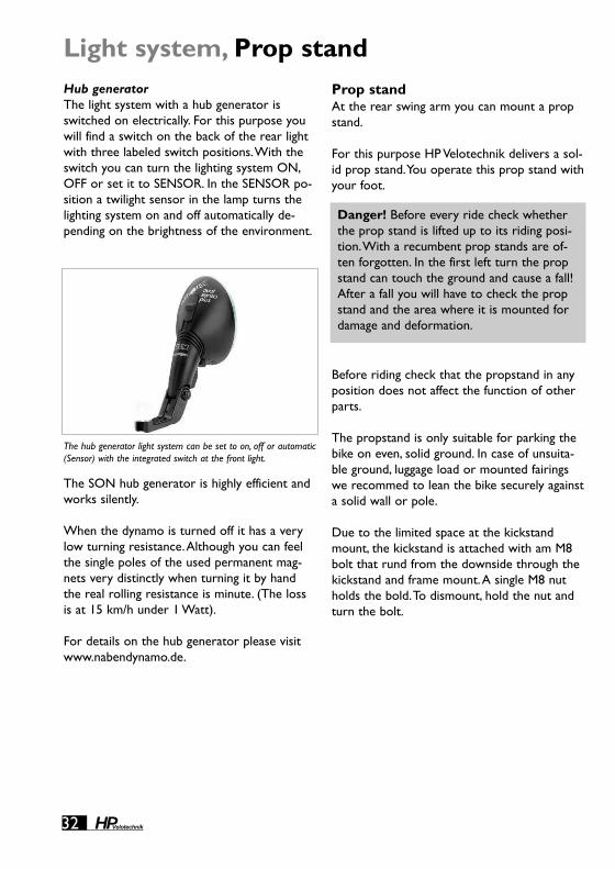
Hub generatorThe light system with a hub generator isswitched on electrically. For this purpose youwill find a switch on the back of the rear lightwith three labeled switch positions.With theswitch you can turn the lighting system ON,OFF or set it to SENSOR. In the SENSOR po-sition a twilight sensor in the lamp turns thelighting system on and off automatically de-pending on the brightness of the environment.
The SON hub generator is highly efficient andworks silently.
When the dynamo is turned off it has a verylow turning resistance.Although you can feelthe single poles of the used permanent mag-nets very distinctly when turning it by handthe real rolling resistance is minute. (The lossis at 15 km/h under 1 Watt).
For details on the hub generator please visitwww.nabendynamo.de.
Prop standAt the rear swing arm you can mount a propstand.
For this purpose HP Velotechnik delivers a sol-id prop stand.You operate this prop stand withyour foot.
Before riding check that the propstand in anyposition does not affect the function of otherparts.
The propstand is only suitable for parking thebike on even, solid ground. In case of unsuita-ble ground, luggage load or mounted fairingswe recommed to lean the bike securely againsta solid wall or pole.
Due to the limited space at the kickstandmount, the kickstand is attached with am M8bolt that rund from the downside through thekickstand and frame mount.A single M8 nutholds the bold.To dismount, hold the nut andturn the bolt.
Light system, Prop stand
The hub generator light system can be set to on, off or automatic(Sensor) with the integrated switch at the front light.
Danger! Before every ride check whetherthe prop stand is lifted up to its riding posi-tion.With a recumbent prop stands are of-ten forgotten. In the first left turn the propstand can touch the ground and cause a fall!After a fall you will have to check the propstand and the area where it is mounted fordamage and deformation.

Mai
nten
ance
and
car
e
Maintenance and careYour Speedmachine is fitted with the latest bi-cycle technology that does not require muchmaintenance.
However, you will have to maintain your bicy-cle regularly, as it is with other vehicles too.Atleast once a year the bicycle has to be takento a bicycle mechanic for an overall service.Only this way a long lasting and safe functionof all parts of your bicycle can be guaranteed.It maintains the value of your bicycle as well asthe fun and the safety while riding for manyyears.
Read in this chapter how you can carry outsmaller maintenance and care works betweenthe services.
For a quick overview of the works to be donetake a look at the warranty pass on page 58.
Wear and TearAs on many other vehicles, some parts on abicycle are affected by wear and tear.The lifeti-me expectation of these parts depends on theintensity and type of use as well as on themaintenance and care. Please keep in mind thatthe process of wear and tear is normal and noreason for a warranty claim against your dea-ler or HP VELOTECHNIK.
You will find more specific information on we-ar and tear in the chapters on the relevantparts.
Maintenance and care, Brakes
Caution! The maintenance works of this re-cumbent partly require special tools andskills. Do only work within your limits and,in the interests of your own safety, do notgo beyond. Should you be uncertain at anypoint, get in contact with your local dealer.
BrakesThe brake pads suffer from wear due to fric-tion and have to be exchanged then. Dependingon riding conditions, they can last bewteen afew hundred up to several thousand kilome-ters. Please read the manual of the brake man-ufacturer carefully.
With rim brakes the rim walls suffer from wear.When the rims are too worn the tire pressurecan tear up the rim and damage the wheelPlease have your bicycle mechanic check yourrims at the latest after the second brake padchange and exchange them if necessary.
cable operated (mechanical) brakesThe brake pads of your brakes are worn whenyou can pull the lever further and further tothe handlebar before the pads touch the rim.Rim brakes:When the pads are so worn thatyou can't see the cross grooves of the padanymore you will have your bicycle mechanicexchange the brake pads.
To balance the wear of the brake pads you cantighten the cable with the adjuster barrelwhere the cable goes into the brake lever. Firstloosen the locknut, then undo the screw so farthat the wheel turns, barely not touching thepads, hold the screw and tighten the locknutagain towards the brake lever.Take care thatthe slot of the adjuster points down so thatno moisture enters from above or the front.
Caution! Damaged cables where singlewires stick out have to be exchanged imme-diately. Otherwise your brake system mayfail - danger! Please take care that the cableends are always protected with a cap.Always keep the cables shortly trimmed.Leaving too much cable extending past thecable anchor can result in the cable catchingin the rotor or wheel, which could then bepulled in the calliper, causing the wheel tolock up.
33HPVelotechnik

34 HPVelotechnik
Brakes
hydraulic rim brakesTo balance the wear of the brake pads there isa turning knob at the brake lever.Turn thisknob anti clockwise to move the pads closerto the rim.As soon as the knob doesn't turnanymore the brake pads have to be exchanged.Before you change the pads turn the knobclockwise as far as it will go, back to the initialposition.
hydraulic disc brakesMAGURA disc brakes feature a fully automaticpad wear adjustment. Brake pads are subjectto wear, therefore regularly check the thick-ness of your brake pads and replace them, ifnecessary. The minimum thickness of thebrake pad incl. metal backing is 2.5 mm.
mechanical disc brakesIf the brake pads are worn so far that tighten-ing the cable tension is not sufficient, you canre-align the brake calliper in the slotted holesand adjust the inner brake pad with the hexbolt at the hub side of the brake calliper. Havethis adjustment work done by a qualified bikemechanic.
Check your brake pads frequently as explainedin the manual supplied by the brake manufac-turer.Worn brake pads, oily od damaged padsmust be exchanged immediately by a qualifiedbike mechanic.
Hydraulic brakesMAGURA hydraulic brakes use low viscositymineral oil that, contrary to DOT brake liquidused in cars, does not absorb water.Thus, youdon't have to change the oil. Please read theMAGURA manual that comes with the bike.Youwill find more detailed maintenance instruc-tions in the manual "Workshop" that is avail-able for download from MAGURA atwww.magura.com. In case of a damaged hoseor any leakage of oil always consult a qualifiedtechnician in a bike shop.
Caution! Never activate the lever bladewithout the brake pads in place and with thewheel dismounted.When you transport thebicycle without wheels always use the trans-port clips delivered with your bike or put apiece of cardboard in the brake calliper toreplace the disc. Carefully separate brakepads that have moved together with ascrewdriver.
Danger! All maintenance work on the hy-draulic system of your brakes may only becarried out by a qualified technician. In casethese works are carried out without the re-quired knowledge and skills the brake sys-tem might fail which can lead to a seriouscrash.
Caution! Keep the brake cable clean whereit is not protected by the cable housing. Dueto the mounting position of the brake leverwith under seat steering, moisture and dirtmay enter the cabel and cause drag and ex-cessive wear. Lube the ends of the cable toprotect against moisture.
Caution! Keep the brake lever clean. Dueto the mounting position, water and dirtcould collect inside the lever around the hy-draulic cylinder.This could lead to excessivewear or leakage of the hydraulic system.
All moving parts of the gear system are affect-ed by wear. Cleaning and lubricating theseparts frequently can prolong the life of theseparts, however they will have to be replacedonce worn out.The cables have to be checked,cleaned and serviced regularly.
Expect more wear and corrosion when thebike is often parked outside in bad weatherconditions.
Mai
nten
ance
and
car
e
35HPVelotechnik
Gear systemPlease read the manual of the gear systemmanufacturer carefully when you want to workon it.
Your dealer will have carefully adjusted yourderailleur gearing system before handing overthe bike. But during the first 300 kilometers(186 miles) of riding the gear cables canstretch, making the gear indexing imprecise.The chain then climbs only hesitantly onto thenext sprocket.
Adjust the barrel adjuster where the gear ca-ble goes into the rear derailleur. Do it in smallsteps of half a turn.
Check after each adjustment whether thechain moves cleanly up to the next largersprocket.To do this, either turn the cranks byhand or ride the bike.
When the chain climbs up easily, you need tocheck that it still goes down easily onto thesmallest sprocket. If necessary turn the barreladjuster a little more and then try shiftinggears again.
Gear system
Danger! If the chain shifts over the smallestor the biggest sprocket you have to readjustthe end-limit adjusters of the rear or thefront derailleur. Incorrect adjustment canlead to the chain coming off, getting stuck ordamaging the spokes, which may result in se-rious falls.The adjustment of the end-limitadjusters is a job for the professional cyclemechanic.
Danger! If the bike falls over, the derailleuror its mounting can be bent so that themovement of the derailleur changes. Checkthe movement and have it readjusted byyour bicycle mechanic, if necessary.
Caution! Damaged cables that show forexample single wires have to be changedimmediately. Otherwise they may damageyour gear system.Take care that the endsof the cables are protected with fittingcaps.
Caution! Take care not to bend the cableguides at the frame since they can break andcome off!

36 HPVelotechnik
ChainChainThe chain is a wearing part that has to be lu-bricated regularly and to be changed at signsof excessive wear and tear.
Lubricating the chainDiligent lubrication is important.The chain ofyour Street Machine GT is approximately 2.5times longer than a standard bicycle chain (ap-prox. 3.8 m). But it also lasts longer since achain only wears while bending at the sprok-kets and the chain rings.
Use a good chain oil that won't leave a stickyfilm on the chain.The chain oil must not con-tain any aggressive chemical substances thatmight affect the surface of the chain tubes orchain idler.
Specialist stores sell biodegradable lubricants.HP VELOTECHNIK solely recommendsPROFIDRYLUBE.This lubricant is purely based onPTFE (Teflon) that keeps the chain clean anddry.This way dirt simply falls off and the tubesalways stay clean.Your dealer can obtain itfrom HP VELOTECHNIK.
It is important that you clean the chain with acloth before lubricating. Otherwise the freshoil washes the dirt that clings to the chain intothe gaps and the bushings where the dirt cau-ses heavy wear.
Do not use any solvents to clean the chain!The solvent washes the oil off the bearingparts, stays there and dilutes the fresh oil sothat a sufficient lubrication is not guaranteed. Ifyou have treated the chain with a solvent youwill have to heat it up with a hot air torch orboil it in chain grease.
An effective protection against corrosion iscritical for a long chain life. Some minutes afteryou have oiled the chain rub it with a cloth toremove superfluous oil from the outer surface.Wax the chain thoroughly with a wax spray.The wax keeps off water, protects from corro-sion and makes dirt fall off easily.
If the chain has become wet after riding in therain you should put your bicycle in a dry andheated room, and every day you should turnthe crank and so move the chain until it is dryagain. Otherwise it is difficult for the moisturein the tubes to evaporate which may lead tocorrosion at the chain.
Danger! Take care not to pour any oil onthe rims, brake discs or the tires.The brakesystem could fail or the tires could slip awaysuddenly.The oil affects the rubber of yourtires and could damage them.While lubrica-ting cover the surrounding area with an oldnewspaper.

Mai
nten
ance
and
car
e
37HPVelotechnik
Changing the chainThe chain is one of the parts of the bike thatwill wear out.This shows in a stretching of thechain.Worn out chains do not fit the sprocketsand chain rings anymore and wear them awayvery quickly.
Check the chain regularly for lengthening. Forthis purpose try to remove the chain from thechain ring.The chain may come off to a maxi-mum of 5 mm. For a more precise reading youcan buy a chain measurement gauge in your bi-ke shop that you simply put into the chain.
Only use chains that are suitable for the gearsystem of your bike. Otherwise a precise gearshifting is not guaranteed any more. Pleaseconsult your dealer on this topic. He will alsoassist you in checking your sprockets and chainrings.A new chain does not fit a worn sprok-ket or chain ring.We recommend chains fromSRAM with smoothly rounded edges.They alsoshift gears very well.
HP VELOTECHNIK delivers spare chains by themeter via your dealer. For this purpose pleaseindicate the exact length of your chain or or-der it a little bit longer if you want to be sureit fits.You will need approx. 3,8 m of chain.
Caution! When you change the chain takecare that the new chain does not show anysharp edges or burrs.Very thin racing chainsare also not suitable since they wear thechain tubes and the chain roller much faster.
The chain length has to be fitted so that thearm of the derailleur is not fully stretchedwhen you shift onto the big chain ring in thefront and the big rear sprocket.The derailleurmust be able to compensate a tightening ofthe chain by 4 cm. Please see also the manualof the derailleur manufacturer on the choiceof the correct chain length.
See that the joining link is not bigger in sizethan the other chain links to avoid irregularchain sounds.We recommend the joining linksby SRAM (power links). Every time you changethe chain you also have to mount a new po-wer link.
Make sure that any chain links in the chain arenot stiff, as this can cause some annoying andnot obvious problems with the gear system.
Make sure that you have not wtisted the chainthrough 180 degrees before joining it back to-gether.
Caution! The chain has to be closed with aspecial joining link or a chain riveting toolthat expands the ends of the rivet while ri-veting (ROHLOFF revolver).A poorly joinedchain may break, you can come off the pe-dals and fall. If you are in doubt please haveadjustments of the chain length or the chan-ging of the chain be done by your bicyclemechanic.

38 HPVelotechnik
Chain tubesThe chain protection tubes are made of a longlasting plastic that features very low friction,slow wear and good noise damping.The tubesprotect your clothes against the chain oil aswell as the chain against dirt from the road.
The upper tubes are fastened with an ex-changeable retention spring, the lower tubesthrough two adjustable clips.
The tubes are worn by the chain and have tobe cut at the ends and expanded again (or ex-changed) after 3.000-5.000 km approximately,depending on how many kilometers have beenridden, on the chain type and the overall ridingcondition.You can extend this maintenance in-terval by turning the tubes by a quarter turnfrom time to time so that they do not keepwearing out in the same place.
The intensity of the wear depends mainly onthe chain type. Please see also the instructionson "Chain" on page 36.
In order to perform any work at the chain tu-bes you'll have to open the chain and finallyclose it again. Please see the instructions on"Chain" on page 36.
The distance of the upper chain tube to thechainwheel can be adjusted by sliding the tubein the retention spring. It must be securedwith the rubber tube over the spring.
Expanding the tube endsThe ends of the tubes are expanded like atrumpet so that the chain can enter smoothlywithout friction and without making noises.
When the ends are worn out you can renewthem through expansion. Remove the chain byopening the powerlink or open it with a spe-cial chain riveting tool. Cut the worn part ofthe tube exactly perpendicular with a sharpknife.
Heat the last 5-10 mm at the end of the tubewith a gas burner or a candle and turn it per-manently until the color of the utmost edgeturns from a dull black to a shiny black. Nowyou expand the end with a proper tool, e.g.the rounded grip of a screwdriver. Quench theexpanded end immediately with cold water.
Take care that the tubes don't catch fire.Atany rate work in a place with sufficient ventila-tion.
Chain tubes
Caution! The rear ends of the upper chaintube have to be secured against moving witha tight rubber tube over the retentionspring.Without the rubber tube the chaintube may be dragged forward into the turn-ing chain guide and thus be damaged by thechain.
Caution! Check the chain tubes frequentlyif they are damaged or defective. Replace de-fective chain tubes immediately. If the chaintubes are worn in the aerea of the retentionspring or tube mounts, the chain will touchthe retention spring, leading to breakage ofthe spring and mounts.As a result, the chaintube can get into the drive train and blockit!
Caution! Take care that the chain tubeskeep at least a 5 cm distance to the rear andfront derailleur when the chain is stretchedto the maximum, and that the tubes are wellfastened. If necessary you will have to shor-ten the tubes. If the end of a chain tube getsinto the rotating drive train it can be blok-ked and the chain tubes may be destroyed.

Mai
nten
ance
and
car
e
39HPVelotechnik
If the tube is too short after you have cut it sothat there is not enough protection anymore ithas to be replaced.You can buy spare tubes ei-ther as uncut tubes or already cut into thecorrect length, complete with retention springfrom your specialist dealer.
Changing the tubesIn order to exchange single parts in the upperchain tubes cut the old tube at the retentionspring at the chain roller and pull the remain-ing part off the spring. Now move the smoothpart of the new tube through the spring andexpand the tube end as described above.
Changing the complete upper chain pro-tection or the retention springDisassemble the chain roller. For this purposeundo the screw in the chain roller with anAllen key SW 8.
Remember the exact position of the spacers.Take the bolt off the frame together with thechain roller. Between frame and chain rollerthe frame is encased in a transparent plastictube.
Take the retention spring off this plastic tubeand put on the new retention spring.Turn thespring so that the retention springs run underthe spacer to the tubes and the wires lie be-tween frame and chain tube, that way the spi-rals look outwards.
Lubricate the shaft of the retaining bolt. Pushthe bolt through the chain roller, the washer,and the chain retention into the frame.Tightenthe nut with 14-16 Nm.
Changing the lower chain tubeOpen the two retention clips. On the bottomside of the clip there is a lid that is put over ahook.You can lift up the lid with a screwdriverand expand the clip. Change the lower chaintube and close the two clips by fastening thelids over the hooks.
You can change the position of the lower chaintube by turning the mounts in which the clipsare fastened.The ideal position depends on theposition of your front boom and your chainlength.After you have undone the screws a lit-tle bit turn the mounts so that the chain bendsthe least possible.The chain tube must nottouch the fork or the rear swing arm in allgear situations-

40 HPVelotechnik
Chain rollerThe chain roller guides the chain below theseat to the rear wheel and is an essential partof the HP VELOTECHNIK No Squat design. It en-sures that no pedaling influences get into thesuspension.
Compared to other models the chain rollerhas a big diameter and it has a higher sectionin the middle to make the chain move assmoothly as possible. Due to this higher sec-tion the chain does not lie on the roller withits sharp edged links but with the bushes inthe middle that function like small bushings. Inaddition to a very low rolling resistance it alsosupports a quiet chain movement.A chain re-tention hook between the frame and the chainroller locks the roller at the bottom and keepsthe chain on the roller when you pedal back-wards.
The chain roller wears slowly and graduallyshows a sprocket shape in the higher sectionin the middle.When this middle section isworn completely the links of the chain will runon the roller. In that case you will notice thatthe chain makes more noise while running andyou should change the roller. You can pur-chase the plastic part without the bearing orthe complete roller through your dealer.
The chain roller is not symetrically shaped; therecessed side of the chain roller has to face tothe frame, the flat side outwards.
The bearings must not be treated with a jet ofwater from a high-pressure cleaner or withsolvents since it destroys the seals and remo-ves grease in the bearings. If the bearings don'tmove smoothly anymore you'll have to replacethem.
Dismounting the chain rollerSee the notes pn changing the chain tube onpage 39.
Chain roller
Caution! If this chain retention hook ismissing the chain may fall down.When youstart pedaling then the chain roller, the seator the frame may be damaged through thechain. Please consult your local specialistdealer in case you have lost this hook.
Caution! The roller comes with two main-tenance free sealed bearings.The bearingsare exchangeable. Between the bearingsthere is a spacer that keeps the correct dis-tance. If you forget to put in the spacer afteryou have dismounted the bearings they willbe destroyed when you tighten the screwwhile remounting them.

Mai
nten
ance
and
car
e
41HPVelotechnik
Suspension forkThe dust boot is very important for the func-tionality and the lasting of your fork. Unlikemany other suspension forks the CONCEPT sus-pension system has a closed dust boot, thatmeans it also does not show any openings forventilation since the ventilation happens withinthe steerer tube into the clean air inside theframe.
Please check the correct and sealed positionof the dust boot at the top and the bottombefore each ride.At the bottom the dust bootshows a slot on the inside that has to fit thewasher above the fork crown.
Also check the condition of the dust boot. Inno case may it show any cracks or holes.
If any dust or dirt enters due to wrong assem-bly or damage the wear of the bushings andthe spline mechanism increases considerably.
Suspension forkChanging the springIf the spring stiffness does not meet yourneeds you can order another spring with a dif-ferent stiffness from your dealer and have himmount it.
You can distinguish the dismounted springs bytheir color:
medium, 18-20 N/mm: redhard, linear, 24,5 N/mm, yellow(valid for Concept-suspension from 10/2005on)
The following assembly instructions are for thebicycle mechanic:
You can exchange the springs from the bottomof the fork.
Dismount the front wheel. If a mudguard ismounted you will have to undo the screw atthe fork crown and remove the mudguard.
Clean the fork and the dust boot diligently.Then remove the safety ring inside the lowerend of the steerer tube. Please keep in mindthat there is a slight pre-load on the spring andthat it comes out quickly together with thelower spring support after you have removedthe ring.
Remove the washer, the spacer and the lowerspring support.The upper spring support andthe plastic tube that surrounds the coil springmight come out too.
Change the spring and fasten the spring sup-ports at the ends of the spring. Push the plastictube back over the spring.

42 HPVelotechnik
LubricationAfter some use it may be advantageous for theperformance to lubricate the fork after it hasbeen dismounted and after the bushings havebeen cleaned.
Only use the special Concept lube, this lubri-cant is for the use at the upper bushing andthe elastomer strip of the Linear FrictionSystem below the upper bushing.
You can buy this lubricant from your HPVelotechnik dealer
Put your bicycle on a work stand so that youcan dismount the front wheel and the frontfork.
Dismount all add-on parts from the fork (frontwheel, brakes, computer sensor etc.). Undothe clamping screw of the stem.
Unscrew and then remove the end cap fromthe outer tube. For that purpose it may benecessary to hold the fitting cap with a hexnut SW 12/13 through which you put the allenkey SW 6 to undo the screw of the end cap.You may have to hold the piston rod underthe fitting cap in place.
Suspension forkSpacers that may come with the spare springhave to be mounted below the spring.Thenput the whole package again into the steerertube.
The spacer has a hole for the screw of themudguard.Align the hole in the spacer withthe thread on the back of the fork crown andpush the spacer in the steerer tube.
The upper spring support has to click in no-ticeably on the lower end of the piston rod inthe steerer tube so that there is only a 3 mmpre-load of the spring necessary to put backthe safety ring in its position in the slot in thesteerer tube.
In order to check whether the safety ring is-correctly seated in its slot take a screwdriverand push slightly on the ring, it must not movethen.
Before taking a first test ride always checkwhether all parts have been mounted correctlyand the fork works smoothly by pushing sev-eral times on the frame of the parked bicycle.
Caution! In any case either the spring sup-port or a spacer has to be directly over thesafety ring, never the spring itself.

Mai
nten
ance
and
car
e
43HPVelotechnik
Now cautiously pull the fork down out of theouter tube.Take care that you don't turn theouter tube relative to the inner steerer tubewhile working on it, since the fork has to beremounted in exactly the same position as ithas been dismounted.Therefore mark bothtubes with a pen in order to keep the correctposition.
Clean all bushings and surfaces with a drycloth. For lubrication only use the appropriatelubricant recommended by us. Other lubri-cants or chemical cleansing agents may have anegative impact on the performance of thesynthetic bushes or the linear friction dampingsystem.
Apply the lube thinly and evenly to the surfaceof the spline guide and the entire surface ofthe steerer tube as well as the inside of thelower and the upper bushing. Finally remountall parts in reverse order.
In doing this take care that you keep the posi-tion of the steerer tube in relation to the out-er tube as described above.
The spline guide of the lower bushing mustnot be damaged while inserting in the steerertube.
The upper bushing and the spacers must notcome out at the top while inserting the steer-er tube.
Adjusting the fork play (instructions for themechanic)The linear support of the suspension fork andthe transmission of the steering forces is doneby a spline system in the steerer tube and thelower bushing as well as by the upper bushing.
With the patented adjusting system you canadjust both the smooth performance of thesystem and the range of the play through thelower adjusting nuts.
It may be necessary to adjust the bearing afterthe first break in phase, later on the adjust-ment is only necessary in exception.
The adjustment of the fork play requires spe-cial tools and skills. Please have your bicyclemechanic perform this maintenance work.Thefollowing section refers to the expert.
The adjusting nuts for the fork play are pro-tected through the frame tube, therefore youwill have to dismount the fork prior to adjust-ing it.
Dismounting the forkDismount all add-on parts (front wheel,brakes, computer sensor etc.) from the fork.Undo the clamping screw of the stem and re-move the stem together with the bearing cov-er from the top of the outer tube.
Now take a rubber mallet and carefully hit thecap to remove the outer tube by pressing itdownwards through the bearings.
Grab the dust boot at the top and remove itfrom the lock nuts at the lower end of theouter tube.

44 HPVelotechnik
After you have unmounted the fork you canalso unmount the bearings and the upperbearing-cup with a fitting soft aluminum tube.This is not necessary when you only want toadjust the fork play.
Adjusting the bushingThe lower bushing is conically shaped at theoutside. It fits in a corresponding conicallyshaped part of the outer tube.
By turning the lower nut the bearing is pushedinto the outer tube and thus squeezed togeth-er which reduces the play between the bushingand the inner steerer tube.
First undo the two adjusting nuts by undoingthe lock nut that lies above and then undoingor tightening the lower nut until the steeringmooves smoothly and has optimum play.
Please note that the bushing has possibly to bepushed out of its conically shaped fitting againwhen the adjustment is too tight.
Then you tighten the lock nuts against thelower nut and refit the dust bag in its slot be-tween the lock nuts.
Mounting the forkIn case the bearing cup has been dismountedremount it with Loctite.Take care to press itinto the frame untill it is properly seated.
If the lower bearing (metric, inner diameter 40mm) has been dismounted remount it with atool (tube, inner diameter approx. 40,5 mm,outer diameter approx. 51,5 mm) as far as itwill go on its beading.
Push the outer tube of the fork from belowthrough the steering head until the lowerbearing fits the frame.
Push the upper bearing (inner diameter 39,8mm) on the outer tube and fit it into the up-per housing. Refit the bearing cover and thestem.
It is very important that all bearings fit theirhousings completely. For this purpose dis-mount the front wheel and the brake and putthe bicycle on the ground.Put the tool above the stem on the outer tubeand press all bearings into their beadings byhitting lightly on the tool.
In order to check the correct fitting of thebearings see if the following criteria are ful-filled:
● the bearing cover has no play between thebearing and the stem, and it can only be
turned with effort● the upper edge of the bearing lies in
accordance with the upper edge of thehousing
● there are no gaps between the fitting edge of the housing to the front and the steering head
Finally make the front wheel of your bicylebounce several times heavily on the ground tocheck whether the bearings still fit tightly.Thecriteria mentioned above still have to be ful-filled after this test.
Suspension fork

Mai
nten
ance
and
car
e
45HPVelotechnik

46 HPVelotechnik
Rear suspension elementRear suspension element
Changing the steel spring /DV-22)You can buy the spring for the rear suspensionelement in different spring stiffnesses fromyour dealer.
We recommend the following spring stiffnes-ses, depending on the overall weight:
up to 80 kg (183 lbs): 450 lbs./inchup to 100 kg (230 lbs): 550 lbs./inchup to 130 kg (275 lbs): 650 lbs./inch
In addition to this, your dealer can also usesprings with other spring stiffnesses or speciallightweight springs made of titanium.
In most cases the stiffness is printed onto thespring.Take care to read the imprint carefully,since the term "B650" that sometimes occursdoes not mean 650 lbs./inch!
Spring length:DV22: 83 mm (70-90 mm)
In order to change the spring you will have toremove the rear screw and swing away the re-ar frame.
Hold the main frame of your bicycle in a workstand.
If there is a safety ring at the thread of thesuspension element push it to the front sothat you can undo the adjustment ring com-pletely and then turn it to the utmost positionat the front. Remove the slotted spring reten-tion disc at the rear end.
Undo the screws of the rear suspension ele-ment with two Allen keys and push the screwout of the suspension element eye.
Danger! If the bicycle does not stand onthe ground while undoing the screws of thesuspension element the rear swing arm maycome down uncontrolled afterwards andhurt you seriously. In addition to this the ca-bles of the gear system and the brakes mayoverexpand and you would have to replacethem. Ensure that the rear swing arm comesdown in a controlled and gentle fashion byputting up a solid string or cable tie be-tween the main frame and the rear swingarm.
Danger! When the bicycle is standing onthe ground the frame and the swing armcome up against each other. Please makesure that this happens in a controlled andgentle fashion. Put a cloth between the con-tact points. Otherwise, if they come upagainst each other uncontrolled your handsmay get caught between main frame, reararm swing and suspension element and yourbicycle may be damaged.

Mai
nten
ance
and
car
e
47HPVelotechnik
Secure the spring by tightening the adjustmentring until the spring doesn't have any play any-more. If there is a safety ring, push it back intothe slot on the thread.
Move the rear swing arm back up and connectthe rear end of the suspension element withthe rear swing arm with the bolt. Lubricate thebolt thoroughly.
Secure the screws of the suspension elementwith LOCTITE and tighten the screw with 6-8Nm.
After having exchanged the spring you have toreadjust the spring pre-load as described inthe chapter on "Adjusting your new bicycle"on page 18.
Cleaning and lubricatingDo clean the suspension element, especiallythe polished piston rod, if it is dirty. Remainingdirt and sand can damage the seals of the hy-draulic system and so shorten its life consider-ably.When you often use dirty roads you canprotect the suspension element from dirt withan elastic cover that you can buy at your localdealer.
From time to time grease the thread for thespring pre-load with a drop of acid-free oil.Thus, you can always turn the adjustment ringeasily by hand. Once a year you have to greasethe pivots of the suspension element. For thatpurpose dismount the suspension element asdescribed under "Changing the Spring" on pa-ge 45.
Remove the plastic spacers and pull the metaltube out off the bushing. Lubricate the bushingand the tubes with grease. Finally remount thesuspension element.
Hydraulic dampers are effected by wear andtear through normal use. It depends on theusage of the bike, the amount of dirt on it andthe maintenance and lubrication how long itlasts.After 3000 km the damper must receivean inspection by a trained mechanic, worn outparts or the hydraulic cartridge can be repla-ced then. Due to wear of the seals oil can leakdrom the damper or the internal oil can beco-me foamy.This may lead to some noise whenthe damper is working.This noise does not ef-fect the function of the damper. Only if thereis no obvious damping after the first 5 mm oftravel, the damper should be replaced.
Please also note the maintenance instructionsof the damper manufacturer provided withyour bike.
The bushings of the rear spring element need to be lubricatedonce a year.

Swing arm pivotSwing arm pivotThe rear swing arm pivot comes with mainte-nance free bushings.They have a self lubricatingsystem with Teflon particles.The bushings sus-tain a very high load and they show almost nowear.
In case you notice play or a creaking noise atthe rear swing arm please check the twoscrews that keep the axle in the frame.Theywill have to be secured with LOCTITE.
Tightening torques:Mushroom head screw M8x25 (without rearrack): 14-16 NmScrew M8x45: 17-19 Nm
Danger! If the screws at the axle are nottight enough this leads to play and noiseswhen the spring compresses. In extremecases the swing arm may come loose whichleads to a serious fall. If the screws are tootight the thread of the axle may tear out orthe screw may be damaged.
Caution! There has to be a big washer be-tween the main frame and the end of thebushing else the busing is not able to func-tion without play and the frame will be dam-aged.
The bushings are exchangeable. For that pur-pose you will have to dismount the rear swingarm and send it together with the axle viayour specialist dealer to HP VELOTECHNIK.Afterhaving been mounted the bushings are ma-chined to adjust them.
Undoing the axle screwsIn order to mount the rear rack or thelowrider the axle screws have to be undone.We recommend you to leave one screw inplace to prevent the axle from turning.
In case the rear swing arm is to be dismount-ed completely you can prevent the axle fromturning by inserting a thin metal rod in thehole of the axle through the drilling of therear swing arm under the axle.
You can prevent the axle from turning by inserting a thin metalrod in the hole of the axle.

Mai
nten
ance
and
car
e
49HPVelotechnik
Seat cushionThe standard seat cushion consists of a 1,4 cmthick layer of flexible EVA foam.This is a blackmaterial with closed cells that is also used inthe production of high quality camping mats. Itfeels very comfortable without appearing toosoft or spongy. It is waterproof so that you candry your seat with a sweep of your hand incase your bicycle has become wet.
For better ventilation, there is an airflow cush-ion available as accessory.
This cushion consists of several layers: a softfoam and a rigid mesh which provides for anapproximately 1 cm thick air cushion with ex-cellent circulation.These two layers arewrapped up in a cover that consists of finemesh like it is known from high qualityRucksacks.
You can wash the material at 30° centigradeand it dries very quickly. In case you want towash the seat cushion take it off the seat.Thenopen the Velcro at the back and take out thefoam cushion and the Airflow insert.
Seat cushion
Caution! The seat cushion is fastened withVelcro and you can take it off. For this pur-pose it is important not to simply grab thefoam and take it off since the Velcro couldcome off. In order to take off the seat cush-ion lift up the upper part a little bit from theseat.Then you grab the cushion on bothsides together with the end of the Velcrothat sticks out slightly and remove the cush-ion slowly. In case the Velcro comes off fas-ten it again with a good glue.
Caution! Never expose the seat cushion toextreme heat or focused sunlight.The mate-rial warms up considerably.The heat maymelt the glue of the Velcro.The seat cushioncan be damaged when the rays of the sunare bundled through a lens.Take care to nev-er leave any bubble wrap on the seat in thesun.The air bubbles in the film act like aburning glass and shrink the seat cushion.

50 HPVelotechnik
Water bottle cageYou can mount 2 water bottle cages behindthe seat with a special adaptor.This sheet met-al part replaces the standard seat support atthe middle connetion of seat and frame.Theadaptor must be mounted so that the bentside comes close to the seat.
If you don’t have a lowrider, the adaptor canbe positioned so that the water bottles are lo-cated in the middle aerea of the seat.Withamounted lowrider the adaptor must beturned so that the water bottles are locatedunder the lower seat.
The derailleur tube at the front of the framecomes with threading inserts for an additionalwater bottle cage.
Another useful alternative to water bottles aresystems with a "water bag" and a drinkinghose, e. g. from SOURCE or CAMELBAG.You cansimply strap them behind the seat, onto therear rack or into the Speedbag.
Water bottle cage

Mai
nten
ance
and
car
e
51HPVelotechnik
MudguardsAt bicycles with suspension mudguards are ex-posed to very strong vibrations through whichthey may break. Please check the stays of themudguard regularly for their position andcheck the mudguards for cracks or deforma-tions. Immediately exchange damaged mud-guards.
In order to prevent falls you have to fasten thestays of the front mudguard with a securityclip that opens under pressure.When the cliphas opened once please replace it with a newone.
After you have performed service work or re-placed mudguards check if the wheels turnfreely. Between mudguard and wheel has to bea distance of at least 7 mm.
Check whether the suspension can still fullycompress with themounted mudguards.Themudguards, stays and screws (especially at theU-brace of the suspension fork) must nottouch other parts under maximum compres-sion.
WheelsThe correct air pressure is decisive forsmooth running and a good protection againstpunctures.The maximum pressure is printedon the side of your tire. Since yourSpeedmachine is fully suspended you can al-ways go for the maximum pressure.You mightfind an indication of the minimum requiredpressure on the side of the tire as well.
Since the tubes in the tires gradually loose airyou should check the air pressure beforeevery ride.
The tubes come with Presta valves (also calledfrench valves).They are very airtight and easyto pump up. For that purpose first undo thevalve cap. Now you see a small threaded rodwith a knurled nut that comes out of thevalve. Undo the knurled nut by loosening it asfar as it goes.
To pump up the tire and check the pressureyou need a pump with a gauge,preferably asolid standing air pump. Put the knob of thepump on the valve, push it completely on thevalve and then retract it a little bit. Now youcan pump up your tire easily.
Mudguards,Wheels
Caution! You must not mount additionalparts like rear lights or reflectors to themudguards since those may break then.
Danger! If branches or other obstacles getcaught in the wheels while riding and aremoved around they may drag the mudguardsalong.The mudguard can possibly fold up be-tween frame and tire and hence block thewheel which may lead to a serious fall. If youhear any unknown noises while riding stopimmediately and remove anything that mightcling to the mudguards or the wheels.
Before pumping up the tire, you have to undo the little knurlednut on the valve.
52 HPVelotechnik
After you have pumped up the tire to themaximum pressure pull off the pump knob.Secure the valve through turning the knurlednut on the threaded rod as far as it will go to-wards the valve. Finally put on the valve capagain.
The tires will be worn out, very much varyingwith your riding and braking style. Braking topowerful, so that the wheels block, reducesthe life time expectancy of your tires dramati-cally.
The spokes of the wheels connect the rimwith the hub.At the Speedmachine they addi-tionally transmit the braking power of the discbrakes.
The wheels are fastened with a quick releaselever and therefore they are susceptible totheft. For this reason always lock the wheelsalong with the frame to a solid object whenyou park your bicycle somewhere. It is alsopossible to exchange the quick release axleswith axles that have special security locks (e.g.PITLOCK) that can only be opened with a spe-cial tool.
Cleaning and conservationThe frame of the Speedmachine has a highquality and environmentally friendly two layerpowder coating.The surfaces of the aluminumparts are either polished or anodized.
To keep the surfaces brilliant over many yearsand to protect them effectively against corro-sion the bicycle has to be cleaned from dirtand then conserved.
Dried sweat but also environmental influencessuch as air pollution, dirt on the roads and es-pecially grit affect the parts, and not only maythis cause flaws but also serious structuraldamage of the parts through corrosion.
In contrast to a widespread belief particularlythe "non-rusting" aluminum is dramatically af-fected by grit! This kind of damage may not bevisible in the beginning but it leads to a seriousdanger when the part breaks.
Wheels, Cleaning and conservation
Danger! Never pump up your tires beyondthe maximum pressure.The tire may burstwhile riding or come off the rim which mayresult in a serious fall.
Danger! Check your tires on a regular basisfor damage.You should exchange tires withworn threads or damaged sidewalls.Damaged rim tapes have to be exchangedimmediately. Damages at the tires may leadto a sudden burst of the tire and thus resultin a serious fall.
Danger! Take care that your spokes are al-ways in perfect condition and the spoke ten-sion is balanced. Do not ride with wheelsthat run untrue or wheels with loose ormissing spokes.These faults may lead to atotal failure of the wheel while braking andresult in a serious fall!
Caution! To true up the wheels you needspecial skills, please have this work done byan experienced bicycle mechanic.
Mai
nten
ance
and
car
e
53HPVelotechnik
Do clean and conserve your bicycle diligently!
The best things to clean your bicycle with arewarm water and a soft cloth. If your bicycle isvery dirty first take a wet sponge to soften thedirt and then remove it. In case of bad greaseor oil stains you should use a special cleansingagent for bicycles in addition.
While cleaning your bicycle check it for anycracks, scratches, deformations, damaged parts,loose spokes etc. If you are in doubt pleaseconsult your local bike shop.
In case of small scratches at the surface of thepowder coating of the frame or the surface ofthe seat you can simply polish them away.Youcan buy a special polishing agent for epoxyresins at a specialist dealer for boat builders.Do not use a polish for metal!
After you have cleaned the bicycle dry it andtreat the paintwork and the metal surfaceswith wax.You can purchase this wax from yourlocal bike dealer as a convenient spray.
The wax passes moisture and flows into tinygaps and pores.After some minutes the sol-vent evaporates and leaves a dull and glutinousfilm. Now polish the waxed parts of your bicy-cle with a soft cloth to make it real shiny.
Do not only wax the frame but also thespokes, hubs, screws and nuts etc.You can alsoconserve the chain with wax spray after lubri-cating it, see also the chapter on "Chain", page36.
The frame has small holes for ventilation thatprevent condensation in the frame.Thesedrilling holes must not be sealed. However,moisture may enter the frame through thedrilling holes.Therefore protect the inside ofyour frame by applying wax spray through theholes.
Protect the parts where cables or chain tubesmay scratch the frame with a layer of tape.Youcan buy extra strong transparent tape at yourdo-it-yourself-store.
Caution! Do not use any cleansing agentsthat scrub or are chemically aggesive sincethey affect the paintwork. Before using anycleansing agent please test it at a part ofyour bicycle that is not immediately visible.
Caution! Do not use any high-pressurecleaner.The strong jet of water goes throughthe seals of the bearings, blows away thelube and causes corrosion of the bearingparts and the chain. In addition to this it maydamage stickers.
Caution! Any damage of the paintwork hasto be cleaned from rust and repaired imme-diately, else the damaged part in the framegives way to corrosion that nests in the sur-rounding paintwork.This can result in dam-age of the frame.

54 HPVelotechnik
Storing the bicycleBefore storinge your bicycle over a longer pe-riod of time, e. g. over winter, please take careof the following steps:
● Clean your bicycle and protect it from corrosion as described in thechapter on "Cleaning".
● Store your bicycle in a dry and warm place.
● Avoid direct sun and storage close to the heating since it affects the rubber of your tires.
● Choose the smallest sprocket and the smallest chain ring.That way the cables are in the most relaxed position.
● The tubes of your tires loose air when standing over a longer period of time. If the bicycle then rests on flat tires the tires may be damaged.Therefore hang up your bicycle or check the air pressure regularly.
The winter months are a convenient period oftime for the annual service since then youwon't have to wait long for an appointment.Many dealers offer special prices for the win-ter check.
Screws and BoltsScrews gradually settle in and through thisthey can come loose.Therefore check thescrews and bolts regularly if they are tightenedappropriately.
In the following table you will find the pre-scribed tightening torques, they refer togreased screws!
The grease also prevents your screws fromseizing in their threads so that they won't un-screw anymore. In particular screws made ofstainless steel are susceptible to this andtherefore have always to be put in with grease.Alternatively you can use LOCTITE that you ap-ply to the screw before you put it into thethread.
Always check the screws very diligently forsigns of corrosion. Rust at the screw headsmay also lead to the screw seizing in thethread.
When the metallic and shiny coating of galva-nized screws comes off and discloses dull,grey-brown steel you have to exchange thescrew.
When you exchange screws please do onlyuse screws of the same type. Screws come indifferent strength classes. Please do only usegalvanized screws of the same type andstrength, corresponding to the Germanstrength classes 8.8 or stainless steel screwsgrade A2-70, when not given any other recom-mendation. If you are in doubt please ask yourdealer.
Storing the bike, Screws and bolts

Mai
nten
ance
and
car
e
55HPVelotechnik
Tightening torques for screwsThe values indicated are meant for a friction value µ=0,125 (greased threads and screw heads).They only refer to the in-dicated parts. Please do always follow the values given in the manuals of the parts manufacturers since the following val-ues may not be up to date due to changes in the product line!
part connection screw tightening torque
V-brake:-brake lever handlebar/grip M6 SW5 4 Nm-brake calliper calliper/frame M6 8–10 Nm
cable clamping 7–9 Nmdisc brake:-brake lever handlebar/grip clamping M6 SW5 4 Nm-brake lever compensation tank Torx T7 0,6 Nm-brake calliper calliper/frame M6 SW5 6 Nm-brake disc disk/hub M4 Torx T25 4 Nm -brake housing brake lever SW8 4 Nmdynamo dynamo/adaptor M6 SW5 6–8 Nm
adaptor/frame M5 SW4 4–6 Nmsuspension element element/frame M6 6–8 Nmrear rack at the seat tube M6 SW5 8–10 Nmrear swing arm axle/frame M8 17–19 Nmb.b. set cartridge/frame 50–60 Nmchain roller roller/frame M8 SW 6 17–19 Nmcrank crank/axle 35 Nm
chain ring screws 8–11 Nmhub cassette ring 38–42 Nmquick release wheel/frame 9–12 Nmpedal pedal/crank SW15 35–40 Nmshifter lever lever/adaptor 2,5–3 Nm
adaptor/handlebar SW6 5–6 Nmderailleur derailleur/frame SW6 8–10 Nm
cable clamping 4–6 Nmmudguard stay/frame M5 SW4 4–6 Nmseat upper seat part / seat mt M6 SW4 5–6 Nm
lower seat part / frame M6 SW4 3–4 Nmframe front boom clamping M8 SW6 14–16 Nmfront derailleur front derailleur/frame M5 SW5 5–6 Nm
cable clamping M5 SW5 4–6 NmASS-stem fork/stem M8 SW6 13–14 Nm
stem adjustment M6 SW5 8–10 Nmhandlebar/stem M6 SW5 8–10 Nm
USS stem length adjustment M6 SW5 8–10 Nmmain Axle / bearings 17–19 Nmsteering rod / mounts M6 8–10 Nm

56 HPVelotechnik
WarrantyYour authorized dealer has to fully set up andadjust your bicycle, so that safe function isguaranteed.The dealer has to make a final safe-ty check and carry out a test ride.
Your cycle dealer is obliged by law to ensure,among other things, that your bicycle is not af-fected by defects which materially diminish itsvalue of suitability for the described purpose.The exact details will vary according to thecountry. In Germany, this liability ends twoyears after purchase.
In addition to this HP VELOTECHNIK offers a 10year warranty (max. 30 000 km) on the frameof the Speedmachine against damage throughmaterial or manufacturing defects.This warran-ty applies only to the original purchaser.
Damage trough wear and tear, corrosion ordamage at the surface coating is excluded.
Damage through inappropriate use, inadequatecare and maintenance, falls, crashes, overload-ing through excess weight, incorrect assemblyor modifications to the bike is also not cov-ered.The onus rests with the purchaser.Thewarranty is void if any of the instructions inthis manual are neglected.
The warranty starts with the date of purchase(receipt of the bike dealer) of a new bicycle.The warranty is processed via the bike dealerwho ordered the bicycle from us.
In case of damage the dealer has to send thedamaged frame to us so that we can check it,if asked to do so by us.
In case of warranty we will replace or repairthe damaged part with a part of our choice ora new part equal to the old one (warranty ob-ligation).We do not cover any transport,labour or any secondary costs.
In the event of any action that falls under war-ranty the original warranty period will not beprolonged and no new warranty will be given.If HP VELOTECHNIK refuses to count a repair aswarranty case we will only carry out a repairwith costs after having talked to the customeror his representative, the respective dealer.
It is mandatory for the purchaser to fill in theenclosed warranty registration form to benefitfrom the extended warranty.This filled in formhas to be sent to HP VELOTECHNIK within 4weeks after the purchase.
The warranty is only valid when the warrantypass at the end of this manual has been filledin when you received your bike and whenevery inspection listed has been done andrecorded by your bicycle mechanic within thedescribed time schedule.
In the event of any warranty the warranty passtogether with a copy of the proof of purchasehas to be sent to HP VELOTECHNIK throughyour dealer.
This warranty does not have any influence onthe rights of the purchaser according to hisstatutory rights.
Warranty

War
rant
y Pa
ss
57HPVelotechnik
Warranty PassWith the HP VELOTECHNIK Warranty Pass youcan assure the safety and proper function ofyour bicycle for many years.
Like any other vehicle your bicycle has to bechecked for safe operation before riding.Yourbicycle has to be maintained at regular inter-vals, at least once a year you will have to takeyour bicycle to a qualified bicycle mechanic fora thorough check.
The service plan on the next page shows youour mandatory maintenance and serviceworks.
If you wish you can set an upper price limit forthe service with your bicycle mechanic. If thenecessary works exceed this limit you will beinformed in advance.
Our tip:You can avoid seasonal waiting periods inspring and summer when you have your annualinspection done in the quiet months fromOctober to January. Many bike shops thenhave special winter check offers.At any ratedo make an appointment. Clean your bicycleprior to the inspection since then many of thechecks by sight can be done quickly and at lowcost.
Please have your specialist dealer record everyinspection and service work in the WarrantyPass.This is a requirement for the validity ofour expanded warranty that exceeds the legalwarranty.
Warranty Pass
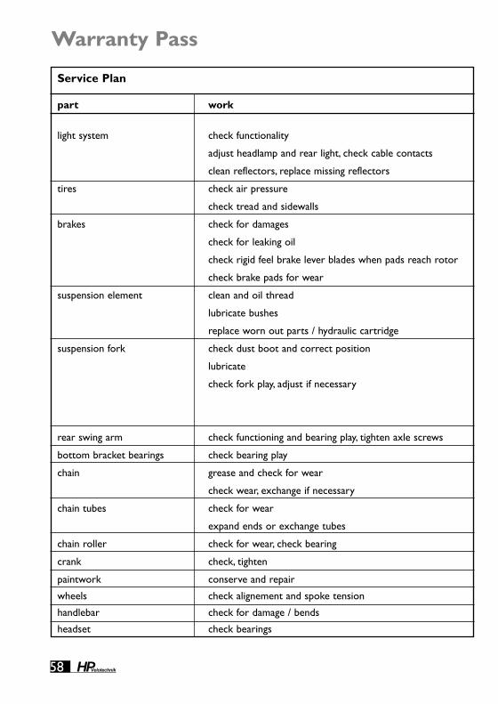
58 HPVelotechnik
Service Plan
part work
light system check functionality
adjust headlamp and rear light, check cable contacts
clean reflectors, replace missing reflectors
tires check air pressure
check tread and sidewalls
brakes check for damages
check for leaking oil
check rigid feel brake lever blades when pads reach rotor
check brake pads for wear
suspension element clean and oil thread
lubricate bushes
replace worn out parts / hydraulic cartridge
suspension fork check dust boot and correct position
lubricate
check fork play, adjust if necessary
rear swing arm check functioning and bearing play, tighten axle screws
bottom bracket bearings check bearing play
chain grease and check for wear
check wear, exchange if necessary
chain tubes check for wear
expand ends or exchange tubes
chain roller check for wear, check bearing
crank check, tighten
paintwork conserve and repair
wheels check alignement and spoke tension
handlebar check for damage / bends
headset check bearings
Warranty Pass

War
rant
y Pa
ss
59HPVelotechnik
see page before every ride monthly annually note
31 ●
●
●
51 ●
●
33 ●
●
●
●
45 ●
●
▲
41 ●
▲
● may be necessary after break-
in period, else when
required
47 ▲
▲
36 ●
▲
38 ●
▲
40 ●
▲
52 ●
51 ●
13 ▲
▲

60 HPVelotechnik
Warranty Pass
Service plan (continued)
parts work
hubs check bearing play and brake discs mount
pedal check bearing play, check binding mechanism
frame check clamping of the front boom
clean and conserve
check for damage, damage to paintwork
quick release check correct closing
derailleur check for movement and function
clean and lubricate
screws and nuts check and tighten
mudguards check for damage and correct position
valves check for correct position and air tightness
stem check clamping
check clamping screws
cables dismount, lubricate, replace if necessary
This service plan is intended to give you arough overview over the required mainte-nance and service works. In no case it can re-place the detailed instructions in this manual!
You can perform service works marked with a“●” when you have the required skills andtools as for example a torque wrench.
When you discover any defects while checkingyour bicycle they have to be repaired immedi-ately. If you are in doubt please consult yourlocal bike shop.
Works marked with a "▲" should only be car-ried out by a trained bicycle mechanic.
At the annual service the bicycle mechanic hasto carry out all works listed as well as all serv-ices and maintenance works necessary accord-ing to the momentary technical standard andprofessional knowledge.
Please follow at any rate the manuals of theparts manufacturers.
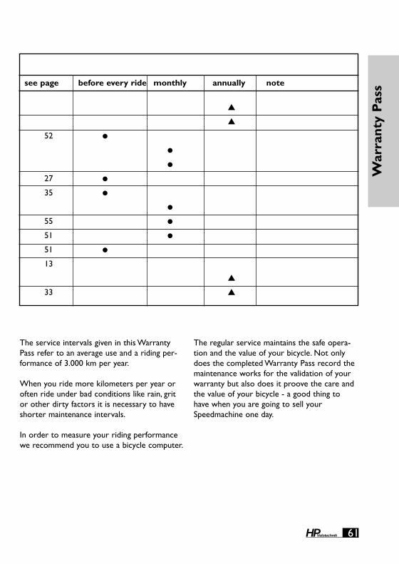
War
rant
y Pa
ss
61HPVelotechnik
see page before every ride monthly annually note
▲
▲
52 ●
●
●
27 ●
35 ●
●
55 ●
51 ●
51 ●
13
▲
33 ▲
The service intervals given in this WarrantyPass refer to an average use and a riding per-formance of 3.000 km per year.
When you ride more kilometers per year oroften ride under bad conditions like rain, gritor other dirty factors it is necessary to haveshorter maintenance intervals.
In order to measure your riding performancewe recommend you to use a bicycle computer.
The regular service maintains the safe opera-tion and the value of your bicycle. Not onlydoes the completed Warranty Pass record themaintenance works for the validation of yourwarranty but also does it proove the care andthe value of your bicycle - a good thing tohave when you are going to sell yourSpeedmachine one day.
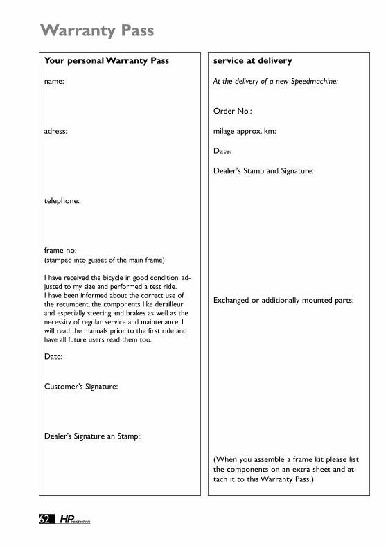
62 HPVelotechnik
Warranty Pass
service at delivery
At the delivery of a new Speedmachine:
Order No.:
milage approx. km:
Date:
Dealer's Stamp and Signature:
Exchanged or additionally mounted parts:
(When you assemble a frame kit please listthe components on an extra sheet and at-tach it to this Warranty Pass.)
Your personal Warranty Pass
name:
adress:
telephone:
frame no:(stamped into gusset of the main frame)
I have received the bicycle in good condition. ad-justed to my size and performed a test ride.I have been informed about the correct use ofthe recumbent, the components like derailleurand especially steering and brakes as well as thenecessity of regular service and maintenance. Iwill read the manuals prior to the first ride andhave all future users read them too.
Date:
Customer’s Signature:
Dealer’s Signature an Stamp::
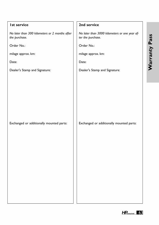
War
rant
y Pa
ss
63HPVelotechnik
2nd service
No later than 3000 kilometers or one year af-ter the purchase.
Order No.:
milage approx. km:
Date:
Dealer's Stamp and Signature:
Exchanged or additionally mounted parts:
1st service
No later than 300 kilometers or 2 months afterthe purchase.
Order No.:
milage approx. km:
Date:
Dealer's Stamp and Signature:
Exchanged or additionally mounted parts:

64 HPVelotechnik
Warranty Pass
4th service
No later than 9000 kilometers or three yearsafter the purchase.
Order No.:
milage approx. km:
Date:
Dealer's Stamp and Signature:
Exchanged or additionally mounted parts:
3rd service
No later than 6000 kilometers or two years af-ter the purchase.
Order No.:
milage approx. km:
Date:
Dealer's Stamp and Signature:
Exchanged or additionally mounted parts:

War
rant
y Pa
ss
65HPVelotechnik
6th service
No later than 15000 kilometers or five yearsafter the purchase.
Order No.:
milage approx. km:
Date:
Dealer's Stamp and Signature:
Exchanged or additionally mounted parts:
5th service
No later than 12000 kilometers or four yearsafter the purchase.
Order No.:
milage approx. km:
Date:
Dealer's Stamp and Signature:
Exchanged or additionally mounted parts:

Warranty Pass
66 HPVelotechnik
7th service
No later than 18000 kilometers or six years af-ter the purchase.
Order No.:
milage approx. km:
Date:
Dealer's Stamp and Signature:
Exchanged or additionally mounted parts:
8th service
No later than 21000 kilometers or seven yearsafter the purchase.
Order No.:
milage approx. km:
Date:
Dealer's Stamp and Signature:
Exchanged or additionally mounted parts:

67HPVelotechnik
War
rant
y Pa
ss
9th service
No later than 24000 kilometers or eight yearsafter the purchase.
Order No.:
milage approx. km:
Date:
Dealer's Stamp and Signature:
Exchanged or additionally mounted parts:
10th service
No later than 27000 kilometers or nine yearsafter the purchase.
Order No.:
milage approx. km:
Date:
Dealer's Stamp and Signature:
Exchanged or additionally mounted parts:

Warranty Pass
68 HPVelotechnik
11th service
No later than 30000 kilometers or ten yearsafter the purchase.
Order No.:
milage approx. km:
Date:
Dealer's Stamp and Signature:
Exchanged or additionally mounted parts:
12th service
No later than 33000 kilometers or eleven yearsafter the purchase.
Order No.:
milage approx. km:
Date:
Dealer's Stamp and Signature:
Exchanged or additionally mounted parts:

69HPVelotechnik
War
rant
y Pa
ss
13th service
No later than 36000 kilometers or twelve yearsafter the purchase.
Order No.:
milage approx. km:
Date:
Dealer's Stamp and Signature:
Exchanged or additionally mounted parts:
14th service
No later than 39000 kilometers or thirteenyears after the purchase.
Order No.:
milage approx. km:
Date:
Dealer's Stamp and Signature:
Exchanged or additionally mounted parts:

HP Velotechnik ● Paul J. W. Hollants und Dipl.-Ing. Daniel Pulvermüller GbRElisabethenstr. 1 ● D-65830 Kriftel ●Tel.++49 - 61 92 - 97 99 2-0 ● Fax 91 02 18 ● www.hpvelotechnik.comn i k . c o m
2008HPVelotechnik
NEWrecumbenttechnology