SPLIT TYPE ROOM AIR CONDITIONER FLOOR type INVERTER ...
68
SPLIT TYPE ROOM AIR CONDITIONER FLOOR type Models Indoor unit Outdoor unit INVERTER SERVICE INSTRUCTION R410A AGU9RLF AGU12RLF AGU15RLF AOU9RLFF AOU12RLFF AOU15RLFF
Transcript of SPLIT TYPE ROOM AIR CONDITIONER FLOOR type INVERTER ...

SPLIT TYPEROOM AIR CONDITIONER
FLOOR type
Models Indoor unit Outdoor unit
INVERTER
SERVICE INSTRUCTION
R410A
AGU9RLFAGU12RLFAGU15RLF
AOU9RLFFAOU12RLFFAOU15RLFF

CONTENTS1. DESCRIPTION OF EACH CONTROL OPERATION
1. COOLING OPERATION................................................................................................
3. DRY OPERATION.........................................................................................................2. HEATING OPERATION.................................................................................................
5. INDOOR FAN CONTROL..............................................................................................4. AUTO CHANGEOVER OPERATION............................................................................
7. LOUVER CONTROL.....................................................................................................6. OUTDOOR FAN CONTROL..........................................................................................
9. TIMER OPERATION CONTROL...................................................................................8. COMPRESSOR CONTROL..........................................................................................
11. TEST OPERATION CONTROL...................................................................................10. ELECTRONIC EXPANSION VALVE CONTROL........................................................
13. FOUR-WAY VALVE EXTENSION SELECT................................................................12. PREVENT TO RESTART FOR 3 MINUTES ( 3 MINUTES ST ).................................
15. MANUAL AUTO OPERATION ( Indoor unit body operation ).....................................14. AUTO RESTART.........................................................................................................
16. FORCED COOLING OPERATION (TEST OPERATION)............................................
18. MIN. (MINIMUM) HEAT OPERATION.........................................................................17. COMPRESSOR PREHEATING..................................................................................
19. ECONOMY OPERATION............................................................................................
22. OFF DEFROST OPERATION CONTROL...................................................................21. DEFROST OPERATION CONTROL...........................................................................
01-0101-0201-0201-0301-0401-0601-0701-0801-0901-1201-12
01-1201-1301-1301-1301-1401-1401-14
20. POWERFUL OPERATION........................................................................................... 01-1401-1501-17
23. AIR OUTLET SELECTION ( DAMPER CONTROL )................................................... 01-1824. VARIOUS PROTECTIONS.......................................................................................... 01-20
01-12
2. TROUBLE SHOOTING2-1 ERROR DISPLAY.......................................................................................................
2-1-1 INDOOR UNIT AND WIRED REMOTE CONTROLLER DISPLAY....................
3. APPENDING DATA
2-1-2 WIRED REMOTE CONTROLLER DISPLAY(OPTION)......................................2-2 TROUBLE SHOOTING WITH ERROR CODE............................................................2-3 TROUBLE SHOOTING WITH NO ERROR CODE.....................................................
02-0102-0102-02
3-1 FUNCTION SETTING.................................................................................................3-1-1 INDOOR UNIT....................................................................................................3-1-2 Procedures to change the Function Setting for wireless RC..............................
03-0103-0103-03
3-2 Thermistor Resistance Values.....................................................................................3-2-1 INDOOR UNIT....................................................................................................3-2-2 OUTDOOR UNIT................................................................................................
03-0503-0503-05
02-0302-26
2-4 SERVICE PARTS INFORMATION.............................................................................. 02-31
1 . DESCRIPTION OF EACH CONTROL OPERATION
R410A
FLOOR typeINVERTER

( Fig.1 : Outdoor temperature zone )
1. COOLING OPERATION
( Table 1 : Compressor frequency range )
01-01
( Table 2 : Limit of maximum speed based on outdoor temperature )
When the compressor operates for 30 minutes continuously at over the maximum frequency ,the maximum frequency is changed from Maximum Frequency to Maximum Frequency .
A sensor (room temperature thermistor) built in the indoor unit body will usually perceivedifference or variation between a set temperature and present room temperature, and controls the operation frequency of the compressor. * If the room temperature is 4°F(2°C) higher than a set temperature, the compressor operation frequency will attain to maximum performance.
* When the room temperature is between +4°F(+2°C) to -5°F(-2.5°C) of the setting temperature, the compressor frequency is controlled within the range shown in Table 1. However, the maximum frequency is limited in the range shown in Fig. 1 based on the fan speed mode and the outdoor temperature.
* If the room temperature is 5°F(2.5°C) lower than a set temperature, the compressor will be stopped.
Outside air Outside airtemperature temperature
97°F(36°C)
A zone 93°F(34°C) 90°F
(32°C)B zone 86°F
(30°C) 70°F(21°C)
C zone 66°F(19°C)
D zone
E zone
F zone
50°F(10°C)
32°F(0°C)
54°F(12°C)
36°F (2°C)
Minimumfrequency
Maximumfrequency
Maximumfrequency
AOU9RLFFAOU12RLFF
AOU15RLFF
10rps 76rps
12rps 91rps
57rps
56rps
Upper & LowerUpperUpper & LowerUpper
Air flow
Indoor fan modeMe Lo Quiet
A zone 76rps 45rps 37rps 29rpsB zone 76rps 45rps 37rps 29rpsC zone 76rps 45rps 37rps 26rps
AOU9/12RLFF
D zone 43rps 35rps 26rps 20rpsE zone 51rps 37rps 31rps 22rpsF zone 51rps 37rps 31rps 22rps
01-01
AOU15RLFF
A zoneB zoneC zoneD zoneE zoneF zone
Outdoortemp. zone Hi
Upper & Lowerair flow
Upper air flow
Indoor fan modeMe Lo Quiet
A zone 91rps 44rps 34rps 24rpsB zone 91rps 44rps 34rps 24rpsC zone 72rps 44rps 34rps 24rpsD zone 52rps 30rps 21rps 18rpsE zone 62rps 34rps 27rps 19rpsF zone 62rps 34rps 27rps 19rpsA zoneB zoneC zoneD zoneE zoneF zone
Outdoortemp. zone Hi
Upper & Lowerair flow
Upper air flow
76rps 45rps 37rps 29rps76rps 45rps 37rps 29rps76rps 45rps 37rps 26rps43rps 35rps 26rps 20rps51rps 37rps 31rps 22rps51rps 37rps 31rps 22rps
91rps 44rps 34rps 24rps91rps 44rps 34rps 24rps72rps 44rps 34rps 24rps52rps 30rps 21rps 18rps62rps 34rps 27rps 19rps62rps 34rps 27rps 19rps
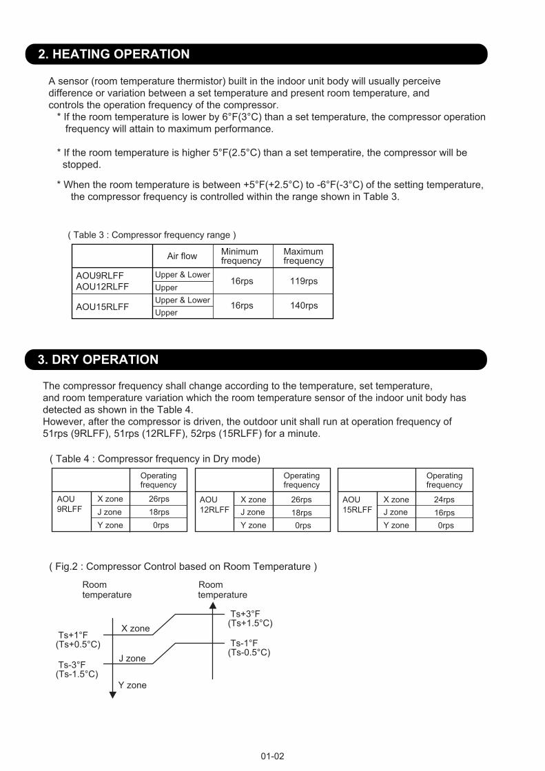
2. HEATING OPERATION
( Table 3 : Compressor frequency range )
01-02
3. DRY OPERATION
The compressor frequency shall change according to the temperature, set temperature, and room temperature variation which the room temperature sensor of the indoor unit body hasdetected as shown in the Table 4. However, after the compressor is driven, the outdoor unit shall run at operation frequency of 51rps (9RLFF), 51rps (12RLFF), 52rps (15RLFF) for a minute.
( Table 4 : Compressor frequency in Dry mode)Operatingfrequency
26rps18rps0rps
AOU9RLFF
X zoneJ zoneY zone
Operatingfrequency
J zoneY zone
X zone 26rps18rps0rps
AOU12RLFF
Operatingfrequency
J zoneY zone
X zone 24rps16rps0rps
AOU15RLFF
A sensor (room temperature thermistor) built in the indoor unit body will usually perceivedifference or variation between a set temperature and present room temperature, and controls the operation frequency of the compressor. * If the room temperature is lower by 6°F(3°C) than a set temperature, the compressor operation frequency will attain to maximum performance. * If the room temperature is higher 5°F(2.5°C) than a set temperatire, the compressor will be stopped.
* When the room temperature is between +5°F(+2.5°C) to -6°F(-3°C) of the setting temperature, the compressor frequency is controlled within the range shown in Table 3.
Ts+1°F(Ts+0.5°C) Ts-1°F
(Ts-0.5°C) Ts-3°F(Ts-1.5°C)
Ts+3°F(Ts+1.5°C)
( Fig.2 : Compressor Control based on Room Temperature )
Room Roomtemperature temperature
X zone
J zone
Y zone
Minimumfrequency
Maximumfrequency
AOU9RLFFAOU12RLFF
AOU15RLFF
16rps 119rps
16rps 140rps
Upper & LowerUpperUpper & LowerUpper
Air flow

4. AUTO CHANGEOVER OPERATION
01-03
(Fig3 : Operation flow chart)
When the air conditioner is set to the AUTO mode by remote control, operation starts in the optimummode from among the HEATING, COOLING, DRY and MONITORING modes. During operation, theoptimum mode is automatically switched in accordance with temperature changes. The temperaturecan be set between 64°F(18°C) and 88°F(30°C) in 2°F(1°C) steps.
START
Room temp.Ts+4°F(2°C)?
COOLING (AUTO:DRY) OPERATIONHEATING OPERATION
YES
YES
NO
NO
NO
TS : Setting temperature
Room temp.Ts- 4°F(2°C)?
Thermostat remainsin OFF state for 6 minutes or
longer?
System stopsor operation command other than
auto changeover operation?
NO
Thermostat remainsin OFF state for 6 minutes or
longer?
System stopsor operation command other than
auto changeover operation?
Middle zone
YES
NO
YES
Outdoor temperature 77°F(25°C)?
NO
YES
YES
NO
YES
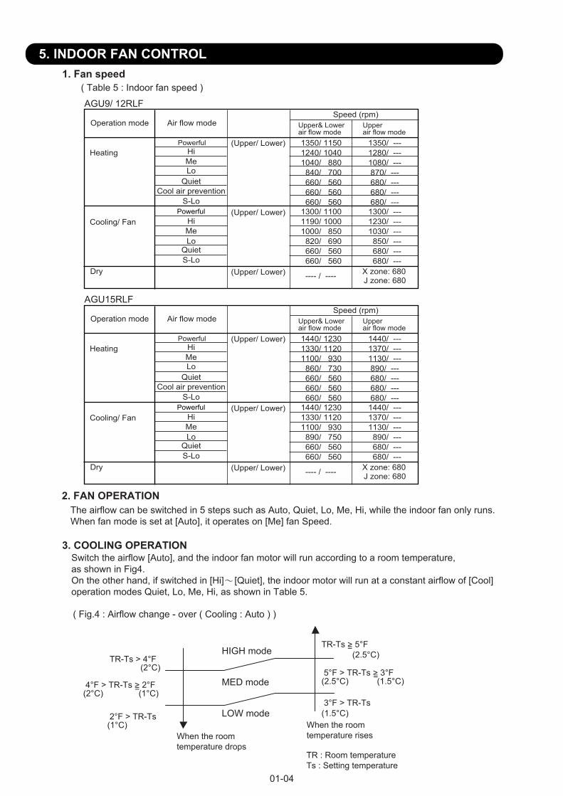
5. INDOOR FAN CONTROL
The airflow can be switched in 5 steps such as Auto, Quiet, Lo, Me, Hi, while the indoor fan only runs.When fan mode is set at [Auto], it operates on [Me] fan Speed.
01-04
2. FAN OPERATION
3. COOLING OPERATIONSwitch the airflow [Auto], and the indoor fan motor will run according to a room temperature, as shown in Fig4.On the other hand, if switched in [Hi] [Quiet], the indoor motor will run at a constant airflow of [Cool]operation modes Quiet, Lo, Me, Hi, as shown in Table 5.
( Fig.4 : Airflow change - over ( Cooling : Auto ) )
1. Fan speed( Table 5 : Indoor fan speed )
Operation mode Air flow modeSpeed (rpm)
Cooling/ Fan
Heating
Dry X zone: 680J zone: 680
Upper& Lowerair flow mode
Upperair flow mode
Hi
Hi
Me
Me
Lo
LoQuiet
Quiet
S-LoCool air prevention
(Upper/ Lower)
(Upper/ Lower)
(Upper/ Lower)
1350/ 11501240/ 10401040/ 880 840/ 700 660/ 560 660/ 560 660/ 560
1350/ ---1280/ ---1080/ --- 870/ --- 680/ --- 680/ --- 680/ ---
1300/ 11001190/ 10001000/ 850 820/ 690 660/ 560 660/ 560
1300/ ---1230/ ---1030/ --- 850/ --- 680/ --- 680/ ---
---- / ----
AGU9/ 12RLF
When the room temperature risesWhen the room
temperature dropsTR : Room temperatureTs : Setting temperature
TR-Ts > 4°F (2°C)
2°F > TR-Ts(1°C)
4°F > TR-Ts > 2°F (2°C) (1°C)=
TR-Ts > 5°F (2.5°C)
=
3°F > TR-Ts(1.5°C)
5°F > TR-Ts > 3°F(2.5°C) (1.5°C)=
HIGH mode
MED mode
LOW mode
Powerful
Powerful
S-Lo
Operation mode Air flow modeSpeed (rpm)
Cooling/ Fan
Heating
Dry X zone: 680J zone: 680
Upper& Lowerair flow mode
Upperair flow mode
Hi
Hi
Me
Me
Lo
LoQuiet
Quiet
S-LoCool air prevention
(Upper/ Lower)
(Upper/ Lower)
(Upper/ Lower)
1440/ 12301330/ 11201100/ 930 860/ 730 660/ 560 660/ 560 660/ 560
1440/ ---1370/ ---1130/ --- 890/ --- 680/ --- 680/ --- 680/ ---
1440/ 12301330/ 11201100/ 930 890/ 750 660/ 560 660/ 560
1440/ ---1370/ ---1130/ --- 890/ --- 680/ --- 680/ ---
---- / ----
AGU15RLF
Powerful
Powerful
S-Lo

The maximum value of the indoor fan speed is set as shown in Fig. 6 based on the detectedtemperature by the indoor heat-exchanger sensor on heating mode.
( Fig. 6 : Cool air prevension control )
01-05
5. HEATING OPERATIONSwitch the airflow [Auto], and the indoor fan motor will run according to a room temperature,as shown in Fig. 5 On the other hand, if switched in [Hi] [Quiet], the indoor motor will run at a constant airflow of [Heat] operation modes Quiet, Lo, Me, High, as shown in Table 5.
6. COOL AIR PREVENTION CONTROL (Heating mode)
( Fig. 5 : Airflow change - over ( Heating : Auto ) )
108°F(42°C)
86°F(30°C)
88°F(31°C)
Indoor heat exchanger temperature rises
Indoor heat exchanger temperature dropsHi
Me
LoCool air prevention
102°F(39°C)99°F
(37°C)
93°F(34°C)
84°F(29°C)75°F
(24°C)S-Lo
Switch the airflow [Auto] at cooling mode, and the indoor fan motor will run as shown in Fig. 7.7. MOISTURE RETURN PREVENTION CONTROL (Cooling mode& Dry mode)
( Fig. 7 : Indoor fan control )Compressor
ON
OFF
Indoor fanSetting air flow
Indoor fan(as shown in Table 6)
S-Lo
OFF
10 30 60 180 60 180 60 10 30(sec)
( Table 6 : Indoor fan speed )
X zone J zone
AGU9 /12RLF /15RLF 680rpm 680rpm 680rpm
DryCooling
108°F(42°C)
86°F(30°C)
Indoor heat exchanger temperature rises Indoor heat exchanger
temperature dropsPowerful
Hi
LoCool air prevention
102°F(39°C)99°F
(37°C)
S-Lo
<Normal operation> <Powerful operation>
TR-Ts > -3°F (-1.5°C)
=
-5°F > TR-Ts(-2.5°C)
-3°F > TR-Ts > -5°F(-1.5°C) (-2.5°C)
=
TR-Ts > -2°F (-1°C)
=
-4°F > TR-Ts(-2°C)
-2°F > TR-Ts > -4°F(-1°C) (-2°C)=
When the room temperature rises When the room
temperature drops
TR : Room temperatureTs : Setting temperature
Lo mode
Me mode
Hi mode
88°F(31°C)
93°F(34°C)
84°F(29°C)75°F
(24°C)
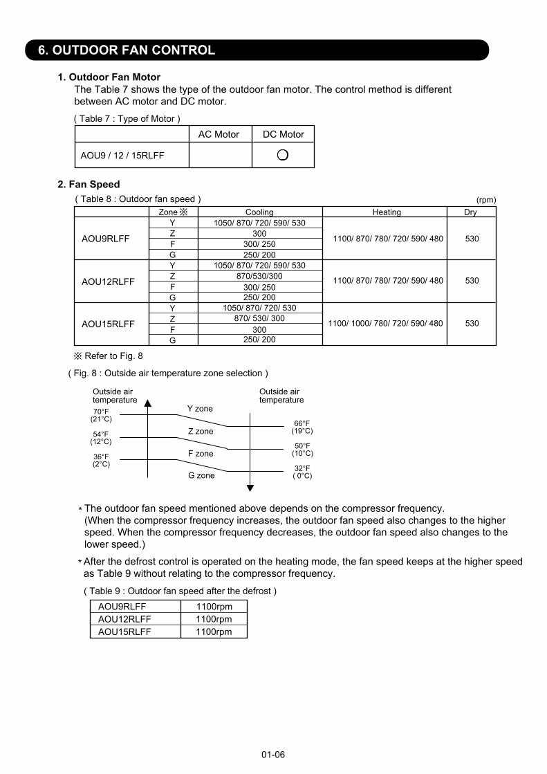
6. OUTDOOR FAN CONTROL
( Table 8 : Outdoor fan speed )
* The outdoor fan speed mentioned above depends on the compressor frequency.(When the compressor frequency increases, the outdoor fan speed also changes to the higherspeed. When the compressor frequency decreases, the outdoor fan speed also changes to thelower speed.)
* After the defrost control is operated on the heating mode, the fan speed keeps at the higher speedas Table 9 without relating to the compressor frequency.
01-06
( Table 9 : Outdoor fan speed after the defrost )
1. Outdoor Fan Motor
2. Fan Speed
AC Motor DC Motor
AOU9 / 12 / 15RLFF
The Table 7 shows the type of the outdoor fan motor. The control method is differentbetween AC motor and DC motor.
( Table 7 : Type of Motor )
AOU9RLFF 1100rpm
Cooling Heating
AOU9RLFF
AOU12RLFF
AOU15RLFF
YZ
Zone
Refer to Fig. 8
(rpm)
FGYZFGYZFG
Dry
250/ 200
300/ 250
300/ 250
1050/ 870/ 720/ 590/ 530
1050/ 870/ 720/ 530870/ 530/ 300
1050/ 870/ 720/ 590/ 530870/530/300
1100/ 870/ 780/ 720/ 590/ 480 530
1100/ 870/ 780/ 720/ 590/ 480 530
1100/ 1000/ 780/ 720/ 590/ 480 530
300
250/ 200300
250/ 200
AOU15RLFFAOU12RLFF 1100rpm
1100rpm
( Fig. 8 : Outside air temperature zone selection )
70°F(21°C)
50°F(10°C)
Outside air temperature
Outside air temperature
Z zone
Y zone
F zone
G zone
54°F(12°C)
36°F(2°C)
66°F(19°C)
32°F( 0°C)
7. LOUVER CONTROL
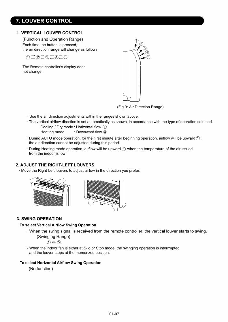
1. VERTICAL LOUVER CONTROL
Each time the button is pressed, the air direction range will change as follows:
Use the air direction adjustments within the ranges shown above.The vertical airflow direction is set automatically as shown, in accordance with the type of operation selected.
Cooling / Dry mode : Horizontal flow Heating mode : Downward flow
During AUTO mode operation, for the fi rst minute after beginning operation, airflow will be upward ; the air direction cannot be adjusted during this period.During Heating mode operation, airflow will be upward when the temperature of the air issued from the indoor is low.
(Function and Operation Range)
(Fig 9: Air Direction Range)
3. SWING OPERATION
When the swing signal is received from the remote controller, the vertical louver starts to swing.(Swinging Range)
When the indoor fan is either at S-lo or Stop mode, the swinging operation is interrruptedand the louver stops at the memorized position.
01-07
The Remote controller's display doesnot change.
Move the Right-Left louvers to adjust airfow in the direction you prefer.2. ADJUST THE RIGHT-LEFT LOUVERS
To select Vertical Airflow Swing Operation
To select Horizontal Airflow Swing Operation (No function)

8. COMPRESSOR CONTROL
01-08
1. OPEARTION FREQUENCY RANGEThe operation frequency of the compressor is different based on the operation mode asshown in the Table 10.
Cooling Heating
Minimum Maximum Minimum Maximum
AOU9/ 12RLFF 10rps 16rps 119rps76rps
AOU15RLFF 91rps 16rps12rps 140rps
Dry
Minimum Maximum
18rps 26rps
16rps 24rps
AOU9/ 12RLFF
AOU15RLFF
AOU9/ 12RLFF
AOU9/ 12RLFF
AOU9/ 12 / 15RLFF
(Table 10 : Compressor frequency range)
2. OPEARTION FREQUENCY CONTROL AT NORMAL START UPThe compressor frequency soon after the start-up is controlled as shown in the Fig.10
(Fig.10 : Compressor control at start-up)
Time Time Time Time Time(Frequency)
Frequency Frequency Frequency Frequency Frequency
FrequencyFrequencyFrequencyFrequencyFrequency
Time Time Time Time Time
(Time)
Frequency
Time 6
Frequency
Time 6
40rps 57rps 72rps 80rps 101rps 110rps
40rps 59rps 72rps 80rps 101rps 110rps
80sec 110sec 140sec 200sec 410sec350sec
3. LIMITATION OF COMPRESSOR FREQUENCY BY OUTDOOR TEMPERATUREThe minimum compressor frequency is limited by outdoor temperature as shown in the Table11.
Under Over Under Over Under Over
35rps 18rps 10rps10rps
(Table11 : Limitation of Compressor Frequency)
Under Over Under Over Under Over Under Over Under Over Under Over35rps 35rps 35rps 18rps 16rps 16rps29rps
-4°F (-20°C) 5°F (-15°C)
[ Cooling/ Dry ]
[ Heating ]
50°F (10°C) 59°F (14°C) 104°F (40°C)
AOU15RLFFUnder Over Under Over Under Over24rps 18rps 16rps12rps
32°F (0°C) 50°F (10°C) 104°F (40°C)
23°F (-5°C) 37°F (3°C) 45°F (7°C) 104°F (40°C)
AOU15RLFFUnder Over Under Over Under Over Under Over Under Over Under Over24rps 24rps 24rps 18rps 16rps 16rps24rps
-4°F (-20°C) 5°F (-15°C) 23°F (-5°C) 37°F (3°C) 45°F (7°C) 104°F (40°C)

9. TIMER OPEARTION CONTROL
1. OPEARTION FREQUENCY RANGE
The Table 12 shows the available timer setting based on the product model.
OFF timer : When the clock reaches the set time, the air conditioner will be turned off.
Operation mode
Stop mode
Set time of timer
ON timer : When the clock reaches the set time, the air conditioner will be turned on.
Operation modeStop mode
Set time of timer
The program timer allows the OFF timer and ON timer to be used in combination one time.
Operation mode
Operation will start from the timer setting (either OFF timer or ON timer) whichever is closestto the clock's current timer setting. The order of operations is indicated by the arrow in the remote control unit's display.
SLEEP timer operation cannot be combined with ON timer operation.
2. PROGRAM TIMER
Stop mode Stop mode Stop mode
Operation mode Operation mode
Set time Set time Set time Set time
01-09
9-1 WIRELESS REMOTE CONTROLLER
ON TIMER / OFF TIMER PROGRAM TIMER SLEEP TIMER
AGU9/ 12/ 15RLF
( Table 12 : Timer Setting )

3. SLEEP TIMERIf the sleep is set, the room temperature is monitored and the operation is stopped automatically.If the operation mode or the set temperature is change after the sleep timer is set, the operation iscontinued according to the changed setting of the sleep timer from that time ON.
01-10
Set temperature rises( Ts : Set temperature )
Stop of operation
Set temperature lowers( Ts : Set temperature )
Ts
Stop of operation
In the cooling operation modeWhen the sleep timer is set, the setting temperature is increased 2°F(1°C).It increases the setting temperature another 2°F(1°C) after 1 hour.After that, the setting temperature is not changed and the operation is stopped at the timeof timer setting.
Ts+2°F (1°C)+4°F (2°C)
Set 60min
In the heating operation modeWhen the sleep timer is set, the setting temperature is decreased 2°F(1°C).It decreases the setting temperature another 2°F(1°C) every 30 minutes.Upon lowering 8°F(4°C) the setting temperature is not changed and the operation stops atthe time of timer setting.
-8°F (-4°C)-6°F (-3°C)-4°F (-2°C)-2°F (-1°C)
Set 30min 30min 30min

01-11
9-2 WIRED REMOTE CONTROLLER (OPTION)The Table 13 shows the available timer setting based on the product model.
ON TIMER / OFF TIMER WEEKLY TIMER TEMPERATURE SET BACK TIMER
( Table 13 : Timer Setting )
1. ON TIMER / OFF TIMERSame to 9-1 1.ON TIMER / OFF TIMER and shown in those.
2. WEEKLY TIMERThis timer function can set operation times of the each day of the week.All days can be set together,the weekly timer can be used to repeat the timer setting for all of the days.
3. TEMPERATURE SET BACK TIMERThis timer function can change setting temperature of setting operation times of the each day of the week.This can be together with other timer setting.
Normal tmp.
ON OFF
Setting day Setting day Setting day
ON OFF ON OFF ON OFF
Set time Set time
Set back tmp.
Set time Set time
AGU9/ 12/ 15RLF

10. ELECTRONIC EXPANSION VALVE CONTROLThe most proper opening of the electronic expansion valve is calculated and controlled under the present operating condition based on the Table 14.The compressor frequency, the detected temperature by the discharge temperature sensor, the indoor heat exchanger sensor, the outdoor heat exchanger sensor, and the outdoor temperature sensor.
The expansion valve is set at 480 pulses 110seconds after the compressor had stopped.
At the time of supplying the power to the outdoor unit, the initialization of the electronicexpansion valve is operated (528 pulses are input to the closing direction).
01-12
( Table 14 : The pulse range of the electronic expansion valve control )
AOU9RLFFAOU12RLFF
AOU15RLFF
Operation mode Pulse range
Between 60 to 480 pulses.
Between 60 to 480 pulses.Cooling / Dry modeHeating mode
Cooling / Dry mode
Heating mode Between 45 to 480 pulses.
Initialization will start after 24 hours pass from the last initialization, and the compressor stops
The compressor won't enter operation status for 2 minutes and 20 seconds after the compressor is stopped, even if any operation is given.
At the time when the air conditioner is switched from the cooling mode to heating mode, thecompressor is stopped, and the four-way valve is switched in 2 minutes and 20 seconds later afterthe compressor stopped.
12. PREVENT TO RESTART FOR 3 MINUTES ( 3 MINUTES ST )
13. FOUR-WAY VALVE EXTENSION SELECT
11. TEST OPERATION CONTROL
[ Operation method ] The outdoor unit, may not operate, depending on the room temperature. In this case, keep on pressing the MANUAL AUTO button of the indoor unit for more than 10 seconds. The Operation lamp and Timer lamp will begin to flash simultaneously during cooling test run. Then, heating test run will begin in about 3 minutes when HEAT is selected by the remote control operation. (When the air conditioner is running by pressing the test run button, the Operation lamp and Timer lamp will simultaneously flash slowly.)
[ Release ]Perform the test operation for 60 minutes.Pressing the MANUAL AUTO button of the indoor unit for more than 3 seconds.
[ Using the Wired remote control (Option) ]If the Operation lamp is on, press the START/STOP button to turn it off.Press the MODE and the FAN buttons at the same time for more than two seconds to start the test operation.The operation lamp will light up and "o1" will be displayed on the set temperature display.
[ Release ]Perform the test operation for 60 minutes.Pressing the START/STOP button will stop the test operation.
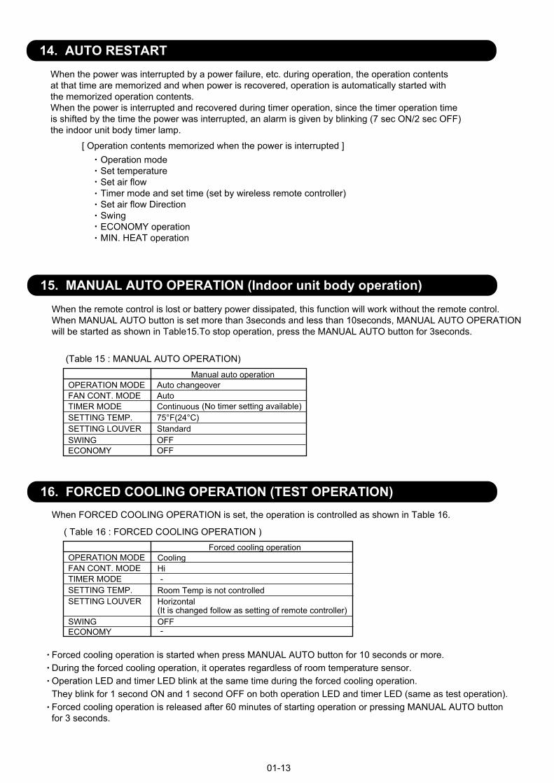
15. MANUAL AUTO OPERATION (Indoor unit body operation)When the remote control is lost or battery power dissipated, this function will work without the remote control.When MANUAL AUTO button is set more than 3seconds and less than 10seconds, MANUAL AUTO OPERATIONwill be started as shown in Table15.To stop operation, press the MANUAL AUTO button for 3seconds.
(Table 15 : MANUAL AUTO OPERATION)
01-13
16. FORCED COOLING OPERATION (TEST OPERATION)
Forced cooling operation is started when press MANUAL AUTO button for 10 seconds or more.During the forced cooling operation, it operates regardless of room temperature sensor.Operation LED and timer LED blink at the same time during the forced cooling operation. They blink for 1 second ON and 1 second OFF on both operation LED and timer LED (same as test operation).Forced cooling operation is released after 60 minutes of starting operation or pressing MANUAL AUTO button for 3 seconds.
( Table 16 : FORCED COOLING OPERATION )
When FORCED COOLING OPERATION is set, the operation is controlled as shown in Table 16.
When the power was interrupted by a power failure, etc. during operation, the operation contentsat that time are memorized and when power is recovered, operation is automatically started withthe memorized operation contents.When the power is interrupted and recovered during timer operation, since the timer operation timeis shifted by the time the power was interrupted, an alarm is given by blinking (7 sec ON/2 sec OFF)the indoor unit body timer lamp.
[ Operation contents memorized when the power is interrupted ]Operation modeSet temperatureSet air flowTimer mode and set time (set by wireless remote controller)Set air flow DirectionSwingECONOMY operationMIN. HEAT operation
14. AUTO RESTART
OPERATION MODE Auto changeoverFAN CONT. MODE AutoTIMER MODE Continuous SETTING TEMP. 75°F(24°C)SETTING LOUVER StandardSWINGECONOMY
OFFOFF
(No timer setting available)
Forced cooling operationCoolingHi
Horizontal(It is changed follow as setting of remote controller)OFF
Room Temp is not controlled
Manual auto operation
-
-
OPERATION MODEFAN CONT. MODETIMER MODESETTING TEMP.SETTING LOUVER
SWINGECONOMY
01-14
17. COMPRESSOR PREHEATING
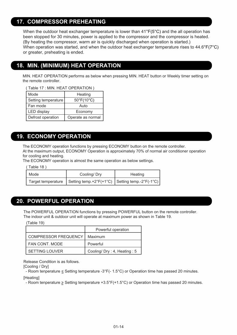
18. MIN. (MINIMUM) HEAT OPERATION
MIN. HEAT OPERATION performs as below when pressing MIN. HEAT button or Weekly timer setting on the remote controller.
Mode HeatingSetting temperature 50°F(10°C)Fan mode AutoLED display EconomyDefrost operation Operate as normal
( Table 17 : MIN. HEAT OPERATION )
19. ECONOMY OPERATIONThe ECONOMY operation functions by pressing ECONOMY button on the remote controller.At the maximum output, ECONOMY Operation is approximately 70% of normal air conditioner operation for cooling and heating.The ECONOMY operation is almost the same operation as below settings.
Mode Cooling/ Dry Heating
Target temperature Setting temp.+2°F(+1°C) Setting temp.-2°F(-1°C)
( Table 18 )
When the outdoor heat exchanger temperature is lower than 41°F(5°C) and the all operation hasbeen stopped for 30 minutes, power is applied to the compressor and the compressor is heated.(By heating the compressor, warm air is quickly discharged when operation is started.)When operation was started, and when the outdoor heat exchanger temperature rises to 44.6°F(7°C)or greater, preheating is ended.
20. POWERFUL OPERATION
The POWERFUL OPERATION functions by pressing POWERFUL button on the remote controller.The indoor unit & outdoor unit will operate at maximum power as shown in Table 19.
Release Condition is as follows.[Cooling / Dry] - Room tenperature < Setting temperature -3°F(- 1.5°C) or Operation time has passed 20 minutes.
COMPRESSOR FREQUENCY Maximum
FAN CONT. MODE Powerful
SETTING LOUVER Cooling/ Dry : 4, Heating : 5
(Table 19)
Powerful operation
=
=
[Heating] - Room tenperature > Setting temperature +3.5°F(+1.5°C) or Operation time has passed 20 minutes.

01-15
21. DEFROST OPERATION CONTROL
1. CONDITION OF STARTING THE DEFROST OPERATIONThe defrost operation starts as shown in the following Table 20.
2. CONDITION OF THE DEFROST OPERATION COMPLETION
Release Condition
Outdoor heat exchanger temperature sensor value is higher than 60.8°F(16°C) orCompressor operation time has passed 15 minutes.
(Table 20 : Condition of starting Defrost Operation)
Defrost operation is released when the conditions become as shown in Table 21.
(Table 21 : Defrost Release Condition)
If the compressor continuous operation time is less than 10 minutes, the OFF number of the compressor is counted.If any defrost operated, the compressor OFF count is cleared.
Integrating defrost
Normal defrost Compressor integrating operation time
Less than 25 minutes (9/ 12RLFF)Less than 40 minutes (15RLFF)
More than 25 minutes (9/ 12RLFF)More than 40 minutes (15RLFF)
Does not operate
Outdoor heat exchanger temp. < 1.4°F(-17°C)(at outside air temp. > 14°F(-10°C)
Outdoor heat exchanger temp. < Outside air temp.-(12.6°F (7°C))or Outdoor heat exchanger temp.< -13°F (-25°C)(at -4°F (-20°C)< Outdoor air temp.< 14°F (-10°C)
More than 240 minutes(For continuous operation)
Less than 10 minutes( For intermittent operation )
Compressor integrating operation time
Outdoor heat exchanger temperature below 26.6°F(-3°C)
More than 213 minutes(For continuous operation)
Outdoor heat exchanger temperature below 23°F(-5°C)
OFF count of the compressor40 times
=
=
=
=
=
=
Outdoor heat exchanger temp. < Outside air temp.-(12.6°F (7°C))or Outdoor heat exchanger temp. < -22°F(- 30°C) (at outside air temp. < -4°F(-20°C))
=

01-16
3. Defrost Flow ChartThe defrosting shall proceed by the integrating operation time, outdoor temperature and outdoor heat exchanger temperature as follows.
Outdoor fan : OFFCompressor speed : 0 rpsEEV : 480pulse4-way valve : OFFCompressor speed : 70rps (9RLFF) 70rps (12RLFF) 80rps (15RLFF)
(Not defrosted for 10 minutes)
Heating operation start : Compressor ON
Outdoor HEX temp.: Over 60.8°F(16°C)or
Compressor ON time: Maximum 15 minutes
Defrost end
Integrating defrost
Defrost Indicator:[Operation lamp]7 sec ON / 2 sec OFF
Defrost start
Normal defrost
=
=
=
=
==Compressor OFF count :40 times(Less than 10min.)
Compressor integrating operation:Over 240 min.
Outdoor heat exchangertemperature:Below 26.6°F(- 3°C)
Compressor integrating operation:Over 213 min.
Outdoor heat exchangertemperature:Below 23°F(- 5°C)
Intermittent operation Continuous operation
=
-4°F (-20°C)<Outside air temp.< 14°F (-10°C)
Outside air temp.< -4°F(-20°C)
Outdoor HEX temp. < 1.4°F(-17°C)
Outdoor HEX temp.< Outside air temp. -(12.6°F (7°C))or Outdoor HEX temp.< -13°F (-25°C)
Outdoor HEX temp.< Outside air temp. -(12.6°F (7°C))or Outdoor HEX temp.< -22°F(- 30°C)
Outside air temp.> -12.6°F(7°C)

22. OFF DEFROST OPEARTION CONTROL
01-17
1. OFF DEFROST OPERATION CONDITION
When operation stops in the [Heating operation] mode, if frost is adhered to the outdoor unit heatexchanger, the defrost operation will proceed automatically. In this time, if indoor unit operationlamp flashes slowly (7 sec ON / 2 sec OFF), the outdoor unit will allow the heat exchanger to defrost,and then stop.
OFF Defrost Flow Chart
Heating operation stop
Defrost start
Defrost Indicator:[Operation lamp]7 sec ON / 2 sec OFF
Outdoor heat exchanger temperature:Over 60.8°F(16°C) orCompressor ON time: Over 15 minutes
Defrost end
2. OFF DEFROST END CONDITION
Release Condition
Outdoor heat exchanger temperature sensor value is higher than 60.8°F(16°C) orCompressor operation time has passed 15 minutes.
In heating operation, the outdoor heat exchanger temperature is less than 24.8°F(- 4°C), compressor continuous operation more than 10 minutes, and compressor operation integrating time lasts for more than 30 minutes.
Outdoor heat exchanger temperature :Below 24.8°F(- 4°C)Compressor continuous operation :Over 10 minutesCompressor integrating operation :Over 30 minutes
23. AIR OUTLET SELECTION ( DAMPER CONTROL )
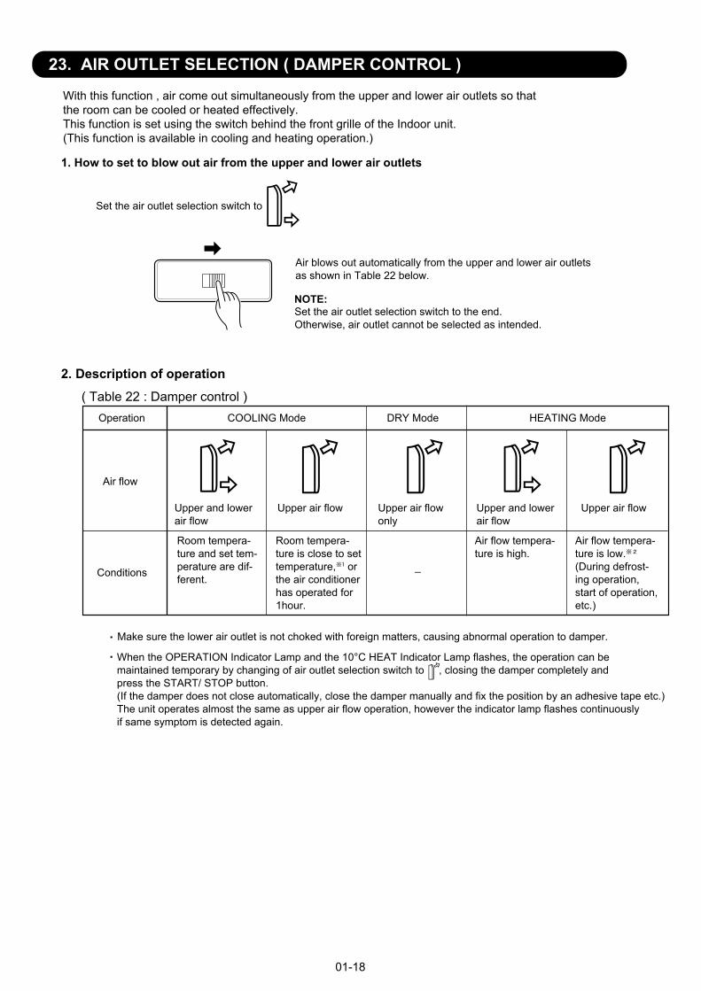
1. How to set to blow out air from the upper and lower air outlets
2. Description of operation
01-18
With this function , air come out simultaneously from the upper and lower air outlets so that the room can be cooled or heated effectively. This function is set using the switch behind the front grille of the Indoor unit. (This function is available in cooling and heating operation.)
Set the air outlet selection switch to
Air blows out automatically from the upper and lower air outlets as shown in Table 22 below.
NOTE:Set the air outlet selection switch to the end. Otherwise, air outlet cannot be selected as intended.
Operation COOLING Mode DRY Mode HEATING Mode
Air flow
Conditions
Upper and lowerair flow
Upper air flow Upper air flowonly
Upper and lowerair flow
Upper air flow
Room tempera-ture and set tem-perature are dif-ferent.
Room tempera-ture is close to settemperature, orthe air conditionerhas operated for1hour.
_
Air flow tempera-ture is high.
Air flow tempera-ture is low.(During defrost-ing operation,start of operation,etc.)
Make sure the lower air outlet is not choked with foreign matters, causing abnormal operation to damper.
When the OPERATION Indicator Lamp and the 10°C HEAT Indicator Lamp flashes, the operation can bemaintained temporary by changing of air outlet selection switch to , closing the damper completely and press the START/ STOP button.(If the damper does not close automatically, close the damper manually and fix the position by an adhesive tape etc.) The unit operates almost the same as upper air flow operation, however the indicator lamp flashes continuously if same symptom is detected again.
( Table 22 : Damper control )
22. OFF DEFROST OPEARTION CONTROL
1. OFF DEFROST OPERATION CONDITION
When operation stops in the [Heating operation] mode, if frost is adhered to the outdoor unit heatexchanger, the defrost operation will proceed automatically. In this time, if indoor unit operationlamp flashes slowly (7 sec ON / 2 sec OFF), the outdoor unit will allow the heat exchanger to defrost,and then stop.

01-19
In Heating mode
111°F(44°C)
Indoor heat exchangertemperature drops
Indoor heat exchangertemperature rises
Upper & Lowerair flow
Upper air flow95°F(35°C)
3. How to set to blow out air from the upper air outlet only
Set the air outlet selection switch to
In Cooling mode When the roomtemperature rises
When the roomtemperature drops
Upper & Lowerair flow
Upper air flow
TR-Ts > 4°F (2°C)
=
TR-Ts < 4°F (2°C)
TR-Ts >14°F (7°C)
=
TR-Ts < 14°F (7°C)
TR : Room temperatureTs : Setting temperature
2
1( Fig.11 )
( Fig.12 )
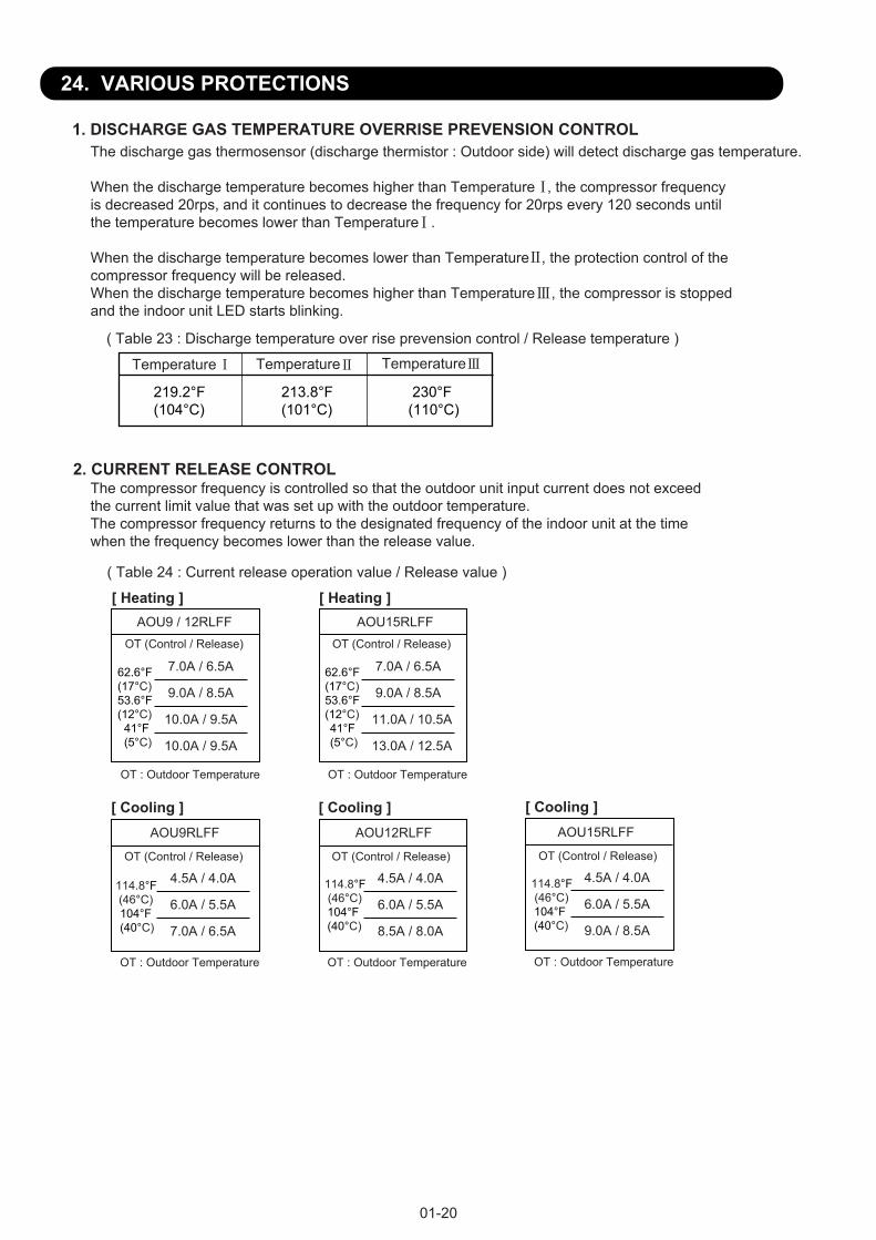
24. VARIOUS PROTECTIONS
1. DISCHARGE GAS TEMPERATURE OVERRISE PREVENSION CONTROLThe discharge gas thermosensor (discharge thermistor : Outdoor side) will detect discharge gas temperature.
When the discharge temperature becomes higher than Temperature , the compressor frequencyis decreased 20rps, and it continues to decrease the frequency for 20rps every 120 seconds until the temperature becomes lower than Temperature .
When the discharge temperature becomes lower than Temperature , the protection control of the compressor frequency will be released. When the discharge temperature becomes higher than Temperature , the compressor is stoppedand the indoor unit LED starts blinking.
219.2°F(104°C)
213.8°F(101°C)
230°F(110°C)
( Table 23 : Discharge temperature over rise prevension control / Release temperature )
Temperature Temperature Temperature
2. CURRENT RELEASE CONTROLThe compressor frequency is controlled so that the outdoor unit input current does not exceedthe current limit value that was set up with the outdoor temperature.The compressor frequency returns to the designated frequency of the indoor unit at the timewhen the frequency becomes lower than the release value.
( Table 24 : Current release operation value / Release value )
01-20
AOU9 / 12RLFF AOU15RLFF
AOU9RLFF AOU12RLFF
[ Heating ]
OT : Outdoor Temperature
[ Cooling ]
OT (Control / Release)
4.5A / 4.0A
6.0A / 5.5A
7.0A / 6.5A
114.8°F (46°C)104°F(40°C)
OT : Outdoor Temperature
OT (Control / Release)
7.0A / 6.5A
9.0A / 8.5A
10.0A / 9.5A
10.0A / 9.5A
62.6°F(17°C)53.6°F(12°C)
41°F(5°C)
[ Heating ]
OT : Outdoor Temperature
[ Cooling ]
OT (Control / Release)
4.5A / 4.0A
6.0A / 5.5A
8.5A / 8.0A
114.8°F (46°C)104°F(40°C)
OT : Outdoor Temperature
OT (Control / Release)
7.0A / 6.5A
9.0A / 8.5A
11.0A / 10.5A
13.0A / 12.5A
62.6°F(17°C)53.6°F(12°C)41°F(5°C)
AOU15RLFF
OT : Outdoor Temperature
[ Cooling ]
OT (Control / Release)
4.5A / 4.0A
6.0A / 5.5A
9.0A / 8.5A
114.8°F (46°C)104°F(40°C)
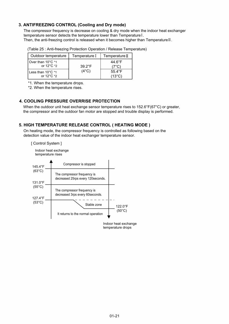
3. ANTIFREEZING CONTROL (Cooling and Dry mode)The compressor frequency is decrease on cooling & dry mode when the indoor heat exchangertemperature sensor detects the temperature lower than Temperature .Then, the anti-freezing control is released when it becomes higher than Temperature .
(Table 25 : Anti-freezing Protection Operation / Release Temperature)
4. COOLING PRESSURE OVERRISE PROTECTIONWhen the outdoor unit heat exchange sensor temperature rises to 152.6°F(67°C) or greater, the compressor and the outdoor fan motor are stopped and trouble display is performed.
5. HIGH TEMPERATURE RELEASE CONTROL ( HEATING MODE )
01-21
Outdoor temperatureOver than 10°C *1 or 12°C *2Less than 10°C *1 or 12°C *2
*1. When the temperature drops.*2. When the temperature rises.
39.2°F (4°C)
44.6°F (7°C)55.4°F(13°C)
Temperature Temperature
On heating mode, the compressor frequency is controlled as following based on thedetection value of the indoor heat exchanger temperature sensor.
[ Control System ]
Indoor heat exchange temperature rises
Indoor heat exchange temperature drops
It returns to the normal operation
Compressor is stopped
127.4°F (53°C)
131.0°F (55°C)
145.4°F (63°C)
122.0°F (50°C)
The compressor frequency is decreased 3rps every 60seconds.
The compressor frequency is decreased 25rps every 120seconds.
Stable zone

2 . TROUBLE SHOOTING
R410A
FLOOR typeINVERTER
2. TROUBLESHOOTING
02-01
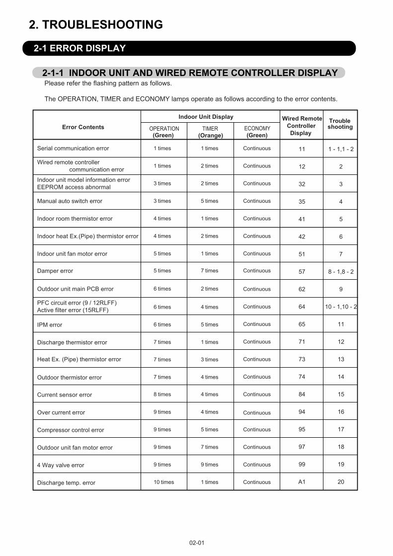
2-1 ERROR DISPLAY
2-1-1 INDOOR UNIT AND WIRED REMOTE CONTROLLER DISPLAYPlease refer the flashing pattern as follows.
The OPERATION, TIMER and ECONOMY lamps operate as follows according to the error contents.
Manual auto switch error
Indoor room thermistor error
Indoor unit model information errorEEPROM access abnormal
Wired remote controller communication error
Error Contents
Continuous
Continuous
4 times
Continuous2 times
3 times
3 times
5 times
Continuous2 times1 times
Continuous1 times1 times
Troubleshooting
(Green) (Orange)(Green)
1 times
Serial communication error
Indoor unit fan motor error
Indoor heat Ex.(Pipe) thermistor error
Continuous4 times 2 times
Continuous1 times5 times
Damper error Continuous7 times5 times
Outdoor unit main PCB error 2 times6 times
Continuous
Continuous
4 times
7 times
6 times
1 times Continuous
7 times 3 times Continuous
7 times 4 times Continuous
PFC circuit error (9 / 12RLFF)Active filter error (15RLFF)
Discharge thermistor error
Heat Ex. (Pipe) thermistor error
Outdoor thermistor error
1 - 1,1 - 2
2
3
4
5
6
7
8 - 1,8 - 2
9
10 - 1,10 - 2
11
12
13
14
15
16
17
18
19
20
Continuous8 times 4 timesCurrent sensor error
Continuous
Continuous
Continuous
5 times
9 times
9 times
7 times
Compressor control error
Outdoor unit fan motor error
Continuous
4 times9 times
Continuous
9 times 9 times4 Way valve error
1 times10 timesDischarge temp. error
Over current error
Continuous
5 times6 timesIPM error
Indoor Unit Display Wired Remote Controller Display
11
12
32
35
41
42
51
57
62
64
65
71
73
74
84
94
95
97
99
A1
OPERATION TIMER ECONOMY

02-02
When " Er " in Temperature Display is displayed, inspection of the air conditioning system is necessary. Please consult authorized service personnel.
2-1-2 WIRED REMOTE CONTROLLER DISPLAY (OPTION)
1. SELF - DIAGNOSIS
SU MOTU WETH FR SA
Unit number (usually 0)Error code
ex. Self-diagnosis check
2. ERROR CODE HISTORY DISPLAYUp to 16 memorized error codes may be displayed for the indoor unit connected to the remote controller.
1. Stop the air conditioner operation.
2. Press the SET TEMPERATURE buttons , simultaneously for 3 seconds or more to start the self-diagnosis.
4. Press the SET TEMPERATURE buttons , simultaneously for 3 seconds or more or there is no key input for 60 seconds to stop the display.
3. Press the SET TEMPERATURE button to select the error history number.
SU MOTU WETH FR SA
Error codeError history number
0 1 2 3 4 5 6 7F E d c b A 9 8
��
Lower Raise
02-03
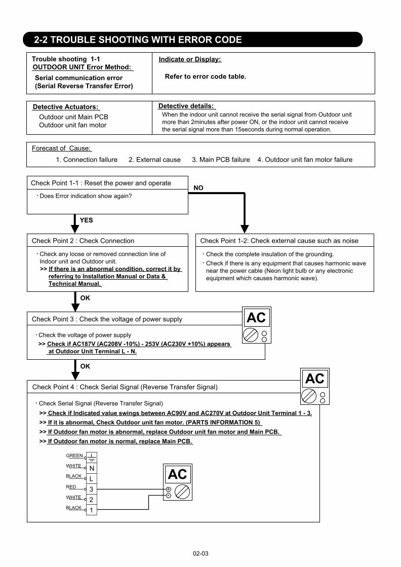
2-2 TROUBLE SHOOTING WITH ERROR CODE
Trouble shooting 1-1OUTDOOR UNIT Error Method:
Detective Actuators: Detective details:
Forecast of Cause:
OK
YESYES
NO
RED
WHITE
BLACK
BLACK
WHITE
GREEN
+-
OK
Serial communication error(Serial Reverse Transfer Error)
Outdoor unit Main PCBOutdoor unit fan motor
1. Connection failure 2. External cause 3. Main PCB failure 4. Outdoor unit fan motor failure
Check Point 1-1 : Reset the power and operate
Does Error indication show again?
Check Point 1-2: Check external cause such as noise
Check the complete insulation of the grounding.Check if there is any equipment that causes harmonic wave near the power cable (Neon light bulb or any electronic equipment which causes harmonic wave).
Check Point 2 : Check Connection
Check any loose or removed connection line of Indoor unit and Outdoor unit.>> If there is an abnormal condition, correct it by referring to Installation Manual or Data & Technical Manual.
Check Point 3 : Check the voltage of power supply
Check the voltage of power supply>> Check if AC187V (AC208V -10%) - 253V (AC230V +10%) appears at Outdoor Unit Terminal L - N.
Check Point 4 : Check Serial Signal (Reverse Transfer Signal)
Check Serial Signal (Reverse Transfer Signal)>> Check if Indicated value swings between AC90V and AC270V at Outdoor Unit Terminal 1 - 3.>> If it is abnormal, Check Outdoor unit fan motor. (PARTS INFORMATION 5)>> If Outdoor fan motor is abnormal, replace Outdoor unit fan motor and Main PCB.>> If Outdoor fan motor is normal, replace Main PCB.
When the indoor unit cannot receive the serial signal from Outdoor unit more than 2minutes after power ON, or the indoor unit cannot receivethe serial signal more than 15seconds during normal operation.
NL321
Indicate or Display:
Refer to error code table.

02-04
Trouble shooting 1-2INDOOR UNIT Error Method:
Detective Actuators: Detective details:
Forecast of Cause:
OK
YESYES
NO
+-
OK
Serial communication error(Serial Forward Transfer Error)
Indoor unit Controller PCBIndoor unit Fan motor
1. Connection failure 2. External cause 3. Controller PCB failure 4. Indoor unit fan motor failure
Check Point 1-1 : Reset the power and operate
Does Error indication show again?
Check Point 1-2: Check external cause such as noise
Check the complete insulation of the grounding.Check if there is any equipment that causes harmonic wave near the power cable (Neon light bulb or any electronic equipment which causes harmonic wave).
Check Point 2 : Check Connection
Check any loose or removed connection line of Indoor unit and Outdoor unit.>> If there is an abnormal condition, correct it by referring to Installation Manual or Data & Technical Manual.
Check Point 3 : Check the voltage of power supply
Check the voltage of power supply>> Check if AC187V (AC208V -10%) - 253V (AC230V +10%) appears at Outdoor Unit Terminal L - N
Check Point 4 : Check Serial Signal (Reverse Transfer Signal)
Check Serial Signal (Forward Transfer Signal)>> Check if Indicated value swings between AC30V and AC130V at Outdoor Unit Terminal 2 - 3.>> If it is abnormal, replace Controller PCB.>> If it is abnormal, Check Indoor unit fan motor. (PARTS INFORMATION 4)>> If Indoor unit fan motor is abnormal, replace Indoor unit fan motor and Controller PCB.
When the outdoor unit cannot receive the serial signal from Indoor unit more than 10seconds.
RED
WHITE
BLACK
BLACK
WHITE
GREEN
NL321
Indicate or Display:
Refer to error code table.

Trouble shooting 2INDOOR UNIT Error Method:
Detective Actuators: Detective details:
Forecast of Cause:
Check Point 2 : Check Remote Control and Controller PCB
Check Point 1 : Check the connection of terminal
OKOK
Wired remote controller communication error
Indoor unit Controller PCBWired remote control
1. Terminal connection abnormal 2. Wired remote control failure 3. Controller PCB failure
After turning off the power, check & correct the followings.Check the connection of terminal between remote control and Indoor unit,and check if there is a disconnection of the cable.
Upon correcting the removed connector or mis-wiring, reset the power.
Check Voltage at CN6 (terminal 1-3) of Controller PCB. (Power supply to Remote Control)
>> If it is DC13V, Remote Control is failure. (Controller PCB is normal) >> Replace Remote Control>> If it is DC 0V, Controller PCB is failure. (Check Remote Control once again) >> Replace Controller PCB
When the indoor unit cannot receive the signal from Wired Remote Controlmore than 1minute during normal operation.
02-05
Indicate or Display:
Refer to error code table.

Detective Actuators: Detective details:
Forecast of Cause:
Check Point 3 : Replace Controller PCB
Check Point 2 : Check Indoor unit electric components
YESYES
NO
Trouble shooting 3INDOOR UNIT Error Method:Indoor unit model information errorEEPROM access abnormal
Indoor unit Controller PCB
1. External cause 2. Defective connection of electric components 3. Controller PCB failure
Check Point 1-1 : Reset Power Supply and operate
Does Error indication show again?
Check Point 1-2 : Check external cause such as noise
Check if the ground connection is proper.Check if there is any equipment that causes harmonic wavenear the power cable (Neon light bulb or any electronicequipment which causes harmonic wave).
Note : EEPROM
EEPROM(Electronically Erasable andProgrammable Read Only Memory) is a non-volatile memory which keeps memorizedinformation even if power is turned off. It canchange the contents electronically. To change the contents, it uses higher voltage than normal, and it can not change a partial contents. (Rewriting shall be done upon erasing the all contents.) There is a limit in a number of rewriting.
Change Controller PCB.
Check all connectors.(loose connector or incorrect wiring)Check any shortage or corrosion on PCB.
When power is on and there is some below case. 1. When model information of EEPROM is incorrect. 2. When the access to EEPROM failed.
02-06
Indicate or Display:
Refer to error code table.

02-07
Trouble shooting 4
INDOOR UNITINDOOR UNIT Error Method:
Detective Actuators: Detective details:
Forecast of Cause :
OKOK
Manual auto switch error
Indoor unit Controller PCBIndicator PCBManual auto switch
When the Manual Auto Switch becomes ON for consecutive 60 ormore seconds.
1. Manual auto switch failure 2.Controller PCB and Indicator PCB failure
Check Point 1 : Check the Manual auto switch
Check if Manual auto switch is kept pressed.
Check Point 2 : Replace Controller PCB
If Check Point 1 do not improve the symptom, change Controller PCB and Indicator PCB.
Check ON/OFF switching operation by using a meter.>>If Manual Auto Switch is disabled (on/off switching), replace it.
Indicate or Display:
Refer to error code table.

Trouble shooting 5INDOOR UNITINDOOR UNIT Error Method:
Detective Actuators: Detective details:
Forecast of Cause :
Check Point 1 : Check connection of Connector
Indoor room thermistor error
Indoor unit Controller PCBRoom temperature thermistor
When Room Temperature Thermistor open or short-circuit is detected.
1. Connector connection failure 2.Thermistor failure 3. Controller PCB failure
Check if connector is removed.Check erroneous connection.Check if thermistor cable is open.>>Upon correcting the removed connector or mis-wiring, reset the power.
02-08
Indicate or Display:
Refer to error code table.
Check Point 2 : Check Point 2 : Check the voltage value between the terminals at Thermistor
OK
Thermistor Characteristics (Approx. value)
If the voltage does not appear, replace Controller PCB.
THERMISTOR(PIPE)
GRAY CN312
12
GRAY
THERMISTOR(ROOM TEMP.)
CN112BLACK
BLACK
Check Voltage at CN1 (terminal 1-2) of Controller PCB.
2.502.783.063.343.613.854.074.27Voltage value (V)
Voltage value (V)
Temperature
1.731.97
Temperature
77°F 68°F59°F50°F41°F32°F23°F14°F
104°F
1.52
113°F95°F
2.23
86°F

Trouble shooting 6INDOOR UNITINDOOR UNIT Error Method:
Detective Actuators: Detective details:
Forecast of Cause :
Check Point 2 :
62.9103.3134.2176.0233.2312.3Resistance Value (k )
Temperature (°F)
OKOK
OK
17.125.639.6Resistance Value (k )
Temperature (°F)
Indoor heat Ex.(Pipe) thermistor error
Indoor unit Controller PCBHeat Ex. temperature thermistor
When Heat Ex. Temperature Thermistor open or short-circuit is detected.
1. Connector connection failure 2.Thermistor failure 3. Controller PCB failure
Check Point 1 : Check connection of Connector
Check if connector is removed.Check erroneous connection.Check if thermistor cable is open.>>Upon correcting the removed connector or mis-wiring, reset the power.
Check Point 2 : Remove connector and check Thermistor resistance value
Thermistor Characteristics (Approx. value)
If Thermistor is either open or shorted, replace it and reset the power.
Check Point 3 : Check voltage of Controller PCB (DC5.0V)
Make sure circuit diagram of indoor unit and check terminal voltage at Thermistor (DC5.0V)
If the voltage does not appear, replace Controller PCB.
02-09
68°F50°F41°F32°F23°F14°F
122°F
11.6
140°F
10.4
144°F104°F86°F
Indicate or Display:
Refer to error code table.
THERMISTOR(PIPE)
GRAY CN312
12
GRAY
THERMISTOR(ROOM TEMP.)
CN112BLACK
BLACK

Trouble shooting 7INDOOR UNIT Error Method:
Detective Actuators: Detective details:
Forecast of Cause:
Check Point 1 : Check rotation of Fan
Check Point 2 : Check ambient temp. around motor
OK
OK
OK
Indoor unit fan motor error
Indoor unit Controller PCBIndoor unit Fan motor
1. Fan rotation failure 2. Fan motor winding open 3. Motor protection by surrounding temperature rise4. Control PCB failure 5. Indoor unit fan motor failure
Rotate the fan by hand when operation is off.(Check if fan is caught, dropped off or locked motor)>>If Fan or Bearing is abnormal, replace it.
Check excessively high temperature around the motor.(If there is any surrounding equipment that causes heat)>>Upon the temperature coming down, restart operation.
When the condition that actual frequency of Indoor Fan is below 1/3 of target frequency is continued more than 56 seconds.
02-10
Check Point 4 : Replace Controller PCB
If Check Point 1- 3 do not improve the symptom, replace Controller PCB.
Check Point 3 : Check Indoor unit fan motor
Check Indoor unit fan motor. (PARTS INFORMATION 4)>>If Indoor unit fan motor is abnormal, replace Indoor unit fan motor.
Indicate or Display:
Refer to error code table.

Detective Actuators: Detective details:
Forecast of Cause :
Indoor unit Controller PCBLimit switchDamper
When limit switch were not able to detect the close though the damper close.(Upper air flow)When limit switch were not able to detect the open though the damper open.(Upper & Lower air flow)
1. Limit switch failure 2. Shorted connector/ wire 3. Damper faulure 4. Controller PCB failure
Check Point 2 : Check Point 2 : Check Connector (CN18) / Wire
Check Point 1 : Check Limit switch
Check Point 4 : Replace Controller PCB
OKOK
OKOK
Check operation of limit switch. (any blocking by dust, etc.)Remove Limit switch and check ON/OFF switching operation by using a meter.
>>If Limit switch is detective, replace it.
Check loose contact of CN18 /shorted wire (pinched wire).>>Replace Limit switch if the wire is abnormal
Check Point 2 : Check Point 3 : Check Damper
OKOK
>>Replace Damper if the damper is abnormal
If Check Point 1 3 do not improve the symptom, change Controller PCB.
Check the obstruction of damper movement.Check the damper movement.
Trouble shooting 8-1INDOOR UNIT Error Method:Damper error(Damper(Open/Close) detection Limit switch error)
02-11
Indicate or Display:
Refer to error code table.

Detective Actuators: Detective details:
Forecast of Cause :
Indoor unit Controller PCBLimit switch
When the limit switch detects open and close at the simultaneous.
1. Limit switch failure 2. Shorted connector/ wire 3. Controller PCB failure
Check Point 2 : Check Point 2 : Check Connector (CN18) / Wire
Check Point 1 : Check Limit switch
Check Point 3 : Replace Controller PCB
OKOK
Check operation of limit switch. (any blocking by dust, etc.)Remove Limit switch and check ON/OFF switching operation by using a meter.
>>If Limit switch is detective, replace it.
Check loose contact of CN18 /shorted wire (pinched wire).>>Replace Limit switch if the wire is abnormal
OKOK
If Check Point 1 & 2 do not improve the symptom, change Controller PCB.
Trouble shooting 8-2INDOOR UNIT Error Method:Damper error(Damper(Open/Close) simultaneous detection Limit switch error)
02-12
Indicate or Display:
Refer to error code table.
Detective Actuators: Detective details:
Forecast of Cause:
Check Point 2 : Replace Main PCB
YESYES
NO
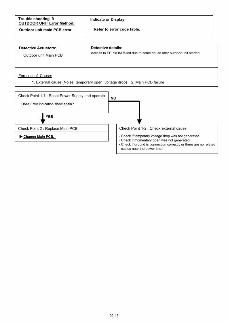
Trouble shooting 9OUTDOOR UNIT Error Method:Outdoor unit main PCB error
Outdoor unit Main PCB
1. External cause (Noise, temporary open, voltage drop) 2. Main PCB failure
Check Point 1-1 : Reset Power Supply and operate
Does Error indication show again?
Check Point 1-2 : Check external cause
Check if temporary voltage drop was not generated.Check if momentary open was not generated.Check if ground is connection correctly or there are no relatedcables near the power line.
Change Main PCB.
Access to EEPROM failed due to some cause after outdoor unit started.
02-13
Indicate or Display:
Refer to error code table.
Trouble shooting 10-1INDOOR UNITOUTDOOR UNIT Error Method:
Detective Actuators: Detective details:
Forecast of Cause :
OKOK
OKOK
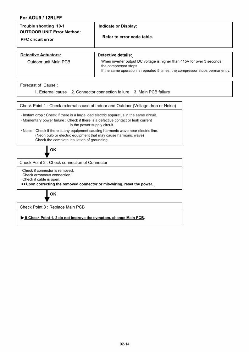
PFC circuit error
Outdoor unit Main PCB
1. External cause 2. Connector connection failure 3. Main PCB failure
Check Point 2 : Check connection of Connector
Check if connector is removed.Check erroneous connection.Check if cable is open.>>Upon correcting the removed connector or mis-wiring, reset the power.
Check Point 3 : Replace Main PCB
If Check Point 1, 2 do not improve the symptom, change Main PCB.
Check Point 1 : Check external cause at Indoor and Outdoor (Voltage drop or Noise)
Instant drop : Check if there is a large load electric apparatus in the same circuit.Momentary power failure : Check if there is a defective contact or leak current in the power supply circuit.Noise : Check if there is any equipment causing harmonic wave near electric line. (Neon bulb or electric equipment that may cause harmonic wave) Check the complete insulation of grounding.
02-14
When inverter output DC voltage is higher than 415V for over 3 seconds, the compressor stops.If the same operation is repeated 5 times, the compressor stops permanently.
Indicate or Display:
Refer to error code table.
For AOU9 / 12RLFF
Trouble shooting 10-2INDOOR UNITOUTDOOR UNIT Error Method:
Indicate or Display:
Detective Actuators: Detective details:
Forecast of Cause :
OKOK
OKOK
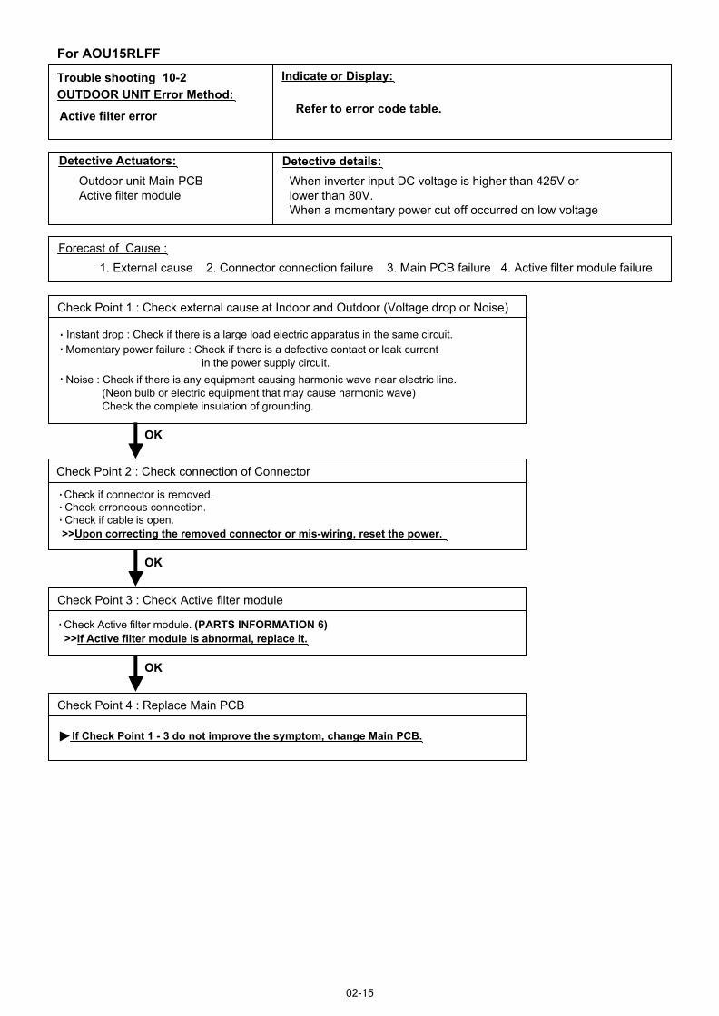
Active filter error
Outdoor unit Main PCBActive filter module
1. External cause 2. Connector connection failure 3. Main PCB failure 4. Active filter module failure
Check Point 2 : Check connection of Connector
Check if connector is removed.Check erroneous connection.Check if cable is open.>>Upon correcting the removed connector or mis-wiring, reset the power.
Check Point 4 : Replace Main PCB
If Check Point 1 - 3 do not improve the symptom, change Main PCB.
Check Point 1 : Check external cause at Indoor and Outdoor (Voltage drop or Noise)
Instant drop : Check if there is a large load electric apparatus in the same circuit.Momentary power failure : Check if there is a defective contact or leak current in the power supply circuit.Noise : Check if there is any equipment causing harmonic wave near electric line. (Neon bulb or electric equipment that may cause harmonic wave) Check the complete insulation of grounding.
02-15
OKOK
Check Point 3 : Check Active filter module
For AOU15RLFF
Check Active filter module. (PARTS INFORMATION 6)>>If Active filter module is abnormal, replace it.
When inverter input DC voltage is higher than 425V orlower than 80V.When a momentary power cut off occurred on low voltage
Refer to error code table.

Trouble shooting 11OUTDOOR UNIT Error Method:
Detective Actuators: Detective details:
Forecast of Cause :
Check Point 3 : Check Outdoor Fan
OK
OK
Check Point 6 : Replace Main PCB
OKOK
OKOK
Check Point 1 : Check connections of Outdoor Unit Electrical Components
IPM error
Outdoor unit Main PCBOutdoor unit Transistor PCB (15L)Compressor
1. Defective connection of electric components 2. Outdoor Fan Operation failure 3. Outdoor Heat Exchanger clogged 4. Compressor failure 5. Main PCB failure 6. Transistor PCB failure (For AOU15RLFF)
Check if connector is removed.Check if the terminal connection is loose.
Check erroneous connection.Check if cable is open.>>Upon correcting the removed connector or mis-wiring, reset the power.
Check Point 2 : Check Outdoor Fan, Heat Exchanger
Is there anything obstructing the air distribution circuit?Is there any clogging of Outdoor Heat Exchanger?Is the Fan rotating by hand when operation is off ?>> If the Fan Motor is locked, replace it.
Check Outdoor Fan Motor. (Refer to Trouble shooting 18) >> If the Fan Motor is failure, replace it.
Check Point 4 : Check Compressor
(PARTS INFORMATION 2)Check Compressor.
If Check Point 1 5 do not improve the symptom, change Main PCB.
When more than normal operating current to IPM in Main PCB flows,the compressor stops.After the compressor restarts, if the same operation is repeated within 40sec,the compressor stops again.If and repeats 5 times, the compressor stops permanently.
02-16
OKOK
Check Point 5 : Check Transistor PCB (For AOU15RLFF)
(PARTS INFORMATION 7)Check Transistor PCB.
Indicate or Display:
Refer to error code table.

Trouble shooting 12INDOOR UNITOUTDOOR UNIT Error Method:
Detective Actuators: Detective details:
Forecast of Cause :
Check Point 2 :
Check Point 3 :
62.5100.9129.8168.6221.1292.9Resistance Value (k )
Temperature (°F)
OKOK
OKOK
40.0
2.03.44.66.38.7Resistance Value (k )
Temperature (°F)
Discharge thermistor error
Outdoor unit Main PCBDischarge pipe temperature thermistor
When Discharge pipe temperature thermistor open or short-circuit is detected at power ON or while running the compressor.
1. Connector connection failure 2.Thermistor failure 3. Main PCB failure
Check Point 1 : Check connection of Connector
Check if connector is removed.Check erroneous connection.Check if thermistor cable is open.>>Upon correcting the removed connector or mis-wiring, reset the power.
Check Point 2 : Remove connector and check Thermistor resistance value
Thermistor Characteristics (Approx. value)
If Thermistor is either open or shorted, replace it and reset the power.
Check Point 3 : Check voltage of Main PCB (DC5.0V)
Make sure circuit diagram of outdoor unit and check terminal voltage at Thermistor (DC5.0V)
If the voltage does not appear, replace Main PCB.
02-17
194°F176°F158°F
26.3
104°F
17.8
122°F
12.3
140°F
86°F
212°F
2.6
230°F
41°F32°F23°F14°F 68°F50°F
248°F
Indicate or Display:
Refer to error code table.
THERMISTOR(PIPE)
THERMISTOR(DISCHARGE)
THERMISTOR(OUTDOOR)
BLACKBLACK
BROWN or BLACK
BLACK
BLACK
1234
1234
123
123
CN61
CN62
AOU15RLFF
THERMISTOR(PIPE)
THERMISTOR(DISCHARGE)
THERMISTOR(OUTDOOR)
BLACKBLACK
BROWNBROWN
BLACK
BLACK
1234
1234
123
123
CN71
CN70
AOU9 / 12RLFF
BROWN or BLACK
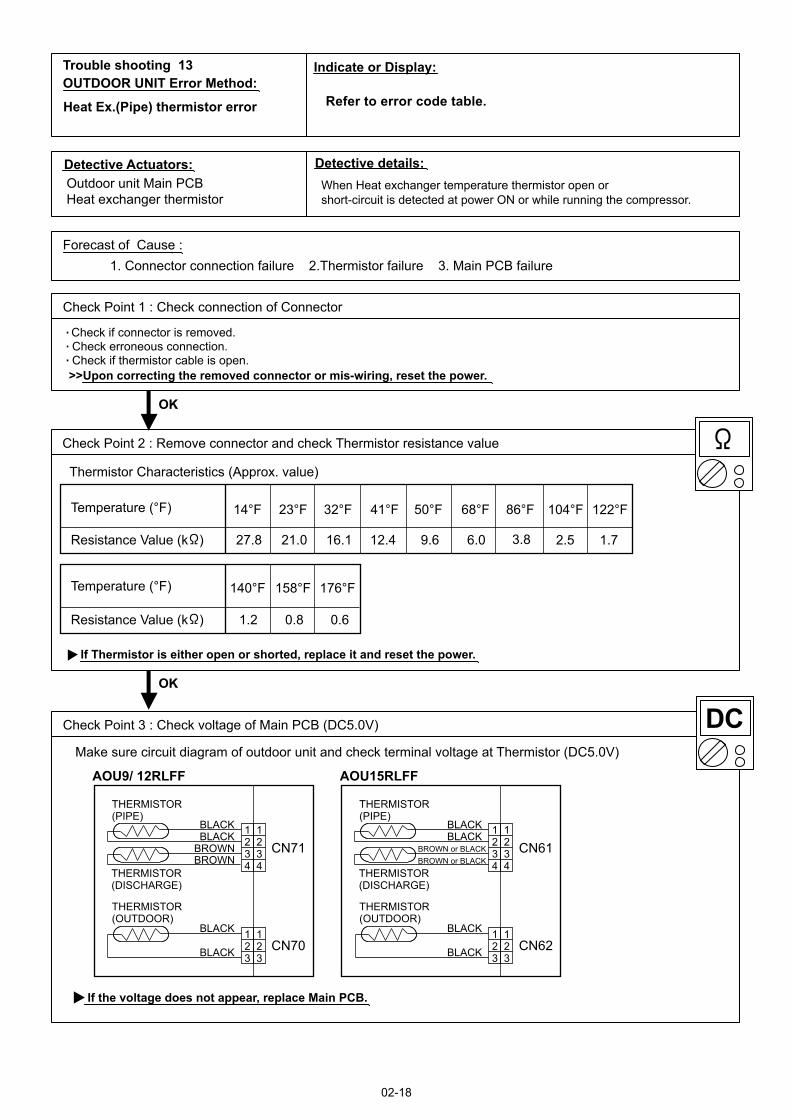
Trouble shooting 13OUTDOOR UNIT Error Method:
Detective Actuators: Detective details:
Forecast of Cause :
Check Point 2 :
6.09.612.416.121.027.8Resistance Value (k )
Temperature (°F)
OKOK
OKOK
3.8
0.60.81.2
1.72.5
Resistance Value (k )
Temperature (°F)
Heat Ex.(Pipe) thermistor error
Outdoor unit Main PCBHeat exchanger thermistor
When Heat exchanger temperature thermistor open or short-circuit is detected at power ON or while running the compressor.
1. Connector connection failure 2.Thermistor failure 3. Main PCB failure
Check Point 1 : Check connection of Connector
Check if connector is removed.Check erroneous connection.Check if thermistor cable is open.>>Upon correcting the removed connector or mis-wiring, reset the power.
Check Point 2 : Remove connector and check Thermistor resistance value
Thermistor Characteristics (Approx. value)
If Thermistor is either open or shorted, replace it and reset the power.
02-18
23°F14°F
176°F158°F140°F
86°F68°F50°F41°F32°F 122°F104°F
Indicate or Display:
Refer to error code table.
Check Point 3 : Check Point 3 : Check voltage of Main PCB (DC5.0V)
Make sure circuit diagram of outdoor unit and check terminal voltage at Thermistor (DC5.0V)
If the voltage does not appear, replace Main PCB.
THERMISTOR(PIPE)
THERMISTOR(DISCHARGE)
THERMISTOR(OUTDOOR)
BLACKBLACK
BLACK
BLACK
1234
1234
123
123
CN61
CN62
AOU15RLFF
THERMISTOR(PIPE)
THERMISTOR(DISCHARGE)
THERMISTOR(OUTDOOR)
BLACKBLACK
BROWNBROWN
BLACK
BLACK
1234
1234
123
123
CN71
CN70
AOU9/ 12RLFF
BROWN or BLACKBROWN or BLACK

Trouble shooting 14OUTDOOR UNIT Error Method:
Detective Actuators: Detective details:
Forecast of Cause :
Check Point 2 :
26.935.246.662.384.2115.2Resistance Value (k )
Temperature (°F)
OKOK
OKOK
20.7
6.4
8.012.6
Resistance Value (k )
Temperature (°F)
Outdoor thermistor error
Outdoor unit Main PCBOutdoor thermistor
When Outdoor temperature thermistor open or short-circuit is detected at power ON or while running the compressor.
1. Connector connection failure 2.Thermistor failure 3. Main PCB failure
Check Point 1 : Check connection of Connector
Check if connector is removed.Check erroneous connection.Check if thermistor cable is open.>>Upon correcting the removed connector or mis-wiring, reset the power.
Check Point 2 : Remove connector and check Thermistor resistance value
Thermistor Characteristics (Approx. value)
If Thermistor is either open or shorted, replace it and reset the power.
02-19
5°F-4°F
95°F
5.2
104°F
4.2
113°F
3.5
122°F
2.8
131°F
86°F50°F41°F32°F23°F14°F 68°F
Indicate or Display:
Refer to error code table.
Check Point 3 : Check Point 3 : Check voltage of Main PCB (DC5.0V)
Make sure circuit diagram of outdoor unit and check terminal voltage at Thermistor (DC5.0V)
If the voltage does not appear, replace Main PCB.
THERMISTOR(PIPE)
THERMISTOR(DISCHARGE)
THERMISTOR(OUTDOOR)
BLACKBLACK
BLACK
BLACK
1234
1234
123
123
CN61
CN62
AOU15RLFF
THERMISTOR(PIPE)
THERMISTOR(DISCHARGE)
THERMISTOR(OUTDOOR)
BLACKBLACK
BROWNBROWN
BLACK
BLACK
1234
1234
123
123
CN71
CN70
AOU9/ 12RLFF
BROWN or BLACKBROWN or BLACK

Trouble shooting 15OUTDOOR UNIT Error Method:
Detective Actuators: Detective details:
Forecast of Cause :
Check Point 4 : Replace Main PCB
YES
NO
OK
Current sensor error
Outdoor unit Main PCB
Check Point 2 : Check connections of Outdoor Unit Electrical Components
Check if connector is removed.Check if the terminal connection is loose.
Check erroneous connection.Check if cable is open.>>Upon correcting the removed connector or mis-wiring, reset the power.
Check Point 1-2 : Check external cause at Indoor and Outdoor (Voltage drop or Noise)
1. Defective connection of electric components 2. External cause 3. Main PCB failure
Instant drop : Check if there is a large load electric apparatus in the same circuit.Momentary power failure : Check if there is a defective contact or leak current in the power supply circuit.Noise : Check if there is any equipment causing harmonic wave near electric line.(Neon bulb or electric equipment that may cause harmonic wave) Check the complete insulation of grounding.
Check Point 1-1 : Reset Power Supply and operate
Does Error indication show again?
When Input Current Sensor has detected 0A, while Inverter Compressor is operating at higher than 56rps, after 1minute upon starting the Compressor. (Except during the defrost operation)
02-20
If Check Point 1, 2 do not improve the symptom, change Main PCB.
Indicate or Display:
Refer to error code table.

Trouble shooting 16OUTDOOR UNIT Error Method:
Detective Actuators: Detective details:
Forecast of Cause :
OKOK
Check Point 2: Replace Main PCB
Outdoor unit Main PCBCompressor
Trip detection
If Check Point 1 do not improve the symptom, change Main PCB.
02-21
OKOK
Check Point 3: Replace Compressor
If Check Point 2 do not improve the symptom, change Compressor.
1. Outdoor unit fan operation defective, foreign matter on hear exchanger, excessive rise of ambient temperature2. Main PCB failure3. Compressor failure (lock, winding short)
"Protection stop by overcurrent generation after inverter compressor start processing completed'' generated consecutively 10 times. * The number of generations is reset if the start-up of the compressor succeeds.
No obstructions in air passages?Heat exchange fins cloggedOutdoor unit fan motor checkAmbient temperature not raised by the effect of other heat sources?Discharged air not sucked in?
Check Point 1 : Check the outdoor unit fan operation, heat exchanger, ambient temperature
Indicate or Display:
Refer to error code table.
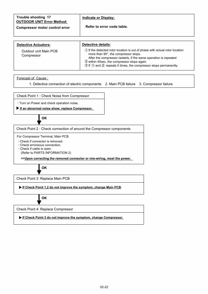
Trouble shooting 17OUTDOOR UNIT Error Method:
Detective Actuators: Detective details:
Forecast of Cause :
Check Point 2 : Check connection of around the Compressor components
OKOK
OKOK
Check Point 3: Replace Main PCB
Outdoor unit Main PCBCompressor
Compressor motor control error
1. Defective connection of electric components 2. Main PCB failure 3. Compressor failure
If Check Point 1,2 do not improve the symptom, change Main PCB.
Check if connector is removed.Check erroneous connection.Check if cable is open.
>>Upon correcting the removed connector or mis-wiring, reset the power.
(Refer to PARTS INFORMATION 2)
For Compressor Terminal, Main PCB
If the detected rotor location is out of phase with actual rotor location more than 90°, the compressor stops.After the compressor restarts, if the same operation is repeated within 40sec, the compressor stops again.If and repeats 5 times, the compressor stops permanently.
02-22
Check Point 1 : Check Noise from Compressor
Turn on Power and check operation noise.
If an abnormal noise show, replace Compressor.
OKOK
Check Point 4: Replace Compressor
If Check Point 3 do not improve the symptom, change Compressor.
Indicate or Display:
Refer to error code table.

Trouble shooting 18OUTDOOR UNIT Error Method:
Detective Actuators: Detective details:
Forecast of Cause:
Check Point 3 : Check Outdoor unit fan motor
OK
OK
Outdoor unit fan motor error
Outdoor unit Main PCBOutdoor unit Fan motor
1. Fan rotation failure 2. Motor protection by surrounding temperature rise 3. Main PCB failure4. Outdoor unit fan motor
Check Point 1 : Check rotation of Fan
Rotate the fan by hand when operation is off.(Check if fan is caught, dropped off or locked motor)>>If Fan or Bearing is abnormal, replace it.
Check Outdoor unit fan motor. (PARTS INFORMATION 5)>>If Outdoor unit fan motor is abnormal, replace Outdoor unit fan motor.
Check Point 4 : Check Output Voltage of Main PCB
Check outdoor unit circuit diagram and the voltage. (Measure at Main PCB side connector)
If the voltage is not correct, replace Main PCB.
When outdoor fan rotation speed is less than 100rpm in 20 seconds after fan motor starts, fan motor stops.After fan motor restarts, if the same operation within 60sec is repeated 3 times in a row, compressor and fan motor stops.If and repeats 5 times in a row, compressor and fan motor stops permanently.
Read wire DC voltage
Red - Black(Vm)
240 - 400V (9/12/15RLFF)
White - Black(Vcc) 15 1.5V
02-23
CN800[9/12/15RLFF]
1234567
BLACKWHITEYELLOW
RED
FM
FAN MOTOR
Check Point 2 : Check ambient temp. around motor
OK
Check excessively high temperature around the motor.(If there is any surrounding equipment that causes heat)>>Upon the temperature coming down, restart operation.
Indicate or Display:
Refer to error code table.
BROWN

Trouble shooting 19OUTDOOR UNIT Error Method:
Detective Actuators: Detective details:
Forecast of Cause :
OKOK
OKOK
4-way valve error
Indoor unit Controller PCBHeat Ex. temperature thermistorRoom temperature thermistor4-way valveMain PCB
When the indoor heat exchanger temperature is compared withthe room temperature, and either following condition is detected continuously two times, the compressor stops.
1. Connector connection failure 2. Thermistor failure 3. Coil failure 4. 4-way valve failure5. Main PCB failure 6. Controller PCB failure
Check Point 1 : Check connection of Connector
Check if connector is removed.Check erroneous connection.Check if thermistor cable is open.>> Upon correcting the removed connector or mis-wiring, reset the power.
Check Point 3 : Check the solenoid coil and 4-way valve
Remove CN30 (For 9/12RLFF) and CN500 (For 15RLFF) from PCB and check the resistance value of coil.Resistance value is 1.88k 2.29k at 68°F (20°C).>> If it is Open or abnormal resistance value, replace Solenoid Coil.
02-24
Cooling or Dry operation[Indoor heat exchanger temp.] - [Room temp.] > 20°F(10°C)Heating operation[Indoor heat exchanger temp.] - [room temp.] < - 20°F(-10°C)
If the same operation is repeated 5 times, the compressor stops permanently.
[ Solenoid coil ]
Check each piping temperature, and the location of the valve by the temperature difference.>> If the value location is not proper, replace 4-way valve.
[ 4-way valve ]
OKOK
Check Point 5 : Replace Controller PCB
If Check Point 1- 4 do not improve the symptom, replace Controller PCB.
Check Point 2 : Check each thermistor
Isn’t it fallen off the holder?Is there a cable pinched?
>> Check characteristics of thermistor (Refer to Trouble shooting 5, 6), If defective, replace the thermistor
Indicate or Display:
Refer to error code table.
Check Point 4 : Check the voltage of 4-way valve
Check the voltage CN30 (For 9/12RLFF) or CN500 (For 15RLFF) of Main PCB.Check if AC187V(AC208V-10%) - 253V(AC230V+10%) appears at CN 30 or CN500 of Main PCB.[ Heating operation ] >> If it is not voltage, Replace Main PCB.[ Cooling operation ] >> If it is voltage, Replace Main PCB.
OKOK

Trouble shooting 20INDOOR UNITOUTDOOR UNIT Error Method:Discharge temperature error
02-25
Indicate or Display:
Refer to error code table.
<Cooling operation>
OK
OK
OK
OK
OK
<Heating operation>
Outdoor unit Main PCBDischarge temperature thermistor
"Protection stop by "discharge temperature 230°F(110°C) during compressor operation"" generated 2 times within 24 hours.
Check Point 1 : Check if 3-way valve(gas side) is open.
Discharger thermistor characteristics check.(Check by disconnecting thermistor from PCB.)
* For the characteristics of the thermistor, refer to the "Trouble shooting 12".
Check Point 4 : Check the discharge thermistor
EEV open?Strainer clogging check (before and after EEV, ACM oil return)
Check Point 3 : Check the outdoor unit fan,heat exchanger
Check for foreign object at heat exchangerCheck if fan can be rotated by hand.Motor check (PARTS INFORMATION 5)
Check Point 2 : Check the EEV, strainer
Check Point 5 : Check the refrigerant amount
Leak check
EEV open?Strainer clogging check (before and after EEV, ACM oil return)
Check Point 2 : Check the EEV, strainer
If the 3-way valve(gas side) was closed, open the 3-way valve(gas side) and check operation.
Check Point 1 : Check if 3-way valve(liquid side) is open.
If the 3-way valve(liquid side) was closed, open the 3-way valve(liquid side) and check operation.
OK
Detective Actuators: Detective details:
Forecast of Cause :
Refer to "Service Parts Information 3". Refer to "Service Parts Information 3".
1. 3-way valve not opened 2. EEV defective, strainer clogged3. Outdoor unit operation failure, foreign matter on heat exchanger4. Discharge temperature thermistor failure 5. Insufficient refrigerant6. Main PCB failure
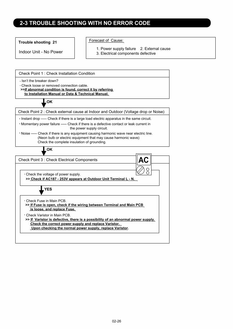
Trouble shooting 21 Forecast of Cause:
OKOK
Indoor Unit - No Power 1. Power supply failure 2. External cause 3. Electrical components defective
Check Point 1 : Check Installation Condition
Isn’t the breaker down?Check loose or removed connection cable.>>If abnormal condition is found, correct it by referring to Installation Manual or Data & Technical Manual.
Check Point 2 : Check external cause at Indoor and Outdoor (Voltage drop or Noise)
Instant drop ----- Check if there is a large load electric apparatus in the same circuit.Momentary power failure ----- Check if there is a defective contact or leak current in the power supply circuit.Noise ----- Check if there is any equipment causing harmonic wave near electric line. (Neon bulb or electric equipment that may cause harmonic wave) Check the complete insulation of grounding.
02-26
2-3 TROUBLE SHOOTING WITH NO ERROR CODE
Check Point 3 : Check Electrical Components
YESYES
Check the voltage of power supply.>> Check if AC187 - 253V appears at Outdoor Unit Terminal L - N.
Check Fuse in Main PCB.>> If Fuse is open, check if the wiring between Terminal and Main PCB is loose, and replace Fuse.Check Varistor in Main PCB.>> If Varistor is defective, there is a possibility of an abnormal power supply. Check the correct power supply and replace Varistor. Upon checking the normal power supply, replace Varistor.
OK

Trouble shooting 22 Forecast of Cause:
Check Point 3 : Check Electrical Components
OKOK
OKOK
YESYES
OK
Check Point 1 : Check Installation Condition
Outdoor Unit - No Power 1. Power supply failure 2. External cause 3. Electrical Components defective
Isn’t the breaker down?Check loose or removed connection cable.>>If abnormal condition is found, correct it by referring to Installation Manual or Data & Technical Manual.
Check Point 2 : Check external cause at Indoor and Outdoor (Voltage drop or Noise)
Instant drop ----- Check if there is a large load electric apparatus in the same circuit.Momentary power failure ----- Check if there is a defective contact or leak current in the power supply circuit.Noise ----- Check if there is any equipment causing harmonic wave near electric line. (Neon bulb or electric equipment that may cause harmonic wave) Check the complete insulation of grounding.
Check the voltage of power supply.>> Check if AC187 - 253V appears at Outdoor Unit Terminal L - N.
Check Fuse in Main PCB.>> If Fuse is open, check if the wiring between Terminal and Main PCB is loose, and replace Fuse.Check Varistor in Main PCB.>> If Varistor is defective, there is a possibility of an abnormal power supply. Check the correct power supply and replace Varistor. Upon checking the normal power supply, replace Varistor.
If the symptom does not change by above Check 3, replace Main PCB.
02-27

Trouble shooting 23 Forecast of Cause:
Check Point 2 : Check external cause at Indoor and Outdoor (Voltage drop or Noise)
Check Point 1 : Check indoor and outdoor installation condition
Check Point 3 : Check Electrical Components at Indoor and Outdoor
OK
OK
OKOK
No Operation (Power is ON)1. Setting/ Connection failure 2. External cause 3. Electrical component defective
Indoor Unit - Check incorrect wiring between Indoor Unit - Remote Control.Or, check if there is an open cable connection.Are these Indoor Unit, Outdoor Unit, and Remote Control suitable model numbers to connect?
>> If there is some abnormal condition, correct it by referring to Installation manual and Data & Technical Manual.
Turn off Power and check/ correct followings.
Is there loose or removed communication line of Indoor Unit and Outdoor Unit?
Instant drop ----- Check if there is a large load electric apparatus in the same circuit.Momentary power failure ----- Check if there is a defective contact or leak current in the power supply circuit.Noise ----- Check if there is any equipment causing harmonic wave near electric line. (Neon bulb or electric equipment that may cause harmonic wave) Check the complete insulation of grounding.
>> If it is DC13V, Remote Control is failure. (Controller PCB is normal) >> Replace Remote Control>> If it is DC 0V, Controller PCB is failure. (Check Remote Control once again) >> Check Indoor unit fan motor. (PARTS INFORMATION 4) If it is normal, replace Controller PCB. If it is abnormal, replace Indoor unit fan motor and Controller PCB.
>> If the symptom does not change by above Check 1, 2, 3, replace Main PCB of Outdoor unit.
02-28
Check Voltage at CN6 (terminal 1-3) of Controller PCB.(Power supply to Remote Control)
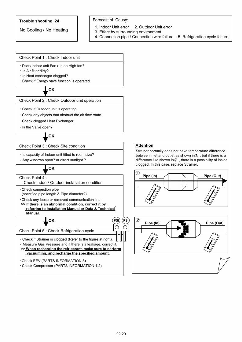
Attention
Trouble shooting 24 Forecast of Cause:
Check Point 2 : Check Outdoor unit operation
Check Point 1 : Check Indoor unit
Check Point 3 : Check Site condition
Check Point 5 : Check Refrigeration cycle
Check Point 4 : Check Indoor/ Outdoor installation condition
Pipe (In) Pipe (Out)
Pipe (In) Pipe (Out)
OKOK
OKOK
OKOK
OKOK
PSI PSI
No Cooling / No Heating1. Indoor Unit error 2. Outdoor Unit error 3. Effect by surrounding environment 4. Connection pipe / Connection wire failure 5. Refrigeration cycle failure
Does Indoor unit Fan run on High fan?Is Air filter dirty?Is Heat exchanger clogged?Check if Energy save function is operated.
Check if Outdoor unit is operating Check any objects that obstruct the air flow route.
Check clogged Heat Exchanger.
Is the Valve open?
Is capacity of Indoor unit fitted to room size?Any windows open? or direct sunlight ?
Check connection pipe (specified pipe length & Pipe diameter?)Check any loose or removed communication line.>> If there is an abnormal condition, correct it by referring to Installation Manual or Data & Technical Manual.
Check if Strainer is clogged (Refer to the figure at right).Measure Gas Pressure and if there is a leakage, correct it.
>> When recharging the refrigerant, make sure to perform vacuuming, and recharge the specified amount.
Check EEV (PARTS INFORMATION 3) Check Compressor (PARTS INFORMATION 1,2)
Strainer normally does not have temperature difference between inlet and outlet as shown in , but if there is a difference like shown in , there is a possibility of inside clogged. In this case, replace Strainer.
02-29

Trouble shooting 25 Forecast of Cause :
Trouble shooting 26 Forecast of Cause:
OKOK
OK
OK
OKOK
OKOK
OKOKPSI PSI
Abnormal Noise1. Abnormal installation (Indoor/ Outdoor) 2. Fan failure (Indoor/ Outdoor)3. Compressor failure (Outdoor)
Diagnosis method when abnormal noise is occurredAbnormal noise is coming from Indoor unit.(Check and correct followings)
Abnormal noise is coming from Outdoor unit.(Check and correct followings)
Is Fan broken or deformed?Is the screw of Fan loose?Is there any object which obstruct the Fan rotation?
Is Main unit installed in stable condition?Is the installation of air suction grille and front panel normal?
Is Fan broken or deformed?Is the screw of Fan loose?Is there any object which obstruct the Fan rotation?
Is Main unit installed in stable condition?Is Fan guard installed normally?
Check if vibration noise by loose bolt or contact noise of piping is happening.
Is Compressor locked?>> Check Compressor (PARTS INFORMATION 1,2)
Water Leaking 1. Erroneous installation 2. Drain hose failure
Diagnosis method when water is spitting out.
Is the filter clogged?
Check Gas pressure and correct it if there was a gas leak.
Diagnosis method when water leak occurs
Is Drain hose connection loose?Is there a trap in Drain hose?Is Drain hose clogged?
Is Main unit installed in stable condition?Is Main unit broken or deformed at the time of transportation or maintenance?
Is Fan rotating?
02-30

SERVICE PARTS INFORMATION 1
PSI PSI
Compressor
Diagnosis method of Compressor ( If Outdoor Unit LED displays Error, refer to Trouble shooting )
Does not start up
Is there open or loose connection cable?
Check Main PCB, connection of Compressor, and winding resistance. (Refer to the next page).
Check Main PCB, connection of Compressor,and winding resistance. (Refer to the next page).
>> If there is no failure, the defect of Compressor is considered (Locked compressor due to clogged dirt or less oil)
Replace Compressor
Replace Compressor
Replace Compressor
Stops soon after starting up
Is there open or loose connection cable?
Is Gas pipe valve open?(Low pressure is too low)
Check if Refrigerant is leaking.(Recharge Refrigerant)
Check if strainer is clogged.(PARTS INFORMATION 3)
>> If there is no failure, the defect of Compressor can be considered. (Compression part broken or valve defective.)
Abnormal noise
Defective Compressor can be considered.(due to inside dirt clogging or broken component)
Check if vibration noise by loose bolt or contact noise of piping is happening.
02-31
2-4 SERVICE PARTS INFORMATION

SERVICE PARTS INFORMATION 2
Check Point 1 : Check Connection
Check Point 2 : Check Winding Resistance
Check Point 3 : Replace Main PCB
C
SR
Compressor
Check terminal connection of Compressor(loose or incorrect wiring)
Check winding resistance of each terminalIf the resistance value is 0 or infinite, replace Compressor.
If the symptom does not change with above Check 1, 2, replace Main PCB.
02-32
R S (WHITE)
C(BLACK)Terminal cover opened
(RED)
AOU9/ 12/ 15RLFF
Resistance Value : 1.4 at 77°F(25°C)
AOU9 / 12RLFF
Resistance Value : 0.7 at 77°F(25°C)
AOU15RLFF

SERVICE PARTS INFORMATION 3
Check Point 2 : Check Coil of EEV
Yellow - Red
Orange - Red
Blue - Red
White - Red
Read wire
46 4
Resistance value
Check Point 1 : Check Connections
Check Point 5 : Check Opening and Closing Operation of Valve
Check Point 3 : Check Voltage from Main PCB.
Check Point 4 : Check Noise at start up
Pipe (In)
Pipe (Out)
Hi TEMP.Pipe (In)Hi TEMP.
Normal TEMP.
CLOSEExample : Hot Gas
OPENExample : Hot Gas
Pipe (Out)Hi TEMP.
Pipe (In) Pipe (Out)Pipe (In) Pipe (Out)
Check Point 6 : Check Strainer
DC
EXPANSIONVALVE COIL
EV
REDBLUEORANGEYELLOWWHITE
12345
at 68°F(20°C)
Outdoor unit Electronic Expansion Valve( EEV )
Check connection of connector (CN40 or CN700)( Loose connector or open cable )
Remove connector, check each winding resistance of Coil.
If Resistance value is abnormal, replace EEV.
Remove Connector and check Voltage (DC12V)If it does not appear, replace Main PCB.
Turn on Power and check operation noise.If an abnormal noise does not show, replace Main PCB.
When Valve is closed, it has a temp. difference between Inlet and Outlet.
If it is open, it has no temp. difference between Inlet and Outlet.
Strainer normally does not have temperature difference between inlet and outlet as shown in , but if there is a difference as shown in , there is a possibility of inside clogged. In this case, replace Strainer.
02-33
12345
CN40[9/12RLFF]
CN700[15RLFF]

SERVICE PARTS INFORMATION 5
Check Point 1 : Check rotation of Fan
Outdoor unit fan motor
Rotate the fan by hand when operation is off.(Check if fan is caught, dropped off or locked motor)>>If Fan or Bearing is abnormal, replace it.
Check Point 2 : Check resistance of Outdoor Fan Motor
Refer to below. Circuit-test "Vm" and "GND" terminal.(Vm: DC voltage, GND: Earth terminal)>>If they are short-circuited (below 300 k ), replace Outdoor fan motor and Main PCB.
Pin number (wire color)
Terminal function (symbol)
1 (Red)234 (Black)5 (White)6 (Yellow)7 (Brown)
DC voltage (Vm)No functionNo functionEarth terminal (GND)Control voltage (Vcc)Speed command (Vsp)Feed back (FG)
SERVICE PARTS INFORMATION 4
Check Point 1 : Check rotation of Fan
Indoor unit fan motor
Rotate the fan by hand when operation is off.(Check if fan is caught, dropped off or locked motor)>>If Fan or Bearing is abnormal, replace it.
Check Point 2 : Check resistance of Indoor Fan Motor
Refer to below. Circuit-test "Vm" and "GND" terminal.(Vm: DC voltage, GND: Earth terminal)>>If they are short-circuited (below 300 k ), replace Indoor fan motor and Controller PCB.
Pin number (wire color)
Terminal function (symbol)
1 (Blue)2 (Yellow)3 (White)4 (Black)56 (Red)
Feed back (FG)Speed command (Vsp)Control voltage (Vcc)Earth terminal (GND)No functionDC voltage (Vm)
02-34

SERVICE PARTS INFORMATION 6
Active filter module
02-35
For AOU15RLFF
Check Point 1 : Check Open or Short-circuit and Diode (D1)
Check Point 2 : Check the Output DC voltage (between P and N)
L2L1
P
N
+IN
Check the Output DC voltage (between P and N) of compressor stopping and operating.
If it is abnormal,replace ACTIVE FILTER MODULE
Remove connector, check the open or short-circuit and the diode in the module
>> If the output voltage of compressor operating is less than the output voltage of compressor stopping, Active Filter Module is detective. >> Replace Active Filter Module
TerminalResistance value
L2L1
L1,L2
P
P
Control Box
N
N
(+IN)
(+IN)
( IN)
( IN)
Tester(+) Tester(-)
Check the open or short-circuit
L2
P
P
NL2
L2
Check the diode
0
360k
720k
1.69M /
20%+-
20%+-
360k 20%+-
(Ref. value 1)1.88M(Ref. value 2)
1.40M /(Ref. value 1)
2.28M(Ref. value 2)
TerminalResistance value
Tester(+) Tester(-)
1.32M /(Ref. value 1)
1.50M(Ref. value 2)
1.40M /(Ref. value 1)
1.51M(Ref. value 2)
Ref. value 1Specifications for Multimeter Manufacturer : HIOKI Model name : 3804 Power source : DC9V.
Ref. value 2Specifications for Multimeter Manufacturer : YOKOGAWA Model name : 7534 Power source : DC3V.
-IN
By kind of tester, the value may change significantly.※
※
※
※
※

SERVICE PARTS INFORMATION 7IPM(Mounted on Transistor PCB)
02-36
Check Point 1
Check Point 2
Terminal Resistance value Tester(+) Tester(-)
Disconnect the connection wires between the Transistor PCB - Capacitor PCB and Transistor PCB - Inverter Compressor.
Set the tester to the "Resistance" mode, and measure the resistance between the following terminals.
Set the tester to the "Diode" mode, and measure the voltage value between the following terminals.
Judge the result of as follows:
Judge the result of as follows:
TM301 (P) - TM305(U) / TM304(V) / TM303(W)TM302 (N) - TM305(U) / TM304(V) / TM303(W)
PPPUVWNNNUVW
UVWPPPUVWNNN
Over 2k(Including )
Over 2k(Including )
Over 20k(Including )
Terminal Tester display Tester(+) Tester(-)
PPPUVWNNNUVW
UVWPPPUVWNNN
0.3V 0.7V
For AOU15RLFF

3 . APPENDING DATA
R410A
FLOOR typeINVERTER
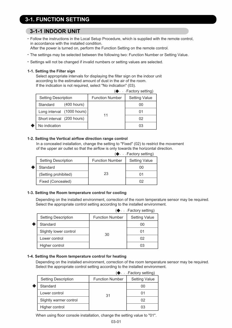
03-01
3-1. FUNCTION SETTING
Follow the instructions in the Local Setup Procedure, which is supplied with the remote control, in accordance with the installed condition.After the power is turned on, perform the Function Setting on the remote control.
The settings may be selected between the following two: Function Number or Setting Value.
Settings will not be changed if invalid numbers or setting values are selected.
3-1-1 INDOOR UNIT
( Factory setting)
Setting Description Function Number Setting Value
Standard
Long interval
Short interval
No indication
11
00
01
02
03
1-1. Setting the Filter signSelect appropriate intervals for displaying the filter sign on the indoor unit according to the estimated amount of dust in the air of the room. If the indication is not required, select "No indication" (03).
1-3. Setting the Room temperature control for cooling
( Factory setting)
Setting Description Function Number Setting Value
Standard
Slightly lower control
Lower control
Higher control
30
00
01
02
03
Depending on the installed environment, correction of the room temperature sensor may be required.Select the appropriate control setting according to the installed environment.
(400 hours)
(1000 hours)
(200 hours)
( Factory setting)Setting Description Function Number Setting Value
Standard
Lower control
Slightly warmer control
Higher control
31
00
01
02
03
1-4. Setting the Room temperature control for heatingDepending on the installed environment, correction of the room temperature sensor may be required.Select the appropriate control setting according to the installed environment.
When using floor console installation, change the setting value to "01".
( Factory setting)
Setting Description Function Number Setting Value
Standard
(Setting prohibited)
Fixed (Concealed)
2300
01
02
1-2. Setting the Vertical airflow direction range control In a concealed installation, change the setting to "Fixed" (02) to restrict the movement of the upper air outlet so that the airflow is only towards the horizontal direction.

03-02
1-5. Setting the Auto restartEnable or disable automatic restart after a power interruption.
( Factory setting)
Setting Description Function Number Setting Value
Enable
Disable40
00
01
* Auto restart is an emergency function such as for power outage etc. Do not attempt to use this function in normal operation. Be sure to operate the unit by remote controller or external input device.
1-6. Setting the Room temperature sensor switching (Only for Wired remote controller)
When using the Wired remote controller temperture sensor, change the setting to "Both" (01).( Factory setting)
Setting Description Function Number Setting Value
Indoor unit
Both42
00
01
* 00 : Sensor on the indoor unit is active.
* 01 : Sensors on both indoor unit and wired remote controller is active.
1-7. Setting the Remote controller signal code(Only for wireless remote controller)The indoor unit signal code can be changed. Select the appropriate signal code.
( Factory setting)Setting Description Function Number Setting Value
A
B
C
D
44
00
01
02
03
1-8. Setting the External input control"Operation/Stop" mode or "Forced stop" mode can be selected.
( Factory setting)Setting Description Function Number Setting Value
Operation /Stop mode
(Setting prohibited)
Forced stop mode
46
00
01
02
( Factory setting)Setting Description Function Number Setting Value
Disable
Enable49
00
01
1-9. Setting the Indoor unit fan control for energy saving for coolingEnables or disables the power-saving function by controlling the indoor unit fan rotation when the outdoor unit is stopped during cooling operation.
* If setting value is "00" : When the outdoor unit is stopped, the indoor unit fan operates continuously following the setting on the remote controller.* If setting value is "01" : When the outdoor unit is stopped, the indoor unit fan operates intermittently at a very low speed.

03-03
3-1-2 Procedures to change the Function Setting for wireless RC
CAUTION
After turning off the power, wait 10 seconds or more before turning on it again.The FUNCTION SETTING doesn't become active unlessthe power is turned off then on again.
Perform the “FUNCTION SETTING” according to the installation conditions using theremote controller. • This procedure changes to the function settings used to control the indoor unit
according to the installation conditions. Incorrect settings can cause the indoor unit tomalfunction.
• After the power is turned on, perform the “FUNCTION SETTING” according to theinstallation conditions using the remote controller
• The settings may be selected between the following two: Function Number or Setting Value. • Settings will not be changed if invalid numbers or setting values are selected.• Refer to the installation manual enclosed with the remote controller when the wired
remote controller (option) is used.
Entering the Function Setting ModeWhile pressing the POWERFUL button and SET TEMP.( ) button simultaneously, press the RESET button to enter the function setting mode. F
STEP 1Selecting the Remote Controller Custom CodeUse the following steps to select the custom code of the remote controller.(Note that the air conditioner cannot receive a custom code if the air conditioner has not been set for the custom code.)The custom codes that are set through this process are applicable onlyto the signals in the FUNCTION SETTING. For details on how to setthe custom codes through the normal process, refer to Remote controller custom code.
(1) Press SET TEMP.( ) button to change the custom code between Match the code on the display to the air conditioner custom code. (initially set to ) (If the custom code does not need to be selected, press the MIN.HEAT button and proceed to STEP 2.)
/
(2) Press the MODE button and check that the indoor unit can receive signals at the displayed custom code.
(3) Press the MIN.HEAT button to accept the custom code, and proceed to STEP 2.
The air conditioner custom code is set to A prior to shipment.Contact your retailer to change the custom code.
The remote controller resets to custom code A when the batteries in the remote controller are replaced. If you use a custom code other than custom code A, reset the custom code after replacing the batteries.If you do not know the air conditioner custom code setting, try each of the custom codes ( ) until you Þ nd the code which operates the air conditioner.
STEP 2Selecting the Function Number and Setting Value
(2) Press the POWERFUL button to proceed to setting value. (Press the POWERFUL button again to return to the function number selection.)
(3) Press the SET TEMP.( ) buttons to select the setting value. (Press the MIN. HEAT button to switch between the left and right digits.)
/
(4) Press the MODE button, and START/STOP button, in the orderl isted to confirm the settings.
(5) Press the RESET button to cancel the function setting mode.
(6) After completing the FUNCTION SETTING, be sureto turn off the power and turn it on again.
Function Number
Setting Value
(1) Press the SET TEMP. ( ) buttons to select the function number (Press the MIN. HEAT button to switch between the left and right digits.)
/
F

03-04
SET BACK
SU MO TU WE TH FR SA
SU MO TU WE TH FR SA
SU MO TU WE TH FR SA
(1) Press the SET TEMP. buttons ( ) ( ) and FAN button simultaneously for more than 5 seconds to enter the function setting mode.
(2) Press the SET BACK button to select the indoor unit number.
(3) Press the Set time buttons to select the function number.
(4) Press SET TEMP. buttons ( ) ( ) to select the setting value. The display flashes as shown to the right during setting value selection.
(7) After completing the FUNCTION SETTING, be sure to turn off the power and turn it on again.
(5) Press the TIMER SET button to confirm the setting. Press the TIMER SET button for a few seconds until the setting value stops flashing. If the setting value display changes or if "- -" is displayed when the flashing stops, the setting value has not been set correctly. (An invalid setting value may have been selected for the indoor unit.)
(6) Repeat steps 2 to 5 to perform additional settings. Press the SET TEMP. buttons ( ) ( ) and FAN button simultaneously again for more than 5 seconds to cancel the function setting mode. In addition, the function setting mode will be automatically canceled after 1 minute if no operation is performed.
Unit number of Indoor unit
Function number
SU MO TU WE TH FR SA
Setting value
FUNCTION SETTING METHOD (for Wired remote controller)
CAUTION
After turning off the power, wait 30 seconds or more before turning on it again.The FUNCTION SETTING doesn't become effective if it doesn't do so.
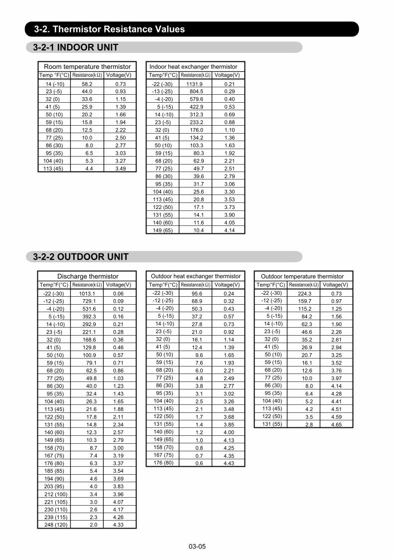
14 (-10) 58.2 0.73 -22 (-30) 1131.9 0.2123 (-5) 44.0 0.93 -13 (-25) 804.5 0.2932 (0) 33.6 1.15 -4 (-20) 579.6 0.4041 (5) 25.9 1.39 5 (-15) 422.9 0.5350 (10) 20.2 1.66 14 (-10) 312.3 0.6959 (15) 15.8 1.94 23 (-5) 233.2 0.8868 (20) 12.5 2.22 32 (0) 176.0 1.1077 (25) 10.0 2.50 41 (5) 134.2 1.3686 (30) 8.0 2.77 50 (10) 103.3 1.6395 (35) 6.5 3.03 59 (15) 80.3 1.92
104 (40) 5.3 3.27 68 (20) 62.9 2.21113 (45) 4.4 3.49 77 (25) 49.7 2.51
86 (30) 39.6 2.7995 (35) 31.7 3.06
104 (40) 25.6 3.30113 (45) 20.8 3.53122 (50) 17.1 3.73131 (55) 14.1 3.90140 (60) 11.6 4.05149 (65) 10.4 4.14
Room temperature thermistorTemp °F(°C) Resistance(k ) Voltage(V)
Indoor heat exchanger thermistorTemp°F(°C) Resistance(k ) Voltage(V)
Discharge thermistor Outdoor heat exchanger thermistor Outdoor temperature thermistor
03-05
3-2. Thermistor Resistance Values
3-2-1 INDOOR UNIT
3-2-2 OUTDOOR UNIT
-22 (-30) 1013.1 0.06-12 (-25) 729.1 0.09
-4 (-20) 531.6 0.125 (-15) 392.3 0.16
14 (-10) 292.9 0.2123 (-5) 221.1 0.2832 (0) 168.6 0.3641 (5) 129.8 0.4650 (10) 100.9 0.5759 (15) 79.1 0.7168 (20) 62.5 0.8677 (25) 49.8 1.0386 (30) 40.0 1.2395 (35) 32.4 1.43
104 (40) 26.3 1.65113 (45) 21.6 1.88122 (50) 17.8 2.11131 (55) 14.8 2.34140 (60) 12.3 2.57149 (65) 10.3 2.79158 (70) 8.7 3.00167 (75) 7.4 3.19176 (80) 6.3 3.37185 (85) 5.4 3.54194 (90) 4.6 3.69203 (95) 4.0 3.83212 (100) 3.4 3.96221 (105) 3.0 4.07230 (110) 2.6 4.17239 (115) 2.3 4.26248 (120) 2.0 4.33
Temp°F(°C) Resistance(k ) Voltage(V)
95.6 0.2468.9 0.3250.3 0.4337.2 0.5727.8 0.7321.0 0.9216.1 1.1412.4 1.39
9.6 1.657.6 1.936.0 2.214.8 2.493.8 2.773.1 3.022.5 3.262.1 3.481.7 3.681.4 3.851.2 4.001.0 4.130.8 4.250.7 4.350.6 4.43
Temp°F(°C) Resistance(k ) Voltage(V)
224.3 0.73159.7 0.97115.2 1.25
84.2 1.5662.3 1.9046.6 2.2635.2 2.6126.9 2.9420.7 3.2516.1 3.5212.6 3.7610.0 3.97
8.0 4.146.4 4.285.2 4.414.2 4.513.5 4.592.8 4.65
Temp°F(°C) Resistance(k ) Voltage(V)-22 (-30)-12 (-25)
-4 (-20)5 (-15)
14 (-10)23 (-5)32 (0)41 (5)50 (10)59 (15)68 (20)77 (25)86 (30)95 (35)
104 (40)113 (45)122 (50)131 (55)140 (60)149 (65)158 (70)167 (75)176 (80)
-22 (-30)-12 (-25)
-4 (-20)5 (-15)
14 (-10)23 (-5)32 (0)41 (5)50 (10)59 (15)68 (20)77 (25)86 (30)95 (35)
104 (40)113 (45)122 (50)131 (55)

1116,Suenaga,Takatsu-ku,Kawasaki 213-8502,Japan
November 2013 Printed in Japan


![Midea HK( Midea Air ) aa Air o Air 03 . Aurora ] Split Type Inverter Air—Conditioner ( Cooling ) wi9 Split Type Inverter Air-Conditioner ( Heating ) 3} ENERGY LABEL (Inverter) E-COtäit](https://static.fdocuments.in/doc/165x107/5fdb3873aa22060bcb5bb018/midea-hk-midea-air-aa-air-o-air-03-aurora-split-type-inverter-airaconditioner.jpg)