Split-to-the-shaft roller bearings · involved, Cooper split roller bearings are easier to install,...
188
Split-to-the-shaft roller bearings PRODUCT CATALOG
Transcript of Split-to-the-shaft roller bearings · involved, Cooper split roller bearings are easier to install,...
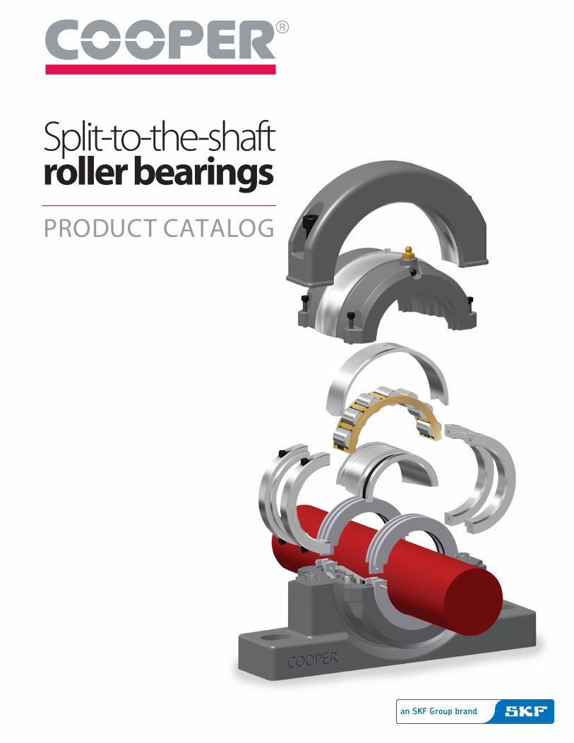
Split-to-the-shaftroller bearingsPRODUCT CATALOG
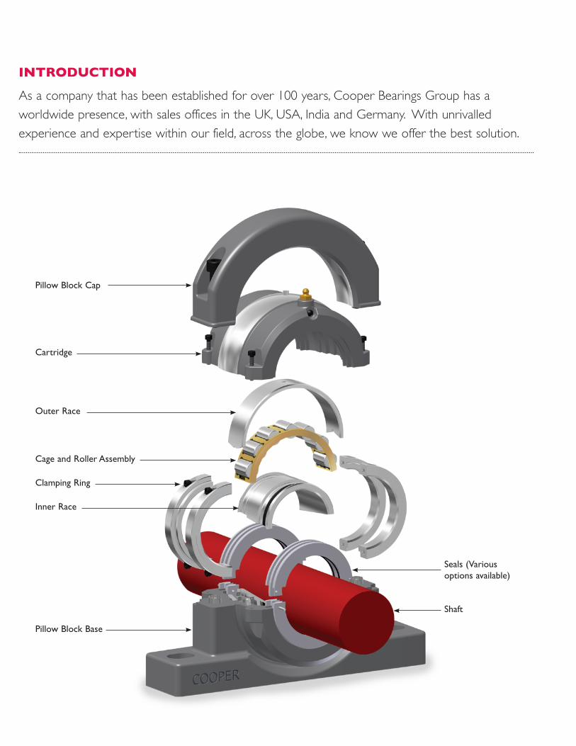
INTRODUCTION
As a company that has been established for over 100 years, Cooper Bearings Group has a worldwide presence, with sales offices in the UK, USA, India and Germany. With unrivalled experience and expertise within our field, across the globe, we know we offer the best solution.
Pillow Block Cap
Cartridge
Outer Race
Cage and Roller Assembly
Clamping Ring
Inner Race
Seals (Various options available)
Pillow Block Base
Shaft
WHAT IS THE SOLUTION?We provide totally split to the shaft roller bearings with totally split to the shaft components. Every Cooper component including bearing & cage assemblies, cartridges, pedestals, inner and outer races and our triple labyrinth seals are split to the shaft for easy installation. And, if we don’t already make it, our skilled Engineers can work with you to produce a custom made split roller bearing solution to solve your unique application problem.Ease of installation and maintenance makes the Cooper bearing an ideal solution for any application.
WHY SHOULD YOU CARE?With competition growing within your industry and margins being continually squeezed, we understand that for you and your customers achieving performance gains and running existing equipment to its full potential is increasingly important to stay ahead. We know that you or your customers can’t afford lost (or loss of) production time due to machinery downtime, whether it’s at scheduled maintenance times or through failures. The Cooper Bearings Group is always striving to provide you and your customers with the best value engineered products and solutions that will meet or exceed your needs.There is one proven answer to reducing production loss and machinery downtime expenses.That is the use of Cooper split roller bearings.
IS A SPLIT REALLY THE ANSWER?Are you looking for a bearing solution that offers a longer bearing life?In comparison to a solid bearing, Cooper split roller bearings are often better adapted to the sometimes harsh environment they are required to work in. The superior sealing of the Cooper triple labyrinth seal retains lubrication and keeps contaminants from entering the bearing assembly, providing a longer bearing life.Are you looking for a bearing solution that is easy to install and maintain?In comparison to a solid bearing, where trapped locations are involved, Cooper split roller bearings are easier to install, inspect and maintain. Other equipment on the shaft, such as pumps, motors and gearboxes that may be on either side of a bearing, does not need
to be removed for bearing replacement to take place. Due to the totally split components installation inspection and maintenance can be performed at a cost saving.Finally, do you want a bearing solution that isn’t going to cost a fortune?The Cooper split roller bearing reduces production downtime and reduces installation expenses as well as reducing power consumption.When the working life of a Cooper bearing is taken into account, the Cooper bearing is an extremely attractive investment.So if you’re tasked with increasing efficiency and cost savings, it’s job done with a Cooper split roller bearing!In the long run, Cooper offers a far more profitable solution compared to a solid, with far greater flexibility in design, ease of inspection, installation and maintenance solutions all without compromising performance.
SERVICE SECOND TO NONECooper's ability to resolve customers needs through the technical skills and resources of our in-house Engineering team and our strong customer service and field support teams, or through our established network of skilled supply-chain partners is a key component to our success.Cooper Bearings Group offers a range of services that can provide solutions to your specific bearing questions, conditions and problems.
• Our Engineering team can resolve technical issues rapidly and accurately addressing your maintenance and design needs
• Remanufacture & Repair services provide an economical solution to replacing with new
• Customer Service & Sales Specialist working to provide customers with solutions
• Emergency after-hours support available• E-Business technology through distributor support on
PTplace. Price & availability look-up 24/7• Product Training tailored to your audience offered at your
locationCooper Bearings Group is dedicated to our customers by supplying service offerings with solutions that provide operational efficiency and cost reductions that maximise uptime and performance with proven results and customer value.
CONTENTS
3 Overview of nomenclature
4-7 Bearing types
8 Bearing mounting options
9 Comparison of series
10 Joint gaps and internal clearances
11-13 Bearing selection
14-19 Radial load carrying capacity
20-21 Shaft tolerance and journal dimensions
22-24 Vibration data
25-27 Sealing solutions
28-29 Blanking plates
30-33 Lubrication
34-35 Standard bearings cartridges and pillow block to 24"/600mm bore size
36-53 Inch-size bearings, cartridges and pillow blocks
54-73 Metric bearings, cartridges and pillow blocks
74-75 Marine specification pillow blocks
76-82 Compatible pedestals
76 Type E compatible pillow blocks
77 SAF compatible pillow blocks
78 SN compatible pillow blocks
79-80 SD compatible pillow blocks
81-82 Quick-Change™ compatible pedestals
83-85 Flange - mounted units
86-92 Inch-size round flange-mounted units
93-99 Metric round flange-mounted units
100-101 Square flange-mounted units
102-103 Hanger bearing units
104-107 Inch size hanger bearing units
108-109 Metric hanger bearing units
110-111 Triple boss hanger bearing units
112 Take-up units
113-117 Inch size take-up push-type units
118-123 Inch size take-up tension-type units
124-129 Metric take-up push type units
130-131 Metric take-up tension type units
132 Rod-end bearing units
133-137 Inch - size rod - end bearing units T type
138-142 Inch - size rod end bearing units Shoe type
143-145 Metric rod - end bearing units T type
146-149 Metric rod end bearing units Shoe type
150-151 Bearings over 24”/600mm bore size
152 04 Series bearings
153 Water-cooled bearings for continuous casters
154 Special products
155 Split tapered bearings introduction
156 Bearing selection
157 Assembly - Grease quantity for initial lubrication
158 Routine greasing - Tightening torques
159 Bearing data
160 Cartridge data
161 Tapered bearing pedestal units
162 Tapered bearing flange units
Installation and assembly
163-166 Assembly instructions
167-171 Screw sizes, wrench sizes and torques
172-176 Grease quantities for initial lubrication
177-178 Routine greasing
179 What to do with your used bearing
180-181 Troubleshooting guide
182-185 Guidance on ordering and part codes
P2 www.CooperBearings.com
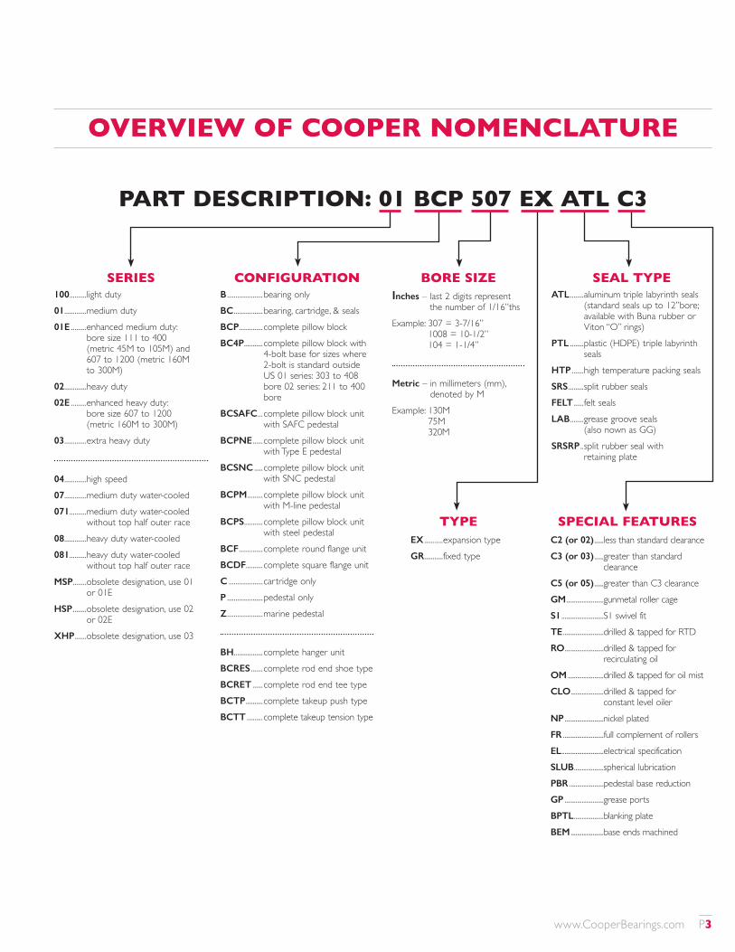
PART DESCRIPTION: 01 BCP 507 EX ATL C3
SERIES CONFIGURATION BORE SIZE
OVERVIEW OF COOPER NOMENCLATURE
100 ����������light duty01 �������������medium duty01E ���������enhanced medium duty:
bore size 111 to 400 (metric 45M to 105M) and 607 to 1200 (metric 160M to 300M)
02 �������������heavy duty02E ���������enhanced heavy duty:
bore size 607 to 1200 (metric 160M to 300M)
03 �������������extra heavy duty
04 �������������high speed07 �������������medium duty water-cooled071 ����������medium duty water-cooled
without top half outer race08 �������������heavy duty water-cooled081 ����������heavy duty water-cooled
without top half outer raceMSP��������obsolete designation, use 01
or 01EHSP ��������obsolete designation, use 02
or 02EXHP �������obsolete designation, use 03
SEAL TYPEATL ��������aluminum triple labyrinth seals
(standard seals up to 12”bore; available with Buna rubber or Viton “O” rings)
PTL ��������plastic (HDPE) triple labyrinth seals
HTP �������high temperature packing sealsSRS ���������split rubber sealsFELT ������felt sealsLAB ��������grease groove seals
(also nown as GG)SRSRP ��split rubber seal with
retaining plate
B ���������������������bearing onlyBC �����������������bearing, cartridge, & sealsBCP ��������������complete pillow blockBC4P �����������complete pillow block with
4-bolt base for sizes where 2-bolt is standard outside US 01 series: 303 to 408 bore 02 series: 211 to 400 bore
BCSAFC ���complete pillow block unit with SAFC pedestal
BCPNE ������complete pillow block unit with Type E pedestal
BCSNC �����complete pillow block unit with SNC pedestal
BCPM ���������complete pillow block unit with M-line pedestal
BCPS �����������complete pillow block unit with steel pedestal
BCF ��������������complete round flange unitBCDF����������complete square flange unitC ��������������������cartridge onlyP ���������������������pedestal onlyZ ���������������������marine pedestal
BH �����������������complete hanger unitBCRES �������complete rod end shoe typeBCRET ������complete rod end tee typeBCTP ����������complete takeup push typeBCTT ���������� complete takeup tension type
SPECIAL FEATURESC2 (or 02) ������less than standard clearanceC3 (or 03) ������greater than standard
clearanceC5 (or 05) ������greater than C3 clearanceGM ������������������������gunmetal roller cageS1 ���������������������������S1 swivel fitTE ��������������������������drilled & tapped for RTDRO �������������������������drilled & tapped for
recirculating oilOM �����������������������drilled & tapped for oil mistCLO ���������������������drilled & tapped for
constant level oilerNP �������������������������nickel platedFR ��������������������������full complement of rollersEL ���������������������������electrical specificationSLUB �������������������spherical lubricationPBR ����������������������pedestal base reductionGP �������������������������grease portsBPTL �������������������blanking plateBEM ���������������������base ends machined
Inches – last 2 digits represent the number of 1/16”ths
Example: 307 = 3-7/16” 1008 = 10-1/2” 104 = 1-1/4”
Metric – in millimeters (mm), denoted by M
Example: 130M 75M 320M
TYPEEX �����������expansion typeGR �����������fixed type
www�CooperBearings�com P3
Bearing Types
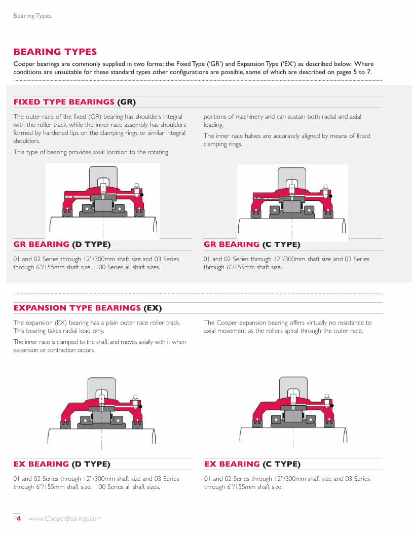
EXPANSION TYPE BEARINGS (EX)
The expansion (EX) bearing has a plain outer race roller track. This bearing takes radial load only.The inner race is clamped to the shaft, and moves axially with it when expansion or contraction occurs.
The Cooper expansion bearing offers virtually no resistance to axial movement as the rollers spiral through the outer race.
FIXED TYPE BEARINGS (GR)
The outer race of the fixed (GR) bearing has shoulders integral with the roller track, while the inner race assembly has shoulders formed by hardened lips on the clamping rings or similar integral shoulders.This type of bearing provides axial location to the rotating
portions of machinery and can sustain both radial and axial loading.The inner race halves are accurately aligned by means of fitted clamping rings.
GR BEARING (D TYPE)
01 and 02 Series through 12”/300mm shaft size and 03 Series through 6”/155mm shaft size. 100 Series all shaft sizes.
GR BEARING (C TYPE)
01 and 02 Series through 12”/300mm shaft size and 03 Series through 6”/155mm shaft size.
EX BEARING (D TYPE)
01 and 02 Series through 12”/300mm shaft size and 03 Series through 6”/155mm shaft size. 100 Series all shaft sizes.
EX BEARING (C TYPE)
01 and 02 Series through 12”/300mm shaft size and 03 Series through 6”/155mm shaft size.
BEARING TYPESCooper bearings are commonly supplied in two forms: the Fixed Type (‘GR’) and Expansion Type (‘EX’) as described below. Where conditions are unsuitable for these standard types other configurations are possible, some of which are described on pages 5 to 7.
P4 www.CooperBearings.com
Bearing Types
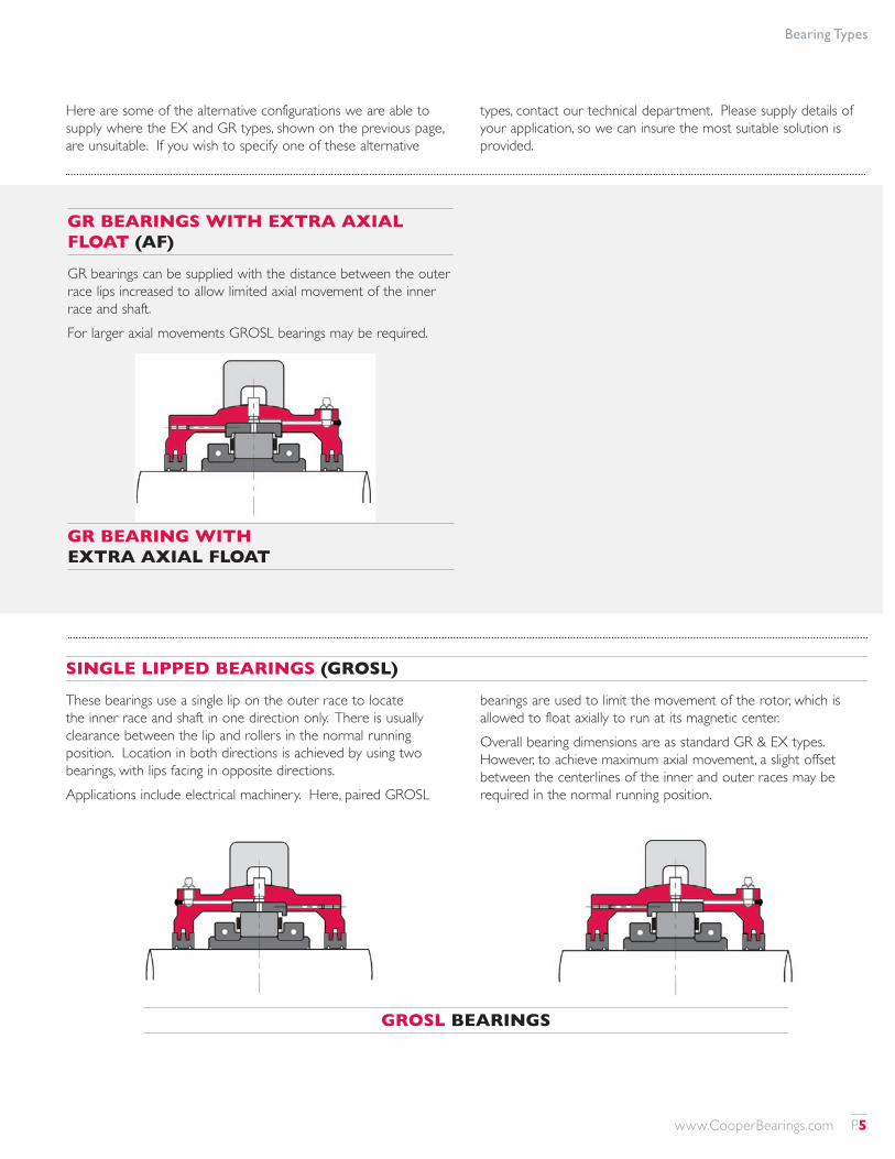
GR BEARINGS WITH EXTRA AXIAL FLOAT (AF)
GR bearings can be supplied with the distance between the outer race lips increased to allow limited axial movement of the inner race and shaft.For larger axial movements GROSL bearings may be required.
GROSL BEARINGS
GR BEARING WITH EXTRA AXIAL FLOAT
SINGLE LIPPED BEARINGS (GROSL)
These bearings use a single lip on the outer race to locate the inner race and shaft in one direction only. There is usually clearance between the lip and rollers in the normal running position. Location in both directions is achieved by using two bearings, with lips facing in opposite directions.Applications include electrical machinery. Here, paired GROSL
bearings are used to limit the movement of the rotor, which is allowed to float axially to run at its magnetic center.Overall bearing dimensions are as standard GR & EX types. However, to achieve maximum axial movement, a slight offset between the centerlines of the inner and outer races may be required in the normal running position.
Here are some of the alternative configurations we are able to supply where the EX and GR types, shown on the previous page, are unsuitable. If you wish to specify one of these alternative
types, contact our technical department. Please supply details of your application, so we can insure the most suitable solution is provided.
www.CooperBearings.com P5
Bearing Types
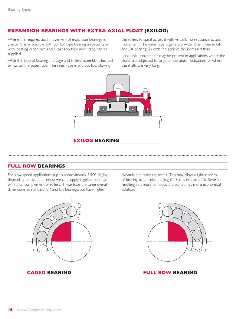
EXPANSION BEARINGS WITH EXTRA AXIAL FLOAT (EXILOG)
Where the required axial movement of expansion bearings is greater than is possible with our EX type bearing a special type, with locating outer race and expansion type inner race, can be supplied.With this type of bearing, the cage and rollers’ assembly is located by lips on the outer race. The inner race is without lips, allowing
the rollers to spiral across it with virtually no resistance to axial movement. The inner race is generally wider than those in GR and EX bearings, in order to achieve the increased float.Large axial movements may be present in applications where the shafts are subjected to large temperature fluctuations or where the shafts are very long.
FULL ROW BEARINGS
For slow speed applications (up to approximately 5,900 dn(in), depending on size and series) we can supply cageless bearings with a full complement of rollers. These have the same overall dimensions as standard GR and EX bearings, but have higher
dynamic and static capacities. This may allow a lighter series of bearing to be selected (e.g. 01 Series instead of 02 Series) resulting in a more compact, and sometimes more economical solution.
CAGED BEARING
EXILOG BEARING
FULL ROW BEARING
P6 www.CooperBearings.com
Bearing Types
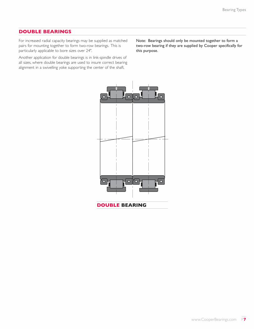
DOUBLE BEARING
DOUBLE BEARINGS
For increased radial capacity bearings may be supplied as matched pairs for mounting together to form two-row bearings. This is particularly applicable to bore sizes over 24".Another application for double bearings is in link-spindle drives of all sizes, where double bearings are used to insure correct bearing alignment in a swivelling yoke supporting the center of the shaft.
Note: Bearings should only be mounted together to form a two-row bearing if they are supplied by Cooper specifically for this purpose.
www.CooperBearings.com P7
Bearing Mounting Options
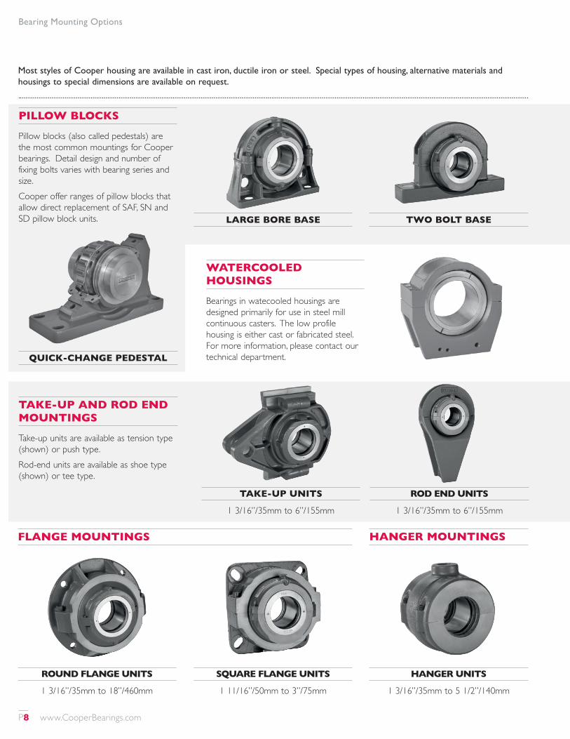
Most styles of Cooper housing are available in cast iron, ductile iron or steel. Special types of housing, alternative materials and housings to special dimensions are available on request.
TAKE-UP AND ROD END MOUNTINGS
Take-up units are available as tension type (shown) or push type.Rod-end units are available as shoe type (shown) or tee type.
TAKE-UP UNITS
1 3/16”/35mm to 6”/155mm
ROD END UNITS
1 3/16”/35mm to 6”/155mm
PILLOW BLOCKS
Pillow blocks (also called pedestals) are the most common mountings for Cooper bearings. Detail design and number of fixing bolts varies with bearing series and size.Cooper offer ranges of pillow blocks that allow direct replacement of SAF, SN and SD pillow block units.
WATERCOOLED HOUSINGS
Bearings in watecooled housings are designed primarily for use in steel mill continuous casters. The low profile housing is either cast or fabricated steel. For more information, please contact our technical department.
LARGE BORE BASE TWO BOLT BASE
QUICK-CHANGE PEDESTAL
FLANGE MOUNTINGS
ROUND FLANGE UNITS
1 3/16”/35mm to 18”/460mm
SQUARE FLANGE UNITS
1 11/16”/50mm to 3”/75mm
HANGER UNITS
1 3/16”/35mm to 5 1/2”/140mm
HANGER MOUNTINGS
P8 www.CooperBearings.com
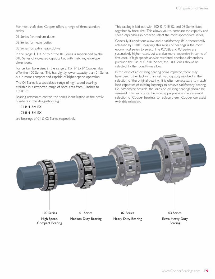
100 Series
High Speed, Compact Bearing
01 Series
Medium Duty Bearing
02 Series
Heavy Duty Bearing
03 Series
Extra Heavy Duty Bearing
Comparison of Series
For most shaft sizes Cooper offers a range of three standard series:01 Series for medium duties02 Series for heavy duties03 Series for extra heavy dutiesIn the range 1 11/16” to 4" the 01 Series is superseded by the 01E Series of increased capacity, but with matching envelope dimensions.For certain bore sizes in the range 2 15/16” to 6" Cooper also offer the 100 Series. This has slightly lower capacity than 01 Series but is more compact and capable of higher speed operation.The 04 Series is a specialized range of high speed bearings available in a restricted range of bore sizes from 6 inches to 1550mm.Bearing references contain the series identification as the prefix numbers in the designation, e.g.:
01 B 415M EX
02 B 415M EX
are bearings of 01 & 02 Series respectively.
This catalog is laid out with 100, 01/01E, 02 and 03 Series listed together by bore size. This allows you to compare the capacity and speed capabilities, in order to select the most appropriate series.Generally, if conditions allow and a satisfactory life is theoretically achieved by 01/01E bearings, this series of bearings is the most economical series to select. The 02/02E and 03 Series are successively higher rated, but are also more expensive in terms of first cost. If high speeds and/or restricted envelope dimensions preclude the use of 01/01E Series, the 100 Series should be selected if other conditions allow.In the case of an existing bearing being replaced, there may have been other factors than just load capacity involved in the selection of the original bearing. It is often unnecessary to match load capacities of existing bearings to achieve satisfactory bearing life. Wherever possible, the loads on existing bearings should be assessed. This will insure the most appropriate and economical selection of Cooper bearings to replace them. Cooper can assist with this selection.
www.CooperBearings.com P9
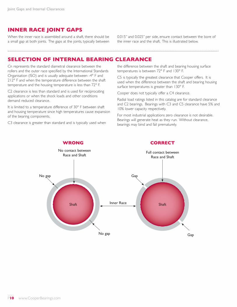
Joint Gaps and Internal Clearances
INNER RACE JOINT GAPSWhen the inner race is assembled around a shaft, there should be a small gap at both joints. The gaps at the joints, typically between
0.015” and 0.025” per side, ensure contact between the bore of the inner race and the shaft. This is illustrated below.
SELECTION OF INTERNAL BEARING CLEARANCECn represents the standard diametral clearance between the rollers and the outer race specified by the International Standards Organisation (ISO) and is usually adequate between -4° F and 212° F and when the temperature difference between the shaft temperature and the housing temperature is less than 72° F.C2 clearance is less than standard and is used for reciprocating applications or when the shock loads and other conditions demand reduced clearance. It is limited to a temperature difference of 30° F between shaft and housing temperature since high temperatures cause expansion of the bearing components.C3 clearance is greater than standard and is typically used when
the difference between the shaft and bearing housing surface temperatures is between 72° F and 130° F.C5 is typically the greatest clearance that Cooper offers. It is used when the difference between the shaft and bearing housing surface temperatures is greater than 130° F.Cooper does not typically offer a C4 clearance. Radial load ratings listed in this catalog are for standard clearance and C2 bearings. Bearings with C3 and C5 clearance have 5% and 10% lower capacity respectively.For most industrial applications zero clearance is not desirable. Bearings will generate heat as they run. Without clearance, bearings may bind and fail prematurely.
WRONG CORRECT
Full contact between Race and Shaft
No contact between Race and Shaft
No gap
No gap
Inner Race
Gap
Gap
ShaftShaft
P10 www.CooperBearings.com
Bearing Selection
BEARING SELECTIONSelection of Cooper bearings must take into account both radial and axial loads, which are considered independently as the effect of the axial load on the radial load-bearing surfaces is small enough to discount at normal working loads and speeds.The thrust or axial load is taken by the end face of the rollers and the flanged shoulders of the inner race assembly and outer race. The ability of the fixed (GR) unit to handle thrust loads is dependent upon specific pressure, velocity of contact areas and lubrication.
CALCULATING BEARING LOADSThe bearing loads are affected by one or more of the following:1. Weight of components such as shafting, flywheels, sheaves,
pulleys, gears, etc.2. Tension resulting from belt or chain drives.3. Tangential, separating and axial loading developed by gears.4. Inertia loading resulting from acceleration or deceleration.5. Centrifugal forces developed in rotary or out of balance
motion.
SELECTION FOR RADIAL LOADThe radial load ratings listed in this catalog are based on ISO standards. The system establishes a common basis for calculating load ratings for all anti-friction bearings. The radial load rating is denoted by Cr.
Selection for radial load is determined independently from the axial load. Determine the radial load, speed and minimum life required. Generally the shaft size has been predetermined. Selection of the bearing can be made using the following formula:Cr ≥ P x fn x fl x fd.Where Cr = radial dynamic rating. P = calculated effective radial load. fn = speed (rpm) factor.fl = life (hours) factor.fd = dynamic or service factor.fn = (rpm x 0.03)0.3 or find from scale on page 13.fl = (L10 hours/500)0.3 or find from scale on page 13.L10 hours is the expected life in hours of 90% of similar bearings under similar operating conditions.Note: the product fn x fl should not be less than 1.0.Alternatively, bearing life may be calculated by the equation L10 = [Cr/(P x fd)]10/3, where: L10 = expected life of 90% of similar bearings under similar operating conditions, in millions of revolutions.When the equivalent radial load equals the Cr rating, multiplied by the service factor, the L10 life will be 1 million revolutions.If high temperatures (above 212° F) are involved, please refer to notes on page 13.
www.CooperBearings.com P11
Bearing Selection
BEARING LIFE REQUIREMENTS (L)Suggested lives and factors for specific operating conditions are shown below.
Operating Conditions Life factor Life hours
(fL) (L10)
8 hour daily working 3.0-4.0 20,000- 50,000Continuous operation main drives, large electrical machinery, flywheels, mining
4.4-5.0 70,000-100,000
Continuous operation and an exceptionally high degree of reliability
5.0-6.0 100,000-200,000
We recommend that bearings are specified to provide an L10 life of at least 10,000 hours, except for bearings selected on the basis of static rating.
DYNAMIC FACTORThe appropriate dynamic factor fd may be taken from the chart below.Conditions fd
Steady load or small fluctuations 1.0 - 1.3Light shock 1.3 - 2.0Heavy shock, vibration or reciprocation 2.0 - 3.5
LIFE ADJUSTMENT FACTORS FOR CRITICAL APPLICATIONSThe basic L10 life obtained by using the equations or tables in this catalogue are adequate for normal applications. Bearings for most normal applications are specified using the L10 life as above. For reliabilty greater than 90%, replace L10 in the above equations with Lna where Lna = a1 x L10 and is given in the table below.Reliability
% 95 96 97 98 99a1 0.62 0.53 0.44 0.33 0.21
MINIMUM RADIAL LOAD The radial load must exceed a certain value in order to prevent the rollers skidding rather than rolling. Cooper bearings are able to operate at lower loads than other types of rolling element bearings. Minimum radial loads are generally Cr/65 for GR bearings and Cr/120 for EX bearings. Lower loads can be accommodated under certain conditions. Please refer to our technical department.
BASIC STATIC LOAD RATINGS (COR)The values of Cor given in this publication have been calculated in accordance with ISO standards. The basic static load rating is defined as that static (radial) load which corresponds to a contact stress of 4,000 MPa (580,000 psi) at the center of the most heavily loaded roller/raceway contact and produces a permanent deformation of 0.0001 times the roller diameter. Where rotation is very slow (less than 5 rpm) or intermittent, bearing size can be selected based on the static load carrying capacity. The requisite basic static load rating can be determined from:Cor = So x P where:
Cor = basic static radial load rating (kN)P = effective bearing load (kN)So = static safety factor
Bearing Static Safety Factors, So
Type of operation Requirements for smooth runningLow Normal High
Vibration free 1 1.5 3Normal 1 2 3.5High shock loads 2.5 3 4
P12 www.CooperBearings.com
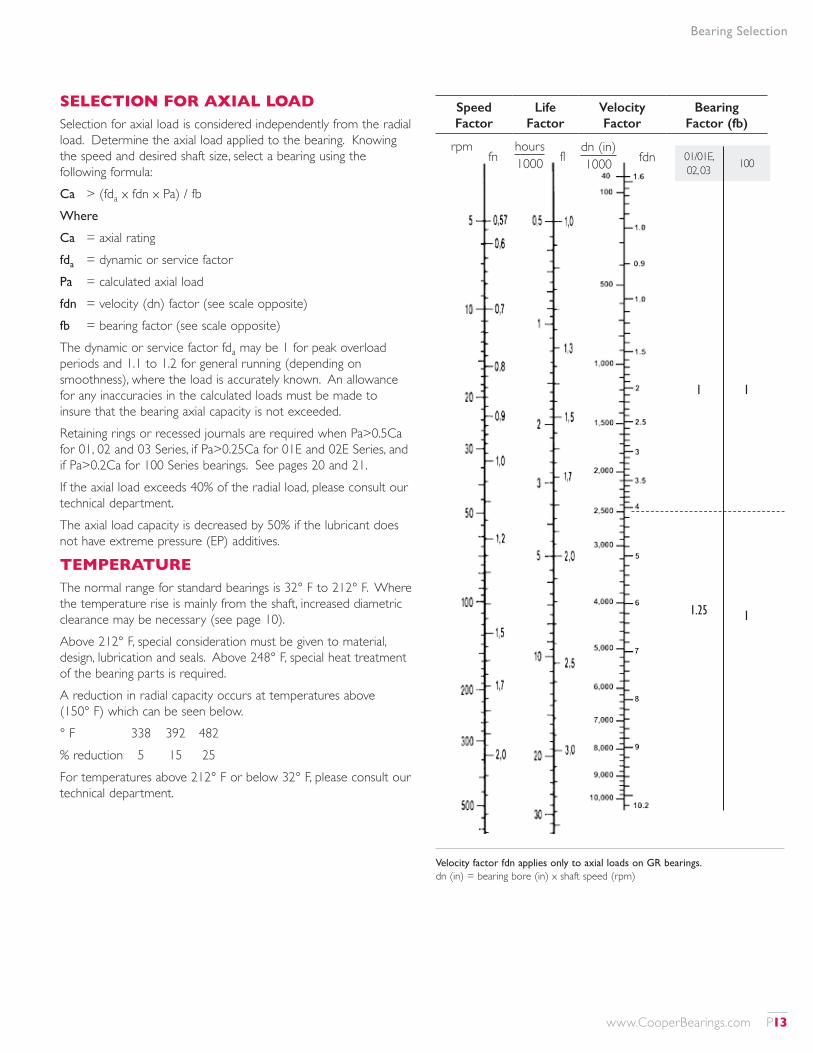
SELECTION FOR AXIAL LOADSelection for axial load is considered independently from the radial load. Determine the axial load applied to the bearing. Knowing the speed and desired shaft size, select a bearing using the following formula:Ca > (fda x fdn x Pa) / fb Where
Ca = axial ratingfda = dynamic or service factorPa = calculated axial loadfdn = velocity (dn) factor (see scale opposite)fb = bearing factor (see scale opposite)The dynamic or service factor fda may be 1 for peak overload periods and 1.1 to 1.2 for general running (depending on smoothness), where the load is accurately known. An allowance for any inaccuracies in the calculated loads must be made to insure that the bearing axial capacity is not exceeded.Retaining rings or recessed journals are required when Pa>0.5Ca for 01, 02 and 03 Series, if Pa>0.25Ca for 01E and 02E Series, and if Pa>0.2Ca for 100 Series bearings. See pages 20 and 21.If the axial load exceeds 40% of the radial load, please consult our technical department. The axial load capacity is decreased by 50% if the lubricant does not have extreme pressure (EP) additives.
TEMPERATUREThe normal range for standard bearings is 32° F to 212° F. Where the temperature rise is mainly from the shaft, increased diametric clearance may be necessary (see page 10).Above 212° F, special consideration must be given to material, design, lubrication and seals. Above 248° F, special heat treatment of the bearing parts is required.A reduction in radial capacity occurs at temperatures above (150° F) which can be seen below.° F 338 392 482% reduction 5 15 25For temperatures above 212° F or below 32° F, please consult our technical department.
Bearing Selection
Velocity factor fdn applies only to axial loads on GR bearings.dn (in) = bearing bore (in) x shaft speed (rpm)
01/01E, 02, 03 100
1 1
1.25 1
hours1000fn
rpm dn (in)1000fl fdn
Speed Factor
Life Factor
Velocity Factor
Bearing Factor (fb)
www.CooperBearings.com P13
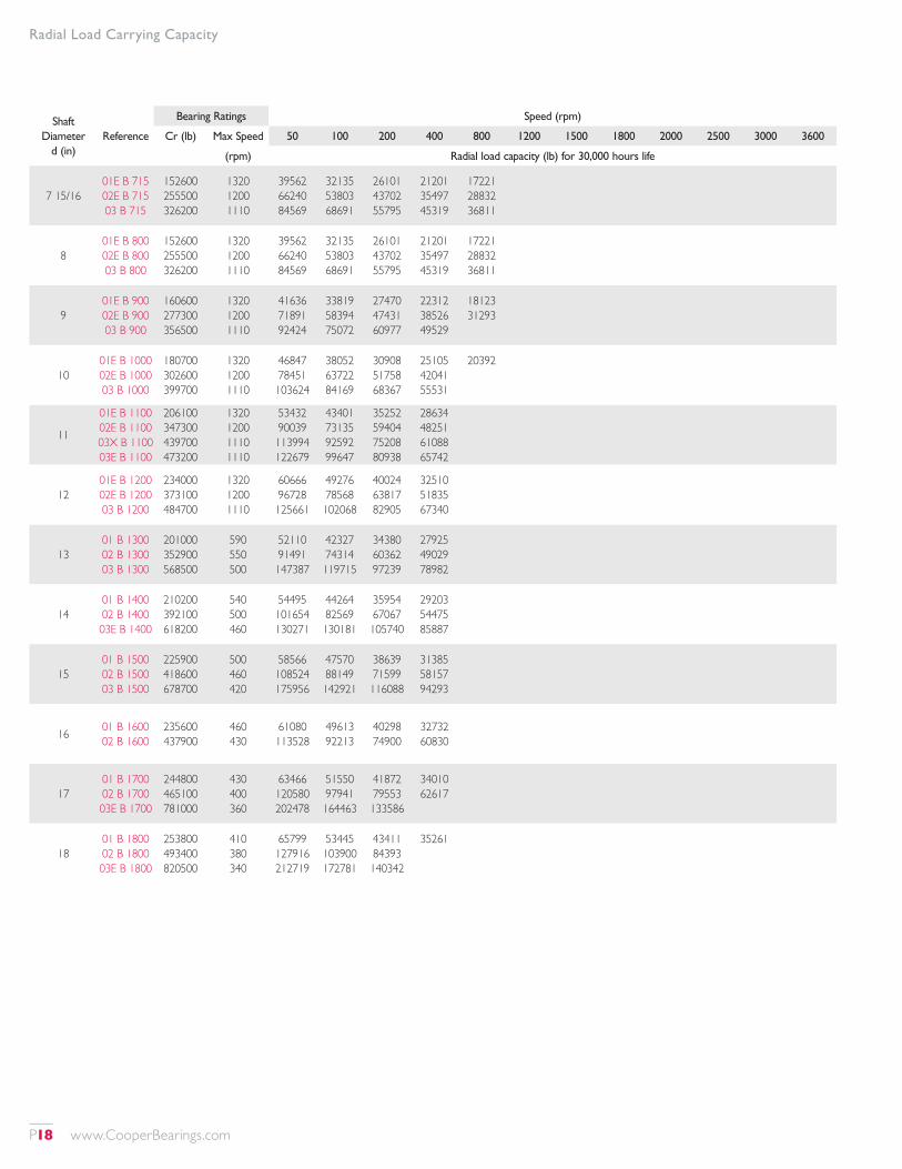
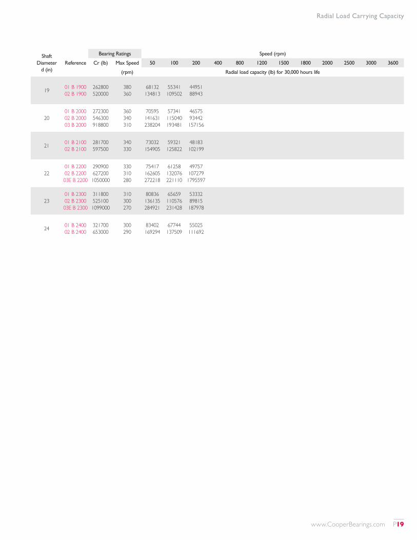
Radial Load Carrying Capacity
RADIAL LOAD CARRYING CAPACITY QUICK REFERENCE TABLEThe table on the following pages is a rapid means of selection for radial load, based on a statistical fatigue life (L10) of 30,000 hours at selected speeds. This life is often specified in general applications working approximately 8 hours per day.No dynamic factor (fd) is included in the values given. For most applications, the loads given should be divided by a dynamic factor as specified on page 12.For 100,000 hours life, divide the loads in the table by 1.435, and then divide by the appropriate service factor.
The capacities shown in this table are for the bearing only. In most cases the load carrying capacity of the relevant housing exceeds the bearing capacity shown in this table, but should be checked by reference to the appropriate section of this catalog or confirmed by our technical department.For a more detailed explanation of bearing selection, and for conditions not covered by this table, see page 11.Fixed-type (GR) bearings carrying axial loads should be checked for axial load carrying capacity by reference to page 13.
P14 www.CooperBearings.com
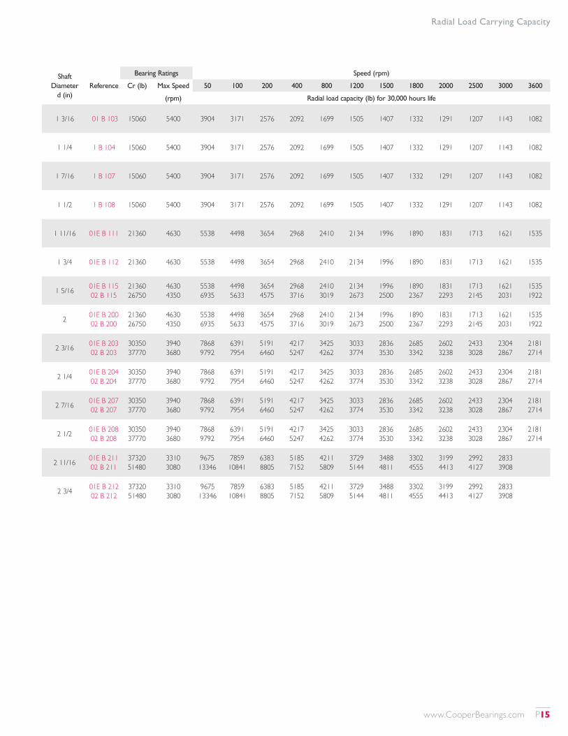
Radial Load Carrying Capacity
Shaft Diameter
d (in)Reference
Bearing Ratings Speed (rpm)
Cr (lb) Max Speed 50 100 200 400 800 1200 1500 1800 2000 2500 3000 3600
(rpm) Radial load capacity (lb) for 30,000 hours life
1 3/16 01 B 103 15060 5400 3904 3171 2576 2092 1699 1505 1407 1332 1291 1207 1143 1082
1 1/4 1 B 104 15060 5400 3904 3171 2576 2092 1699 1505 1407 1332 1291 1207 1143 1082
1 7/16 1 B 107 15060 5400 3904 3171 2576 2092 1699 1505 1407 1332 1291 1207 1143 1082
1 1/2 1 B 108 15060 5400 3904 3171 2576 2092 1699 1505 1407 1332 1291 1207 1143 1082
1 11/16 01E B 111 21360 4630 5538 4498 3654 2968 2410 2134 1996 1890 1831 1713 1621 1535
1 3/4 01E B 112 21360 4630 5538 4498 3654 2968 2410 2134 1996 1890 1831 1713 1621 1535
1 5/16 01E B 115 02 B 115
21360 26750
4630 4350
5538 6935
4498 5633
3654 4575
2968 3716
2410 3019
2134 2673
1996 2500
1890 2367
1831 2293
1713 2145
1621 2031
1535 1922
2 01E B 200 02 B 200
21360 26750
4630 4350
5538 6935
4498 5633
3654 4575
2968 3716
2410 3019
2134 2673
1996 2500
1890 2367
1831 2293
1713 2145
1621 2031
1535 1922
2 3/16 01E B 203 02 B 203
30350 37770
3940 3680
7868 9792
6391 7954
5191 6460
4217 5247
3425 4262
3033 3774
2836 3530
2685 3342
2602 3238
2433 3028
2304 2867
2181 2714
2 1/4 01E B 204 02 B 204
30350 37770
3940 3680
7868 9792
6391 7954
5191 6460
4217 5247
3425 4262
3033 3774
2836 3530
2685 3342
2602 3238
2433 3028
2304 2867
2181 2714
2 7/16 01E B 207 02 B 207
30350 37770
3940 3680
7868 9792
6391 7954
5191 6460
4217 5247
3425 4262
3033 3774
2836 3530
2685 3342
2602 3238
2433 3028
2304 2867
2181 2714
2 1/2 01E B 208 02 B 208
30350 37770
3940 3680
7868 9792
6391 7954
5191 6460
4217 5247
3425 4262
3033 3774
2836 3530
2685 3342
2602 3238
2433 3028
2304 2867
2181 2714
2 11/16 01E B 211 02 B 211
37320 51480
3310 3080
9675 13346
7859 10841
6383 8805
5185 7152
4211 5809
3729 5144
3488 4811
3302 4555
3199 4413
2992 4127
2833 3908
2 3/4 01E B 212 02 B 212
37320 51480
3310 3080
9675 13346
7859 10841
6383 8805
5185 7152
4211 5809
3729 5144
3488 4811
3302 4555
3199 4413
2992 4127
2833 3908
www.CooperBearings.com P15
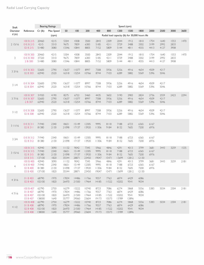
Radial Load Carrying Capacity
Shaft Diameter
d (in)Reference
Bearing Ratings Speed (rpm)
Cr (lb) Max Speed 50 100 200 400 800 1200 1500 1800 2000 2500 3000 3600
(rpm) Radial load capacity (lb) for 30,000 hours life
2 15/16100 B 215 01E B 215 02 B 215
20460 4215 51480
4215 3310 3080
5304 9675 13346
4308 7859 10841
3500 6383 8805
2843 5185 7152
2309 4211 5809
2044 3729 5144
1912 3488 4811
1810 3302 4555
1754 3199 4413
1640 2992 4127
1553 2833 3908
1470
3100 B 300 01E B 300 2 B 300
20460 37320 51480
4215 3310 3080
5304 9675 13346
4308 7859 10841
3500 6383 8805
2843 5185 7152
2309 4211 5809
2044 3729 5144
1912 3488 4811
1810 3302 4555
1754 3199 4413
1640 2992 4127
1553 2833 3908
1470
3 3/16 01E B 303 02 B 303
52600 62940
2790 2520
13637 16318
11077 13254
8997 10766
7308 8744
5936 7103
5256 6289
4916 5882
4654 5569
4509 5396
4217 5046
3 1/4 01E B 304 02 B 304
52600 62940
2790 2520
13637 16318
11077 13254
8997 10766
7308 8744
5936 7103
5256 6289
4916 5882
4654 5569
4509 5396
4217 5046
3 7/16100 B 307 01E B 307 2 B 307
31920 52600 62940
4190 2790 2520
8275 13637 16318
6722 11077 13254
5460 8997 10766
4435 7308 8744
3602 5936 7103
3190 5256 6289
2983 4916 5882
2824 4654 5569
2736 4509 5396
2559 4217 5046
2423
2294
3 1/2 01E B 308 02 B 308
52600 62940
2790 2520
13637 16318
11077 13254
8997 10766
7308 8744
5936 7103
5256 6289
4916 5882
4654 5569
4509 5396
4217 5046
3 11/16 01E B 311 02 B 311
71940 81380
2340 2130
18651 21098
15149 17137
12305 13920
9995 11306
8118 9184
7188 8132
6723 7605
6365 7200
6167 6976
3 3/4 01E B 312 02 B 312
71940 81380
2340 2130
18651 21098
15149 17137
12305 13920
9995 11306
8118 9184
7188 8132
6723 7605
6365 7200
6167 6976
3 15/16
100 B 315 01E B 315 02 B 315 03 B 315
42940 71940 81380 137100
3090 2340 2130 1820
11132 18651 21098 35544
9042 15149 17137 28871
7345 12305 13920 23450
5966 9995 11306 19047
4846 8118 9184 15471
4291 7188 8132 13699
4013 6723 7605 12812
3799 6365 7200 12130
3681 6167 6976
3443
3259
1535
4
100 B 400 01E B 400 02 B 400 03 B 400
42940 71940 81380 137100
3090 2340 2130 1820
11132 18651 21098 35544
9042 15149 17137 28871
7345 12305 13920 23450
5966 9995 11306 19047
4846 8118 9184 15471
4291 7188 8132 13699
4013 6723 7605 12812
3799 6365 7200 12130
3681 6167 6976
3443
3259
2181
4 3/16 01 B 403 02 B 403
68790 102100
1970 1820
17834 26470
14486 21500
11766 17464
9557 14185
7763 11522
6874 10202
6429 9541
6086 9034
4 7/16
100 B 407 01 B 407 02 B 407 03 B 407
62790 68790 102100 138000
2750 1970 1820 1640
16279 17834 26470 35777
13222 14486 21500 29060
10740 11766 17464 23604
8723 9557 14185 19173
7086 7763 11522 15573
6274 6874 10202 13789
5868 6429 9541 12896
5556 6086 9034
5383
5034
2304
2181
4 1/2
100 B 408 01 B 408 02 B 408 03 B 408
62790 68790 102100 138000
2750 1970 1820 1640
16279 17834 26470 35777
13222 14486 21500 29060
10740 11766 17464 23604
8723 9557 14185 19173
7086 7763 11522 15573
6274 6874 10202 13789
5868 6429 9541 12896
5556 6086 9034
5383
5034
2304
2181
P16 www.CooperBearings.com
Radial Load Carrying Capacity
Shaft Diameter
d (in)Reference
Bearing Ratings Speed (rpm)
Cr (lb) Max Speed 50 100 200 400 800 1200 1500 1800 2000 2500 3000 3600
(rpm) Radial load capacity (lb) for 30,000 hours life
4 15/16
100 B 415 01 B 415 02 B 415 03 B 415
62940 79800 123000 158700
2480 1740 1600 1500
16318 20689 31888 41144
13254 16804 25901 33419
10766 13649 2138 27145
8744 11087 17089 22048
7103 9005 13880 17909
6289 7974 12290 15858
5882 7458 11495 14831
5569
5396
5
100 B 500 01 B 500 02 B 500 03 B 500
62940 79800 123000 158700
2480 1740 1600 1500
16318 20689 31888 41144
13254 16804 25901 33419
10766 13649 2138 27145
8744 11087 17089 22048
7103 9005 13880 17909
6289 7974 12290 15858
5882 7458 11495 14831
5569
5396
5 3/16 01 B 503 02 B 503
88570 136700
1570 1450
22962 35440
18651 28786
15149 23382
12305 18992
9995 15426
8850 13659
8277
5 7/16
100 B 507 01 B 507 02 B 507 03 B 507
74310 88570 136700 199200
2250 1570 1450 1340
19265 22962 35440 51644
15648 18651 28786 41948
12710 15149 23382 34072
10324 12305 18992 27675
8386 9995 15426 22479
7425 8850 13659 19905
6944 8277
6575
6370
5 1/2
100 B 508 01 B 508 02 B 508 03 B 508
74310 88570 136700 199200
2250 1570 1450 1340
19265 22962 35440 51644
15648 18651 28786 41948
12710 15149 23382 34072
10324 12305 18992 27675
8386 9995 15426 22479
7425 8850 13659 19905
6944 8277
6575
6370
5 15/16
100 B 515 01 B 515 02 B 515 03 B 515
89250 96210 162800 223500
2060 1450 1320 1220
23139 24943 42207 57944
15648 18651 28786 41948
18794 20260 34283 47065
15266 16456 27846 38228
12400 13367 22618 31051
10072 10857 18372 25221
8341
7897
7651
6
100 B 600 01 B 600 02 B 600 03 B 600
89250 96210 162800 223500
2060 1450 1320 1220
23139 24943 42207 57944
15648 18651 28786 41948
18794 20260 34283 47065
15266 16456 27846 38228
12400 13367 22618 31051
10072 10857 18372 25221
8341
7897
7651
6 7/1601E B 607 02E B 607 03 B 607
133500 199300 259900
1320 1200 1110
34611 51670 67380
28113 41969 54730
22834 34089 44454
18547 27689 36108
15065 22490 29329
13340 19915
6 1/201E B 608 02E B 608 03 B 608
133500 199300 259900
1320 1200 1110
34611 51670 67380
28113 41969 54730
22834 34089 44454
18547 27689 36108
15065 22490 29329
13340 19915
6 15/1601E B 615 02E B 615 03 B 615
125100 210400 279200
1320 1200 1100
32433 54547 72384
26344 44306 58794
21398 35988 47756
17380 29231 38790
14117 23743 31507
12500
701E B 700 02E B 700 03 B 700
125100 210400 279200
1320 1200 1110
32433 54547 72384
26344 44306 58794
21398 35988 47756
17380 29231 38790
14117 23743 31507
12500
www.CooperBearings.com P17
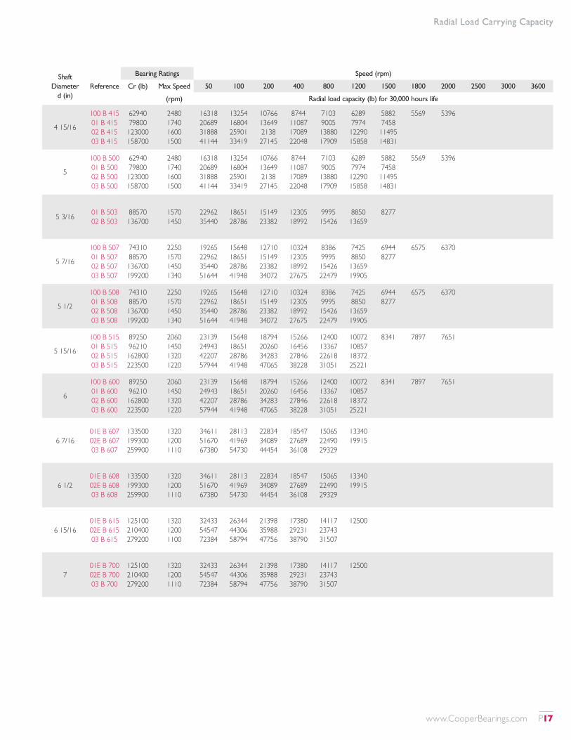
Radial Load Carrying Capacity
Shaft Diameter
d (in)Reference
Bearing Ratings Speed (rpm)
Cr (lb) Max Speed 50 100 200 400 800 1200 1500 1800 2000 2500 3000 3600
(rpm) Radial load capacity (lb) for 30,000 hours life
7 15/1601E B 715 02E B 715 03 B 715
152600 255500 326200
1320 1200 1110
39562 66240 84569
32135 53803 68691
26101 43702 55795
21201 35497 45319
17221 28832 36811
801E B 800 02E B 800 03 B 800
152600 255500 326200
1320 1200 1110
39562 66240 84569
32135 53803 68691
26101 43702 55795
21201 35497 45319
17221 28832 36811
901E B 900 02E B 900 03 B 900
160600 277300 356500
1320 1200 1110
41636 71891 92424
33819 58394 75072
27470 47431 60977
22312 38526 49529
18123 31293
1001E B 1000 02E B 1000 03 B 1000
180700 302600 399700
1320 1200 1110
46847 78451 103624
38052 63722 84169
30908 51758 68367
25105 42041 55531
20392
11
01E B 1100 02E B 1100 03X B 1100 03E B 1100
206100 347300 439700 473200
1320 1200 1110 1110
53432 90039 113994 122679
43401 73135 92592 99647
35252 59404 75208 80938
28634 48251 61088 65742
1201E B 1200 02E B 1200 03 B 1200
234000 373100 484700
1320 1200 1110
60666 96728 125661
49276 78568 102068
40024 63817 82905
32510 51835 67340
1301 B 1300 02 B 1300 03 B 1300
201000 352900 568500
590 550 500
52110 91491 147387
42327 74314 119715
34380 60362 97239
27925 49029 78982
1401 B 1400 02 B 1400 03E B 1400
210200 392100 618200
540 500 460
54495 101654 130271
44264 82569 130181
35954 67067 105740
29203 54475 85887
1501 B 1500 02 B 1500 03 B 1500
225900 418600 678700
500 460 420
58566 108524 175956
47570 88149 142921
38639 71599 116088
31385 58157 94293
16 01 B 1600 02 B 1600
235600 437900
460 430
61080 113528
49613 92213
40298 74900
32732 60830
1701 B 1700 02 B 1700 03E B 1700
244800 465100 781000
430 400 360
63466 120580 202478
51550 97941 164463
41872 79553 133586
34010 62617
1801 B 1800 02 B 1800 03E B 1800
253800 493400 820500
410 380 340
65799 127916 212719
53445 103900 172781
43411 84393 140342
35261
P18 www.CooperBearings.com
Radial Load Carrying Capacity
Shaft Diameter
d (in)Reference
Bearing Ratings Speed (rpm)
Cr (lb) Max Speed 50 100 200 400 800 1200 1500 1800 2000 2500 3000 3600
(rpm) Radial load capacity (lb) for 30,000 hours life
19 01 B 1900 02 B 1900
262800 520000
380 360
68132 134813
55341 109502
44951 88943
2001 B 2000 02 B 2000 03 B 2000
272300 546300 918800
360 340 310
70595 141631 238204
57341 115040 193481
46575 93442 157156
21 01 B 2100 02 B 2100
281700 597500
340 330
73032 154905
59321 125822
48183 102199
2201 B 2200 02 B 2200 03E B 2200
290900 627200 1050000
330 310 280
75417 162605 272218
61258 132076 221110
49757 107279 1795597
2301 B 2300 02 B 2300 03E B 2300
311800 525100 1099000
310 300 270
80836 136135 284921
65659 110576 231428
53332 89815 187978
24 01 B 2400 02 B 2400
321700 653000
300 290
83402 169294
67744 137509
55025 111692
www.CooperBearings.com P19
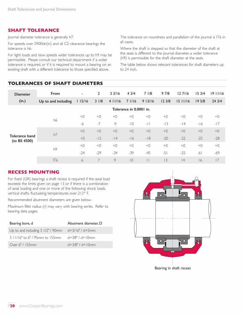
Shaft Tolerances and Journal Dimensions
SHAFT TOLERANCEJournal diameter tolerance is generally h7.For speeds over 5900dn(in) and all C2 clearance bearings the tolerance is h6.For light loads and slow speeds wider tolerances up to h9 may be permissible. Please consult our technical department if a wider tolerance is required, or if it is required to mount a bearing on an existing shaft with a different tolerance to those specified above.
The tolerance on roundness and parallelism of the journal is IT6 in all cases.Where the shaft is stepped so that the diameter of the shaft at the seals is different to the journal diameter, a wider tolerance (h9) is permissible for the shaft diameter at the seals.The table below shows relevant tolerances for shaft diameters up to 24 inch.
Diameter
(in.)
From - 2 3 3/16 4 3/4 7 1/8 9 7/8 12 7/16 15 3/4 19 11/16
Up to and including 1 15/16 3 1/8 4 11/16 7 1/16 9 13/16 12 3/8 15 11/16 19 5/8 24 3/4
Tolerance in 0.0001 in.
Tolerance band (to BS 4500)
h6+0 +0 +0 +0 +0 +0 +0 +0 +0
-6 -7 -9 -10 -11 -13 -14 -16 -17
h7+0 +0 +0 +0 +0 +0 +0 +0 +0
-10 -12 -14 -16 -18 -20 -22 -25 -28
h9+0 +0 +0 +0 +0 +0 +0 +0 +0
-24 -29 -34 -39 -45 -51 -55 -61 -69
IT6 6 7 9 10 11 13 14 16 17
TOLERANCES OF SHAFT DIAMETERS
RECESS MOUNTINGFor fixed (GR) bearings a shaft recess is required if the axial load exceeds the limits given on page 13 or if there is a combination of axial loading and one or more of the following: shock loads, vertical shafts, fluctuating temperatures over 212° F.Recommended abutment diameters are given below.Maximum fillet radius (r) may vary with bearing series. Refer to bearing data pages.
Bearing in shaft recess
Bearing bore, d Abutment diameter, D
Up to and including 3 1/2" / 90mm d+3/16" / d+5mm
3 11/16" to 6" / 95mm to 155mm d+3⁄8" / d+10mm
Over 6" / 155mm d+3/8" / d+10mm
P20 www.CooperBearings.com
Shaft Tolerances and Journal Dimensions
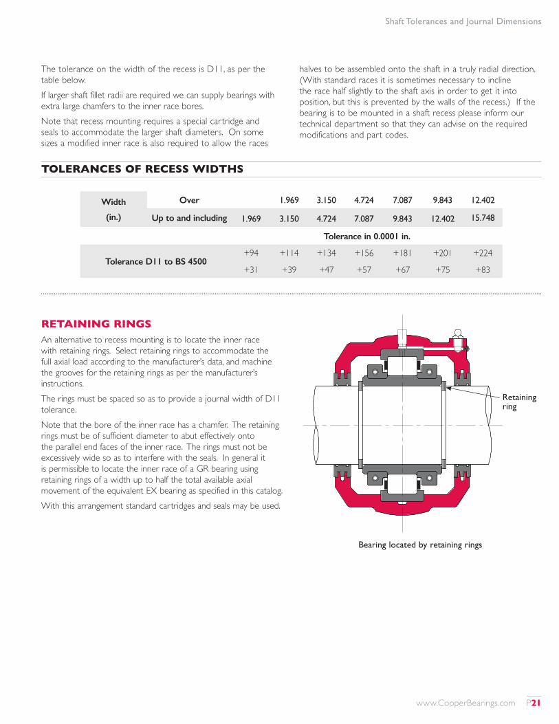
Width
(in.)
Over 1.969 3.150 4.724 7.087 9.843 12.402
Up to and including 1.969 3.150 4.724 7.087 9.843 12.402 15.748
Tolerance in 0.0001 in.
Tolerance D11 to BS 4500+94 +114 +134 +156 +181 +201 +224
+31 +39 +47 +57 +67 +75 +83
RETAINING RINGSAn alternative to recess mounting is to locate the inner race with retaining rings. Select retaining rings to accommodate the full axial load according to the manufacturer’s data, and machine the grooves for the retaining rings as per the manufacturer’s instructions.The rings must be spaced so as to provide a journal width of D11 tolerance.Note that the bore of the inner race has a chamfer. The retaining rings must be of sufficient diameter to abut effectively onto the parallel end faces of the inner race. The rings must not be excessively wide so as to interfere with the seals. In general it is permissible to locate the inner race of a GR bearing using retaining rings of a width up to half the total available axial movement of the equivalent EX bearing as specified in this catalog.With this arrangement standard cartridges and seals may be used.
Bearing located by retaining rings
Retaining ring
The tolerance on the width of the recess is D11, as per the table below.If larger shaft fillet radii are required we can supply bearings with extra large chamfers to the inner race bores.Note that recess mounting requires a special cartridge and seals to accommodate the larger shaft diameters. On some sizes a modified inner race is also required to allow the races
halves to be assembled onto the shaft in a truly radial direction. (With standard races it is sometimes necessary to incline the race half slightly to the shaft axis in order to get it into position, but this is prevented by the walls of the recess.) If the bearing is to be mounted in a shaft recess please inform our technical department so that they can advise on the required modifications and part codes.
TOLERANCES OF RECESS WIDTHS
www.CooperBearings.com P21
Vibration Data
Shaft Dia. d
Bearing Reference
Part Frequencies (per shaft rev.) Roller Details
Cage Roller Outer InnerPCD (in)
No.Dia. (in)
1 3/16 01 B 103 0.405 2.538 4.051 5.949 2.469 10 0.469
1 1/4 1 B 104 0.405 2.538 4.051 5.949 2.469 10 0.469
1 7/16 1 B 107 0.405 2.538 4.051 5.949 2.469 10 0.469
1 1/2 1 B 108 0.405 2.538 4.051 5.949 2.469 10 0.469
1 11/16 01E B 111 0.415 2.857 4.980 7.020 3.012 12 0.512
1 3/4 01E B 112 0.415 2.857 4.980 7.020 3.012 12 0.512
1 15/16 01E B 115 02 B 115
0.415 0.402
2.857 2.452
4.980 4.020
7.020 5.980
3.012 3.188
12 10
0.512 0.625
2 01E B 200 02 B 200
0.415 0.402
2.857 2.452
4.980 4.020
7.020 5.980
3.012 3.188
12 10
0.512 0.625
2 3/16 01E B 203 02 B 203
0.417 0.411
2.934 2.730
5.840 4.936
8.160 7.064
3.563 3.875
14 12
0.591 0.687
2 1/4 01E B 204 02 B 204
0.417 0.411
2.934 2.730
5.840 4.936
8.160 7.064
3.563 3.875
14 12
0.591 0.687
2 7/16 01E B 207 02 B 207
0.417 0.411
2.934 2.730
5.840 4.936
8.160 7.064
3.563 3.875
14 12
0.591 0.687
2 1/2 01E B 208 02 B 208
0.417 0.411
2.934 2.730
5.840 4.936
8.160 7.064
3.563 3.875
14 12
0.591 0.687
2 11/16 01E B 211 02 B 211
0.420 0.411
3.053 2.719
5.883 4.932
8.117 7.068
4.193 4.563
14 12
0.669 0.812
2 3/4 01E B 212 02 B 212
0.420 0.411
3.053 2.719
5.883 4.932
8.117 7.068
4.193 4.563
14 12
0.669 0.812
2 15/16100 B 215 01E B 215 02 B 215
0.448 0.420 0.411
4.723 3.053 2.719
8.953 5.883 4.932
11.047 8.117 7.068
3.760 4.193 4.563
20 14 12
0.394 0.669 0.812
3100 B 300 01E B 300 2 B 300
0.448 0.420 0.411
4.723 3.053 2.719
8.953 5.883 4.932
11.047 8.117 7.068
3.760 4.193 4.563
20 14 12
0.394 0.669 0.812
3 3/16 01E B 303 02 B 303
0.423 0.417
3.187 2.917
6.774 5.833
9.226 8.167
4.882 5.250
16 14
0.748 0.875
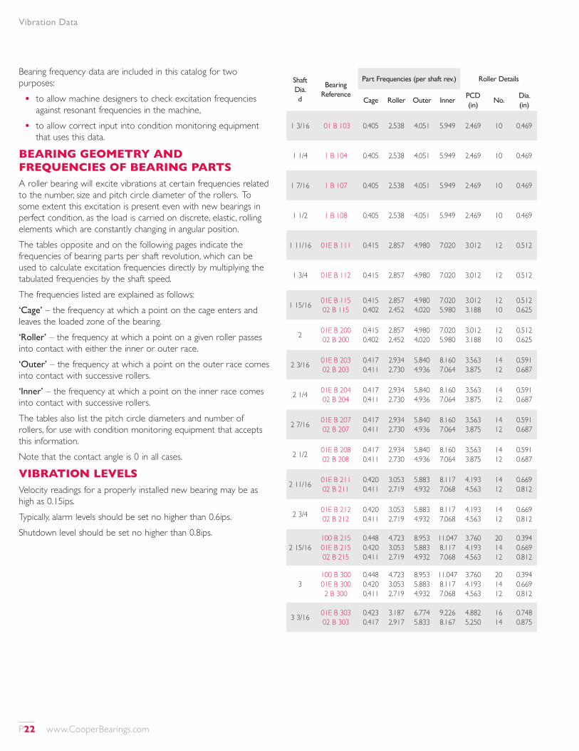
Bearing frequency data are included in this catalog for two purposes:
• to allow machine designers to check excitation frequencies against resonant frequencies in the machine,
• to allow correct input into condition monitoring equipment that uses this data.
BEARING GEOMETRY AND FREQUENCIES OF BEARING PARTSA roller bearing will excite vibrations at certain frequencies related to the number, size and pitch circle diameter of the rollers. To some extent this excitation is present even with new bearings in perfect condition, as the load is carried on discrete, elastic, rolling elements which are constantly changing in angular position.The tables opposite and on the following pages indicate the frequencies of bearing parts per shaft revolution, which can be used to calculate excitation frequencies directly by multiplying the tabulated frequencies by the shaft speed.The frequencies listed are explained as follows:‘Cage’ – the frequency at which a point on the cage enters and leaves the loaded zone of the bearing.‘Roller’ – the frequency at which a point on a given roller passes into contact with either the inner or outer race.‘Outer’ – the frequency at which a point on the outer race comes into contact with successive rollers.‘Inner’ – the frequency at which a point on the inner race comes into contact with successive rollers.The tables also list the pitch circle diameters and number of rollers, for use with condition monitoring equipment that accepts this information.Note that the contact angle is 0 in all cases.
VIBRATION LEVELSVelocity readings for a properly installed new bearing may be as high as 0.15ips.Typically, alarm levels should be set no higher than 0.6ips.Shutdown level should be set no higher than 0.8ips.
P22 www.CooperBearings.com
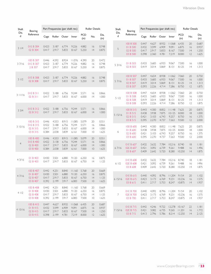
Vibration Data
Shaft Dia. d
Bearing Reference
Part Frequencies (per shaft rev.) Roller Details
Cage Roller Outer InnerPCD (in)
No.Dia. (in)
3 1/4 01E B 304 02 B 304
0.423 0.417
3.187 2.917
6.774 5.833
9.226 8.167
4.882 5.250
16 14
0.748 0.875
3 7/16100 B 307 01E B 307 2 B 307
0.446 0.423 0.417
4.592 3.187 2.917
8.924 6.774 5.833
11.076 9.226 8.167
4.390 4.882 5.250
20 16 14
0.472 0.748 0.875
3 1/2 01E B 308 02 B 308
0.423 0.417
3.187 2.917
6.774 5.833
9.226 8.167
4.882 5.250
16 14
0.748 0.875
3 11/16 01E B 311 02 B 311
0.422 0.417
3.188 2.917
6.756 5.833
9.244 8.167
5.571 6.000
16 14
0.866 1.000
3 3/4 01E B 312 02 B 312
0.422 0.417
3.188 2.917
6.756 5.833
9.244 8.167
5.571 6.000
16 14
0.866 1.000
3 15/16
100 B 315 01E B 315 02 B 315 03 B 315
0.446 0.422 0.417 0.384
4.553 3.188 2.917 2.038
8.915 6.756 5.833 3.839
11.085 9.244 8.167 6.161
5.079 5.571 6.000 7.000
20 16 14 10
0.551 0.866 1.000 1.625
4
100 B 400 01E B 400 02 B 400 03 B 400
0.446 0.422 0.417 0.384
4.553 3.138 2.917 2.038
8.915 6.756 5.833 3.839
11.085 9.244 8.167 6.161
5.079 5.571 6.000 7.000
20 16 14 10
0.551 0.866 1.000 1.625
4 3/16 01 B 403 02 B 403
0.430 0.417
3.501 2.917
6.880 5.833
9.120 8.167
6.250 6.750
16 14
0.875 1.125
4 7/16
100 B 407 01 B 407 02 B 407 03 B 407
0.442 0.430 0.417 0.392
4.251 3.501 2.917 2.199
8.840 6.880 5.833 3.917
11.160 9.120 8.167 6.083
5.768 6.250 6.750 7.500
20 16 14 10
0.669 0.875 1.125 1.625
4 1/2
100 B 408 01 B 408 02 B 408 03 B 408
0.442 0.430 0.417 0.392
4.251 3.501 2.917 2.199
8.840 6.880 5.833 3.917
11.160 9.120 8.167 6.083
5.768 6.250 6.750 7.500
20 16 14 10
0.669 0.875 1.125 1.625
4 15/16
100 B 415 01 B 415 02 B 415 03 B 415
0.447 0.432 0.417 0.398
4.627 3.599 2.917 2.199
8.932 6.909 5.833 4.781
11.068 9.091 8.167 7.219
6.435 6.875 7.500 8.000
20 16 14 12
0.687 0.937 1.250 1.625
Shaft Dia. d
Bearing Reference
Part Frequencies (per shaft rev.) Roller Details
Cage Roller Outer InnerPCD (in)
No.Dia. (in)
5
100 B 500 01 B 500 02 B 500 03 B 500
0.447 0.432 0.417 0.398
4.627 3.599 2.917 2.360
8.932 6.909 5.833 4.781
11.068 9.091 8.167 7.219
6.435 6.875 7.500 8.000
20 16 14 12
0.687 0.937 1.250 1.625
5 3/16 01 B 503 02 B 503
0.433 0.419
3.683 3.014
6.933 5.869
9.067 8.131
7.500 8.125
16 14
1.000 1.313
5 7/16
100 B 507 01 B 507 02 B 507 03 B 507
0.447 0.433 0.419 0.393
4.654 3.683 3.014 2.226
8.938 6.933 5.869 4.714
11.062 9.067 8.131 7.286
7.060 7.500 8.125 8.750
20 16 14 12
0.750 1.000 1.313 1.875
5 1/2
100 B 508 01 B 508 02 B 508 03 B 508
0.447 0.433 0.419 0.393
4.654 3.683 3.014 2.226
8.938 6.933 5.869 4.714
11.062 9.067 8.131 7.286
7.060 7.500 8.125 8.750
20 16 14 12
0.750 1.000 1.313 1.875
5 15/16
100 B 515 01 B 515 02 B 515 03 B 515
0.443 0.438 0.421 0.395
4.300 3.938 3.103 2.270
8.852 7.875 6.743 4.737
11.148 10.125 9.257 7.263
7.625 8.000 8.750 9.500
20 18 16 12
0.875 1.000 1.375 2.000
6
100 B 600 01 B 600 02 B 600 03 B 600
0.443 0.438 0.421 0.395
4.300 3.938 3.103 2.270
8.852 7.875 6.743 4.737
11.148 10.125 9.257 7.263
7.625 8.000 8.750 9.500
20 18 16 12
0.875 1.000 1.375 2.000
6 7/1601E B 607 02E B 607 03 B 607
0.432 0.421 0.409
3.632 3.092 2.642
7.784 6.739 5.720
10.216 9.261 8.280
8.740 9.488 10.250
18 16 14
1.181 1.496 1.875
6 1/201E B 608 02E B 608 03 B 608
0.432 0.421 0.409
3.632 3.092 2.642
7.784 6.739 5.720
10.216 9.261 8.280
8.740 9.488 10.250
18 16 14
1.181 1496 1.875
6 15/1601E B 615 02E B 615 03 B 615
0.440 0.423 0.411
4.092 3.173 2.717
8.796 6.769 5.753
11.204 9.231 8.247
9.154 10.236 10.875
20 16 14
1.102 1.575 1.937
701E B 700 02E B 700 03 B 700
0.440 0.423 0.411
4.092 3.173 2.717
8.796 6.769 5.753
11.204 9.231 8.247
9.154 10.236 10.875
20 16 14
1.102 1.575 1.937
7 15/1601E B 715 02E B 715 03 B 715
0.442 0.421 0.413
4.246 3.082 2.796
9.722 6.735 5.786
12.278 9.265 8.214
10.167 11.201 12.250
22 16 14
1.181 1.772 2.125
www.CooperBearings.com P23
Shaft Dia. d
Bearing Reference
Part Frequencies (per shaft rev.) Roller Details
Cage Roller Outer InnerPCD (in)
No.Dia. (in)
801E B 800 02E B 800 03 B 800
0.442 0.421 0.413
4.246 3.062 2.796
9.722 6.735 5.786
12.278 9.265 8.214
10.167 11.201 12.250
22 16 14
1.181 1.772 2.125
901E B 900 02E B 900 03 B 900
0.448 0.428 0.414
4.727 3.423 2.808
10.745 7.712 4.964
13.255 10.288 7.036
11.289 12.382 13.750
24 18 12
1.181 1.772 2.375
1001E B 1000 02E B 1000 03 B 1000
0.450 0.427 0.418
4.911 3.367 2.971
11.690 6.837 5.853
14.310 9.163 8.147
12.500 13.543 14.500
22 16 14
1.260 1.969 2.375
11
01E B 1100 02E B 1100 03X B 1100 03E B 1100
0.449 0.433 0.425 0.423
4.856 3.668 3.240 3.160
11.675 7.795 6.794 6.764
14.325 10.205 9.206 9.236
13.524 14.705 15.750 15.375
26 18 16 16
1.378 1.969 2.375 2.375
1201E B 1200 02E B 1200 03 B 1200
0.453 0.438 0.426
5.246 3.953 3.326
12.677 8.755 6.824
15.323 11.245 9.176
14.587 15.807 17.000
28 20 16
1.378 1.969 2.500
1301 B 1300 02 B 1300 03 B 1300
0.458 0.443 0.423
5.910 4.297 3.184
11.908 8.852 5.927
14.092 11.148 8.073
15.625 16.875 18.748
26 20 14
1.312 1.937 2.875
1401 B 340M 02 B 340M 03E B 340M
0.461 0.443 0.428
6.294 4.337 3.405
12.895 8.862 6.850
15.105 11.138 9.150
16.625 18.125 19.125
28 20 16
1.312 2.063 2.750
1501 B 1500 02 B 1500 03 B 1500
0.461 0.446 0.429
6.416 4.552 3.429
12.915 9.806 6.857
15.085 12.194 9.143
17.750 19.000 21.000
28 22 16
1.375 2.063 3.000
1601 B 1600 02 B 1600 03 B 1600
0.463 0.447 0.429
6.782 4.682 3.429
13.900 9.839 6.857
16.100 12.161 9.143
18.750 20.125 21.000
30 22 16
1.375 2.125 3.000
Shaft Dia. d
Bearing Reference
Part Frequencies (per shaft rev.) Roller Details
Cage Roller Outer InnerPCD (in)
No.Dia. (in)
1701 B 1700 02 B 1700 03E B 1700
0.465 0.449 0.435
7.147 4.806 3.759
14.886 9.868 8.693
17.114 12.132 11.307
19.750 21.250 22.283
32 22 20
1.375 2.188 2.913
18
01 B 1800 02 B 1800 03E B 1800 03X B 1800
0.467 0.451 0.433 0.432
7.512 5.008 3.683 3.598
15.873 10.814 7.800 6.909
18.127 13.186 10.200 9.091
20.750 22.125 23.622 24.750
34 24 18 16
1.375 2.188 3.150 3.375
19 01 B 1900 02 B 1900
0.467 0.453
7.576 5.267
14.949 11.777
17.051 14.223
21.875 23.250
32 26
1.437 2.188
2001 B 2000 02 B 2000 03 B 2000
0.469 0.455 0.437
7.925 5.469 3.900
15.932 12.731 7.864
18.068 15.269 10.136
22.875 24.125 26.750
34 28 18
1.437 2.188 3.375
21 01 B 2100 02 B 2100
0.470 0.453
8.362 5.322
16.927 11.789
19.073 14.211
24.125 25.500
36 26
1.437 2.375
2201 B 2200 02 B 2200 03E B 2200
0.471 0.455 0.440
8.711 5.561 4.107
17.913 12.751 8.800
20.087 15.249 11.200
25.125 26.625 28.125
38 28 20
1.437 2.375 3.375
2301 B 2300 02 B 2300 03E B 2300
0.471 0.461 0.442
8.721 6.432 4.244
17.914 13.841 9.722
20.086 16.159 12.278
26.250 27.500 29.134
38 30 22
1.500 2.125 3.386
24 01 B 2400 02 B 2400
0.472 0.458
9.056 5.958
18.899 13.750
21.101 16.250
27.250 28.500
40 30
1.500 2.375
Vibration Data
P24 www.CooperBearings.com
Sealing Solutions
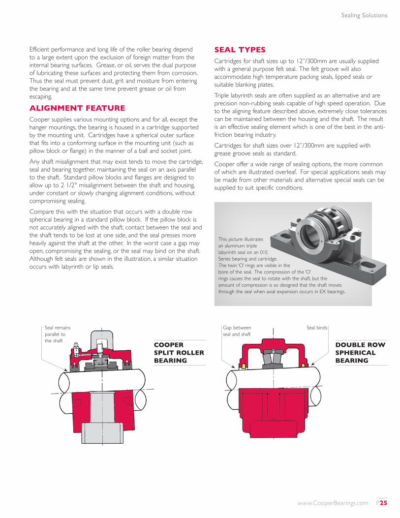
Efficient performance and long life of the roller bearing depend to a large extent upon the exclusion of foreign matter from the internal bearing surfaces. Grease, or oil, serves the dual purpose of lubricating these surfaces and protecting them from corrosion. Thus the seal must prevent dust, grit and moisture from entering the bearing and at the same time prevent grease or oil from escaping.
ALIGNMENT FEATURECooper supplies various mounting options and for all, except the hanger mountings, the bearing is housed in a cartridge supported by the mounting unit. Cartridges have a spherical outer surface that fits into a conforming surface in the mounting unit (such as pillow block or flange) in the manner of a ball and socket joint.Any shaft misalignment that may exist tends to move the cartridge, seal and bearing together, maintaining the seal on an axis parallel to the shaft. Standard pillow blocks and flanges are designed to allow up to 2 1/2° misalignment between the shaft and housing, under constant or slowly changing alignment conditions, without compromising sealing.Compare this with the situation that occurs with a double row spherical bearing in a standard pillow block. If the pillow block is not accurately aligned with the shaft, contact between the seal and the shaft tends to be lost at one side, and the seal presses more heavily against the shaft at the other. In the worst case a gap may open, compromising the sealing, or the seal may bind on the shaft. Although felt seals are shown in the illustration, a similar situation occurs with labyrinth or lip seals.
SEAL TYPESCartridges for shaft sizes up to 12”/300mm are usually supplied with a general purpose felt seal. The felt groove will also accommodate high temperature packing seals, lipped seals or suitable blanking plates.Triple labyrinth seals are often supplied as an alternative and are precision non-rubbing seals capable of high speed operation. Due to the aligning feature described above, extremely close tolerances can be maintained between the housing and the shaft. The result is an effective sealing element which is one of the best in the anti-friction bearing industry.Cartridges for shaft sizes over 12”/300mm are supplied with grease groove seals as standard.Cooper offer a wide range of sealing options, the more common of which are illustrated overleaf. For special applications seals may be made from other materials and alternative special seals can be supplied to suit specific conditions.
This picture illustrates an aluminum triple labyrinth seal on an 01E Series bearing and cartridge. The twin ‘O’ rings are visible in the bore of the seal. The compression of the ‘O’ rings causes the seal to rotate with the shaft, but the amount of compression is so designed that the shaft moves through the seal when axial expansion occurs in EX bearings.
Gap between seal and shaft
Seal binds
DOUBLE ROW SPHERICAL BEARING
Seal remains parallel to the shaft
COOPER SPLIT ROLLER BEARING
www.CooperBearings.com P25
Sealing Solutions
GREASE GROOVE (LAB)
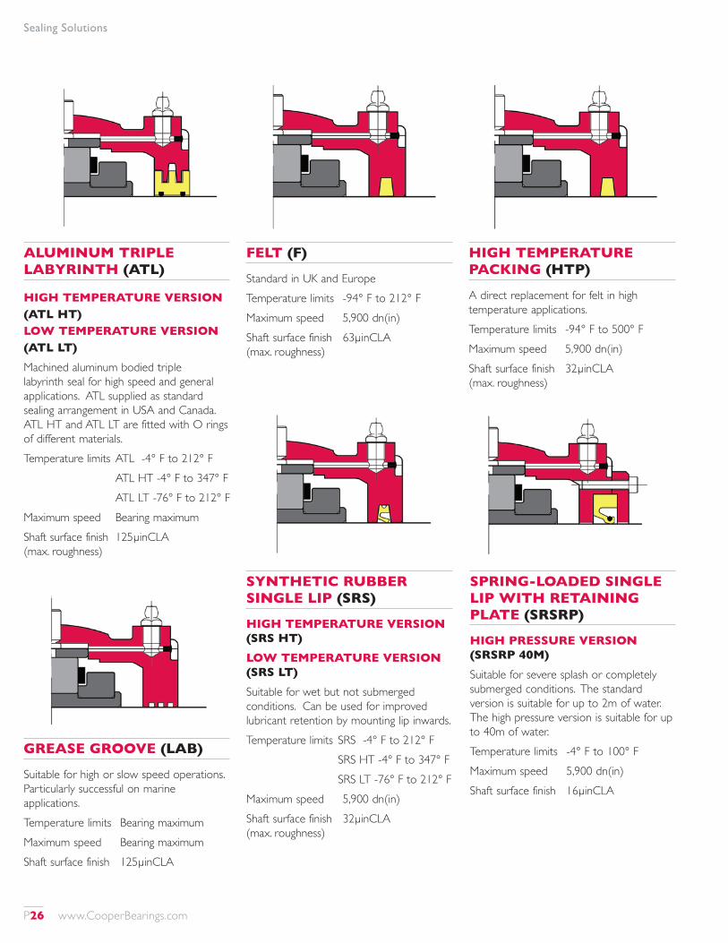
Suitable for high or slow speed operations. Particularly successful on marine applications.Temperature limits Bearing maximumMaximum speed Bearing maximumShaft surface finish 125µinCLA
FELT (F)
Standard in UK and EuropeTemperature limits -94° F to 212° FMaximum speed 5,900 dn(in)Shaft surface finish 63µinCLA (max. roughness)
HIGH TEMPERATURE PACKING (HTP)
A direct replacement for felt in high temperature applications.Temperature limits -94° F to 500° FMaximum speed 5,900 dn(in)Shaft surface finish 32µinCLA (max. roughness)
ALUMINUM TRIPLE LABYRINTH (ATL)
HIGH TEMPERATURE VERSION (ATL HT) LOW TEMPERATURE VERSION (ATL LT)Machined aluminum bodied triple labyrinth seal for high speed and general applications. ATL supplied as standard sealing arrangement in USA and Canada. ATL HT and ATL LT are fitted with O rings of different materials.Temperature limits ATL -4° F to 212° F ATL HT -4° F to 347° F ATL LT -76° F to 212° FMaximum speed Bearing maximumShaft surface finish 125µinCLA (max. roughness)
SYNTHETIC RUBBER SINGLE LIP (SRS)
HIGH TEMPERATURE VERSION (SRS HT)LOW TEMPERATURE VERSION (SRS LT)Suitable for wet but not submerged conditions. Can be used for improved lubricant retention by mounting lip inwards.Temperature limits SRS -4° F to 212° F SRS HT -4° F to 347° F SRS LT -76° F to 212° FMaximum speed 5,900 dn(in)Shaft surface finish 32µinCLA (max. roughness)
SPRING-LOADED SINGLE LIP WITH RETAINING PLATE (SRSRP)
HIGH PRESSURE VERSION (SRSRP 40M)Suitable for severe splash or completely submerged conditions. The standard version is suitable for up to 2m of water. The high pressure version is suitable for up to 40m of water.Temperature limits -4° F to 100° FMaximum speed 5,900 dn(in)Shaft surface finish 16µinCLA
P26 www.CooperBearings.com
Sealing Solutions
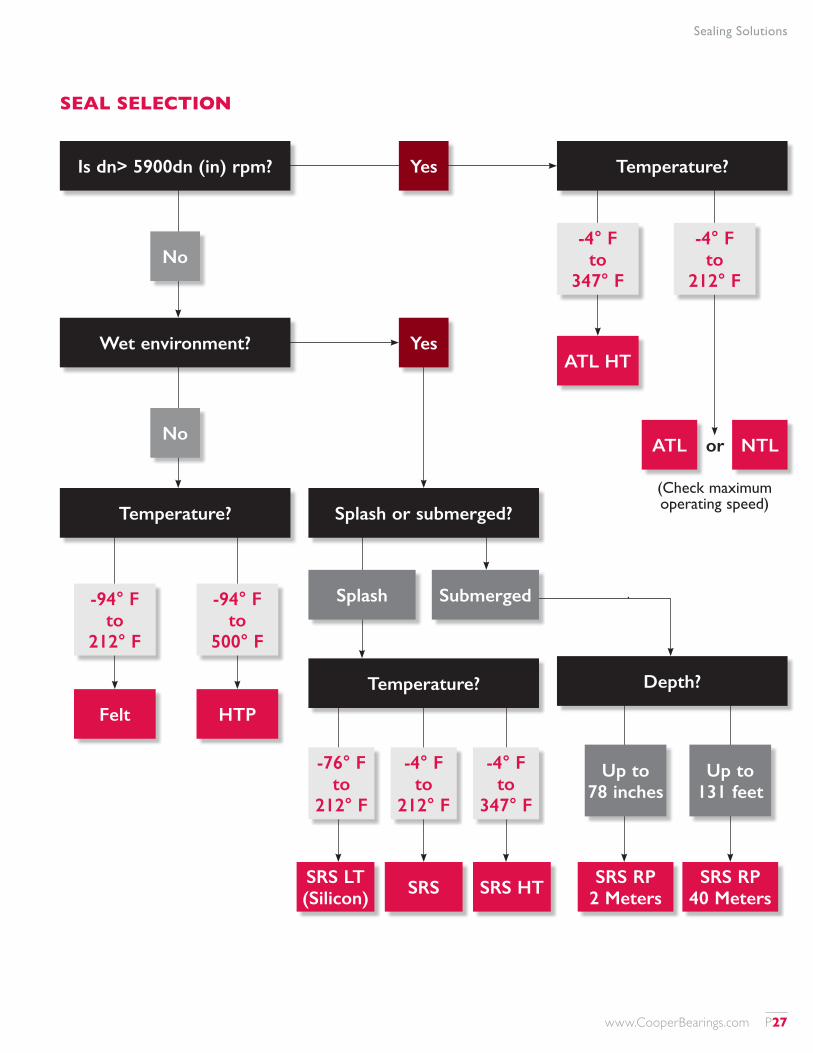
SEAL SELECTION
or
(Check maximum operating speed)
Is dn> 5900dn (in) rpm?
Splash or submerged?
Depth?
No
No
Wet environment?
Temperature?
Temperature?
-76° F to
212° F
SRS LT (Silicon)
-4° F to
347° F
SRS HT
-4° F to
212° F
SRS
-94° F to
212° F
Splash Submerged
-4° F to
347° F
Felt
ATL
Up to 78 inches
SRS RP 2 Meters
ATL HT
-94° F to
500° F
-4° F to
212° F
HTP
NTL
Up to 131 feet
SRS RP 40 Meters
Yes
Yes
Temperature?
www.CooperBearings.com P27
Blanking Plates
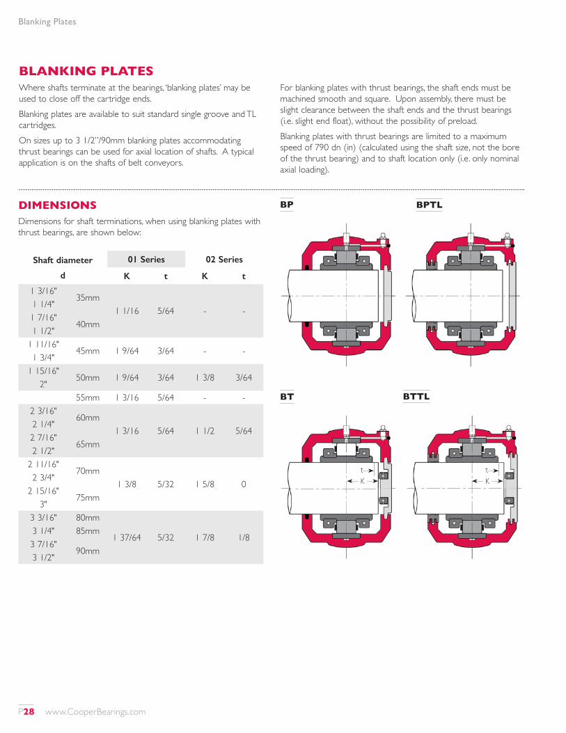
BLANKING PLATESWhere shafts terminate at the bearings, ‘blanking plates’ may be used to close off the cartridge ends.Blanking plates are available to suit standard single groove and TL cartridges.On sizes up to 3 1/2”/90mm blanking plates accommodating thrust bearings can be used for axial location of shafts. A typical application is on the shafts of belt conveyors.
For blanking plates with thrust bearings, the shaft ends must be machined smooth and square. Upon assembly, there must be slight clearance between the shaft ends and the thrust bearings (i.e. slight end float), without the possibility of preload.Blanking plates with thrust bearings are limited to a maximum speed of 790 dn (in) (calculated using the shaft size, not the bore of the thrust bearing) and to shaft location only (i.e. only nominal axial loading).
BP BPTL
Shaft diameter
d
01 Series 02 Series
K t K t
1 3/16"35mm
1 1/16 5/64 - -1 1/4"1 7/16"
40mm1 1/2"
1 11/16"45mm 1 9/64 3/64 - -
1 3/4"1 15/16"
50mm 1 9/64 3/64 1 3/8 3/642"
55mm 1 3/16 5/64 - -2 3/16"
60mm1 3/16 5/64 1 1/2 5/64
2 1/4"2 7/16"
65mm2 1/2"
2 11/16"70mm
1 3/8 5/32 1 5/8 02 3/4"
2 15/16"75mm
3"3 3/16" 80mm
1 37/64 5/32 1 7/8 1/83 1/4" 85mm3 7/16"
90mm3 1/2"
DIMENSIONSDimensions for shaft terminations, when using blanking plates with thrust bearings, are shown below:
BTTLBT
Kt
Kt
P28 www.CooperBearings.com
Blanking Plates
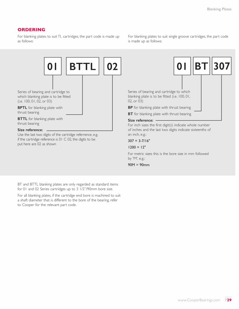
ORDERINGFor blanking plates to suit TL cartridges, the part code is made up as follows:
For blanking plates to suit single groove cartridges, the part code is made up as follows:
BT and BTTL blanking plates are only regarded as standard items for 01 and 02 Series cartridges up to 3 1/2”/90mm bore size.For all blanking plates, if the cartridge end bore is machined to suit a shaft diameter that is different to the bore of the bearing, refer to Cooper for the relevant part code.
Series of bearing and cartridge to which blanking plate is to be fitted (i.e. 100, 01, 02, or 03)BPTL for blanking plate with thrust bearingBTTL for blanking plate with thrust bearingSize reference: Use the last two digits of the cartridge referrence, e.g. if the cartridge reference is 01 C 02, the digits to be put here are 02 as shown
Series of bearing and cartridge to which blanking plate is to be fitted (i.e. 100, 01, 02, or 03)BP for blanking plate with thrust bearingBT for blanking plate with thrust bearingSize reference: For inch sizes the first digit(s) indicate whole number of inches and the last two digits indicate sixteenths of an inch, e.g.: 307 = 3-7/16"
1200 = 12"
For metric sizes this is the bore size in mm followed by 'M', e.g.:90M = 90mm
01 0102 307BTTL BT
www.CooperBearings.com P29
Lubrication
BEARING LUBRICATIONFriction and wear are reduced by separating rollers and races with a lubricant film to minimize metal to metal contact. The major factors in selecting a lubricant are speed, lubricant base oil, viscosity and temperature.As speed and viscosity increase, thickness of lubricant film increases. As temperature increases, lubricant film thickness decreases. The lubricant film should be sufficient to cover the average peaks on the bearing surface by a ratio of at least 1.25. As the ratio falls below 1.25, some metal to metal contact will occur with a corresponding loss of L10 life.This situation should not occur if the lubricant is selected according to the method given on page 31.
GREASE LUBRICATIONStandard cartridges are designed for grease lubrication. Lubrication points are tapped 1/8" NPT or 1/4" NPT depending on size, and fitted with grease nipples. Alternative tappings or fittings are available on request.Grease lubrication is easier to retain in the bearing than oil, offering lower lubricant losses and improved sealing. Grease also offers better protection against corrosion to the rolling surfaces.A grease typically consists of three components; a thickener (sometimes called a soap), a base oil and additives. The oil in the grease has an ISO-VG rating. In most cases, this is the key to selecting the grease. At speeds in excess of 7900 dn (in), greases with synthetic base oils are recommended. Please consult our technical department for proper grease selection.The National Lubricating Grease Institute (NLGI) has designated consistency grades for greases based upon the amount of thickener in the grease. The standard recommended grease for Cooper is a No.2 or No.3 consistency grade with an EP additive. The exception to this is a centrally pumped system where a No.1 is used for “pumpability”.
A lithium complex thickener is used for normal applications operating at temperatures between 32° F and 176° F. When water resistance is required, an aluminum complex thickener can be used. Aluminum complex greases are not compatible with some other types of grease. The bearing must therefore be solvent cleaned of other greases prior to adding an aluminum complex based grease.The initial pack of grease depends on speed. The initial pack should be used to coat the rolling surfaces of the bearing during installation. Further information is to be found on page 172.For extreme temperatures, speeds and loads always obtain a lubricant selection from our technical department.
OIL LUBRICATIONOil lubrication can be broken down into three major categories; recirculating oil systems, constant level and oil mist.Recirculating oil systems use a pump to provide a continuous flow of oil to the bearing which is then recaptured, cooled, filtered and recirculated.A constant level oiler is the simplest method for delivery of oil lubrication to a bearing. The oiler maintains a constant level in the bottom of the bearing. Ideal conditions for oiler use would be bearing temperature less than 140° F and downwards load with low to moderate speeds.An oil mist system uses compressed air to atomise oil and spray it into the bearing. Conveying oil with filtered air maintains a positive pressure in the cartridge which is an effective method for keeping out contaminants. Oil mist systems are especially effective for high speeds.If oil lubrication is required a modified cartridge is required. Please contact our technical department with details of lubrication system to be used.
dn (in) = bearing bore (in) x shaft speed (rpm)
P30 www.CooperBearings.com
Lubrication
SELECTION OF BASE OIL VISCOSITY (ISO-VG)Grease selected for bearing lubrication must have a base oil of sufficiently high viscosity to adequately separate the rolling elements and race parts under operating conditions, in order for the bearing to provide a long service life. The same comment applies for the viscosity of the oil if oil lubrication is used.The charts on page 33 show the recommended operating ranges for three common oil viscosities, for bearings under normal loading (for radial loads up to Cr/10).In order to use these charts, the ‘geometry factor’ for the bearing in question must be found, from the table opposite and on the following pages, and this geometry factor multiplied by the bearing speed (in thousands of rpm) in order to obtain the ‘velocity factor’.For example, if an 01E B 207 bearing is to be run at 1800rpm:
The geometry factor is 48.2 from the table. Velocity factor = 48.2 x 1800/1000 = 86.76
To determine the suitability of one of these oils, draw a vertical line from the horizontal axis at the calculated velocity factor, and draw a horizontal line from vertical axis at the operating temperature.If the lines intersect in the shaded area the viscosity of the oil is suitable.If the lines intersect above the shaded area a higher viscosity oil is required.If the lines intersect below the shaded area the bearing may operate satisfactorily, but it is suggested that a lower viscosity oil is used.The use of these charts is subject to the operating conditions being within the recommended ranges for the lubricant as specified by the lubricant manufacturer.For conditions not covered by these charts, please contact our technical department.Note that the lubricant film thickness is not particularly sensitive to load, so for heavier loading the lubricant selection as provided by these charts is usually sufficient provided that the lines drawn on the chart, as explained above, do not intersect at the upper edge of the shaded area.It is recommended that our technical department is contacted with details of the application if extremes of load, speed or temperature are expected.
Shaft Dia. d
Bearing Reference
Geometry Factor
1 3/16 01 B 103 27.3
1 1/4 1 B 104 27.3
1 7/16 1 B 107 27.3
1 1/2 1 B 108 27.3
1 11/16 01E B 111 37.6
1 3/4 01E B 112 37.6
1 15/16 01E B 115 02 B 115
37.6 39.0
2 01E B 200 02 B 200
37.6 39.0
2 3/16 01E B 203 02 B 203
48.2 53.2
2 1/4 01E B 204 02 B 204
48.2 53.2
2 7/16 01E B 207 02 B 207
48.2 53.2
2 1/2 01E B 208 02 B 208
48.2 53.2
2 11/16 01E B 211 02 B 211
61.4 67.1
2 3/4 01E B 212 02 B 212
61.4 67.1
2 15/16100 B 215 01E B 215 02 B 215
57.5 61.4 67.1
3100 B 300 01E B 300 2 B 300
57.5 61.4 67.1
Shaft Dia. d
Bearing Reference
Geometry Factor
3 3/16 01E B 303 02 B 303
77.2 83.7
3 1/4 01E B 304 02 B 304
77.2 83.7
3 7/16100 B 307 01E B 307 2 B 307
71.5 77.2 83.7
3 1/2 01E B 308 02 B 308
77.2 83.7
3 11/16 01E B 311 02 B 311
92.8 101
3 3/4 01E B 312 02 B 312
92.8 101
3 15/16
100 B 315 01E B 315 02 B 315 03 B 315
87.9 92.8 101 112
4
100 B 400 01E B 400 02 B 400 03 B 400
87.9 92.8 101 112
4 3/16 01 B 403 02 B 403
112 120
4 7/16
100 B 407 01 B 407 02 B 407 03 B 407
104 112 120 127
www.CooperBearings.com P31
Lubrication
Shaft Dia. d
Bearing Reference
Geometry Factor
4 1/2
100 B 408 01 B 408 02 B 408 03 B 408
104 112 120 127
4 15/16
100 B 415 01 B 415 02 B 415 03 B 415
124 129 139 143
5
100 B 500 01 B 500 02 B 500 03 B 500
124 129 139 143
5 3/16 01 B 503 02 B 503
147 158
5 7/16
100 B 507 01 B 507 02 B 507 03 B 507
141 147 158 160
5 1/2
100 B 508 01 B 508 02 B 508 03 B 508
141 147 158 160
5 15/16
100 B 515 01 B 515 02 B 515 03 B 515
155 164 176 181
6
100 B 600 01 B 600 02 B 600 03 B 600
155 164 176 181
Shaft Dia. d
Bearing Reference
Geometry Factor
11
01E B 1100 02E B 1100 03X B 1100 03E B 1100
360 385 413 397
1201E B 1200 02E B 1200 03 B 1200
406 434 463
1301 B 1300 02 B 1300 03 B 1300
455 484 527
1401 B 340M 02 B 340M 03E B 340M
501 536 551
1501 B 1500 02 B 1500 03 B 1500
551 579 631
1601 B 1600 02 B 1600 03 B 1600
600 631 631
1701 B 1700 02 B 1700 03E B 1700
650 685 701
Shaft Dia. d
Bearing Reference
Geometry Factor
6 7/1601E B 607 02E B 607 03 B 607
183 198 212
6 1/201E B 608 02E B 608 03 B 608
183 198 212
6 15/1601E B 615 02E B 615 03 B 615
200 222 232
701E B 700 02E B 700 03 B 700
200 222 232
7 15/1601E B 715 02E B 715 03 B 715
234 251 277
801E B 800 02E B 800 03 B 800
234 251 277
901E B 900 02E B 900 03 B 900
277 297 328
1001E B 1000 02E B 1000 03 B 1000
322 336 359
Shaft Dia. d
Bearing Reference
Geometry Factor
18
01 B 1800 02 B 1800 03E B 1800 03X B 1800
701 730 759 807
19 01 B 1900 02 B 1900
757 790
2001 B 2000 02 B 2000 03 B 2000
810 837 917
21 01 B 2100 02 B 2100
879 903
2201 B 2200 02 B 2200 03E B 2200
934 966 995
2301 B 2300 02 B 2300 03E B 2300
995 1031 1053
24 01 B 2400 02 B 2400
1053 1075
P32 www.CooperBearings.com
Lubrication
COOPER BEARING RECOMMENDED SPEED AND TEMPERATURE RANGE FOR ISO VG 150 GREASE AND OILS
COOPER BEARING RECOMMENDED SPEED AND TEMPERATURE RANGE FOR ISO VG 220 GREASE AND OILS
COOPER BEARING RECOMMENDED SPEED AND TEMPERATURE RANGE FOR ISO VG 460 GREASE AND OILS
280
260
240
220
200
180
160
140
120
100
80
60
40
20
0 0 20 40 60 80 100 120 140 160 180 200 220 240 260 280 300
Velocity factor = geometry factory X rpm in thousands
Tem
pera
ture
(F)
VG15
0
280
260
240
220
200
180
160
140
120
100
80
60
40
20
0 0 20 40 60 80 100 120 140 160 180 200 220 240 260 280 300
Velocity factor = geometry factory X rpm in thousands
Tem
pera
ture
(F)
VG22
0
280
260
240
220
200
180
160
140
120
100
80
60
40
20
0 0 20 40 60 80 100 120 140 160 180 200 220 240 260 280 300
Velocity factor = geometry factory X rpm in thousands
Tem
pera
ture
(F)
VG46
0
www.CooperBearings.com P33
Standard Bearings, Cartridges And Pillow Blocks To 24"/600mm Bore Size
BEARINGSThe following pages list standard bearings of Series 100, 01, 02 and 03, alongside compatible standard cartridges and pillow blocks. Principles of bearing selection are explained on pages 11 to 13.Large bore bearings and 04 Series bearings are listed separately elsewhere in this catalog.
CARTRIDGES AND SEALSMost Cooper split roller bearings are mounted in a ‘cartridge’. This is a spherically-machined inner housing that can be fitted into a number of outer housings including pedestals, flanges, rod-ends, take-up units and custom housings either supplied by Cooper or manufactured by the customer.The cartridge houses the bearing and seals. For any given size of bearing there are two main types of cartridge. The standard cartridge in the US and Canada, is the ‘triple labyrinth’ (TL) type, which accommodates either an aluminum triple labyrinth (ATL) seal or, on some sizes only, a neoprene triple labyrinth (NTL).
Outside the US and Canada, but readily available in the US and Canada, the standard cartridge up to 12”/300mm shaft size features a groove in each end bore that can accommodate a felt seal (supplied as standard with the cartridge), high temperature packing, or a rubber lipped seal. The standard cartridge for shaft sizes over 12”/300mm outside the US and Canada features groove grease seals.Cartridges to accommodate other types of seal, such as lip seals for submerged conditions, and combinations of seals, may require special machining and may have a different length on shaft to the standard types listed.Cartridges for expansion (EX) and fixed (GR) bearings differ, so care must be taken to order the correct version and ensure that EX and GR bearings are fitted in the correct cartridges during assembly. Cartridges for GR bearings feature drillings for ‘side screws’ that locate the outer race against one side of the seating, while cartridges for EX bearings may include additional internal machining.
P34 www.CooperBearings.com
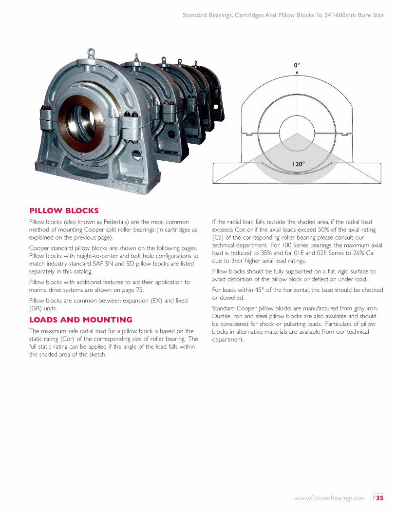
Standard Bearings, Cartridges And Pillow Blocks To 24"/600mm Bore Size
PILLOW BLOCKSPillow blocks (also known as Pedestals) are the most common method of mounting Cooper split roller bearings (in cartridges as explained on the previous page).Cooper standard pillow blocks are shown on the following pages. Pillow blocks with height-to-center and bolt hole configurations to match industry standard SAF, SN and SD pillow blocks are listed separately in this catalog.Pillow blocks with additional features to aid their application to marine drive systems are shown on page 75.Pillow blocks are common between expansion (EX) and fixed (GR) units.
LOADS AND MOUNTINGThe maximum safe radial load for a pillow block is based on the static rating (Cor) of the corresponding size of roller bearing. The full static rating can be applied if the angle of the load falls within the shaded area of the sketch.
If the radial load falls outside the shaded area, if the radial load exceeds Cor, or if the axial loads exceed 50% of the axial rating (Ca) of the corresponding roller bearing please consult our technical department. For 100 Series bearings, the maximum axial load is reduced to 35% and for 01E and 02E Series to 26% Ca due to their higher axial load ratings.Pillow blocks should be fully supported on a flat, rigid surface to avoid distortion of the pillow block or deflection under load.For loads within 45° of the horizontal, the base should be chocked or dowelled.Standard Cooper pillow blocks are manufactured from gray iron. Ductile iron and steel pillow blocks are also available and should be considered for shock or pulsating loads. Particulars of pillow blocks in alternative materials are available from our technical department.
0°
120°
0°
www.CooperBearings.com P35
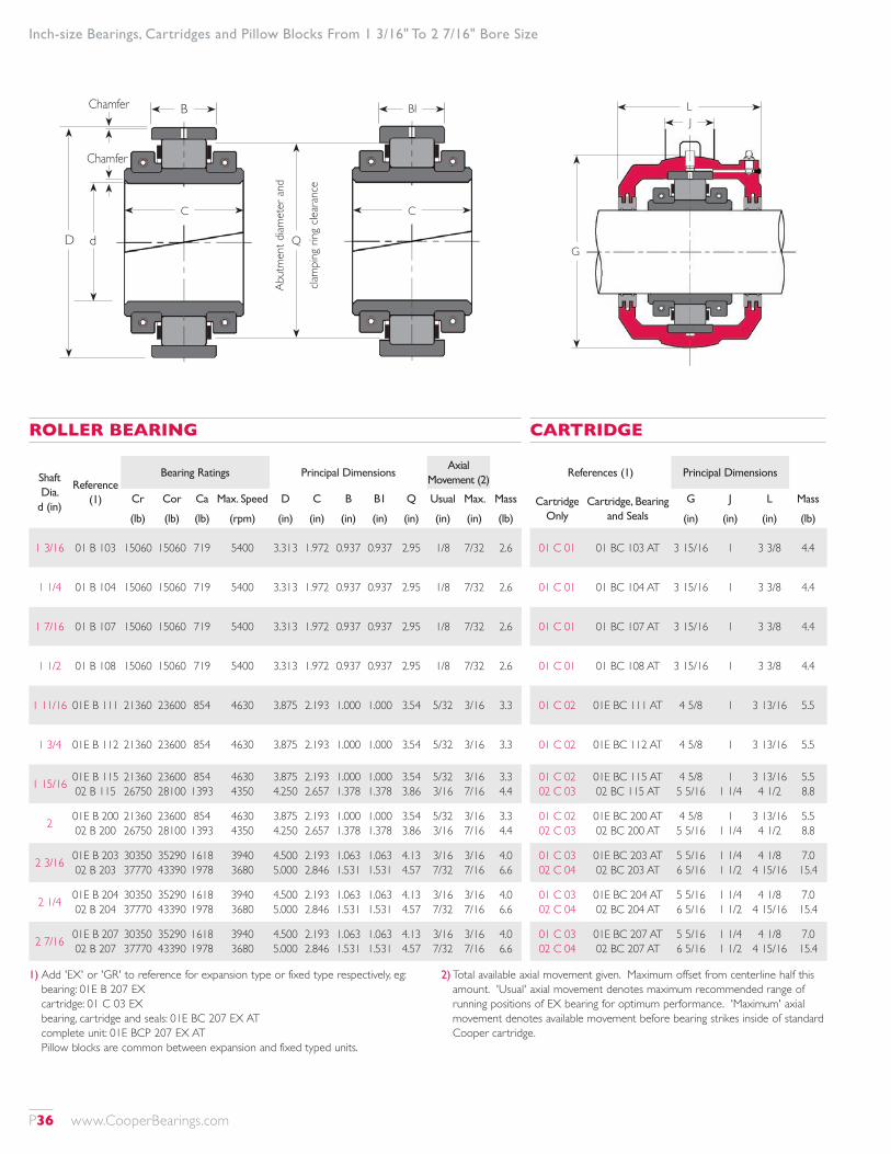
Inch-size Bearings, Cartridges and Pillow Blocks From 1 3/16" To 2 7/16" Bore Size
Shaft Dia.
d (in)
Reference (1)
Bearing Ratings Principal DimensionsAxial
Movement (2)
Cr Cor Ca Max. Speed D C B B1 Q Usual Max. Mass
(lb) (lb) (lb) (rpm) (in) (in) (in) (in) (in) (in) (in) (lb)
1 3/16 01 B 103 15060 15060 719 5400 3.313 1.972 0.937 0.937 2.95 1/8 7/32 2.6
1 1/4 01 B 104 15060 15060 719 5400 3.313 1.972 0.937 0.937 2.95 1/8 7/32 2.6
1 7/16 01 B 107 15060 15060 719 5400 3.313 1.972 0.937 0.937 2.95 1/8 7/32 2.6
1 1/2 01 B 108 15060 15060 719 5400 3.313 1.972 0.937 0.937 2.95 1/8 7/32 2.6
1 11/16 01E B 111 21360 23600 854 4630 3.875 2.193 1.000 1.000 3.54 5/32 3/16 3.3
1 3/4 01E B 112 21360 23600 854 4630 3.875 2.193 1.000 1.000 3.54 5/32 3/16 3.3
1 15/16 01E B 115 02 B 115
21360 26750
23600 28100
854 1393
4630 4350
3.875 4.250
2.193 2.657
1.000 1.378
1.000 1.378
3.54 3.86
5/32 3/16
3/16 7/16
3.3 4.4
2 01E B 200 02 B 200
21360 26750
23600 28100
854 1393
4630 4350
3.875 4.250
2.193 2.657
1.000 1.378
1.000 1.378
3.54 3.86
5/32 3/16
3/16 7/16
3.3 4.4
2 3/16 01E B 203 02 B 203
30350 37770
35290 43390
1618 1978
3940 3680
4.500 5.000
2.193 2.846
1.063 1.531
1.063 1.531
4.13 4.57
3/16 7/32
3/16 7/16
4.0 6.6
2 1/4 01E B 204 02 B 204
30350 37770
35290 43390
1618 1978
3940 3680
4.500 5.000
2.193 2.846
1.063 1.531
1.063 1.531
4.13 4.57
3/16 7/32
3/16 7/16
4.0 6.6
2 7/16 01E B 207 02 B 207
30350 37770
35290 43390
1618 1978
3940 3680
4.500 5.000
2.193 2.846
1.063 1.531
1.063 1.531
4.13 4.57
3/16 7/32
3/16 7/16
4.0 6.6
ROLLER BEARING
References (1) Principal Dimensions
Cartridge Only
Cartridge, Bearing and Seals
G J L Mass
(in) (in) (in) (lb)
01 C 01 01 BC 103 AT 3 15/16 1 3 3/8 4.4
01 C 01 01 BC 104 AT 3 15/16 1 3 3/8 4.4
01 C 01 01 BC 107 AT 3 15/16 1 3 3/8 4.4
01 C 01 01 BC 108 AT 3 15/16 1 3 3/8 4.4
01 C 02 01E BC 111 AT 4 5/8 1 3 13/16 5.5
01 C 02 01E BC 112 AT 4 5/8 1 3 13/16 5.5
01 C 02 02 C 03
01E BC 115 AT 02 BC 115 AT
4 5/8 5 5/16
1 1 1/4
3 13/16 4 1/2
5.5 8.8
01 C 02 02 C 03
01E BC 200 AT 02 BC 200 AT
4 5/8 5 5/16
1 1 1/4
3 13/16 4 1/2
5.5 8.8
01 C 03 02 C 04
01E BC 203 AT 02 BC 203 AT
5 5/16 6 5/16
1 1/4 1 1/2
4 1/8 4 15/16
7.0 15.4
01 C 03 02 C 04
01E BC 204 AT 02 BC 204 AT
5 5/16 6 5/16
1 1/4 1 1/2
4 1/8 4 15/16
7.0 15.4
01 C 03 02 C 04
01E BC 207 AT 02 BC 207 AT
5 5/16 6 5/16
1 1/4 1 1/2
4 1/8 4 15/16
7.0 15.4
CARTRIDGE
1) Add 'EX' or 'GR' to reference for expansion type or fixed type respectively, eg: bearing: 01E B 207 EX cartridge: 01 C 03 EX bearing, cartridge and seals: 01E BC 207 EX AT complete unit: 01E BCP 207 EX AT Pillow blocks are common between expansion and fixed typed units.
2) Total available axial movement given. Maximum offset from centerline half this amount. 'Usual' axial movement denotes maximum recommended range of running positions of EX bearing for optimum performance. 'Maximum' axial movement denotes available movement before bearing strikes inside of standard Cooper cartridge.
G
LJ
B
D d
Chamfer
Chamfer
BI
C
Q
Abut
men
t diam
eter
and
clam
ping
ring
clea
ranc
e
C
P36 www.CooperBearings.com
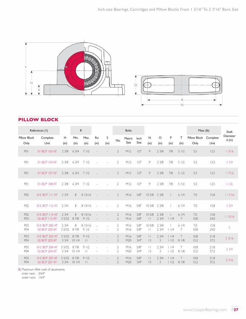
Inch-size Bearings, Cartridges and Pillow Blocks From 1 3/16" To 2 7/16" Bore Size
References (1) R Bolts Mass (lb) Shaft Diameter
d (in)Pillow Block Complete H Min. Max. Ro S
No.Metric Size
Inch Size
N O P T Pillow Block Complete
Only Unit (in) (in) (in) (in) (in) (in) (in) (in) (in) Only Unit
P01 01 BCP 103 AT 2 3/8 6 3/4 7 1/2 - - 2 M12 1/2" 9 2 3/8 7/8 5 1/2 5.5 12.5 1 3/16
P01 01 BCP 104 AT 2 3/8 6 3/4 7 1/2 - - 2 M12 1/2" 9 2 3/8 7/8 5 1/2 5.5 12.5 1 1/4
P01 01 BCP 107 AT 2 3/8 6 3/4 7 1/2 - - 2 M12 1/2" 9 2 3/8 7/8 5 1/2 5.5 12.5 1 7/16
P01 01 BCP 108 AT 2 3/8 6 3/4 7 1/2 - - 2 M12 1/2" 9 2 3/8 7/8 5 1/2 5.5 12.5 1 1/2
P02 01E BCP 111 AT 2 3/4 8 8 15/16 - - 2 M16 5/8" 10 5/8 2 3/8 1 6 1/4 7.0 15.8 1 11/16
P02 01E BCP 112 AT 2 /34 8 8 15/16 - - 2 M16 5/8" 10 5/8 2 3/8 1 6 1/4 7.0 15.8 1 3/4
P02 P03
01E BCP 115 AT 02 BCP 115 AT
2 3/4 3 5/32
8 8 7/8
8 15/16 9 1/2
- -
- -
2 2
M16 M16
5/8" 5/8"
10 5/8 11
2 3/8 2 3/4
1 1 1/4
6 1/4 7
7.0 10.8
15.8 24.0 1 15/16
P03 P04
01E BCP 200 AT 02 BCP 200 AT
2 3/4 3 5/32
8 8 7/8
8 15/16 9 1/2
- -
- -
2 2
M16 M16
5/8" 5/8"
10 5/8 11
2 3/8 2 3/4
1 1 1/4
6 1/4 7
7.0 10.8
15.8 24.0 2
P03 P04
01E BCP 203 AT 02 BCP 203 AT
3 5/32 3 3/4
8 7/8 10 1/4
9 1/2 11
- -
- -
2 2
M16 M20
5/8" 3/4"
11 13
2 3/4 3
1 1/4 1 1/2
7 8 1/8
10.8 15.2
21.8 37.2 2 3/16
P03 P04
01E BCP 204 AT 02 BCP 204 AT
3 5/32 3 3/4
8 7/8 10 1/4
9 1/2 11
- -
- -
2 2
M16 M20
5/8" 3/4"
11 13
2 3/4 3
1 1/4 1 1/2
7 8 1/8
10.8 15.2
21.8 37.2 2 1/4
P03 P04
01E BCP 207 AT 02 BCP 207 AT
3 5/32 3 3/4
8 7/8 10 1/4
9 1/2 11
- -
- -
2 2
M16 M20
5/8" 3/4"
11 13
2 3/4 3
1 1/4 1 1/2
7 8 1/8
10.8 15.2
21.8 37.2 2 716
PILLOW BLOCK
3) Maximum fillet radii of abutments: inner race: 3/64" outer race: 1/64"
T
H
P
RN
O
www.CooperBearings.com P37

Inch-size Bearings, Cartridges and Pillow Blocks From 2 1/2" To 3 1/4" Bore Size
1) Add 'EX' or 'GR' to reference for expansion type or fixed type respectively, eg: bearing: 01E B 215 EX cartridge: 01 C 04 EX bearing, cartridge and seals: 01E BC 215 EX AT complete unit: 01E BCP 215 EX AT Pillow blocks are common between expansion and fixed typed units.
2) Total available axial movement given. Maximum offset from centerline half this amount. 'Usual' axial movement denotes maximum recommended range of running positions of EX bearing for optimum performance. 'Maximum' axial movement denotes available movement before bearing strikes inside of standard Cooper cartridge.
Shaft Dia.
d (in)
Reference (1)
Bearing Ratings Principal DimensionsAxial
Movement (2)
Cr Cor Ca Max. Speed D C B B1 Q Usual Max. Mass
(lb) (lb) (lb) (rpm) (in) (in) (in) (in) (in) (in) (in) (lb)
2 1/2 01E B 208 02 B 208
30350 37770
35290 43390
1618 1978
3940 3680
4.500 5.000
2.193 2.846
1.063 1.531
1.063 1.531
4.13 4.57
3/16 7/32
3/16 7/16
4.0 6.6
2 11/16 01E B 211 02 B 211
37320 51480
44290 60250
2427 2382
3310 3080
5.250 5.875
2.409 3.252
1.252 1.815
1.252 1.815
4.88 5.43
3/16 1/4
1/4 17/32
5.5 11.0
2 3/4 01E B 212 02 B 212
37320 51480
44290 60250
2427 2382
3310 3080
5.250 5.875
2.409 3.252
1.252 1.815
1.252 1.815
4.88 5.43
3/16 1/4
1/4 17/32
5.5 11.0
2 15/16100 B 215 01E B 215 02 B 215
20460 37320 51480
28770 44290 60250
1573 2427 2382
4215 3310 3080
4.500 5.250 5.875
1.890 2.409 3.252
1.063 1.252 1.815
1.063 1.252 1.815
4.02 4.88 5.43
1/8 3/16 1/4
1/4 1/4
17/32
2.6 5.5 11.0
3100 B 300 01E B 300 02 B 300
20460 37320 51480
28770 44290 60250
1573 2427 2382
4215 3310 3080
4.500 5.250 5.875
1.890 2.409 3.252
1.063 1.252 1.815
1.063 1.252 1.815
4.02 4.88 5.43
1/8 3/16 1/4
1/4 1/4
17/32
2.6 5.5 11.0
3 3/16 01E B 303 02 B 303
52600 62940
67220 77550
3057 4001
2790 2520
6.000 6.688
2.783 3.531
1.531 1.906
1.531 1.906
5.59 6.14
1/4 9/32
3/8 9/16
8.8 15.4
3 1/4 01E B 304 02 B 304
52600 62940
67220 77550
3057 4001
2790 2520
6.000 6.688
2.783 3.531
1.531 1.906
1.531 1.906
5.59 6.14
1/4 9/32
3/8 9/16
8.8 15.4
ROLLER BEARING
References (1) Principal Dimensions
Cartridge Only
Cartridge, Bearing and Seals
G J L Mass
(in) (in) (in) (lb)
01 C 03 02 C 04
01E BC 208 AT 02 BC 208 AT
5 5/16 6 3/16
1 1/4 1 1/2
4 1/8 4 15/16
7.0 15.4
01 C 04 02 C 05
01E BC 211 AT 02 BC 211 AT
6 3/16 7
1 1/2 2
4 1/2 5 1/2
12.1 19.8
01 C 04 02 C 05
01E BC 212 AT 02 BC 212 AT
6 3/16 7
1 1/2 2
4 1/2 5 1/2
12.1 19.8
100 C 03 01 C 04 02 C 05
100 BC 215 AT 01E BC 215 AT 02 BC 215 AT
5 5/16 6 3/16
7
1 1/4 1 1/2
2
4 1/8 4 1/2 5 1/2
7.9 12.1 19.8
100 C 03 01 C 04 02 C 05
100 BC 300 AT 01E BC 300 AT 02 BC 300 AT
5 5/16 6 3/16
7
1 1/4 1 1/2
2
4 1/8 4 1/2 5 1/2
7.9 12.1 19.8
01 C 05 02 C 06
01E BC 303 AT 02 BC 303 AT
7 8
2 2
5 3/8 6 1/16
15.4 22
01 C 05 02 C 06
01E BC 304 AT 02 BC 304 AT
7 8
2 2
5 3/8 6 1/16
15.4 22
CARTRIDGE
G
LJ
B
D d
Chamfer
Chamfer
BI
C
Q
Abut
men
t diam
eter
and
clam
ping
ring
clea
ranc
e
C
P38 www.CooperBearings.com
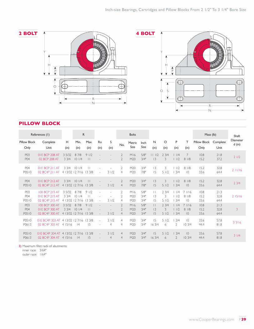
T
H
P
RN
O S
T
H
P
RN
O
Inch-size Bearings, Cartridges and Pillow Blocks From 2 1/2" To 3 1/4" Bore Size
3) Maximum fillet radii of abutments: inner race: 3/64" outer race: 1/64"
2 BOLT 4 BOLT
PILLOW BLOCK
References (1) R Bolts Mass (lb) Shaft Diameter
d (in)Pillow Block Complete H Min. Max. Ro S
No.Metric Size
Inch Size
N O P T Pillow Block Complete
Only Unit (in) (in) (in) (in) (in) (in) (in) (in) (in) Only Unit
P03 P04
01E BCP 208 AT 02 BCP 208 AT
3 5/32 3 3/4
8 7/8 10 1/4
9 1/2 11
- -
- -
2 2
M16 M20
5/8" 3/4"
11 1/2 13
2 3/4 3
1 1/4 1 1/2
7 8 1/8
10.8 15.2
21.8 37.2 2 1/2
P04 P0510
01E BCP 211 AT 02 BC4P 211 AT
3 3/4 4 13/32
10 1/4 12 7/16
11 13 3/8
- -
- 3 1/2
2 4
M20 M20
3/4" 7/8"
13 15
3 5 1/2
1 1/2 1 3/4
8 1/8 10
15.2 33.6
32.8 64.4 2 11/16
P04 P0510
01E BCP 212 AT 02 BC4P 212 AT
3 3/4 4 13/32
10 1/4 12 7/16
11 13 3/8
- -
- 3 1/2
2 4
M20 M20
3/4" 7/8"
13 15
3 5 1/2
1 1/2 1 3/4
8 1/8 10
15.2 33.6
32.8 64.4 2 3/4
P03 P04
P0510
100 BCP 215 AT 01E BCP 215 AT 02 BC4P 215 AT
3 5/32 3 3/4
4 13/32
8 7/8 10 1/4 12 7/16
9 1/2 11
13 3/8
- - -
- -
3 1/2
2 2 4
M16 M20 M20
5/8" 3/4" 3/4"
11 13 15
2 3/4 3
5 1/2
1 1/4 1 1/2 1 3/4
7 1/16 8 1/8 10
10.8 15.2 33.6
21.3 32.8 64.4
2 15/16
P03 P04
P0510
100 BCP 300 AT 01E BCP 300 AT 02 BC4P 300 AT
3 5/32 3 3/4
4 13/32
8 7/8 10 1/4 12 7/16
9 1/2 11
13 3/8
- - -
- -
3 1/2
2 2 4
M16 M20 M20
5/8" 3/4" 3/4"
11 13 15
2 3/4 3
5 1/2
1 1/4 1 1/2 1 3/4
7 1/16 8 1/8 10
10.8 15.2 33.6
21.3 32.8 64.4
3
P0510 P0613
01E BC4P 303 AT 02 BC4P 303 AT
4 13/32 4 15/16
12 7/16 14
13 3/8 15
- -
3 1/2 4
4 4
M20 M20
3/4" 3/4"
15 16 3/4
5 1/2 6
1 3/4 2
10 10 3/4
33.6 44.4
57.8 81.8 3 3/16
P0510 P0613
01E BC4P 304 AT 02 BC4P 304 AT
4 13/32 4 15/16
12 7/16 14
13 3/8 15
- -
3 1/2 4
4 4
M20 M20
3/4" 3/4"
15 16 3/4
5 1/2 6
1 3/4 2
10 10 3/4
33.6 44.4
57.8 81.8 3 1/4
www.CooperBearings.com P39
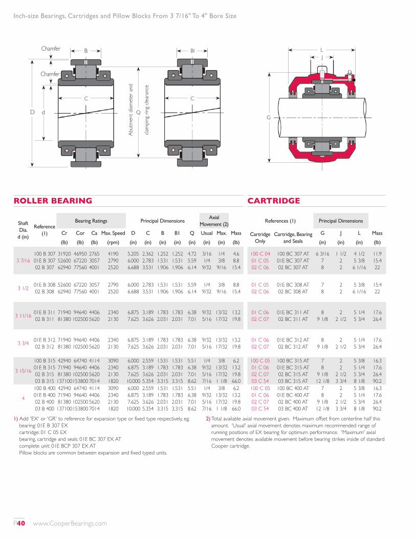
Inch-size Bearings, Cartridges and Pillow Blocks From 3 7/16" To 4" Bore Size
1) Add 'EX' or 'GR' to reference for expansion type or fixed type respectively, eg: bearing: 01E B 307 EX cartridge: 01 C 05 EX bearing, cartridge and seals: 01E BC 307 EX AT complete unit: 01E BCP 307 EX AT Pillow blocks are common between expansion and fixed typed units.
2) Total available axial movement given. Maximum offset from centerline half this amount. 'Usual' axial movement denotes maximum recommended range of running positions of EX bearing for optimum performance. 'Maximum' axial movement denotes available movement before bearing strikes inside of standard Cooper cartridge.
Shaft Dia.
d (in)
Reference (1)
Bearing Ratings Principal DimensionsAxial
Movement (2)
Cr Cor Ca Max. Speed D C B B1 Q Usual Max. Mass
(lb) (lb) (lb) (rpm) (in) (in) (in) (in) (in) (in) (in) (lb)
3 7/16100 B 307 01E B 307 02 B 307
31920 52600 62940
46950 67220 77560
2765 3057 4001
4190 2790 2520
5.205 6.000 6.688
2.362 2.783 3.531
1.252 1.531 1.906
1.252 1.531 1.906
4.72 5.59 6.14
3/16 1/4 9/32
1/4 3/8 9/16
4.6 8.8 15.4
3 1/2 01E B 308 02 B 308
52600 62940
67220 77560
3057 4001
2790 2520
6.000 6.688
2.783 3.531
1.531 1.906
1.531 1.906
5.59 6.14
1/4 9/32
3/8 9/16
8.8 15.4
3 11/16 01E B 311 02 B 311
71940 81380
94640 102500
4406 5620
2340 2130
6.875 7.625
3.189 3.626
1.783 2.031
1.783 2.031
6.38 7.01
9/32 5/16
13/32 17/32
13.2 19.8
3 3/4 01E B 312 02 B 312
71940 81380
94640 102500
4406 5620
2340 2130
6.875 7.625
3.189 3.626
1.783 2.031
1.783 2.031
6.38 7.01
9/32 5/16
13/32 17/32
13.2 19.8
3 15/16
100 B 315 01E B 315 02 B 315 03 B 315
42940 71940 81380 137100
64740 94640 102500 153800
4114 4406 5620 7014
3090 2340 2130 1820
6.000 6.875 7.625 10.000
2.559 3.189 3.626 5.354
1.531 1.783 2.031 3.315
1.531 1.783 2.031 3.315
5.51 6.38 7.01 8.62
1/4 9/32 5/16 7/16
3/8 13/32 17/32 1 1/8
6.2 13.2 19.8 66.0
4
100 B 400 01E B 400 02 B 400 03 B 400
42940 71940 81380 137100
64740 94640 102500 153800
4114 4406 5620 7014
3090 2340 2130 1820
6.000 6.875 7.625 10.000
2.559 3.189 3.626 5.354
1.531 1.783 2.031 3.315
1.531 1.783 2.031 3.315
5.51 6.38 7.01 8.62
1/4 9/32 5/16 7/16
3/8 13/32 17/32 1 1/8
6.2 13.2 19.8 66.0
ROLLER BEARING
References (1) Principal Dimensions
Cartridge Only
Cartridge, Bearing and Seals
G J L Mass
(in) (in) (in) (lb)
100 C 04 01 C 05 02 C 06
100 BC 307 AT 01E BC 307 AT 02 BC 307 AT
6 3/16 7 8
1 1/2 2 2
4 1/2 5 3/8 6 1/16
11.9 15.4 22
01 C 05 02 C 06
01E BC 308 AT 02 BC 308 AT
7 8
2 2
5 3/8 6 1/16
15.4 22
01 C 06 02 C 07
01E BC 311 AT 02 BC 311 AT
8 9 1/8
2 2 1/2
5 1/4 5 3/4
17.6 26.4
01 C 06 02 C 07
01E BC 312 AT 02 BC 312 AT
8 9 1/8
2 2 1/2
5 1/4 5 3/4
17.6 26.4
100 C 05 01 C 06 02 C 07 03 C 54
100 BC 315 AT 01E BC 315 AT 02 BC 315 AT 03 BC 315 AT
7 8
9 1/8 12 1/8
2 2
2 1/2 3 3/4
5 3/8 5 1/4 5 3/4 8 1/8
16.3 17.6 26.4 90.2
100 C 05 01 C 06 02 C 07 03 C 54
100 BC 400 AT 01E BC 400 AT 02 BC 400 AT 03 BC 400 AT
7 8
9 1/8 12 1/8
2 2
2 1/2 3 3/4
5 3/8 5 1/4 5 3/4 8 1/8
16.3 17.6 26.4 90.2
CARTRIDGE
G
LJ
B
D d
Chamfer
Chamfer
BI
C
Q
Abut
men
t diam
eter
and
clam
ping
ring
clea
ranc
e
C
P40 www.CooperBearings.com
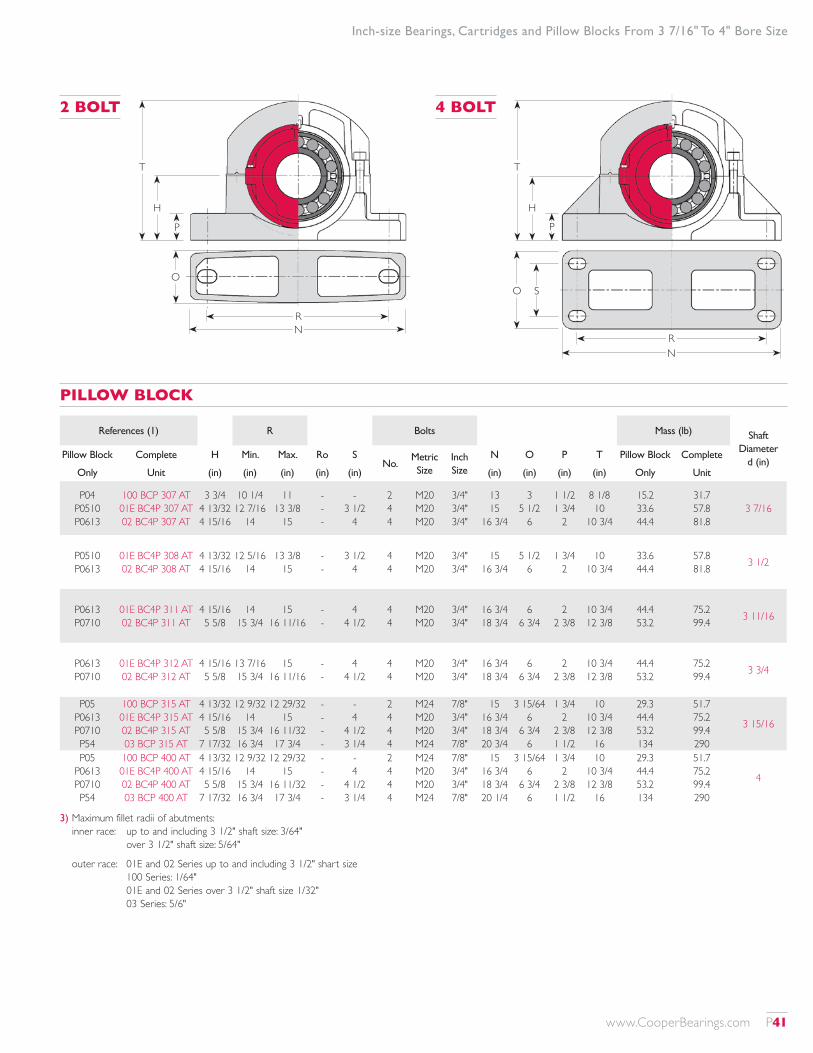
T
H
P
RN
O S
T
H
P
RN
O
Inch-size Bearings, Cartridges and Pillow Blocks From 3 7/16" To 4" Bore Size
3) Maximum fillet radii of abutments: inner race: up to and including 3 1/2" shaft size: 3/64"
over 3 1/2" shaft size: 5/64"
outer race: 01E and 02 Series up to and including 3 1/2" shart size 100 Series: 1/64" 01E and 02 Series over 3 1/2" shaft size 1/32" 03 Series: 5/6"
2 BOLT 4 BOLT
PILLOW BLOCK
References (1) R Bolts Mass (lb) Shaft Diameter
d (in)Pillow Block Complete H Min. Max. Ro S
No.Metric Size
Inch Size
N O P T Pillow Block Complete
Only Unit (in) (in) (in) (in) (in) (in) (in) (in) (in) Only Unit
P04 P0510 P0613
100 BCP 307 AT 01E BC4P 307 AT 02 BC4P 307 AT
3 3/4 4 13/32 4 15/16
10 1/4 12 7/16
14
11 13 3/8
15
- - -
- 3 1/2
4
2 4 4
M20 M20 M20
3/4" 3/4" 3/4"
13 15
16 3/4
3 5 1/2
6
1 1/2 1 3/4
2
8 1/8 10
10 3/4
15.2 33.6 44.4
31.7 57.8 81.8
3 7/16
P0510 P0613
01E BC4P 308 AT 02 BC4P 308 AT
4 13/32 4 15/16
12 5/16 14
13 3/8 15
- -
3 1/2 4
4 4
M20 M20
3/4" 3/4"
15 16 3/4
5 1/2 6
1 3/4 2
10 10 3/4
33.6 44.4
57.8 81.8 3 1/2
P0613 P0710
01E BC4P 311 AT 02 BC4P 311 AT
4 15/16 5 5/8
14 15 3/4
15 16 11/16
- -
4 4 1/2
4 4
M20 M20
3/4" 3/4"
16 3/4 18 3/4
6 6 3/4
2 2 3/8
10 3/4 12 3/8
44.4 53.2
75.2 99.4 3 11/16
P0613 P0710
01E BC4P 312 AT 02 BC4P 312 AT
4 15/16 5 5/8
13 7/16 15 3/4
15 16 11/16
- -
4 4 1/2
4 4
M20 M20
3/4" 3/4"
16 3/4 18 3/4
6 6 3/4
2 2 3/8
10 3/4 12 3/8
44.4 53.2
75.2 99.4 3 3/4
P05 P0613 P0710 P54
100 BCP 315 AT 01E BC4P 315 AT 02 BC4P 315 AT 03 BCP 315 AT
4 13/32 4 15/16 5 5/8
7 17/32
12 9/32 14
15 3/4 16 3/4
12 29/32 15
16 11/32 17 3/4
- - - -
- 4
4 1/2 3 1/4
2 4 4 4
M24 M20 M20 M24
7/8" 3/4" 3/4" 7/8"
15 16 3/4 18 3/4 20 3/4
3 15/64 6
6 3/4 6
1 3/4 2
2 3/8 1 1/2
10 10 3/4 12 3/8
16
29.3 44.4 53.2 134
51.7 75.2 99.4 290
3 15/16
P05 P0613 P0710 P54
100 BCP 400 AT 01E BC4P 400 AT 02 BC4P 400 AT 03 BCP 400 AT
4 13/32 4 15/16 5 5/8
7 17/32
12 9/32 14
15 3/4 16 3/4
12 29/32 15
16 11/32 17 3/4
- - - -
- 4
4 1/2 3 1/4
2 4 4 4
M24 M20 M20 M24
7/8" 3/4" 3/4" 7/8"
15 16 3/4 18 3/4 20 1/4
3 15/64 6
6 3/4 6
1 3/4 2
2 3/8 1 1/2
10 10 3/4 12 3/8
16
29.3 44.4 53.2 134
51.7 75.2 99.4 290
4
www.CooperBearings.com P41
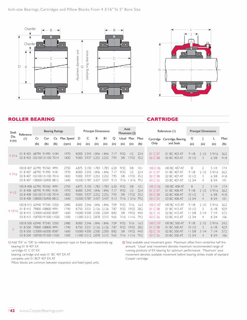
Inch-size Bearings, Cartridges and Pillow Blocks From 4 3/16" To 5" Bore Size
1) Add 'EX' or 'GR' to reference for expansion type or fixed type respectively, eg: bearing: 01 B 407 EX cartridge: 01 C 07 EX bearing, cartridge and seals: 01 BC 407 EX AT complete unit: 01 BCP 407 EX AT Pillow blocks are common between expansion and fixed typed units.
2) Total available axial movement given. Maximum offset from centerline half this amount. 'Usual' axial movement denotes maximum recommended range of running positions of EX bearing for optimum performance. 'Maximum' axial movement denotes available movement before bearing strikes inside of standard Cooper cartridge.
Shaft Dia.
d (in)
Reference (1)
Bearing Ratings Principal DimensionsAxial
Movement (2)
Cr Cor Ca Max. Speed D C B B1 Q Usual Max. Mass
(lb) (lb) (lb) (rpm) (in) (in) (in) (in) (in) (in) (in) (lb)
4 3/16 01 B 403 02 B 403
68790 102100
91490 131100
4184 7014
1970 1820
8.000 9.000
3.343 3.937
1.846 2.252
1.846 2.252
7.17 7.95
9/32 3/8
1/2 17/32
22.4 35.2
4 7/16
100 B 407 01 B 407 02 B 407 03 B 407
62790 68790 102100 138000
95760 91490 131100 156900
4991 4181 7014 8812
2750 1970 1820 1640
6.875 8.000 9.000 10.500
3.150 3.343 3.937 5.787
1.783 1.846 2.252 3.437
1.783 1.846 2.252 3.437
6.30 7.17 7.95 9.13
9/32 9/32 3/8 7/16
3/8 1/2
17/32 1 3/16
10.1 22.4 35.2 79.2
4 1/2
100 B 408 01 B 408 02 B 408 03 B 408
62790 68790 102100 138000
95760 91490 131100 156900
4991 4181 7014 8812
2750 1970 1820 1640
6.875 8.000 9.000 10.500
3.150 3.343 3.937 5.787
1.783 1.846 2.252 3.437
1.783 1.846 2.252 3.437
6.30 7.17 7.95 9.13
9/32 9/32 3/8 7/16
3/8 1/2
17/32 1 3/16
10.1 22.4 35.2 79.2
4 15/16
100 B 415 01 B 415 02 B 415 03 B 415
62940 79800 123000 158700
97340 108800 160300 191500
5350 4991 8587 11020
2480 1740 1600 1500
8.000 8.750 10.000 11.000
3.346 3.531 4.500 5.512
1.846 2.126 2.500 2.878
1.846 2.126 2.500 3.315
7.09 7.87 8.82 9.65
9/32 9/32 3/8 7/16
7/16 19/32 19/32 11/16
16.3 28.2 44.0 79.2
5
100 B 500 01 B 500 02 B 500 03 B 500
62940 79800 123000 158700
97340 108800 160300 191500
5350 4991 8587 11020
2480 1740 1600 1500
8.000 8.750 10.000 11.000
3.346 3.531 4.500 5.512
1.846 2.126 2.500 2.878
1.846 2.126 2.500 3.315
7.09 7.87 8.82 9.65
9/32 9/32 3/8 7/16
7/16 19/32 19/32 11/16
16.3 28.2 44.0 79.2
ROLLER BEARING
References (1) Principal Dimensions
Cartridge Only
Cartridge, Bearing and Seals
G J L Mass
(in) (in) (in) (lb)
01 C 07 02 C 08
01 BC 403 AT 02 BC 403 AT
9 1/8 10 1/2
2 1/2 3
5 9/16 6 3/8
26.2 41.8
100 C 06 01 C 07 02 C 08 03 C 55
100 BC 407 AT 01 BC 407 AT 02 BC 407 AT 03 BC 407 AT
8 9 1/8 10 1/2 12 3/4
2 2 1/2
3 4
5 1/4 5 9/16 6 3/8 8 3/4
17.4 26.2 41.8 101
100 C 06 01 C 07 02 C 08 03 C 55
100 BC 408 AT 01 BC 408 AT 02 BC 408 AT 03 BC 408 AT
8 9 1/8 10 1/2 12 3/4
2 2 1/2
3 4
5 1/4 5 9/16 6 3/8 8 3/4
17.4 26.2 41.8 101
100 C 07 01 C 08 02 C 10 03 C 56
100 BC 415 AT 01 BC 415 AT 02 BC 415 AT 03 BC 415 AT
9 1/8 10 1/2 11 5/8 12 3/4
2 1/2 3
3 1/4 4
5 9/16 6 1/8 7 1/4 8 3/4
26.2 42.9 57.2 106
100 C 07 01 C 08 02 C 10 03 C 56
100 BC 500 AT 01 BC 500 AT 02 BC 500 AT 03 BC 500 AT
9 1/8 10 1/2 11 5/8 12 3/4
2 1/2 3
3 1/4 4
5 9/16 6 1/8 7 1/4 8 3/4
24.2 42.9 57.2 106
CARTRIDGE
G
LJ
B
D d
Chamfer
Chamfer
BI
C
Q
Abut
men
t diam
eter
and
clam
ping
ring
clea
ranc
e
C
P42 www.CooperBearings.com
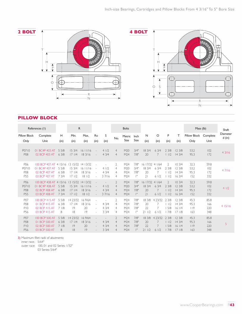
T
H
P
RN
O S
T
H
P
RN
O
Inch-size Bearings, Cartridges and Pillow Blocks From 4 3/16" To 5" Bore Size
3) Maximum fillet radii of abutments: inner race: 5/64" outer race: 100, 01 and 02 Series: 1/32" 03 Series: 5/64"
2 BOLT 4 BOLT
PILLOW BLOCK
References (1) R Bolts Mass (lb) Shaft Diameter
d (in)Pillow Block Complete H Min. Max. Ro S
No.Metric Size
Inch Size
N O P T Pillow Block Complete
Only Unit (in) (in) (in) (in) (in) (in) (in) (in) (in) Only Unit
P0710 P08
01 BC4P 403 AT 02 BCP 403 AT
5 5/8 6 3/8
15 3/4 17 1/4
16 11/16 18 3/16
- -
4 1/2 4 3/4
4 4
M20 M24
3/4" 7/8"
18 3/4 20
6 3/4 7
2 3/8 1 1/2
12 3/8 14 3/4
53.2 95.3
102 172 4 3/16
P06 P0710 P08 P55
100 BCP 407 AT 01 BC4P 407 AT 02 BCP 407 AT 03 BCP 407 AT
4 15/16 5 5/8 6 3/8 7 3/4
13 15/32 15 3/4 17 1/4 17 1/2
14 13/32 16 11/16 18 3/16 18 1/2
- - - -
- 4 1/2 4 3/4 3 7/16
2 4 4 4
M24 M20 M24 M24
7/8" 3/4" 7/8" 1"
16 17/32 18 3/4
20 21
4 1/64 6 3/4
7 6 1/2
2 2 3/8 1 1/2 1 1/2
10 3/4 12 3/8 14 3/4 16 3/4
32.3 53.2 95.3 152
59.8 102 172 332
4 7/16
P06 P0710 P08 P55
100 BCP 408 AT 01 BC4P 408 AT 02 BCP 408 AT 03 BCP 408 AT
4 15/16 5 5/8 6 3/8 7 3/4
13 15/32 15 3/4 17 1/4 17 1/2
14 13/32 16 11/16 18 3/16 18 1/2
- - - -
- 4 1/2 4 3/4 3 7/16
2 4 4 4
M24 M20 M24 M24
7/8" 3/4" 7/8" 1"
16 17/32 18 3/4
20 21
4 1/64 6 3/4
7 6 1/2
2 2 3/8 1 1/2 1 1/2
10 3/4 12 3/8 14 3/4 16 3/4
32.3 53.2 95.3 152
59.8 102 172 332
4 1/2
P07 P08 P10 P56
100 BCP 415 AT 01 BCP 415 AT 02 BCP 415 AT 03 BCP 415 AT
5 5/8 6 3/8 7 1/8
8
14 23/32 17 1/4
19 18
16 9/64 18 3/16
20 19
- - - -
- 4 3/4 4 3/4 3 3/4
2 4 4 4
M24 M24 M24 M24
7/8" 7/8" 7/8" 1"
18 3/8 20 22
21 1/2
4 23/32 7 7
6 1/2
2 3/8 1 1/2 1 5/8 1 7/8
12 3/8 14 3/4 16 1/4 17 1/8
45.3 95.3 119 163
85.8 166 220 348
4 15/16
P07 P08 P10 P56
100 BCP 500 AT 01 BCP 500 AT 02 BCP 500 AT 03 BCP 500 AT
5 5/8 6 3/8 7 1/8
8
14 23/32 17 1/4
19 18
16 9/64 18 3/16
20 19
- - - -
- 4 3/4 4 3/4 3 3/4
2 4 4 4
M24 M24 M24 M24
7/8" 7/8" 7/8" 1"
18 3/8 20 22
21 1/2
4 23/32 7 7
6 1/2
2 3/8 1 1/2 1 5/8 1 7/8
12 3/8 14 3/4 16 1/4 17 1/8
45.3 95.3 119 163
85.8 166 220 348
5
www.CooperBearings.com P43

1) Add 'EX' or 'GR' to reference for expansion type or fixed type respectively, eg: bearing: 01 B 507 EX cartridge: 01 C 09 EX bearing, cartridge and seals: 01 BC 507 EX AT complete unit: 01 BCP 507 EX AT Pillow blocks are common between expansion and fixed typed units.
2) Total available axial movement given. Maximum offset from centerline half this amount. 'Usual' axial movement denotes maximum recommended range of running positions of EX bearing for optimum performance. 'Maximum' axial movement denotes available movement before bearing strikes inside of standard Cooper cartridge.
Inch-size Bearings, Cartridges and Pillow Blocks From 5 3/16" To 6" Bore Size
Shaft Dia.
d (in)
Reference (1)
Bearing Ratings Principal DimensionsAxial
Movement (2)
Cr Cor Ca Max. Speed D C B B1 Q Usual Max. Mass
(lb) (lb) (lb) (rpm) (in) (in) (in) (in) (in) (in) (in) (lb)
5 3/16 01 B 503 02 B 503
88570 136700
121800 181600
5800 10210
1570 1450
9.500 10.750
3.874 4.626
2.189 2.626
2.189 2.626
8.50 9.45
5/16 3/8
5/8 19/32
33.0 52.8
5 7/16
100 B 507 01 B 507 02 B 507 03 B 507
74310 88570 136700 199200
116900 121800 181600 240300
6856 5800 10210 13220
2250 1570 1450 1340
8.750 9.500 10.750 12.000
3.543 3.874 4.626 5.787
2.126 2.189 2.626 3.126
2.126 2.189 2.626 3.563
7.68 8.50 9.45 10.63
9/32 5/16 3/8 1/2
1/2 5/8
19/32 11/16
20.5 33.0 52.8 96.8
5 1/2
100 B 508 01 B 508 02 B 508 03 B 508
74310 88570 136700 199200
116900 121800 181600 240300
6856 5800 10210 13220
2250 1570 1450 1340
8.750 9.500 10.750 12.000
3.543 3.874 4.626 5.787
2.126 2.189 2.626 3.126
2.126 2.189 2.626 3.563
7.68 8.50 9.45 10.63
9/32 5/16 3/8 1/2
1/2 5/8
19/32 11/16
20.5 33.0 52.8 96.8
5 15/16
100 B 515 01 B 515 02 B 515 03 B 515
89250 96210 162800 223500
136200 138500 225900 272700
7059 6609 11780 15600
2060 1450 1320 1220
9.500 10.000 11.500 13.000
3.543 3.874 4.874 6.299
2.189 2.189 2.689 3.189
2.189 2.189 2.689 3.815
8.46 9.06 10.16 11.50
5/16 5/16 3/8 1/2
5/8 5/8
19/32 5/8
22.9 36.5 63.8 125
6
100 B 600 01 B 600 02 B 600 03 B 600
89250 96210 162800 223500
136200 138500 225900 272700
7059 6609 11780 15600
2060 1450 1320 1220
9.500 10.000 11.500 13.000
3.543 3.874 4.874 6.299
2.189 2.189 2.689 3.189
2.189 2.189 2.689 3.815
8.46 9.06 10.16 11.50
5/16 5/16 3/8 1/2
5/8 5/8
19/32 3/8
22.9 36.5 63.8 125
ROLLER BEARING
References (1) Principal Dimensions
Cartridge Only
Cartridge, Bearing and Seals
G J L Mass
(in) (in) (in) (lb)
01 C 09 02 C 30
01 BC 503 AT 02 BC 503 AT
11 12 3/4
3 3 1/2
6 5/8 7 3/8
45.8 72.6
100 C 08 01 C 09 02 C 30 03 C 57
100 BC 507 AT 01 BC 507 AT 02 BC 507 AT 03 BC 507 AT
10 1/2 11
12 3/4 14
3 3
3 1/2 4 1/4
6 1/8 6 5/8 7 3/8 9 1/16
40.5 45.8 72.6 114
100 C 08 01 C 09 02 C 30 03 C 57
100 BC 508 AT 01 BC 508 AT 02 BC 508 AT 03 BC 508 AT
10 1/2 11
12 3/4 14
3 3
3 1/2 4 1/4
6 1/8 6 5/8 7 3/8 9 1/16
40.5 45.8 72.6 114
100 C 09 01 C 10 02 C 31 03 C 58
100 BC 515 AT 01 BC 515 AT 02 BC 515 AT 03 BC 515 AT
11 11 5/8 13 1/4 15 1/2
3 3 1/4 3 3/4 4 1/2
6 5/8 6 7/8 8 1/16
10
42.7 53.7 85.8 154
100 C 09 01 C 10 02 C 31 03 C 58
100 BC 600 AT 01 BC 600 AT 02 BC 600 AT 03 BC 600 AT
11 11 5/8 13 1/4 15 1/2
3 3 1/4 3 3/4 4 1/2
6 5/8 6 7/8 8 1/16
10
42.7 53.7 85.8 154
CARTRIDGE
G
LJ
B
D d
Chamfer
Chamfer
BI
C
Q
Abut
men
t diam
eter
and
clam
ping
ring
clea
ranc
e
C
P44 www.CooperBearings.com
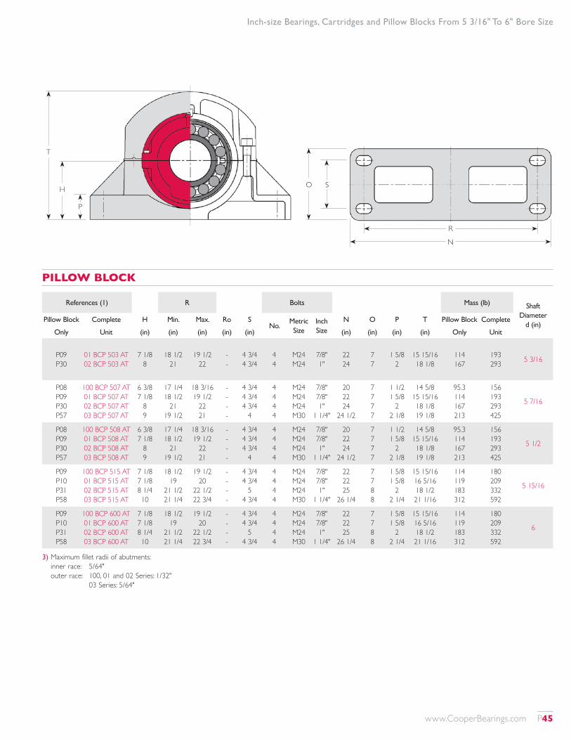
3) Maximum fillet radii of abutments: inner race: 5/64" outer race: 100, 01 and 02 Series: 1/32" 03 Series: 5/64"
Inch-size Bearings, Cartridges and Pillow Blocks From 5 3/16" To 6" Bore Size
T
H
P
R
N
O S
PILLOW BLOCK
References (1) R Bolts Mass (lb) Shaft Diameter
d (in)Pillow Block Complete H Min. Max. Ro S
No.Metric Size
Inch Size
N O P T Pillow Block Complete
Only Unit (in) (in) (in) (in) (in) (in) (in) (in) (in) Only Unit
P09 P30
01 BCP 503 AT 02 BCP 503 AT
7 1/8 8
18 1/2 21
19 1/2 22
- -
4 3/4 4 3/4
4 4
M24 M24
7/8" 1"
22 24
7 7
1 5/8 2
15 15/16 18 1/8
114 167
193 293 5 3/16
P08 P09 P30 P57
100 BCP 507 AT 01 BCP 507 AT 02 BCP 507 AT 03 BCP 507 AT
6 3/8 7 1/8
8 9
17 1/4 18 1/2
21 19 1/2
18 3/16 19 1/2
22 21
- - - -
4 3/4 4 3/4 4 3/4
4
4 4 4 4
M24 M24 M24 M30
7/8" 7/8" 1"
1 1/4"
20 22 24
24 1/2
7 7 7 7
1 1/2 1 5/8
2 2 1/8
14 5/8 15 15/16 18 1/8 19 1/8
95.3 114 167 213
156 193 293 425
5 7/16
P08 P09 P30 P57
100 BCP 508 AT 01 BCP 508 AT 02 BCP 508 AT 03 BCP 508 AT
6 3/8 7 1/8
8 9
17 1/4 18 1/2
21 19 1/2
18 3/16 19 1/2
22 21
- - - -
4 3/4 4 3/4 4 3/4
4
4 4 4 4
M24 M24 M24 M30
7/8" 7/8" 1"
1 1/4"
20 22 24
24 1/2
7 7 7 7
1 1/2 1 5/8
2 2 1/8
14 5/8 15 15/16 18 1/8 19 1/8
95.3 114 167 213
156 193 293 425
5 1/2
P09 P10 P31 P58
100 BCP 515 AT 01 BCP 515 AT 02 BCP 515 AT 03 BCP 515 AT
7 1/8 7 1/8 8 1/4 10
18 1/2 19
21 1/2 21 1/4
19 1/2 20
22 1/2 22 3/4
- - - -
4 3/4 4 3/4
5 4 3/4
4 4 4 4
M24 M24 M24 M30
7/8" 7/8" 1"
1 1/4"
22 22 25
26 1/4
7 7 8 8
1 5/8 1 5/8
2 2 1/4
15 15/16 16 5/16 18 1/2 21 1/16
114 119 183 312
180 209 332 592
5 15/16
P09 P10 P31 P58
100 BCP 600 AT 01 BCP 600 AT 02 BCP 600 AT 03 BCP 600 AT
7 1/8 7 1/8 8 1/4 10
18 1/2 19
21 1/2 21 1/4
19 1/2 20
22 1/2 22 3/4
- - - -
4 3/4 4 3/4
5 4 3/4
4 4 4 4
M24 M24 M24 M30
7/8" 7/8" 1"
1 1/4"
22 22 25
26 1/4
7 7 8 8
1 5/8 1 5/8
2 2 1/4
15 15/16 16 5/16 18 1/2 21 1/16
114 119 183 312
180 209 332 592
6
www.CooperBearings.com P45
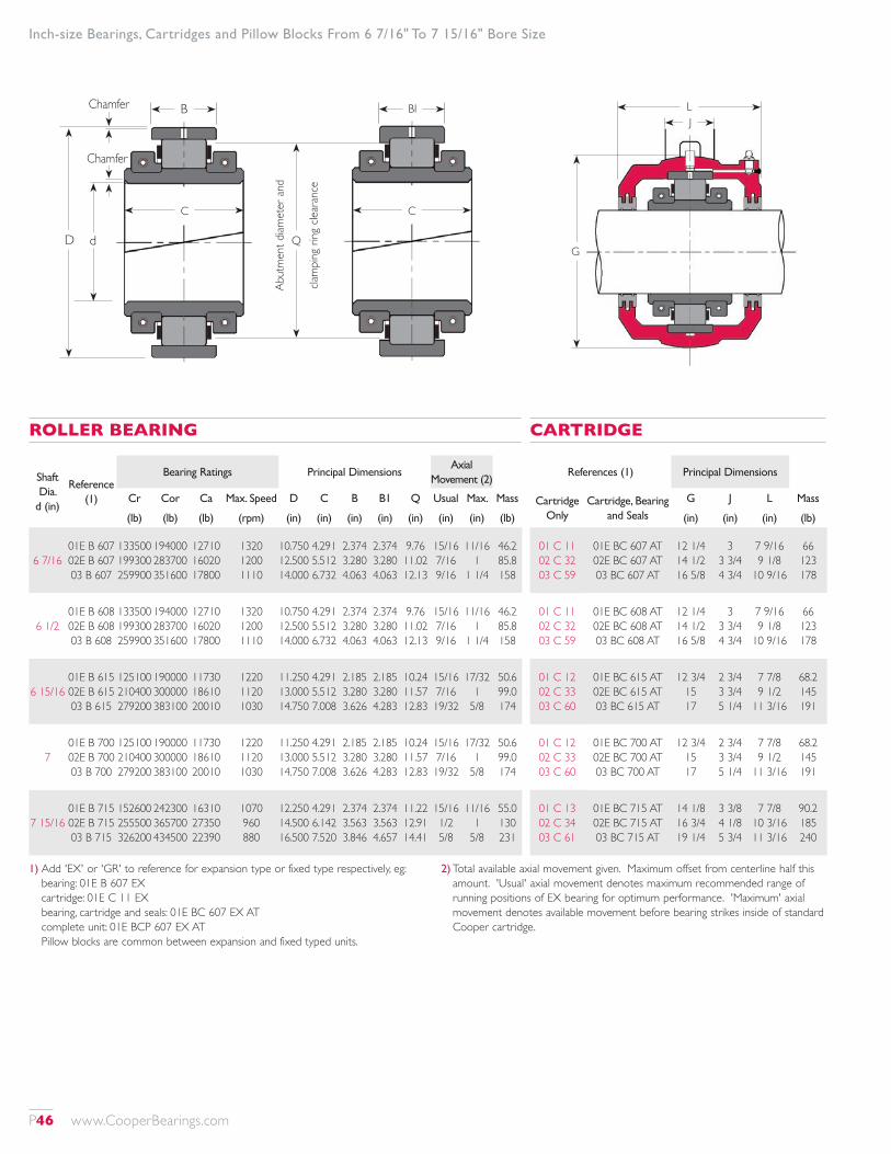
1) Add 'EX' or 'GR' to reference for expansion type or fixed type respectively, eg: bearing: 01E B 607 EX cartridge: 01E C 11 EX bearing, cartridge and seals: 01E BC 607 EX AT complete unit: 01E BCP 607 EX AT Pillow blocks are common between expansion and fixed typed units.
2) Total available axial movement given. Maximum offset from centerline half this amount. 'Usual' axial movement denotes maximum recommended range of running positions of EX bearing for optimum performance. 'Maximum' axial movement denotes available movement before bearing strikes inside of standard Cooper cartridge.
Inch-size Bearings, Cartridges and Pillow Blocks From 6 7/16" To 7 15/16" Bore Size
Shaft Dia.
d (in)
Reference (1)
Bearing Ratings Principal DimensionsAxial
Movement (2)
Cr Cor Ca Max. Speed D C B B1 Q Usual Max. Mass
(lb) (lb) (lb) (rpm) (in) (in) (in) (in) (in) (in) (in) (lb)
6 7/1601E B 607 02E B 607 03 B 607
133500 199300 259900
194000 283700 351600
12710 16020 17800
1320 1200 1110
10.750 12.500 14.000
4.291 5.512 6.732
2.374 3.280 4.063
2.374 3.280 4.063
9.76 11.02 12.13
15/16 7/16 9/16
11/16 1
1 1/4
46.2 85.8 158
6 1/201E B 608 02E B 608 03 B 608
133500 199300 259900
194000 283700 351600
12710 16020 17800
1320 1200 1110
10.750 12.500 14.000
4.291 5.512 6.732
2.374 3.280 4.063
2.374 3.280 4.063
9.76 11.02 12.13
15/16 7/16 9/16
11/16 1
1 1/4
46.2 85.8 158
6 15/1601E B 615 02E B 615 03 B 615
125100 210400 279200
190000 300000 383100
11730 18610 20010
1220 1120 1030
11.250 13.000 14.750
4.291 5.512 7.008
2.185 3.280 3.626
2.185 3.280 4.283
10.24 11.57 12.83
15/16 7/16 19/32
17/32 1
5/8
50.6 99.0 174
701E B 700 02E B 700 03 B 700
125100 210400 279200
190000 300000 383100
11730 18610 20010
1220 1120 1030
11.250 13.000 14.750
4.291 5.512 7.008
2.185 3.280 3.626
2.185 3.280 4.283
10.24 11.57 12.83
15/16 7/16 19/32
17/32 1
5/8
50.6 99.0 174
7 15/1601E B 715 02E B 715 03 B 715
152600 255500 326200
242300 365700 434500
16310 27350 22390
1070 960 880
12.250 14.500 16.500
4.291 6.142 7.520
2.374 3.563 3.846
2.374 3.563 4.657
11.22 12.91 14.41
15/16 1/2 5/8
11/16 1
5/8
55.0 130 231
ROLLER BEARING
References (1) Principal Dimensions
Cartridge Only
Cartridge, Bearing and Seals
G J L Mass
(in) (in) (in) (lb)
01 C 11 02 C 32 03 C 59
01E BC 607 AT 02E BC 607 AT 03 BC 607 AT
12 1/4 14 1/2 16 5/8
3 3 3/4 4 3/4
7 9/16 9 1/8
10 9/16
66 123 178
01 C 11 02 C 32 03 C 59
01E BC 608 AT 02E BC 608 AT 03 BC 608 AT
12 1/4 14 1/2 16 5/8
3 3 3/4 4 3/4
7 9/16 9 1/8
10 9/16
66 123 178
01 C 12 02 C 33 03 C 60
01E BC 615 AT 02E BC 615 AT 03 BC 615 AT
12 3/4 15 17
2 3/4 3 3/4 5 1/4
7 7/8 9 1/2
11 3/16
68.2 145 191
01 C 12 02 C 33 03 C 60
01E BC 700 AT 02E BC 700 AT 03 BC 700 AT
12 3/4 15 17
2 3/4 3 3/4 5 1/4
7 7/8 9 1/2
11 3/16
68.2 145 191
01 C 13 02 C 34 03 C 61
01E BC 715 AT 02E BC 715 AT 03 BC 715 AT
14 1/8 16 3/4 19 1/4
3 3/8 4 1/8 5 3/4
7 7/8 10 3/16 11 3/16
90.2 185 240
CARTRIDGE
G
LJ
B
D d
Chamfer
Chamfer
BI
C
Q
Abut
men
t diam
eter
and
clam
ping
ring
clea
ranc
e
C
P46 www.CooperBearings.com
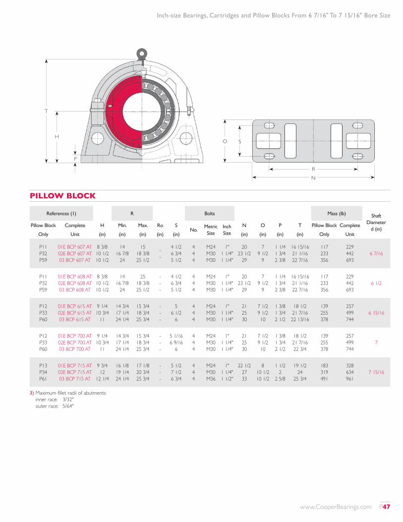
RN
O S
T
H
P
3) Maximum fillet radii of abutments: inner race: 3/32" outer race: 5/64"
Inch-size Bearings, Cartridges and Pillow Blocks From 6 7/16" To 7 15/16" Bore Size
PILLOW BLOCK
References (1) R Bolts Mass (lb) Shaft Diameter
d (in)Pillow Block Complete H Min. Max. Ro S
No.Metric Size
Inch Size
N O P T Pillow Block Complete
Only Unit (in) (in) (in) (in) (in) (in) (in) (in) (in) Only Unit
P11 P32 P59
01E BCP 607 AT 02E BCP 607 AT 03 BCP 607 AT
8 3/8 10 1/2 10 1/2
14 16 7/8
24
15 18 3/8 25 1/2
- -
4 1/2 6 3/4 5 1/2
4 4 4
M24 M30 M30
1" 1 1/4" 1 1/4"
20 23 1/2
29
7 9 1/2
9
1 1/4 1 3/4 2 3/8
16 15/16 21 1/16 22 7/16
117 233 356
229 442 693
6 7/16
P11 P32 P59
01E BCP 608 AT 02E BCP 608 AT 03 BCP 608 AT
8 3/8 10 1/2 10 1/2
14 16 7/8
24
25 18 3/8 25 1/2
- - -
4 1/2 6 3/4 5 1/2
4 4 4
M24 M30 M30
1" 1 1/4" 1 1/4"
20 23 1/2
29
7 9 1/2
9
1 1/4 1 3/4 2 3/8
16 15/16 21 1/16 22 7/16
117 233 356
229 442 693
6 1/2
P12 P33 P60
01E BCP 615 AT 02E BCP 615 AT 03 BCP 615 AT
9 1/4 10 3/4
11
14 3/4 17 1/4 24 1/4
15 3/4 18 3/4 25 3/4
- - -
5 6 1/2
6
4 4 4
M24 M30 M30
1" 1 1/4" 1 1/4"
21 25 30
7 1/2 9 1/2 10
1 3/8 1 3/4 2 1/2
18 1/2 21 7/16 22 13/16
139 255 378
257 499 744
6 15/16
P12 P33 P60
01E BCP 700 AT 02E BCP 700 AT 03 BCP 700 AT
9 1/4 10 3/4
11
14 3/4 17 1/4 24 1/4
15 3/4 18 3/4 25 3/4
- - -
5 1/16 6 9/16
6
4 4 4
M24 M30 M30
1" 1 1/4" 1 1/4"
21 25 30
7 1/2 9 1/2 10
1 3/8 1 3/4 2 1/2
18 1/2 21 7/16 22 3/4
139 255 378
257 499 744
7
P13 P34 P61
01E BCP 715 AT 02E BCP 715 AT 03 BCP 715 AT
9 3/4 12
12 1/4
16 1/8 19 1/4 24 1/4
17 1/8 20 3/4 25 3/4
- - -
5 1/2 7 1/2 6 3/4
4 4 4
M24 M30 M36
1" 1 1/4" 1 1/2"
22 1/2 27 33
8 10 1/2 10 1/2
1 1/2 2
2 5/8
19 1/2 24
25 3/4
183 319 491
328 634 961
7 15/16
www.CooperBearings.com P47

1) Add 'EX' or 'GR' to reference for expansion type or fixed type respectively, eg: bearing: 01E B 800 EX cartridge: 01 C 13 EX bearing, cartridge and seals: 01E BC 800 EX AT complete unit: 01E BCP 800 EX AT Pillow blocks are common between expansion and fixed typed units.
2) Total available axial movement given. Maximum offset from centerline half this amount. 'Usual' axial movement denotes maximum recommended range of running positions of EX bearing for optimum performance. 'Maximum' axial movement denotes available movement before bearing strikes inside of standard Cooper cartridge.
Inch-size Bearings, Cartridges and Pillow Blocks From 8" To 12" Bore Size
Shaft Dia.
d (in)
Reference (1)
Bearing Ratings Principal DimensionsAxial
Movement (2)
Cr Cor Ca Max. Speed D C B B1 Q Usual Max. Mass
(lb) (lb) (lb) (rpm) (in) (in) (in) (in) (in) (in) (in) (lb)
801E B 800 02E B 800 03 B 800
152600 255500 326200
242300 365700 434500
16310 27350 22390
1070 960 880
12.250 14.500 16.500
4.291 6.142 7.520
2.374 3.563 3.846
2.374 3.563 4.657
11.22 12.91 14.41
5/16 1/2 5/8
11/16 1
5/8
55.0 130 231
901E B 900 02E B 900 03 B 900
160600 277300 356500
267800 418800 486200
17950 31120 24590
930 850 760
13.500 15.500 18.500
4.528 6.417 8.346
2.500 3.563 4.315
2.500 3.563 5.189
12.40 13.94 16.14
5/16 1/2
11/16
3/4 1
11/16
70.4 150 319
1001E B 1000 02E B 1000 03 B 1000
180700 302600 399700
307400 446400 573500
21730 37650 29450
820 750 700
14.750 17.000 19.000
4.803 6.693 8.307
2.626 3.811 4.157
2.626 3.811 4.906
13.54 15.28 16.93
3/8 1/2
11/16
7/8 1 1/8 1 5/16
88.0 169 330
11
01E B 1100 02E B 1100 03X B 1100 03E B 1100
206100 347300 439700 473200
350700 547500 665400 726800
28500 42730 34390 34390
730 670 620 620
16.000 18.250 20.500 19.500
5.039 7.323 9.094 9.606
2.717 4.000 5.189 5.500
2.717 4.000 5.189 5.500
14.76 16.54 18.19 17.80
3/8 9/16 11/16 25/32
25/32 1 1/8 1 9/16 1 5/16
110 189 433 400
1201E B 1200 02E B 1200 03 B 1200
234000 373100 484700
423900 614900 744500
31150 48020 39120
650 610 560
17.250 19.500 22.000
5.630 7.598 9.606
2.937 4.063 5.500
2.937 4.063 5.500
15.91 17.64 19.53
3/8 9/16 3/4
1 1 3/16 1 11/16
132 271 524
ROLLER BEARING
References (1) Principal Dimensions
Cartridge Only
Cartridge, Bearing and Seals
G J L Mass
(in) (in) (in) (lb)
01 C 13 02 C 34 03 C 61
01E BC 800 AT 02E BC 800 AT 03 BC 800 AT
14 1/8 16 3/4 19 1/4
3 3/8 4 1/8 5 3/4
7 7/8 10 3/16 11 3/16
90.2 185 240
01 C 14 02 C 35 03 C 62
01E BC 900 AT 02E BC 900 AT 03 BC 900 AT
15 1/4 18
21 1/2
3 1/4 4 1/4 6 1/2
8 1/2 10 3/4 13 1/8
101 216 341
01 C 15 02 C 36 03 C 63
01E BC 1000 AT 02E BC 1000 AT 03 BC 1000 AT
16 1/2 19 1/2
22
3 1/2 4 5/8 6 1/2
8 3/4 11
13 1/8
128 231 354
01 C 16 02 C 37
03X C 64 03E C 83
01E BC 1100 AT 02E BC 1100 AT 03X BC 1100 AT 03E BC 1100 AT
17 7/8 20 3/4 23 1/2 22 1/2
3 3/4 5 1/8 6 1/2 6 1/2
9 1/8 11 13/16 13 7/8
14
154 288 440 449
01 C 17 02 C 38 03 C 65
01E BC 1200 AT 02E BC 1200 AT 03 BC 1200 AT
19 1/4 21 3/4 25 1/4
3 7/8 5
6 1/2
9 3/4 12
14 9/16
189 284 526
CARTRIDGE
G
LJ
B
D d
Chamfer
Chamfer
BI
C
Q
Abut
men
t diam
eter
and
clam
ping
ring
clea
ranc
e
C
P48 www.CooperBearings.com
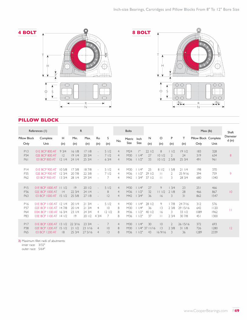
3) Maximum fillet radii of abutments: inner race: 3/32" outer race: 5/64"
Inch-size Bearings, Cartridges and Pillow Blocks From 8" To 12" Bore Size
RN
O S
T
H
P
T
H
P
R RoN
O S
Ro
4 BOLT 8 BOLT
PILLOW BLOCK
References (1) R Bolts Mass (lb) Shaft Diameter
d (in)Pillow Block Complete H Min. Max. Ro S
No.Metric Size
Inch Size
N O P T Pillow Block Complete
Only Unit (in) (in) (in) (in) (in) (in) (in) (in) (in) Only Unit
P13 P34 P61
01E BCP 800 AT 02E BCP 800 AT 03 BCP 800 AT
9 3/4 12
12 1/4
16 1/8 19 1/4 24 1/4
17 1/8 20 3/4 25 3/4
- - -
5 1/2 7 1/2 6 3/4
4 4 4
M24 M30 M36
1" 1 1/4" 1 1/2"
22 1/2 27 33
8 10 1/2 10 1/2
1 1/2 2
2 5/8
19 1/2 24
25 3/4
183 319 491
328 634 961
8
P14 P35 P62
01E BCP 900 AT 02E BCP 900 AT 03 BCP 900 AT
10 5/8 12 3/4 13 3/4
17 3/8 20 7/8 28 1/4
18 7/8 22 3/8 29 3/4
- - -
5 1/2 7 1/2
7
4 4 4
M30 M36 M42
1 1/4" 1 1/2" 1 3/4"
25 29 1/2 37 1/2
8 1/2 11 11
1 5/8 2 3
21 1/4 25 9/16 28 3/4
198 394 680
370 759 1340
9
P15 P36 P63
01E BCP 1000 AT 02E BCP 1000 AT 03 BCP 1000 AT
11 1/2 14
15 1/2
19 22 3/4 25 5/8
20 1/2 24 1/4 27 1/8
- - -
5 1/2 8 12
4 4 4
M30 M36 M42
1 1/4" 1 1/2" 1 3/4"
27 32 36
9 11 1/2
16
1 3/4 2 1/8
3
23 28 31
251 466 862
466 867 1547
10
P16 P37 P64 P83
01E BCP 1100 AT 02E BCP 1100 AT 03X BCP 1100 AT 03E BCP 1100 AT
12 1/4 14 7/8 16 3/4 14 1/2
20 1/4 20 1/4 23 1/4
19
21 3/4 21 3/4 24 3/4 20 1/2
- 4 4
4 3/4
5 1/2 10
12 1/2 7
4 8 8 8
M30 M30 M36 M36
1 1/4" 1 1/4" 1 1/2" 1 1/2"
28 1/2 36
40 1/2 37
9 13 16 11
1 7/8 2 3/8
3 2 3/4
24 7/16 29 15/16 33 1/2 30 7/8
312 642 1089 451
576 1120 1962 1300
11
P17 P38 P65
01E BCP 1200 AT 02E BCP 1200 AT 03 BCP 1200 AT
13 1/2 15 1/2
18
22 3/16 21 1/2 25 3/4
23 3/4 23 1/16 27 5/16
- 4 4
7 10 13
4 8 8
M30 M30 M36
1 1/4" 1 1/4" 1 1/2"
30 37 11/16
43
10 13
16 9/16
2 2 3/8
3
26 15/16 31 1/8
36
372 726 1289
693 1280 2339
12
www.CooperBearings.com P49

1) Add 'EX' or 'GR' to reference for expansion type or fixed type respectively, eg: bearing: 01 B 1300 EX cartridge: 01 C 18 EX bearing, cartridge and seals: 01 BC 1300 EX AT complete unit: 01 BCP 1300 EX AT Pillow blocks are common between expansion and fixed typed units.
2) Total available axial movement given. Maximum offset from centerline half this amount. 'Usual' axial movement denotes maximum recommended range of running positions of EX bearing for optimum performance. 'Maximum' axial movement denotes available movement before bearing strikes inside of standard Cooper cartridge.
G
LJ
B
D d
Chamfer
Chamfer
BI
C
Q
Abut
men
t diam
eter
and
clam
ping
ring
clea
ranc
e
C
Shaft Dia.
d (in)
Reference (1)
Bearing Ratings Principal DimensionsAxial
Movement (2)
Cr Cor Ca Max. Speed D C B B1 Q Usual Max. Mass
(lb) (lb) (lb) (rpm) (in) (in) (in) (in) (in) (in) (in) (lb)
1301 B 1300 02 B 1300 03 B 1300
201000 352900 568500
368200 589400 853100
20010 32370 44740
590 550 500
18.250 20.750 24.500
5.354 7.559 10.709
2.937 4.189 6.315
2.937 4.189 6.315
17.01 18.82 21.65
3/8 19/32 7/8
7/8 1 3/16 1 7/8
158 330 719
1401 B 1400 02 B 1400 03E B 1400
210200 392100 618200
398800 660900 987300
22390 35740 48110
540 500 460
19.250 22.250 24.250
5.354 7.874 10.984
2.937 4.563 6.220
2.937 4.563 6.220
17.95 20.24 21.89
3/8 5/8 7/8
7/8 1 3/8 1 3/4
172 400 700
1501 B 1500 02 B 1500 03 B 1500
225900 418600 678700
432700 731500 1079000
24370 39120 56420
500 460 420
20.500 23.000 27.000
5.512 7.874 11.496
3.000 4.374 6.563
3.000 4.374 6.563
19.13 21.10 24.02
3/8 5/8 7/8
7/8 1 3/16 1 15/16
189 409 948
16 01 B 1600 02 B 1600
235600 437900
465600 772900
26080 42260
460 430
21.500 24.250
5.512 7.874
3.000 4.563
3.000 4.563
20.16 22.28
3/8 5/8
7/8 1 15/16
209 460
1701 B 1700 02 B 1700 03E B 1700
244800 465100 781000
498600 832200 135000
27200 45410 62040
430 400 360
22.500 25.500 27.559
5.512 7.874 11.181
3.000 4.689 6.299
3.000 4.689 6.299
21.18 23.46 25.20
3/8 11/16 7/8
7/8 1 15/16 1 5/8
229 530 869
1801 B 1800 02 B 1800 03E B 1800
253800 493400 820500
531900 912000 1384000
28550 48560 67890
410 380 340
23.500 26.250 29.134
5.512 7.874 11.575
3.000 4.563 6.693
3.000 4.563 6.693
22.13 24.33 26.77
3/8 11/16 15/16
7/8 1 3/16 1 13/16
251 550 948
ROLLER BEARING
References (1) Principal Dimensions
Cartridge Only
Cartridge, Bearing and Seals
G J L Mass
(in) (in) (in) (lb)
01 C 18 02 C 39 03 C 66
01 BC 1300 AT 02 BC 1300 AT 03 BC 1300 AT
20 1/2 23 1/8 28 1/4
3 3/4 5
6 3/4
10 11/16 13
16 1/2
233 378 601
01 C 19 02 C 40 03E C 86
01 BC 1400 AT 02 BC 1400 AT 03E BC 1400 AT
21 1/2 24 3/4 27 3/4
3 7/8 5 3/4 7 3/4
10 11/16 13 1/2
17
257 409 847
01 C 20 02 C 41 03 C 68
01 BC 1500 AT 02 BC 1500 AT 03 BC 1500 AT
22 1/2 25 1/2 30 1/2
3 7/8 5 3/4
8
11 13 1/2 17 1/4
277 460 878
01 C 21 02 C 42
01 BC 1600 AT 02 BC 1600 AT
23 3/4 27
4 5 3/4
11 1/4 13 3/4
310 559
01 C 22 02 C 43 03E C 89
01 BC 1700 AT 02 BC 1700 AT 03E BC 1700 AT
24 3/4 28 1/4 31.024
4 5 3/4 7 7/8
11 3/4 14
17 7/16
330 581 989
01 C 23 02 C 44 03E C 90
01 BC 1800 AT 02 BC 1800 AT 03E BC 1800 AT
25 5/8 28 7/8 33.071
4 1/4 5 3/4 7 7/8
12 3/16 14
17 11/16
332 583 999
CARTRIDGE
Inch-size Bearings, Cartridges and Pillow Blocks From 13" To 18" Bore Size
P50 www.CooperBearings.com

3) Maximum fillet radii of abutments: inner race: 0.09" outer race: 0.08"
RN
O S
T
H
P
T
H
P
R RoN
O S
Ro
4 BOLT 8 BOLT
PILLOW BLOCK
References (1) R Bolts Mass (lb) Shaft Diameter
d (in)Pillow Block Complete H Min. Max. Ro S
No.Metric Size
Inch Size
N O P T Pillow Block Complete
Only Unit (in) (in) (in) (in) (in) (in) (in) (in) (in) Only Unit
P18 P39 P66
01 BCP 1300 AT 02 BCP 1300 AT 03 BCP 1300 AT
14 1/2 16 1/2
20 13/32
23 11/16 23 1/4 29 3/16
25 1/4 24 13/16 30 13/16
- 4
4 1/4
7 8 1/4 10 1/2
4 8 8
M36 M30 M36
1 1/2" 1 1/4" 1 1/2"
31 15/16 40 47
10 11 1/2
14
2 1/8 2 1/2 3 1/8
28 15/16 33 1/16 40 3/4
431 843 1441
823 1551 2761
13
P19 P40 P86
01 BCP 1400 AT 02 BCP 1400 AT 03E BCP 1400 AT
15 1/4 17 3/4 18 1/2
24 15/16 25 3/16 24 15/16
26 1/2 26 3/4
27
- 4
51/4
6 1/2 11
7 /12
4 8 8
M36 M36 M42
1 1/2" 1 1/2" 1 3/4"
33 7/16 43
48 1/16
10 14 1/2 12 1/2
2 1/4 2 5/8 3 1/4
30 1/2 35 7/16 39 3/8
469 944 1021
898 1753 2567
14
P20 P41 P68
01 BCP 1500 AT 02 BCP 1500 AT 03 BCP 1500 AT
15 5/8 18 1/4
22
25 13/16 26 1/16 30 11/16
27 3/8 27 5/8 32 3/4
- 4
4 1/2
6 9/16 11
11 1/2
4 8 8
M36 M36 M42
1 1/2" 1 1/2" 1 3/4"
35 1/2 43 50
10 14 1/2 15 1/2
2 3/8 2 5/8 3 5/8
31 5/16 36 7/16 44 1/8
634 979 1890
1100 1848 3716
15
P21 P42
01 BCP 1600 AT 02 BCP 1600 AT
17 19 1/2
27 11/16 27 15/16
29 5/16 29 1/2
- 4
6 9/16 11
4 8
M36 M36
1 1/2" 1 1/2"
37 46
10 14 1/2
2 5/8 2 3/4
34 1/16 39
680 1181
1199 2200 16
P22 P43 P89
01 BCP 1700 AT 02 BCP 1700 AT 03E BCP 1700 AT
17 1/2 20 1/4
20
29 29 7/16 26 1/8
30 9/16 31
28 3/16
- 4
5 7/8
6 /916 11
8 1/4
4 8 8
M36 M36 M48
1 1/2" 1 1/2"
2"
38 1/16 47 50
10 14 1/2 14 3/16
2 5/8 2 3/4 3 9/16
35 1/16 40 9/16 42 5/16
695 1241 1060
1254 2352 2827
17
P23 P44 P90
01 BCP 1800 AT 02 BCP 1800 AT 03E BCP 1800 AT
18 1/4 21
21 5/8
30 1/4 30 1/4
29 11/16
31 13/16 31 13/16 31 3/4
- 4 1/8 5 7/8
7 1/2 11
8 11/16
4 8 8
M42 M36 M48
1 3/4" 1 1/2"
2"
41 49
53 15/16
11 14 1/2
15
2 3/4 2 7/8 3 3/4
36 7/16 42 1/8 45 7/8
814 1241 1551
1397 2374 3498
18
Inch-size Bearings, Cartridges and Pillow Blocks From 13" To 18" Bore Size
www.CooperBearings.com P51
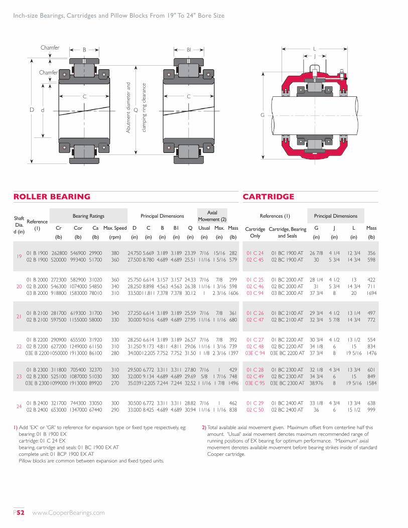
1) Add 'EX' or 'GR' to reference for expansion type or fixed type respectively, eg: bearing: 01 B 1900 EX cartridge: 01 C 24 EX bearing, cartridge and seals: 01 BC 1900 EX AT complete unit: 01 BCP 1900 EX AT Pillow blocks are common between expansion and fixed typed units.
2) Total available axial movement given. Maximum offset from centerline half this amount. 'Usual' axial movement denotes maximum recommended range of running positions of EX bearing for optimum performance. 'Maximum' axial movement denotes available movement before bearing strikes inside of standard Cooper cartridge.
Inch-size Bearings, Cartridges and Pillow Blocks From 19" To 24" Bore Size
Shaft Dia.
d (in)
Reference (1)
Bearing Ratings Principal DimensionsAxial
Movement (2)
Cr Cor Ca Max. Speed D C B B1 Q Usual Max. Mass
(lb) (lb) (lb) (rpm) (in) (in) (in) (in) (in) (in) (in) (lb)
19 01 B 1900 02 B 1900
262800 520000
546900 993400
29900 51700
380 360
24.750 27.500
5.669 8.780
3.189 4.689
3.189 4.689
23.39 25.51
7/16 11/16
15/16 1 5/16
282 579
2001 B 2000 02 B 2000 03 B 2000
272300 546300 918800
582900 1074000 1583000
31020 54850 78010
360 340 310
25.750 28.250 33.500
6.614 8.898 11.811
3.157 4.563 7.378
3.157 4.563 7.378
24.33 26.38 30.12
7/16 11/16
1
7/8 1 3/16 2 3/16
299 598 1606
21 01 B 2100 02 B 2100
281700 597500
619300 1155000
31700 58000
340 330
27.250 30.000
6.614 9.016
3.189 4.689
3.189 4.689
25.59 27.95
7/16 11/16
7/8 1 1/16
361 680
2201 B 2200 02 B 2200 03E B 2200
290900 627200 1050000
655500 1249000 1913000
31920 61150 86100
330 310 280
28.250 31.250 34.000
6.614 9.173 12.205
3.189 4.811 7.752
3.189 4.811 7.752
26.57 29.06 31.50
7/16 11/16 1 1/8
7/8 1 3/16 2 3/16
392 739 1397
2301 B 2300 02 B 2300 03E B 2300
311800 525100 1099000
705400 1087000 1913000
32370 51030 89920
310 300 270
29.500 32.000 35.039
6.772 9.134 12.205
3.311 4.689 7.244
3.311 4.689 7.244
27.80 29.69 32.52
7/16 5/8
1 1/16
1 1 7/16 1 7/8
429 748 1496
24 01 B 2400 02 B 2400
321700 653000
744300 1347000
33050 67440
300 290
30.500 33.000
6.772 8.425
3.311 4.689
3.311 4.689
28.82 30.94
7/16 11/16
1 1 1/16
462 838
ROLLER BEARING
References (1) Principal Dimensions
Cartridge Only
Cartridge, Bearing and Seals
G J L Mass
(in) (in) (in) (lb)
01 C 24 02 C 45
01 BC 1900 AT 02 BC 1900 AT
26 7/8 30
4 1/4 5 3/4
12 3/4 14 3/4
356 598
01 C 25 02 C 46 03 C 94
01 BC 2000 AT 02 BC 2000 AT 03 BC 2000 AT
28 1/4 31
37 3/4
4 1/2 5 3/4
8
13 14 3/4
20
422 711 1694
01 C 26 02 C 47
01 BC 2100 AT 02 BC 2100 AT
29 3/4 32 3/4
4 1/2 5 7/8
13 1/4 14 3/4
497 772
01 C 27 02 C 48 03E C 94
01 BC 2200 AT 02 BC 2200 AT 03E BC 2200 AT
30 3/4 34 1/8 37 3/4
4 1/2 6 8
13 1/2 15
19 5/16
554 834 1476
01 C 28 02 C 49 03E C 95
01 BC 2300 AT 02 BC 2300 AT 03E BC 2300 AT
32 1/8 34 3/4 38.976
4 3/4 6 8
13 3/4 15
19 5/16
601 849 1584
01 C 29 02 C 50
01 BC 2400 AT 02 BC 2400 AT
33 1/8 36
4 3/4 6
13 3/4 15 1/2
638 999
CARTRIDGE
G
LJ
B
D d
Chamfer
Chamfer
BI
C
Q
Abut
men
t diam
eter
and
clam
ping
ring
clea
ranc
e
C
P52 www.CooperBearings.com

3) Maximum fillet radii of abutments: inner race: 3/32" outer race: 5/64"
Inch-size Bearings, Cartridges and Pillow Blocks From 19" To 24" Bore Size
RN
O S
T
H
P
T
H
P
R RoN
O S
Ro
4 BOLT 8 BOLT
PILLOW BLOCK
References (1) R Bolts Mass (lb) Shaft Diameter
d (in)Pillow Block Complete H Min. Max. Ro S
No.Metric Size
Inch Size
N O P T Pillow Block Complete
Only Unit (in) (in) (in) (in) (in) (in) (in) (in) (in) Only Unit
P24 P45
01 BCP 1900 AT 02 BCP 1900 AT
19 21 3/4
31 5/16 31 3/16
32 15/16 32 3/4
- 4 1/2
7 3/8 11
4 8
M42 M36
1 3/4" 1 1/2"
43 50
12 14 1/2
2 7/8 3
38 43 11/16
884 1518
1522 2695 19
P25 P46 P94
01 BCP 2000 AT 02 BCP 2000 AT 03 BCP 2000 AT
19 1/4 22 1/2 24 1/2
32 7/16 32 7/16
36
34 34
38 1/16
- 4 1/2 6 1/2
8 1/2 11
9 1/2
4 8 8
M42 M36 M56
1 3/4" 1 1/2" 2 1/4"
43 51 63
12 14 1/2
16
3 3 1/8
4
38 9/16 45 1/16 52 3/4
884 1489 2200
1606 2798 5500
20
P26 P47
01 BCP 2100 AT 02 BCP 2100 AT
21 23 1/4
34 13/16 34 1/4
36 3/8 35 13/16
- 4 1/2
8 1/2 11
4 8
M42 M36
1 3/4" 1 1/2"
47 55 1/16
12 14 1/2
3 1/8 3 1/4
41 15/16 46 7/16
1089 1991
1947 3443 21
P27 P48 P94
01 BCP 2200 AT 02 BCP 2200 AT 03E BCP 2200 AT
23 1/4 24 1/4 24 1/2
36 1/16 35 9/16
36
37 5/8 37 5/8 38 1/16
- 4 1/2 6 1/2
8 1/8 11
9 1/2
4 8 8
M42 M42 M36
1 3/4" 1 3/4" 2 1/4"
48 1/16 56 63
12 15 16
3 1/4 3 3/8
4
43 11/16 48 7/16 52 3/4
1254 2123 2200
2200 3696 5073
22
P28 P49 P95
01 BCP 2300 AT 02 BCP 2300 AT 03E BCP 2300 AT
22 3/4 25
24 1/2
33 3/4 36 11/16
36
35 1/4 38 3/4 38 1/16
4 4 1/2 6 1/2
8 11/16 11
9 1/2
8 8 8
M36 M42 M56
1 1/2" 1 3/4" 2 1/4"
53 57 63
12 15 16
3 9/16 3 9/16
4
45 1/2 50
52 3/4
1386 2200 2046
2416 3797 5126
23
P29 P50
01 BCP 2400 AT 02 BCP 2400 AT
23 1/2 26 1/2
34 15/16 38 3/4
36 9/16 40 13/16
4 1/8 4 1/2
8 11/16 11
8 8
M36 M42
1 1/2" 1 3/4"
54 60
12 15
3 9/16 3 5/8
47 1/4 52 15/16
1386 2310
2486 4147 24
www.CooperBearings.com P53
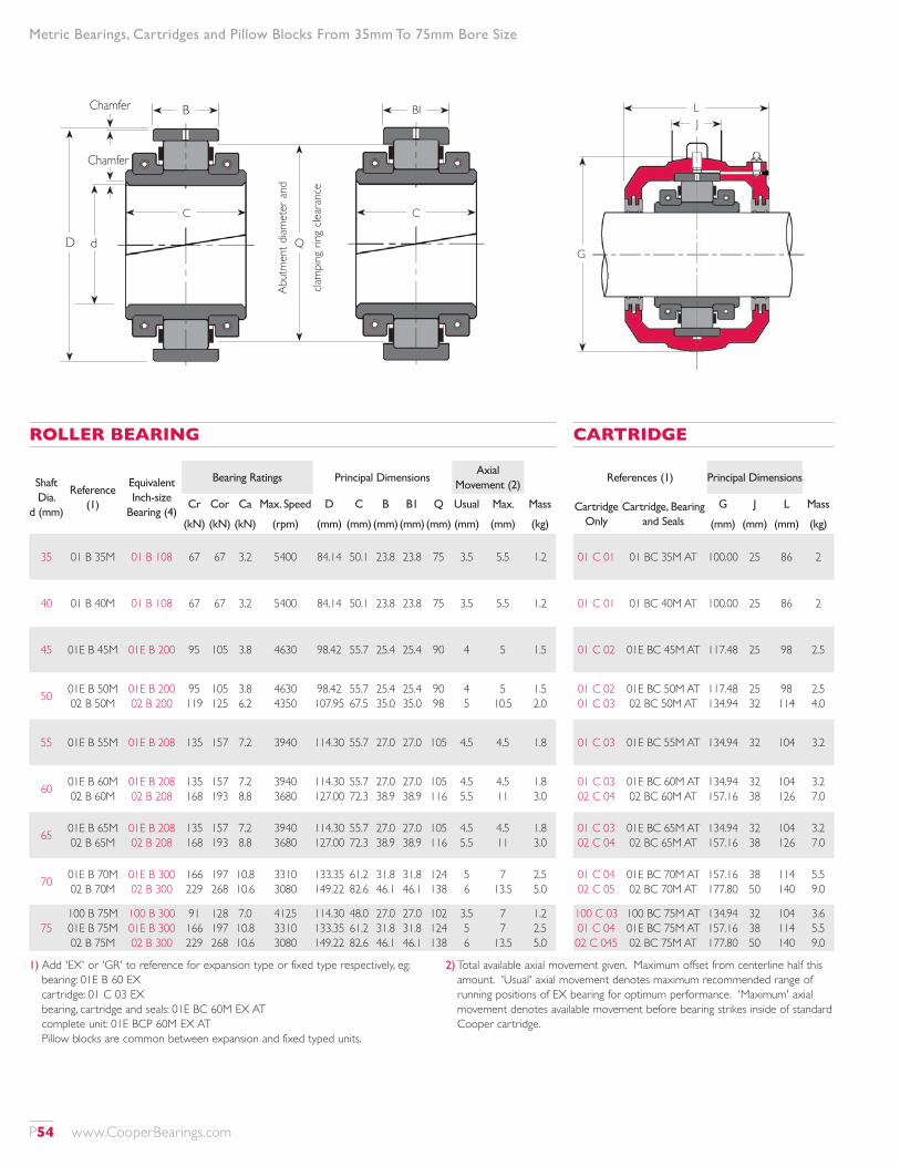
Metric Bearings, Cartridges and Pillow Blocks From 35mm To 75mm Bore Size
Shaft Dia.
d (mm)
Reference (1)
Equivalent Inch-size
Bearing (4)
Bearing Ratings Principal DimensionsAxial
Movement (2)
Cr Cor Ca Max. Speed D C B B1 Q Usual Max. Mass
(kN) (kN) (kN) (rpm) (mm) (mm) (mm)(mm)(mm) (mm) (mm) (kg)
35 01 B 35M 01 B 108 67 67 3.2 5400 84.14 50.1 23.8 23.8 75 3.5 5.5 1.2
40 01 B 40M 01 B 108 67 67 3.2 5400 84.14 50.1 23.8 23.8 75 3.5 5.5 1.2
45 01E B 45M 01E B 200 95 105 3.8 4630 98.42 55.7 25.4 25.4 90 4 5 1.5
50 01E B 50M 02 B 50M
01E B 200 02 B 200
95 119
105 125
3.8 6.2
4630 4350
98.42 107.95
55.7 67.5
25.4 35.0
25.4 35.0
90 98
4 5
5 10.5
1.5 2.0
55 01E B 55M 01E B 208 135 157 7.2 3940 114.30 55.7 27.0 27.0 105 4.5 4.5 1.8
60 01E B 60M 02 B 60M
01E B 208 02 B 208
135 168
157 193
7.2 8.8
3940 3680
114.30 127.00
55.7 72.3
27.0 38.9
27.0 38.9
105 116
4.5 5.5
4.5 11
1.8 3.0
65 01E B 65M 02 B 65M
01E B 208 02 B 208
135 168
157 193
7.2 8.8
3940 3680
114.30 127.00
55.7 72.3
27.0 38.9
27.0 38.9
105 116
4.5 5.5
4.5 11
1.8 3.0
70 01E B 70M 02 B 70M
01E B 300 02 B 300
166 229
197 268
10.8 10.6
3310 3080
133.35 149.22
61.2 82.6
31.8 46.1
31.8 46.1
124 138
5 6
7 13.5
2.5 5.0
75100 B 75M 01E B 75M 02 B 75M
100 B 300 01E B 300 02 B 300
91 166 229
128 197 268
7.0 10.8 10.6
4125 3310 3080
114.30 133.35 149.22
48.0 61.2 82.6
27.0 31.8 46.1
27.0 31.8 46.1
102 124 138
3.5 5 6
7 7
13.5
1.2 2.5 5.0
ROLLER BEARING
References (1) Principal Dimensions
Cartridge Only
Cartridge, Bearing and Seals
G J L Mass
(mm) (mm) (mm) (kg)
01 C 01 01 BC 35M AT 100.00 25 86 2
01 C 01 01 BC 40M AT 100.00 25 86 2
01 C 02 01E BC 45M AT 117.48 25 98 2.5
01 C 02 01 C 03
01E BC 50M AT 02 BC 50M AT
117.48 134.94
25 32
98 114
2.5 4.0
01 C 03 01E BC 55M AT 134.94 32 104 3.2
01 C 03 02 C 04
01E BC 60M AT 02 BC 60M AT
134.94 157.16
32 38
104 126
3.2 7.0
01 C 03 02 C 04
01E BC 65M AT 02 BC 65M AT
134.94 157.16
32 38
104 126
3.2 7.0
01 C 04 02 C 05
01E BC 70M AT 02 BC 70M AT
157.16 177.80
38 50
114 140
5.5 9.0
100 C 03 01 C 04 02 C 045
100 BC 75M AT 01E BC 75M AT 02 BC 75M AT
134.94 157.16 177.80
32 38 50
104 114 140
3.6 5.5 9.0
CARTRIDGE
1) Add 'EX' or 'GR' to reference for expansion type or fixed type respectively, eg: bearing: 01E B 60 EX cartridge: 01 C 03 EX bearing, cartridge and seals: 01E BC 60M EX AT complete unit: 01E BCP 60M EX AT Pillow blocks are common between expansion and fixed typed units.
2) Total available axial movement given. Maximum offset from centerline half this amount. 'Usual' axial movement denotes maximum recommended range of running positions of EX bearing for optimum performance. 'Maximum' axial movement denotes available movement before bearing strikes inside of standard Cooper cartridge.
G
LJ
B
D d
Chamfer
Chamfer
BI
C
Q
Abut
men
t diam
eter
and
clam
ping
ring
clea
ranc
e
C
P54 www.CooperBearings.com
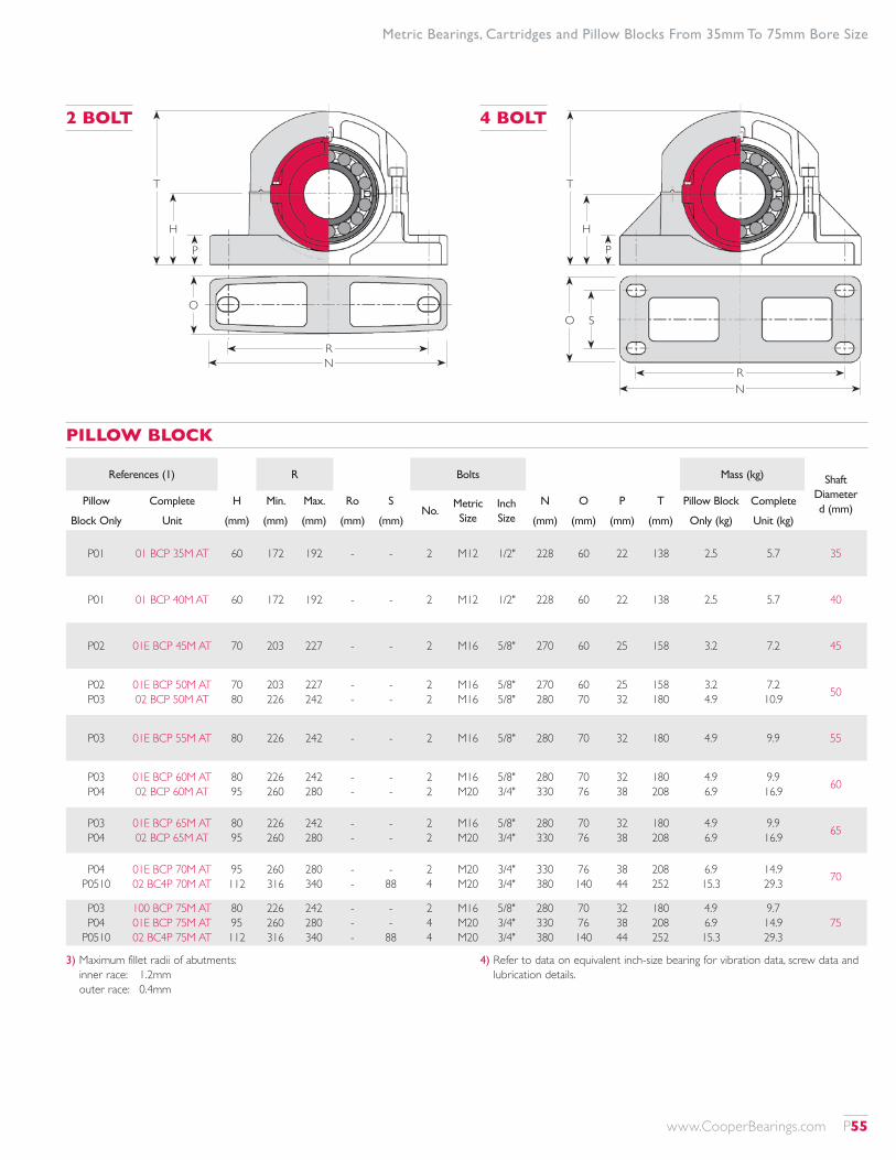
Metric Bearings, Cartridges and Pillow Blocks From 35mm To 75mm Bore Size
2 BOLT 4 BOLT
T
H
P
RN
O S
T
H
P
RN
O
References (1) R Bolts Mass (kg) Shaft Diameter d (mm)
Pillow Complete H Min. Max. Ro SNo.
Metric Size
Inch Size
N O P T Pillow Block Complete
Block Only Unit (mm) (mm) (mm) (mm) (mm) (mm) (mm) (mm) (mm) Only (kg) Unit (kg)
P01 01 BCP 35M AT 60 172 192 - - 2 M12 1/2" 228 60 22 138 2.5 5.7 35
P01 01 BCP 40M AT 60 172 192 - - 2 M12 1/2" 228 60 22 138 2.5 5.7 40
P02 01E BCP 45M AT 70 203 227 - - 2 M16 5/8" 270 60 25 158 3.2 7.2 45
P02 P03
01E BCP 50M AT 02 BCP 50M AT
70 80
203 226
227 242
- -
- -
2 2
M16 M16
5/8" 5/8"
270 280
60 70
25 32
158 180
3.2 4.9
7.2 10.9 50
P03 01E BCP 55M AT 80 226 242 - - 2 M16 5/8" 280 70 32 180 4.9 9.9 55
P03 P04
01E BCP 60M AT 02 BCP 60M AT
80 95
226 260
242 280
- -
- -
2 2
M16 M20
5/8" 3/4"
280 330
70 76
32 38
180 208
4.9 6.9
9.9 16.9 60
P03 P04
01E BCP 65M AT 02 BCP 65M AT
80 95
226 260
242 280
- -
- -
2 2
M16 M20
5/8" 3/4"
280 330
70 76
32 38
180 208
4.9 6.9
9.9 16.9 65
P04 P0510
01E BCP 70M AT 02 BC4P 70M AT
95 112
260 316
280 340
- -
- 88
2 4
M20 M20
3/4" 3/4"
330 380
76 140
38 44
208 252
6.9 15.3
14.9 29.3 70
P03 P04
P0510
100 BCP 75M AT 01E BCP 75M AT 02 BC4P 75M AT
80 95 112
226 260 316
242 280 340
- - -
- -
88
2 4 4
M16 M20 M20
5/8" 3/4" 3/4"
280 330 380
70 76 140
32 38 44
180 208 252
4.9 6.9 15.3
9.7 14.9 29.3
75
PILLOW BLOCK
3) Maximum fillet radii of abutments: inner race: 1.2mm outer race: 0.4mm
4) Refer to data on equivalent inch-size bearing for vibration data, screw data and lubrication details.
www.CooperBearings.com P55
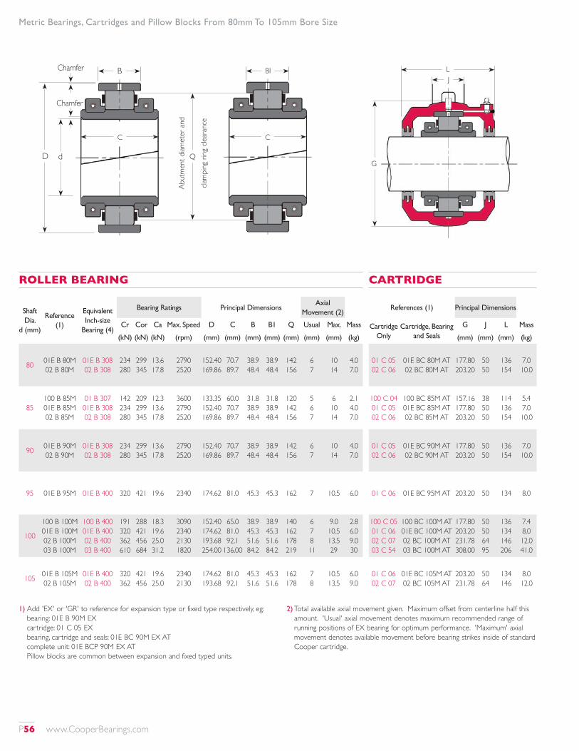
Shaft Dia.
d (mm)
Reference (1)
Equivalent Inch-size
Bearing (4)
Bearing Ratings Principal DimensionsAxial
Movement (2)
Cr Cor Ca Max. Speed D C B B1 Q Usual Max. Mass
(kN) (kN) (kN) (rpm) (mm) (mm) (mm) (mm) (mm) (mm) (mm) (kg)
80 01E B 80M 02 B 80M
01E B 308 02 B 308
234 280
299 345
13.6 17.8
2790 2520
152.40 169.86
70.7 89.7
38.9 48.4
38.9 48.4
142 156
6 7
10 14
4.0 7.0
85100 B 85M 01E B 85M 02 B 85M
01 B 307 01E B 308 02 B 308
142 234 280
209 299 345
12.3 13.6 17.8
3600 2790 2520
133.35 152.40 169.86
60.0 70.7 89.7
31.8 38.9 48.4
31.8 38.9 48.4
120 142 156
5 6 7
6 10 14
2.1 4.0 7.0
90 01E B 90M 02 B 90M
01E B 308 02 B 308
234 280
299 345
13.6 17.8
2790 2520
152.40 169.86
70.7 89.7
38.9 48.4
38.9 48.4
142 156
6 7
10 14
4.0 7.0
95 01E B 95M 01E B 400 320 421 19.6 2340 174.62 81.0 45.3 45.3 162 7 10.5 6.0
100
100 B 100M 01E B 100M 02 B 100M 03 B 100M
100 B 400 01E B 400 02 B 400 03 B 400
191 320 362 610
288 421 456 684
18.3 19.6 25.0 31.2
3090 2340 2130 1820
152.40 174.62 193.68 254.00
65.0 81.0 92.1
136.00
38.9 45.3 51.6 84.2
38.9 45.3 51.6 84.2
140 162 178 219
6 7 8 11
9.0 10.5 13.5 29
2.8 6.0 9.0 30
105 01E B 105M 02 B 105M
01E B 400 02 B 400
320 362
421 456
19.6 25.0
2340 2130
174.62 193.68
81.0 92.1
45.3 51.6
45.3 51.6
162 178
7 8
10.5 13.5
6.0 9.0
ROLLER BEARING
References (1) Principal Dimensions
Cartridge Only
Cartridge, Bearing and Seals
G J L Mass
(mm) (mm) (mm) (kg)
01 C 05 02 C 06
01E BC 80M AT 02 BC 80M AT
177.80 203.20
50 50
136 154
7.0 10.0
100 C 04 01 C 05 02 C 06
100 BC 85M AT 01E BC 85M AT 02 BC 85M AT
157.16 177.80 203.20
38 50 50
114 136 154
5.4 7.0 10.0
01 C 05 02 C 06
01E BC 90M AT 02 BC 90M AT
177.80 203.20
50 50
136 154
7.0 10.0
01 C 06 01E BC 95M AT 203.20 50 134 8.0
100 C 05 01 C 06 02 C 07 03 C 54
100 BC 100M AT 01E BC 100M AT 02 BC 100M AT 03 BC 100M AT
177.80 203.20 231.78 308.00
50 50 64 95
136 134 146 206
7.4 8.0 12.0 41.0
01 C 06 02 C 07
01E BC 105M AT 02 BC 105M AT
203.20 231.78
50 64
134 146
8.0 12.0
CARTRIDGE
1) Add 'EX' or 'GR' to reference for expansion type or fixed type respectively, eg: bearing: 01E B 90M EX cartridge: 01 C 05 EX bearing, cartridge and seals: 01E BC 90M EX AT complete unit: 01E BCP 90M EX AT Pillow blocks are common between expansion and fixed typed units.
2) Total available axial movement given. Maximum offset from centerline half this amount. 'Usual' axial movement denotes maximum recommended range of running positions of EX bearing for optimum performance. 'Maximum' axial movement denotes available movement before bearing strikes inside of standard Cooper cartridge.
Metric Bearings, Cartridges and Pillow Blocks From 80mm To 105mm Bore Size
G
LJ
B
D d
Chamfer
Chamfer
BI
C
Q
Abut
men
t diam
eter
and
clam
ping
ring
clea
ranc
e
C
P56 www.CooperBearings.com
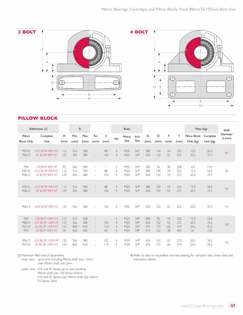
2 BOLT 4 BOLT
T
H
P
RN
O S
T
H
P
RN
O
References (1) R Bolts Mass (kg) Shaft Diameter d (mm)
Pillow Complete H Min. Max. Ro SNo.
Metric Size
Inch Size
N O P T Pillow Block Complete
Block Only Unit (mm) (mm) (mm) (mm) (mm) (mm) (mm) (mm) (mm) Only (kg) Unit (kg)
P0510 P0613
01E BC4P 80M AT 02 BC4P 80M AT
112 125
316 356
340 380
- -
88 102
4 4
M20 M20
3/4" 3/4"
380 426
140 152
44 52
252 272
15.3 20.2
26.3 37.2 80
P04 P0510 P0613
100 BCP 85M AT 01E BC4P 85M AT 02 BC4P 85M AT
95 112 125
260 316 356
280 340 380
- - -
- 88 102
2 4 4
M20 M20 M20
3/4" 3/4" 3/4"
330 380 426
76 140 152
38 44 52
208 252 272
6.9 15.3 20.2
14.4 26.3 37.2
85
P0510 P0613
01E BC4P 90M AT 02 BC4P 90M AT
112 125
316 356
340 380
- -
88 102
4 4
M20 M20
3/4" 3/4"
380 426
140 152
44 52
252 272
15.3 20.2
26.3 37.2 90
P0613 01E BC4P 95M AT 125 356 380 - 102 4 M20 3/4" 426 152 52 272 20.2 37.2 95
P05 P0613 P0710 P54
100 BCP 100M AT 01E BC4P 100M AT 02 BC4P 100M AT 03 BCP 100M AT
112 125 143 191
312 356 400 426
328 380 424 450
- - - -
- 102 114 82
2 4 4 4
M24 M20 M20 M24
7/8" 3/4" 3/4" 7/8"
380 426 476 514
90 152 172 152
44 52 60 38
252 272 314 405
13.3 20.2 24.2 61
23.5 34.2 45.2 132
100
P0613 P0710
01E BC4P 105M AT 02 BC4P 105M AT
125 143
356 400
380 424
- -
102 114
4 4
M20 M20
3/4" 3/4"
426 476
152 172
52 60
272 314
20.2 24.2
34.2 45.2 105
PILLOW BLOCK
3) Maximum fillet radii of abutments: inner race: up to and including 90mm shaft size: 1.2mm
over 90mm shaft size: 2mm
outer race: 01E and 02 Series up to and including 90mm shaft size, 100 Series: 0.4mm 01E and 02 Series over 90mm shaft size: 0.8mm 03 Series: 2mm
4) Refer to data on equivalent inch-size bearing for vibration data, screw data and lubrication details.
Metric Bearings, Cartridges and Pillow Blocks From 80mm To 105mm Bore Size
www.CooperBearings.com P57

Shaft Dia.
d (mm)
Reference (1)
Equivalent Inch-size
Bearing (4)
Bearing Ratings Principal DimensionsAxial
Movement (2)
Cr Cor Ca Max. Speed D C B B1 Q Usual Max. Mass
(kN) (kN) (kN) (rpm) (mm) (mm) (mm) (mm) (mm) (mm) (mm) (kg)
110
100 B 110M 01 B 110M 02 B 110M 03 B 110M
100 B 408 01 B 408 02 B 408 03 B 408
279 306 454 614
426 407 583 698
22.2 18.6 31.2 39.2
2750 1970 1820 1640
174.62 203.20 228.60 266.70
80.0 84.9 100.0 147.0
45.3 46.9 57.2 87.3
45.3 46.9 57.2 87.3
160 182 202 232
7 7 9 11
9.5 12.5 13.5 30
4.6 10.2 16.0 36.0
115 01 B 115M 02 B 115M
01 B 408 02 B 408
306 454
407 583
18.6 31.2
1970 1820
203.20 228.60
84.9 100.0
46.9 57.2
46.9 57.2
182 202
7 9
12.5 13.5
10.2 16.0
120
100 B 120M 01 B 120M 02 B 120M 03 B 120M
100 B 500 01 B 500 02 B 500 03 B 500
280 355 547 614
433 484 713 698
23.8 22.2 38.2 39.2
2480 1740 1600 1640
203.20 222.25 254.00 266.70
85.0 89.7 114.3 147.0
46.9 54.0 63.5 87.3
46.9 54.0 63.5 87.3
180 200 224 232
7 7 10 11
11 15 15 30
7.4 12.8 20.0 36.0
125 01 B 125M 02 B 125M
01 B 500 02 B 500
355 547
484 713
22.2 38.2
1740 1600
222.25 254.00
89.7 114.3
54.0 63.5
54.0 63.5
200 224
7 10
15 15
12.8 20.0
130
100 B 130M 01 B 130M 02 B 130M 03 B 130M
100 B 500 01 B 500 02 B 500 03 B 500
280 355 547 706
433 484 713 852
23.8 22.2 38.2 49.0
2480 1740 1600 1500
203.20 222.25 254.00 279.40
85.0 89.7 114.3 140.0
46.9 54.0 63.5 73.1
46.9 54.0 63.5 84.2
180 200 224 245
7 7 10 11
11 15 15 18
7.4 12.8 20.0 36.0
ROLLER BEARING
References (1) Principal Dimensions
Cartridge Only
Cartridge, Bearing and Seals
G J L Mass
(mm) (mm) (mm) (kg)
100 C 06 01 C 07 02 C 08 03 C 55
100 BC 110M AT 01 BC 110M AT 02 BC 110M AT 03 BC 110M AT
203.20 231.78 266.70 323.85
50 64 76 102
134 142 162 222
7.9 11.9 19.0 46.0
01 C 07 02 C 08
01 BC 115M AT 02 BC 115M AT
231.78 266.70
64 76
142 162
11.9 19.0
100 C 07 01 C 08 02 C 10 03 C 55
100 BC 120M AT 01 BC 120M AT 02 BC 120M AT 03 BC 120M AT
231.78 266.70 295.28 323.85
64 76 82 102
142 156 184 222
11.9 19.0 26.0 46.0
01 C 08 02 C 10
01 BC 125M AT 02 BC 125M AT
266.70 295.28
76 82
156 184
19.5 26.0
100 C 07 01 C 08 02 C 10 03 C 56
100 BC 130M AT 01 BC 130M AT 02 BC 130M AT 03 BC 130M AT
231.78 266.70 295.28 323.85
64 76 82 102
142 156 184 222
11.9 19.0 26.0 48.0
CARTRIDGE
Metric Bearings, Cartridges and Pillow Blocks From 110mm To 130mm Bore Size
1) Add 'EX' or 'GR' to reference for expansion type or fixed type respectively, eg: bearing: 01E B 120M EX cartridge: 01 C 08 EX bearing, cartridge and seals: 01E BC 120M EX AT complete unit: 01E BCP 120M EX AT Pillow blocks are common between expansion and fixed typed units.
2) Total available axial movement given. Maximum offset from centerline half this amount. 'Usual' axial movement denotes maximum recommended range of running positions of EX bearing for optimum performance. 'Maximum' axial movement denotes available movement before bearing strikes inside of standard Cooper cartridge.
G
LJ
B
D d
Chamfer
Chamfer
BI
C
Q
Abut
men
t diam
eter
and
clam
ping
ring
clea
ranc
e
C
P58 www.CooperBearings.com
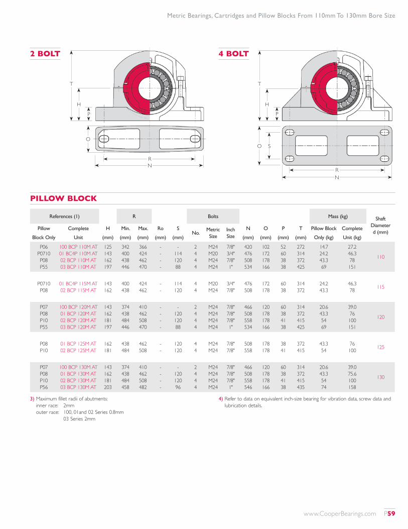
2 BOLT 4 BOLT
T
H
P
RN
O S
T
H
P
RN
O
References (1) R Bolts Mass (kg) Shaft Diameter d (mm)
Pillow Complete H Min. Max. Ro SNo.
Metric Size
Inch Size
N O P T Pillow Block Complete
Block Only Unit (mm) (mm) (mm) (mm) (mm) (mm) (mm) (mm) (mm) Only (kg) Unit (kg)
P06 P0710 P08 P55
100 BCP 110M AT 01 BC4P 110M AT 02 BCP 110M AT 03 BCP 110M AT
125 143 162 197
342 400 438 446
366 424 462 470
- - - -
- 114 120 88
2 4 4 4
M24 M20 M24 M24
7/8" 3/4" 7/8" 1"
420 476 508 534
102 172 178 166
52 60 38 38
272 314 372 425
14.7 24.2 43.3 69
27.2 46.3 78 151
110
P0710 P08
01 BC4P 115M AT 02 BCP 115M AT
143 162
400 438
424 462
- -
114 120
4 4
M20 M24
3/4" 7/8"
476 508
172 178
60 38
314 372
24.2 43.3
46.3 78 115
P07 P08 P10 P55
100 BCP 120M AT 01 BCP 120M AT 02 BCP 120M AT 03 BCP 120M AT
143 162 181 197
374 438 484 446
410 462 508 470
- - - -
- 120 120 88
2 4 4 4
M24 M24 M24 M24
7/8" 7/8" 7/8" 1"
466 508 558 534
120 178 178 166
60 38 41 38
314 372 415 425
20.6 43.3 54 69
39.0 76 100 151
120
P08 P10
01 BCP 125M AT 02 BCP 125M AT
162 181
438 484
462 508
- -
120 120
4 4
M24 M24
7/8" 7/8"
508 558
178 178
38 41
372 415
43.3 54
76 100 125
P07 P08 P10 P56
100 BCP 130M AT 01 BCP 130M AT 02 BCP 130M AT 03 BCP 130M AT
143 162 181 203
374 438 484 458
410 462 508 482
- - - -
- 120 120 96
2 4 4 4
M24 M24 M24 M24
7/8" 7/8" 7/8" 1"
466 508 558 546
120 178 178 166
60 38 41 38
314 372 415 435
20.6 43.3 54 74
39.0 75.6 100 158
130
PILLOW BLOCK
Metric Bearings, Cartridges and Pillow Blocks From 110mm To 130mm Bore Size
3) Maximum fillet radii of abutments: inner race: 2mm outer race: 100, 01and 02 Series 0.8mm
03 Series 2mm
4) Refer to data on equivalent inch-size bearing for vibration data, screw data and lubrication details.
www.CooperBearings.com P59
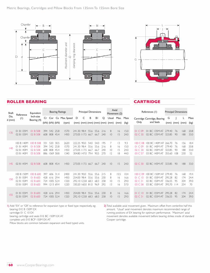
Shaft Dia.
d (mm)
Reference (1)
Equivalent Inch-size
Bearing (4)
Bearing Ratings Principal DimensionsAxial
Movement (2)
Cr Cor Ca Max. Speed D C B B1 Q Usual Max. Mass
(kN) (kN) (kN) (rpm) (mm) (mm) (mm) (mm) (mm) (mm) (mm) (kg)
135 01 B 135M 02 B 135M
01 B 508 02 B 508
394 608
542 808
25.8 45.4
1570 1450
241.30 273.05
98.4 117.5
55.6 66.7
55.6 66.7
216 240
8 10
16 15
15.0 24.0
140
100 B 140M 01 B 140M 02 B 140M 03 B 140M
100 B 508 01 B 508 02 B 508 03 B 508
331 394 608 886
520 542 808 1069
30.5 25.8 45.4 58.8
2620 1570 1450 1340
222.25 241.30 273.05 304.80
90.0 98.4 117.5 147.0
54.0 55.6 66.7 79.4
54.0 55.6 66.7 90.5
195 216 240 270
7 8 10 12
13 16 15 18
9.3 15.0 24.0 44.0
145 02 B 145M 02 B 508 608 808 45.4 1450 273.05 117.5 66.7 66.7 240 10 15 24.0
150
100 B 150M 01 B 150M 02 B 150M 03 B 150M
100 B 600 01 B 600 02 B 600 03 B 600
397 428 724 994
606 616 1005 1213
31.4 29.4 52.4 69.4
2400 1450 1320 1220
241.30 254.00 292.10 330.20
90.0 98.4 123.8 160.0
55.6 55.6 68.3 81.0
55.6 55.6 68.3 96.9
215 230 258 292
8 8 10 13
15.5 16 15 16
10.4 16.6 29.0 57.0
155 01 B 155M 02 B 155M
01 B 600 02 B 600
428 724
616 1005
29.4 52.4
1450 1320
254.00 292.10
98.4 123.8
55.6 68.3
55.6 68.3
230 258
8 10
16 15
16.6 29.0
ROLLER BEARING
References (1) Principal Dimensions
Cartridge Only
Cartridge, Bearing and Seals
G J L Mass
(mm) (mm) (mm) (kg)
01 C 09 02 C 30
01 BC 135M AT 02 BC 135M AT
279.40 323.85
76 90
168 188
20.8 33.0
100 C 08 01 C 09 02 C 30 03 C 57
100 BC 140M AT 01 BC 140M AT 02 BC 140M AT 03 BC 140M AT
266.70 279.40 323.85 355.60
76 76 90 108
156 168 188 230
18.4 20.8 33.0 52
02 C 30 02 BC 145M AT 323.85 90 188 33.0
100 C 09 01 C 10 02 C 31 03 C 58
100 BC 150M AT 01 BC 150M AT 02 BC 150M AT 03 BC 150M AT
279.40 295.28 336.55 393.70
76 82 95 114
168 174 204 254
19.4 24.4 39.0 70
01 C 10 02 C 31
01 BC 155M AT 02 BC 155M AT
295.28 336.55
82 95
174 204
24.4 39.0
CARTRIDGE
Metric Bearings, Cartridges and Pillow Blocks From 135mm To 155mm Bore Size
1) Add 'EX' or 'GR' to reference for expansion type or fixed type respectively, eg: bearing: 01E B 150M EX cartridge: 01 C 10 EX bearing, cartridge and seals: 01E BC 150M EX AT complete unit: 01E BCP 150M EX AT Pillow blocks are common between expansion and fixed typed units.
2) Total available axial movement given. Maximum offset from centerline half this amount. 'Usual' axial movement denotes maximum recommended range of running positions of EX bearing for optimum performance. 'Maximum' axial movement denotes available movement before bearing strikes inside of standard Cooper cartridge.
G
LJ
B
D d
Chamfer
Chamfer
BI
C
Q
Abut
men
t diam
eter
and
clam
ping
ring
clea
ranc
e
C
P60 www.CooperBearings.com

References (1) R Bolts Mass (kg) Shaft Diameter d (mm)
Pillow Complete H Min. Max. Ro SNo.
Metric Size
Inch Size
N O P T Pillow Block Complete
Block Only Unit (mm) (mm) (mm) (mm) (mm) (mm) (mm) (mm) (mm) Only (kg) Unit (kg)
P09 P30
01 BCP 135M AT 02 BCP 135M AT
181 203
470 534
494 558
- -
120 120
4 4
M24 M24
7/8" 1"
558 610
178 178
41 51
405 460
52 76
88 133 135
P08 P09 P30 P57
100 BCP 140M AT 01 BCP 140M AT 02 BCP 140M AT 03 BCP 140M AT
162 181 203 229
438 470 534 494
462 494 558 534
- - - -
120 120 120 120
4 4 4 4
M24 M24 M24 M30
7/8" 7/8" 1"
1 1/4"
508 558 610 622
178 178 178 178
38 41 51 54
372 405 460 485
43.3 52 76 97
71 88 133 193
140
P30 02 BCP 145M AT 203 534 558 - 120 4 M24 1" 610 178 51 460 76 133 145
P09 P10 P31 P58
100 BCP 150M AT 01 BCP 150M AT 02 BCP 150M AT 03 BCP 150M AT
181 181 210 254
470 484 546 538
494 508 570 578
-- - -
120 120 128 120
4 4 4 4
M24 M24 M24 M30
7/8" 7/8" 1"
1 1/4"
558 558 636 666
178 178 204 204
41 41 50 57
405 415 470 535
52 54 83 142
82 95 151 269
150
P10 P31
01 BCP 155M AT 02 BCP 155M AT
181 210
484 546
508 570
- -
120 128
4 4
M24 M24
7/8" 1"
558 636
178 204
41 50
415 470
54 83
95 151 155
PILLOW BLOCK
Metric Bearings, Cartridges and Pillow Blocks From 135mm To 155mm Bore Size
3) Maximum fillet radii of abutments: inner race: 2mm outer race: 100, 01and 02 Series 0.8mm
03 Series 2mm
4) Refer to data on equivalent inch-size bearing for vibration data, screw data and lubrication details.
T
H
P
R
N
O S
www.CooperBearings.com P61

Shaft Dia.
d (mm)
Reference (1)
Equivalent Inch-size
Bearing (4)
Bearing Ratings Principal DimensionsAxial
Movement (2)
Cr Cor Ca Max. Speed D C B B1 Q Usual Max. Mass
(kN) (kN) (kN) (rpm) (mm) (mm) (mm) (mm) (mm) (mm) (mm) (kg)
160
01 B 600-160M 01E B 160M
02 B 600-160M 02E B 160M 03 B 160M
01 B 600 01 B 608 02 B 600 02 B 608 03 B 608
428 594 724 887 1156
616 863 1005 1262 1564
29.4 56.5 52.4 71.2 79.2
1450 1320 1320 1200 1110
254.00 273.05 292.10 317.50 355.60
98.4 109.0 123.8 140.0 171.0
55.6 60.3 68.3 83.3 103.2
55.6 60.3 68.3 83.3 103.2
230 248 258 280 308
8 8 10 11 14
16 18 15 25 31
16.6 21.0 29.0 39.0 72.0
170
01E B 608-170M 01E B 170M 02E B 170M 03 B 170M
01 B 608 01 B 700 02 B 608 03 B 700
594 557 887 1156
863 845 1262 1564
56.5 52.2 71.2 79.2
1320 1220 1200 1110
273.05 285.75 317.50 355.60
109.0 109.0 140.0 171.0
60.3 55.5 83.3 103.2
60.3 55.5 83.3 103.2
248 260 280 308
8 8 11 14
18 13.5 25 31
21.0 23.0 39.0 72.0
17501E B 175M 02E B 175M
01 B 700 02 B 700
557 936
845 1334
52.2 82.8
1220 1120
285.75 330.20
109.0 140.0
55.5 83.3
55.5 83.3
260 294
8 11
13.5 25
23.0 45.0
18001E B 180M 02E B 180M 03 B 180M
01 B 700 02 B 700 03 B 700
557 936 1242
845 1334 1704
52.2 82.8 89.0
1220 1120 1030
285.75 330.20 374.65
109.0 140.0 178.0
55.5 83.3 92.1
55.5 83.3 108.8
260 294 326
8 11 15
13.5 25 16
23.0 45.0 79.0
19001E B 190M 02E B 190M 03 B 190M
01 B 800 02 B 800 03 B 800
679 1137 1451
1078 1627 2022
72.5 122.0 99.6
1070 960 880
311.15 368.30 419.10
109.0 156.0 191.0
60.3 90.5 97.7
60.3 90.5 118.3
285 328 366
8 13 16
18 26 16
25.0 59.0 105
ROLLER BEARING
References (1) Principal Dimensions
Cartridge Only
Cartridge, Bearing and Seals
G J L Mass
(mm) (mm) (mm) (kg)
01 C 10 OTL 01 C 11
02 C 31 OTL 02 C 32 03 C 59
01 BC 600-160M AT 01E BC 160M AT
02 BC 600-160M AT 02E BC 160M AT 03 BC 160M AT
295.28 311.15 336.55 368.30 422.30
82 76 95 95 120
174 192 204 232 268
24.4 30.0 39.0 56 81
01 C 11 OTL 01 C 12
02 C 32 OTL 03 C 59
01E BC 608-170M AT 01E BC 170M AT 02E BC 170M AT 03 BC 170M AT
311.15 323.85 368.30 422.30
76 70 95 120
192 200 232 268
30.0 31.0 56 81
01 C 12 02 C 33
01E BC 175M AT 02E BC 175M AT
323.85 381.00
70 95
200 242
31.0 66
01 C 12 02 C 33 03 C 60
01E BC 180M AT 02E BC 180M AT 03 BC 180M AT
323.85 381.00 431.80
70 95 132
200 242 284
31.0 66 87
01 C 13 02 C 34 03 C 61
01E BC 190M AT 02E BC 190M AT 03 BC 190M AT
358.78 425.50 489.00
86 105 146
200 258 300
41.0 84 109
CARTRIDGE
1) Add 'EX' or 'GR' to reference for expansion type or fixed type respectively, eg: bearing: 01E B 175M EX cartridge: 01 C 12 EX bearing, cartridge and seals: 01E BC 175M EX AT complete unit: 01E BCP 175M EX AT Pillow blocks are common between expansion and fixed typed units.
2) Total available axial movement given. Maximum offset from centerline half this amount. 'Usual' axial movement denotes maximum recommended range of running positions of EX bearing for optimum performance. 'Maximum' axial movement denotes available movement before bearing strikes inside of standard Cooper cartridge.
Metric Bearings, Cartridges and Pillow Blocks From 160mm To 190mm Bore Size
G
LJ
B
D d
Chamfer
Chamfer
BI
C
Q
Abut
men
t diam
eter
and
clam
ping
ring
clea
ranc
e
C
P62 www.CooperBearings.com
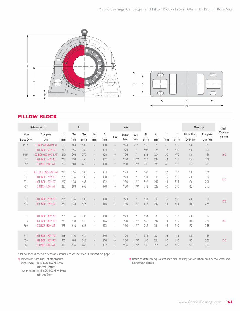
References (1) R Bolts Mass (kg) Shaft Diameter d (mm)
Pillow Complete H Min. Max. Ro SNo.
Metric Size
Inch Size
N O P T Pillow Block Complete
Block Only Unit (mm) (mm) (mm) (mm) (mm) (mm) (mm) (mm) (mm) Only (kg) Unit (kg)
P10* P11 P31* P32 P59
01 BCP 600-160M AT 01E BCP 160M AT
02 BCP 600-160M AT 02E BCP 160M AT 03 BCP 160M AT
181 213 210 267 267
484 356 546 428 608
508 380 570 468 648
- - - - -
120 114 128 172 140
4 4 4 4 4
M24 M24 M24 M30 M30
7/8" 1" 1"
1 1/4" 1 1/4"
558 508 636 596 736
178 178 204 242 228
41 32 50 44 60
415 430 470 535 570
54 53 83 106 162
95 104 151 201 315
160
P11 P12 P32 P59
01E BCP 608-170M AT 01E BCP 170M AT 02E BCP 170M AT 03 BCP 170M AT
213 235 267 267
356 376 428 608
380 400 468 648
- - - -
114 128 172 140
4 4 4 4
M24 M24 M30 M30
1" 1"
1 1/4" 1 1/4"
508 534 596 736
178 190 242 228
32 35 44 60
430 470 535 570
53 63 106 162
104 117 201 315
170
P12 P33
01E BCP 175M AT 02E BCP 175M AT
235 273
376 438
400 478
- -
128 166
4 4
M24 M30
1" 1 1/4"
534 636
190 242
35 44
470 545
63 116
117 227
175
P12 P33 P60
01E BCP 180M AT 02E BCP 180M AT 03 BCP 180M AT
235 273 279
376 438 616
400 478 656
- - -
128 166 152
4 4 4
M24 M30 M30
1" 1 1/4" 1 1/4"
534 636 762
190 242 254
35 44 64
470 545 580
63 116 172
117 227 338
180
P13 P34 P61
01E BCP 190M AT 02E BCP 190M AT 03 BCP 190M AT
248 305 311
410 488 616
434 528 656
- - -
140 190 172
4 4 4
M24 M30 M36
1" 1 1/4" 1 1/2"
572 686 838
204 266 266
38 50 67
495 610 655
83 145 223
149 288 437
190
PILLOW BLOCK
3) Maximum fillet radii of abutments: inner race: 01B 600-160M: 2mm others: 2.3mm outer race: 01B 600-160M: 0.8mm others: 2mm
4) Refer to data on equivalent inch-size bearing for vibration data, screw data and lubrication details.
* Pillow blocks marked with an asterisk are of the style illustrated on page 61.
Metric Bearings, Cartridges and Pillow Blocks From 160mm To 190mm Bore Size
RN
O S
T
H
P
www.CooperBearings.com P63
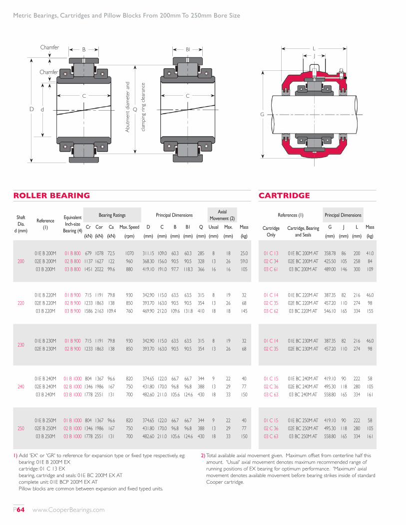
Shaft Dia.
d (mm)
Reference (1)
Equivalent Inch-size
Bearing (4)
Bearing Ratings Principal DimensionsAxial
Movement (2)
Cr Cor Ca Max. Speed D C B B1 Q Usual Max. Mass
(kN) (kN) (kN) (rpm) (mm) (mm) (mm) (mm) (mm) (mm) (mm) (kg)
20001E B 200M 02E B 200M 03 B 200M
01 B 800 02 B 800 03 B 800
679 1137 1451
1078 1627 2022
72.5 122 99.6
1070 960 880
311.15 368.30 419.10
109.0 156.0 191.0
60.3 90.5 97.7
60.3 90.5 118.3
285 328 366
8 13 16
18 26 16
25.0 59.0 105
22001E B 220M 02E B 220M 03 B 220M
01 B 900 02 B 900 03 B 900
715 1233 1586
1191 1863 2163
79.8 138
109.4
930 850 760
342.90 393.70 469.90
115.0 163.0 212.0
63.5 90.5 109.6
63.5 90.5 131.8
315 354 410
8 13 18
19 26 18
32 68 145
23001E B 230M 02E B 230M
01 B 900 02 B 900
715 1233
1191 1863
79.8 138
930 850
342.90 393.70
115.0 163.0
63.5 90.5
63.5 90.5
315 354
8 13
19 26
32 68
24001E B 240M 02E B 240M 03 B 240M
01 B 1000 02 B 1000 03 B 1000
804 1346 1778
1367 1986 2551
96.6 167 131
820 750 700
374.65 431.80 482.60
122.0 170.0 211.0
66.7 96.8 105.6
66.7 96.8 124.6
344 388 430
9 13 18
22 29 33
40 77 150
25001E B 250M 02E B 250M 03 B 250M
01 B 1000 02 B 1000 03 B 1000
804 1346 1778
1367 1986 2551
96.6 167 131
820 750 700
374.65 431.80 482.60
122.0 170.0 211.0
66.7 96.8 105.6
66.7 96.8 124.6
344 388 430
9 13 18
22 29 33
40 77 150
ROLLER BEARING
References (1) Principal Dimensions
Cartridge Only
Cartridge, Bearing and Seals
G J L Mass
(mm) (mm) (mm) (kg)
01 C 13 02 C 34 03 C 61
01E BC 200M AT 02E BC 200M AT 03 BC 200M AT
358.78 425.50 489.00
86 105 146
200 258 300
41.0 84 109
01 C 14 02 C 35 03 C 62
01E BC 220M AT 02E BC 220M AT 03 BC 220M AT
387.35 457.20 546.10
82 110 165
216 274 334
46.0 98 155
01 C 14 02 C 35
01E BC 230M AT 02E BC 230M AT
387.35 457.20
82 110
216 274
46.0 98
01 C 15 02 C 36 03 C 63
01E BC 240M AT 02E BC 240M AT 03 BC 240M AT
419.10 495.30 558.80
90 118 165
222 280 334
58 105 161
01 C 15 02 C 36 03 C 63
01E BC 250M AT 02E BC 250M AT 03 BC 250M AT
419.10 495.30 558.80
90 118 165
222 280 334
58 105 161
CARTRIDGE
1) Add 'EX' or 'GR' to reference for expansion type or fixed type respectively, eg: bearing: 01E B 200M EX cartridge: 01 C 13 EX bearing, cartridge and seals: 01E BC 200M EX AT complete unit: 01E BCP 200M EX AT Pillow blocks are common between expansion and fixed typed units.
2) Total available axial movement given. Maximum offset from centerline half this amount. 'Usual' axial movement denotes maximum recommended range of running positions of EX bearing for optimum performance. 'Maximum' axial movement denotes available movement before bearing strikes inside of standard Cooper cartridge.
Metric Bearings, Cartridges and Pillow Blocks From 200mm To 250mm Bore Size
G
LJ
B
D d
Chamfer
Chamfer
BI
C
Q
Abut
men
t diam
eter
and
clam
ping
ring
clea
ranc
e
C
P64 www.CooperBearings.com
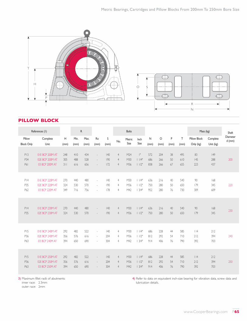
References (1) R Bolts Mass (kg) Shaft Diameter d (mm)
Pillow Complete H Min. Max. Ro SNo.
Metric Size
Inch Size
N O P T Pillow Block Complete
Block Only Unit (mm) (mm) (mm) (mm) (mm) (mm) (mm) (mm) (mm) Only (kg) Unit (kg)
P13 P34 P61
01E BCP 200M AT 02E BCP 200M AT 03 BCP 200M AT
248 305 311
410 488 616
434 528 656
- - -
140 190 172
4 4 4
M24 M30 M36
1" 1 1/4" 1 1/2"
572 686 838
204 266 266
38 50 67
495 610 655
83 145 223
149 288 437
200
P14 P35 P62
01E BCP 220M AT 02E BCP 220M AT 03 BCP 220M AT
270 324 349
440 530 716
480 570 756
- - -
140 190 178
4 4 4
M30 M36 M42
1 1/4" 1 1/2" 1 3/4"
636 750 952
216 280 280
40 50 76
540 650 730
90 179 309
168 345 609
220
P14 P35
01E BCP 230M AT 02E BCP 230M AT
270 324
440 530
480 570
- -
140 190
4 4
M30 M36
1 1/4" 1 1/2"
636 750
216 280
40 50
540 650
90 179
168 345
230
P15 P36 P63
01E BCP 240M AT 02E BCP 240M AT 03 BCP 240M AT
292 356 394
482 576 650
522 616 690
- - -
140 204 304
4 4 4
M30 M36 M42
1 1/4" 1 1/2" 1 3/4"
686 812 914
228 292 406
44 54 76
585 710 790
114 212 392
212 394 703
240
P15 P36 P63
01E BCP 250M AT 02E BCP 250M AT 03 BCP 250M AT
292 356 394
482 576 650
522 616 690
- - -
140 204 304
4 4 4
M30 M36 M42
1 1/4" 1 1/2" 1 3/4"
686 812 914
228 292 406
44 54 76
585 710 790
114 212 392
212 394 703
250
PILLOW BLOCK
3) Maximum fillet radii of abutments: inner race: 2.3mm outer race: 2mm
4) Refer to data on equivalent inch-size bearing for vibration data, screw data and lubrication details.
RN
O S
T
H
P
Metric Bearings, Cartridges and Pillow Blocks From 200mm To 250mm Bore Size
www.CooperBearings.com P65
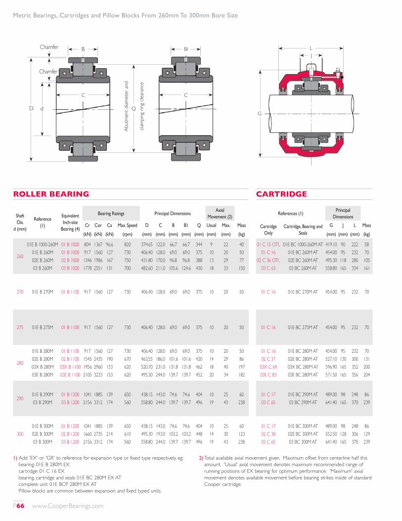
Shaft Dia.
d (mm)
Reference (1)
Equivalent Inch-size
Bearing (4)
Bearing Ratings Principal DimensionsAxial
Movement (2)
Cr Cor Ca Max. Speed D C B B1 Q Usual Max. Mass
(kN) (kN) (kN) (rpm) (mm) (mm) (mm) (mm) (mm) (mm) (mm) (kg)
260
01E B 1000-260M 01E B 260M 02E B 260M 03 B 260M
01 B 1000 01 B 1000 02 B 1000 03 B 1000
804 917 1346 1778
1367 1560 1986 2551
96.6 127 167 131
820 730 750 700
374.65 406.40 431.80 482.60
122.0 128.0 170.0 211.0
66.7 69.0 96.8 105.6
66.7 69.0 96.8 124.6
344 375 388 430
9 10 13 18
22 20 29 33
40 50 77 150
270 01E B 270M 01 B 1100 917 1560 127 730 406.40 128.0 69.0 69.0 375 10 20 50
275 01E B 275M 01 B 1100 917 1560 127 730 406.40 128.0 69.0 69.0 375 10 20 50
280
01E B 280M 02E B 280M 03X B 280M 03E B 280M
01 B 1100 02 B 1100
03X B 1100 03E B 1100
917 1545 1956 2105
1560 2435 2960 3233
127 190 153 153
730 670 620 620
406.40 463.55 520.70 495.30
128.0 186.0 231.0 244.0
69.0 101.6 131.8 139.7
69.0 101.6 131.8 139.7
375 420 462 452
10 14 18 20
20 29 40 34
50 86 197 182
29001E B 290M 03 B 290M
01 B 1200 03 B 1200
1041 2156
1885 3312
139 174
650 560
438.15 558.80
143.0 244.0
74.6 139.7
74.6 139.7
404 496
10 19
25 43
60 238
30001E B 300M 02E B 300M 03 B 300M
01 B 1200 02 B 1200 03 B 1200
1041 1660 2156
1885 2735 3312
139 214 174
650 610 560
438.15 495.30 558.80
143.0 193.0 244.0
74.6 103.2 139.7
74.6 103.2 139.7
404 448 496
10 14 19
25 30 43
60 123 238
ROLLER BEARING
References (1)Principal
Dimensions
Cartridge Only
Cartridge, Bearing and Seals
G J L Mass
(mm) (mm) (mm) (kg)
01 C 15 OTL 01 C 16
02 C 36 OTL 03 C 63
01E BC 1000-260M AT 01E BC 260M AT 02E BC 260M AT 03 BC 260M AT
419.10 454.00 495.30 558.80
90 95 118 165
222 232 280 334
58 70 105 161
01 C 16 01E BC 270M AT 454.00 95 232 70
01 C 16 01E BC 275M AT 454.00 95 232 70
01 C 16 02 C 37
03X C 64 03E C 83
01E BC 280M AT 02E BC 280M AT 03X BC 280M AT 03E BC 280M AT
454.00 527.10 596.90 571.50
95 130 165 165
232 300 352 356
70 131 200 204
01 C 17 03 C 65
01E BC 290M AT 03 BC 290M AT
489.00 641.40
98 165
248 370
86 239
01 C 17 02 C 38 03 C 65
01E BC 300M AT 02E BC 300M AT 03 BC 300M AT
489.00 552.50 641.40
98 128 165
248 306 370
86 129 239
CARTRIDGE
1) Add 'EX' or 'GR' to reference for expansion type or fixed type respectively, eg: bearing: 01E B 280M EX cartridge: 01 C 16 EX bearing, cartridge and seals: 01E BC 280M EX AT complete unit: 01E BCP 280M EX AT Pillow blocks are common between expansion and fixed typed units.
2) Total available axial movement given. Maximum offset from centerline half this amount. 'Usual' axial movement denotes maximum recommended range of running positions of EX bearing for optimum performance. 'Maximum' axial movement denotes available movement before bearing strikes inside of standard Cooper cartridge.
Metric Bearings, Cartridges and Pillow Blocks From 260mm To 300mm Bore Size
G
LJ
B
D d
Chamfer
Chamfer
BI
C
Q
Abut
men
t diam
eter
and
clam
ping
ring
clea
ranc
e
C
P66 www.CooperBearings.com
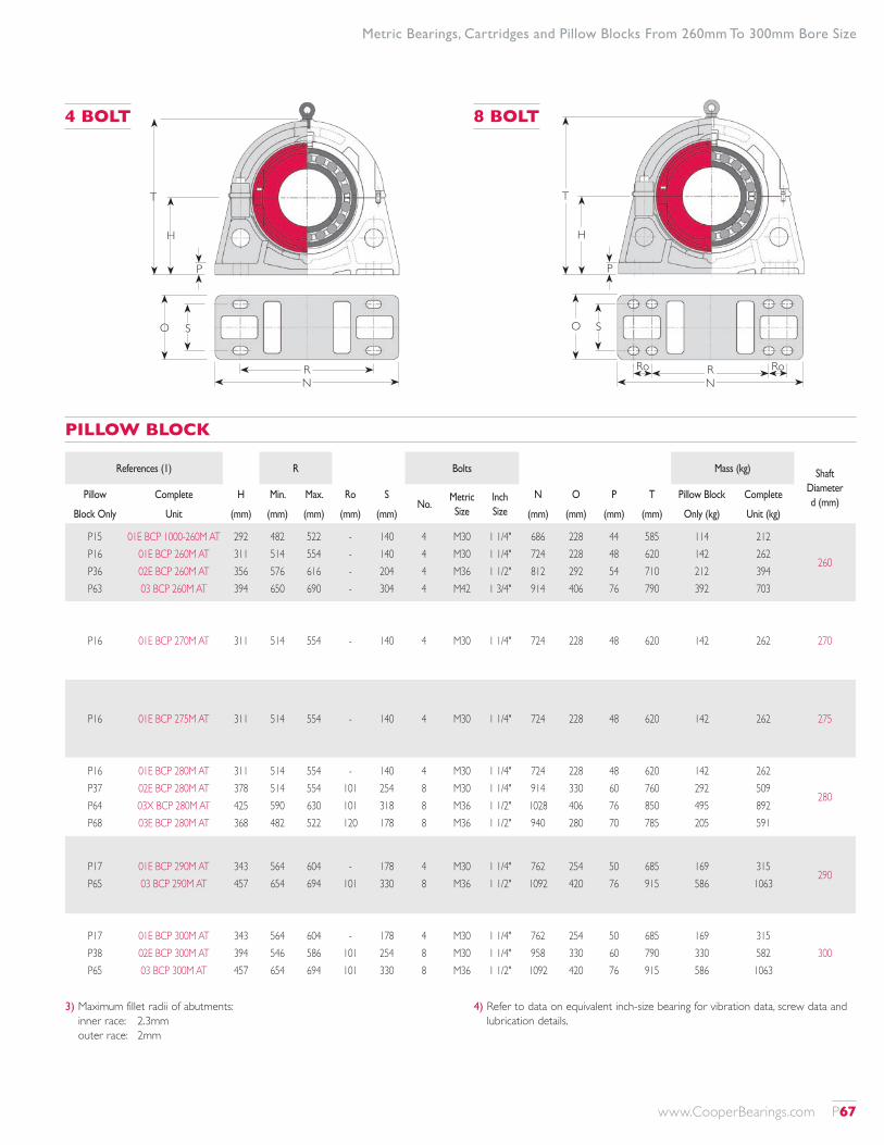
References (1) R Bolts Mass (kg) Shaft Diameter d (mm)
Pillow Complete H Min. Max. Ro SNo.
Metric Size
Inch Size
N O P T Pillow Block Complete
Block Only Unit (mm) (mm) (mm) (mm) (mm) (mm) (mm) (mm) (mm) Only (kg) Unit (kg)
P15 P16 P36 P63
01E BCP 1000-260M AT 01E BCP 260M AT 02E BCP 260M AT 03 BCP 260M AT
292 311 356 394
482 514 576 650
522 554 616 690
- - - -
140 140 204 304
4 4 4 4
M30 M30 M36 M42
1 1/4" 1 1/4" 1 1/2" 1 3/4"
686 724 812 914
228 228 292 406
44 48 54 76
585 620 710 790
114 142 212 392
212 262 394 703
260
P16 01E BCP 270M AT 311 514 554 - 140 4 M30 1 1/4" 724 228 48 620 142 262 270
P16 01E BCP 275M AT 311 514 554 - 140 4 M30 1 1/4" 724 228 48 620 142 262 275
P16 P37 P64 P68
01E BCP 280M AT 02E BCP 280M AT 03X BCP 280M AT 03E BCP 280M AT
311 378 425 368
514 514 590 482
554 554 630 522
- 101 101 120
140 254 318 178
4 8 8 8
M30 M30 M36 M36
1 1/4" 1 1/4" 1 1/2" 1 1/2"
724 914 1028 940
228 330 406 280
48 60 76 70
620 760 850 785
142 292 495 205
262 509 892 591
280
P17 P65
01E BCP 290M AT 03 BCP 290M AT
343 457
564 654
604 694
- 101
178 330
4 8
M30 M36
1 1/4" 1 1/2"
762 1092
254 420
50 76
685 915
169 586
315 1063
290
P17 P38 P65
01E BCP 300M AT 02E BCP 300M AT 03 BCP 300M AT
343 394 457
564 546 654
604 586 694
- 101 101
178 254 330
4 8 8
M30 M30 M36
1 1/4" 1 1/4" 1 1/2"
762 958 1092
254 330 420
50 60 76
685 790 915
169 330 586
315 582 1063
300
PILLOW BLOCK
3) Maximum fillet radii of abutments: inner race: 2.3mm outer race: 2mm
4) Refer to data on equivalent inch-size bearing for vibration data, screw data and lubrication details.
RN
O S
T
H
P
T
H
P
R RoN
O S
Ro
4 BOLT 8 BOLT
Metric Bearings, Cartridges and Pillow Blocks From 260mm To 300mm Bore Size
www.CooperBearings.com P67
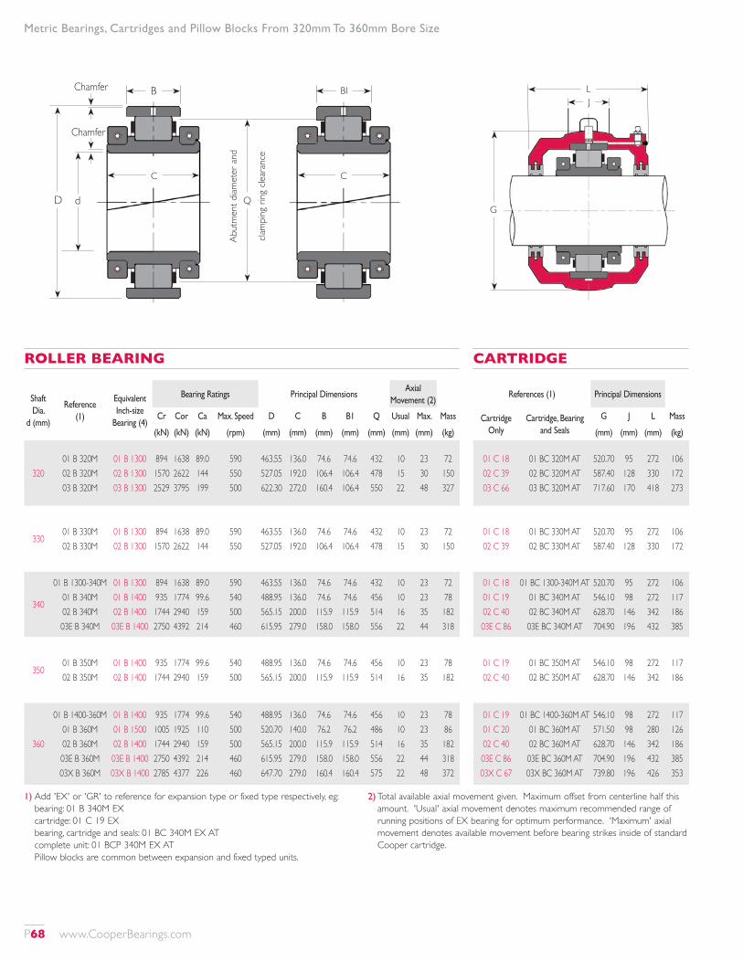
Shaft Dia.
d (mm)
Reference (1)
Equivalent Inch-size
Bearing (4)
Bearing Ratings Principal DimensionsAxial
Movement (2)
Cr Cor Ca Max. Speed D C B B1 Q Usual Max. Mass
(kN) (kN) (kN) (rpm) (mm) (mm) (mm) (mm) (mm) (mm) (mm) (kg)
32001 B 320M 02 B 320M 03 B 320M
01 B 1300 02 B 1300 03 B 1300
894 1570 2529
1638 2622 3795
89.0 144 199
590 550 500
463.55 527.05 622.30
136.0 192.0 272.0
74.6 106.4 160.4
74.6 106.4 106.4
432 478 550
10 15 22
23 30 48
72 150 327
33001 B 330M 02 B 330M
01 B 1300 02 B 1300
894 1570
1638 2622
89.0 144
590 550
463.55 527.05
136.0 192.0
74.6 106.4
74.6 106.4
432 478
10 15
23 30
72 150
340
01 B 1300-340M 01 B 340M 02 B 340M 03E B 340M
01 B 1300 01 B 1400 02 B 1400 03E B 1400
894 935 1744 2750
1638 1774 2940 4392
89.0 99.6 159 214
590 540 500 460
463.55 488.95 565.15 615.95
136.0 136.0 200.0 279.0
74.6 74.6 115.9 158.0
74.6 74.6 115.9 158.0
432 456 514 556
10 10 16 22
23 23 35 44
72 78 182 318
35001 B 350M 02 B 350M
01 B 1400 02 B 1400
935 1744
1774 2940
99.6 159
540 500
488.95 565.15
136.0 200.0
74.6 115.9
74.6 115.9
456 514
10 16
23 35
78 182
360
01 B 1400-360M 01 B 360M 02 B 360M 03E B 360M 03X B 360M
01 B 1400 01 B 1500 02 B 1400 03E B 1400 03X B 1400
935 1005 1744 2750 2785
1774 1925 2940 4392 4377
99.6 110 159 214 226
540 500 500 460 460
488.95 520.70 565.15 615.95 647.70
136.0 140.0 200.0 279.0 279.0
74.6 76.2 115.9 158.0 160.4
74.6 76.2 115.9 158.0 160.4
456 486 514 556 575
10 10 16 22 22
23 23 35 44 48
78 86 182 318 372
ROLLER BEARING
References (1) Principal Dimensions
Cartridge Only
Cartridge, Bearing and Seals
G J L Mass
(mm) (mm) (mm) (kg)
01 C 18 02 C 39 03 C 66
01 BC 320M AT 02 BC 320M AT 03 BC 320M AT
520.70 587.40 717.60
95 128 170
272 330 418
106 172 273
01 C 18 02 C 39
01 BC 330M AT 02 BC 330M AT
520.70 587.40
95 128
272 330
106 172
01 C 18 01 C 19 02 C 40 03E C 86
01 BC 1300-340M AT 01 BC 340M AT 02 BC 340M AT 03E BC 340M AT
520.70 546.10 628.70 704.90
95 98 146 196
272 272 342 432
106 117 186 385
01 C 19 02 C 40
01 BC 350M AT 02 BC 350M AT
546.10 628.70
98 146
272 342
117 186
01 C 19 01 C 20 02 C 40 03E C 86 03X C 67
01 BC 1400-360M AT 01 BC 360M AT 02 BC 360M AT 03E BC 360M AT 03X BC 360M AT
546.10 571.50 628.70 704.90 739.80
98 98 146 196 196
272 280 342 432 426
117 126 186 385 353
CARTRIDGE
1) Add 'EX' or 'GR' to reference for expansion type or fixed type respectively, eg: bearing: 01 B 340M EX cartridge: 01 C 19 EX bearing, cartridge and seals: 01 BC 340M EX AT complete unit: 01 BCP 340M EX AT Pillow blocks are common between expansion and fixed typed units.
2) Total available axial movement given. Maximum offset from centerline half this amount. 'Usual' axial movement denotes maximum recommended range of running positions of EX bearing for optimum performance. 'Maximum' axial movement denotes available movement before bearing strikes inside of standard Cooper cartridge.
Metric Bearings, Cartridges and Pillow Blocks From 320mm To 360mm Bore Size
G
LJ
B
D d
Chamfer
Chamfer
BI
C
Q
Abut
men
t diam
eter
and
clam
ping
ring
clea
ranc
e
C
P68 www.CooperBearings.com

References (1) R Bolts Mass (kg) Shaft Diameter d (mm)
Pillow Complete H Min. Max. Ro SNo.
Metric Size
Inch Size
N O P T Pillow Block Complete
Block Only Unit (mm) (mm) (mm) (mm) (mm) (mm) (mm) (mm) (mm) Only (kg) Unit (kg)
P18 P39 P66
01 BCP 320M AT 02 BCP 320M AT 03 BCP 320M AT
368 419 518
602 590 742
642 630 782
- 101 108
178 210 266
4 8 8
M36 M30 M36
1 1/2" 1 1/4" 1 1/2"
812 1016 1194
254 292 356
54 64 80
735 840 1035
196 383 655
374 705 1255
320
P18 P39
01 BCP 330M AT 02 BCP 330M AT
368 419
602 590
642 630
- 101
178 210
4 8
M36 M30
1 1/2" 1 1/4"
812 1016
254 292
54 64
735 840
196 383
374 705
330
P16 P19 P40 P86
01 BCP 1300-340M AT 01 BCP 340M AT 02 BCP 340M AT 03E BCP 340M AT
368 387 451 470
602 634 640 634
642 674 680 686
- -
102 134
178 166 280 190
4 4 8 8
M36 M36 M36 M42
1 1/2" 1 1/2" 1 1/2" 1 3/4"
812 850 1092 1220
254 254 368 318
54 57 67 82
735 775 900 1000
196 213 429 464
374 408 797 1167
340
P19 P40
01 BCP 350M AT 02 BCP 350M AT
387 451
634 640
674 680
- 102
166 280
4 8
M36 M36
1 1/2" 1 1/2"
850 1092
254 368
57 67
775 900
213 429
408 797
350
P19 P20 P40 P86 P67
01 BCP 1400-360M AT 01 BCP 360M AT 02 BCP 360M AT 03E BCP 360M AT 03X BCP 360M AT
387 397 451 470 533
634 656 640 634 758
674 696 680 686 810
- -
102 134 114
166 166 280 190 266
4 4 8 8 8
M36 M36 M36 M42 M42
1 1/2" 1 1/2" 1 1/2" 1 3/4" 1 3/4"
850 902 1092 1220 1244
254 254 368 318 368
57 60 67 82 90
775 795 900 1000 1065
213 288 429 464 820
408 500 797 1167 1545
360
PILLOW BLOCK
3) Maximum fillet radii of abutments: inner race: 2.3mm outer race: 2mm
4) Refer to data on equivalent inch-size bearing for vibration data, screw data and lubrication details.
RN
O S
T
H
P
T
H
P
R RoN
O S
Ro
4 BOLT 8 BOLT
Metric Bearings, Cartridges and Pillow Blocks From 320mm To 360mm Bore Size
www.CooperBearings.com P69
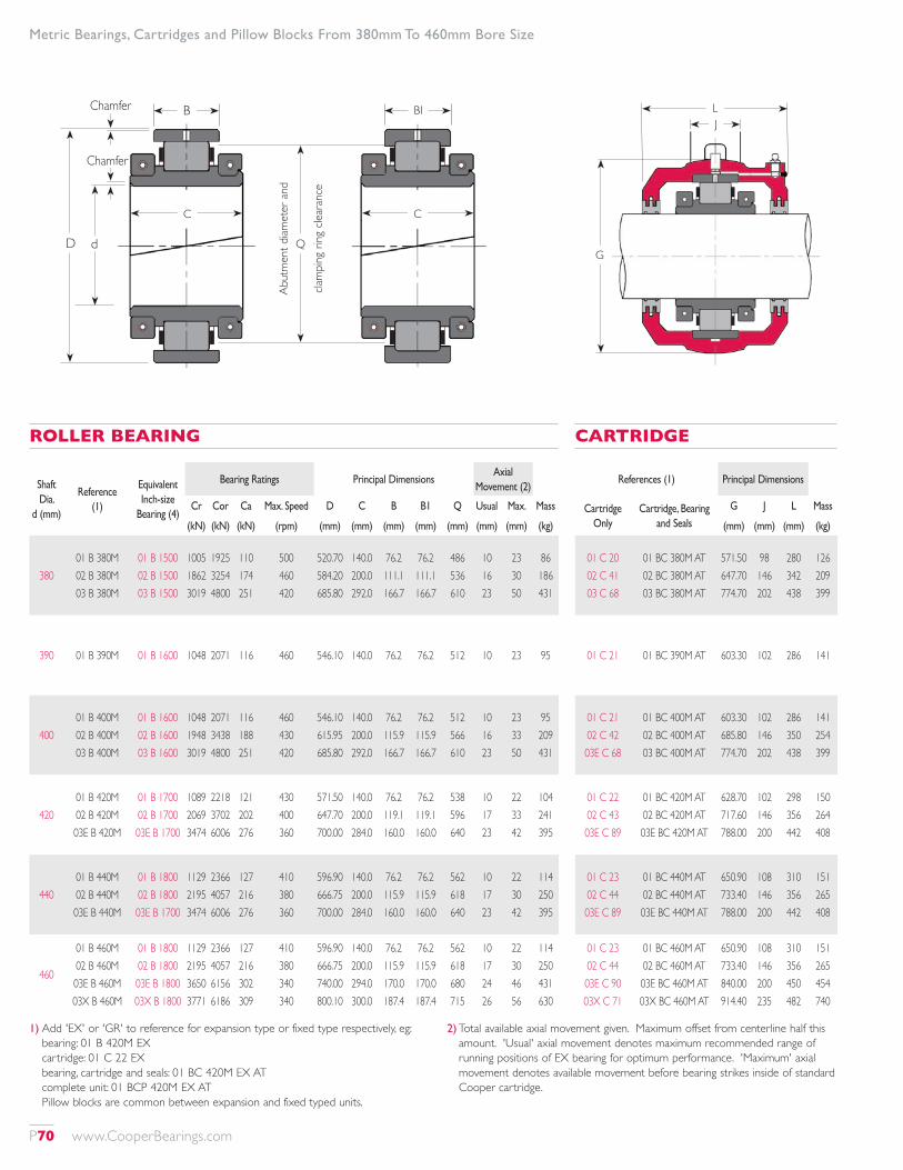
Shaft Dia.
d (mm)
Reference (1)
Equivalent Inch-size
Bearing (4)
Bearing Ratings Principal DimensionsAxial
Movement (2)
Cr Cor Ca Max. Speed D C B B1 Q Usual Max. Mass
(kN) (kN) (kN) (rpm) (mm) (mm) (mm) (mm) (mm) (mm) (mm) (kg)
38001 B 380M 02 B 380M 03 B 380M
01 B 1500 02 B 1500 03 B 1500
1005 1862 3019
1925 3254 4800
110 174 251
500 460 420
520.70 584.20 685.80
140.0 200.0 292.0
76.2 111.1 166.7
76.2 111.1 166.7
486 536 610
10 16 23
23 30 50
86 186 431
390 01 B 390M 01 B 1600 1048 2071 116 460 546.10 140.0 76.2 76.2 512 10 23 95
40001 B 400M 02 B 400M 03 B 400M
01 B 1600 02 B 1600 03 B 1600
1048 1948 3019
2071 3438 4800
116 188 251
460 430 420
546.10 615.95 685.80
140.0 200.0 292.0
76.2 115.9 166.7
76.2 115.9 166.7
512 566 610
10 16 23
23 33 50
95 209 431
42001 B 420M 02 B 420M 03E B 420M
01 B 1700 02 B 1700 03E B 1700
1089 2069 3474
2218 3702 6006
121 202 276
430 400 360
571.50 647.70 700.00
140.0 200.0 284.0
76.2 119.1 160.0
76.2 119.1 160.0
538 596 640
10 17 23
22 33 42
104 241 395
44001 B 440M 02 B 440M 03E B 440M
01 B 1800 02 B 1800 03E B 1700
1129 2195 3474
2366 4057 6006
127 216 276
410 380 360
596.90 666.75 700.00
140.0 200.0 284.0
76.2 115.9 160.0
76.2 115.9 160.0
562 618 640
10 17 23
22 30 42
114 250 395
460
01 B 460M 02 B 460M 03E B 460M 03X B 460M
01 B 1800 02 B 1800 03E B 1800 03X B 1800
1129 2195 3650 3771
2366 4057 6156 6186
127 216 302 309
410 380 340 340
596.90 666.75 740.00 800.10
140.0 200.0 294.0 300.0
76.2 115.9 170.0 187.4
76.2 115.9 170.0 187.4
562 618 680 715
10 17 24 26
22 30 46 56
114 250 431 630
ROLLER BEARING
References (1) Principal Dimensions
Cartridge Only
Cartridge, Bearing and Seals
G J L Mass
(mm) (mm) (mm) (kg)
01 C 20 02 C 41 03 C 68
01 BC 380M AT 02 BC 380M AT 03 BC 380M AT
571.50 647.70 774.70
98 146 202
280 342 438
126 209 399
01 C 21 01 BC 390M AT 603.30 102 286 141
01 C 21 02 C 42 03E C 68
01 BC 400M AT 02 BC 400M AT 03 BC 400M AT
603.30 685.80 774.70
102 146 202
286 350 438
141 254 399
01 C 22 02 C 43 03E C 89
01 BC 420M AT 02 BC 420M AT 03E BC 420M AT
628.70 717.60 788.00
102 146 200
298 356 442
150 264 408
01 C 23 02 C 44 03E C 89
01 BC 440M AT 02 BC 440M AT 03E BC 440M AT
650.90 733.40 788.00
108 146 200
310 356 442
151 265 408
01 C 23 02 C 44 03E C 90 03X C 71
01 BC 460M AT 02 BC 460M AT 03E BC 460M AT 03X BC 460M AT
650.90 733.40 840.00 914.40
108 146 200 235
310 356 450 482
151 265 454 740
CARTRIDGE
1) Add 'EX' or 'GR' to reference for expansion type or fixed type respectively, eg: bearing: 01 B 420M EX cartridge: 01 C 22 EX bearing, cartridge and seals: 01 BC 420M EX AT complete unit: 01 BCP 420M EX AT Pillow blocks are common between expansion and fixed typed units.
2) Total available axial movement given. Maximum offset from centerline half this amount. 'Usual' axial movement denotes maximum recommended range of running positions of EX bearing for optimum performance. 'Maximum' axial movement denotes available movement before bearing strikes inside of standard Cooper cartridge.
Metric Bearings, Cartridges and Pillow Blocks From 380mm To 460mm Bore Size
G
LJ
B
D d
Chamfer
Chamfer
BI
C
Q
Abut
men
t diam
eter
and
clam
ping
ring
clea
ranc
e
C
P70 www.CooperBearings.com
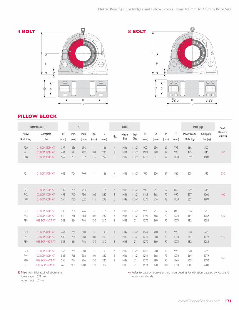
References (1) R Bolts Mass (kg) Shaft Diameter d (mm)
Pillow Complete H Min. Max. Ro SNo.
Metric Size
Inch Size
N O P T Pillow Block Complete
Block Only Unit (mm) (mm) (mm) (mm) (mm) (mm) (mm) (mm) (mm) Only (kg) Unit (kg)
P20 P41 P68
01 BCP 380M AT 02 BCP 380M AT 03 BCP 380M AT
397 466 559
656 662 780
696 702 832
- 102 115
166 280 292
4 8 8
M36 M36 M42
1 1/2" 1 1/2" 1 3/4"
902 1092 1270
254 368 394
60 67 92
795 925 1120
288 445 859
500 840 1689
380
P21 01 BCP 390M AT 432 704 744 - 166 4 M36 1 1/2" 940 254 67 865 309 545 390
P21 P42 P68
01 BCP 400M AT 02 BCP 400M AT 03 BCP 400M AT
432 495 559
704 710 780
744 750 832
- 102 115
166 280 292
4 8 8
M36 M36 M42
1 1/2" 1 1/2" 1 3/4"
940 1168 1270
254 368 394
67 70 92
865 990 1120
309 537 859
545 1000 1689
400
P22 P43 P89
01 BCP 420M AT 02 BCP 420M AT 03E BCP 420M AT
445 514 508
736 748 664
776 788 716
- 102 150
166 280 210
4 8 8
M36 M36 M48
1 1/2" 1 1/2"
2"
966 1194 1270
254 368 360
67 70 90
890 1030 1075
316 564 482
570 1069 1285
420
P23 P44 P89
01 BCP 440M AT 02 BCP 440M AT 03E BCP 440M AT
464 533 508
768 768 664
808 808 716
- 104 150
190 280 210
4 8 8
M42 M36 M48
1 3/4" 1 1/2"
2"
1042 1244 1270
280 368 360
70 73 90
925 1070 1075
370 564 482
635 1079 1285
440
P23 P44 P90 P71
01 BCP 460M AT 02 BCP 460M AT 03E BCP 460M AT 03X BCP 460M AT
464 533 550 660
768 768 754 908
808 808 806 960
- 104 150 178
190 280 220 362
4 8 8 8
M42 M36 M48 M48
1 3/4" 1 1/2"
2" 2"
1042 1244 1370 1574
280 368 380 470
70 73 95 108
925 1070 1165 1320
370 564 705 1330
635 1079 1590 2700
460
PILLOW BLOCK
3) Maximum fillet radii of abutments: inner race: 2.3mm outer race: 2mm
4) Refer to data on equivalent inch-size bearing for vibration data, screw data and lubrication details.
RN
O S
T
H
P
T
H
P
R RoN
O S
Ro
4 BOLT 8 BOLT
Metric Bearings, Cartridges and Pillow Blocks From 380mm To 460mm Bore Size
www.CooperBearings.com P71
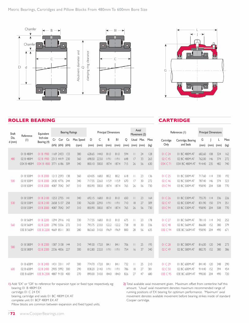
Shaft Dia.
d (mm)
Reference (1)
Equivalent Inch-size
Bearing (4)
Bearing Ratings Principal DimensionsAxial
Movement (2)
Cr Cor Ca Max. Speed D C B B1 Q Usual Max. Mass
(kN) (kN) (kN) (rpm) (mm) (mm) (mm) (mm) (mm) (mm) (mm) (kg)
48001 B 480M 02 B 480M
03X B 480M
01 B 1900 02 B 1900
03X B 1800
1169 2313 3771
2433 4419 6186
133 230 309
380 360 340
628.65 698.50 800.10
144.0 223.0 300.0
81.0 119.1 187.4
81.0 119.1 187.4
594 648 715
11 17 26
24 33 56
128 263 630
50001 B 500M 02 B 500M 03 B 500M
01 B 2000 02 B 2000 03 B 2000
1213 2430 4087
2593 4776 7042
138 244 347
360 340 310
654.05 717.55 850.90
168.0 226.0 300.0
80.2 115.9 187.4
80.2 115.9 187.4
618 670 765
11 17 26
23 30 56
136 272 730
53001 B 530M 02 B 530M 03 B 530M
01 B 2100 02 B 2100 03 B 2000
1253 2658 4087
2755 5137 7042
141 258 347
340 330 310
692.15 762.00 850.90
168.0 229.0 300.0
81.0 119.1 187.4
81.0 119.1 187.4
650 710 765
11 18 26
23 27 56
164 309 730
56001 B 560M 02 B 560M 03E B 560M
01 B 2200 02 B 2200 03E B 2200
1294 2790 4669
2916 5556 8511
142 272 383
330 310 280
717.55 793.75 863.60
168.0 233.0 310.0
81.0 122.2 196.9
81.0 122.2 196.9
675 738 800
11 18 28
23 30 56
178 336 635
58001 B 580M 02 B 580M
01 B 2300 02 B 2300
1387 2336
3138 4836
144 227
310 300
749.30 812.80
172.0 232.0
84.1 119.1
84.1 119.1
706 754
11 16
25 37
195 340
60001 B 600M 02 B 600M 03E B 600M
01 B 2400 02 B 2400 03E B 2300
1431 2905 4887
3311 5992 9130
147 300 400
300 290 270
774.70 838.20 890.00
172.0 214.0 310.0
84.1 119.1 184.0
84.1 119.1 184.0
732 786 826
11 18 27
25 27 47
210 381 680
ROLLER BEARING
References (1) Principal Dimensions
Cartridge Only
Cartridge, Bearing and Seals
G J L Mass
(mm) (mm) (mm) (kg)
01 C 24 02 C 45
03X C 71
01 BC 480M AT 02 BC 480M AT
03X BC 480M AT
682.60 762.00 914.40
108 146 235
324 374 482
162 272 740
01 C 25 02 C 46 03 C 94
01 BC 500M AT 02 BC 500M AT 03 BC 500M AT
717.60 787.40 958.90
114 146 204
330 374 508
192 323 770
01 C 26 02 C 47 03 C 94
01 BC 530M AT 02 BC 530M AT 03 BC 530M AT
755.70 831.90 958.90
114 150 204
336 374 508
226 351 770
01 C 27 02 C 48 03E C 94
01 BC 560M AT 02 BC 560M AT 03E BC 560M AT
781.10 866.80 958.90
114 152 204
342 380 490
252 379 671
01 C 28 02 C 49
01 BC 580M AT 02 BC 580M AT
816.00 882.70
120 152
348 380
273 386
01 C 29 02 C 50 03E C 95
01 BC 600M AT 02 BC 600M AT 03E BC 600M AT
841.40 914.40 990.00
120 152 204
348 394 490
290 454 720
CARTRIDGE
1) Add 'EX' or 'GR' to reference for expansion type or fixed type respectively, eg: bearing: 01 B 480M EX cartridge: 01 C 24 EX bearing, cartridge and seals: 01 BC 480M EX AT complete unit: 01 BCP 480M EX AT Pillow blocks are common between expansion and fixed typed units.
2) Total available axial movement given. Maximum offset from centerline half this amount. 'Usual' axial movement denotes maximum recommended range of running positions of EX bearing for optimum performance. 'Maximum' axial movement denotes available movement before bearing strikes inside of standard Cooper cartridge.
Metric Bearings, Cartridges and Pillow Blocks From 480mm To 600mm Bore Size
G
LJ
B
D d
Chamfer
Chamfer
BI
C
Q
Abut
men
t diam
eter
and
clam
ping
ring
clea
ranc
e
C
P72 www.CooperBearings.com

References (1) R Bolts Mass (kg) Shaft Diameter d (mm)
Pillow Complete H Min. Max. Ro SNo.
Metric Size
Inch Size
N O P T Pillow Block Complete
Block Only Unit (mm) (mm) (mm) (mm) (mm) (mm) (mm) (mm) (mm) Only (kg) Unit (kg)
P24 P45 P71
01 BCP 480M AT 02 BCP 480M AT
03X BCP 480M AT
483 552 660
796 792 908
836 832 960
- 115 178
188 280 362
4 8 8
M42 M36 M48
1 3/4" 1 1/2"
2"
1092 1270 1574
304 368 470
73 76 108
965 1110 1320
402 690 1330
692 1225 2700
480
P25 P46 P94
01 BCP 500M AT 02 BCP 500M AT 03 BCP 500M AT
489 572 622
824 824 914
864 864 966
- 115 165
216 280 242
4 8 8
M42 M36 M56
1 3/4" 1 1/2" 2 1/4"
1092 1296 1600
304 368 406
76 80 102
980 1145 1340
402 677 1000
730 1272 2500
500
P26 P47 P94
01 BCP 530M AT 02 BCP 530M AT 03 BCP 530M AT
533 591 622
884 870 914
924 910 966
- 114 165
206 280 242
4 8 8
M42 M36 M56
1 3/4" 1 1/2" 2 1/4"
1194 1398 1600
304 368 406
80 83 102
1065 1180 1340
495 905 1000
885 1565 2500
530
P27 P48 P94
01 BCP 560M AT 02 BCP 560M AT 03E BCP 560M AT
552 616 622
916 904 914
956 956 966
- 114 165
206 280 242
4 8 8
M42 M42 M56
1 3/4" 1 3/4" 2 1/4"
1220 1422 1600
304 382 406
83 86 102
1110 1230 1340
570 965 1000
1000 1680 2306
560
P28 P49
01 BCP 580M AT 02 BCP 580M AT
578 635
857 932
896 984
102 115
220 280
8 8
M36 M42
1 1/2" 1 3/4"
1346 1448
304 382
90 90
1156 1270
630 1000
1098 1726
580
P29 P50 P95
01 BCP 600M AT 02 BCP 600M AT 03E BCP 600M AT
597 673 622
888 984 914
928 1036 966
105 114 165
220 280 242
8 8 8
M36 M42 M56
1 1/2" 1 3/4" 2 1/4"
1372 1524 1600
304 382 406
90 92 102
1200 1345 1340
630 1050 930
1130 1885 2330
600
PILLOW BLOCK
3) Maximum fillet radii of abutments: inner race: 2.3mm outer race: 2mm
4) Refer to data on equivalent inch-size bearing for vibration data, screw data and lubrication details.
RN
O S
T
H
P
T
H
P
R RoN
O S
Ro
4 BOLT 8 BOLT
Metric Bearings, Cartridges and Pillow Blocks From 480mm To 600mm Bore Size
www.CooperBearings.com P73
Marine Specification Pillow Blocks
MARINE SPECIFICATION PILLOW BLOCKSAs well as the standard specification pillow blocks, Cooper manufacture a range of pillow blocks with additional features intended to aid their application to marine drive systems. These additional features comprise:
• ‘Solid’ base (without lightening cores to the underside) to provide a large surface area for use with chocking compound
• Jacking screw holes to aid initial height adjustment (usually before application of chocking compound)
• Lubrication of the spherical seat, to allow changing alignment of the shaft and pillow block in service
All of these features can be included on any size of pillow block either individually or in combination, but on the range of pillow blocks shown in the table on the next page they are all included as standard. For other sizes of pillow block, or if only certain features are required, please contact our technical department for relevant part codes.These ‘marine specification’ pillow blocks may be used in place of standard pillow blocks as shown in the table. It is possible to
mount any combination of bearing and cartridge which would usually be mounted in the standard pillow block in the equivalent marine specification pillow block.Pillow blocks of the Z Series (e.g. Z06) have the same bolt hole spacings, footprint dimensions and centerline heights as the equivalent standard pillow blocks. The dimensions of other pillow blocks in the table may differ from the standard pillow blocks, and the references for standard pillow blocks are only to indicate bearing and cartridge compatibility.Pillow blocks may also feature drillings for temperature elements. Provision for temperature elements (when specified) is usually made by a suitable hole in the cartridge only, with the probe inserted axially. However, when there is insufficient space for an axially oriented probe, a radial orientation is possible. The temperature probe is then mounted on the pillow block cap, with corresponding drillings through the pillow block and cartridge. Please consult our technical department for details.
P74 www.CooperBearings.com
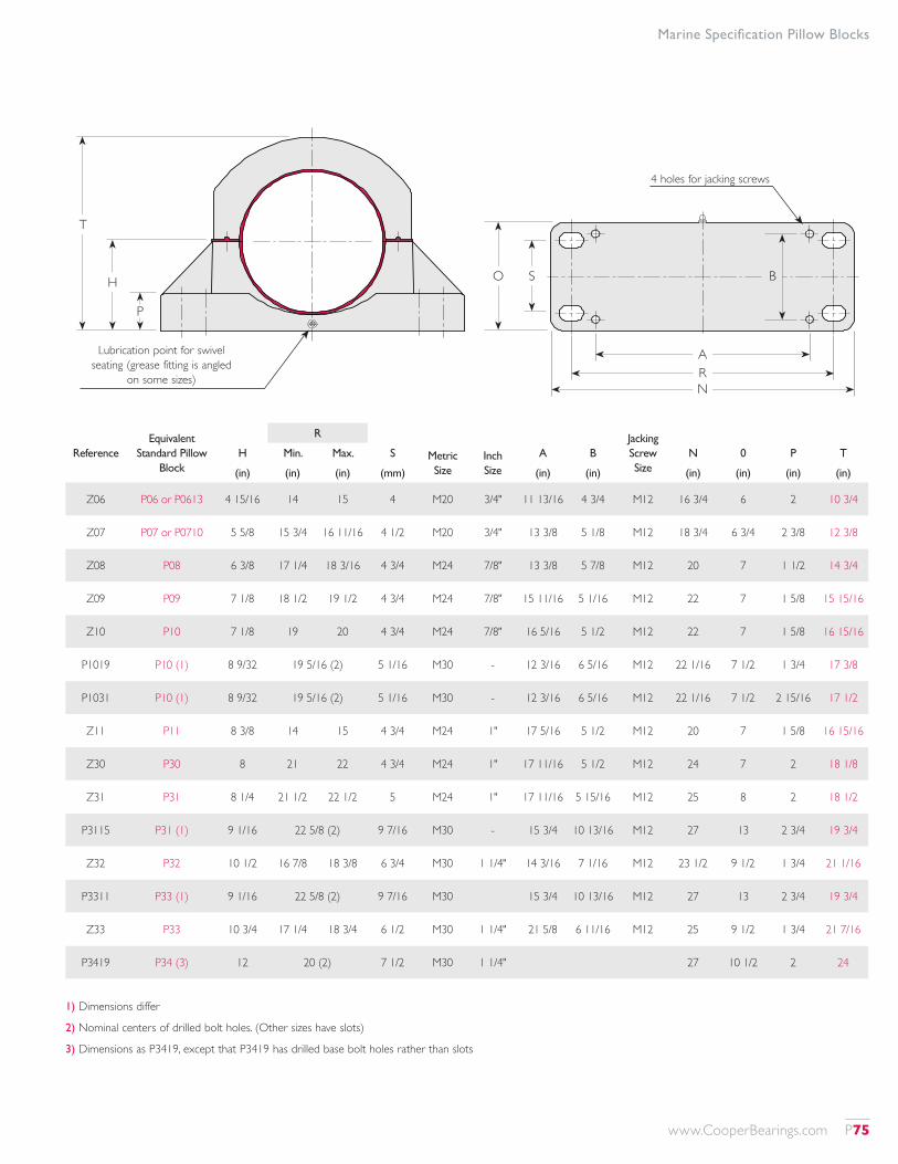
Marine Specification Pillow Blocks
1) Dimensions differ
2) Nominal centers of drilled bolt holes. (Other sizes have slots)
3) Dimensions as P3419, except that P3419 has drilled base bolt holes rather than slots
T
H
P
Lubrication point for swivel seating (grease fitting is angled
on some sizes)
4 holes for jacking screws
O
ARN
S B
ReferenceEquivalent
Standard Pillow Block
R Jacking Screw Size
H Min. Max. S Metric Size
Inch Size
A B N 0 P T
(in) (in) (in) (mm) (in) (in) (in) (in) (in) (in)
Z06 P06 or P0613 4 15/16 14 15 4 M20 3/4" 11 13/16 4 3/4 M12 16 3/4 6 2 10 3/4
Z07 P07 or P0710 5 5/8 15 3/4 16 11/16 4 1/2 M20 3/4" 13 3/8 5 1/8 M12 18 3/4 6 3/4 2 3/8 12 3/8
Z08 P08 6 3/8 17 1/4 18 3/16 4 3/4 M24 7/8" 13 3/8 5 7/8 M12 20 7 1 1/2 14 3/4
Z09 P09 7 1/8 18 1/2 19 1/2 4 3/4 M24 7/8" 15 11/16 5 1/16 M12 22 7 1 5/8 15 15/16
Z10 P10 7 1/8 19 20 4 3/4 M24 7/8" 16 5/16 5 1/2 M12 22 7 1 5/8 16 15/16
P1019 P10 (1) 8 9/32 19 5/16 (2) 5 1/16 M30 - 12 3/16 6 5/16 M12 22 1/16 7 1/2 1 3/4 17 3/8
P1031 P10 (1) 8 9/32 19 5/16 (2) 5 1/16 M30 - 12 3/16 6 5/16 M12 22 1/16 7 1/2 2 15/16 17 1/2
Z11 P11 8 3/8 14 15 4 3/4 M24 1" 17 5/16 5 1/2 M12 20 7 1 5/8 16 15/16
Z30 P30 8 21 22 4 3/4 M24 1" 17 11/16 5 1/2 M12 24 7 2 18 1/8
Z31 P31 8 1/4 21 1/2 22 1/2 5 M24 1" 17 11/16 5 15/16 M12 25 8 2 18 1/2
P3115 P31 (1) 9 1/16 22 5/8 (2) 9 7/16 M30 - 15 3/4 10 13/16 M12 27 13 2 3/4 19 3/4
Z32 P32 10 1/2 16 7/8 18 3/8 6 3/4 M30 1 1/4" 14 3/16 7 1/16 M12 23 1/2 9 1/2 1 3/4 21 1/16
P3311 P33 (1) 9 1/16 22 5/8 (2) 9 7/16 M30 15 3/4 10 13/16 M12 27 13 2 3/4 19 3/4
Z33 P33 10 3/4 17 1/4 18 3/4 6 1/2 M30 1 1/4" 21 5/8 6 11/16 M12 25 9 1/2 1 3/4 21 7/16
P3419 P34 (3) 12 20 (2) 7 1/2 M30 1 1/4" 27 10 1/2 2 24
www.CooperBearings.com P75
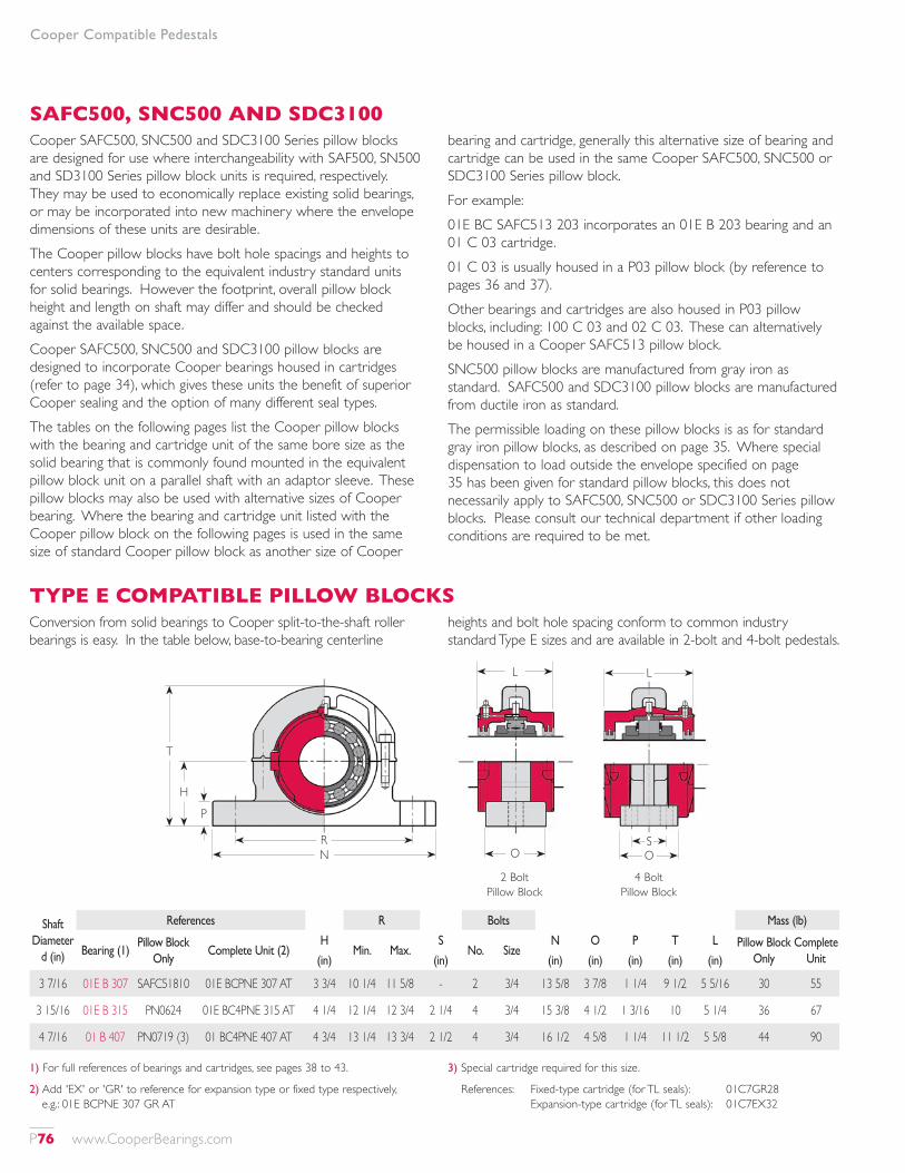
Cooper Compatible Pedestals
SAFC500, SNC500 AND SDC3100Cooper SAFC500, SNC500 and SDC3100 Series pillow blocks are designed for use where interchangeability with SAF500, SN500 and SD3100 Series pillow block units is required, respectively. They may be used to economically replace existing solid bearings, or may be incorporated into new machinery where the envelope dimensions of these units are desirable.The Cooper pillow blocks have bolt hole spacings and heights to centers corresponding to the equivalent industry standard units for solid bearings. However the footprint, overall pillow block height and length on shaft may differ and should be checked against the available space.Cooper SAFC500, SNC500 and SDC3100 pillow blocks are designed to incorporate Cooper bearings housed in cartridges (refer to page 34), which gives these units the benefit of superior Cooper sealing and the option of many different seal types.The tables on the following pages list the Cooper pillow blocks with the bearing and cartridge unit of the same bore size as the solid bearing that is commonly found mounted in the equivalent pillow block unit on a parallel shaft with an adaptor sleeve. These pillow blocks may also be used with alternative sizes of Cooper bearing. Where the bearing and cartridge unit listed with the Cooper pillow block on the following pages is used in the same size of standard Cooper pillow block as another size of Cooper
bearing and cartridge, generally this alternative size of bearing and cartridge can be used in the same Cooper SAFC500, SNC500 or SDC3100 Series pillow block.For example:01E BC SAFC513 203 incorporates an 01E B 203 bearing and an 01 C 03 cartridge.01 C 03 is usually housed in a P03 pillow block (by reference to pages 36 and 37).Other bearings and cartridges are also housed in P03 pillow blocks, including: 100 C 03 and 02 C 03. These can alternatively be housed in a Cooper SAFC513 pillow block.SNC500 pillow blocks are manufactured from gray iron as standard. SAFC500 and SDC3100 pillow blocks are manufactured from ductile iron as standard.The permissible loading on these pillow blocks is as for standard gray iron pillow blocks, as described on page 35. Where special dispensation to load outside the envelope specified on page 35 has been given for standard pillow blocks, this does not necessarily apply to SAFC500, SNC500 or SDC3100 Series pillow blocks. Please consult our technical department if other loading conditions are required to be met.
OS
L
O
L
T
HP
RN
1) For full references of bearings and cartridges, see pages 38 to 43.
2) Add 'EX' or 'GR' to reference for expansion type or fixed type respectively, e.g.: 01E BCPNE 307 GR AT
3) Special cartridge required for this size.
References: Fixed-type cartridge (for TL seals): 01C7GR28 Expansion-type cartridge (for TL seals): 01C7EX32
Shaft Diameter
d (in)
References R Bolts Mass (lb)
Bearing (1)Pillow Block
OnlyComplete Unit (2)
HMin. Max.
SNo. Size
N O P T L Pillow Block Only
Complete Unit(in) (in) (in) (in) (in) (in) (in)
3 7/16 01E B 307 SAFC51810 01E BCPNE 307 AT 3 3/4 10 1/4 11 5/8 - 2 3/4 13 5/8 3 7/8 1 1/4 9 1/2 5 5/16 30 55
3 15/16 01E B 315 PN0624 01E BC4PNE 315 AT 4 1/4 12 1/4 12 3/4 2 1/4 4 3/4 15 3/8 4 1/2 1 3/16 10 5 1/4 36 67
4 7/16 01 B 407 PN0719 (3) 01 BC4PNE 407 AT 4 3/4 13 1/4 13 3/4 2 1/2 4 3/4 16 1/2 4 5/8 1 1/4 11 1/2 5 5/8 44 90
TYPE E COMPATIBLE PILLOW BLOCKSConversion from solid bearings to Cooper split-to-the-shaft roller bearings is easy. In the table below, base-to-bearing centerline
heights and bolt hole spacing conform to common industry standard Type E sizes and are available in 2-bolt and 4-bolt pedestals.
2 Bolt Pillow Block
4 Bolt Pillow Block
P76 www.CooperBearings.com
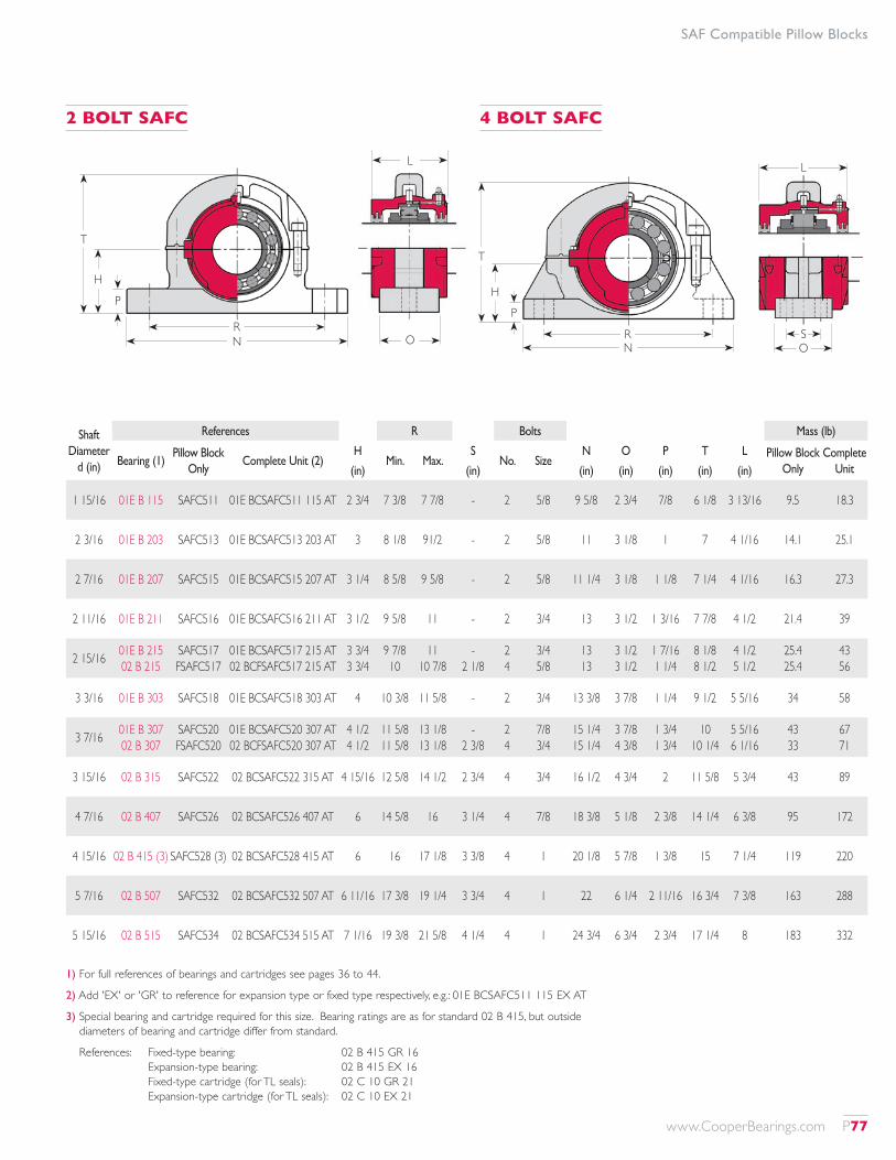
SAF Compatible Pillow Blocks
OS
L
T
HP
RNO
L
T
HP
RN
1) For full references of bearings and cartridges see pages 36 to 44.
2) Add 'EX' or 'GR' to reference for expansion type or fixed type respectively, e.g.: 01E BCSAFC511 115 EX AT
3) Special bearing and cartridge required for this size. Bearing ratings are as for standard 02 B 415, but outside diameters of bearing and cartridge differ from standard.
References: Fixed-type bearing: 02 B 415 GR 16 Expansion-type bearing: 02 B 415 EX 16 Fixed-type cartridge (for TL seals): 02 C 10 GR 21 Expansion-type cartridge (for TL seals): 02 C 10 EX 21
Shaft Diameter
d (in)
References R Bolts Mass (lb)
Bearing (1)Pillow Block
OnlyComplete Unit (2)
HMin. Max.
SNo. Size
N O P T L Pillow Block Only
Complete Unit(in) (in) (in) (in) (in) (in) (in)
1 15/16 01E B 115 SAFC511 01E BCSAFC511 115 AT 2 3/4 7 3/8 7 7/8 - 2 5/8 9 5/8 2 3/4 7/8 6 1/8 3 13/16 9.5 18.3
2 3/16 01E B 203 SAFC513 01E BCSAFC513 203 AT 3 8 1/8 91/2 - 2 5/8 11 3 1/8 1 7 4 1/16 14.1 25.1
2 7/16 01E B 207 SAFC515 01E BCSAFC515 207 AT 3 1/4 8 5/8 9 5/8 - 2 5/8 11 1/4 3 1/8 1 1/8 7 1/4 4 1/16 16.3 27.3
2 11/16 01E B 211 SAFC516 01E BCSAFC516 211 AT 3 1/2 9 5/8 11 - 2 3/4 13 3 1/2 1 3/16 7 7/8 4 1/2 21.4 39
2 15/16 01E B 215 02 B 215
SAFC517 FSAFC517
01E BCSAFC517 215 AT 02 BCFSAFC517 215 AT
3 3/4 3 3/4
9 7/8 10
11 10 7/8
- 2 1/8
2 4
3/4 5/8
13 13
3 1/2 3 1/2
1 7/16 1 1/4
8 1/8 8 1/2
4 1/2 5 1/2
25.4 25.4
43 56
3 3/16 01E B 303 SAFC518 01E BCSAFC518 303 AT 4 10 3/8 11 5/8 - 2 3/4 13 3/8 3 7/8 1 1/4 9 1/2 5 5/16 34 58
3 7/16 01E B 307 02 B 307
SAFC520 FSAFC520
01E BCSAFC520 307 AT 02 BCFSAFC520 307 AT
4 1/2 4 1/2
11 5/8 11 5/8
13 1/8 13 1/8
- 2 3/8
2 4
7/8 3/4
15 1/4 15 1/4
3 7/8 4 3/8
1 3/4 1 3/4
10 10 1/4
5 5/16 6 1/16
43 33
67 71
3 15/16 02 B 315 SAFC522 02 BCSAFC522 315 AT 4 15/16 12 5/8 14 1/2 2 3/4 4 3/4 16 1/2 4 3/4 2 11 5/8 5 3/4 43 89
4 7/16 02 B 407 SAFC526 02 BCSAFC526 407 AT 6 14 5/8 16 3 1/4 4 7/8 18 3/8 5 1/8 2 3/8 14 1/4 6 3/8 95 172
4 15/16 02 B 415 (3) SAFC528 (3) 02 BCSAFC528 415 AT 6 16 17 1/8 3 3/8 4 1 20 1/8 5 7/8 1 3/8 15 7 1/4 119 220
5 7/16 02 B 507 SAFC532 02 BCSAFC532 507 AT 6 11/16 17 3/8 19 1/4 3 3/4 4 1 22 6 1/4 2 11/16 16 3/4 7 3/8 163 288
5 15/16 02 B 515 SAFC534 02 BCSAFC534 515 AT 7 1/16 19 3/8 21 5/8 4 1/4 4 1 24 3/4 6 3/4 2 3/4 17 1/4 8 183 332
2 BOLT SAFC 4 BOLT SAFC
www.CooperBearings.com P77
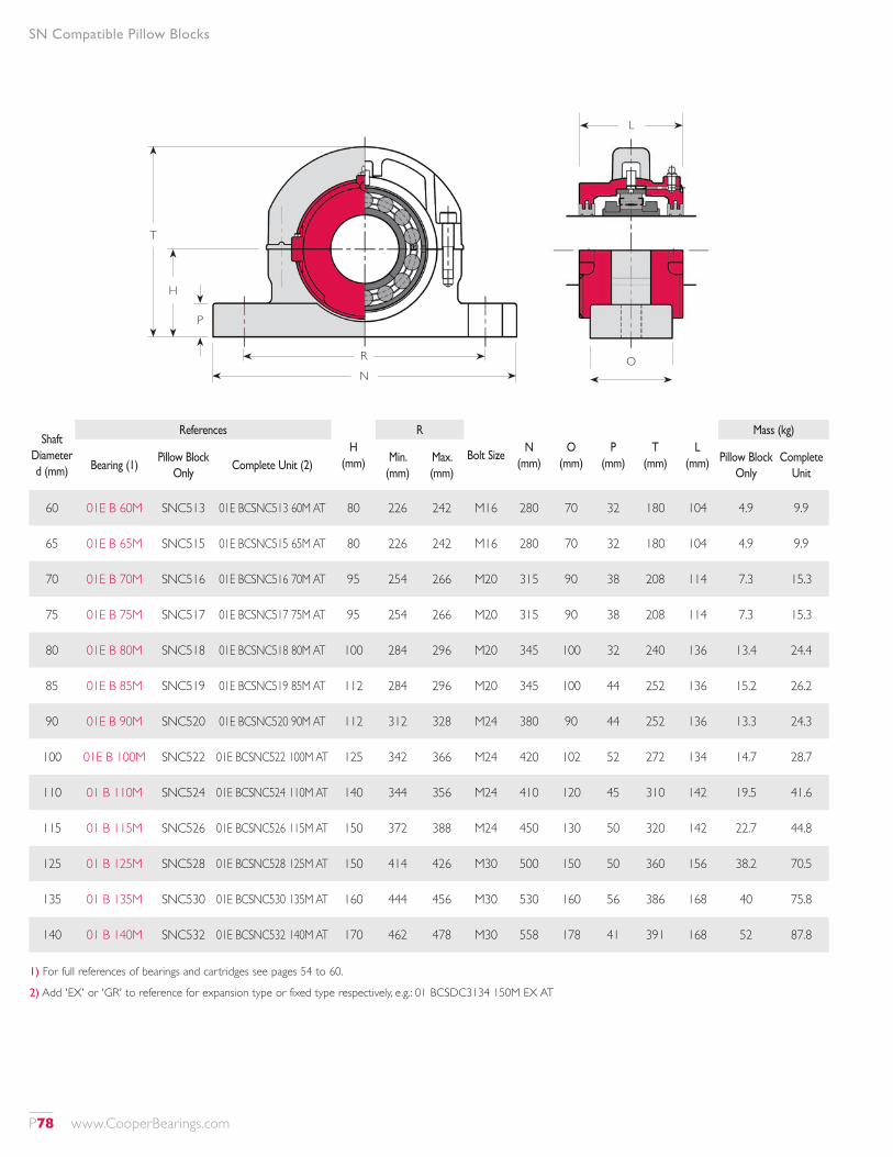
SN Compatible Pillow Blocks
Shaft Diameter d (mm)
ReferencesH
(mm)
R
Bolt Size N
(mm)O
(mm)P
(mm)T
(mm)L
(mm)
Mass (kg)
Bearing (1)Pillow Block
OnlyComplete Unit (2)
Min. (mm)
Max. (mm)
Pillow Block Only
Complete Unit
60 01E B 60M SNC513 01E BCSNC513 60M AT 80 226 242 M16 280 70 32 180 104 4.9 9.9
65 01E B 65M SNC515 01E BCSNC515 65M AT 80 226 242 M16 280 70 32 180 104 4.9 9.9
70 01E B 70M SNC516 01E BCSNC516 70M AT 95 254 266 M20 315 90 38 208 114 7.3 15.3
75 01E B 75M SNC517 01E BCSNC517 75M AT 95 254 266 M20 315 90 38 208 114 7.3 15.3
80 01E B 80M SNC518 01E BCSNC518 80M AT 100 284 296 M20 345 100 32 240 136 13.4 24.4
85 01E B 85M SNC519 01E BCSNC519 85M AT 112 284 296 M20 345 100 44 252 136 15.2 26.2
90 01E B 90M SNC520 01E BCSNC520 90M AT 112 312 328 M24 380 90 44 252 136 13.3 24.3
100 01E B 100M SNC522 01E BCSNC522 100M AT 125 342 366 M24 420 102 52 272 134 14.7 28.7
110 01 B 110M SNC524 01E BCSNC524 110M AT 140 344 356 M24 410 120 45 310 142 19.5 41.6
115 01 B 115M SNC526 01E BCSNC526 115M AT 150 372 388 M24 450 130 50 320 142 22.7 44.8
125 01 B 125M SNC528 01E BCSNC528 125M AT 150 414 426 M30 500 150 50 360 156 38.2 70.5
135 01 B 135M SNC530 01E BCSNC530 135M AT 160 444 456 M30 530 160 56 386 168 40 75.8
140 01 B 140M SNC532 01E BCSNC532 140M AT 170 462 478 M30 558 178 41 391 168 52 87.8
1) For full references of bearings and cartridges see pages 54 to 60.
2) Add 'EX' or 'GR' to reference for expansion type or fixed type respectively, e.g.: 01 BCSDC3134 150M EX AT
T
H
P
R
NO
L
P78 www.CooperBearings.com
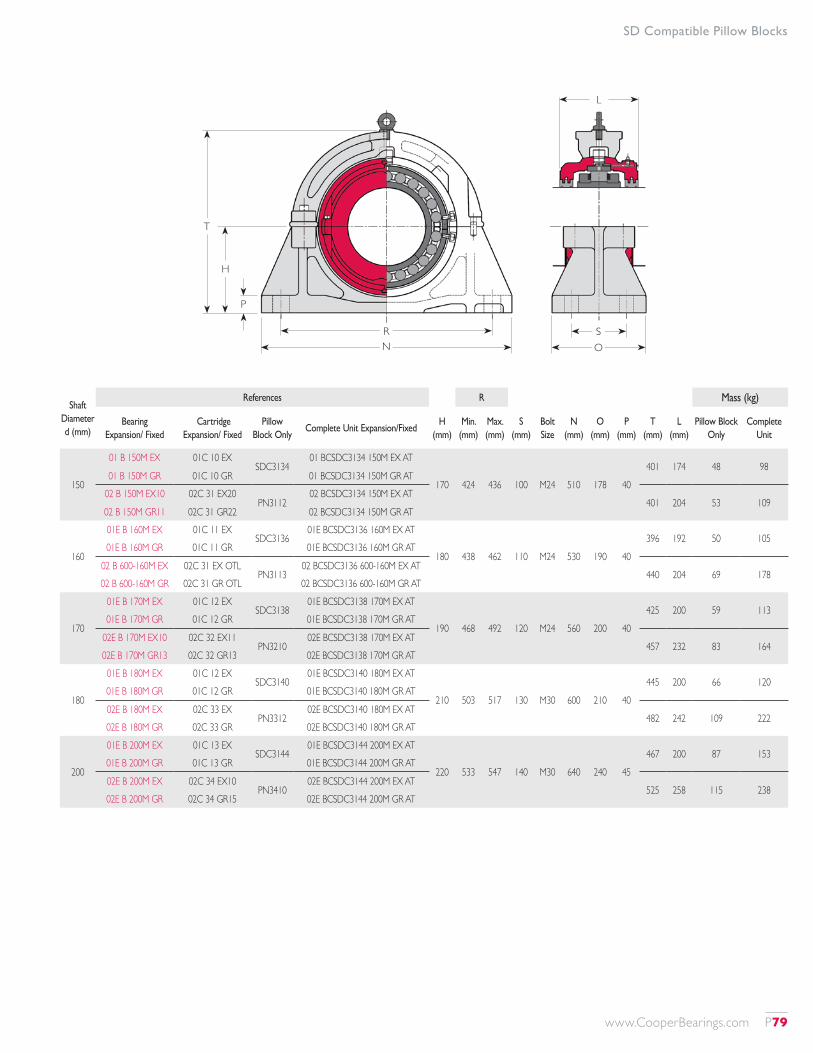
SD Compatible Pillow Blocks
Shaft Diameter d (mm)
References R Mass (kg)
Bearing Expansion/ Fixed
Cartridge Expansion/ Fixed
Pillow Block Only
Complete Unit Expansion/FixedH
(mm)Min.
(mm)Max. (mm)
S (mm)
Bolt Size
N (mm)
O (mm)
P (mm)
T (mm)
L (mm)
Pillow Block Only
Complete Unit
150
01 B 150M EX 01C 10 EXSDC3134
01 BCSDC3134 150M EX AT
170 424 436 100 M24 510 178 40401 174 48 98
01 B 150M GR 01C 10 GR 01 BCSDC3134 150M GR AT02 B 150M EX10 02C 31 EX20
PN311202 BCSDC3134 150M EX AT
401 204 53 10902 B 150M GR11 02C 31 GR22 02 BCSDC3134 150M GR AT
160
01E B 160M EX 01C 11 EXSDC3136
01E BCSDC3136 160M EX AT
180 438 462 110 M24 530 190 40396 192 50 105
01E B 160M GR 01C 11 GR 01E BCSDC3136 160M GR AT
02 B 600-160M EX 02C 31 EX OTLPN3113
02 BCSDC3136 600-160M EX AT440 204 69 178
02 B 600-160M GR 02C 31 GR OTL 02 BCSDC3136 600-160M GR AT
170
01E B 170M EX 01C 12 EXSDC3138
01E BCSDC3138 170M EX AT
190 468 492 120 M24 560 200 40425 200 59 113
01E B 170M GR 01C 12 GR 01E BCSDC3138 170M GR AT
02E B 170M EX10 02C 32 EX11PN3210
02E BCSDC3138 170M EX AT457 232 83 164
02E B 170M GR13 02C 32 GR13 02E BCSDC3138 170M GR AT
180
01E B 180M EX 01C 12 EXSDC3140
01E BCSDC3140 180M EX AT
210 503 517 130 M30 600 210 40445 200 66 120
01E B 180M GR 01C 12 GR 01E BCSDC3140 180M GR AT
02E B 180M EX 02C 33 EXPN3312
02E BCSDC3140 180M EX AT482 242 109 222
02E B 180M GR 02C 33 GR 02E BCSDC3140 180M GR AT
200
01E B 200M EX 01C 13 EXSDC3144
01E BCSDC3144 200M EX AT
220 533 547 140 M30 640 240 45467 200 87 153
01E B 200M GR 01C 13 GR 01E BCSDC3144 200M GR AT
02E B 200M EX 02C 34 EX10PN3410
02E BCSDC3144 200M EX AT525 258 115 238
02E B 200M GR 02C 34 GR15 02E BCSDC3144 200M GR AT
T
H
OS
P
RN
L
www.CooperBearings.com P79
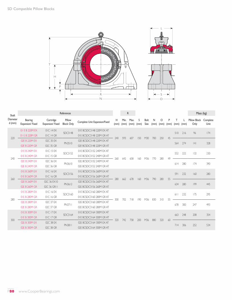
Shaft Diameter d (mm)
References R Mass (kg)
Bearing Expansion/ Fixed
Cartridge Expansion/ Fixed
Pillow Block Only
Complete Unit Expansion/FixedH
(mm)Min.
(mm)Max. (mm)
S (mm)
Bolt Size
N (mm)
O (mm)
P (mm)
T (mm)
L (mm)
Pillow Block Only
Complete Unit
220
01 E B 220M EX 01C 14 EXSDC3148
01E BCSDC3148 220M EX AT
240 593 607 150 M30 700 250 45510 216 96 174
01 E B 220M GR 01C 14 GR 01E BCSDC3148 220M GR AT
02E B 220M EX 02C 35 EXPN3510
02E BCSDC3148 220M EX AT564 274 141 328
02E B 220M GR 02C 35 GR 02E BCSDC3148 220M GR AT
240
01E B 240M EX 01C 15 EXSDC3152
01E BCSDC3152 240M EX AT
260 642 658 160 M36 770 280 49552 222 132 230
01E B 240M GR 01C 15 GR 01E BCSDC3152 240M GR AT
02E B 240M EX 02C 36 EXPN3610
02E BCSDC3152 240M EX AT614 280 174 390
02E B 240M GR 02C 36 GR 02E BCSDC3152 240M GR AT
260
01E B 260M EX 01C 16 EXSDC3156
01E BCSDC3156 260M EX AT
280 662 678 160 M36 790 280 55591 232 160 280
01E B 260M GR 01C 16 GR 01E BCSDC3156 260M GR AT
02E B 260M EX 02C 36 EX10PN3612
02E BCSDC3156 260M EX AT634 280 199 445
02E B 260M GR 02C 36 GR11 02E BCSDC3156 260M GR AT
280
01E B 280M EX 01C 16 EXSDC3160
01E BCSDC3160 280M EX AT
300 702 718 190 M36 830 310 55611 232 175 295
01E B 280M GR 01C 16 GR 01E BCSDC3160 280M GR AT
02E B 280M EX 02C 37 EXPN3711
02E BCSDC3160 280M EX AT678 300 247 493
02E B 280M GR 02C 37 GR 02E BCSDC3160 280M GR AT
300
01E B 300M EX 01C 17 EXSDC3164
01E BCSDC3164 300M EX AT
320 742 758 200 M36 880 320 60663 248 208 354
01E B 300M GR 01C 17 GR 01E BCSDC3164 300M GR AT
02E B 300M EX 02C 38 EXPN3811
02E BCSDC3164 300M EX AT714 306 252 534
02E B 300M GR 02C 38 GR 02E BCSDC3164 300M GR AT
T
H
OS
P
RN
L
SD Compatible Pillow Blocks
P80 www.CooperBearings.com
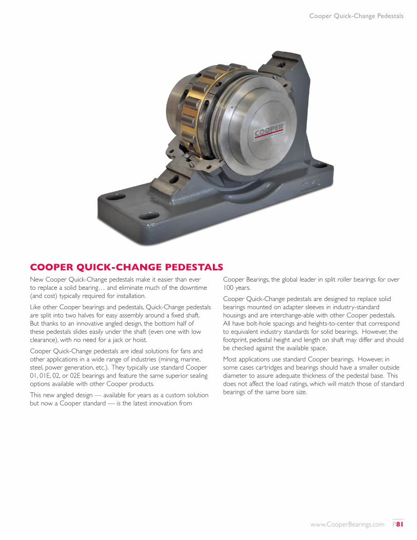
COOPER QUICK-CHANGE PEDESTALSNew Cooper Quick-Change pedestals make it easier than ever to replace a solid bearing… and eliminate much of the downtime (and cost) typically required for installation.Like other Cooper bearings and pedestals, Quick-Change pedestals are split into two halves for easy assembly around a fixed shaft. But thanks to an innovative angled design, the bottom half of these pedestals slides easily under the shaft (even one with low clearance), with no need for a jack or hoist.Cooper Quick-Change pedestals are ideal solutions for fans and other applications in a wide range of industries (mining, marine, steel, power generation, etc.). They typically use standard Cooper 01, 01E, 02, or 02E bearings and feature the same superior sealing options available with other Cooper products.This new angled design — available for years as a custom solution but now a Cooper standard — is the latest innovation from
Cooper Bearings, the global leader in split roller bearings for over 100 years.Cooper Quick-Change pedestals are designed to replace solid bearings mounted on adapter sleeves in industry-standard housings and are interchange-able with other Cooper pedestals. All have bolt-hole spacings and heights-to-center that correspond to equivalent industry standards for solid bearings. However, the footprint, pedestal height and length on shaft may differ and should be checked against the available space.Most applications use standard Cooper bearings. However, in some cases cartridges and bearings should have a smaller outside diameter to assure adequate thickness of the pedestal base. This does not affect the load ratings, which will match those of standard bearings of the same bore size.
Cooper Quick-Change Pedestals
www.CooperBearings.com P81
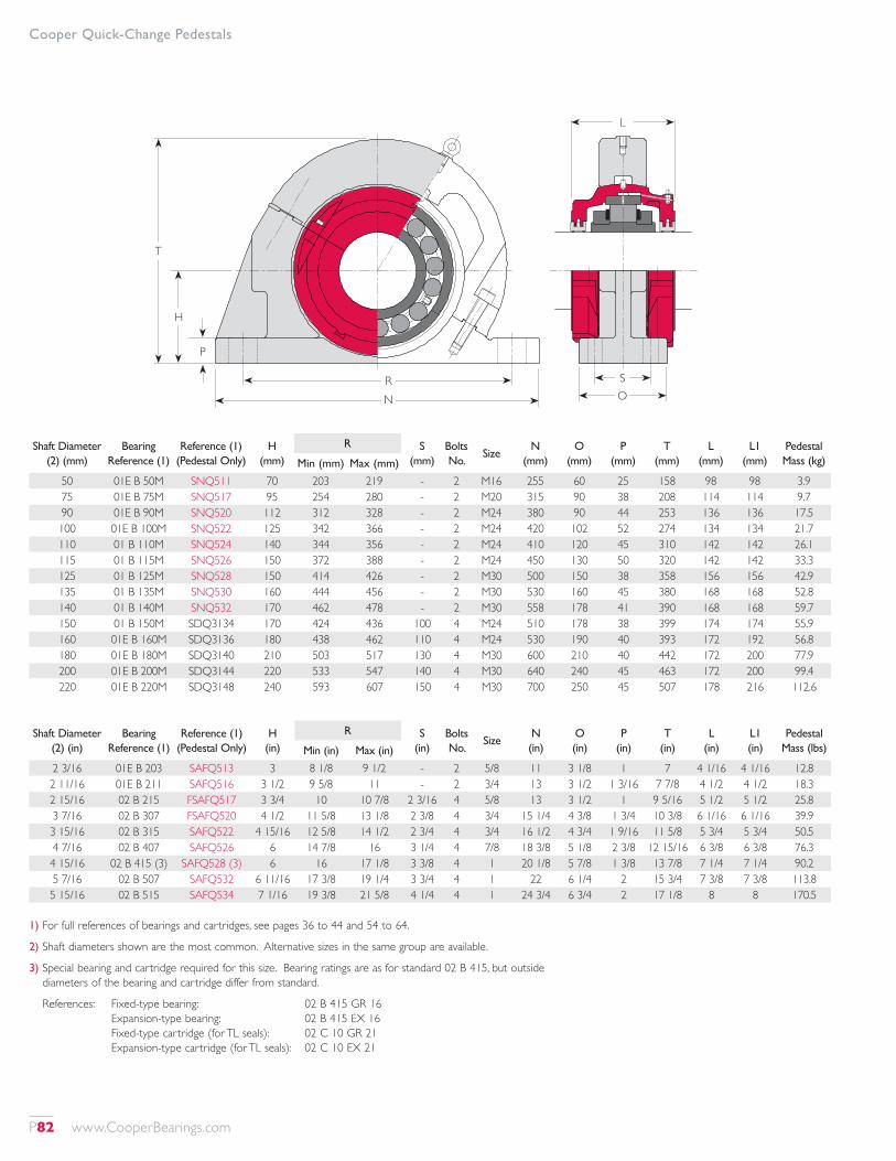
Cooper Quick-Change Pedestals
T
H
OS
P
RN
L
Shaft Diameter (2) (mm)
Bearing Reference (1)
Reference (1) (Pedestal Only)
H (mm)
R S (mm)
Bolts No.
SizeN
(mm)O
(mm)P
(mm)T
(mm)L
(mm)L1
(mm)Pedestal Mass (kg)Min (mm) Max (mm)
50 01E B 50M SNQ511 70 203 219 - 2 M16 255 60 25 158 98 98 3.975 01E B 75M SNQ517 95 254 280 - 2 M20 315 90 38 208 114 114 9.790 01E B 90M SNQ520 112 312 328 - 2 M24 380 90 44 253 136 136 17.5100 01E B 100M SNQ522 125 342 366 - 2 M24 420 102 52 274 134 134 21.7110 01 B 110M SNQ524 140 344 356 - 2 M24 410 120 45 310 142 142 26.1115 01 B 115M SNQ526 150 372 388 - 2 M24 450 130 50 320 142 142 33.3125 01 B 125M SNQ528 150 414 426 - 2 M30 500 150 38 358 156 156 42.9135 01 B 135M SNQ530 160 444 456 - 2 M30 530 160 45 380 168 168 52.8140 01 B 140M SNQ532 170 462 478 - 2 M30 558 178 41 390 168 168 59.7150 01 B 150M SDQ3134 170 424 436 100 4 M24 510 178 38 399 174 174 55.9160 01E B 160M SDQ3136 180 438 462 110 4 M24 530 190 40 393 172 192 56.8180 01E B 180M SDQ3140 210 503 517 130 4 M30 600 210 40 442 172 200 77.9200 01E B 200M SDQ3144 220 533 547 140 4 M30 640 240 45 463 172 200 99.4220 01E B 220M SDQ3148 240 593 607 150 4 M30 700 250 45 507 178 216 112.6
Shaft Diameter (2) (in)
Bearing Reference (1)
Reference (1) (Pedestal Only)
H (in)
R S (in)
Bolts No.
SizeN (in)
O (in)
P (in)
T (in)
L (in)
L1 (in)
Pedestal Mass (lbs)Min (in) Max (in)
2 3/16 01E B 203 SAFQ513 3 8 1/8 9 1/2 - 2 5/8 11 3 1/8 1 7 4 1/16 4 1/16 12.82 11/16 01E B 211 SAFQ516 3 1/2 9 5/8 11 - 2 3/4 13 3 1/2 1 3/16 7 7/8 4 1/2 4 1/2 18.32 15/16 02 B 215 FSAFQ517 3 3/4 10 10 7/8 2 3/16 4 5/8 13 3 1/2 1 9 5/16 5 1/2 5 1/2 25.83 7/16 02 B 307 FSAFQ520 4 1/2 11 5/8 13 1/8 2 3/8 4 3/4 15 1/4 4 3/8 1 3/4 10 3/8 6 1/16 6 1/16 39.93 15/16 02 B 315 SAFQ522 4 15/16 12 5/8 14 1/2 2 3/4 4 3/4 16 1/2 4 3/4 1 9/16 11 5/8 5 3/4 5 3/4 50.54 7/16 02 B 407 SAFQ526 6 14 7/8 16 3 1/4 4 7/8 18 3/8 5 1/8 2 3/8 12 15/16 6 3/8 6 3/8 76.34 15/16 02 B 415 (3) SAFQ528 (3) 6 16 17 1/8 3 3/8 4 1 20 1/8 5 7/8 1 3/8 13 7/8 7 1/4 7 1/4 90.25 7/16 02 B 507 SAFQ532 6 11/16 17 3/8 19 1/4 3 3/4 4 1 22 6 1/4 2 15 3/4 7 3/8 7 3/8 113.85 15/16 02 B 515 SAFQ534 7 1/16 19 3/8 21 5/8 4 1/4 4 1 24 3/4 6 3/4 2 17 1/8 8 8 170.5
1) For full references of bearings and cartridges, see pages 36 to 44 and 54 to 64.
2) Shaft diameters shown are the most common. Alternative sizes in the same group are available.
3) Special bearing and cartridge required for this size. Bearing ratings are as for standard 02 B 415, but outside diameters of the bearing and cartridge differ from standard.
References: Fixed-type bearing: 02 B 415 GR 16 Expansion-type bearing: 02 B 415 EX 16 Fixed-type cartridge (for TL seals): 02 C 10 GR 21 Expansion-type cartridge (for TL seals): 02 C 10 EX 21
P82 www.CooperBearings.com
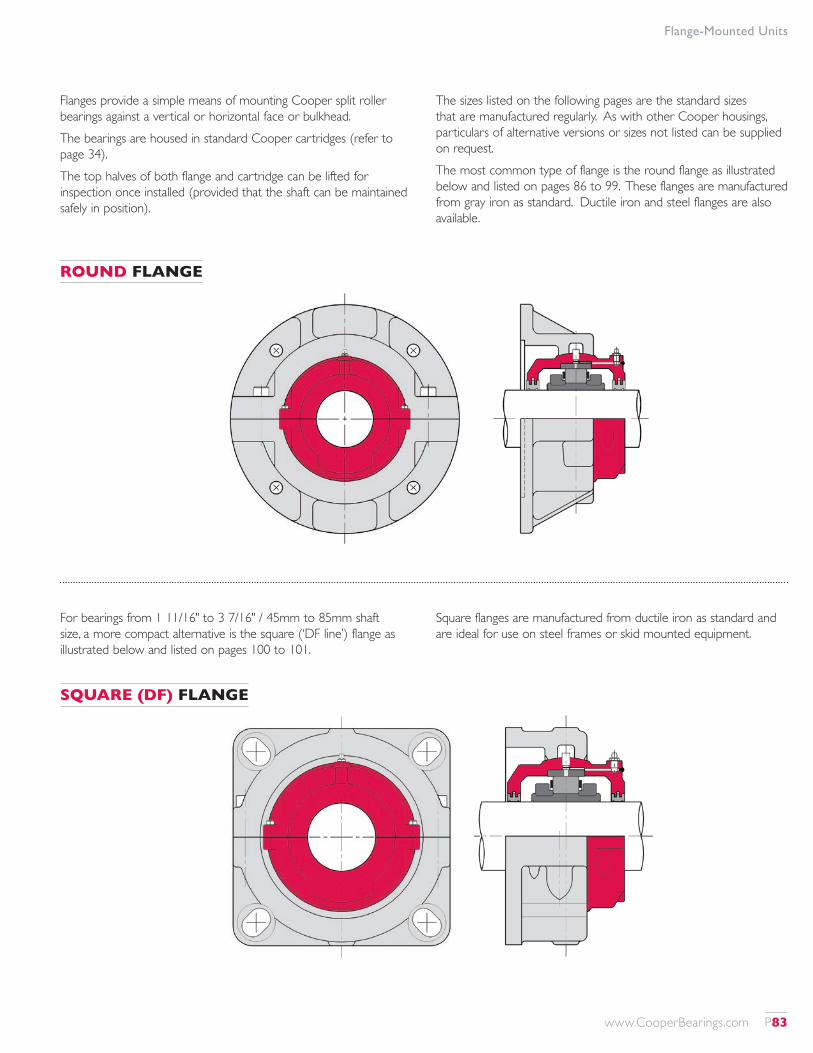
Flange-Mounted Units
Flanges provide a simple means of mounting Cooper split roller bearings against a vertical or horizontal face or bulkhead.The bearings are housed in standard Cooper cartridges (refer to page 34).The top halves of both flange and cartridge can be lifted for inspection once installed (provided that the shaft can be maintained safely in position).
The sizes listed on the following pages are the standard sizes that are manufactured regularly. As with other Cooper housings, particulars of alternative versions or sizes not listed can be supplied on request.The most common type of flange is the round flange as illustrated below and listed on pages 86 to 99. These flanges are manufactured from gray iron as standard. Ductile iron and steel flanges are also available.
For bearings from 1 11/16" to 3 7/16" / 45mm to 85mm shaft size, a more compact alternative is the square (‘DF line’) flange as illustrated below and listed on pages 100 to 101.
Square flanges are manufactured from ductile iron as standard and are ideal for use on steel frames or skid mounted equipment.
ROUND FLANGE
SQUARE (DF) FLANGE
www.CooperBearings.com P83
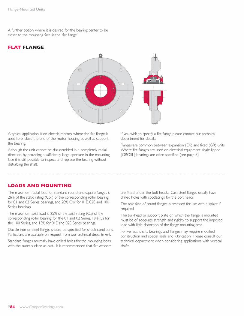
Flange-Mounted Units
A further option, where it is desired for the bearing center to be closer to the mounting face, is the 'flat flange'.
A typical application is on electric motors, where the flat flange is used to enclose the end of the motor housing as well as support the bearing.Although the unit cannot be disassembled in a completely radial direction, by providing a sufficiently large aperture in the mounting face it is still possible to inspect and replace the bearing without disturbing the shaft.
If you wish to specify a flat flange please contact our technical department for details.Flanges are common between expansion (EX) and fixed (GR) units. Where flat flanges are used on electrical equipment single lipped (GROSL) bearings are often specified (see page 5).
LOADS AND MOUNTINGThe maximum radial load for standard round and square flanges is 26% of the static rating (Cor) of the corresponding roller bearing for 01 and 02 Series bearings, and 20% Cor for 01E, 02E and 100 Series bearings.The maximum axial load is 25% of the axial rating (Ca) of the corresponding roller bearing for the 01 and 02 Series, 18% Ca for the 100 Series, and 13% for 01E and 02E Series bearings.Ductile iron or steel flanges should be specified for shock conditions. Particulars are available on request from our technical department.Standard flanges normally have drilled holes for the mounting bolts, with the outer surface as-cast. It is recommended that flat washers
are fitted under the bolt heads. Cast steel flanges usually have drilled holes with spotfacings for the bolt heads.The rear face of round flanges is recessed for use with a spigot if required.The bulkhead or support plate on which the flange is mounted must be of adequate strength and rigidity to support the imposed load with little distortion of the flange mounting area.For vertical shafts bearings and flanges may require modified construction and special seals and lubrication. Please consult our technical department when considering applications with vertical shafts.
FLAT FLANGE
P84 www.CooperBearings.com
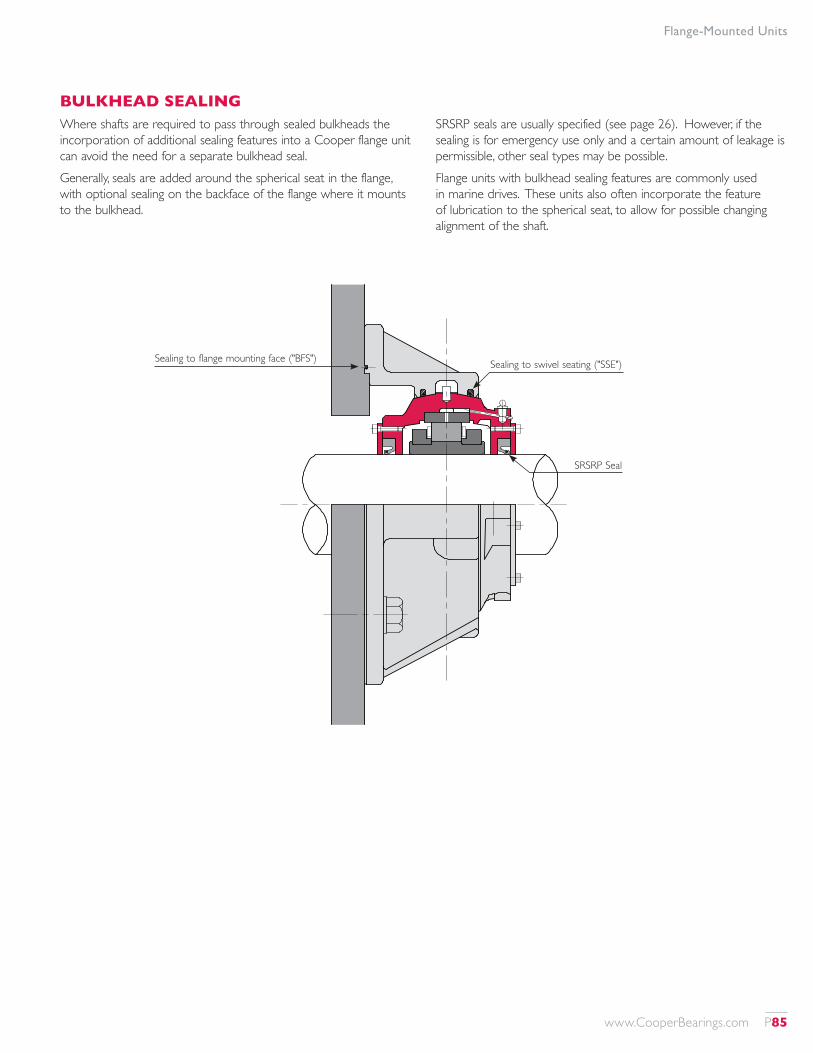
BULKHEAD SEALINGWhere shafts are required to pass through sealed bulkheads the incorporation of additional sealing features into a Cooper flange unit can avoid the need for a separate bulkhead seal.Generally, seals are added around the spherical seat in the flange, with optional sealing on the backface of the flange where it mounts to the bulkhead.
SRSRP seals are usually specified (see page 26). However, if the sealing is for emergency use only and a certain amount of leakage is permissible, other seal types may be possible.Flange units with bulkhead sealing features are commonly used in marine drives. These units also often incorporate the feature of lubrication to the spherical seat, to allow for possible changing alignment of the shaft.
Flange-Mounted Units
Sealing to flange mounting face ("BFS") Sealing to swivel seating ("SSE")
SRSRP Seal
www.CooperBearings.com P85
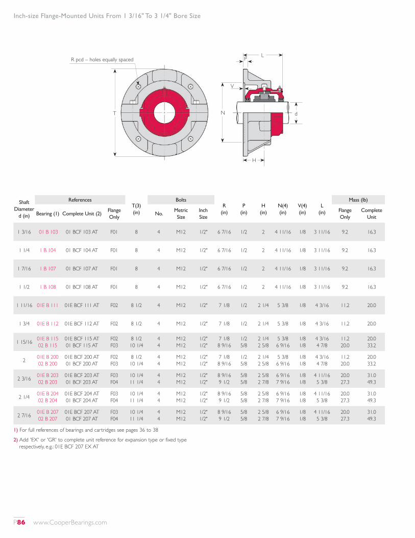
1) For full references of bearings and cartridges see pages 36 to 38
2) Add 'EX' or 'GR' to complete unit reference for expansion type or fixed type respectively, e.g.: 01E BCF 207 EX AT
Shaft Diameter
d (in)
ReferencesT(3) (in)
BoltsR
(in)P
(in)H
(in)N(4) (in)
V(4) (in)
L (in)
Mass (lb)
Bearing (1) Complete Unit (2)Flange Only
No.Metric Size
Inch Size
Flange Only
Complete Unit
1 3/16 01 B 103 01 BCF 103 AT F01 8 4 M12 1/2" 6 7/16 1/2 2 4 11/16 1/8 3 11/16 9.2 16.3
1 1/4 1 B 104 01 BCF 104 AT F01 8 4 M12 1/2" 6 7/16 1/2 2 4 11/16 1/8 3 11/16 9.2 16.3
1 7/16 1 B 107 01 BCF 107 AT F01 8 4 M12 1/2" 6 7/16 1/2 2 4 11/16 1/8 3 11/16 9.2 16.3
1 1/2 1 B 108 01 BCF 108 AT F01 8 4 M12 1/2" 6 7/16 1/2 2 4 11/16 1/8 3 11/16 9.2 16.3
1 11/16 01E B 111 01E BCF 111 AT F02 8 1/2 4 M12 1/2" 7 1/8 1/2 2 1/4 5 3/8 1/8 4 3/16 11.2 20.0
1 3/4 01E B 112 01E BCF 112 AT F02 8 1/2 4 M12 1/2" 7 1/8 1/2 2 1/4 5 3/8 1/8 4 3/16 11.2 20.0
1 15/16 01E B 115 02 B 115
01E BCF 115 AT 01 BCF 115 AT
F02 F03
8 1/2 10 1/4
4 4
M12 M12
1/2" 1/2"
7 1/8 8 9/16
1/2 5/8
2 1/4 2 5/8
5 3/8 6 9/16
1/8 1/8
4 3/16 4 7/8
11.2 20.0
20.0 33.2
2 01E B 200 02 B 200
01E BCF 200 AT 01 BCF 200 AT
F02 F03
8 1/2 10 1/4
4 4
M12 M12
1/2" 1/2"
7 1/8 8 9/16
1/2 5/8
2 1/4 2 5/8
5 3/8 6 9/16
1/8 1/8
4 3/16 4 7/8
11.2 20.0
20.0 33.2
2 3/16 01E B 203 02 B 203
01E BCF 203 AT 01 BCF 203 AT
F03 F04
10 1/4 11 1/4
4 4
M12 M12
1/2" 1/2"
8 9/16 9 1/2
5/8 5/8
2 5/8 2 7/8
6 9/16 7 9/16
1/8 1/8
4 11/16 5 3/8
20.0 27.3
31.0 49.3
2 1/4 01E B 204 02 B 204
01E BCF 204 AT 01 BCF 204 AT
F03 F04
10 1/4 11 1/4
4 4
M12 M12
1/2" 1/2"
8 9/16 9 1/2
5/8 5/8
2 5/8 2 7/8
6 9/16 7 9/16
1/8 1/8
4 11/16 5 3/8
20.0 27.3
31.0 49.3
2 7/16 01E B 207 02 B 207
01E BCF 207 AT 01 BCF 207 AT
F03 F04
10 1/4 11 1/4
4 4
M12 M12
1/2" 1/2"
8 9/16 9 1/2
5/8 5/8
2 5/8 2 7/8
6 9/16 7 9/16
1/8 1/8
4 11/16 5 3/8
20.0 27.3
31.0 49.3
Inch-size Flange-Mounted Units From 1 3/16" To 3 1/4" Bore Size
T
R pcd – holes equally spaced
N d
P
V
L
H
P86 www.CooperBearings.com

Shaft Diameter
d (in)
ReferencesT(3) (in)
BoltsR
(in)P
(in)H
(in)N(4) (in)
V(4) (in)
L (in)
Mass (lb)
Bearing (1) Complete Unit (2)Flange Only
No.Metric Size
Inch Size
Flange Only
Complete Unit
2 1/2 01E B 208 02 B 208
01E BCF 208 AT 02 BCF 208 AT
F03 F04
10 1/4 11 1/4
4 4
M12 M12
1/2" 1/2"
8 9/16 9 1/2
5/8 5/8
2 5/8 2 7/8
6 9/16 7 9/16
1/8 1/8
4 11/16 5 3/8
20.0 27.3
31.0 49.3
2 11/16 01E B 211 02 B 211
01E BCF 211 AT 02 BCF 211 AT
F04 F05
11 1/4 13
4 3
M12 M16
1/2" 5/8"
9 1/2 10 3/4
5/8 3/4
2 7/8 3 1/8
7 9/16 8 1/2
1/8 1/8
5 1/8 5 7/8
27.3 42.7
44.9 73.5
2 3/4 01E B 212 02 B 212
01E BCF 212 AT 02 BCF 212 AT
F04 F05
11 1/4 13
4 3
M12 M16
1/2" 5/8"
9 1/2 10 3/4
5/8 5/8
2 7/8 3 1/8
7 9/16 8 1/2
1/8 1/8
5 1/8 5 7/8
27.3 42.7
44.9 73.5
2 15/16100 B 215 01E B 215 02 B 215
100 BCF 215 AT 01E BCF 215 AT 02 BCF 215 AT
F03 F04 F05
10 1/4 11 1/4
13
4 4 4
M12 M12 M16
1/2" 1/2" 5/8"
8 9/16 9 1/2 10 3/4
5/8 5/8 3/4
2 5/8 2 7/8 3 1/8
6 9/16 7 9/16 8 1/2
1/8 1/8
4 11/16 5 1/8 5 7/8
20.0 27.3 42.7
30.6 44.9 73.5
3100 B 300 01E B 300 2 B 300
100 BCF 300 AT 01E BCF 300 AT 02 BCF 300 AT
F03 F04 F05
10 1/4 11 1/4
13
4 4 4
M12 M12 M16
1/2" 1/2" 5/8"
8 9/16 9 1/2 10 3/4
5/8 5/8 3/4
2 5/8 2 7/8 3 1/8
6 9/16 7 9/16 8 1/2
1/8 1/8
4 11/16 5 1/8 5 7/8
20.0 27.3 42.7
30.6 44.9 73.5
3 3/16 01E B 303 02 B 303
01E BCF 303 AT 02 BCF 303 AT
F05 F06
13 14
4 4
M16 M16
5/8" 5/8"
10 3/4 11 7/8
3/4 3/4
3 1/8 3 1/8
8 1/2 9 5/8
1/8 1/8
5 13/16 6 7/16
42.7 48.4
66.9 85.8
3 1/4 01E B 304 02 B 304
01E BCF 304 AT 02 BCF 304 AT
F05 F06
13 14
4 4
M16 M16
5/8" 5/8"
10 3/4 11 7/8
3/4 3/4
3 1/8 3 1/8
8 1/2 9 5/8
1/8 1/8
5 13/16 6 7/16
42.7 48.4
66.9 85.8
Inch-size Flange-Mounted Units From 1 3/16" To 3 1/4" Bore Size
3) Dimension shown is as-cast dimension. Depending upon manufacturing method used, flanges supplied may be machined 3/16" smaller.
4) Dimensions shown are for locating spigot for mounting flange on to. Diameter tolerance of locating spigot: f8
T
R pcd – holes equally spaced
N d
P
V
L
H
www.CooperBearings.com P87

1) For full references of bearings and cartridges see pages 40 to 44
2) Add 'EX' or 'GR' to complete unit reference for expansion type or fixed type respectively, e.g.: 01E BCF 307 EX AT
Shaft Diameter
d (in)
ReferencesT(3) (in)
BoltsR
(in)P
(in)H
(in)N(4) (in)
V(4) (in)
L (in)
Mass (lb)
Bearing (1) Complete Unit (2)Flange Only
No.Metric Size
Inch Size
Flange Only
Complete Unit
3 7/16100 B 307 01E B 307 2 B 307
100 BCF 307 AT 01E BCF 307 AT 02 BCF 307 AT
F04 F05 F06
11 1/4 13 14
4 4 4
M12 M16 M16
1/2" 5/8" 5/8"
9 1/2 10 3/4 11 7/8
5/8 3/4 3/4
2 7/8 3 1/8 3 3/8
7 9/16 8 1/2 9 5/8
1/8 1/8 1/8
5 1/8 5 13/16 6 7/16
27.3 42.7 48.4
43.8 66.9 85.8
3 1/2 01E B 308 02 B 308
01E BCF 308 AT 02 BCF 308 AT
F05 F06
13 14
4 4
M16 M16
5/8" 5/8"
10 3/4 11 7/8
3/4 3/4
3 1/8 3 3/8
8 1/2 9 5/8
1/8 1/8
5 13/16 6 7/16
42.7 48.4
66.9 85.8
3 11/16 01E B 311 02 B 311
01E BCF 311 AT 02 BCF 311 AT
F06 F07
14 15
4 4
M16 M16
5/8" 5/8"
11 7/8 13 1/8
3/4 7/8
3 3/8 3 5/8
9 5/8 10 7/8
1/8 1/8
6 6 1/2
48.4 58.5
79.2 105
3 3/4 01E B 312 02 B 312
01E BCF 312 AT 02 BCF 312 AT
F06 F07
14 15
4 4
M16 M16
5/8" 5/8"
11 7/8 13 1/8
3/4 7/8
3 3/8 3 5/8
9 5/8 10 7/8
1/8 1/8
6 6 1/2
48.4 58.5
79.2 105
3 15/16100 B 315 01E B 315 02 B 315
100 BCF 315 AT 01E BCF 315 AT 02 BCF 315 AT
F05 F06 F07
13 14 15
4 4 4
M16 M16 M16
5/8" 5/8" 5/8"
10 3/4 11 7/8 13 1/8
3/4 3/4 7/8
3 1/8 3 3/8 3 5/8
8 1/2 9 5/8 10 7/8
1/8 1/8 1/8
5 13/16 6
6 1/2
42.7 48.4 58.5
65.1 79.2 105
4 3/16 01 B 403 02 B 403
01E BCF 403 AT 02 BCF 403 AT
F07 F08
15 17
4 4
M16 M24
5/8" 1"
13 1/8 14 3/4
7/8 7/8
3 5/8 3 7/8
10 7/8 12 3/8
1/8 1/8
6 7/16 7 1/16
58.5 76.8
107 154
Inch-size Flange-Mounted Units From 3 7/16" To 5 3/16" Bore Size
T
R pcd – holes equally spaced
N d
P
V
L
H
P88 www.CooperBearings.com
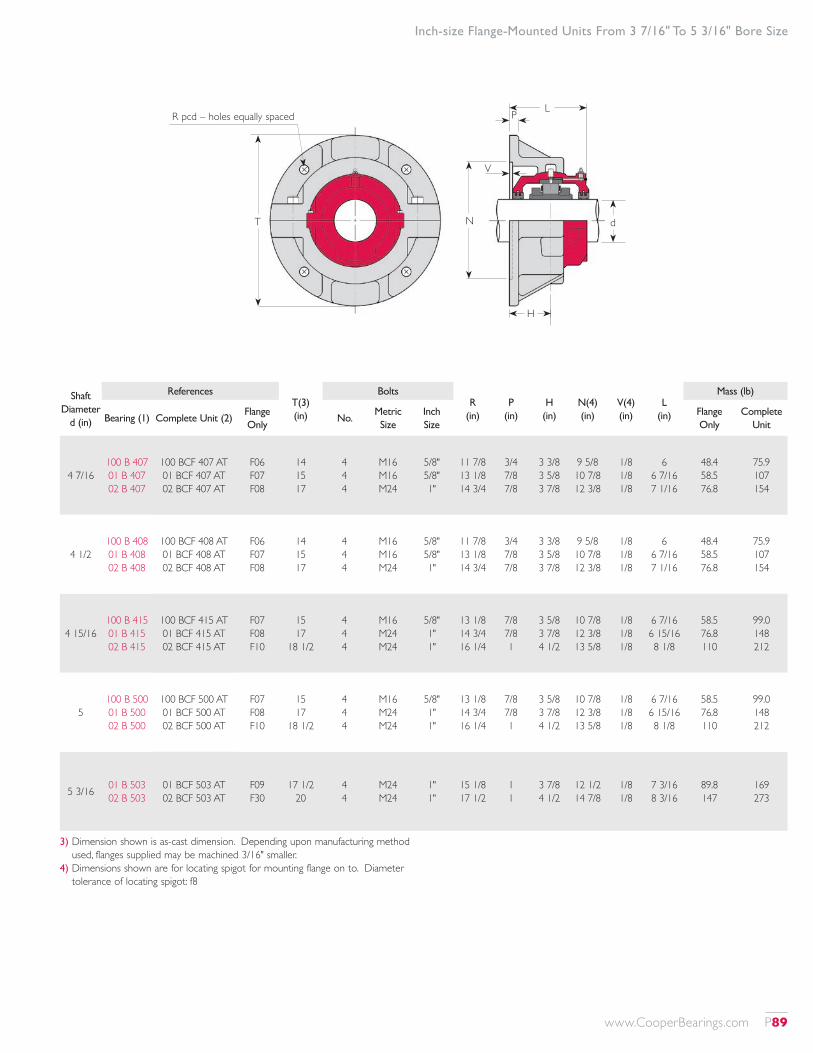
Shaft Diameter
d (in)
ReferencesT(3) (in)
BoltsR
(in)P
(in)H
(in)N(4) (in)
V(4) (in)
L (in)
Mass (lb)
Bearing (1) Complete Unit (2)Flange Only
No.Metric Size
Inch Size
Flange Only
Complete Unit
4 7/16100 B 407 01 B 407 02 B 407
100 BCF 407 AT 01 BCF 407 AT 02 BCF 407 AT
F06 F07 F08
14 15 17
4 4 4
M16 M16 M24
5/8" 5/8" 1"
11 7/8 13 1/8 14 3/4
3/4 7/8 7/8
3 3/8 3 5/8 3 7/8
9 5/8 10 7/8 12 3/8
1/8 1/8 1/8
6 6 7/16 7 1/16
48.4 58.5 76.8
75.9 107 154
4 1/2100 B 408 01 B 408 02 B 408
100 BCF 408 AT 01 BCF 408 AT 02 BCF 408 AT
F06 F07 F08
14 15 17
4 4 4
M16 M16 M24
5/8" 5/8" 1"
11 7/8 13 1/8 14 3/4
3/4 7/8 7/8
3 3/8 3 5/8 3 7/8
9 5/8 10 7/8 12 3/8
1/8 1/8 1/8
6 6 7/16 7 1/16
48.4 58.5 76.8
75.9 107 154
4 15/16100 B 415 01 B 415 02 B 415
100 BCF 415 AT 01 BCF 415 AT 02 BCF 415 AT
F07 F08 F10
15 17
18 1/2
4 4 4
M16 M24 M24
5/8" 1" 1"
13 1/8 14 3/4 16 1/4
7/8 7/8 1
3 5/8 3 7/8 4 1/2
10 7/8 12 3/8 13 5/8
1/8 1/8 1/8
6 7/16 6 15/16 8 1/8
58.5 76.8 110
99.0 148 212
5100 B 500 01 B 500 02 B 500
100 BCF 500 AT 01 BCF 500 AT 02 BCF 500 AT
F07 F08 F10
15 17
18 1/2
4 4 4
M16 M24 M24
5/8" 1" 1"
13 1/8 14 3/4 16 1/4
7/8 7/8 1
3 5/8 3 7/8 4 1/2
10 7/8 12 3/8 13 5/8
1/8 1/8 1/8
6 7/16 6 15/16 8 1/8
58.5 76.8 110
99.0 148 212
5 3/16 01 B 503 02 B 503
01 BCF 503 AT 02 BCF 503 AT
F09 F30
17 1/2 20
4 4
M24 M24
1" 1"
15 1/8 17 1/2
1 1
3 7/8 4 1/2
12 1/2 14 7/8
1/8 1/8
7 3/16 8 3/16
89.8 147
169 273
Inch-size Flange-Mounted Units From 3 7/16" To 5 3/16" Bore Size
3) Dimension shown is as-cast dimension. Depending upon manufacturing method used, flanges supplied may be machined 3/16" smaller.
4) Dimensions shown are for locating spigot for mounting flange on to. Diameter tolerance of locating spigot: f8
T
R pcd – holes equally spaced
N d
P
V
L
H
www.CooperBearings.com P89
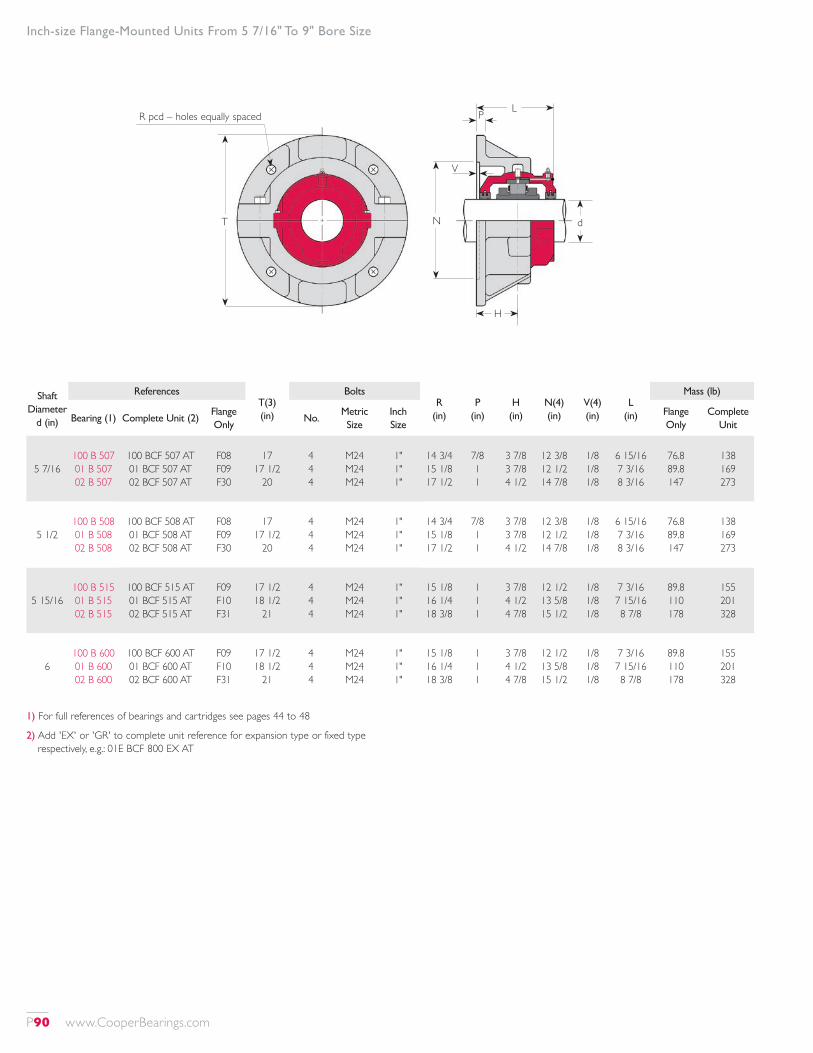
1) For full references of bearings and cartridges see pages 44 to 48
2) Add 'EX' or 'GR' to complete unit reference for expansion type or fixed type respectively, e.g.: 01E BCF 800 EX AT
Shaft Diameter
d (in)
ReferencesT(3) (in)
BoltsR
(in)P
(in)H
(in)N(4) (in)
V(4) (in)
L (in)
Mass (lb)
Bearing (1) Complete Unit (2)Flange Only
No.Metric Size
Inch Size
Flange Only
Complete Unit
5 7/16100 B 507 01 B 507 02 B 507
100 BCF 507 AT 01 BCF 507 AT 02 BCF 507 AT
F08 F09 F30
17 17 1/2
20
4 4 4
M24 M24 M24
1" 1" 1"
14 3/4 15 1/8 17 1/2
7/8 1 1
3 7/8 3 7/8 4 1/2
12 3/8 12 1/2 14 7/8
1/8 1/8 1/8
6 15/16 7 3/16 8 3/16
76.8 89.8 147
138 169 273
5 1/2100 B 508 01 B 508 02 B 508
100 BCF 508 AT 01 BCF 508 AT 02 BCF 508 AT
F08 F09 F30
17 17 1/2
20
4 4 4
M24 M24 M24
1" 1" 1"
14 3/4 15 1/8 17 1/2
7/8 1 1
3 7/8 3 7/8 4 1/2
12 3/8 12 1/2 14 7/8
1/8 1/8 1/8
6 15/16 7 3/16 8 3/16
76.8 89.8 147
138 169 273
5 15/16100 B 515 01 B 515 02 B 515
100 BCF 515 AT 01 BCF 515 AT 02 BCF 515 AT
F09 F10 F31
17 1/2 18 1/2
21
4 4 4
M24 M24 M24
1" 1" 1"
15 1/8 16 1/4 18 3/8
1 1 1
3 7/8 4 1/2 4 7/8
12 1/2 13 5/8 15 1/2
1/8 1/8 1/8
7 3/16 7 15/16 8 7/8
89.8 110 178
155 201 328
6100 B 600 01 B 600 02 B 600
100 BCF 600 AT 01 BCF 600 AT 02 BCF 600 AT
F09 F10 F31
17 1/2 18 1/2
21
4 4 4
M24 M24 M24
1" 1" 1"
15 1/8 16 1/4 18 3/8
1 1 1
3 7/8 4 1/2 4 7/8
12 1/2 13 5/8 15 1/2
1/8 1/8 1/8
7 3/16 7 15/16 8 7/8
89.8 110 178
155 201 328
Inch-size Flange-Mounted Units From 5 7/16" To 9" Bore Size
T
R pcd – holes equally spaced
N d
P
V
L
H
P90 www.CooperBearings.com
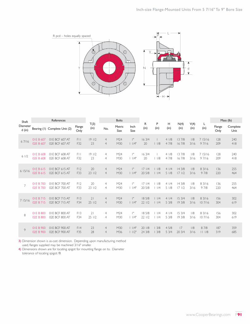
Shaft Diameter
d (in)
ReferencesT(3) (in)
BoltsR
(in)P
(in)H
(in)N(4) (in)
V(4) (in)
L (in)
Mass (lb)
Bearing (1) Complete Unit (2)Flange Only
No.Metric Size
Inch Size
Flange Only
Complete Unit
6 7/16 01E B 607 02E B 607
01E BCF 607 AT 02E BCF 607 AT
F11 F32
19 1/2 23
4 4
M24 M30
1" 1 1/4"
16 3/4 20
1 1 1/8
4 1/8 4 7/8
13 7/8 16 7/8
1/8 3/16
7 15/16 9 7/16
128 209
240 418
6 1/2 01E B 608 02E B 608
01E BCF 608 AT 02E BCF 608 AT
F11 F32
19 1/2 23
4 4
M24 M30
1" 1 1/4"
16 3/4 20
1 1 1/8
4 1/8 4 7/8
13 7/8 16 7/8
1/8 3/16
7 15/16 9 7/16
128 209
240 418
6 15/16 01E B 615 02E B 615
01E BCF 615 AT 02E BCF 615 AT
F12 F33
20 23 1/2
4 4
M24 M30
1" 1 1/4"
17 1/4 20 5/8
1 1/8 1 1/4
4 1/4 5 1/8
14 3/8 17 1/2
1/8 3/16
8 3/16 9 7/8
136 220
255 464
7 01E B 700 02E B 700
01E BCF 700 AT 02E BCF 700 AT
F12 F33
20 23 1/2
4 4
M24 M30
1" 1 1/4"
17 1/4 20 5/8
1 1/8 1 1/4
4 1/4 5 1/8
14 3/8 17 1/2
1/8 3/16
8 3/16 9 7/8
136 220
255 464
7 15/16 01E B 715 02E B 715
01E BCF 715 AT 02E BCF 715 AT
F13 F34
21 25 1/2
4 4
M24 M30
1" 1 1/4"
18 5/8 22 1/2
1 1/4 1 1/4
4 1/4 5 3/8
15 3/4 19 3/8
1/8 3/16
8 3/16 10 7/16
156 304
302 619
8 01E B 800 02E B 800
01E BCF 800 AT 02E BCF 800 AT
F13 F34
21 25 1/2
4 4
M24 M30
1" 1 1/4"
18 5/8 22 1/2
1 1/4 1 1/4
4 1/4 5 3/8
15 3/4 19 3/8
1/8 3/16
8 3/16 10 7/16
156 304
302 619
9 01E B 900 02E B 900
01E BCF 900 AT 02E BCF 900 AT
F14 F35
23 28
4 4
M30 M36
1 1/4" 1 1/2"
20 1/8 24 3/8
1 3/8 1 3/8
4 5/8 5 3/4
17 20 3/4
1/8 3/16
8 7/8 11 1/8
187 319
359 685
Inch-size Flange-Mounted Units From 5 7/16" To 9" Bore Size
3) Dimension shown is as-cast dimension. Depending upon manufacturing method used, flanges supplied may be machined 3/16" smaller.
4) Dimensions shown are for locating spigot for mounting flange on to. Diameter tolerance of locating spigot: f8
T
R pcd – holes equally spaced
N d
P
V
L
H
www.CooperBearings.com P91
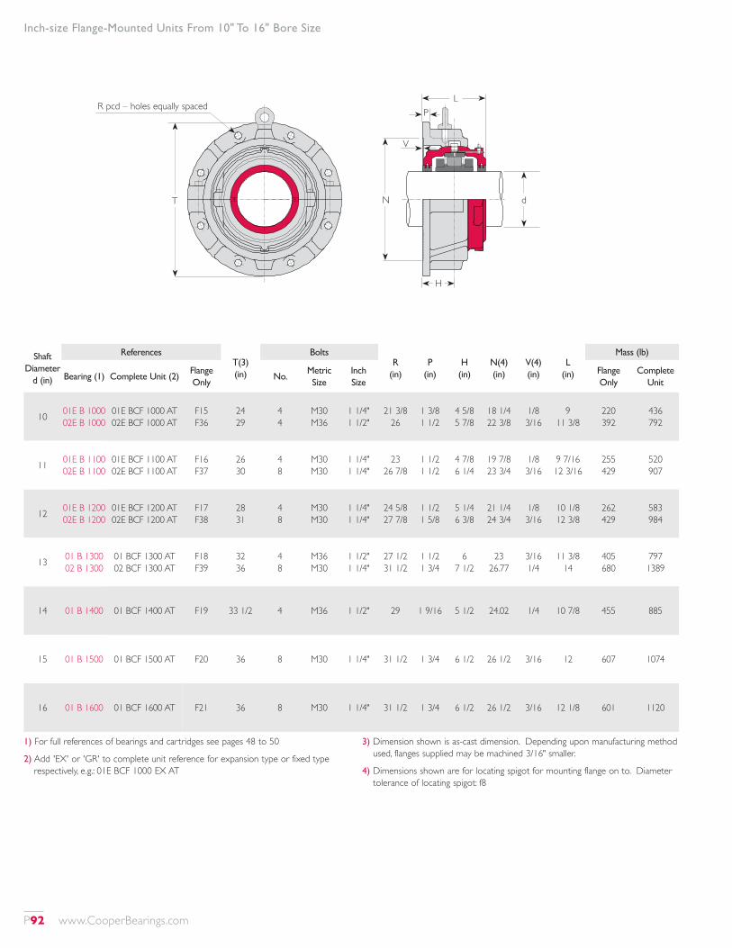
1) For full references of bearings and cartridges see pages 48 to 50
2) Add 'EX' or 'GR' to complete unit reference for expansion type or fixed type respectively, e.g.: 01E BCF 1000 EX AT
3) Dimension shown is as-cast dimension. Depending upon manufacturing method used, flanges supplied may be machined 3/16" smaller.
4) Dimensions shown are for locating spigot for mounting flange on to. Diameter tolerance of locating spigot: f8
Shaft Diameter
d (in)
ReferencesT(3) (in)
BoltsR
(in)P
(in)H
(in)N(4) (in)
V(4) (in)
L (in)
Mass (lb)
Bearing (1) Complete Unit (2)Flange Only
No.Metric Size
Inch Size
Flange Only
Complete Unit
10 01E B 1000 02E B 1000
01E BCF 1000 AT 02E BCF 1000 AT
F15 F36
24 29
4 4
M30 M36
1 1/4" 1 1/2"
21 3/8 26
1 3/8 1 1/2
4 5/8 5 7/8
18 1/4 22 3/8
1/8 3/16
9 11 3/8
220 392
436 792
11 01E B 1100 02E B 1100
01E BCF 1100 AT 02E BCF 1100 AT
F16 F37
26 30
4 8
M30 M30
1 1/4" 1 1/4"
23 26 7/8
1 1/2 1 1/2
4 7/8 6 1/4
19 7/8 23 3/4
1/8 3/16
9 7/16 12 3/16
255 429
520 907
12 01E B 1200 02E B 1200
01E BCF 1200 AT 02E BCF 1200 AT
F17 F38
28 31
4 8
M30 M30
1 1/4" 1 1/4"
24 5/8 27 7/8
1 1/2 1 5/8
5 1/4 6 3/8
21 1/4 24 3/4
1/8 3/16
10 1/8 12 3/8
262 429
583 984
13 01 B 1300 02 B 1300
01 BCF 1300 AT 02 BCF 1300 AT
F18 F39
32 36
4 8
M36 M30
1 1/2" 1 1/4"
27 1/2 31 1/2
1 1/2 1 3/4
6 7 1/2
23 26.77
3/16 1/4
11 3/8 14
405 680
797 1389
14 01 B 1400 01 BCF 1400 AT F19 33 1/2 4 M36 1 1/2" 29 1 9/16 5 1/2 24.02 1/4 10 7/8 455 885
15 01 B 1500 01 BCF 1500 AT F20 36 8 M30 1 1/4" 31 1/2 1 3/4 6 1/2 26 1/2 3/16 12 607 1074
16 01 B 1600 01 BCF 1600 AT F21 36 8 M30 1 1/4" 31 1/2 1 3/4 6 1/2 26 1/2 3/16 12 1/8 601 1120
Inch-size Flange-Mounted Units From 10" To 16" Bore Size
T
R pcd – holes equally spaced
N d
P
V
L
H
P92 www.CooperBearings.com
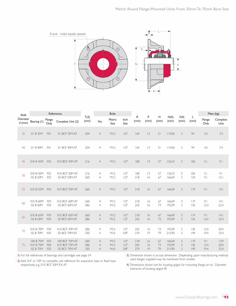
1) For full references of bearings and cartridges see page 54
2) Add 'EX' or 'GR' to complete unit reference for expansion type or fixed type respectively, e.g.: 01E BCF 50M EX AT
3) Dimension shown is as-cast dimension. Depending upon manufacturing method used, flanges supplied may be machined 5mm smaller.
4) Dimensions shown are for locating spigot for mounting flange on to. Diameter tolerance of locating spigot: f8
Shaft Diameter d (mm)
ReferencesT(3) (mm)
BoltsR
(mm)P
(mm)H
(mm)N(4) (mm)
V(4) (mm)
L (mm)
Mass (kg)
Bearing (1)Flange Only
Complete Unit (2) No.Metric Size
Inch Size
Flange Only
Complete Unit
35 01 B 35M F01 01 BCF 35M AT 204 4 M12 1/2" 164 13 51 119.06 3 94 4.2 7.4
40 01 B 40M F01 01 BCF 40M AT 204 4 M12 1/2" 164 13 51 119.06 3 94 4.2 7.4
45 01E B 45M F02 01E BCF 45M AT 216 4 M12 1/2" 180 13 57 136.53 3 106 5.1 9.1
50 01E B 50M 02 B 50M
F02 F03
01E BCF 50M AT 02 BCF 50M AT
216 260
4 4
M12 M12
1/2" 1/2"
180 218
13 16
57 67
136.53 166.69
3 3
106 124
5.1 9.1
9.1 15.1
55 01E B 55M F03 01E BCF 55M AT 260 4 M12 1/2" 218 16 67 166.69 3 119 9.1 14.1
60 01E B 60M 02 B 60M
F03 F04
01E BCF 60M AT 02 BCF 60M AT
260 286
4 4
M12 M12
1/2" 1/2"
218 242
16 16
67 73
166.69 192.09
3 3
119 136
9.1 12.4
14.1 22.4
65 01E B 65M 02 B 65M
F03 F04
01E BCF 65M AT 02 BCF 65M AT
260 286
4 4
M12 M12
1/2" 1/2"
218 242
16 16
67 73
166.69 192.09
3 3
119 136
9.1 12.4
14.1 22.4
70 01E B 70M 02 B 70M
F04 F05
01E BCF 70M AT 02 BCF 70M AT
286 330
4 4
M12 M16
1/2" 5/8"
242 274
16 19
73 79
192.09 215.90
3 3
130 149
12.4 19.4
20.4 33.4
75100 B 75M 01E B 75M 02 B 75M
F03 F04 F05
100 BCF 75M AT 01E BCF 75M AT 02 BCF 75M AT
260 286 330
4 4 4
M12 M12 M16
1/2" 1/2" 5/8"
218 242 274
16 16 19
67 73 79
166.69 192.09 215.90
3 3 3
119 130 149
9.1 12.4 19.4
13.9 20.4 33.4
Metric Round Flange-Mounted Units From 35mm To 75mm Bore Size
T
R pcd – holes equally spaced
N d
P
V
L
H
www.CooperBearings.com P93
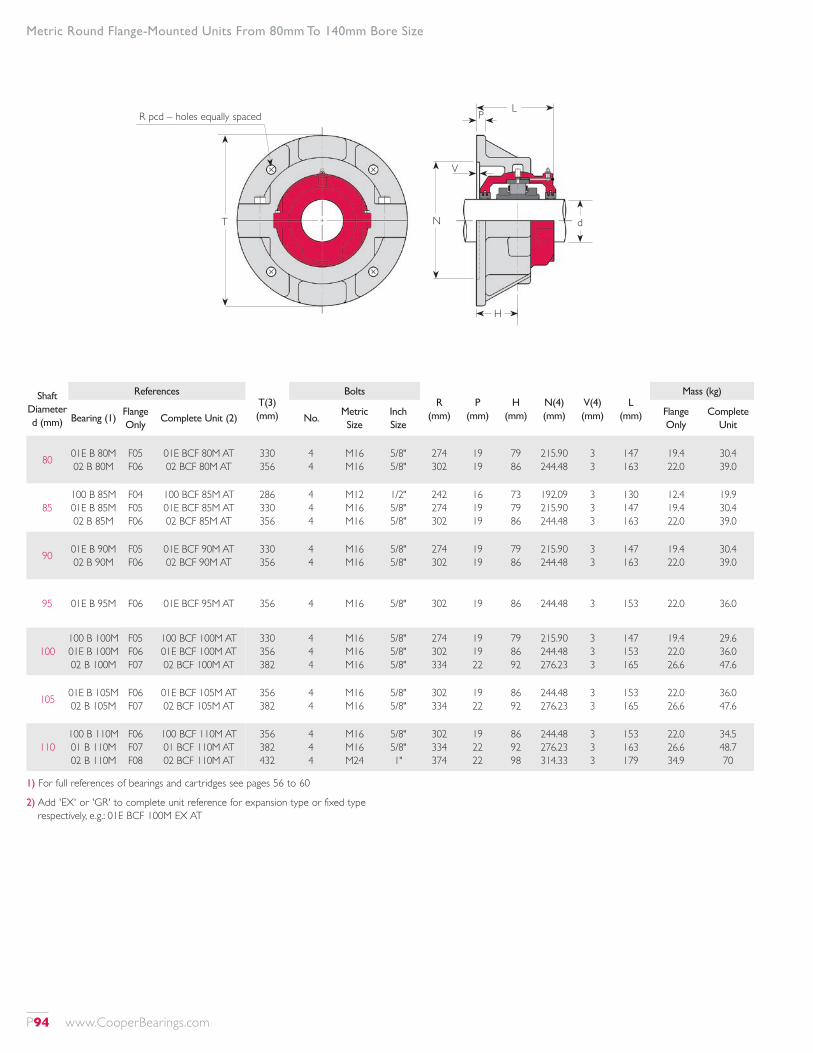
1) For full references of bearings and cartridges see pages 56 to 60
2) Add 'EX' or 'GR' to complete unit reference for expansion type or fixed type respectively, e.g.: 01E BCF 100M EX AT
Shaft Diameter d (mm)
ReferencesT(3) (mm)
BoltsR
(mm)P
(mm)H
(mm)N(4) (mm)
V(4) (mm)
L (mm)
Mass (kg)
Bearing (1)Flange Only
Complete Unit (2) No.Metric Size
Inch Size
Flange Only
Complete Unit
80 01E B 80M 02 B 80M
F05 F06
01E BCF 80M AT 02 BCF 80M AT
330 356
4 4
M16 M16
5/8" 5/8"
274 302
19 19
79 86
215.90 244.48
3 3
147 163
19.4 22.0
30.4 39.0
85100 B 85M 01E B 85M 02 B 85M
F04 F05 F06
100 BCF 85M AT 01E BCF 85M AT 02 BCF 85M AT
286 330 356
4 4 4
M12 M16 M16
1/2" 5/8" 5/8"
242 274 302
16 19 19
73 79 86
192.09 215.90 244.48
3 3 3
130 147 163
12.4 19.4 22.0
19.9 30.4 39.0
90 01E B 90M 02 B 90M
F05 F06
01E BCF 90M AT 02 BCF 90M AT
330 356
4 4
M16 M16
5/8" 5/8"
274 302
19 19
79 86
215.90 244.48
3 3
147 163
19.4 22.0
30.4 39.0
95 01E B 95M F06 01E BCF 95M AT 356 4 M16 5/8" 302 19 86 244.48 3 153 22.0 36.0
100100 B 100M 01E B 100M 02 B 100M
F05 F06 F07
100 BCF 100M AT 01E BCF 100M AT 02 BCF 100M AT
330 356 382
4 4 4
M16 M16 M16
5/8" 5/8" 5/8"
274 302 334
19 19 22
79 86 92
215.90 244.48 276.23
3 3 3
147 153 165
19.4 22.0 26.6
29.6 36.0 47.6
105 01E B 105M 02 B 105M
F06 F07
01E BCF 105M AT 02 BCF 105M AT
356 382
4 4
M16 M16
5/8" 5/8"
302 334
19 22
86 92
244.48 276.23
3 3
153 165
22.0 26.6
36.0 47.6
110100 B 110M 01 B 110M 02 B 110M
F06 F07 F08
100 BCF 110M AT 01 BCF 110M AT 02 BCF 110M AT
356 382 432
4 4 4
M16 M16 M24
5/8" 5/8" 1"
302 334 374
19 22 22
86 92 98
244.48 276.23 314.33
3 3 3
153 163 179
22.0 26.6 34.9
34.5 48.7 70
Metric Round Flange-Mounted Units From 80mm To 140mm Bore Size
T
R pcd – holes equally spaced
N d
P
V
L
H
P94 www.CooperBearings.com
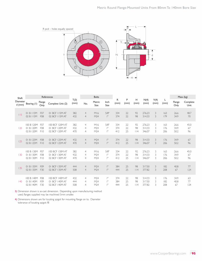
3) Dimension shown is as-cast dimension. Depending upon manufacturing method used, flanges supplied may be machined 5mm smaller.
4) Dimensions shown are for locating spigot for mounting flange on to. Diameter tolerance of locating spigot: f8
Shaft Diameter d (mm)
ReferencesT(3) (mm)
BoltsR
(mm)P
(mm)H
(mm)N(4) (mm)
V(4) (mm)
L (mm)
Mass (kg)
Bearing (1)Flange Only
Complete Unit (2) No.Metric Size
Inch Size
Flange Only
Complete Unit
115 01 B 115M 02 B 115M
F07 F08
01 BCF 115M AT 02 BCF 115M AT
382 432
4 4
M16 M24
5/8" 1"
334 374
22 22
92 98
276.23 314.33
3 3
163 179
26.6 34.9
48.7 70
120100 B 120M 01 B 120M 02 B 120M
F07 F08 F10
100 BCF 120M AT 01 BCF 120M AT 02 BCF 120M AT
382 432 470
4 4 4
M16 M24 M24
5/8" 1" 1"
334 374 412
22 22 25
92 98 114
276.23 314.33 346.07
3 3 3
163 176 206
26.6 34.9 50.2
45.0 67 96
125 01 B 125M 02 B 125M
F08 F10
01 BCF 125M AT 02 BCF 125M AT
432 470
4 4
M24 M24
1" 1"
374 412
22 25
98 114
314.33 346.07
3 3
176 206
34.9 50.2
67 96
130100 B 130M 01 B 130M 02 B 130M
F07 F08 F10
100 BCF 130M AT 01 BCF 130M AT 02 BCF 130M AT
382 432 470
4 4 4
M16 M24 M24
5/8" 1" 1"
334 374 412
22 22 25
92 98 114
276.23 314.33 346.07
3 3 3
163 176 206
26.6 34.9 50.2
45.0 67 96
135 01 B 135M 02 B 135M
F09 F30
01 BCF 135M AT 02 BCF 135M AT
444 508
4 4
M24 M24
1" 1"
384 444
25 25
98 114
317.50 377.82
3 3
182 208
40.8 67
77 124
140100 B 140M 01 B 140M 02 B 140M
F08 F09 F30
100 BCF 140M AT 01 BCF 140M AT 02 BCF 140M AT
432 444 508
4 4 4
M24 M24 M24
1" 1" 1"
374 384 444
22 25 25
98 98 114
314.33 317.50 377.82
3 3 3
176 182 208
34.9 40.8 67
63 77 124
Metric Round Flange-Mounted Units From 80mm To 140mm Bore Size
T
R pcd – holes equally spaced
N d
P
V
L
H
www.CooperBearings.com P95
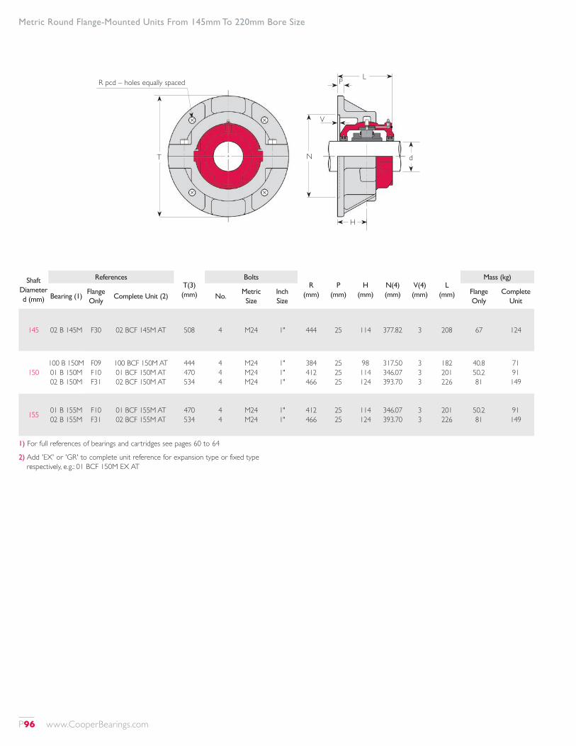
1) For full references of bearings and cartridges see pages 60 to 64
2) Add 'EX' or 'GR' to complete unit reference for expansion type or fixed type respectively, e.g.: 01 BCF 150M EX AT
Shaft Diameter d (mm)
ReferencesT(3) (mm)
BoltsR
(mm)P
(mm)H
(mm)N(4) (mm)
V(4) (mm)
L (mm)
Mass (kg)
Bearing (1)Flange Only
Complete Unit (2) No.Metric Size
Inch Size
Flange Only
Complete Unit
145 02 B 145M F30 02 BCF 145M AT 508 4 M24 1" 444 25 114 377.82 3 208 67 124
150100 B 150M 01 B 150M 02 B 150M
F09 F10 F31
100 BCF 150M AT 01 BCF 150M AT 02 BCF 150M AT
444 470 534
4 4 4
M24 M24 M24
1" 1" 1"
384 412 466
25 25 25
98 114 124
317.50 346.07 393.70
3 3 3
182 201 226
40.8 50.2 81
71 91 149
155 01 B 155M 02 B 155M
F10 F31
01 BCF 155M AT 02 BCF 155M AT
470 534
4 4
M24 M24
1" 1"
412 466
25 25
114 124
346.07 393.70
3 3
201 226
50.2 81
91 149
Metric Round Flange-Mounted Units From 145mm To 220mm Bore Size
T
R pcd – holes equally spaced
N d
P
V
L
H
P96 www.CooperBearings.com
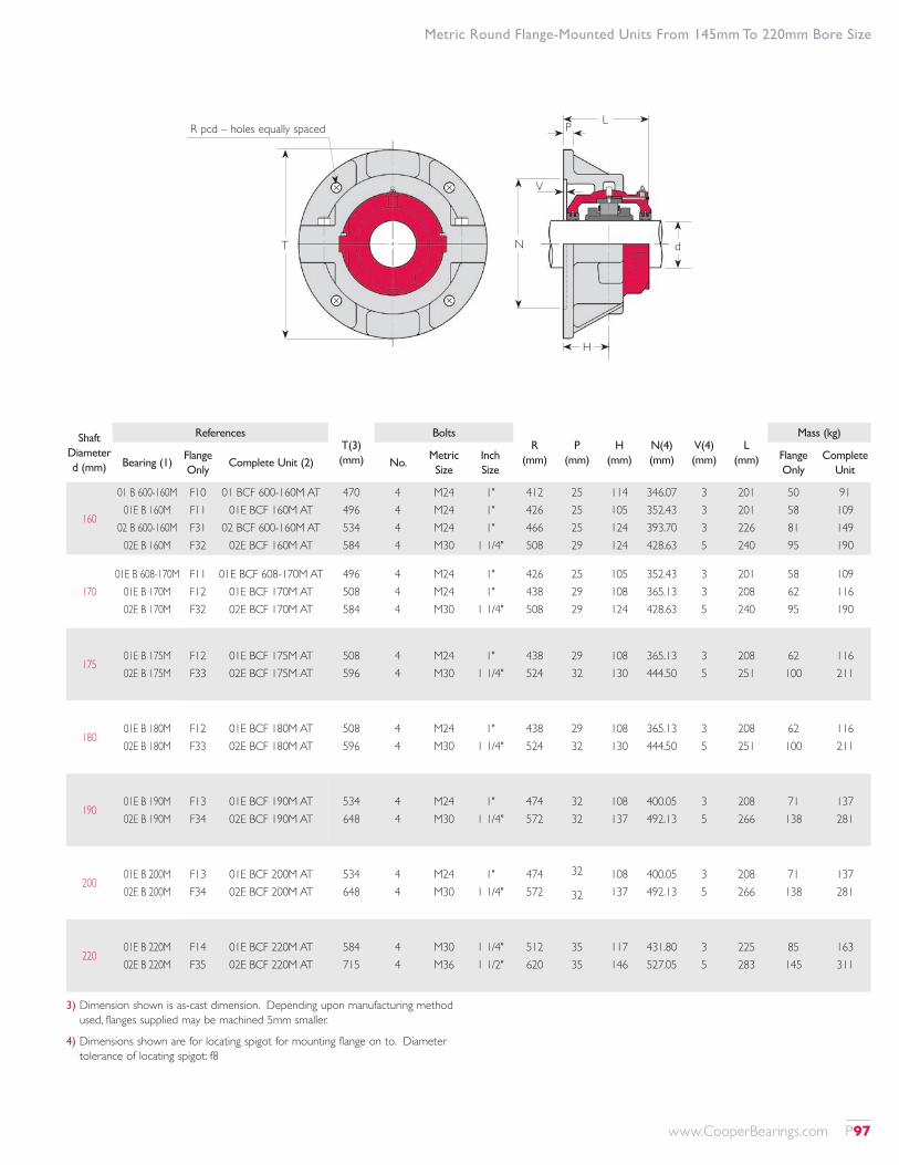
3) Dimension shown is as-cast dimension. Depending upon manufacturing method used, flanges supplied may be machined 5mm smaller.
4) Dimensions shown are for locating spigot for mounting flange on to. Diameter tolerance of locating spigot: f8
Shaft Diameter d (mm)
ReferencesT(3) (mm)
BoltsR
(mm)P
(mm)H
(mm)N(4) (mm)
V(4) (mm)
L (mm)
Mass (kg)
Bearing (1)Flange Only
Complete Unit (2) No.Metric Size
Inch Size
Flange Only
Complete Unit
160
01 B 600-160M 01E B 160M
02 B 600-160M 02E B 160M
F10 F11 F31 F32
01 BCF 600-160M AT 01E BCF 160M AT
02 BCF 600-160M AT 02E BCF 160M AT
470 496 534 584
4 4 4 4
M24 M24 M24 M30
1" 1" 1"
1 1/4"
412 426 466 508
25 25 25 29
114 105 124 124
346.07 352.43 393.70 428.63
3 3 3 5
201 201 226 240
50 58 81 95
91 109 149 190
17001E B 608-170M
01E B 170M 02E B 170M
F11 F12 F32
01E BCF 608-170M AT 01E BCF 170M AT 02E BCF 170M AT
496 508 584
4 4 4
M24 M24 M30
1" 1"
1 1/4"
426 438 508
25 29 29
105 108 124
352.43 365.13 428.63
3 3 5
201 208 240
58 62 95
109 116 190
17501E B 175M 02E B 175M
F12 F33
01E BCF 175M AT 02E BCF 175M AT
508 596
4 4
M24 M30
1" 1 1/4"
438 524
29 32
108 130
365.13 444.50
3 5
208 251
62 100
116 211
18001E B 180M 02E B 180M
F12 F33
01E BCF 180M AT 02E BCF 180M AT
508 596
4 4
M24 M30
1" 1 1/4"
438 524
29 32
108 130
365.13 444.50
3 5
208 251
62 100
116 211
19001E B 190M 02E B 190M
F13 F34
01E BCF 190M AT 02E BCF 190M AT
534 648
4 4
M24 M30
1" 1 1/4"
474 572
32 32
108 137
400.05 492.13
3 5
208 266
71 138
137 281
20001E B 200M 02E B 200M
F13 F34
01E BCF 200M AT 02E BCF 200M AT
534 648
4 4
M24 M30
1" 1 1/4"
474 572
32
32
108 137
400.05 492.13
3 5
208 266
71 138
137 281
22001E B 220M 02E B 220M
F14 F35
01E BCF 220M AT 02E BCF 220M AT
584 715
4 4
M30 M36
1 1/4" 1 1/2"
512 620
35 35
117 146
431.80 527.05
3 5
225 283
85 145
163 311
Metric Round Flange-Mounted Units From 145mm To 220mm Bore Size
T
R pcd – holes equally spaced
N d
P
V
L
H
www.CooperBearings.com P97
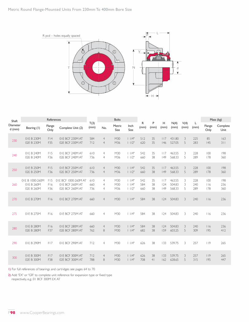
1) For full references of bearings and cartridges see pages 64 to 70
2) Add 'EX' or 'GR' to complete unit reference for expansion type or fixed type respectively, e.g.: 01 BCF 300M EX AT
Shaft Diameter d (mm)
ReferencesT(3) (mm)
BoltsR
(mm)P
(mm)H
(mm)N(4) (mm)
V(4) (mm)
L (mm)
Mass (kg)
Bearing (1)Flange Only
Complete Unit (2) No.Metric Size
Inch Size
Flange Only
Complete Unit
230 01E B 230M 02E B 230M
F14 F35
01E BCF 230M AT 02E BCF 230M AT
584 712
4 4
M30 M36
1 1/4" 1 1/2"
512 620
35 35
117 146
431.80 527.05
3 5
225 283
85 145
163 311
240 01E B 240M 02E B 240M
F15 F36
01E BCF 240M AT 02E BCF 240M AT
610 736
4 4
M30 M36
1 1/4" 1 1/2"
542 660
35 38
117 149
463.55 568.33
3 5
228 289
100 178
198 360
250 01E B 250M 02E B 250M
F15 F36
01E BCF 250M AT 02E BCF 250M AT
610 736
4 4
M30 M36
1 1/4" 1 1/2"
542 660
35 38
117 149
463.55 568.33
3 5
228 289
100 178
198 360
26001E B 1000-260M
01E B 260M 02E B 260M
F15 F16 F36
01E BCF 1000-260M AT 01E BCF 260M AT 02E BCF 260M AT
610 660 736
4 4 4
M30 M30 M36
1 1/4" 1 1/4" 1 1/2"
542 584 660
35 38 38
117 124 149
463.55 504.83 568.33
3 3 5
228 240 289
100 116 178
198 236 360
270 01E B 270M F16 01E BCF 270M AT 660 4 M30 1 1/4" 584 38 124 504.83 3 240 116 236
275 01E B 275M F16 01E BCF 275M AT 660 4 M30 1 1/4" 584 38 124 504.83 3 240 116 236
280 01E B 280M 02E B 280M
F16 F37
01E BCF 280M AT 02E BCF 280M AT
660 762
4 8
M30 M30
1 1/4" 1 1/4"
584 682
38 38
124 159
504.83 603.25
3 5
240 309
116 195
236 412
290 01E B 290M F17 01E BCF 290M AT 712 4 M30 1 1/4" 626 38 133 539.75 3 257 119 265
300 01E B 300M 02E B 300M
F17 F38
01E BCF 300M AT 02E BCF 300M AT
712 788
4 8
M30 M30
1 1/4" 1 1/4"
626 708
38 41
133 162
539.75 628.65
3 5
257 315
119 195
265 447
Metric Round Flange-Mounted Units From 230mm To 400mm Bore Size
T
R pcd – holes equally spaced
N d
P
V
L
H
P98 www.CooperBearings.com
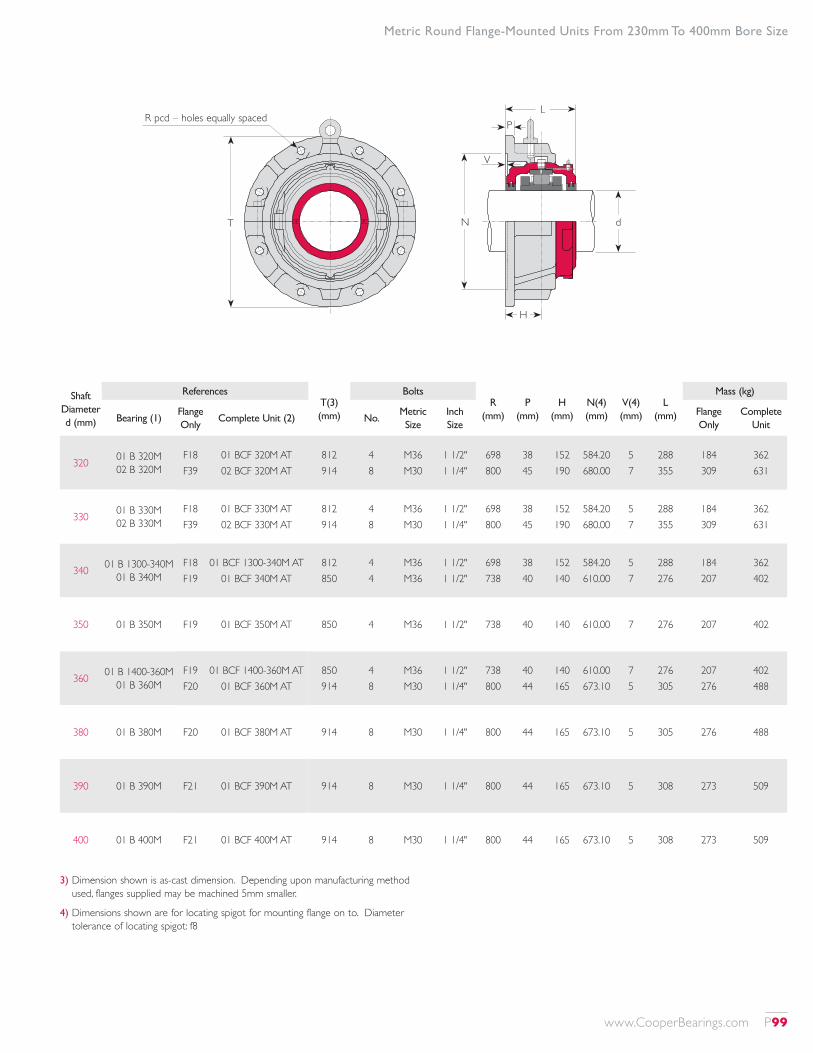
3) Dimension shown is as-cast dimension. Depending upon manufacturing method used, flanges supplied may be machined 5mm smaller.
4) Dimensions shown are for locating spigot for mounting flange on to. Diameter tolerance of locating spigot: f8
Shaft Diameter d (mm)
ReferencesT(3) (mm)
BoltsR
(mm)P
(mm)H
(mm)N(4) (mm)
V(4) (mm)
L (mm)
Mass (kg)
Bearing (1)Flange Only
Complete Unit (2) No.Metric Size
Inch Size
Flange Only
Complete Unit
320 01 B 320M 02 B 320M
F18 F39
01 BCF 320M AT 02 BCF 320M AT
812 914
4 8
M36 M30
1 1/2" 1 1/4"
698 800
38 45
152 190
584.20 680.00
5 7
288 355
184 309
362 631
330 01 B 330M 02 B 330M
F18 F39
01 BCF 330M AT 02 BCF 330M AT
812 914
4 8
M36 M30
1 1/2" 1 1/4"
698 800
38 45
152 190
584.20 680.00
5 7
288 355
184 309
362 631
340 01 B 1300-340M 01 B 340M
F18 F19
01 BCF 1300-340M AT 01 BCF 340M AT
812 850
4 4
M36 M36
1 1/2" 1 1/2"
698 738
38 40
152 140
584.20 610.00
5 7
288 276
184 207
362 402
350 01 B 350M F19 01 BCF 350M AT 850 4 M36 1 1/2" 738 40 140 610.00 7 276 207 402
360 01 B 1400-360M 01 B 360M
F19 F20
01 BCF 1400-360M AT 01 BCF 360M AT
850 914
4 8
M36 M30
1 1/2" 1 1/4"
738 800
40 44
140 165
610.00 673.10
7 5
276 305
207 276
402 488
380 01 B 380M F20 01 BCF 380M AT 914 8 M30 1 1/4" 800 44 165 673.10 5 305 276 488
390 01 B 390M F21 01 BCF 390M AT 914 8 M30 1 1/4" 800 44 165 673.10 5 308 273 509
400 01 B 400M F21 01 BCF 400M AT 914 8 M30 1 1/4" 800 44 165 673.10 5 308 273 509
Metric Round Flange-Mounted Units From 230mm To 400mm Bore Size
T
R pcd – holes equally spaced
N d
P
V
L
H
www.CooperBearings.com P99
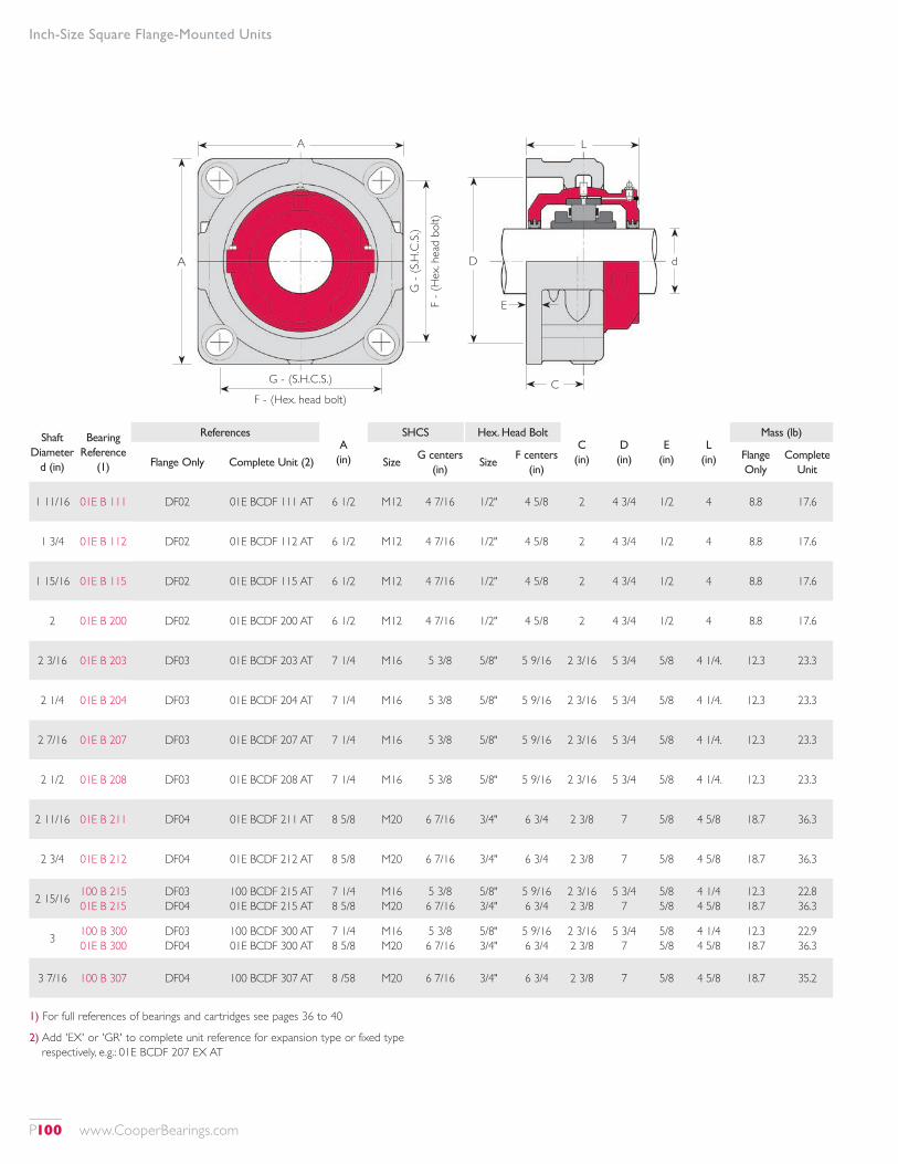
dDA
A
F - (Hex. head bolt)
G - (S.H.C.S.)
E
C
L
F - (
Hex
. hea
d bo
lt)
G -
(S.H
.C.S.
)
Inch-Size Square Flange-Mounted Units
Shaft Diameter
d (in)
Bearing Reference
(1)
ReferencesA
(in)
SHCS Hex. Head BoltC
(in)D (in)
E (in)
L (in)
Mass (lb)
Flange Only Complete Unit (2) SizeG centers
(in)Size
F centers (in)
Flange Only
Complete Unit
1 11/16 01E B 111 DF02 01E BCDF 111 AT 6 1/2 M12 4 7/16 1/2" 4 5/8 2 4 3/4 1/2 4 8.8 17.6
1 3/4 01E B 112 DF02 01E BCDF 112 AT 6 1/2 M12 4 7/16 1/2" 4 5/8 2 4 3/4 1/2 4 8.8 17.6
1 15/16 01E B 115 DF02 01E BCDF 115 AT 6 1/2 M12 4 7/16 1/2" 4 5/8 2 4 3/4 1/2 4 8.8 17.6
2 01E B 200 DF02 01E BCDF 200 AT 6 1/2 M12 4 7/16 1/2" 4 5/8 2 4 3/4 1/2 4 8.8 17.6
2 3/16 01E B 203 DF03 01E BCDF 203 AT 7 1/4 M16 5 3/8 5/8" 5 9/16 2 3/16 5 3/4 5/8 4 1/4. 12.3 23.3
2 1/4 01E B 204 DF03 01E BCDF 204 AT 7 1/4 M16 5 3/8 5/8" 5 9/16 2 3/16 5 3/4 5/8 4 1/4. 12.3 23.3
2 7/16 01E B 207 DF03 01E BCDF 207 AT 7 1/4 M16 5 3/8 5/8" 5 9/16 2 3/16 5 3/4 5/8 4 1/4. 12.3 23.3
2 1/2 01E B 208 DF03 01E BCDF 208 AT 7 1/4 M16 5 3/8 5/8" 5 9/16 2 3/16 5 3/4 5/8 4 1/4. 12.3 23.3
2 11/16 01E B 211 DF04 01E BCDF 211 AT 8 5/8 M20 6 7/16 3/4" 6 3/4 2 3/8 7 5/8 4 5/8 18.7 36.3
2 3/4 01E B 212 DF04 01E BCDF 212 AT 8 5/8 M20 6 7/16 3/4" 6 3/4 2 3/8 7 5/8 4 5/8 18.7 36.3
2 15/16 100 B 215 01E B 215
DF03 DF04
100 BCDF 215 AT 01E BCDF 215 AT
7 1/4 8 5/8
M16 M20
5 3/8 6 7/16
5/8" 3/4"
5 9/16 6 3/4
2 3/16 2 3/8
5 3/4 7
5/8 5/8
4 1/4 4 5/8
12.3 18.7
22.8 36.3
3 100 B 300 01E B 300
DF03 DF04
100 BCDF 300 AT 01E BCDF 300 AT
7 1/4 8 5/8
M16 M20
5 3/8 6 7/16
5/8" 3/4"
5 9/16 6 3/4
2 3/16 2 3/8
5 3/4 7
5/8 5/8
4 1/4 4 5/8
12.3 18.7
22.9 36.3
3 7/16 100 B 307 DF04 100 BCDF 307 AT 8 /58 M20 6 7/16 3/4" 6 3/4 2 3/8 7 5/8 4 5/8 18.7 35.2
1) For full references of bearings and cartridges see pages 36 to 40
2) Add 'EX' or 'GR' to complete unit reference for expansion type or fixed type respectively, e.g.: 01E BCDF 207 EX AT
P100 www.CooperBearings.com
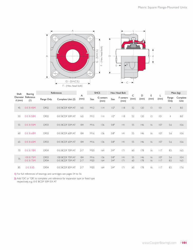
dDA
A
F - (Hex. head bolt)
G - (S.H.C.S.)
E
C
L
F - (
Hex
. hea
d bo
lt)
G -
(S.H
.C.S.
)
Metric Square Flange-Mounted Units
Shaft Diameter d (mm)
Bearing Reference
(1)
ReferencesA
(mm)
SHCS Hex. Head BoltC
(mm)D
(mm)E
(mm)L
(mm)
Mass (kg)
Flange Only Complete Unit (2) SizeG centers
(mm)Size
F centers (mm)
Flange Only
Complete Unit
45 01E B 45M DF02 01E BCDF 45M AT 165 M12 114 1/2" 118 52 120 13 101 4 8.0
50 01E B 50M DF02 01E BCDF 50M AT 165 M12 114 1/2" 118 52 120 13 101 4 8.0
55 01E B 55M DF03 01E BCDF 55M AT 184 M16 136 5/8" 141 55 146 16 107 5.6 10.6
60 01E B 60M DF03 01E BCDF 60M AT 184 M16 136 5/8" 141 55 146 16 107 5.6 10.6
65 01E B 65M DF03 01E BCDF 65M AT 184 M16 136 5/8" 141 55 146 16 107 5.6 10.6
70 01E B 70M DF04 01E BCDF 70M AT 217 M20 164 3/4" 171 60 178 16 117 8.5 16.5
75 100 B 75M 01E B 75M
DF03 DF04
100 BCDF 75M AT 01E BCDF 75M AT
184 217
M16 M20
136 164
5/8" 3/4"
141 171
55 60
146 178
16 16
107 117
5.6 8.5
10.4 16.5
85 01E B 85 DF04 01E BCDF 85M AT 217 M20 164 3/4" 171 60 178 16 117 8.5 17.6
1) For full references of bearings and cartridges see pages 54 to 56
2) Add 'EX' or 'GR' to complete unit reference for expansion type or fixed type respectively, e.g.: 01E BCDF 50M EX AT
www.CooperBearings.com P101
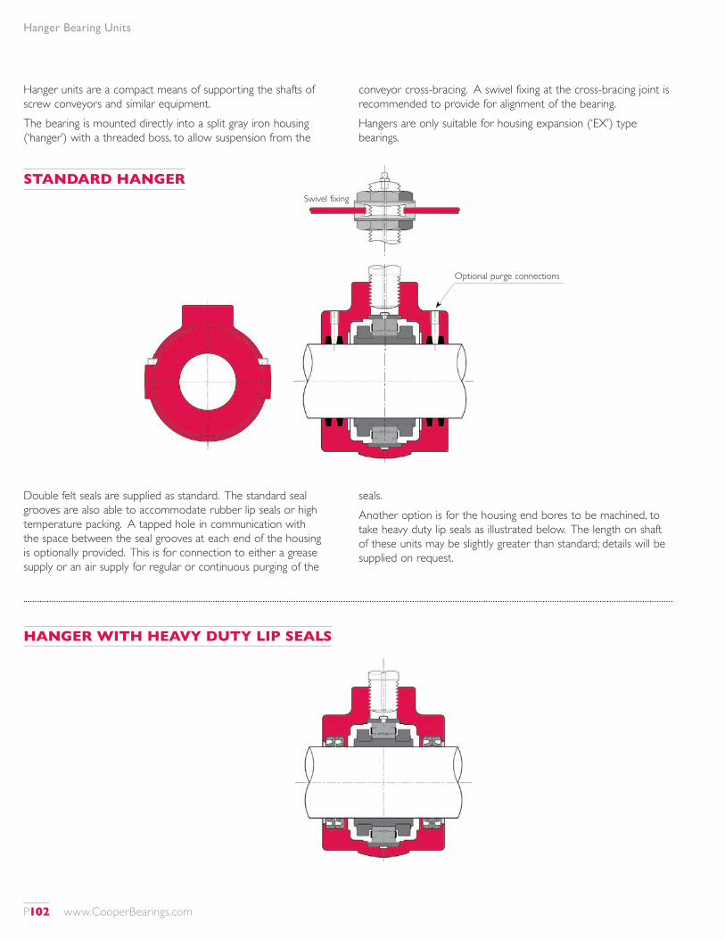
Hanger Bearing Units
Hanger units are a compact means of supporting the shafts of screw conveyors and similar equipment.The bearing is mounted directly into a split gray iron housing (‘hanger’) with a threaded boss, to allow suspension from the
conveyor cross-bracing. A swivel fixing at the cross-bracing joint is recommended to provide for alignment of the bearing.Hangers are only suitable for housing expansion (‘EX’) type bearings.
Double felt seals are supplied as standard. The standard seal grooves are also able to accommodate rubber lip seals or high temperature packing. A tapped hole in communication with the space between the seal grooves at each end of the housing is optionally provided. This is for connection to either a grease supply or an air supply for regular or continuous purging of the
seals.Another option is for the housing end bores to be machined, to take heavy duty lip seals as illustrated below. The length on shaft of these units may be slightly greater than standard; details will be supplied on request.
STANDARD HANGER
HANGER WITH HEAVY DUTY LIP SEALS
Optional purge connections
Swivel fixing
P102 www.CooperBearings.com
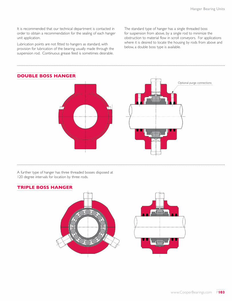
Hanger Bearing Units
It is recommended that our technical department is contacted in order to obtain a recommendation for the sealing of each hanger unit application.Lubrication points are not fitted to hangers as standard, with provision for lubrication of the bearing usually made through the suspension rod. Continuous grease feed is sometimes desirable.
The standard type of hanger has a single threaded boss for suspension from above, by a single rod to minimize the obstruction to material flow in scroll conveyors. For applications where it is desired to locate the housing by rods from above and below, a double boss type is available.
A further type of hanger has three threaded bosses disposed at 120 degree intervals for location by three rods.
DOUBLE BOSS HANGER
TRIPLE BOSS HANGER
Optional purge connections
www.CooperBearings.com P103
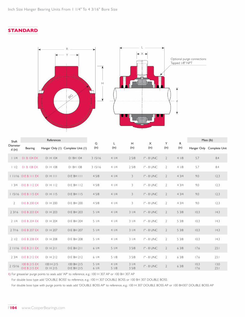
Inch Size Hanger Bearing Units From 1 1/4" To 4 3/16" Bore Size
Optional purge connections Tapped 1⁄8" NPT
R
ØG
Y
H
L
X
Shaft Diameter
d (in)
ReferencesG
(in)L
(in)H
(in)X
(in)Y
(in)R
(in)
Mass (lb)
Bearing Hanger Only (1) Complete Unit (1) Hanger Only Complete Unit
1 1/4 01 B 104 EX 01 H 104 01 BH 104 3 15/16 4 1/4 2 5/8 1" - 8 UNC 2 4 1/8 5.7 8.4
1 1/2 01 B 108 EX 01 H 108 01 BH 108 3 15/16 4 1/4 2 5/8 1" - 8 UNC 2 4 1/8 5.7 8.4
1 11/16 01E B 111 EX 01 H 111 01E BH 111 4 5/8 4 1/4 3 1" - 8 UNC 2 4 3/4 9.0 12.3
1 3/4 01E B 112 EX 01 H 112 01E BH 112 4 5/8 4 1/4 3 1" - 8 UNC 2 4 3/4 9.0 12.3
1 15/16 01E B 115 EX 01 H 115 01E BH 115 4 5/8 4 1/4 3 1" - 8 UNC 2 4 3/4 9.0 12.3
2 01E B 200 EX 01 H 200 01E BH 200 4 5/8 4 1/4 3 1" - 8 UNC 2 4 3/4 9.0 12.3
2 3/16 01E B 203 EX 01 H 203 01E BH 203 5 1/4 4 1/4 3 1/4 1" - 8 UNC 2 5 3/8 10.3 14.3
2 1/4 01E B 204 EX 01 H 204 01E BH 204 5 1/4 4 1/4 3 1/4 1" - 8 UNC 2 5 3/8 10.3 14.3
2 7/16 01E B 207 EX 01 H 207 01E BH 207 5 1/4 4 1/4 3 1/4 1" - 8 UNC 2 5 3/8 10.3 14.3
2 1/2 01E B 208 EX 01 H 208 01E BH 208 5 1/4 4 1/4 3 1/4 1" - 8 UNC 2 5 3/8 10.3 14.3
2 11/16 01E B 211 EX 01 H 211 01E BH 211 6 1/4 5 1/4 3 5/8 1" - 8 UNC 2 6 3/8 17.6 23.1
2 3/4 01E B 212 EX 01 H 212 01E BH 212 6 1/4 5 1/8 3 5/8 1" - 8 UNC 2 6 3/8 17.6 23.1
2 15/16 100 B 215 EX 01E B 215 EX
100 H 215 01 H 215
100 BH 215 01E BH 215
5 1/4 6 1/4
4 1/4 5 1/8
3 1/4 3 5/8 1" - 8 UNC 2 6 3/8 10.3
17.613.0 23.1
1) For grease/air purge points to seals add 'AP' to reference, e.g.: 100 H 307 AP or 100 BH 307 AP
For double boss type add 'DOUBLE BOSS' to reference, e.g.: 100 H 307 DOUBLE BOSS or 100 BH 307 DOUBLE BOSS
For double boss type with purge points to seals add 'DOUBLE BOSS AP' to reference, e.g.: 100 H 307 DOUBLE BOSS AP or 100 BH307 DOUBLE BOSS AP
STANDARD
d
P104 www.CooperBearings.com

Inch Size Hanger Bearing Units From 1 1/4" To 4 3/16" Bore Size
Shaft Diameter
d (in)
ReferencesG
(in)L
(in)H
(in)X
(in)Y
(in)R
(in)
Mass (lb)
Bearing Hanger Only (1) Complete Unit (1) Hanger Only Complete Unit
3 100 B 300 EX 01E B 300 EX
100 H 300 01 H 300
100 BH 300 01E BH 300
5 1/4 6 1/4
4 1/4 5 1/8
3 1/4 3 5/8
1" - 8 UNC 1" - 8 UNC
2 2 6 3/8 10.3
17.613.0 23.1
3 3/16 01E B 303 EX 01 H 303 01E BH 303 7 5 3/4 4 1/2 1 1/2" - 6 UNC 3 7 3/8 26.4 35.2
3 1/4 01E B 304 EX 01 H 304 01E BH 304 7 5 3/4 4 1/2 1 1/2" - 6 UNC 3 7 3/8 26.4 35.2
3 7/16 100 B 307 EX 01E B 307 EX
100 H 307 01 H 307
100 BH 307 01E BH 307
6 1/4 7
5 1/8 5 3/4
3 5/8 4 1/2
1" - 8 UNC 1 1/2" - 6 UNC
2 3 7 3/8 17.6
26.422.2 35.2
3 1/2 01E B 308 EX 01 H 308 01E BH 308 7 5 3/4 4 1/2 1 1/2" - 6 UNC 3 7 3/8 26.4 35.2
3 11/16 01E B 311 EX 01 H 311 01E BH 311 8 6 5 1 1/2" - 6 UNC 3 7 7/8 30.8 44.0
3 3/4 01E B 312 EX 01 H 312 01E BH 312 8 6 5 1 1/2" - 6 UNC 3 7 7/8 30.8 44.0
3 15/16 100 B 315 EX 01E B 315 EX
100 H 315 01 H 315
100 BH 315 01E BH 315
7 8
5 3/4 6
4 1/2 5
1 1/2" - 6 UNC 1 1/2" - 6 UNC
3 3 7 7/8 26.4
30.832.6 44.0
4 100 B 400 EX 01E B 400 EX
100 H 400 01 H 400
100 BH 400 01E BH 400
7 8
5 3/4 6
4 1/2 5
1 1/2" - 6 UNC 1 1/2" - 6 UNC
3 3 7 7/8 26.4
30.832.6 44.0
4 3/16 01E B 403 EX 01 H 403 01E BH 403 9 1/8 6 1/8 5 1/2 1 1/2" - 6 UNC 3 8 3/4 36.1 58.5
These shaft sizes are offered in single and double boss configuration. The single boss is the most common.
R
Y
H
H
L
X Optional purge connections Tapped 1⁄8" NPT
X
Y
ØGd
Single Boss Configuration Double Boss Configuration
STANDARD AND DOUBLE BOSS
www.CooperBearings.com P105
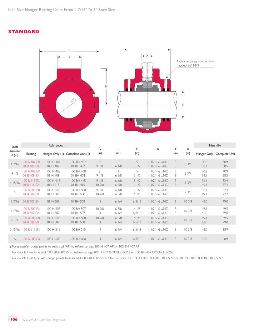
Inch Size Hanger Bearing Units From 4 7/16" To 6" Bore Size
Optional purge connections Tapped 1⁄8" NPT
R
ØG
Y
H
L
X
Shaft Diameter
d (in)
ReferencesG
(in)L
(in)H
(in)X Y
(in)R
(in)
Mass (lb)
Bearing Hanger Only (1) Complete Unit (1) Hanger Only Complete Unit
4 7/16 100 B 407 EX 01 B 407 EX
100 H 407 01 H 407
100 BH 407 01 BH 407
8 9 1/8
6 6 1/8
5 5 1/2
1 1/2" - 6 UNC 1 1/2" - 6 UNC
3 3 8 3/4 30.8
36.140.9 58.5
4 1/2 100 B 408 EX 01 B 408 EX
100 H 408 01 H 408
100 BH 408 01 BH 408
8 9 1/8
6 6 1/8
5 5 1/2
1 1/2" - 6 UNC 1 1/2" - 6 UNC
3 3 8 3/4 30.8
36.140.9 58.5
4 15/16 100 B 415 EX 01 B 415 EX
100 H 415 01 H 415
100 BH 415 01 BH 415
9 1/8 10 7/8
6 1/8 6 3/8
5 1/2 6 1/8
1 1/2" - 6 UNC 1 1/2" - 6 UNC
3 3 9 3/8 36.1
49.152.4 77.2
5 100 B 500 EX 01 B 500 EX
100 H 500 01 H 500
100 BH 500 01 BH 500
9 1/8 10 7/8
6 1/8 6 3/8
5 1/2 6 1/8
1 1/2" - 6 UNC 1 1/2" - 6 UNC
3 3 9 3/8 36.1
49.152.4 77.2
5 3/16 01 B 503 EX 01 H 503 01 BH 503 11 6 1/4 6 5/16 1 1/2" - 6 UNC 3 10 3/8 46.0 79.0
5 7/16 100 B 507 EX 01 B 507 EX
100 H 507 01 H 507
100 BH 507 01 BH 507
10 7/8 11
6 3/8 6 1/4
6 1/8 6 5/16
1 1/2" - 6 UNC 1 1/2" - 6 UNC
3 3 10 3/8 49.1
46.069.5 79.0
5 1/2 100 B 508 EX 01 B 508 EX
100 H 508 01 H 508
100 BH 508 01 BH 508
10 7/8 11
6 3/8 6 1/4
6 1/8 6 5/16
1 1/2" - 6 UNC 1 1/2" - 6 UNC
3 3 10 3/8 49.1
46.069.5 79.0
5 15/16 100 B 515 EX 100 H 515 100 BH 515 11 6 1/4 6 5/16 1 1/2" - 6 UNC 3 10 3/8 46.0 68.9
6 100 B 600 EX 100 H 600 100 BH 600 11 6 1/4 6 5/16 1 1/2" - 6 UNC 3 10 3/8 46.0 68.9
1) For grease/air purge points to seals add 'AP' to reference, e.g.: 100 H 407 AP or 100 BH 407 AP
For double boss type add 'DOUBLE BOSS' to reference, e.g.: 100 H 407 DOUBLE BOSS or 100 BH 407 DOUBLE BOSS
For double boss type with purge points to seals add 'DOUBLE BOSS AP' to reference, e.g.: 100 H 407 DOUBLE BOSS AP or 100 BH 407 DOUBLE BOSS AP
STANDARD
d
P106 www.CooperBearings.com
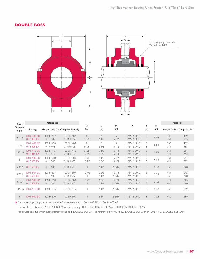
R
Y
Y
H
H
L
X Optional purge connections Tapped 1⁄8" NPT
X
Inch Size Hanger Bearing Units From 4 7/16" To 6" Bore Size
Shaft Diameter
d (in)
ReferencesG
(in)L
(in)H
(in)X Y
(in)R
(in)
Mass (lb)
Bearing Hanger Only (1) Complete Unit (1) Hanger Only Complete Unit
4 7/16 100 B 407 EX 01 B 407 EX
100 H 407 01 H 407
100 BH 407 01 BH 407
8 9 1/8
6 6 1/8
5 5 1/2
1 1/2" - 6 UNC 1 1/2" - 6 UNC
3 3 8 3/4 30.8
36.140.9 58.5
4 1/2 100 B 408 EX 01 B 408 EX
100 H 408 01 H 408
100 BH 408 01 BH 408
8 9 1/8
6 6 1/8
5 5 1/2
1 1/2" - 6 UNC 1 1/2" - 6 UNC
3 3 8 3/4 30.8
36.140.9 58.5
4 15/16 100 B 415 EX 01 B 415 EX
100 H 415 01 H 415
100 BH 415 01 BH 415
9 1/8 10 7/8
6 1/8 6 3/8
5 1/2 6 1/8
1 1/2" - 6 UNC 1 1/2" - 6 UNC
3 3 9 3/8 36.1
49.152.4 77.2
5 100 B 500 EX 01 B 500 EX
100 H 500 01 H 500
100 BH 500 01 BH 500
9 1/8 10 7/8
6 1/8 6 3/8
5 1/2 6 1/8
1 1/2" - 6 UNC 1 1/2" - 6 UNC
3 3 9 3/8 36.1
49.152.4 77.2
5 3/16 01 B 503 EX 01 H 503 01 BH 503 11 6 1/4 6 5/16 1 1/2" - 6 UNC 3 10 3/8 46.0 79.0
5 7/16 100 B 507 EX 01 B 507 EX
100 H 507 01 H 507
100 BH 507 01 BH 507
10 7/8 11
6 3/8 6 1/4
6 1/8 6 5/16
1 1/2" - 6 UNC 1 1/2" - 6 UNC
3 3 10 3/8 49.1
46.069.5 79.0
5 1/2 100 B 508 EX 01 B 508 EX
100 H 508 01 H 508
100 BH 508 01 BH 508
10 7/8 11
6 3/8 6 1/4
6 1/8 6 5/16
1 1/2" - 6 UNC 1 1/2" - 6 UNC
3 3 10 3/8 49.1
46.069.5 79.0
5 15/16 100 B 515 EX 100 H 515 100 BH 515 11 6 1/4 6 5/16 1 1/2" - 6 UNC 3 10 3/8 46.0 68.9
6 100 B 600 EX 100 H 600 100 BH 600 11 6 1/4 6 5/16 1 1/2" - 6 UNC 3 10 3/8 46.0 68.9
1) For grease/air purge points to seals add 'AP' to reference, e.g.: 100 H 407 AP or 100 BH 407 AP
For double boss type add 'DOUBLE BOSS' to reference, e.g.: 100 H 407 DOUBLE BOSS or 100 BH 407 DOUBLE BOSS
For double boss type with purge points to seals add 'DOUBLE BOSS AP' to reference, e.g.: 100 H 407 DOUBLE BOSS AP or 100 BH 407 DOUBLE BOSS AP
DOUBLE BOSS
d
www.CooperBearings.com P107
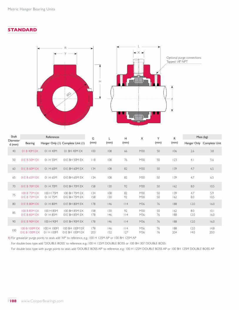
Metric Hanger Bearing Units
Optional purge connections Tapped 1⁄8" NPT
R
ØG
Y
H
L
X
Shaft Diameter d (mm)
References G (mm)
L (mm)
H (mm)
X Y (mm)
R (mm)
Mass (kg)
Bearing Hanger Only (1) Complete Unit (1) Hanger Only Complete Unit
40 01 B 40M EX 01 H 40M 01 BH 40M EX 100 108 66 M30 50 106 2.6 3.8
50 01E B 50M EX 01 H 50M 01E BH 50M EX 118 108 76 M30 50 123 4.1 5.6
60 01E B 60M EX 01 H 60M 01E BH 60M EX 134 108 82 M30 50 139 4.7 6.5
65 01E B 65M EX 01 H 65M 01E BH 65M EX 134 108 82 M30 50 139 4.7 6.5
70 01E B 70M EX 01 H 70M 01E BH 70M EX 158 130 92 M30 50 162 8.0 10.5
75 100 B 75M EX 01E B 75M EX
100 H 75M 01 H 75M
100 BH 75M EX 01E BH 75M EX
134 158
108 130
82 92
M30 M30
50 50
139 162
4.7 8.0
5.9 10.5
80 01E B 80M EX 01 H 80M 01E BH 80M EX 178 146 114 M36 76 188 12.0 16.0
85 100 B 85M EX 01E B 85M EX
100 H 85M 01 H 85M
100 BH 85M EX 01E BH 85M EX
158 178
130 146
92 114
M30 M36
50 76
162 188
8.0 12.0
10.1 16.0
90 01E B 90M EX 100 H 90M 01E BH 90M EX 178 146 114 M36 76 188 12.0 16.0
100 100 B 100M EX 01E B 100M EX
100 H 100M 01 H 100M
100 BH 100M EX 01E BH 100M EX
178 203
146 152
114 127
M36 M36
76 76
188 204
12.0 14.0
14.8 20.0
1) For grease/air purge points to seals add 'AP' to reference, e.g.: 100 H 125M AP or 100 BH 125M AP
For double boss type add 'DOUBLE BOSS' to reference, e.g.: 100 H 125M DOUBLE BOSS or 100 BH 307 DOUBLE BOSS
For double boss type with purge points to seals add 'DOUBLE BOSS AP' to reference, e.g.: 100 H 125M DOUBLE BOSS AP or 100 BH 125M DOUBLE BOSS AP
STANDARD
d
P108 www.CooperBearings.com
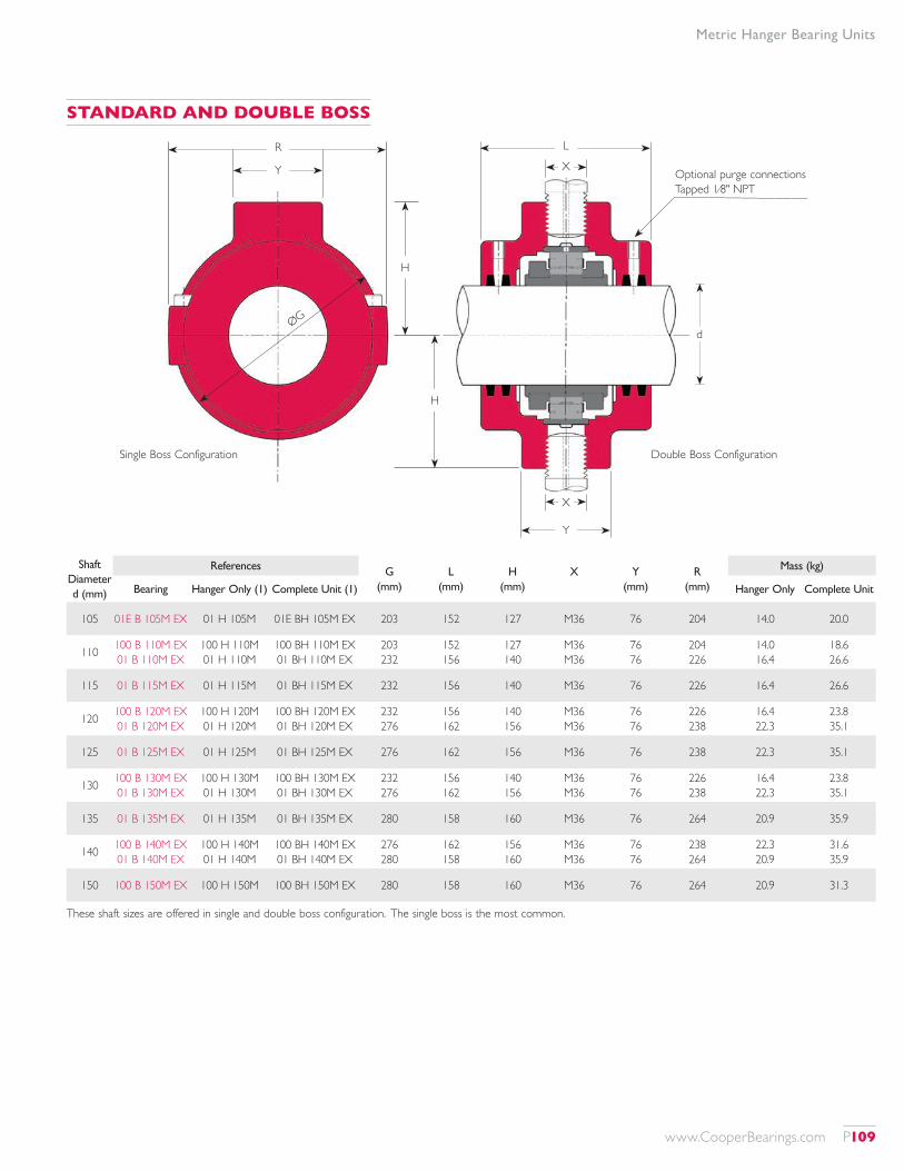
Metric Hanger Bearing Units
Shaft Diameter d (mm)
References G (mm)
L (mm)
H (mm)
X Y (mm)
R (mm)
Mass (kg)
Bearing Hanger Only (1) Complete Unit (1) Hanger Only Complete Unit
105 01E B 105M EX 01 H 105M 01E BH 105M EX 203 152 127 M36 76 204 14.0 20.0
110 100 B 110M EX 01 B 110M EX
100 H 110M 01 H 110M
100 BH 110M EX 01 BH 110M EX
203 232
152 156
127 140
M36 M36
76 76
204 226
14.0 16.4
18.6 26.6
115 01 B 115M EX 01 H 115M 01 BH 115M EX 232 156 140 M36 76 226 16.4 26.6
120 100 B 120M EX 01 B 120M EX
100 H 120M 01 H 120M
100 BH 120M EX 01 BH 120M EX
232 276
156 162
140 156
M36 M36
76 76
226 238
16.4 22.3
23.8 35.1
125 01 B 125M EX 01 H 125M 01 BH 125M EX 276 162 156 M36 76 238 22.3 35.1
130 100 B 130M EX 01 B 130M EX
100 H 130M 01 H 130M
100 BH 130M EX 01 BH 130M EX
232 276
156 162
140 156
M36 M36
76 76
226 238
16.4 22.3
23.8 35.1
135 01 B 135M EX 01 H 135M 01 BH 135M EX 280 158 160 M36 76 264 20.9 35.9
140 100 B 140M EX 01 B 140M EX
100 H 140M 01 H 140M
100 BH 140M EX 01 BH 140M EX
276 280
162 158
156 160
M36 M36
76 76
238 264
22.3 20.9
31.6 35.9
150 100 B 150M EX 100 H 150M 100 BH 150M EX 280 158 160 M36 76 264 20.9 31.3
R
Y
H
H
L
X Optional purge connections Tapped 1⁄8" NPT
X
Y
ØGd
Single Boss Configuration Double Boss Configuration
STANDARD AND DOUBLE BOSS
These shaft sizes are offered in single and double boss configuration. The single boss is the most common.
www.CooperBearings.com P109
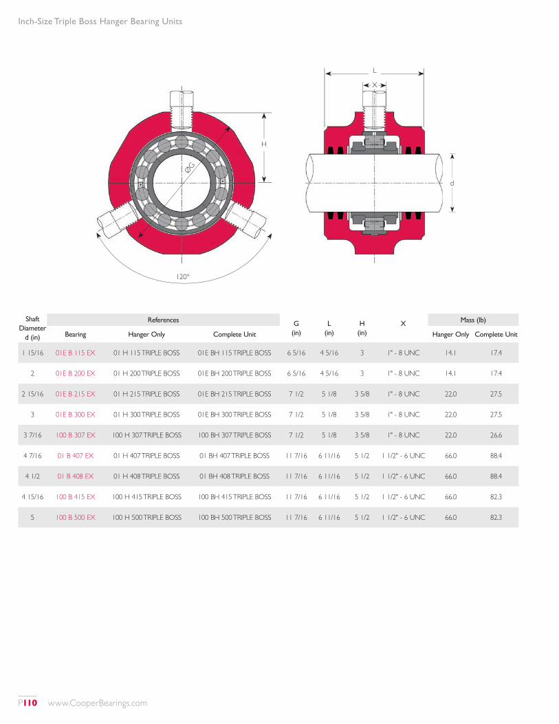
Inch-Size Triple Boss Hanger Bearing Units
Shaft Diameter
d (in)
References G (in)
L (in)
H (in)
X Mass (lb)
Bearing Hanger Only Complete Unit Hanger Only Complete Unit
1 15/16 01E B 115 EX 01 H 115 TRIPLE BOSS 01E BH 115 TRIPLE BOSS 6 5/16 4 5/16 3 1" - 8 UNC 14.1 17.4
2 01E B 200 EX 01 H 200 TRIPLE BOSS 01E BH 200 TRIPLE BOSS 6 5/16 4 5/16 3 1" - 8 UNC 14.1 17.4
2 15/16 01E B 215 EX 01 H 215 TRIPLE BOSS 01E BH 215 TRIPLE BOSS 7 1/2 5 1/8 3 5/8 1" - 8 UNC 22.0 27.5
3 01E B 300 EX 01 H 300 TRIPLE BOSS 01E BH 300 TRIPLE BOSS 7 1/2 5 1/8 3 5/8 1" - 8 UNC 22.0 27.5
3 7/16 100 B 307 EX 100 H 307 TRIPLE BOSS 100 BH 307 TRIPLE BOSS 7 1/2 5 1/8 3 5/8 1" - 8 UNC 22.0 26.6
4 7/16 01 B 407 EX 01 H 407 TRIPLE BOSS 01 BH 407 TRIPLE BOSS 11 7/16 6 11/16 5 1/2 1 1/2" - 6 UNC 66.0 88.4
4 1/2 01 B 408 EX 01 H 408 TRIPLE BOSS 01 BH 408 TRIPLE BOSS 11 7/16 6 11/16 5 1/2 1 1/2" - 6 UNC 66.0 88.4
4 15/16 100 B 415 EX 100 H 415 TRIPLE BOSS 100 BH 415 TRIPLE BOSS 11 7/16 6 11/16 5 1/2 1 1/2" - 6 UNC 66.0 82.3
5 100 B 500 EX 100 H 500 TRIPLE BOSS 100 BH 500 TRIPLE BOSS 11 7/16 6 11/16 5 1/2 1 1/2" - 6 UNC 66.0 82.3
L
X
H
120°
ØGd
P110 www.CooperBearings.com
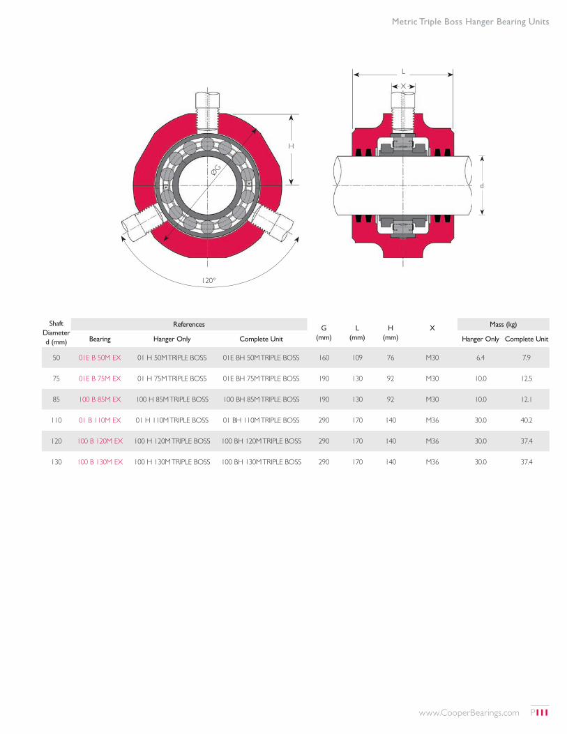
Metric Triple Boss Hanger Bearing Units
Shaft Diameter d (mm)
References G (mm)
L (mm)
H (mm)
X Mass (kg)
Bearing Hanger Only Complete Unit Hanger Only Complete Unit
50 01E B 50M EX 01 H 50M TRIPLE BOSS 01E BH 50M TRIPLE BOSS 160 109 76 M30 6.4 7.9
75 01E B 75M EX 01 H 75M TRIPLE BOSS 01E BH 75M TRIPLE BOSS 190 130 92 M30 10.0 12.5
85 100 B 85M EX 100 H 85M TRIPLE BOSS 100 BH 85M TRIPLE BOSS 190 130 92 M30 10.0 12.1
110 01 B 110M EX 01 H 110M TRIPLE BOSS 01 BH 110M TRIPLE BOSS 290 170 140 M36 30.0 40.2
120 100 B 120M EX 100 H 120M TRIPLE BOSS 100 BH 120M TRIPLE BOSS 290 170 140 M36 30.0 37.4
130 100 B 130M EX 100 H 130M TRIPLE BOSS 100 BH 130M TRIPLE BOSS 290 170 140 M36 30.0 37.4
L
X
H
120°
ØG
d
www.CooperBearings.com P111
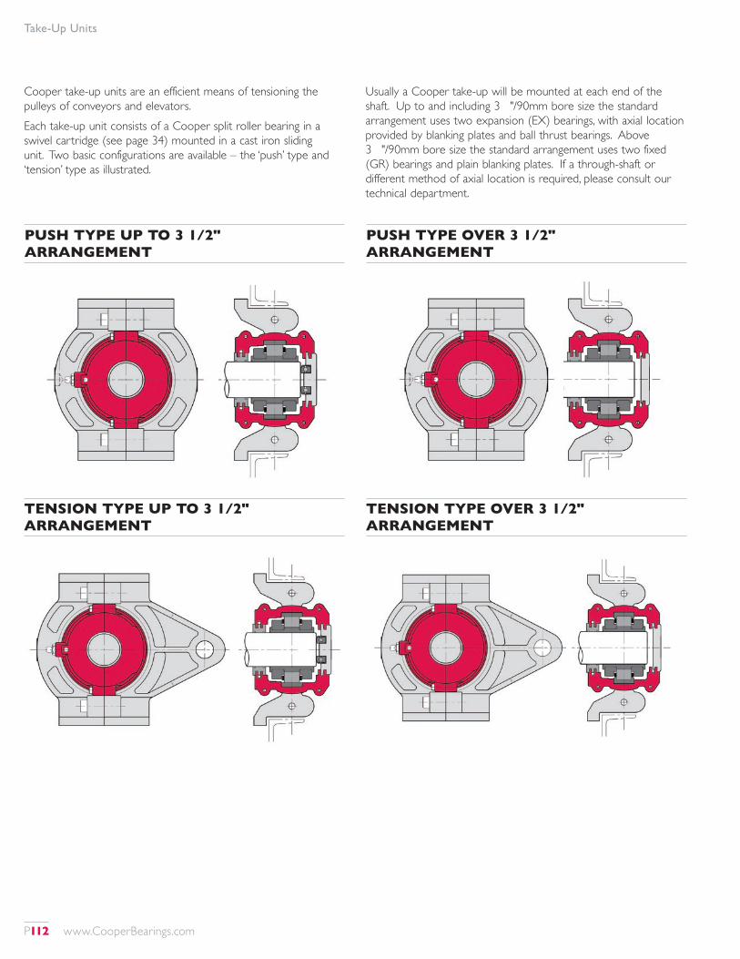
Take-Up Units
TENSION TYPE OVER 3 1/2" ARRANGEMENT
TENSION TYPE UP TO 3 1/2" ARRANGEMENT
PUSH TYPE OVER 3 1/2" ARRANGEMENT
PUSH TYPE UP TO 3 1/2" ARRANGEMENT
Cooper take-up units are an efficient means of tensioning the pulleys of conveyors and elevators.Each take-up unit consists of a Cooper split roller bearing in a swivel cartridge (see page 34) mounted in a cast iron sliding unit. Two basic configurations are available – the ‘push’ type and ‘tension’ type as illustrated.
Usually a Cooper take-up will be mounted at each end of the shaft. Up to and including 3½"/90mm bore size the standard arrangement uses two expansion (EX) bearings, with axial location provided by blanking plates and ball thrust bearings. Above 3½"/90mm bore size the standard arrangement uses two fixed (GR) bearings and plain blanking plates. If a through-shaft or different method of axial location is required, please consult our technical department.
P112 www.CooperBearings.com
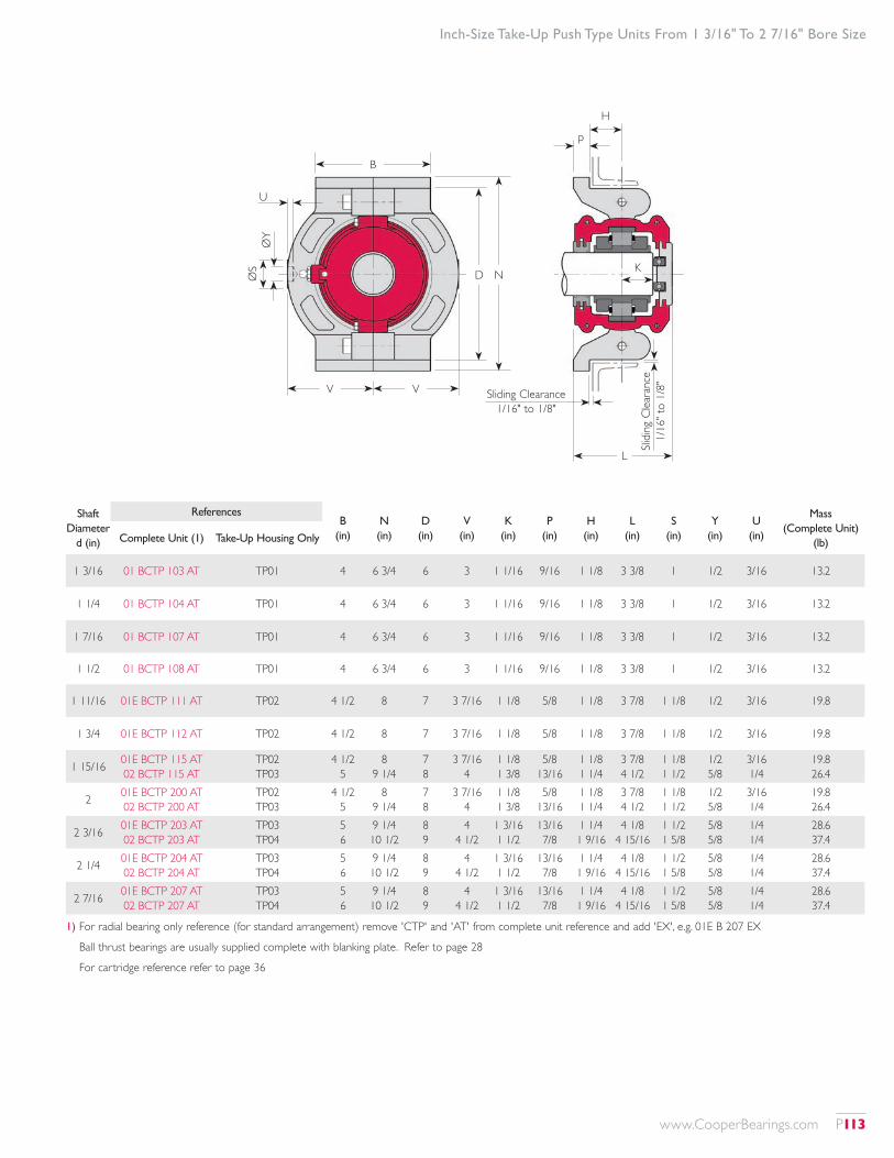
Inch-Size Take-Up Push Type Units From 1 3/16" To 2 7/16" Bore Size
Shaft Diameter
d (in)
ReferencesB
(in)N (in)
D (in)
V (in)
K (in)
P (in)
H (in)
L (in)
S (in)
Y (in)
U (in)
Mass (Complete Unit)
(lb)Complete Unit (1) Take-Up Housing Only
1 3/16 01 BCTP 103 AT TP01 4 6 3/4 6 3 1 1/16 9/16 1 1/8 3 3/8 1 1/2 3/16 13.2
1 1/4 01 BCTP 104 AT TP01 4 6 3/4 6 3 1 1/16 9/16 1 1/8 3 3/8 1 1/2 3/16 13.2
1 7/16 01 BCTP 107 AT TP01 4 6 3/4 6 3 1 1/16 9/16 1 1/8 3 3/8 1 1/2 3/16 13.2
1 1/2 01 BCTP 108 AT TP01 4 6 3/4 6 3 1 1/16 9/16 1 1/8 3 3/8 1 1/2 3/16 13.2
1 11/16 01E BCTP 111 AT TP02 4 1/2 8 7 3 7/16 1 1/8 5/8 1 1/8 3 7/8 1 1/8 1/2 3/16 19.8
1 3/4 01E BCTP 112 AT TP02 4 1/2 8 7 3 7/16 1 1/8 5/8 1 1/8 3 7/8 1 1/8 1/2 3/16 19.8
1 15/16 01E BCTP 115 AT 02 BCTP 115 AT
TP02 TP03
4 1/2 5
8 9 1/4
7 8
3 7/16 4
1 1/8 1 3/8
5/8 13/16
1 1/8 1 1/4
3 7/8 4 1/2
1 1/8 1 1/2
1/2 5/8
3/16 1/4
19.8 26.4
2 01E BCTP 200 AT 02 BCTP 200 AT
TP02 TP03
4 1/2 5
8 9 1/4
7 8
3 7/16 4
1 1/8 1 3/8
5/8 13/16
1 1/8 1 1/4
3 7/8 4 1/2
1 1/8 1 1/2
1/2 5/8
3/16 1/4
19.8 26.4
2 3/16 01E BCTP 203 AT 02 BCTP 203 AT
TP03 TP04
5 6
9 1/4 10 1/2
8 9
4 4 1/2
1 3/16 1 1/2
13/16 7/8
1 1/4 1 9/16
4 1/8 4 15/16
1 1/2 1 5/8
5/8 5/8
1/4 1/4
28.6 37.4
2 1/4 01E BCTP 204 AT 02 BCTP 204 AT
TP03 TP04
5 6
9 1/4 10 1/2
8 9
4 4 1/2
1 3/16 1 1/2
13/16 7/8
1 1/4 1 9/16
4 1/8 4 15/16
1 1/2 1 5/8
5/8 5/8
1/4 1/4
28.6 37.4
2 7/16 01E BCTP 207 AT 02 BCTP 207 AT
TP03 TP04
5 6
9 1/4 10 1/2
8 9
4 4 1/2
1 3/16 1 1/2
13/16 7/8
1 1/4 1 9/16
4 1/8 4 15/16
1 1/2 1 5/8
5/8 5/8
1/4 1/4
28.6 37.4
1) For radial bearing only reference (for standard arrangement) remove 'CTP' and 'AT' from complete unit reference and add 'EX', e.g. 01E B 207 EX
Ball thrust bearings are usually supplied complete with blanking plate. Refer to page 28
For cartridge reference refer to page 36
B
V V
K
U
Sliding Clearance 1/16" to 1/8"
Slidi
ng C
leara
nce
1/16
" to
1/8"
L
D NØS
ØY
H
p
www.CooperBearings.com P113
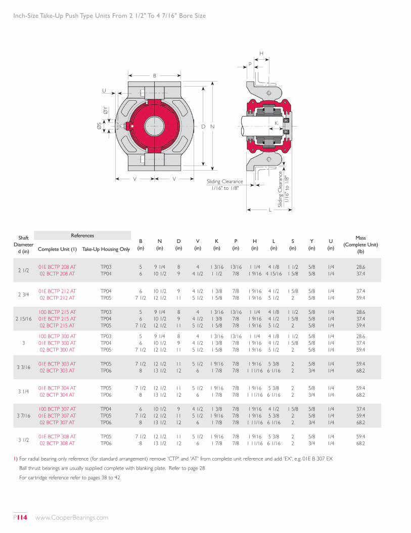
Inch-Size Take-Up Push Type Units From 2 1/2" To 4 7/16" Bore Size
Shaft Diameter
d (in)
ReferencesB
(in)N (in)
D (in)
V (in)
K (in)
P (in)
H (in)
L (in)
S (in)
Y (in)
U (in)
Mass (Complete Unit)
(lb)Complete Unit (1) Take-Up Housing Only
2 1/2 01E BCTP 208 AT 02 BCTP 208 AT
TP03 TP04
5 6
9 1/4 10 1/2
8 9
4 4 1/2
1 3/16 1 1/2
13/16 7/8
1 1/4 1 9/16
4 1/8 4 15/16
1 1/2 1 5/8
5/8 5/8
1/4 1/4
28.6 37.4
2 3/4 01E BCTP 212 AT 02 BCTP 212 AT
TP04 TP05
6 7 1/2
10 1/2 12 1/2
9 11
4 1/2 5 1/2
1 3/8 1 5/8
7/8 7/8
1 9/16 1 9/16
4 1/2 5 1/2
1 5/8 2
5/8 5/8
1/4 1/4
37.4 59.4
2 15/16100 BCTP 215 AT 01E BCTP 215 AT 02 BCTP 215 AT
TP03 TP04 TP05
5 6
7 1/2
9 1/4 10 1/2 12 1/2
8 9 11
4 4 1/2 5 1/2
1 3/16 1 3/8 1 5/8
13/16 7/8 7/8
1 1/4 1 9/16 1 9/16
4 1/8 4 1/2 5 1/2
1 1/2 1 5/8
2
5/8 5/8 5/8
1/4 1/4 1/4
28.6 37.4 59.4
3100 BCTP 300 AT 01E BCTP 300 AT 02 BCTP 300 AT
TP03 TP04 TP05
5 6
7 1/2
9 1/4 10 1/2 12 1/2
8 9 11
4 4 1/2 5 1/2
1 3/16 1 3/8 1 5/8
13/16 7/8 7/8
1 1/4 1 9/16 1 9/16
4 1/8 4 1/2 5 1/2
1 1/2 1 5/8
2
5/8 5/8 5/8
1/4 1/4 1/4
28.6 37.4 59.4
3 3/16 01E BCTP 303 AT 02 BCTP 303 AT
TP05 TP06
7 1/2 8
12 1/2 13 1/2
11 12
5 1/2 6
1 9/16 1 7/8
7/8 7/8
1 9/16 1 11/16
5 3/8 6 1/16
2 2
5/8 3/4
1/4 1/4
59.4 68.2
3 1/4 01E BCTP 304 AT 02 BCTP 304 AT
TP05 TP06
7 1/2 8
12 1/2 13 1/2
11 12
5 1/2 6
1 9/16 1 7/8
7/8 7/8
1 9/16 1 11/16
5 3/8 6 1/16
2 2
5/8 3/4
1/4 1/4
59.4 68.2
3 7/16100 BCTP 307 AT 01E BCTP 307 AT 02 BCTP 307 AT
TP04 TP05 TP06
6 7 1/2
8
10 1/2 12 1/2 13 1/2
9 11 12
4 1/2 5 1/2
6
1 3/8 1 9/16 1 7/8
7/8 7/8 7/8
1 9/16 1 9/16 1 11/16
4 1/2 5 3/8 6 1/16
1 5/8 2 2
5/8 5/8 3/4
1/4 1/4 1/4
37.4 59.4 68.2
3 1/2 01E BCTP 308 AT 02 BCTP 308 AT
TP05 TP06
7 1/2 8
12 1/2 13 1/2
11 12
5 1/2 6
1 9/16 1 7/8
7/8 7/8
1 9/16 1 11/16
5 3/8 6 1/16
2 2
5/8 3/4
1/4 1/4
59.4 68.2
1) For radial bearing only reference (for standard arrangement) remove 'CTP' and 'AT' from complete unit reference and add 'EX', e.g. 01E B 307 EX
Ball thrust bearings are usually supplied complete with blanking plate. Refer to page 28
For cartridge reference refer to pages 38 to 42
B
V V
K
U
Sliding Clearance 1/16" to 1/8"
Slidi
ng C
leara
nce
1/16
" to
1/8"
L
D NØS
ØY
H
p
P114 www.CooperBearings.com
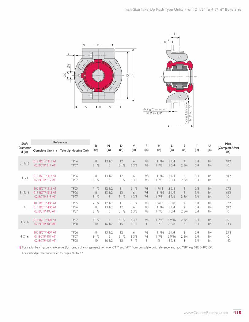
Inch-Size Take-Up Push Type Units From 2 1/2" To 4 7/16" Bore Size
Shaft Diameter
d (in)
ReferencesB
(in)N (in)
D (in)
V (in)
P (in)
H (in)
L (in)
S (in)
Y (in)
U (in)
Mass (Complete Unit)
(lb)Complete Unit (1) Take-Up Housing Only
3 11/16 01E BCTP 311 AT 02 BCTP 311 AT
TP06 TP07
8 8 1/2
13 1/2 15
12 13 1/2
6 6 3/8
7/8 7/8
1 11/16 1 7/8
5 1/4 5 3/4
2 2 3/4
3/4 3/4
1/4 1/4
68.2 101
3 3/4 01E BCTP 312 AT 02 BCTP 312 AT
TP06 TP07
8 8 1/2
13 1/2 15
12 13 1/2
6 6 3/8
7/8 7/8
1 11/16 1 7/8
5 1/4 5 3/4
2 2 3/4
3/4 3/4
1/4 1/4
68.2 101
3 15/16100 BCTP 315 AT 01E BCTP 315 AT 02 BCTP 315 AT
TP05 TP06 TP07
7 1/2 8
8 1/2
12 1/2 13 1/2
15
11 12
13 1/2
5 1/2 6
6 3/8
7/8 7/8 7/8
1 9/16 1 11/16 1 7/8
5 3/8 5 1/4 5 3/4
2 2
2 3/4
5/8 3/4 3/4
1/4 1/4 1/4
57.2 68.2 101
4100 BCTP 400 AT 01E BCTP 400 AT 02 BCTP 400 AT
TP05 TP06 TP07
7 1/2 8
8 1/2
12 1/2 13 1/2
15
11 12
13 1/2
5 1/2 6
6 3/8
7/8 7/8 7/8
1 9/16 1 11/16 1 7/8
5 3/8 5 1/4 5 3/4
2 2
2 3/4
5/8 3/4 3/4
1/4 1/4 1/4
57.2 68.2 101
4 3/16 01E BCTP 403 AT 02 BCTP 403 AT
TP07 TP08
8 1/2 10
15 16 1/2
13 1/2 15
6 3/8 7 1/2
7/8 1
1 7/8 2
5 9/16 6 3/8
2 3/4 3
3/4 3/4
1/4 1/4
101 143
4 7/16100 BCTP 407 AT 01 BCTP 407 AT 02 BCTP 407 AT
TP06 TP07 TP08
8 8 1/2 10
13 1/2 15
16 1/2
12 13 1/2
15
6 6 3/8 7 1/2
7/8 7/8 1
1 11/16 1 7/8
2
5 1/4 5 9/16 6 3/8
2 2 3/4
3
3/4 3/4 3/4
1/4 1/4 1/4
63.8 101 143
1) For radial bearing only reference (for standard arrangement) remove 'CTP' and 'AT' from complete unit reference and add 'GR', e.g. 01E B 400 GR
For cartridge reference refer to pages 40 to 42
B
V V
U
D NØS
ØY
L
H
p
Sliding Clearance 1/16" to 1/8"
Slidi
ng C
leara
nce
1/16
" to
1/8"
www.CooperBearings.com P115
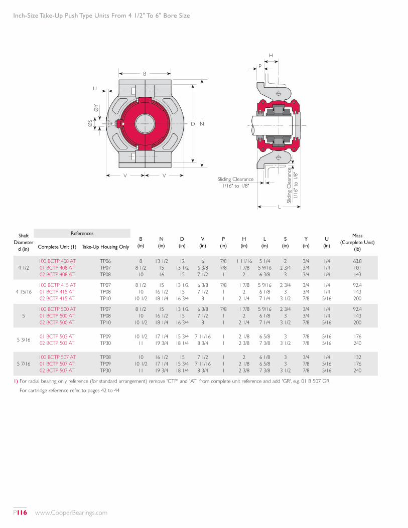
Inch-Size Take-Up Push Type Units From 4 1/2" To 6" Bore Size
Shaft Diameter
d (in)
ReferencesB
(in)N (in)
D (in)
V (in)
P (in)
H (in)
L (in)
S (in)
Y (in)
U (in)
Mass (Complete Unit)
(lb)Complete Unit (1) Take-Up Housing Only
4 1/2100 BCTP 408 AT 01 BCTP 408 AT 02 BCTP 408 AT
TP06 TP07 TP08
8 8 1/2 10
13 1/2 15 16
12 13 1/2
15
6 6 3/8 7 1/2
7/8 7/8 1
1 11/16 1 7/8
2
5 1/4 5 9/16 6 3/8
2 2 3/4
3
3/4 3/4 3/4
1/4 1/4 1/4
63.8 101 143
4 15/16100 BCTP 415 AT 01 BCTP 415 AT 02 BCTP 415 AT
TP07 TP08 TP10
8 1/2 10
10 1/2
15 16 1/2 18 1/4
13 1/2 15
16 3/4
6 3/8 7 1/2
8
7/8 1 1
1 7/8 2
2 1/4
5 9/16 6 1/8 7 1/4
2 3/4 3
3 1/2
3/4 3/4 7/8
1/4 1/4 5/16
92.4 143 200
5100 BCTP 500 AT 01 BCTP 500 AT 02 BCTP 500 AT
TP07 TP08 TP10
8 1/2 10
10 1/2
15 16 1/2 18 1/4
13 1/2 15
16 3/4
6 3/8 7 1/2
8
7/8 1 1
1 7/8 2
2 1/4
5 9/16 6 1/8 7 1/4
2 3/4 3
3 1/2
3/4 3/4 7/8
1/4 1/4 5/16
92.4 143 200
5 3/16 01 BCTP 503 AT 02 BCTP 503 AT
TP09 TP30
10 1/2 11
17 1/4 19 3/4
15 3/4 18 1/4
7 11/16 8 3/4
1 1
2 1/8 2 3/8
6 5/8 7 3/8
3 3 1/2
7/8 7/8
5/16 5/16
176 240
5 7/16100 BCTP 507 AT 01 BCTP 507 AT 02 BCTP 507 AT
TP08 TP09 TP30
10 10 1/2
11
16 1/2 17 1/4 19 3/4
15 15 3/4 18 1/4
7 1/2 7 11/16 8 3/4
1 1 1
2 2 1/8 2 3/8
6 1/8 6 5/8 7 3/8
3 3
3 1/2
3/4 7/8 7/8
1/4 5/16 5/16
132 176 240
1) For radial bearing only reference (for standard arrangement) remove 'CTP' and 'AT' from complete unit reference and add 'GR', e.g. 01 B 507 GR
For cartridge reference refer to pages 42 to 44
B
V V
U
D NØS
ØY
L
H
p
Sliding Clearance 1/16" to 1/8"
Slidi
ng C
leara
nce
1/16
" to
1/8"
P116 www.CooperBearings.com
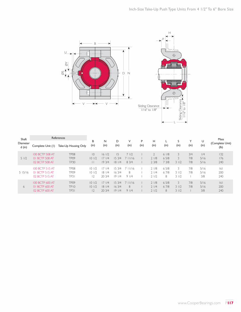
Inch-Size Take-Up Push Type Units From 4 1/2" To 6" Bore Size
Shaft Diameter
d (in)
ReferencesB
(in)N (in)
D (in)
V (in)
P (in)
H (in)
L (in)
S (in)
Y (in)
U (in)
Mass (Complete Unit)
(lb)Complete Unit (1) Take-Up Housing Only
5 1/2100 BCTP 508 AT 01 BCTP 508 AT 02 BCTP 508 AT
TP08 TP09 TP30
10 10 1/2
11
16 1/2 17 1/4 19 3/4
15 15 3/4 18 1/4
7 1/2 7 11/16 8 3/4
1 1 1
2 2 1/8 2 3/8
6 1/8 6 5/8 7 3/8
3 3
3 1/2
3/4 7/8 7/8
1/4 5/16 5/16
132 176 240
5 15/16100 BCTP 515 AT 01 BCTP 515 AT 02 BCTP 515 AT
TP08 TP09 TP31
10 1/2 10 1/2
12
17 1/4 18 1/4 20 3/4
15 3/4 16 3/4 19 1/4
7 11/16 8
9 1/4
1 1 1
2 1/8 2 1/4 2 1/2
6 5/8 6 7/8
8
3 3 1/2 3 1/2
7/8 7/8 1
5/16 5/16 3/8
161 200 240
6100 BCTP 600 AT 01 BCTP 600 AT 02 BCTP 600 AT
TP09 TP10 TP31
10 1/2 10 1/2
12
17 1/4 18 1/4 20 3/4
15 3/4 16 3/4 19 1/4
7 11/16 8
9 1/4
1 1 1
2 1/8 2 1/4 2 1/2
6 5/8 6 7/8
8
3 3 1/2 3 1/2
7/8 7/8 1
5/16 5/16 3/8
161 200 240
B
V V
U
D NØS
ØY
L
H
p
Sliding Clearance 1/16" to 1/8"
Slidi
ng C
leara
nce
1/16
" to
1/8"
www.CooperBearings.com P117
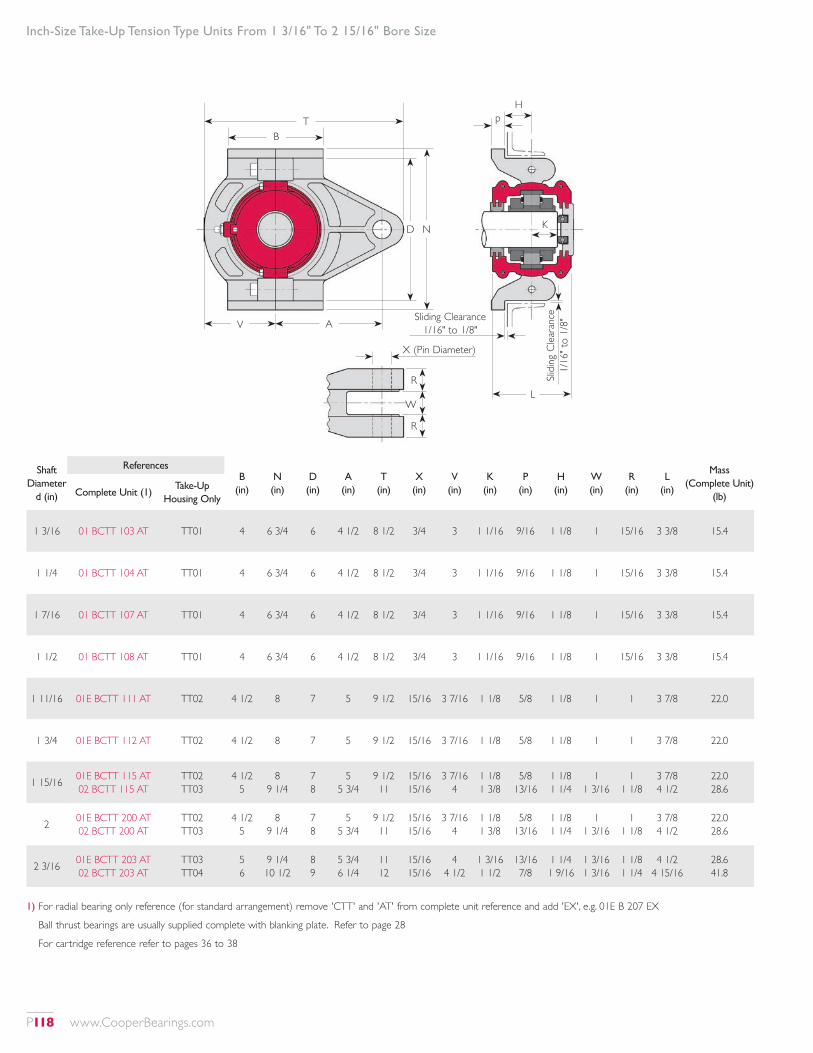
Inch-Size Take-Up Tension Type Units From 1 3/16" To 2 15/16" Bore Size
Shaft Diameter
d (in)
ReferencesB
(in)N (in)
D (in)
A (in)
T (in)
X (in)
V (in)
K (in)
P (in)
H (in)
W (in)
R (in)
L (in)
Mass (Complete Unit)
(lb)Complete Unit (1)Take-Up
Housing Only
1 3/16 01 BCTT 103 AT TT01 4 6 3/4 6 4 1/2 8 1/2 3/4 3 1 1/16 9/16 1 1/8 1 15/16 3 3/8 15.4
1 1/4 01 BCTT 104 AT TT01 4 6 3/4 6 4 1/2 8 1/2 3/4 3 1 1/16 9/16 1 1/8 1 15/16 3 3/8 15.4
1 7/16 01 BCTT 107 AT TT01 4 6 3/4 6 4 1/2 8 1/2 3/4 3 1 1/16 9/16 1 1/8 1 15/16 3 3/8 15.4
1 1/2 01 BCTT 108 AT TT01 4 6 3/4 6 4 1/2 8 1/2 3/4 3 1 1/16 9/16 1 1/8 1 15/16 3 3/8 15.4
1 11/16 01E BCTT 111 AT TT02 4 1/2 8 7 5 9 1/2 15/16 3 7/16 1 1/8 5/8 1 1/8 1 1 3 7/8 22.0
1 3/4 01E BCTT 112 AT TT02 4 1/2 8 7 5 9 1/2 15/16 3 7/16 1 1/8 5/8 1 1/8 1 1 3 7/8 22.0
1 15/16 01E BCTT 115 AT 02 BCTT 115 AT
TT02 TT03
4 1/2 5
8 9 1/4
7 8
5 5 3/4
9 1/2 11
15/16 15/16
3 7/16 4
1 1/8 1 3/8
5/8 13/16
1 1/8 1 1/4
1 1 3/16
1 1 1/8
3 7/8 4 1/2
22.0 28.6
2 01E BCTT 200 AT 02 BCTT 200 AT
TT02 TT03
4 1/2 5
8 9 1/4
7 8
5 5 3/4
9 1/2 11
15/16 15/16
3 7/16 4
1 1/8 1 3/8
5/8 13/16
1 1/8 1 1/4
1 1 3/16
1 1 1/8
3 7/8 4 1/2
22.0 28.6
2 3/16 01E BCTT 203 AT 02 BCTT 203 AT
TT03 TT04
5 6
9 1/4 10 1/2
8 9
5 3/4 6 1/4
11 12
15/16 15/16
4 4 1/2
1 3/16 1 1/2
13/16 7/8
1 1/4 1 9/16
1 3/16 1 3/16
1 1/8 1 1/4
4 1/2 4 15/16
28.6 41.8
1) For radial bearing only reference (for standard arrangement) remove 'CTT' and 'AT' from complete unit reference and add 'EX', e.g. 01E B 207 EX
Ball thrust bearings are usually supplied complete with blanking plate. Refer to page 28
For cartridge reference refer to pages 36 to 38
K
L
D N
Hp
R
W
R
X (Pin Diameter)
Slidi
ng C
leara
nce
1/16
" to
1/8"Sliding Clearance
1/16" to 1/8"
B
V A
T
P118 www.CooperBearings.com
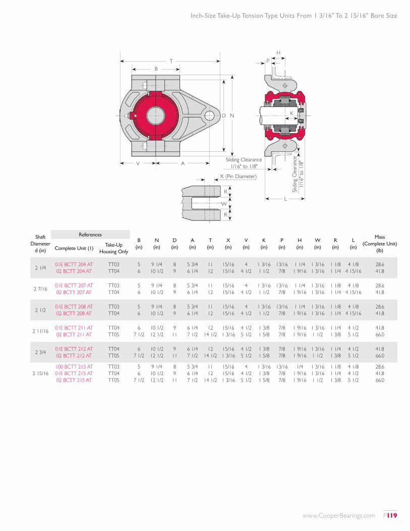
Inch-Size Take-Up Tension Type Units From 1 3/16" To 2 15/16" Bore Size
Shaft Diameter
d (in)
ReferencesB
(in)N (in)
D (in)
A (in)
T (in)
X (in)
V (in)
K (in)
P (in)
H (in)
W (in)
R (in)
L (in)
Mass (Complete Unit)
(lb)Complete Unit (1)Take-Up
Housing Only
2 1/4 01E BCTT 204 AT 02 BCTT 204 AT
TT03 TT04
5 6
9 1/4 10 1/2
8 9
5 3/4 6 1/4
11 12
15/16 15/16
4 4 1/2
1 3/16 1 1/2
13/16 7/8
1 1/4 1 9/16
1 3/16 1 3/16
1 1/8 1 1/4
4 1/8 4 15/16
28.6 41.8
2 7/16 01E BCTT 207 AT 02 BCTT 207 AT
TT03 TT04
5 6
9 1/4 10 1/2
8 9
5 3/4 6 1/4
11 12
15/16 15/16
4 4 1/2
1 3/16 1 1/2
13/16 7/8
1 1/4 1 9/16
1 3/16 1 3/16
1 1/8 1 1/4
4 1/8 4 15/16
28.6 41.8
2 1/2 01E BCTT 208 AT 02 BCTT 208 AT
TT03 TT04
5 6
9 1/4 10 1/2
8 9
5 3/4 6 1/4
11 12
15/16 15/16
4 4 1/2
1 3/16 1 1/2
13/16 7/8
1 1/4 1 9/16
1 3/16 1 3/16
1 1/8 1 1/4
4 1/8 4 15/16
28.6 41.8
2 11/16 01E BCTT 211 AT 02 BCTT 211 AT
TT04 TT05
6 7 1/2
10 1/2 12 1/2
9 11
6 1/4 7 1/2
12 14 1/2
15/16 1 3/16
4 1/2 5 1/2
1 3/8 1 5/8
7/8 7/8
1 9/16 1 9/16
1 3/16 1 1/2
1 1/4 1 3/8
4 1/2 5 1/2
41.8 66.0
2 3/4 01E BCTT 212 AT 02 BCTT 212 AT
TT04 TT05
6 7 1/2
10 1/2 12 1/2
9 11
6 1/4 7 1/2
12 14 1/2
15/16 1 3/16
4 1/2 5 1/2
1 3/8 1 5/8
7/8 7/8
1 9/16 1 9/16
1 3/16 1 1/2
1 1/4 1 3/8
4 1/2 5 1/2
41.8 66.0
2 15/16100 BCTT 215 AT 01E BCTT 215 AT 02 BCTT 215 AT
TT03 TT04 TT05
5 6
7 1/2
9 1/4 10 1/2 12 1/2
8 9 11
5 3/4 6 1/4 7 1/2
11 12
14 1/2
15/16 15/16 1 3/16
4 4 1/2 5 1/2
1 3/16 1 3/8 1 5/8
13/16 7/8 7/8
1/4 1 9/16 1 9/16
1 3/16 1 3/16 1 1/2
1 1/8 1 1/4 1 3/8
4 1/8 4 1/2 5 1/2
28.6 41.8 66.0
K
L
D N
Hp
R
W
R
X (Pin Diameter)
Slidi
ng C
leara
nce
1/16
" to
1/8"Sliding Clearance
1/16" to 1/8"
B
V A
T
www.CooperBearings.com P119
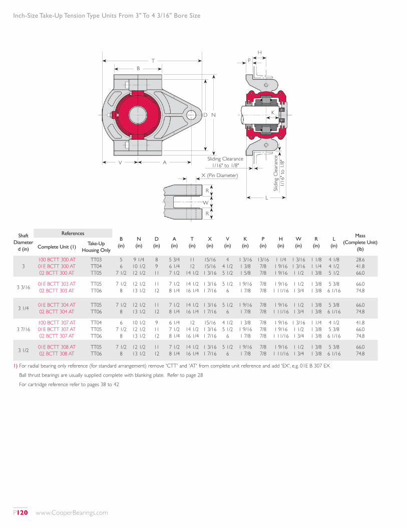
Inch-Size Take-Up Tension Type Units From 3" To 4 3/16" Bore Size
Shaft Diameter
d (in)
ReferencesB
(in)N (in)
D (in)
A (in)
T (in)
X (in)
V (in)
K (in)
P (in)
H (in)
W (in)
R (in)
L (in)
Mass (Complete Unit)
(lb)Complete Unit (1)Take-Up
Housing Only
3100 BCTT 300 AT 01E BCTT 300 AT 02 BCTT 300 AT
TT03 TT04 TT05
5 6
7 1/2
9 1/4 10 1/2 12 1/2
8 9 11
5 3/4 6 1/4 7 1/2
11 12
14 1/2
15/16 15/16 1 3/16
4 4 1/2 5 1/2
1 3/16 1 3/8 1 5/8
13/16 7/8 7/8
1 1/4 1 9/16 1 9/16
1 3/16 1 3/16 1 1/2
1 1/8 1 1/4 1 3/8
4 1/8 4 1/2 5 1/2
28.6 41.8 66.0
3 3/16 01E BCTT 303 AT 02 BCTT 303 AT
TT05 TT06
7 1/2 8
12 1/2 13 1/2
11 12
7 1/2 8 1/4
14 1/2 16 1/4
1 3/16 1 7/16
5 1/2 6
1 9/16 1 7/8
7/8 7/8
1 9/16 1 11/16
1 1/2 1 3/4
1 3/8 1 3/8
5 3/8 6 1/16
66.0 74.8
3 1/4 01E BCTT 304 AT 02 BCTT 304 AT
TT05 TT06
7 1/2 8
12 1/2 13 1/2
11 12
7 1/2 8 1/4
14 1/2 16 1/4
1 3/16 1 7/16
5 1/2 6
1 9/16 1 7/8
7/8 7/8
1 9/16 1 11/16
1 1/2 1 3/4
1 3/8 1 3/8
5 3/8 6 1/16
66.0 74.8
3 7/16100 BCTT 307 AT 01E BCTT 307 AT 02 BCTT 307 AT
TT04 TT05 TT06
6 7 1/2
8
10 1/2 12 1/2 13 1/2
9 11 12
6 1/4 7 1/2 8 1/4
12 14 1/2 16 1/4
15/16 1 3/16 1 7/16
4 1/2 5 1/2
6
1 3/8 1 9/16 1 7/8
7/8 7/8 7/8
1 9/16 1 9/16 1 11/16
1 3/16 1 1/2 1 3/4
1 1/4 1 3/8 1 3/8
4 1/2 5 3/8 6 1/16
41.8 66.0 74.8
3 1/2 01E BCTT 308 AT 02 BCTT 308 AT
TT05 TT06
7 1/2 8
12 1/2 13 1/2
11 12
7 1/2 8 1/4
14 1/2 16 1/4
1 3/16 1 7/16
5 1/2 6
1 9/16 1 7/8
7/8 7/8
1 9/16 1 11/16
1 1/2 1 3/4
1 3/8 1 3/8
5 3/8 6 1/16
66.0 74.8
1) For radial bearing only reference (for standard arrangement) remove 'CTT' and 'AT' from complete unit reference and add 'EX', e.g. 01E B 307 EX
Ball thrust bearings are usually supplied complete with blanking plate. Refer to page 28
For cartridge reference refer to pages 38 to 42
K
L
D N
Hp
R
W
R
X (Pin Diameter)
Slidi
ng C
leara
nce
1/16
" to
1/8"Sliding Clearance
1/16" to 1/8"
B
V A
T
P120 www.CooperBearings.com
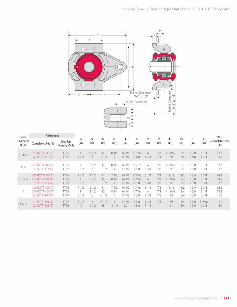
Inch-Size Take-Up Tension Type Units From 3" To 4 3/16" Bore Size
Shaft Diameter
d (in)
ReferencesB
(in)N (in)
D (in)
A (in)
T (in)
X (in)
V (in)
P (in)
H (in)
W (in)
R (in)
L (in)
Mass (Complete Unit)
(lb)Complete Unit (1)Take-Up
Housing Only
3 11/16 01E BCTT 311 AT 02 BCTT 311 AT
TT06 TT07
8 8 1/2
13 1/2 15
12 13 1/2
8 1/4 9
16 1/4 17 1/2
1 7/16 1 5/8
6 6 3/8
7/8 7/8
1 11/16 1 7/8
1 3/4 1 3/4
1 3/8 1 5/8
5 1/4 5 3/4
74.8 112
3 3/4 01E BCTT 312 AT 02 BCTT 312 AT
TT06 TT07
8 8 1/2
13 1/2 15
12 13 1/2
8 1/4 9
16 1/4 17 1/2
11 7/16 1 5/8
6 6 3/8
7/8 7/8
1 11/16 1 7/8
1 3/4 1 3/4
1 3/8 1 5/8
5 1/4 5 3/4
74.8 112
3 15/16100 BCTT 315 AT 01E BCTT 315 AT 02 BCTT 315 AT
TT05 TT06 TT07
7 1/2 8
8 1/2
12 1/2 13 1/2
15
11 12
13 1/2
7 1/2 8 1/4
9
14 1/2 16 1/4 17 1/2
1 3/16 1 7/16 1 5/8
5 1/2 6
6 3/8
7/8 7/8 7/8
1 9/16 1 11/16 1 7/8
1 1/2 1 3/4 1 3/4
1 3/4 1 3/8 1 5/8
5 3/8 5 1/4 5 3/4
63.8 74.8 112
4100 BCTT 400 AT 01E BCTT 400 AT 02 BCTT 400 AT
TT05 TT06 TT07
7 1/2 8
8 1/2
12 1/2 13 1/2
15
11 12
13 1/2
7 1/2 8 1/4
9
14 1/2 16 1/4 17 1/2
1 3/16 1 7/16 1 5/8
5 1/2 6
6 3/8
7/8 7/8 7/8
1 9/16 1 11/16 1 7/8
1 1/2 1 3/4 1 3/4
1 3/4 1 3/8 1 5/8
5 3/8 5 1/4 5 3/4
63.8 74.8 112
4 3/16 01 BCTT 403 AT 02 BCTT 403 AT
TT07 TT08
8 1/2 10
15 16 1/2
13 1/2 15
9 10 1/4
17 1/2 20
1 5/8 1 5/8
6 3/8 7 1/2
7/8 1
1 7/8 2
1 3/4 1 3/4
1 5/8 1 3/4
5 9/16 6 3/8
112 156
L
Hp
Slidi
ng C
leara
nce
1/16
" to
1/8"
D N
R
W
R
X (Pin Diameter)
Sliding Clearance 1/16" to 1/8"
B
V A
T
www.CooperBearings.com P121
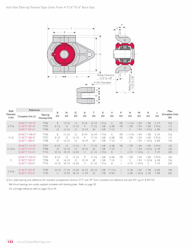
Inch-Size Take-Up Tension Type Units From 4 7/16" To 6" Bore Size
Shaft Diameter
d (in)
ReferencesB
(in)N (in)
D (in)
A (in)
T (in)
X (in)
V (in)
P (in)
H (in)
W (in)
R (in)
L (in)
Mass (Complete Unit)
(lb)Complete Unit (1)Take-Up
Housing Only
4 7/16100 BCTT 407 AT 01 BCTT 407 AT 02 BCTT 407 AT
TT06 TT07 TT08
8 8 1/2 10
13 1/2 15
16 1/2
12 13 1/2
15
8 1/4 9
10 1/4
16 1/4 17 1/2
20
1 7/16 1 5/8 1 5/8
6 6 3/8 7 1/2
7/8 7/8 1
1 11/16 1 7/8
2
1 3/4 1 3/4 1 3/4
1 3/8 1 5/8
1 15/16
5 1/4 5 9/16 6 3/8
72.6 112 156
4 1/2100 BCTT 408 AT 01 BCTT 408 AT 02 BCTT 408 AT
TT06 TT07 TT08
8 8 1/2 10
13 1/2 15
16 1/2
12 13 1/2
15
8 1/4 9
10 1/4
16 1/4 17 1/2
20
1 7/16 1 5/8 1 5/8
6 6 3/8 7 1/2
7/8 7/8 1
1 11/16 1 7/8
2
1 3/4 1 3/4 1 3/4
1 3/8 1 5/8
1 15/16
5 1/4 5 9/16 6 3/8
72.6 112 156
4 15/16100 BCTT 415 AT 01 BCTT 415 AT 02 BCTT 415 AT
TT07 TT08 TT10
8 1/2 10
10 1/2
15 16 1/2 18 1/4
13 1/2 15
16 3/4
9 10 1/4
11
17 1/2 20
21 1/2
1 5/8 1 5/8 1 7/16
6 3/8 7 1/2
8
7/8 1 1
1 7/8 2
2 1/4
1 3/4 1 3/4
1 15/16
1 5/8 1 15/16
2
5 9/16 6 1/8 7 1/4
103 156 220
5100 BCTT 500 AT 01 BCTT 500 AT 02 BCTT 500 AT
TT07 TT08 TT10
8 1/2 10
10 1/2
15 16 1/2 18 1/4
13 1/2 15
16 3/4
9 10 1/4
11
17 1/2 20
21 1/2
1 5/8 1 5/8 1 7/16
6 3/8 7 1/2
8
7/8 1 1
1 7/8 2
2 1/4
1 3/4 1 3/4
1 15/16
1 5/8 1 15/16
2
5 9/16 6 1/8 7 1/4
103 156 220
5 3/16 01 BCTT 503 AT 02 BCTT 503 AT
TT09 TT30
10 1/2 11
17 1/4 19 3/4
15 3/4 18 1/4
10 1/2 11 3/4
20 1/4 23
1 5/8 1 7/8
7 11/16 8 3/4
1 1
2 1/8 2 3/8
1 3/4 1 15/16
1 7/8 2 1/8
6 5/8 7 3/8
196 262
1) For radial bearing only reference (for standard arrangement) remove 'CTT' and 'AT' from complete unit reference and add 'EX', e.g. 01 B 407 EX
Ball thrust bearings are usually supplied complete with blanking plate. Refer to page 28
For cartridge reference refer to pages 42 to 44
L
Hp
Slidi
ng C
leara
nce
1/16
" to
1/8"
D N
R
W
R
X (Pin Diameter)
Sliding Clearance 1/16" to 1/8"
B
V A
T
P122 www.CooperBearings.com
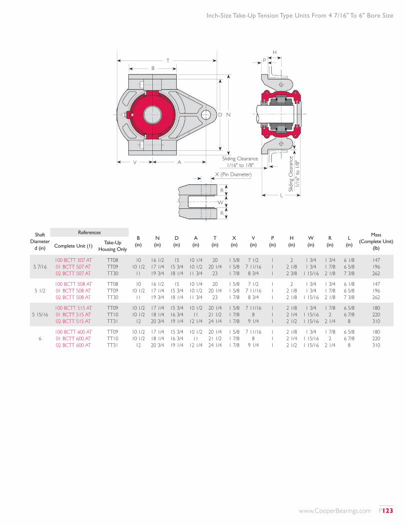
Inch-Size Take-Up Tension Type Units From 4 7/16" To 6" Bore Size
Shaft Diameter
d (in)
ReferencesB
(in)N (in)
D (in)
A (in)
T (in)
X (in)
V (in)
P (in)
H (in)
W (in)
R (in)
L (in)
Mass (Complete Unit)
(lb)Complete Unit (1)Take-Up
Housing Only
5 7/16100 BCTT 507 AT 01 BCTT 507 AT 02 BCTT 507 AT
TT08 TT09 TT30
10 10 1/2
11
16 1/2 17 1/4 19 3/4
15 15 3/4 18 1/4
10 1/4 10 1/2 11 3/4
20 20 1/4
23
1 5/8 1 5/8 1 7/8
7 1/2 7 11/16 8 3/4
1 1 1
2 2 1/8 2 3/8
1 3/4 1 3/4
1 15/16
1 3/4 1 7/8 2 1/8
6 1/8 6 5/8 7 3/8
147 196 262
5 1/2100 BCTT 508 AT 01 BCTT 508 AT 02 BCTT 508 AT
TT08 TT09 TT30
10 10 1/2
11
16 1/2 17 1/4 19 3/4
15 15 3/4 18 1/4
10 1/4 10 1/2 11 3/4
20 20 1/4
23
1 5/8 1 5/8 1 7/8
7 1/2 7 11/16 8 3/4
1 1 1
2 2 1/8 2 1/8
1 3/4 1 3/4
1 15/16
1 3/4 1 7/8 2 1/8
6 1/8 6 5/8 7 3/8
147 196 262
5 15/16100 BCTT 515 AT 01 BCTT 515 AT 02 BCTT 515 AT
TT09 TT10 TT31
10 1/2 10 1/2
12
17 1/4 18 1/4 20 3/4
15 3/4 16 3/4 19 1/4
10 1/2 11
12 1/4
20 1/4 21 1/2 24 1/4
1 5/8 1 7/8 1 7/8
7 11/16 8
9 1/4
1 1 1
2 1/8 2 1/4 2 1/2
1 3/4 1 15/16 1 15/16
1 7/8 2
2 1/4
6 5/8 6 7/8
8
180 220 310
6100 BCTT 600 AT 01 BCTT 600 AT 02 BCTT 600 AT
TT09 TT10 TT31
10 1/2 10 1/2
12
17 1/4 18 1/4 20 3/4
15 3/4 16 3/4 19 1/4
10 1/2 11
12 1/4
20 1/4 21 1/2 24 1/4
1 5/8 1 7/8 1 7/8
7 11/16 8
9 1/4
1 1 1
2 1/8 2 1/4 2 1/2
1 3/4 1 15/16 1 15/16
1 7/8 2
2 1/4
6 5/8 6 7/8
8
180 220 310
L
Hp
Slidi
ng C
leara
nce
1/16
" to
1/8"
D N
R
W
R
X (Pin Diameter)
Sliding Clearance 1/16" to 1/8"
B
V A
T
www.CooperBearings.com P123
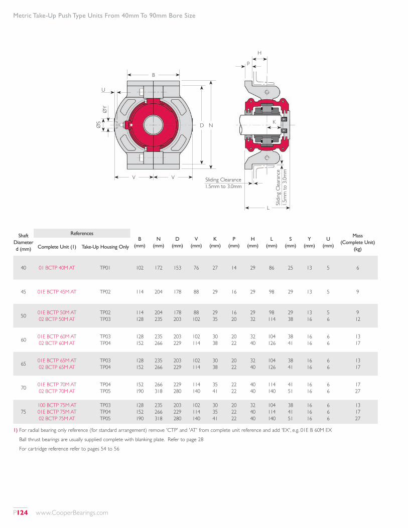
Shaft Diameter d (mm)
ReferencesB
(mm)N
(mm)D
(mm)V
(mm)K
(mm)P
(mm)H
(mm)L
(mm)S
(mm)Y
(mm)U
(mm)
Mass (Complete Unit)
(kg)Complete Unit (1) Take-Up Housing Only
40 01 BCTP 40M AT TP01 102 172 153 76 27 14 29 86 25 13 5 6
45 01E BCTP 45M AT TP02 114 204 178 88 29 16 29 98 29 13 5 9
50 01E BCTP 50M AT 02 BCTP 50M AT
TP02 TP03
114 128
204 235
178 203
88 102
29 35
16 20
29 32
98 114
29 38
13 16
5 6
9 12
60 01E BCTP 60M AT 02 BCTP 60M AT
TP03 TP04
128 152
235 266
203 229
102 114
30 38
20 22
32 40
104 126
38 41
16 16
6 6
13 17
65 01E BCTP 65M AT 02 BCTP 65M AT
TP03 TP04
128 152
235 266
203 229
102 114
30 38
20 22
32 40
104 126
38 41
16 16
6 6
13 17
70 01E BCTP 70M AT 02 BCTP 70M AT
TP04 TP05
152 190
266 318
229 280
114 140
35 41
22 22
40 40
114 140
41 51
16 16
6 6
17 27
75100 BCTP 75M AT 01E BCTP 75M AT 02 BCTP 75M AT
TP03 TP04 TP05
128 152 190
235 266 318
203 229 280
102 114 140
30 35 41
20 22 22
32 40 40
104 114 140
38 41 51
16 16 16
6 6 6
13 17 27
1) For radial bearing only reference (for standard arrangement) remove 'CTP' and 'AT' from complete unit reference and add 'EX', e.g. 01E B 60M EX
Ball thrust bearings are usually supplied complete with blanking plate. Refer to page 28
For cartridge reference refer to pages 54 to 56
Metric Take-Up Push Type Units From 40mm To 90mm Bore Size
B
V V
K
U
Sliding Clearance 1.5mm to 3.0mm
Slidi
ng C
leara
nce
1.5m
m to
3.0m
m
L
D NØS
ØY
H
p
P124 www.CooperBearings.com
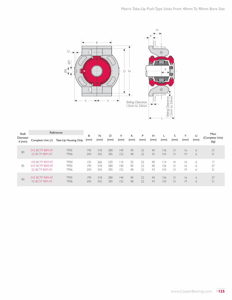
Metric Take-Up Push Type Units From 40mm To 90mm Bore Size
B
V V
K
U
Sliding Clearance 1.5mm to 3.0mm
Slidi
ng C
leara
nce
1.5m
m to
3.0m
m
L
D NØS
ØY
H
p
Shaft Diameter d (mm)
ReferencesB
(mm)N
(mm)D
(mm)V
(mm)K
(mm)P
(mm)H
(mm)L
(mm)S
(mm)Y
(mm)U
(mm)
Mass (Complete Unit)
(kg)Complete Unit (1) Take-Up Housing Only
80 01E BCTP 80M AT 02 BCTP 80M AT
TP05 TP06
190 204
318 342
280 305
140 152
40 48
22 22
40 43
136 154
51 51
16 19
6 6
27 31
85100 BCTP 85M AT 01E BCTP 85M AT 02 BCTP 85M AT
TP04 TP05 TP06
152 190 204
266 318 342
229 280 305
114 140 152
35 40 48
22 22 22
40 40 43
114 136 154
41 51 51
16 16 19
6 6 6
17 27 31
90 01E BCTP 90M AT 02 BCTP 90M AT
TP05 TP06
190 204
318 342
280 305
140 152
40 48
22 22
40 43
136 154
51 51
16 19
6 6
27 31
www.CooperBearings.com P125
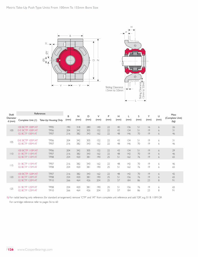
Metric Take-Up Push Type Units From 100mm To 155mm Bore Size
Shaft Diameter d (mm)
ReferencesB
(mm)N
(mm)D
(mm)V
(mm)P
(mm)H
(mm)L
(mm)S
(mm)Y
(mm)U
(mm)
Mass (Complete Unit)
(kg)Complete Unit (1) Take-Up Housing Only
100100 BCTP 100M AT 01E BCTP 100M AT 02 BCTP 100M AT
TP05 TP06 TP07
190 204 216
318 342 382
280 305 343
140 152 162
22 22 22
40 43 48
136 134 146
51 51 70
16 19 19
6 6 6
26 31 46
105 01E BCTP 105M AT 02 BCTP 105M AT
TP06 TP07
204 216
342 382
305 343
152 162
22 22
43 48
134 146
51 70
19 19
6 6
31 46
110100 BCTP 110M AT 01 BCTP 110M AT 02 BCTP 110M AT
TP06 TP07 TP08
204 216 254
342 382 420
305 343 381
152 162 190
22 22 25
43 48 51
134 142 162
51 70 76
19 19 19
6 6 6
29 46 65
115 01 BCTP 115M AT 02 BCTP 115M AT
TP07 TP08
216 254
382 420
343 381
162 190
22 25
48 51
142 162
70 76
19 19
6 6
46 65
120100 BCTP 120M AT 01 BCTP 120M AT 02 BCTP 120M AT
TP07 TP08 TP10
216 254 266
382 420 464
343 381 426
162 190 204
22 25 25
48 51 57
142 156 184
70 76 86
19 19 23
6 6 8
42 65 91
125 01 BCTP 125M AT 02 BCTP 125M AT
TP08 TP10
254 266
420 464
381 426
190 204
25 25
51 57
156 184
76 86
19 23
6 8
65 91
1) For radial bearing only reference (for standard arrangement) remove 'CTP' and 'AT' from complete unit reference and add 'GR', e.g. 01 B 110M GR
For cartridge reference refer to pages 56 to 60
B
V V
U
D NØS
ØY
L
H
p
Sliding Clearance 1.5mm to 3.0mm
Slidi
ng C
leara
nce
1.5m
m to
3.0m
m
P126 www.CooperBearings.com
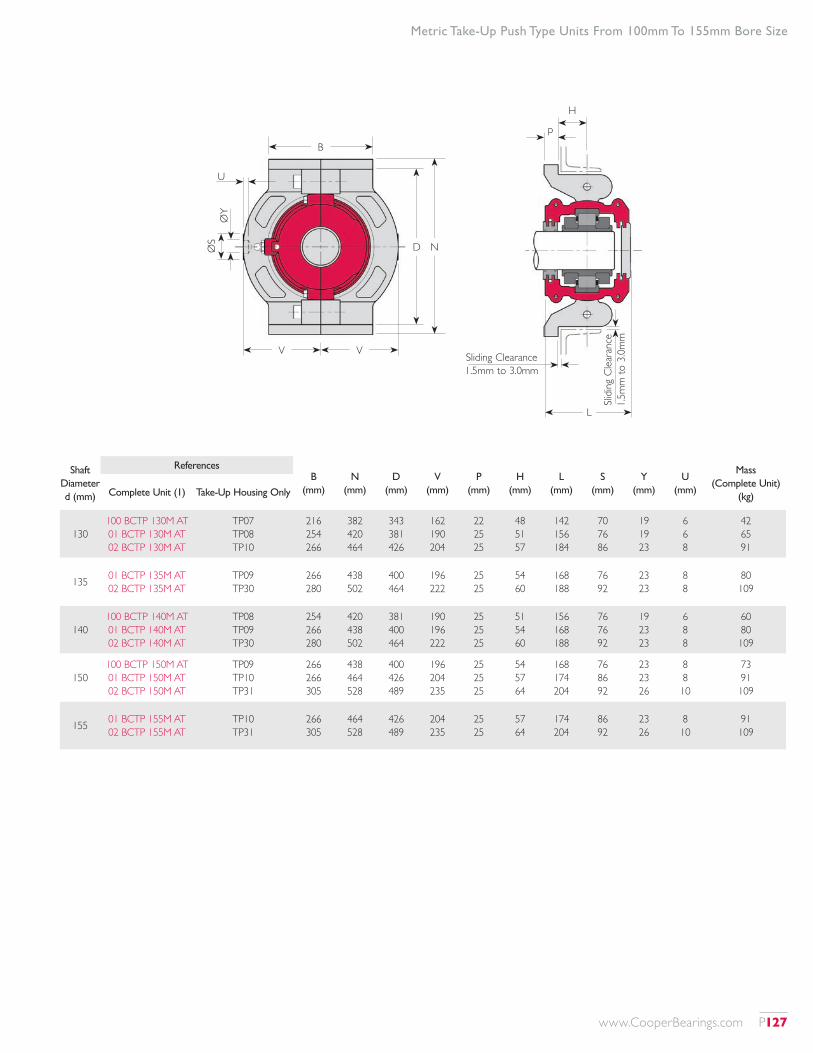
Metric Take-Up Push Type Units From 100mm To 155mm Bore Size
Shaft Diameter d (mm)
ReferencesB
(mm)N
(mm)D
(mm)V
(mm)P
(mm)H
(mm)L
(mm)S
(mm)Y
(mm)U
(mm)
Mass (Complete Unit)
(kg)Complete Unit (1) Take-Up Housing Only
130100 BCTP 130M AT 01 BCTP 130M AT 02 BCTP 130M AT
TP07 TP08 TP10
216 254 266
382 420 464
343 381 426
162 190 204
22 25 25
48 51 57
142 156 184
70 76 86
19 19 23
6 6 8
42 65 91
135 01 BCTP 135M AT 02 BCTP 135M AT
TP09 TP30
266 280
438 502
400 464
196 222
25 25
54 60
168 188
76 92
23 23
8 8
80 109
140100 BCTP 140M AT 01 BCTP 140M AT 02 BCTP 140M AT
TP08 TP09 TP30
254 266 280
420 438 502
381 400 464
190 196 222
25 25 25
51 54 60
156 168 188
76 76 92
19 23 23
6 8 8
60 80 109
150100 BCTP 150M AT 01 BCTP 150M AT 02 BCTP 150M AT
TP09 TP10 TP31
266 266 305
438 464 528
400 426 489
196 204 235
25 25 25
54 57 64
168 174 204
76 86 92
23 23 26
8 8 10
73 91 109
155 01 BCTP 155M AT 02 BCTP 155M AT
TP10 TP31
266 305
464 528
426 489
204 235
25 25
57 64
174 204
86 92
23 26
8 10
91 109
B
V V
U
D NØS
ØY
L
H
p
Sliding Clearance 1.5mm to 3.0mm
Slidi
ng C
leara
nce
1.5m
m to
3.0m
m
www.CooperBearings.com P127
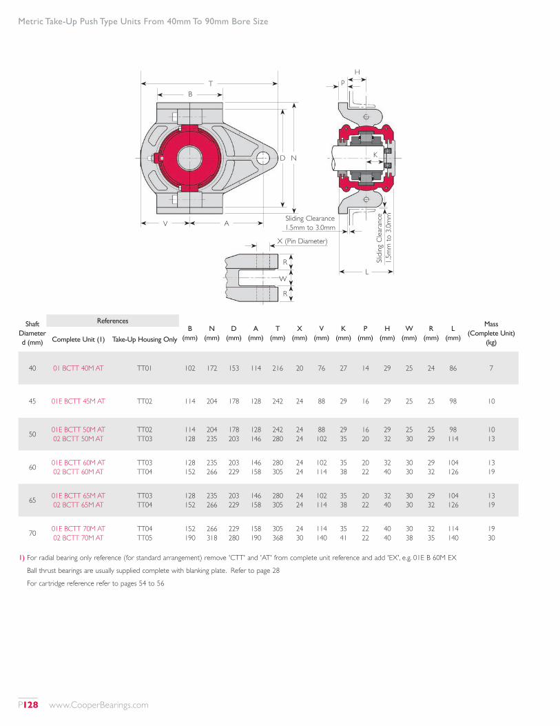
Metric Take-Up Push Type Units From 40mm To 90mm Bore Size
Shaft Diameter d (mm)
ReferencesB
(mm)N
(mm)D
(mm)A
(mm)T
(mm)X
(mm)V
(mm)K
(mm)P
(mm)H
(mm)W
(mm)R
(mm)L
(mm)
Mass (Complete Unit)
(kg)Complete Unit (1) Take-Up Housing Only
40 01 BCTT 40M AT TT01 102 172 153 114 216 20 76 27 14 29 25 24 86 7
45 01E BCTT 45M AT TT02 114 204 178 128 242 24 88 29 16 29 25 25 98 10
50 01E BCTT 50M AT 02 BCTT 50M AT
TT02 TT03
114 128
204 235
178 203
128 146
242 280
24 24
88 102
29 35
16 20
29 32
25 30
25 29
98 114
10 13
60 01E BCTT 60M AT 02 BCTT 60M AT
TT03 TT04
128 152
235 266
203 229
146 158
280 305
24 24
102 114
35 38
20 22
32 40
30 30
29 32
104 126
13 19
65 01E BCTT 65M AT 02 BCTT 65M AT
TT03 TT04
128 152
235 266
203 229
146 158
280 305
24 24
102 114
35 38
20 22
32 40
30 30
29 32
104 126
13 19
70 01E BCTT 70M AT 02 BCTT 70M AT
TT04 TT05
152 190
266 318
229 280
158 190
305 368
24 30
114 140
35 41
22 22
40 40
30 38
32 35
114 140
19 30
1) For radial bearing only reference (for standard arrangement) remove 'CTT' and 'AT' from complete unit reference and add 'EX', e.g. 01E B 60M EX
Ball thrust bearings are usually supplied complete with blanking plate. Refer to page 28
For cartridge reference refer to pages 54 to 56
K
L
D N
Hp
R
W
R
X (Pin Diameter)
Slidi
ng C
leara
nce
1.5m
m to
3.0m
mSliding Clearance 1.5mm to 3.0mm
B
V A
T
P128 www.CooperBearings.com
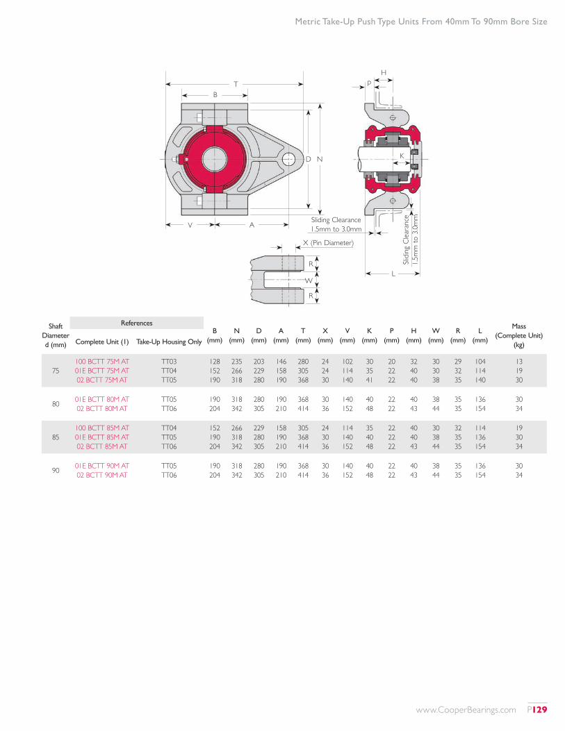
Metric Take-Up Push Type Units From 40mm To 90mm Bore Size
Shaft Diameter d (mm)
ReferencesB
(mm)N
(mm)D
(mm)A
(mm)T
(mm)X
(mm)V
(mm)K
(mm)P
(mm)H
(mm)W
(mm)R
(mm)L
(mm)
Mass (Complete Unit)
(kg)Complete Unit (1) Take-Up Housing Only
75100 BCTT 75M AT 01E BCTT 75M AT 02 BCTT 75M AT
TT03 TT04 TT05
128 152 190
235 266 318
203 229 280
146 158 190
280 305 368
24 24 30
102 114 140
30 35 41
20 22 22
32 40 40
30 30 38
29 32 35
104 114 140
13 19 30
80 01E BCTT 80M AT 02 BCTT 80M AT
TT05 TT06
190 204
318 342
280 305
190 210
368 414
30 36
140 152
40 48
22 22
40 43
38 44
35 35
136 154
30 34
85100 BCTT 85M AT 01E BCTT 85M AT 02 BCTT 85M AT
TT04 TT05 TT06
152 190 204
266 318 342
229 280 305
158 190 210
305 368 414
24 30 36
114 140 152
35 40 48
22 22 22
40 40 43
30 38 44
32 35 35
114 136 154
19 30 34
90 01E BCTT 90M AT 02 BCTT 90M AT
TT05 TT06
190 204
318 342
280 305
190 210
368 414
30 36
140 152
40 48
22 22
40 43
38 44
35 35
136 154
30 34
K
L
D N
Hp
R
W
R
X (Pin Diameter)
Slidi
ng C
leara
nce
1.5m
m to
3.0m
mSliding Clearance 1.5mm to 3.0mm
B
V A
T
www.CooperBearings.com P129
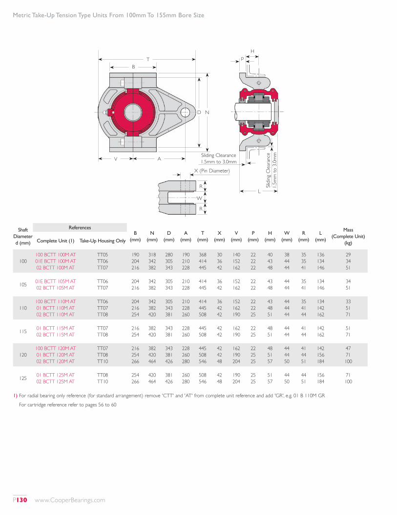
Metric Take-Up Tension Type Units From 100mm To 155mm Bore Size
1) For radial bearing only reference (for standard arrangement) remove 'CTT' and 'AT' from complete unit reference and add 'GR', e.g. 01 B 110M GR
For cartridge reference refer to pages 56 to 60
L
Hp
Slidi
ng C
leara
nce
1.5m
m to
3.0m
m
D N
R
W
R
X (Pin Diameter)
Sliding Clearance 1.5mm to 3.0mm
B
V A
T
Shaft Diameter d (mm)
ReferencesB
(mm)N
(mm)D
(mm)A
(mm)T
(mm)X
(mm)V
(mm)P
(mm)H
(mm)W
(mm)R
(mm)L
(mm)
Mass (Complete Unit)
(kg)Complete Unit (1) Take-Up Housing Only
100100 BCTT 100M AT 01E BCTT 100M AT 02 BCTT 100M AT
TT05 TT06 TT07
190 204 216
318 342 382
280 305 343
190 210 228
368 414 445
30 36 42
140 152 162
22 22 22
40 43 48
38 44 44
35 35 41
136 134 146
29 34 51
105 01E BCTT 105M AT 02 BCTT 105M AT
TT06 TT07
204 216
342 382
305 343
210 228
414 445
36 42
152 162
22 22
43 48
44 44
35 41
134 146
34 51
110100 BCTT 110M AT 01 BCTT 110M AT 02 BCTT 110M AT
TT06 TT07 TT08
204 216 254
342 382 420
305 343 381
210 228 260
414 445 508
36 42 42
152 162 190
22 22 25
43 48 51
44 44 44
35 41 44
134 142 162
33 51 71
115 01 BCTT 115M AT 02 BCTT 115M AT
TT07 TT08
216 254
382 420
343 381
228 260
445 508
42 42
162 190
22 25
48 51
44 44
41 44
142 162
51 71
120100 BCTT 120M AT 01 BCTT 120M AT 02 BCTT 120M AT
TT07 TT08 TT10
216 254 266
382 420 464
343 381 426
228 260 280
445 508 546
42 42 48
162 190 204
22 25 25
48 51 57
44 44 50
41 44 51
142 156 184
47 71 100
125 01 BCTT 125M AT 02 BCTT 125M AT
TT08 TT10
254 266
420 464
381 426
260 280
508 546
42 48
190 204
25 25
51 57
44 50
44 51
156 184
71 100
P130 www.CooperBearings.com

Metric Take-Up Tension Type Units From 100mm To 155mm Bore Size
L
Hp
Slidi
ng C
leara
nce
1.5m
m to
3.0m
m
D N
R
W
R
X (Pin Diameter)
Sliding Clearance 1.5mm to 3.0mm
B
V A
T
Shaft Diameter d (mm)
ReferencesB
(mm)N
(mm)D
(mm)A
(mm)T
(mm)X
(mm)V
(mm)P
(mm)H
(mm)W
(mm)R
(mm)L
(mm)
Mass (Complete Unit)
(kg)Complete Unit (1) Take-Up Housing Only
130100 BCTT 130M AT 01 BCTT 130M AT 02 BCTT 130M AT
TT07 TT08 TT10
216 254 266
382 420 464
343 381 426
228 260 280
445 508 546
42 42 48
162 190 204
22 25 25
48 51 57
44 44 50
41 44 51
142 156 184
47 71 100
135 01 BCTT 135M AT 02 BCTT 135M AT
TT09 TT30
266 280
438 502
400 464
266 298
514 584
42 48
196 222
25 25
54 60
44 50
48 54
168 188
89 119
140100 BCTT 140M AT 01 BCTT 140M AT 02 BCTT 140M AT
TT08 TT09 TT30
254 266 280
420 438 502
381 400 464
260 266 298
508 514 584
42 42 48
190 196 222
25 25 25
51 54 60
44 44 50
44 48 54
156 168 188
67 89 119
150100 BCTT 150M AT 01 BCTT 150M AT 02 BCTT 150M AT
TT09 TT10 TT31
266 266 305
438 464 528
400 426 489
266 280 312
514 546 616
42 48 48
196 204 235
25 25 25
54 57 64
44 50 50
48 51 57
168 174 204
82 100 141
155 01 BCTT 155M AT 02 BCTT 155M AT
TT10 TT31
266 305
464 528
426 489
280 312
546 616
48 48
204 235
25 25
57 64
50 50
51 57
174 204
100 141
www.CooperBearings.com P131
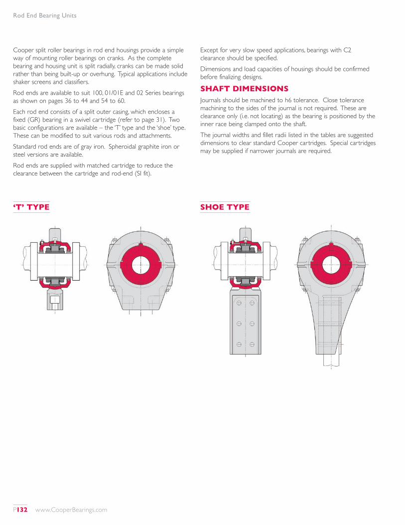
Rod End Bearing Units
Cooper split roller bearings in rod end housings provide a simple way of mounting roller bearings on cranks. As the complete bearing and housing unit is split radially, cranks can be made solid rather than being built-up or overhung. Typical applications include shaker screens and classifiers.Rod ends are available to suit 100, 01/01E and 02 Series bearings as shown on pages 36 to 44 and 54 to 60.Each rod end consists of a split outer casing, which encloses a fixed (GR) bearing in a swivel cartridge (refer to page 31). Two basic configurations are available – the ‘T’ type and the ‘shoe’ type. These can be modified to suit various rods and attachments.Standard rod ends are of gray iron. Spheroidal graphite iron or steel versions are available.Rod ends are supplied with matched cartridge to reduce the clearance between the cartridge and rod-end (SI fit).
Except for very slow speed applications, bearings with C2 clearance should be specified.Dimensions and load capacities of housings should be confirmed before finalizing designs.
SHAFT DIMENSIONSJournals should be machined to h6 tolerance. Close tolerance machining to the sides of the journal is not required. These are clearance only (i.e. not locating) as the bearing is positioned by the inner race being clamped onto the shaft.The journal widths and fillet radii listed in the tables are suggested dimensions to clear standard Cooper cartridges. Special cartridges may be supplied if narrower journals are required.
‘T’ TYPE SHOE TYPE
P132 www.CooperBearings.com
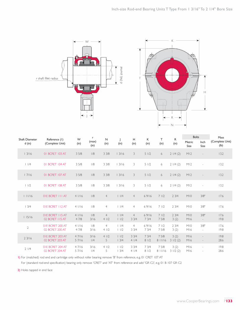
Inch-size Rod-end Bearing Units T Type From 1 3/16" To 2 1/4" Bore Size
W K
RJd
(h6)
jour
nal
N
H
Tr shaft fillet radius
Shaft Diameter d (in)
Reference (1) (Complete Unit)
W (in)
r (max) (in)
N (in)
J (in)
H (in)
K (in)
T (in)
R (in)
Bolts Mass (Complete Unit)
(lb)Metric Size
Inch Size
1 3/16 01 BCRET 103 AT 3 5/8 1/8 3 3/8 1 3/16 3 5 1/2 6 2 1/4 (2) M12 - 13.2
1 1/4 01 BCRET 104 AT 3 5/8 1/8 3 3/8 1 3/16 3 5 1/2 6 2 1/4 (2) M12 - 13.2
1 7/16 01 BCRET 107 AT 3 5/8 1/8 3 3/8 1 3/16 3 5 1/2 6 2 1/4 (2) M12 - 13.2
1 1/2 01 BCRET 108 AT 3 5/8 1/8 3 3/8 1 3/16 3 5 1/2 6 2 1/4 (2) M12 - 13.2
1 11/16 01E BCRET 111 AT 4 1/16 1/8 4 1 1/4 4 6 9/16 7 1/2 2 3/4 M10 3/8" 17.6
1 3/4 01E BCRET 112 AT 4 1/16 1/8 4 1 1/4 4 6 9/16 7 1/2 2 3/4 M10 3/8" 17.6
1 15/16 01E BCRET 115 AT 02 BCRET 115 AT
4 1/16 4 7/8
1/8 3/16
4 4 1/2
1 1/4 1 1/2
4 3 3/4
6 9/16 7 3/4
7 1/2 7 5/8
2 3/4 3 (2)
M10 M16
3/8" -
17.6 19.8
2 01E BCRET 200 AT 02 BCRET 200 AT
4 1/16 4 7/8
1/8 3/16
4 4 1/2
1 1/4 1 1/2
4 3 3/4
6 9/16 7 3/4
7 1/2 7 5/8
2 3/4 3 (2)
M10 M16
3/8" -
17.6 19.8
2 3/16 01E BCRET 203 AT 02 BCRET 203 AT
4 7/16 5 7/16
3/16 1/4
4 1/2 5
1 1/2 1 3/4
3 3/4 4 1/4
7 3/4 8 1/2
7 5/8 8 11/16
3 (2) 3 1/2 (2)
M16 M16
- -
19.8 28.6
2 1/4 01E BCRET 204 AT 02 BCRET 204 AT
4 7/16 5 7/16
3/16 1/4
4 1/2 5
1 1/2 1 3/4
3 3/4 4 1/4
7 3/4 8 1/2
7 5/8 8 11/16
3 (2) 3 1/2 (2)
M16 M16
- -
19.8 28.6
1) For (matched) rod end and cartridge only without roller bearing remove 'B' from reference, e.g. 01 CRET 107 AT
For (standard rod-end specification) bearing only remove 'CRET' and 'AT' from reference and add 'GR C2', e.g. 01 B 107 GR C2
2) Holes tapped in end face
www.CooperBearings.com P133
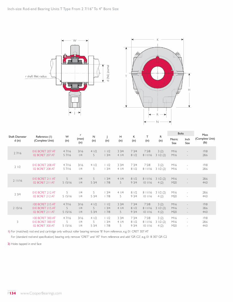
Inch-size Rod-end Bearing Units T Type From 2 7/16" To 4" Bore Size
Shaft Diameter d (in)
Reference (1) (Complete Unit)
W (in)
r (max) (in)
N (in)
J (in)
H (in)
K (in)
T (in)
R (in)
Bolts Mass (Complete Unit)
(lb)Metric Size
Inch Size
2 7/16 01E BCRET 207 AT 02 BCRET 207 AT
4 7/16 5 7/16
3/16 1/4
4 1/2 5
1 1/2 1 3/4
3 3/4 4 1/4
7 3/4 8 1/2
7 5/8 8 11/16
3 (2) 3 1/2 (2)
M16 M16
- -
19.8 28.6
2 1/2 01E BCRET 208 AT 02 BCRET 208 AT
4 7/16 5 7/16
3/16 1/4
4 1/2 5
1 1/2 1 3/4
3 3/4 4 1/4
7 3/4 8 1/2
7 5/8 8 11/16
3 (2) 3 1/2 (2)
M16 M16
- -
19.8 28.6
2 11/16 01E BCRET 211 AT 02 BCRET 211 AT
5 5 15/16
1/4 1/4
5 5 3/4
1 3/4 1 7/8
4 1/4 5
8 1/2 9 3/4
8 11/16 10 1/16
3 1/2 (2) 4 (2)
M16 M20
- -
28.6 44.0
2 3/4 01E BCRET 212 AT 02 BCRET 212 AT
5 5 15/16
1/4 1/4
5 5 3/4
1 3/4 1 7/8
4 1/4 5
8 1/2 9 3/4
8 11/16 10 1/16
3 1/2 (2) 4 (2)
M16 M20
- -
28.6 44.0
2 15/16100 BCRET 215 AT 01E BCRET 215 AT 02 BCRET 211 AT
4 7/16 5
5 15/16
3/16 1/4 1/4
4 1/2 5
5 3/4
1 1/2 1 3/4 1 7/8
3 3/4 4 1/4
5
7 3/4 8 1/2 9 3/4
7 5/8 8 11/16 10 1/16
3 (2) 3 1/2 (2)
4 (2)
M16 M16 M20
- - -
19.8 28.6 44.0
3100 BCRET 300 AT 01E BCRET 300 AT 02 BCRET 300 AT
4 7/16 5
5 15/16
3/16 1/4 1/4
4 1/2 5
5 3/4
1 1/2 1 3/4 1 7/8
3 3/4 4 1/4
5
7 3/4 8 1/2 9 3/4
7 5/8 8 11/16 10 1/16
3 (2) 3 1/2 (2)
4 (2)
M16 M16 M20
- - -
19.8 28.6 44.0
1) For (matched) rod end and cartridge only without roller bearing remove 'B' from reference, e.g. 01 CRET 307 AT
For (standard rod-end specification) bearing only remove 'CRET' and 'AT' from reference and add 'GR C2', e.g. 01 B 307 GR C2
2) Holes tapped in end face
W K
RJd
(h6)
jour
nal
N
H
Tr shaft fillet radius
P134 www.CooperBearings.com
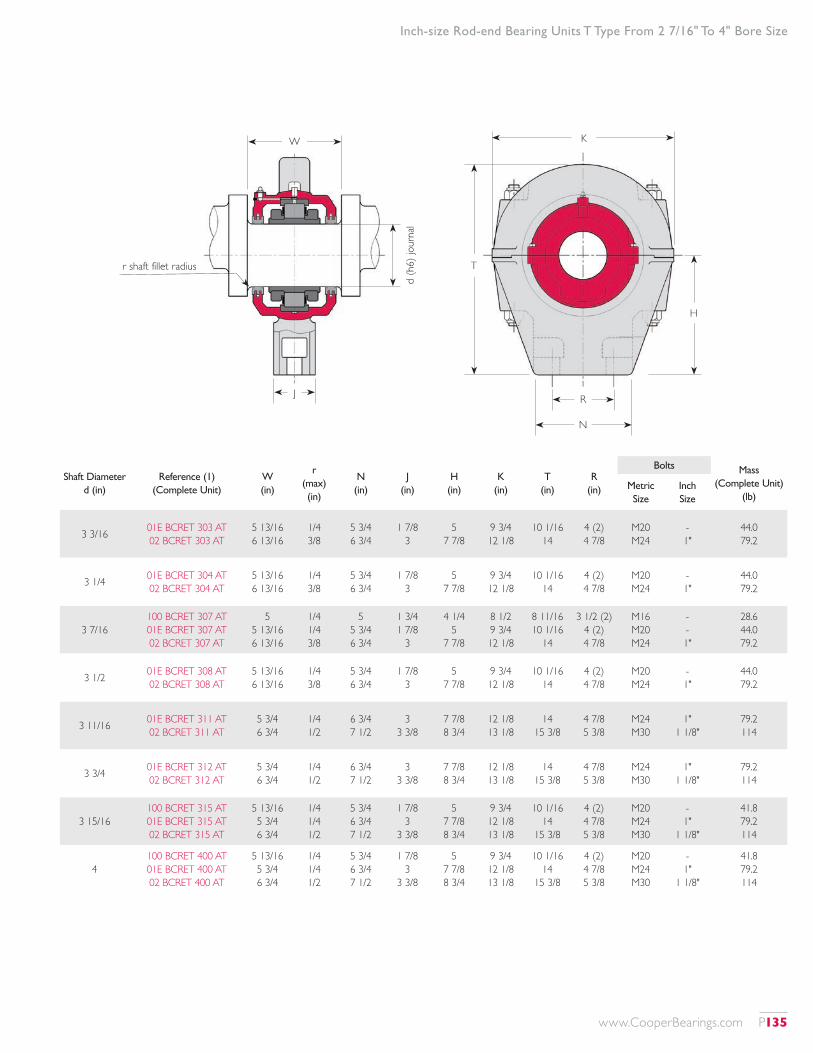
Inch-size Rod-end Bearing Units T Type From 2 7/16" To 4" Bore Size
Shaft Diameter d (in)
Reference (1) (Complete Unit)
W (in)
r (max) (in)
N (in)
J (in)
H (in)
K (in)
T (in)
R (in)
Bolts Mass (Complete Unit)
(lb)Metric Size
Inch Size
3 3/16 01E BCRET 303 AT 02 BCRET 303 AT
5 13/16 6 13/16
1/4 3/8
5 3/4 6 3/4
1 7/8 3
5 7 7/8
9 3/4 12 1/8
10 1/16 14
4 (2) 4 7/8
M20 M24
- 1"
44.0 79.2
3 1/4 01E BCRET 304 AT 02 BCRET 304 AT
5 13/16 6 13/16
1/4 3/8
5 3/4 6 3/4
1 7/8 3
5 7 7/8
9 3/4 12 1/8
10 1/16 14
4 (2) 4 7/8
M20 M24
- 1"
44.0 79.2
3 7/16100 BCRET 307 AT 01E BCRET 307 AT 02 BCRET 307 AT
5 5 13/16 6 13/16
1/4 1/4 3/8
5 5 3/4 6 3/4
1 3/4 1 7/8
3
4 1/4 5
7 7/8
8 1/2 9 3/4 12 1/8
8 11/16 10 1/16
14
3 1/2 (2) 4 (2) 4 7/8
M16 M20 M24
- - 1"
28.6 44.0 79.2
3 1/2 01E BCRET 308 AT 02 BCRET 308 AT
5 13/16 6 13/16
1/4 3/8
5 3/4 6 3/4
1 7/8 3
5 7 7/8
9 3/4 12 1/8
10 1/16 14
4 (2) 4 7/8
M20 M24
- 1"
44.0 79.2
3 11/16 01E BCRET 311 AT 02 BCRET 311 AT
5 3/4 6 3/4
1/4 1/2
6 3/4 7 1/2
3 3 3/8
7 7/8 8 3/4
12 1/8 13 1/8
14 15 3/8
4 7/8 5 3/8
M24 M30
1" 1 1/8"
79.2 114
3 3/4 01E BCRET 312 AT 02 BCRET 312 AT
5 3/4 6 3/4
1/4 1/2
6 3/4 7 1/2
3 3 3/8
7 7/8 8 3/4
12 1/8 13 1/8
14 15 3/8
4 7/8 5 3/8
M24 M30
1" 1 1/8"
79.2 114
3 15/16100 BCRET 315 AT 01E BCRET 315 AT 02 BCRET 315 AT
5 13/16 5 3/4 6 3/4
1/4 1/4 1/2
5 3/4 6 3/4 7 1/2
1 7/8 3
3 3/8
5 7 7/8 8 3/4
9 3/4 12 1/8 13 1/8
10 1/16 14
15 3/8
4 (2) 4 7/8 5 3/8
M20 M24 M30
- 1"
1 1/8"
41.8 79.2 114
4100 BCRET 400 AT 01E BCRET 400 AT 02 BCRET 400 AT
5 13/16 5 3/4 6 3/4
1/4 1/4 1/2
5 3/4 6 3/4 7 1/2
1 7/8 3
3 3/8
5 7 7/8 8 3/4
9 3/4 12 1/8 13 1/8
10 1/16 14
15 3/8
4 (2) 4 7/8 5 3/8
M20 M24 M30
- 1"
1 1/8"
41.8 79.2 114
W K
RJd
(h6)
jour
nal
N
H
Tr shaft fillet radius
www.CooperBearings.com P135
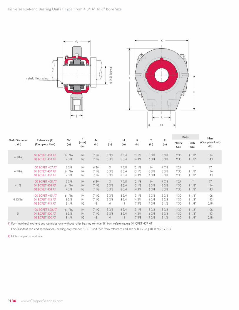
Inch-size Rod-end Bearing Units T Type From 4 3/16" To 6" Bore Size
Shaft Diameter d (in)
Reference (1) (Complete Unit)
W (in)
r (max) (in)
N (in)
J (in)
H (in)
K (in)
T (in)
R (in)
Bolts Mass (Complete Unit)
(lb)Metric Size
Inch Size
4 3/16 01 BCRET 403 AT 02 BCRET 403 AT
6 1/16 7 3/8
1/4 1/2
7 1/2 7 1/2
3 3/8 3 3/8
8 3/4 8 3/4
13 1/8 14 3/4
15 3/8 16 3/4
5 3/8 5 3/8
M30 M30
1 1/8" 1 1/8"
114 143
4 7/16100 BCRET 407 AT 01 BCRET 407 AT 02 BCRET 407 AT
5 3/4 6 1/16 7 3/8
1/4 1/4 1/2
6 3/4 7 1/2 7 1/2
3 3 3/8 3 3/8
7 7/8 8 3/4 8 3/4
12 1/8 13 1/8 14 3/4
14 15 3/8 16 3/4
4 7/8 5 3/8 5 3/8
M24 M30 M30
1" 1 1/8" 1 1/8"
77 114 143
4 1/2100 BCRET 408 AT 01 BCRET 408 AT 02 BCRET 408 AT
5 3/4 6 1/16 7 3/8
1/4 1/4 1/2
6 3/4 7 1/2 7 1/2
3 3 3/8 3 3/8
7 7/8 8 3/4 8 3/4
12 1/8 13 1/8 14 3/4
14 15 3/8 16 3/4
4 7/8 5 3/8 5 3/8
M24 M30 M30
1" 1 1/8" 1 1/8"
77 114 143
4 15/16100 BCRET 415 AT 01 BCRET 415 AT 02 BCRET 415 AT
6 1/16 6 5/8 8 1/4
1/4 1/4 1/2
7 1/2 7 1/2
8
3 3/8 3 3/8
4
8 3/4 8 3/4 11
13 1/8 14 3/4 17 3/8
15 3/8 16 3/4 19 3/4
5 3/8 5 3/8 5 1/2
M30 M30 M30
1 1/8" 1 1/8" 1 1/4"
106 143 218
5100 BCRET 500 AT 01 BCRET 500 AT 02 BCRET 500 AT
6 1/16 6 5/8 8 1/4
1/4 1/4 1/2
7 1/2 7 1/2
8
3 3/8 3 3/8
4
8 3/4 8 3/4 11
13 1/8 14 3/4 17 3/8
15 3/8 16 3/4 19 3/4
5 3/8 5 3/8 5 1/2
M30 M30 M30
1 1/8" 1 1/8" 1 1/4"
106 143 218
1) For (matched) rod end and cartridge only without roller bearing remove 'B' from reference, e.g. 01 CRET 407 AT
For (standard rod-end specification) bearing only remove 'CRET' and 'AT' from reference and add 'GR C2', e.g. 01 B 407 GR C2
2) Holes tapped in end face
W K
RJd
(h6)
jour
nal
N
H
Tr shaft fillet radius
P136 www.CooperBearings.com
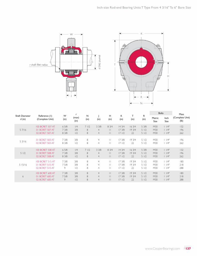
Inch-size Rod-end Bearing Units T Type From 4 3/16" To 6" Bore Size
Shaft Diameter d (in)
Reference (1) (Complete Unit)
W (in)
r (max) (in)
N (in)
J (in)
H (in)
K (in)
T (in)
R (in)
Bolts Mass (Complete Unit)
(lb)Metric Size
Inch Size
5 7/16100 BCRET 507 AT 01 BCRET 507 AT 02 BCRET 507 AT
6 5/8 7 3/8 8 3/8
1/4 3/8 1/2
7 1/2 8 8
3 3/8 4 4
8 3/4 11 11
14 3/4 17 3/8 17 1/2
16 3/4 19 3/4
22
5 3/8 5 1/2 5 1/2
M30 M30 M30
1 1/4" 1 1/4" 1 1/4"
132 196 262
5 3/16 01 BCRET 503 AT 02 BCRET 503 AT
7 3/8 8 3/8
3/8 1/2
8 8
4 4
11 11
17 3/8 17 1/2
19 3/4 22
5 1/2 5 1/2
M30 M30
1 1/4" 1 1/4"
196 262
5 1/2100 BCRET 508 AT 01 BCRET 508 AT 02 BCRET 508 AT
6 5/8 7 3/8 8 3/8
1/4 3/8 1/2
7 1/2 8 8
3 3/8 4 4
8 3/4 11 11
14 3/4 17 3/8 17 1/2
16 3/4 19 3/4
22
5 3/8 5 1/2 5 1/2
M30 M30 M30
1 1/4" 1 1/4" 1 1/4"
132 196 262
5 15/16100 BCRET 515 AT 01 BCRET 515 AT 02 BCRET 515 AT
7 3/8 7 5/8
9
3/8 3/8 1/2
8 8 8
4 4 4
11 11 11
17 3/8 17 3/8 17 1/2
19 3/4 19 3/4
22
5 1/2 5 1/2 5 1/2
M30 M30 M30
1 1/4" 1 1/4" 1 1/4"
180 218 288
6100 BCRET 600 AT 01 BCRET 600 AT 02 BCRET 600 AT
7 3/8 7 5/8
9
3/8 3/8 1/2
8 8 8
4 4 4
11 11 11
17 3/8 17 3/8 17 1/2
19 3/4 19 3/4
22
5 1/2 5 1/2 5 1/2
M30 M30 M30
1 1/4" 1 1/4" 1 1/4"
180 218 288
W K
RJd
(h6)
jour
nal
N
H
Tr shaft fillet radius
www.CooperBearings.com P137
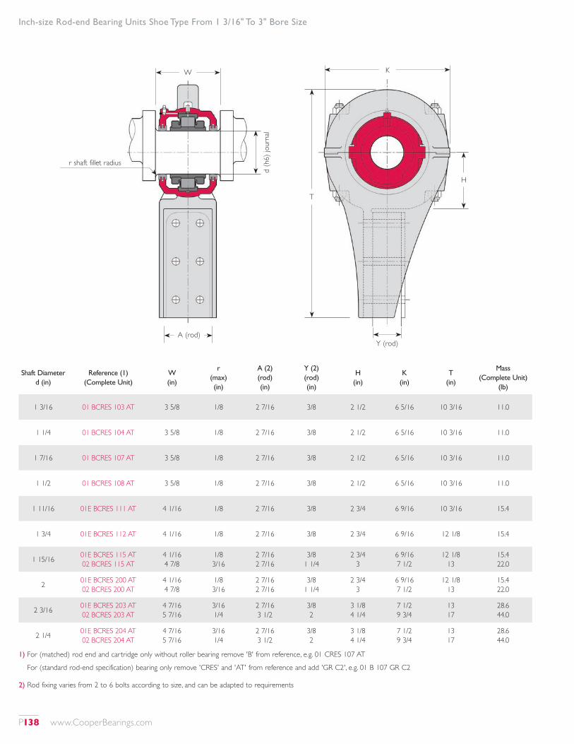
Inch-size Rod-end Bearing Units Shoe Type From 1 3/16" To 3" Bore Size
Shaft Diameter d (in)
Reference (1) (Complete Unit)
W (in)
r (max) (in)
A (2) (rod) (in)
Y (2) (rod) (in)
H (in)
K (in)
T (in)
Mass (Complete Unit)
(lb)
1 3/16 01 BCRES 103 AT 3 5/8 1/8 2 7/16 3/8 2 1/2 6 5/16 10 3/16 11.0
1 1/4 01 BCRES 104 AT 3 5/8 1/8 2 7/16 3/8 2 1/2 6 5/16 10 3/16 11.0
1 7/16 01 BCRES 107 AT 3 5/8 1/8 2 7/16 3/8 2 1/2 6 5/16 10 3/16 11.0
1 1/2 01 BCRES 108 AT 3 5/8 1/8 2 7/16 3/8 2 1/2 6 5/16 10 3/16 11.0
1 11/16 01E BCRES 111 AT 4 1/16 1/8 2 7/16 3/8 2 3/4 6 9/16 10 3/16 15.4
1 3/4 01E BCRES 112 AT 4 1/16 1/8 2 7/16 3/8 2 3/4 6 9/16 12 1/8 15.4
1 15/16 01E BCRES 115 AT 02 BCRES 115 AT
4 1/16 4 7/8
1/8 3/16
2 7/16 2 7/16
3/8 1 1/4
2 3/4 3
6 9/16 7 1/2
12 1/8 13
15.4 22.0
2 01E BCRES 200 AT 02 BCRES 200 AT
4 1/16 4 7/8
1/8 3/16
2 7/16 2 7/16
3/8 1 1/4
2 3/4 3
6 9/16 7 1/2
12 1/8 13
15.4 22.0
2 3/16 01E BCRES 203 AT 02 BCRES 203 AT
4 7/16 5 7/16
3/16 1/4
2 7/16 3 1/2
3/8 2
3 1/8 4 1/4
7 1/2 9 3/4
13 17
28.6 44.0
2 1/4 01E BCRES 204 AT 02 BCRES 204 AT
4 7/16 5 7/16
3/16 1/4
2 7/16 3 1/2
3/8 2
3 1/8 4 1/4
7 1/2 9 3/4
13 17
28.6 44.0
1) For (matched) rod end and cartridge only without roller bearing remove 'B' from reference, e.g. 01 CRES 107 AT
For (standard rod-end specification) bearing only remove 'CRES' and 'AT' from reference and add 'GR C2', e.g. 01 B 107 GR C2
2) Rod fixing varies from 2 to 6 bolts according to size, and can be adapted to requirements
W K
Y (rod)A (rod)
d (h
6) jo
urna
l
H
T
r shaft fillet radius
P138 www.CooperBearings.com
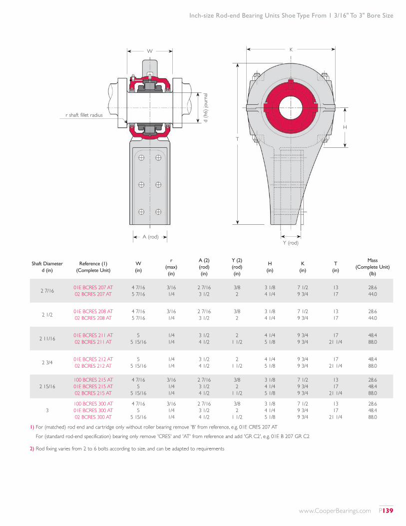
Inch-size Rod-end Bearing Units Shoe Type From 1 3/16" To 3" Bore Size
Shaft Diameter d (in)
Reference (1) (Complete Unit)
W (in)
r (max) (in)
A (2) (rod) (in)
Y (2) (rod) (in)
H (in)
K (in)
T (in)
Mass (Complete Unit)
(lb)
2 7/16 01E BCRES 207 AT 02 BCRES 207 AT
4 7/16 5 7/16
3/16 1/4
2 7/16 3 1/2
3/8 2
3 1/8 4 1/4
7 1/2 9 3/4
13 17
28.6 44.0
2 1/2 01E BCRES 208 AT 02 BCRES 208 AT
4 7/16 5 7/16
3/16 1/4
2 7/16 3 1/2
3/8 2
3 1/8 4 1/4
7 1/2 9 3/4
13 17
28.6 44.0
2 11/16 01E BCRES 211 AT 02 BCRES 211 AT
5 5 15/16
1/4 1/4
3 1/2 4 1/2
2 1 1/2
4 1/4 5 1/8
9 3/4 9 3/4
17 21 1/4
48.4 88.0
2 3/4 01E BCRES 212 AT 02 BCRES 212 AT
5 5 15/16
1/4 1/4
3 1/2 4 1/2
2 1 1/2
4 1/4 5 1/8
9 3/4 9 3/4
17 21 1/4
48.4 88.0
2 15/16100 BCRES 215 AT 01E BCRES 215 AT 02 BCRES 215 AT
4 7/16 5
5 15/16
3/16 1/4 1/4
2 7/16 3 1/2 4 1/2
3/8 2
1 1/2
3 1/8 4 1/4 5 1/8
7 1/2 9 3/4 9 3/4
13 17
21 1/4
28.6 48.4 88.0
3100 BCRES 300 AT 01E BCRES 300 AT 02 BCRES 300 AT
4 7/16 5
5 15/16
3/16 1/4 1/4
2 7/16 3 1/2 4 1/2
3/8 2
1 1/2
3 1/8 4 1/4 5 1/8
7 1/2 9 3/4 9 3/4
13 17
21 1/4
28.6 48.4 88.0
1) For (matched) rod end and cartridge only without roller bearing remove 'B' from reference, e.g. 01E CRES 207 AT
For (standard rod-end specification) bearing only remove 'CRES' and 'AT' from reference and add 'GR C2', e.g. 01E B 207 GR C2
2) Rod fixing varies from 2 to 6 bolts according to size, and can be adapted to requirements
W K
Y (rod)A (rod)
d (h
6) jo
urna
l
H
T
r shaft fillet radius
www.CooperBearings.com P139

Inch-size Rod-end Bearing Units Shoe Type From 3 3/16" To 4 15/16" Bore Size
Shaft Diameter d (in)
Reference (1) (Complete Unit)
W (in)
r (max) (in)
A (2) (rod) (in)
Y (2) (rod) (in)
H (in)
K (in)
T (in)
Mass (Complete Unit)
(lb)
3 3/16 01E BCRES 303 AT 02 BCRES 303 AT
5 13/16 6 13/16
1/4 3/8
3 15/16 5
2 3
5 1/4 5 7/8
10 3/8 13 1/8
23 3/4 24
94.6 136
3 1/4 01E BCRES 304 AT 02 BCRES 304 AT
5 13/16 6 13/16
1/4 3/8
3 15/16 5
2 3
5 1/4 5 7/8
10 3/8 13 1/8
23 3/4 24
94.6 136
3 7/16100 BCRES 307 AT 01E BCRES 307 AT 02 BCRES 307 AT
5 5 13/16 6 13/16
1/4 1/4 3/8
3 1/2 3 15/16
5
2 2 3
4 1/4 5 1/4 5 7/8
9 3/4 10 3/8 13 1/8
17 23 3/4
24
50.6 94.6 136
3 1/2 01E BCRES 308 AT 02 BCRES 308 AT
5 13/16 6 13/16
1/4 3/8
3 15/16 5
2 3
5 1/4 5 7/8
10 3/8 13 1/8
23 3/4 24
94.6 136
3 11/16 01E BCRES 311 AT 02 BCRES 311 AT
5 3/4 6 3/4
1/4 1/2
3 15/16 5
2 5/16 3
4 15/16 5 7/8
12 1/8 13 15/16
22 1/2 24 5/16
96.8 156
3 3/4 01E BCRES 312 AT 02 BCRES 312 AT
5 3/4 6 3/4
1/4 1/2
3 15/16 5
2 5/16 3
4 15/16 5 7/8
12 1/8 13 15/16
22 1/2 24 5/16
96.8 156
3 15/16100 BCRES 315 AT 01E BCRES 315 AT 02 BCRES 315 AT
5 13/16 5 3/4 6 3/4
1/4 1/4 1/2
4 1/2 3 15/16
5
1 1/2 2 5/16
3
5 1/8 4 15/16 5 7/8
9 3/4 12 1/8
13 15/16
21 1/4 22 1/2 24 5/16
79.2 96.8 156
1) For (matched) rod end and cartridge only without roller bearing remove 'B' from reference, e.g. 01 CRES 407 AT
For (standard rod-end specification) bearing only remove 'CRES' and 'AT' from reference and add 'GR C2', e.g. 01 B 407 GR C2
2) Rod fixing varies from 2 to 6 bolts according to size, and can be adapted to requirements
W K
Y (rod)A (rod)
d (h
6) jo
urna
l
H
T
r shaft fillet radius
P140 www.CooperBearings.com
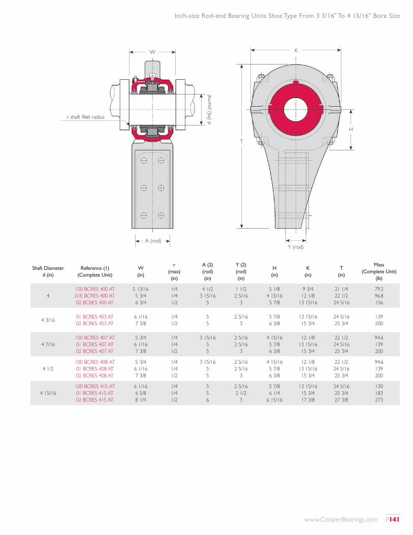
Inch-size Rod-end Bearing Units Shoe Type From 3 3/16" To 4 15/16" Bore Size
Shaft Diameter d (in)
Reference (1) (Complete Unit)
W (in)
r (max) (in)
A (2) (rod) (in)
Y (2) (rod) (in)
H (in)
K (in)
T (in)
Mass (Complete Unit)
(lb)
4100 BCRES 400 AT 01E BCRES 400 AT 02 BCRES 400 AT
5 13/16 5 3/4 6 3/4
1/4 1/4 1/2
4 1/2 3 15/16
5
1 1/2 2 5/16
3
5 1/8 4 15/16 5 7/8
9 3/4 12 1/8
13 15/16
21 1/4 22 1/2 24 5/16
79.2 96.8 156
4 3/16 01 BCRES 403 AT 02 BCRES 403 AT
6 1/16 7 3/8
1/4 1/2
5 5
2 5/16 3
5 7/8 6 3/8
13 15/16 15 3/4
24 5/16 25 3/4
139 200
4 7/16100 BCRES 407 AT 01 BCRES 407 AT 02 BCRES 407 AT
5 3/4 6 1/16 7 3/8
1/4 1/4 1/2
3 15/16 5 5
2 5/16 2 5/16
3
4 15/16 5 7/8 6 3/8
12 1/8 13 15/16 15 3/4
22 1/2 24 5/16 25 3/4
94.6 139 200
4 1/2100 BCRES 408 AT 01 BCRES 408 AT 02 BCRES 408 AT
5 3/4 6 1/16 7 3/8
1/4 1/4 1/2
3 15/16 5 5
2 5/16 2 5/16
3
4 15/16 5 7/8 6 3/8
12 1/8 13 15/16 15 3/4
22 1/2 24 5/16 25 3/4
94.6 139 200
4 15/16100 BCRES 415 AT 01 BCRES 415 AT 02 BCRES 415 AT
6 1/16 6 5/8 8 1/4
1/4 1/4 1/2
5 5 6
2 5/16 2 1/2
3
5 7/8 6 1/4
6 15/16
13 15/16 15 3/4 17 3/8
24 5/16 25 3/4 27 3/8
130 183 273
W K
Y (rod)A (rod)
d (h
6) jo
urna
l
H
T
r shaft fillet radius
www.CooperBearings.com P141
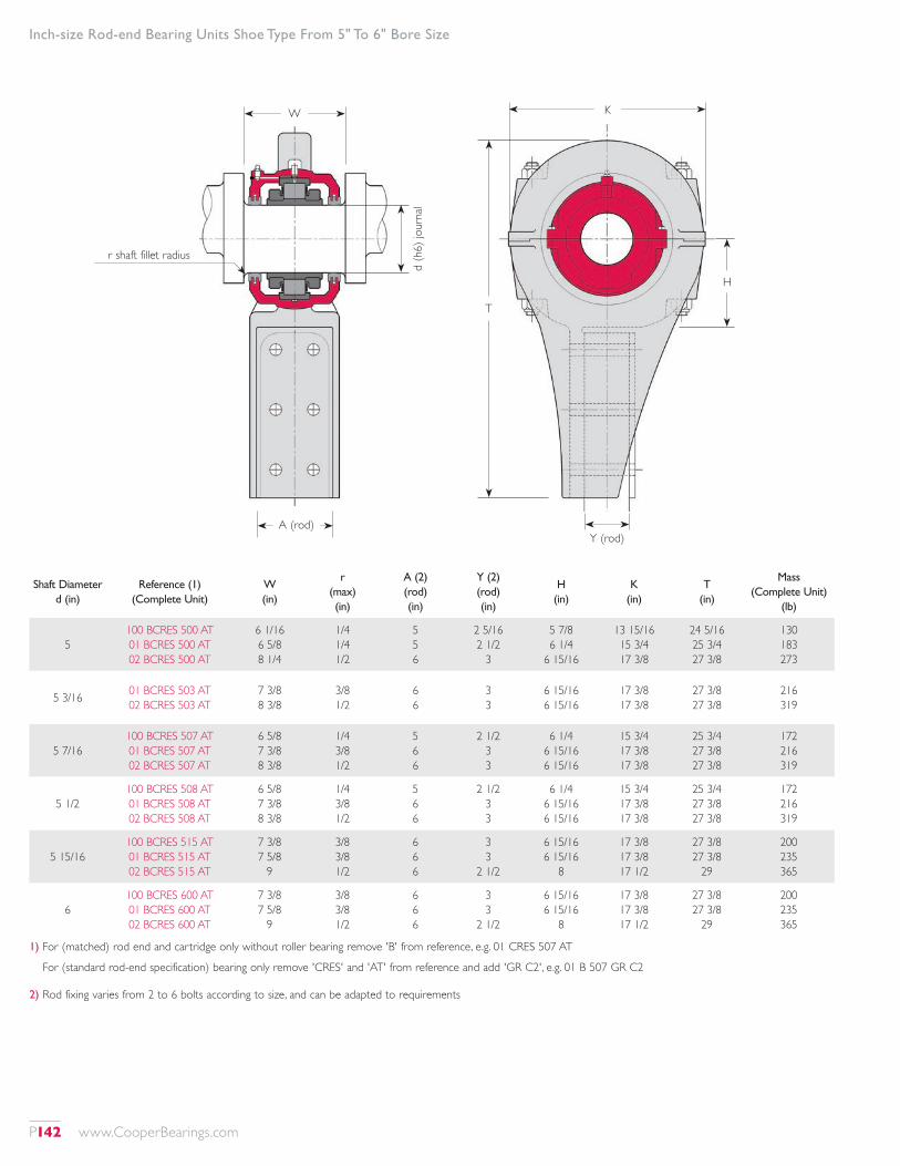
Inch-size Rod-end Bearing Units Shoe Type From 5" To 6" Bore Size
Shaft Diameter d (in)
Reference (1) (Complete Unit)
W (in)
r (max) (in)
A (2) (rod) (in)
Y (2) (rod) (in)
H (in)
K (in)
T (in)
Mass (Complete Unit)
(lb)
5100 BCRES 500 AT 01 BCRES 500 AT 02 BCRES 500 AT
6 1/16 6 5/8 8 1/4
1/4 1/4 1/2
5 5 6
2 5/16 2 1/2
3
5 7/8 6 1/4
6 15/16
13 15/16 15 3/4 17 3/8
24 5/16 25 3/4 27 3/8
130 183 273
5 3/16 01 BCRES 503 AT 02 BCRES 503 AT
7 3/8 8 3/8
3/8 1/2
6 6
3 3
6 15/16 6 15/16
17 3/8 17 3/8
27 3/8 27 3/8
216 319
5 7/16100 BCRES 507 AT 01 BCRES 507 AT 02 BCRES 507 AT
6 5/8 7 3/8 8 3/8
1/4 3/8 1/2
5 6 6
2 1/2 3 3
6 1/4 6 15/16 6 15/16
15 3/4 17 3/8 17 3/8
25 3/4 27 3/8 27 3/8
172 216 319
5 1/2100 BCRES 508 AT 01 BCRES 508 AT 02 BCRES 508 AT
6 5/8 7 3/8 8 3/8
1/4 3/8 1/2
5 6 6
2 1/2 3 3
6 1/4 6 15/16 6 15/16
15 3/4 17 3/8 17 3/8
25 3/4 27 3/8 27 3/8
172 216 319
5 15/16100 BCRES 515 AT 01 BCRES 515 AT 02 BCRES 515 AT
7 3/8 7 5/8
9
3/8 3/8 1/2
6 6 6
3 3
2 1/2
6 15/16 6 15/16
8
17 3/8 17 3/8 17 1/2
27 3/8 27 3/8
29
200 235 365
6100 BCRES 600 AT 01 BCRES 600 AT 02 BCRES 600 AT
7 3/8 7 5/8
9
3/8 3/8 1/2
6 6 6
3 3
2 1/2
6 15/16 6 15/16
8
17 3/8 17 3/8 17 1/2
27 3/8 27 3/8
29
200 235 365
1) For (matched) rod end and cartridge only without roller bearing remove 'B' from reference, e.g. 01 CRES 507 AT
For (standard rod-end specification) bearing only remove 'CRES' and 'AT' from reference and add 'GR C2', e.g. 01 B 507 GR C2
2) Rod fixing varies from 2 to 6 bolts according to size, and can be adapted to requirements
W K
Y (rod)A (rod)
d (h
6) jo
urna
l
H
T
r shaft fillet radius
P142 www.CooperBearings.com
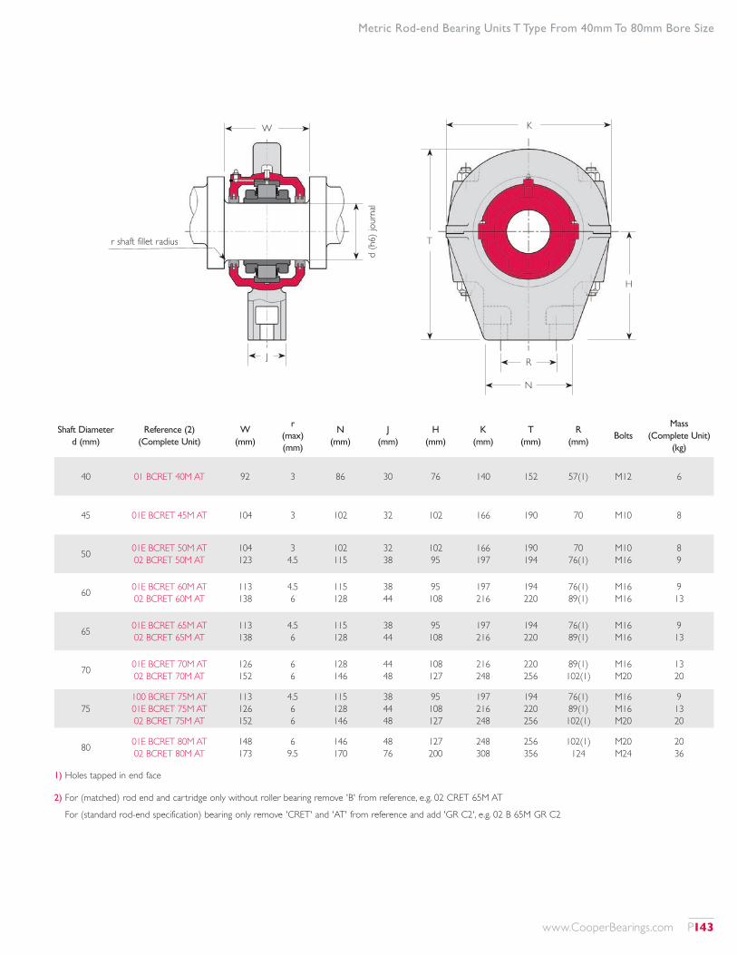
1) Holes tapped in end face
2) For (matched) rod end and cartridge only without roller bearing remove 'B' from reference, e.g. 02 CRET 65M AT
For (standard rod-end specification) bearing only remove 'CRET' and 'AT' from reference and add 'GR C2', e.g. 02 B 65M GR C2
Metric Rod-end Bearing Units T Type From 40mm To 80mm Bore Size
Shaft Diameter d (mm)
Reference (2) (Complete Unit)
W (mm)
r (max) (mm)
N (mm)
J (mm)
H (mm)
K (mm)
T (mm)
R (mm)
BoltsMass
(Complete Unit) (kg)
40 01 BCRET 40M AT 92 3 86 30 76 140 152 57(1) M12 6
45 01E BCRET 45M AT 104 3 102 32 102 166 190 70 M10 8
50 01E BCRET 50M AT 02 BCRET 50M AT
104 123
3 4.5
102 115
32 38
102 95
166 197
190 194
70 76(1)
M10 M16
8 9
60 01E BCRET 60M AT 02 BCRET 60M AT
113 138
4.5 6
115 128
38 44
95 108
197 216
194 220
76(1) 89(1)
M16 M16
9 13
65 01E BCRET 65M AT 02 BCRET 65M AT
113 138
4.5 6
115 128
38 44
95 108
197 216
194 220
76(1) 89(1)
M16 M16
9 13
70 01E BCRET 70M AT 02 BCRET 70M AT
126 152
6 6
128 146
44 48
108 127
216 248
220 256
89(1) 102(1)
M16 M20
13 20
75100 BCRET 75M AT 01E BCRET 75M AT 02 BCRET 75M AT
113 126 152
4.5 6 6
115 128 146
38 44 48
95 108 127
197 216 248
194 220 256
76(1) 89(1) 102(1)
M16 M16 M20
9 13 20
80 01E BCRET 80M AT 02 BCRET 80M AT
148 173
6 9.5
146 170
48 76
127 200
248 308
256 356
102(1) 124
M20 M24
20 36
W K
RJd
(h6)
jour
nal
N
H
Tr shaft fillet radius
www.CooperBearings.com P143
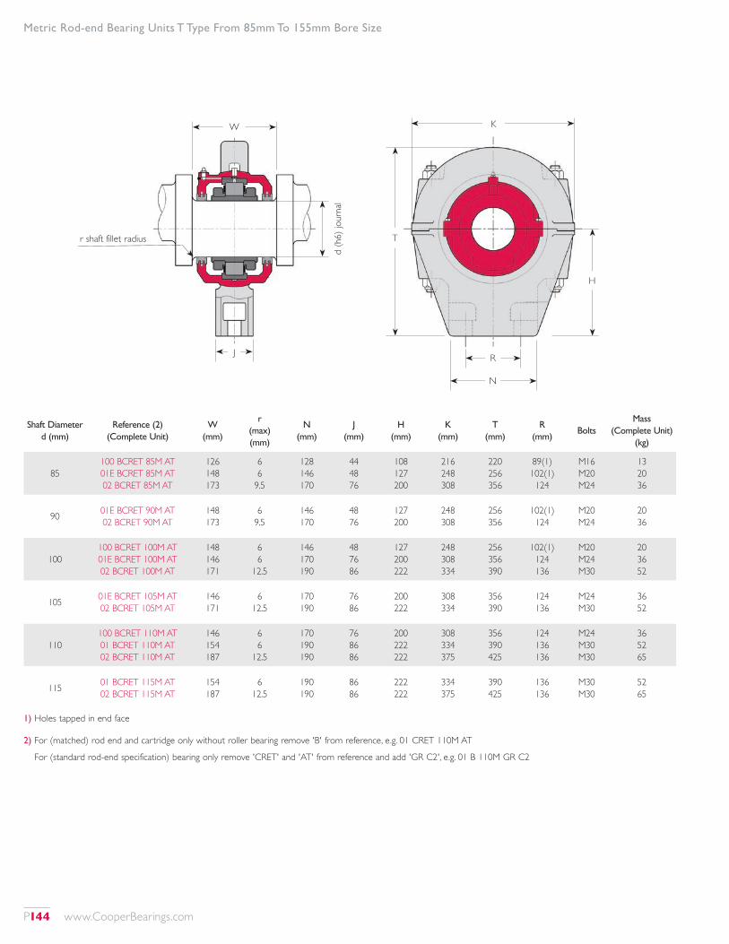
1) Holes tapped in end face
2) For (matched) rod end and cartridge only without roller bearing remove 'B' from reference, e.g. 01 CRET 110M AT
For (standard rod-end specification) bearing only remove 'CRET' and 'AT' from reference and add 'GR C2', e.g. 01 B 110M GR C2
Metric Rod-end Bearing Units T Type From 85mm To 155mm Bore Size
Shaft Diameter d (mm)
Reference (2) (Complete Unit)
W (mm)
r (max) (mm)
N (mm)
J (mm)
H (mm)
K (mm)
T (mm)
R (mm)
BoltsMass
(Complete Unit) (kg)
85100 BCRET 85M AT 01E BCRET 85M AT 02 BCRET 85M AT
126 148 173
6 6
9.5
128 146 170
44 48 76
108 127 200
216 248 308
220 256 356
89(1) 102(1) 124
M16 M20 M24
13 20 36
90 01E BCRET 90M AT 02 BCRET 90M AT
148 173
6 9.5
146 170
48 76
127 200
248 308
256 356
102(1) 124
M20 M24
20 36
100100 BCRET 100M AT 01E BCRET 100M AT 02 BCRET 100M AT
148 146 171
6 6
12.5
146 170 190
48 76 86
127 200 222
248 308 334
256 356 390
102(1) 124 136
M20 M24 M30
20 36 52
105 01E BCRET 105M AT 02 BCRET 105M AT
146 171
6 12.5
170 190
76 86
200 222
308 334
356 390
124 136
M24 M30
36 52
110100 BCRET 110M AT 01 BCRET 110M AT 02 BCRET 110M AT
146 154 187
6 6
12.5
170 190 190
76 86 86
200 222 222
308 334 375
356 390 425
124 136 136
M24 M30 M30
36 52 65
115 01 BCRET 115M AT 02 BCRET 115M AT
154 187
6 12.5
190 190
86 86
222 222
334 375
390 425
136 136
M30 M30
52 65
W K
RJd
(h6)
jour
nal
N
H
Tr shaft fillet radius
P144 www.CooperBearings.com
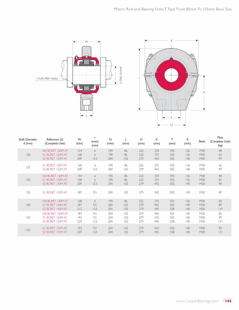
Metric Rod-end Bearing Units T Type From 85mm To 155mm Bore Size
Shaft Diameter d (mm)
Reference (2) (Complete Unit)
W (mm)
r (max) (mm)
N (mm)
J (mm)
H (mm)
K (mm)
T (mm)
R (mm)
BoltsMass
(Complete Unit) (kg)
120100 BCRET 120M AT 01 BCRET 120M AT 02 BCRET 120M AT
154 168 209
6 6
12.5
190 190 204
86 86 102
222 222 279
334 375 442
390 425 502
136 136 140
M30 M30 M30
48 65 99
125 01 BCRET 125M AT 02 BCRET 125M AT
168 209
6 12.5
190 204
86 102
222 279
375 442
425 502
136 140
M30 M30
65 99
130100 BCRET 130M AT 01 BCRET 130M AT 02 BCRET 130M AT
154 168 209
6 6
12.5
190 190 204
86 86 102
222 222 279
334 375 442
390 425 502
136 136 140
M30 M30 M30
48 65 99
135 01 BCRET 135M AT 187 9.5 204 102 279 442 502 140 M30 89
140100 BCRET 140M AT 01 BCRET 140M AT 02 BCRET 140M AT
168 187 213
6 9.5 12.5
190 204 204
86 102 102
222 279 279
375 442 445
425 502 558
136 140 140
M30 M30 M30
60 89 119
150100 BCRET 150M AT 01 BCRET 150M AT 02 BCRET 150M AT
187 193 229
9.5 9.5 12.5
204 204 204
102 102 102
279 279 279
442 442 445
502 502 558
140 140 140
M30 M30 M30
82 99 131
155 01 BCRET 155M AT 02 BCRET 155M AT
193 229
9.5 12.5
204 204
102 102
279 279
442 445
502 558
140 140
M30 M30
99 131
W K
RJd
(h6)
jour
nal
N
H
Tr shaft fillet radius
www.CooperBearings.com P145
Metric Rod-end Bearing Units Shoe Type From 40mm To 115mm Bore Size
Shaft Diameter d (mm)
Reference (1) (Complete Unit)
W (mm)
r (max) (mm)
A (2) (rod) (mm)
Y (2) (rod) (mm)
H (mm)
K (mm)
T (mm)
Mass (Complete Unit)
(kg)
40 01 BCRES 40M AT 92 3 62 10 65 160 258 5
45 01E BCRES 45M AT 104 3 62 10 70 166 308 7
50 01E BCRES 50M AT 02 BCRES 50M AT
104 123
3 4.5
62 62
10 32
70 76
166 190
308 330
7 10
60 01E BCRES 60M AT 02 BCRES 60M AT
113 138
4.5 6
62 88
10 50
79 108
190 248
330 432
13 20
65 01E BCRES 65M AT 02 BCRES 65M AT
113 138
4.5 6
62 88
10 50
79 108
190 248
330 432
13 20
70 01E BCRES 70M AT 02 BCRES 70M AT
126 152
6 6
88 114
50 38
108 130
248 248
432 540
22 40
75100 BCRES 75M AT 01E BCRES 75M AT 02 BCRES 75M AT
113 126 152
4.5 6 6
62 88 114
10 50 38
79 108 130
190 248 248
330 432 540
13 22 40
80 01E BCRES 80M AT 02 BCRES 80M AT
148 173
6 9.5
100 126
50 76
133 149
264 334
602 610
43 62
1) For (matched) rod end and cartridge only without roller bearing remove 'B' from reference, e.g. 01 CRES 110M AT
For (standard rod-end specification) bearing only remove 'CRES' and 'AT' from reference and add 'GR C2', e.g. 01 B 110M GR C2
2) Rod fixing varies from 2 to 6 bolts according to size, and can be adapted to requirements
W K
Y (rod)A (rod)
d (h
6) jo
urna
l
H
T
r shaft fillet radius
P146 www.CooperBearings.com
Metric Rod-end Bearing Units Shoe Type From 40mm To 115mm Bore Size
Shaft Diameter d (mm)
Reference (1) (Complete Unit)
W (mm)
r (max) (mm)
A (2) (rod) (mm)
Y (2) (rod) (mm)
H (mm)
K (mm)
T (mm)
Mass (Complete Unit)
(kg)
85100 BCRES 85M AT 01E BCRES 85M AT 02 BCRES 85M AT
126 148 173
6 6
9.5
88 100 126
50 50 76
108 133 149
248 264 334
432 602 610
23 43 62
90 01E BCRES 90M AT 02 BCRES 90M AT
148 173
6 9.5
100 126
50 76
133 149
264 334
602 610
43 62
100100 BCRES 100M AT 01E BCRES 100M AT 02 BCRES 100M AT
148 146 171
6 6
12.5
114 100 126
38 58 76
130 125 149
248 308 354
540 572 618
36 44 71
105 01E BCRES 105M AT 02 BCRES 105M AT
146 171
6 12.5
100 126
58 76
125 149
308 354
572 618
44 71
110100 BCRES 110M AT 01 BCRES 110M AT 02 BCRES 110M AT
146 154 187
6 6
12.5
100 126 126
58 58 76
125 149 162
308 354 400
572 618 654
43 63 91
115 01 BCRES 115M AT 02 BCRES 115M AT
154 187
6 12.5
126 126
58 76
149 162
354 400
618 654
63 91
W K
Y (rod)A (rod)
d (h
6) jo
urna
l
H
T
r shaft fillet radius
www.CooperBearings.com P147
Metric Rod-end Bearing Units Shoe Type From 120mm To 155mm Bore Size
Shaft Diameter d (mm)
Reference (1) (Complete Unit)
W (mm)
r (max) (mm)
A (2) (rod) (mm)
Y (2) (rod) (mm)
H (mm)
K (mm)
T (mm)
Mass (Complete Unit)
(kg)
120100 BCRES 120M AT 01 BCRES 120M AT 02 BCRES 120M AT
154 168 209
6 6
12.5
126 126 152
58 64 76
149 158 177
354 400 442
618 654 696
59 83 124
125 01 BCRES 125M AT 02 BCRES 125M AT
168 209
6 12.5
126 152
64 76
158 177
400 442
654 696
83 124
130100 BCRES 130M AT 01 BCRES 130M AT 02 BCRES 130M AT
154 168 209
6 6
12.5
126 126 152
58 64 76
149 158 177
354 400 442
610 654 696
59 83 124
135 01 BCRES 135M AT 187 9.5 152 76 177 442 696 98
1) For (matched) rod end and cartridge only without roller bearing remove 'B' from reference, e.g. 01 CRES 125M AT
For (standard rod-end specification) bearing only remove 'CRES' and 'AT' from reference and add 'GR C2', e.g. 01 B 125M GR C2
2) Rod fixing varies from 2 to 6 bolts according to size, and can be adapted to requirements
W K
Y (rod)A (rod)
d (h
6) jo
urna
l
H
T
r shaft fillet radius
P148 www.CooperBearings.com
Metric Rod-end Bearing Units Shoe Type From 120mm To 155mm Bore Size
Shaft Diameter d (mm)
Reference (1) (Complete Unit)
W (mm)
r (max) (mm)
A (2) (rod) (mm)
Y (2) (rod) (mm)
H (mm)
K (mm)
T (mm)
Mass (Complete Unit)
(kg)
140100 BCRES 140M AT 01 BCRES 140M AT 02 BCRES 140M AT
168 187 213
6 9.5 12.5
126 152 152
64 76 76
158 177 177
400 442 442
654 696 696
78 98 145
150100 BCRES 150M AT 01 BCRES 150M AT 02 BCRES 150M AT
187 193 229
9.5 9.5 12.5
152 152 152
76 76 64
177 177 203
442 442 444
696 696 736
91 107 166
155 01 BCRES 155M AT 02 BCRES 155M AT
193 229
9.5 12.5
152 152
76 64
177 203
442 444
696 736
107 166
W K
Y (rod)A (rod)
d (h
6) jo
urna
l
H
T
r shaft fillet radius
www.CooperBearings.com P149

Bearings Over 24"/600mm Bore Size
BEARINGS OF LARGE BORE SIZEThe following table lists some of the bearings over 24”/600mm bore size manufactured by Cooper recently.This table may be used as a guide for selecting or designing-in large bore bearings, but it should be borne in mind that these larger sizes of bearing are frequently adapted to meet application requirements. They may be modified to match existing or required envelopes and capacities. Many of the bearings may be supplied with slightly different bore sizes to those under which they are listed, while alternative versions may already be available at some bore sizes without modification.Generally, these bearing are available in expansion ‘EX’ or fixed ‘GR’ types (see page 4). Extra-expansion ‘EXILOG’ types (see page 6) are also made regularly, but often have different envelope dimensions (in particular, the inner race is usually wider).Lighter duty 04 series bearings are shown separately on page 152.It is always advisable to contact Cooper when specifying large bearings.
HOUSINGSIf the bearing is to be mounted in a housing made by the equipment manufacturer, Cooper will supply details of the required mounting tolerances upon request.If the bearing is to be fitted into an existing housing, accurate details of the mounting dimensions should be supplied to Cooper to insure compatibility.Cooper can supply suitable housings, including cartridges, pillow blocks, flanges, and custom housings for large bearings. (See other sections for explanations of these housing types). Please contact Cooper with application details so that we can supply details of the most suitable housing, or design or adapt a housing to suit if required.
DOUBLE BEARINGSLarge bearings are often paired to form a ‘double bearing’ of increased capacity.To calculate the dynamic capacity of a double bearing, multiply the dynamic capacity (Cr) of the single bearing by 1.714.To calculate the static capacity of the double bearing, multiply the static capacity (Cor) of the single bearing by 2.Mountings for double bearings should be designed to equalize the loading on the two rows of rollers.Bearings should only be mounted together to form a two-row bearing if they are supplied by Cooper specifically for this purpose, and the bearings should be maintained in their allocated pairings.
P150 www.CooperBearings.com
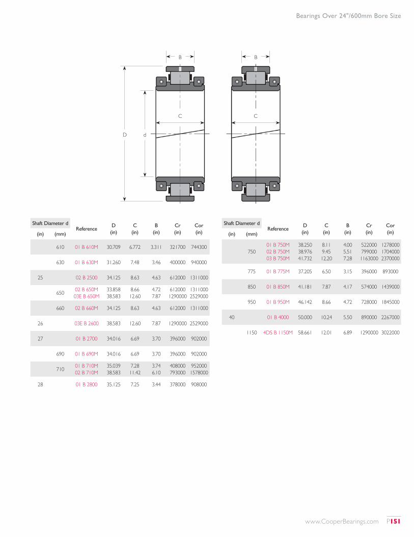
Bearings Over 24"/600mm Bore Size
B B
CC
D d
Shaft Diameter dReference
D (in)
C (in)
B (in)
Cr (in)
Cor (in)(in) (mm)
610 01 B 610M 30.709 6.772 3.311 321700 744300
630 01 B 630M 31.260 7.48 3.46 400000 940000
25 02 B 2500 34.125 8.63 4.63 612000 1311000
650 02 B 650M 03E B 650M
33.858 38.583
8.66 12.60
4.72 7.87
612000 1290000
1311000 2529000
660 02 B 660M 34.125 8.63 4.63 612000 1311000
26 03E B 2600 38.583 12.60 7.87 1290000 2529000
27 01 B 2700 34.016 6.69 3.70 396000 902000
690 01 B 690M 34.016 6.69 3.70 396000 902000
710 01 B 710M 02 B 710M
35.039 38.583
7.28 11.42
3.74 6.10
408000 793000
952000 1578000
28 01 B 2800 35.125 7.25 3.44 378000 908000
Shaft Diameter dReference
D (in)
C (in)
B (in)
Cr (in)
Cor (in)(in) (mm)
75001 B 750M 02 B 750M 03 B 750M
38.250 38.976 41.732
8.11 9.45 12.20
4.00 5.51 7.28
522000 799000 1163000
1278000 1704000 2370000
775 01 B 775M 37.205 6.50 3.15 396000 893000
850 01 B 850M 41.181 7.87 4.17 574000 1439000
950 01 B 950M 46.142 8.66 4.72 728000 1845000
40 01 B 4000 50.000 10.24 5.50 890000 2267000
1150 4DS B 1150M 58.661 12.01 6.89 1290000 3022000
www.CooperBearings.com P151
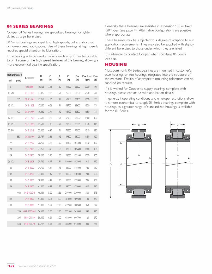
04 Series Bearings
04 SERIES BEARINGSCooper 04 Series bearings are specialized bearings for lighter duties at large bore sizes.04 Series bearings are capable of high speeds, but are also used on lower speed applications. Use of these bearings at high speeds requires special attention to lubrication.If the bearing is to be used at slow speeds only it may be possible to omit some of the ‘high speed’ features of the bearing, allowing a more economical bearing specification.
Generally, these bearings are available in expansion ‘EX’ or fixed ‘GR’ types (see page 4). Alternative configurations are possible where appropriate.These bearings may be subjected to a degree of adaption to suit application requirements. They may also be supplied with slightly different bore sizes to those under which they are listed.It is advisable to contact Cooper when specifying 04 Series bearings.
HOUSINGMost commonly, 04 Series bearings are mounted in customer’s own housings or into housings integrated into the structure of the machine. Details of appropriate mounting tolerances can be supplied on request.If it is wished for Cooper to supply bearings complete with housings, please contact us with application details.In general, if operating conditions and envelope restrictions allow, it is more economical to supply 01 Series bearings complete with housings, as a greater range of standardized housings is available for the 01 Series.
Shaft Diameter dReference
D (in)
C (in)
B (in)
Cr (in)
Cor (in)
Max. Speed (rpm)
Mass (lb)(in) (mm)
6 04 B 600 10.125 3.11 1.50 44500 55300 3000 30
10 5/8 04 B 1010 14.375 4.06 1.91 75500 82500 2470 60
340 04 B 340M 17.250 4.06 1.91 58700 63400 1950 77
13 1/2 04 B 1308 17.250 4.06 1.91 58700 63400 1950 75
400 04 B 400M 19.882 3.94 1.42 48100 52800 1650 75
17 1/2 04 B 1708 21.500 4.25 1.91 67900 82500 1460 100
18 1/2 04 B 1808 22.500 4.25 1.91 71000 88800 1370 110
20 3/4 04 B 2012 25.000 4.49 1.91 73300 95100 1210 120
550 04 B 550M 25.787 3.86 1.42 59800 65000 1150 120
22 04 B 2200 26.250 3.98 1.50 81100 101600 1130 120
23 04 B 2300 27.250 3.98 1.50 82700 105600 1080 130
24 04 B 2400 28.250 3.98 1.50 92800 122100 1020 135
26 1/2 04 B 2608 30.750 4.49 1.91 114400 183900 910 170
30 04 B 3000 34.750 4.49 1.75 83600 114400 780 210
32 04 B 3200 37.000 4.49 1.75 88600 130100 730 230
33 04 B 3300 38.000 4.49 1.75 90600 135300 705 239
36 04 B 3600 41.000 4.49 1.75 94000 125000 620 260
1060 04 B 1060M 48.031 5.00 2.36 214400 330900 560 395
44 04 B 4400 51.000 6.61 3.00 301000 409500 140 440
48 04 B 4800 54.000 5.51 2.75 245900 380500 350 322
1295 04 B 1295AM 56.500 5.00 2.50 222100 361000 340 425
1295 04 B 1295BM 58.000 6.61 3.00 411600 646700 120 690
1550 04 B 1550M 67.717 5.51 2.95 306600 543500 300 741
B B
CC
D d
P152 www.CooperBearings.com
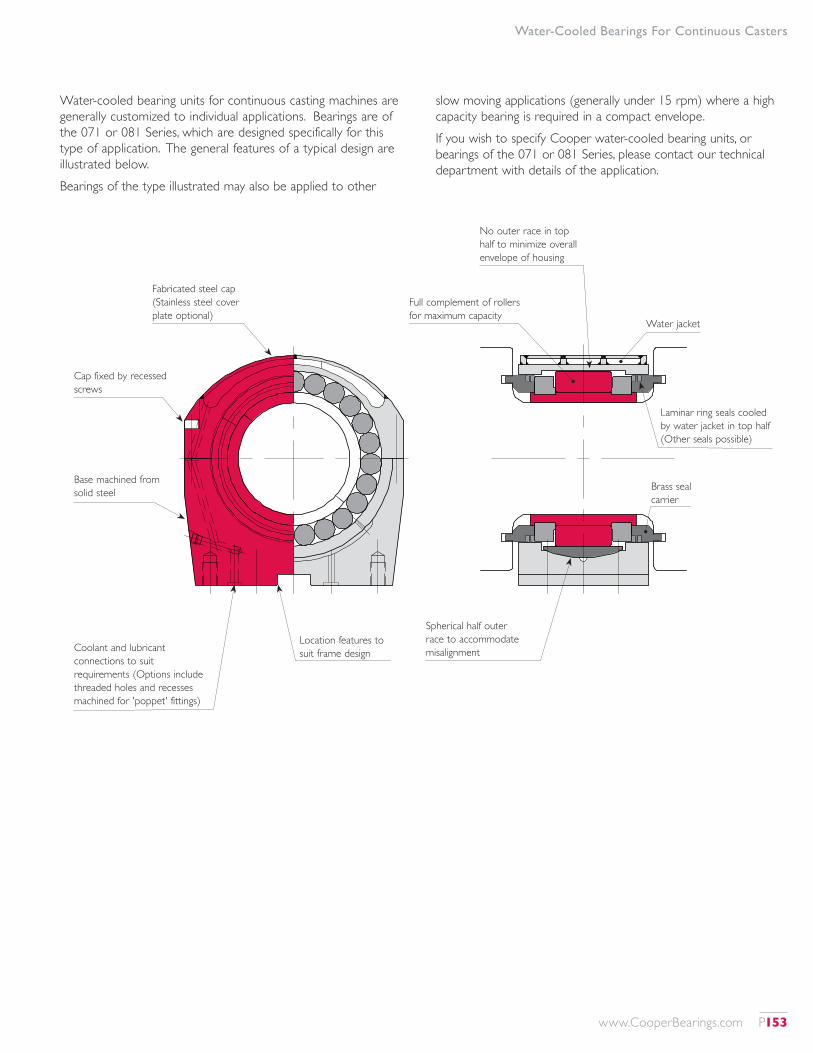
Water-Cooled Bearings For Continuous Casters
Water-cooled bearing units for continuous casting machines are generally customized to individual applications. Bearings are of the 071 or 081 Series, which are designed specifically for this type of application. The general features of a typical design are illustrated below.Bearings of the type illustrated may also be applied to other
slow moving applications (generally under 15 rpm) where a high capacity bearing is required in a compact envelope.If you wish to specify Cooper water-cooled bearing units, or bearings of the 071 or 081 Series, please contact our technical department with details of the application.
Fabricated steel cap (Stainless steel cover plate optional)
No outer race in top half to minimize overall envelope of housing
Laminar ring seals cooled by water jacket in top half (Other seals possible)
Spherical half outer race to accommodate misalignment
Full complement of rollers for maximum capacity
Coolant and lubricant connections to suit requirements (Options include threaded holes and recesses machined for 'poppet' fittings)
Location features to suit frame design
Cap fixed by recessed screws
Water jacket
Brass seal carrier
Base machined from solid steel
www.CooperBearings.com P153
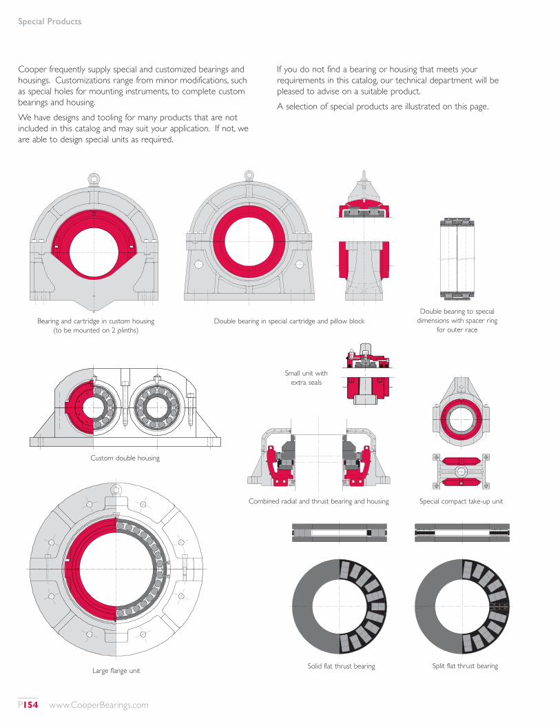
Special Products
Cooper frequently supply special and customized bearings and housings. Customizations range from minor modifications, such as special holes for mounting instruments, to complete custom bearings and housing.We have designs and tooling for many products that are not included in this catalog and may suit your application. If not, we are able to design special units as required.
If you do not find a bearing or housing that meets your requirements in this catalog, our technical department will be pleased to advise on a suitable product.A selection of special products are illustrated on this page.
Bearing and cartridge in custom housing (to be mounted on 2 plinths)
Double bearing in special cartridge and pillow blockDouble bearing to special
dimensions with spacer ring for outer race
Special compact take-up unit
Small unit with extra seals
Combined radial and thrust bearing and housing
Custom double housing
Large flange unit Solid flat thrust bearing Split flat thrust bearing
P154 www.CooperBearings.com
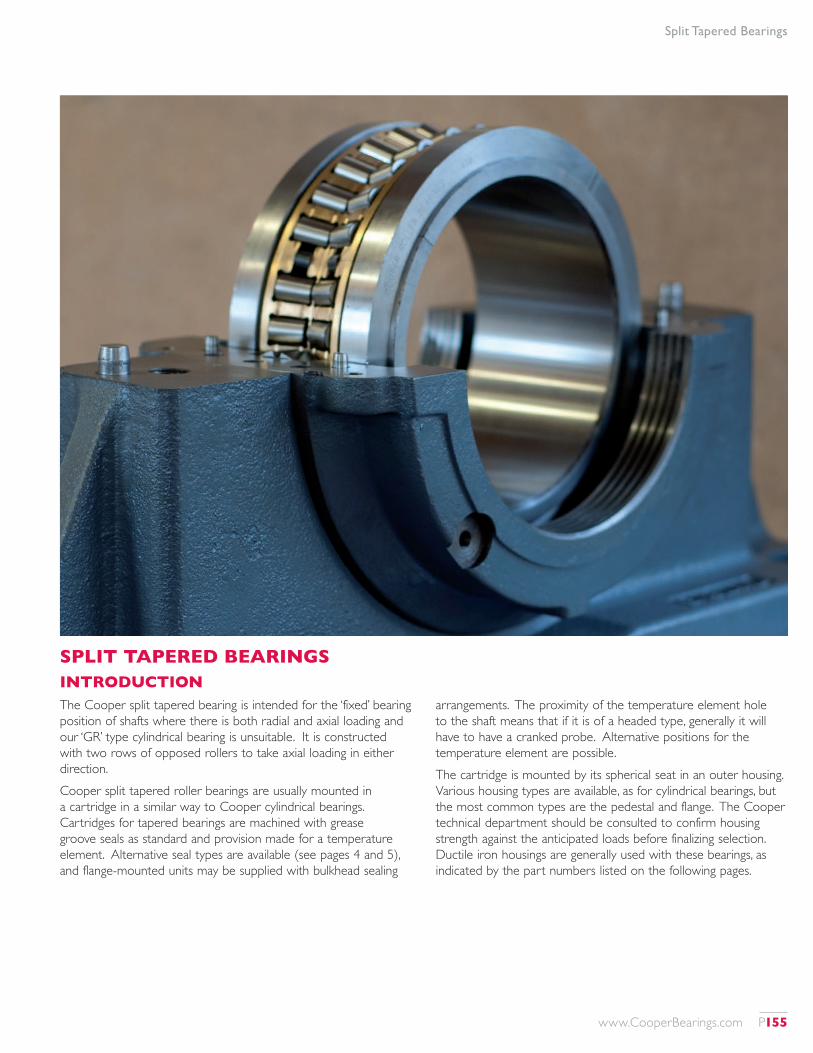
SPLIT TAPERED BEARINGSINTRODUCTIONThe Cooper split tapered bearing is intended for the ‘fixed’ bearing position of shafts where there is both radial and axial loading and our ‘GR’ type cylindrical bearing is unsuitable. It is constructed with two rows of opposed rollers to take axial loading in either direction.Cooper split tapered roller bearings are usually mounted in a cartridge in a similar way to Cooper cylindrical bearings. Cartridges for tapered bearings are machined with grease groove seals as standard and provision made for a temperature element. Alternative seal types are available (see pages 4 and 5), and flange-mounted units may be supplied with bulkhead sealing
arrangements. The proximity of the temperature element hole to the shaft means that if it is of a headed type, generally it will have to have a cranked probe. Alternative positions for the temperature element are possible.The cartridge is mounted by its spherical seat in an outer housing. Various housing types are available, as for cylindrical bearings, but the most common types are the pedestal and flange. The Cooper technical department should be consulted to confirm housing strength against the anticipated loads before finalizing selection. Ductile iron housings are generally used with these bearings, as indicated by the part numbers listed on the following pages.
Split Tapered Bearings
www.CooperBearings.com P155
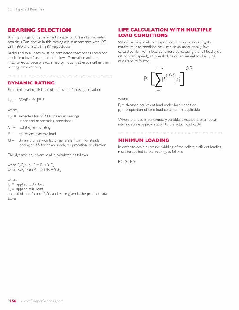
Split Tapered Bearings
BEARING SELECTIONBearing ratings for dynamic radial capacity (Cr) and static radial capacity (Cor) shown in this catalog are in accordance with ISO 281-1990 and ISO 76-1987 respectively.Radial and axial loads must be considered together as combined ‘equivalent loads’, as explained below. Generally, maximum instantaneous loading is governed by housing strength rather than bearing static capacity.
DYNAMIC RATINGExpected bearing life is calculated by the following equation:
L10 = [Cr/(P x fd)](10/3)
where:L10 = expected life of 90% of similar bearings
under similar operating conditionsCr = radial dynamic ratingP = equivalent dynamic loadfd = dynamic or service factor, generally from1 for steady
loading to 3.5 for heavy shock, reciprocation or vibration
The dynamic equivalent load is calculated as follows:
when Fa/Fr ≤ e : P = Fr + Y1Fa when Fa/Fr > e : P = 0.67Fr + Y2Fa
where:Fr = applied radial load Fa = applied axial load and calculation factors Y1, Y2 and e are given in the product data tables.
LIFE CALCULATION WITH MULTIPLE LOAD CONDITIONSWhere varying loads are experienced in operation, using the maximum load condition may lead to an unrealistically low calculated life. For n load conditions constituting the full load cycle (at constant speed), an overall dynamic equivalent load may be calculated as follows:
Pi=n
i=i
Pi pi(10/3)
0.3
where:Pi = dynamic equivalent load under load condition i pi = proportion of time load condition i is applicable
Where the load is continuously variable it may be broken down into a discrete approximation to the actual load cycle.
MINIMUM LOADINGIn order to avoid excessive skidding of the rollers, sufficient loading must be applied to the bearing, as follows:
P ≥ 0.01Cr
P156 www.CooperBearings.com
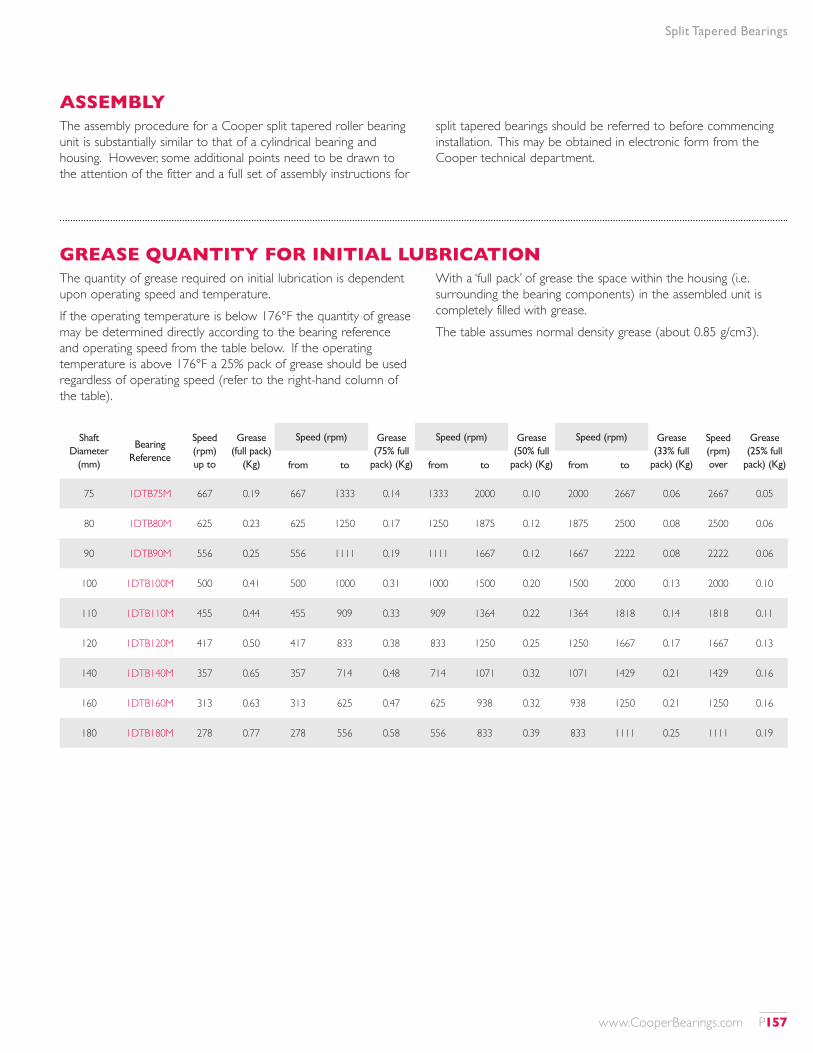
Split Tapered Bearings
Shaft Diameter
(mm)
Bearing Reference
Speed (rpm) up to
Grease (full pack)
(Kg)
Speed (rpm) Grease (75% full
pack) (Kg)
Speed (rpm) Grease (50% full
pack) (Kg)
Speed (rpm) Grease (33% full
pack) (Kg)
Speed (rpm) over
Grease (25% full
pack) (Kg)from to from to from to
75 1DTB75M 667 0.19 667 1333 0.14 1333 2000 0.10 2000 2667 0.06 2667 0.05
80 1DTB80M 625 0.23 625 1250 0.17 1250 1875 0.12 1875 2500 0.08 2500 0.06
90 1DTB90M 556 0.25 556 1111 0.19 1111 1667 0.12 1667 2222 0.08 2222 0.06
100 1DTB100M 500 0.41 500 1000 0.31 1000 1500 0.20 1500 2000 0.13 2000 0.10
110 1DTB110M 455 0.44 455 909 0.33 909 1364 0.22 1364 1818 0.14 1818 0.11
120 1DTB120M 417 0.50 417 833 0.38 833 1250 0.25 1250 1667 0.17 1667 0.13
140 1DTB140M 357 0.65 357 714 0.48 714 1071 0.32 1071 1429 0.21 1429 0.16
160 1DTB160M 313 0.63 313 625 0.47 625 938 0.32 938 1250 0.21 1250 0.16
180 1DTB180M 278 0.77 278 556 0.58 556 833 0.39 833 1111 0.25 1111 0.19
ASSEMBLYThe assembly procedure for a Cooper split tapered roller bearing unit is substantially similar to that of a cylindrical bearing and housing. However, some additional points need to be drawn to the attention of the fitter and a full set of assembly instructions for
split tapered bearings should be referred to before commencing installation. This may be obtained in electronic form from the Cooper technical department.
GREASE QUANTITY FOR INITIAL LUBRICATIONThe quantity of grease required on initial lubrication is dependent upon operating speed and temperature. If the operating temperature is below 176°F the quantity of grease may be determined directly according to the bearing reference and operating speed from the table below. If the operating temperature is above 176°F a 25% pack of grease should be used regardless of operating speed (refer to the right-hand column of the table).
With a ‘full pack’ of grease the space within the housing (i.e. surrounding the bearing components) in the assembled unit is completely filled with grease.The table assumes normal density grease (about 0.85 g/cm3).
www.CooperBearings.com P157
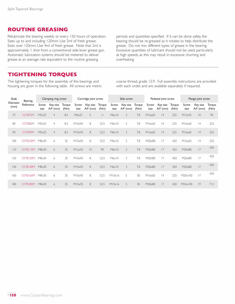
Split Tapered Bearings
Shaft Diameter
(mm)
Bearing Reference
Clamping ring screw Cartridge joint screw Side screw Pedestal joint screw Flange joint screw
Screw size
Key size A/F (mm)
Torque (Nm)
Screw size
Key size A/F (mm)
Torque (Nm)
Screw size
Key size A/F (mm)
Torque (Nm)
Screw size
Key size A/F (mm)
Torque (Nm)
Screw size
Key size A/F (mm)
Torque (Nm)
75 1DTB75M M5x25 4 8.5 M6x25 5 11 M6x10 3 7.8 M16x65 14 225 M12x55 10 90
80 1DTB80M M5x25 4 8.5 M10x45 8 52.5 M6x10 3 7.8 M16x65 14 225 M16x65 14 225
90 1DTB90M M5x25 4 8.5 M10x45 8 52.5 M6x10 3 7.8 M16x65 14 225 M16x65 14 225
100 1DTB100M M8x30 6 35 M10x45 8 52.5 M6x10 3 7.8 M20x80 17 420 M16x65 14 225
110 1DTB110M M8x30 6 35 M12x55 10 90 M6x10 3 7.8 M20x80 17 420 M20x80 17 420
120 1DTB120M M8x30 6 35 M10x45 8 52.5 M6x10 3 7.8 M20x80 17 420 M20x80 17 420
140 1DTB140M M8x30 6 35 M10x45 8 52.5 M6x10 3 7.8 M20x80 17 420 M20x80 17 420
160 1DTB160M M8x30 6 35 M10x45 8 52.5 M10x16 5 30 M16x65 14 225 M20x100 17 420
180 1DTB180M M8x30 6 35 M10x55 8 52.5 M10x16 5 30 M20x80 17 420 M24x100 19 712
ROUTINE GREASINGRelubricate the bearing weekly or every 150 hours of operation. Sizes up to and including 120mm: Use 2ml of fresh grease. Sizes over 120mm: Use 4ml of fresh grease. Note that 2ml is approximately 1 shot from a conventional side-lever grease gun. Automatic lubrication systems should be metered to deliver grease at an average rate equivalent to the routine greasing
periods and quantities specified. If it can be done safely, the bearing should be re-greased as it rotates to help distribute the grease. Do not mix different types of grease in the bearing. Excessive quantities of lubricant should not be used, particularly at high speeds, as this may result in excessive churning and overheating.
TIGHTENING TORQUESThe tightening torques for the assembly of the bearings and housing are given in the following table. All screws are metric
coarse thread, grade 12.9. Full assembly instructions are provided with each order, and are available separately if required.
P158 www.CooperBearings.com
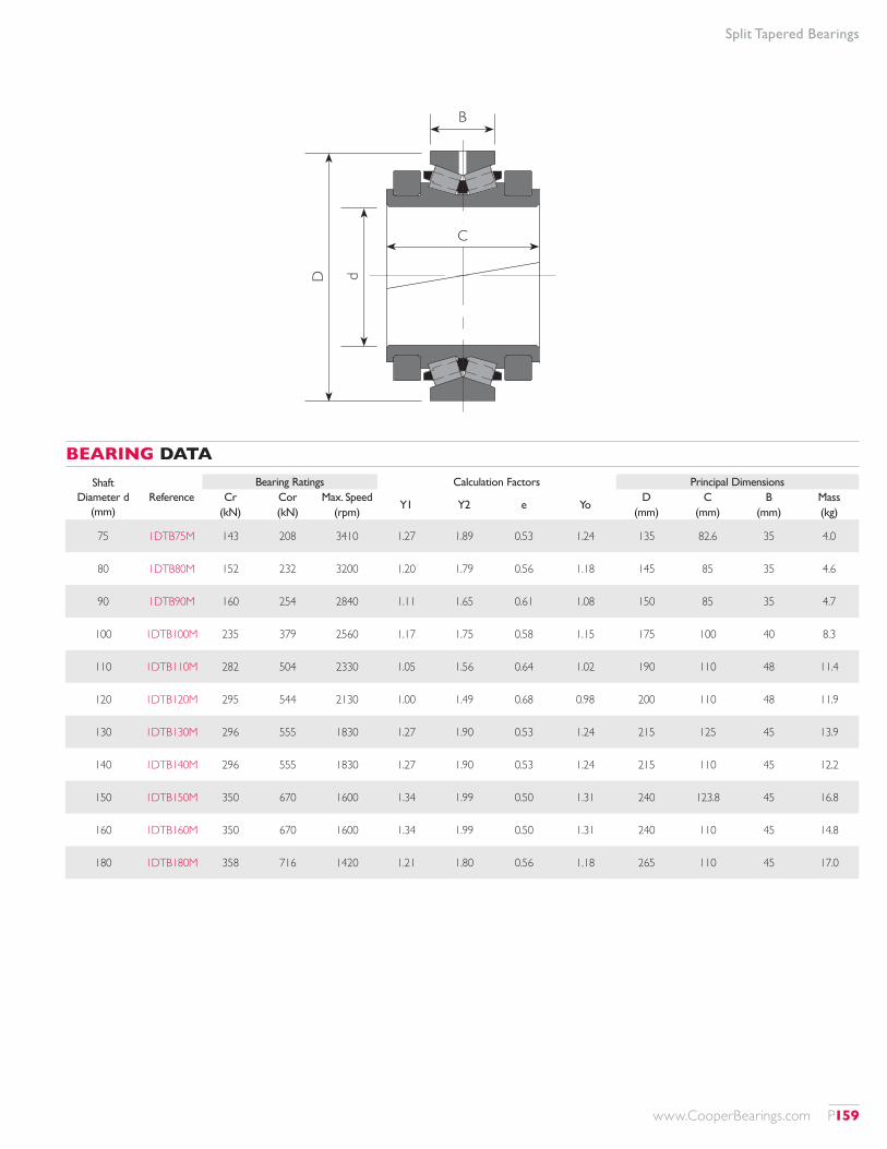
Split Tapered Bearings
Shaft Diameter d
(mm)
Bearing Ratings Calculation Factors Principal DimensionsReference Cr Cor Max. Speed
Y1 Y2 e YoD C B Mass
(kN) (kN) (rpm) (mm) (mm) (mm) (kg)
75 1DTB75M 143 208 3410 1.27 1.89 0.53 1.24 135 82.6 35 4.0
80 1DTB80M 152 232 3200 1.20 1.79 0.56 1.18 145 85 35 4.6
90 1DTB90M 160 254 2840 1.11 1.65 0.61 1.08 150 85 35 4.7
100 1DTB100M 235 379 2560 1.17 1.75 0.58 1.15 175 100 40 8.3
110 1DTB110M 282 504 2330 1.05 1.56 0.64 1.02 190 110 48 11.4
120 1DTB120M 295 544 2130 1.00 1.49 0.68 0.98 200 110 48 11.9
130 1DTB130M 296 555 1830 1.27 1.90 0.53 1.24 215 125 45 13.9
140 1DTB140M 296 555 1830 1.27 1.90 0.53 1.24 215 110 45 12.2
150 1DTB150M 350 670 1600 1.34 1.99 0.50 1.31 240 123.8 45 16.8
160 1DTB160M 350 670 1600 1.34 1.99 0.50 1.31 240 110 45 14.8
180 1DTB180M 358 716 1420 1.21 1.80 0.56 1.18 265 110 45 17.0
BEARING DATA
B
dD
C
www.CooperBearings.com P159
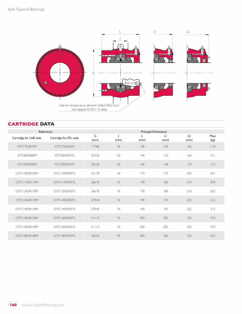
Split Tapered Bearings
References Principal Dimensions
Cartridge for LAB seals Cartridge for ATL sealsG
(mm)J
(mm)L
(mm)L1
(mm)L2
(mm)Mass (kg)
1DTC75GR75M 1DTC75GR30TL 177.80 50 138 140 162 11.8
1DTC80GR80M 1DTC80GR35TL 203.20 50 140 142 164 15.1
1DTC90GR90M 1DTC90GR35TL 203.20 50 146 148 170 13.5
1DTC100GR100M 1DTC100GR40TL 231.78 64 170 172 202 20.1
1DTC110GR110M 1DTC110GR45TL 266.70 76 178 180 210 29.8
1DTC120GR120M 1DTC120GR50TL 266.70 76 178 180 210 26.5
1DTC140GR130M 1DTC140GR50TL 279.40 76 190 192 222 31.2
1DTC140GR140M 1DTC140GR55TL 279.40 76 190 192 222 31.2
1DTC160GR150M 1DTC160GR60TL 311.15 76 200 202 232 47.0
1DTC160GR160M 1DTC160GR65TL 311.15 76 200 202 232 47.0
1DTC180GR180M 1DTC180GR70TL 336.55 95 200 206 232 42.5
CARTRIDGE DATA
L1 L2L
J
G
hole for temperature element drilled Ø6.2 thro' and tapped G1/8 x 12 deep
P160 www.CooperBearings.com
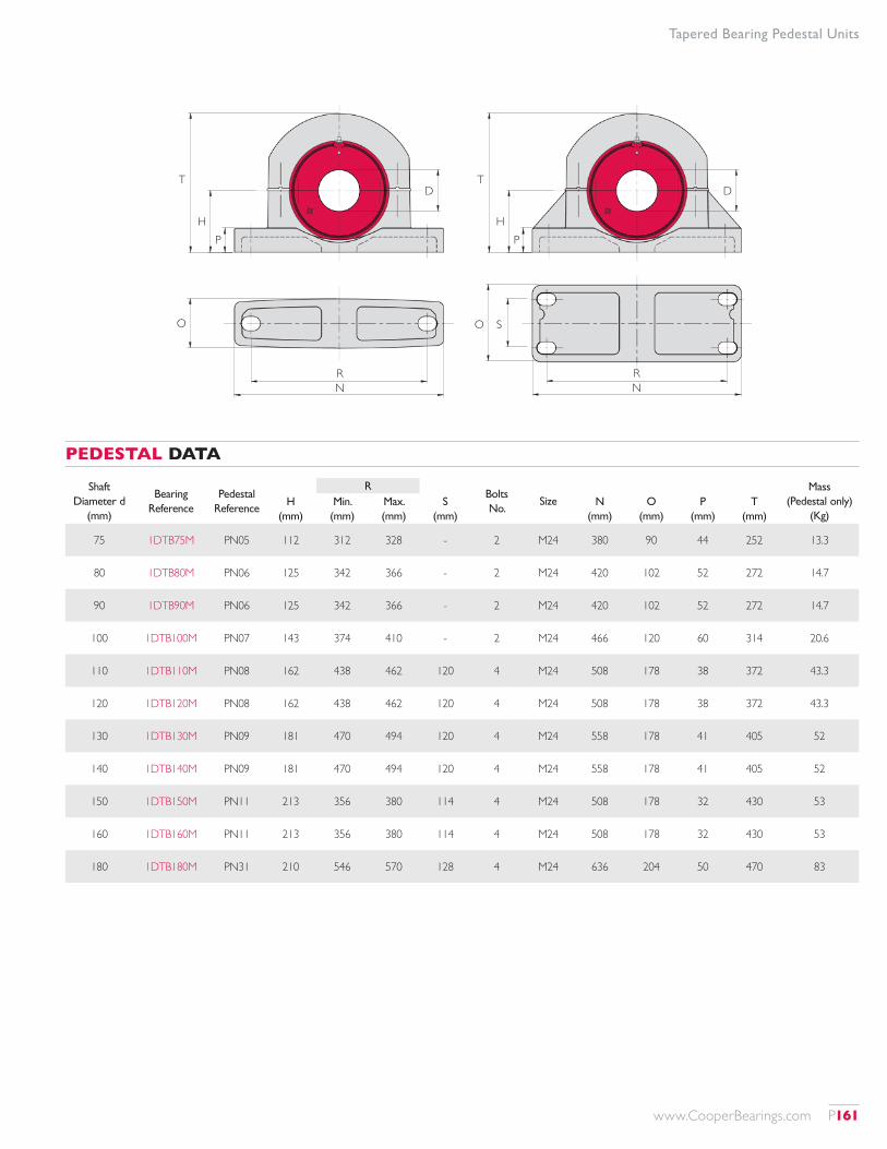
Tapered Bearing Pedestal Units
Shaft Diameter d
(mm)
Bearing Reference
Pedestal Reference
RBolts No.
SizeMass
(Pedestal only) (Kg)
H (mm)
Min. (mm)
Max. (mm)
S (mm)
N (mm)
O (mm)
P (mm)
T (mm)
75 1DTB75M PN05 112 312 328 - 2 M24 380 90 44 252 13.3
80 1DTB80M PN06 125 342 366 - 2 M24 420 102 52 272 14.7
90 1DTB90M PN06 125 342 366 - 2 M24 420 102 52 272 14.7
100 1DTB100M PN07 143 374 410 - 2 M24 466 120 60 314 20.6
110 1DTB110M PN08 162 438 462 120 4 M24 508 178 38 372 43.3
120 1DTB120M PN08 162 438 462 120 4 M24 508 178 38 372 43.3
130 1DTB130M PN09 181 470 494 120 4 M24 558 178 41 405 52
140 1DTB140M PN09 181 470 494 120 4 M24 558 178 41 405 52
150 1DTB150M PN11 213 356 380 114 4 M24 508 178 32 430 53
160 1DTB160M PN11 213 356 380 114 4 M24 508 178 32 430 53
180 1DTB180M PN31 210 546 570 128 4 M24 636 204 50 470 83
PEDESTAL DATA
NN
HH
TT
PP
S
DD
OO
RR
www.CooperBearings.com P161
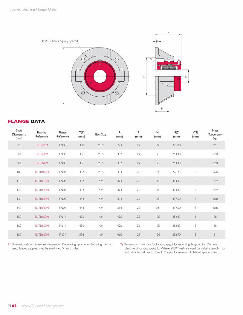
Tapered Bearing Flange Units
Shaft Diameter d
(mm)
Bearing Reference
Flange Reference
T(1) (mm)
Bolt SizeR
(mm)P
(mm)H
(mm)N(2) (mm)
V(2) (mm)
Mass (flange only)
(kg)
75 1DTB75M FN05 330 M16 274 19 79 215.90 3 19.4
80 1DTB80M FN06 356 M16 302 19 86 244.48 3 22.0
90 1DTB90M FN06 356 M16 302 19 86 244.48 3 22.0
100 1DTB100M FN07 382 M16 334 22 92 276.23 3 26.6
110 1DTB110M FN08 432 M24 374 22 98 314.33 3 34.9
120 1DTB120M FN08 432 M24 374 22 98 314.33 3 34.9
130 1DTB130M FN09 444 M24 384 25 98 317.50 3 40.8
140 1DTB140M FN09 444 M24 384 25 98 317.50 3 40.8
150 1DTB150M FN11 496 M24 426 25 105 352.43 3 58
160 1DTB160M FN11 496 M24 426 25 105 352.43 3 58
180 1DTB180M FN31 534 M24 466 25 124 393.70 3 81
FLANGE DATA
1) Dimension shown is as-cast dimension. Depending upon manufacturing method used, flanges supplied may be machined 5mm smaller.
2) Dimensions shown are for locating spigot for mounting flange on to. Diameter tolerance of locating spigot: f8. Where SRSRP seals are used cartridge assembly may protrude into bulkhead. Consult Cooper for minimum bulkhead aperture size.
T N D
H
L
R PCD, holes equally spaced P
V
P162 www.CooperBearings.com
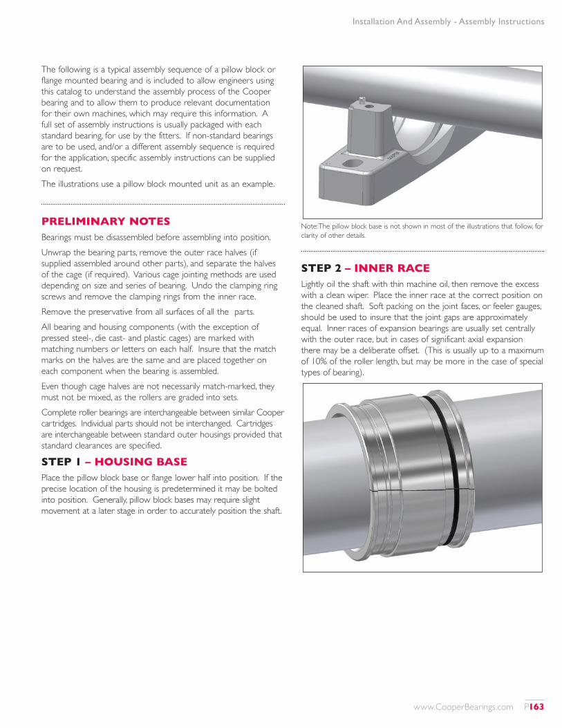
Installation And Assembly - Assembly Instructions
The following is a typical assembly sequence of a pillow block or flange mounted bearing and is included to allow engineers using this catalog to understand the assembly process of the Cooper bearing and to allow them to produce relevant documentation for their own machines, which may require this information. A full set of assembly instructions is usually packaged with each standard bearing, for use by the fitters. If non-standard bearings are to be used, and/or a different assembly sequence is required for the application, specific assembly instructions can be supplied on request.The illustrations use a pillow block mounted unit as an example.
PRELIMINARY NOTESBearings must be disassembled before assembling into position.Unwrap the bearing parts, remove the outer race halves (if supplied assembled around other parts), and separate the halves of the cage (if required). Various cage jointing methods are used depending on size and series of bearing. Undo the clamping ring screws and remove the clamping rings from the inner race.Remove the preservative from all surfaces of all the parts.All bearing and housing components (with the exception of pressed steel-, die cast- and plastic cages) are marked with matching numbers or letters on each half. Insure that the match marks on the halves are the same and are placed together on each component when the bearing is assembled.Even though cage halves are not necessarily match-marked, they must not be mixed, as the rollers are graded into sets.Complete roller bearings are interchangeable between similar Cooper cartridges. Individual parts should not be interchanged. Cartridges are interchangeable between standard outer housings provided that standard clearances are specified.
STEP 1 – HOUSING BASEPlace the pillow block base or flange lower half into position. If the precise location of the housing is predetermined it may be bolted into position. Generally, pillow block bases may require slight movement at a later stage in order to accurately position the shaft.
Note: The pillow block base is not shown in most of the illustrations that follow, for clarity of other details.
STEP 2 – INNER RACELightly oil the shaft with thin machine oil, then remove the excess with a clean wiper. Place the inner race at the correct position on the cleaned shaft. Soft packing on the joint faces, or feeler gauges, should be used to insure that the joint gaps are approximately equal. Inner races of expansion bearings are usually set centrally with the outer race, but in cases of significant axial expansion there may be a deliberate offset. (This is usually up to a maximum of 10% of the roller length, but may be more in the case of special types of bearing).
www.CooperBearings.com P163
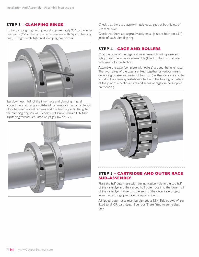
Installation And Assembly - Assembly Instructions
STEP 3 – CLAMPING RINGSFit the clamping rings with joints at approximately 90° to the inner race joints (45° in the case of large bearings with 4-part clamping rings). Progressively tighten all clamping ring screws.
Tap down each half of the inner race and clamping rings all around the shaft using a soft-faced hammer, or insert a hardwood block between a steel hammer and the bearing parts. Retighten the clamping ring screws. Repeat until screws remain fully tight. Tightening torques are listed on pages 167 to 171.
Check that there are approximately equal gaps at both joints of the inner race.Check that there are approximately equal joints at both (or all 4) joints of each clamping ring.
STEP 4 – CAGE AND ROLLERSCoat the bore of the cage and roller assembly with grease and lightly cover the inner race assembly (fitted to the shaft) all over with grease for protection.Assemble the cage (complete with rollers) around the inner race. The two halves of the cage are fixed together by various means depending on size and series of bearing. (Further details are to be found in the assembly leaflets supplied with the bearing, or details of the joint of a particular size and series of cage can be supplied on request.)
STEP 5 – CARTRIDGE AND OUTER RACE SUB-ASSEMBLYPlace the half outer race with the lubrication hole in the top half of the cartridge and the second half outer race into the lower half of the cartridge. Insure that the ends of the outer race project from the cartridge joint face by equal amounts.All lipped outer races must be clamped axially. Side screws ‘A’ are fitted to all GR cartridges. Side rods ‘B’ are fitted to some sizes only.
P164 www.CooperBearings.com
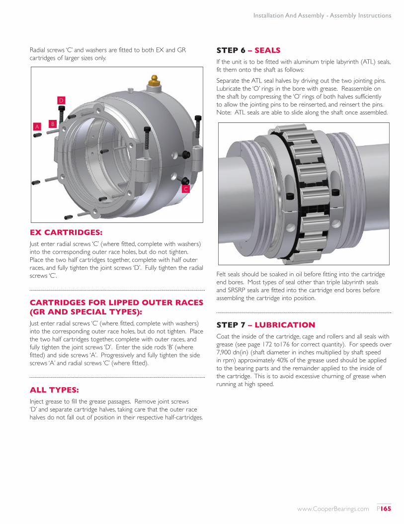
Installation And Assembly - Assembly Instructions
Radial screws ‘C’ and washers are fitted to both EX and GR cartridges of larger sizes only.
A B
D
C
EX CARTRIDGES:Just enter radial screws ‘C’ (where fitted, complete with washers) into the corresponding outer race holes, but do not tighten. Place the two half cartridges together, complete with half outer races, and fully tighten the joint screws ‘D’. Fully tighten the radial screws ‘C’.
CARTRIDGES FOR LIPPED OUTER RACES (GR AND SPECIAL TYPES):Just enter radial screws ‘C’ (where fitted, complete with washers) into the corresponding outer race holes, but do not tighten. Place the two half cartridges together, complete with outer races, and fully tighten the joint screws ‘D’. Enter the side rods ‘B’ (where fitted) and side screws ‘A’. Progressively and fully tighten the side screws ‘A’ and radial screws ‘C’ (where fitted).
ALL TYPES:Inject grease to fill the grease passages. Remove joint screws ‘D’ and separate cartridge halves, taking care that the outer race halves do not fall out of position in their respective half-cartridges.
STEP 6 – SEALSIf the unit is to be fitted with aluminum triple labyrinth (ATL) seals, fit them onto the shaft as follows:Separate the ATL seal halves by driving out the two jointing pins. Lubricate the ‘O’ rings in the bore with grease. Reassemble on the shaft by compressing the ‘O’ rings of both halves sufficiently to allow the jointing pins to be reinserted, and reinsert the pins. Note: ATL seals are able to slide along the shaft once assembled.
Felt seals should be soaked in oil before fitting into the cartridge end bores. Most types of seal other than triple labyrinth seals and SRSRP seals are fitted into the cartridge end bores before assembling the cartridge into position.
STEP 7 – LUBRICATIONCoat the inside of the cartridge, cage and rollers and all seals with grease (see page 172 to176 for correct quantity). For speeds over 7,900 dn(in) (shaft diameter in inches multiplied by shaft speed in rpm) approximately 40% of the grease used should be applied to the bearing parts and the remainder applied to the inside of the cartridge. This is to avoid excessive churning of grease when running at high speed.
www.CooperBearings.com P165

Installation And Assembly - Assembly Instructions
STEP 8 – CARTRIDGELubricate the spherical seating of the bottom half of the cartridge with grease.Place the bottom half of the cartridge on top of the bearing and rotate 180° into the pillow block base or half-flange.Place the top half of the cartridge on top of the bottom half, close the cartridge and fully tighten the joint screws. Lubricate the spherical seating with grease.
STEP 9 – HOUSINGIf not already done, tighten the bolts fixing the pillow block base or lower flange half into position.Place the pillow block cap or flange top half into position. If it is safe to do so, running the shaft for a time without the outer housing joint screws fully tightened will help the bearing to accurately align.Fully tighten the joint screws.
P166 www.CooperBearings.com
Installation And Assembly - Screw Sizes, Wrench Sizes And Torques
Shaft Diameter
d (in)
Bearing Reference
Clamping Ring Screw (1) Cartridge Joint Screw (1) Cartridge Radial Screw (1) Side Screw (1) Pillow Block Joint Screw (1) Flange Joint Screw (1)
Screw Size
Key Size A/F (mm)
Torque(2) (lb ft)
Screw Size
Key Size A/F (mm)
Torque (lb ft)
Screw Size
Key Size A/F (mm)
Torque (lb ft)
Screw Size
Key Size A/F (mm)
Torque (lb ft)
Screw Size
Key Size A/F (mm)
Torque (lb ft)
Screw Size
Key Size A/F (mm)
Torque (lb ft)
1 3/16 01 B 103 M4x20 3 3.3 M4x25 3 2.6 - - - M4x10 2 1.5 M8x45 6 19 M8x40 6 19
1 1/4 01 B 104 M4x20 3 3.3 M4x25 3 2.6 - - - M4x10 2 1.5 M8x45 6 19 M8x40 6 19
1 7/16 01 B 107 M4x20 3 3.3 M4x25 3 2.6 - - - M4x10 2 1.5 M8x45 6 19 M8x40 6 19
1 1/2 01 B 108 M4x20 3 3.3 M4x25 3 2.6 - - - M4x10 2 1.5 M8x45 6 19 M8x40 6 19
1 11/16 01E B 111 M4x20 3 3.3 M4x25 3 2.6 - - - M4x10 2 1.5 M8x45 6 19 M8x40 6 19
1 3/4 01E B 112 M4x20 3 3.3 M4x25 3 2.6 - - - M4x10 2 1.5 M8x45 6 19 M8x40 6 19
1 15/16 01E B 115 02 B 115
M4x20 M5x25
3 4
3.3 6.3
M4x25 M5x25
3 4
2.6 4.8
- -
- -
- -
M4x10 M4x10
2 2
1.5 1.5
M8x45 M10x55
6 8
19 39
M8x40 M10x45
6 8
19 39
2 01E B 200 02 B 200
M4x20 M5x25
3 4
3.3 6.3
M4x25 M5x25
3 4
2.6 4.8
- -
- -
- -
M4x10 M4x10
2 2
1.5 1.5
M8x45 M10x55
6 8
19 39
M8x40 M10x45
6 8
19 39
2 3/16 01E B 203 02 B 203
M4x20 M5x25
3 4
3.3 6.3
M4x25 M5x25
3 4
2.6 4.8
- -
- -
- -
M4x10 M4x10
2 2
1.5 1.5
M10x55 M12x65
8 10
39 66
M10x45 M12x55
8 10
39 66
2 1/4 01E B 204 02 B 204
M4x20 M5x25
3 4
3.3 6.3
M4x25 M5x25
3 4
2.6 4.8
- -
- -
- -
M4x10 M4x10
2 2
1.5 1.5
M10x55 M12x65
8 10
39 66
M10x45 M12x55
8 10
39 66
2 7/16 01E B 207 02 B 207
M4x20 M5x25
3 4
3.3 6.3
M4x25 M5x25
3 4
2.6 4.8
- -
- -
- -
M4x10 M4x10
2 2
1.5 1.5
M10x55 M12x65
8 10
39 66
M10x45 M12x55
8 10
39 66
2 1/2 01E B 208 02 B 208
M4x20 M5x25
3 4
3.3 6.3
M4x25 M5x25
3 4
2.6 4.8
- -
- -
- -
M4x10 M4x10
2 2
1.5 1.5
M10x55 M12x65
8 10
39 66
M10x45 M12x55
8 10
39 66
2 11/16 01E B 211 02 B 211
M4x20 M6x25
3 5
3.3 11
M4x25 M6x25
3 5
2.6 8.1
- -
- -
- -
M4x10 M4x10
2 2
1.5 1.5
M12x65 M16x65
10 14
66 166
M12x55 M12x55
10 10
66 66
2 3/4 01E B 212 02 B 212
M4x20 M6x25
3 5
3.3 11
M4x25 M6x25
3 5
2.6 8.1
- -
- -
- -
M4x10 M4x10
2 2
1.5 1.5
M12x65 M16x65
10 14
66 166
M12x55 M12x55
10 10
66 66
2 15/16100 B 215 01E B 215 02 B 215
M3x16 M4x20 M6x25
2.5 3 5
1.5 3.3 11
M4x25 M4x25 M6x25
3 3 5
2.6 2.6 8.1
- - -
- - -
- - -
M4x10 M4x10 M4x10
2 2 2
1.5 1.5 1.5
M10x55 M12x65 M16x65
8 10 14
39 66 166
M10x45 M12x55 M12x55
8 10 10
39 66 66
1) All screws are metric coarse thread, grade 12.9
2) For vertical shaft or high thrust applications the clamping ring screw torque should be increased by up to 20%
www.CooperBearings.com P167
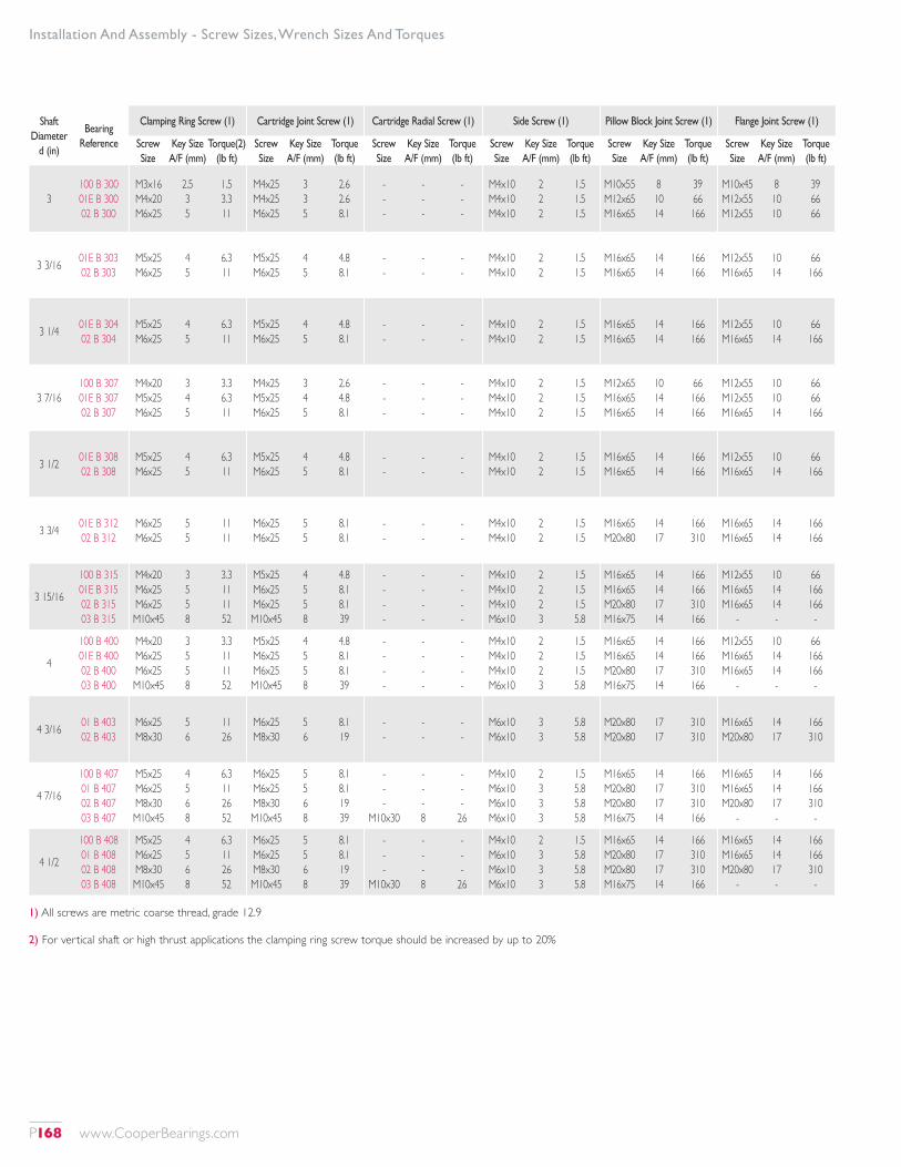
Shaft Diameter
d (in)
Bearing Reference
Clamping Ring Screw (1) Cartridge Joint Screw (1) Cartridge Radial Screw (1) Side Screw (1) Pillow Block Joint Screw (1) Flange Joint Screw (1)
Screw Size
Key Size A/F (mm)
Torque(2) (lb ft)
Screw Size
Key Size A/F (mm)
Torque (lb ft)
Screw Size
Key Size A/F (mm)
Torque (lb ft)
Screw Size
Key Size A/F (mm)
Torque (lb ft)
Screw Size
Key Size A/F (mm)
Torque (lb ft)
Screw Size
Key Size A/F (mm)
Torque (lb ft)
3100 B 300 01E B 300 02 B 300
M3x16 M4x20 M6x25
2.5 3 5
1.5 3.3 11
M4x25 M4x25 M6x25
3 3 5
2.6 2.6 8.1
- - -
- - -
- - -
M4x10 M4x10 M4x10
2 2 2
1.5 1.5 1.5
M10x55 M12x65 M16x65
8 10 14
39 66 166
M10x45 M12x55 M12x55
8 10 10
39 66 66
3 3/16 01E B 303 02 B 303
M5x25 M6x25
4 5
6.3 11
M5x25 M6x25
4 5
4.8 8.1
- -
- -
- -
M4x10 M4x10
2 2
1.5 1.5
M16x65 M16x65
14 14
166 166
M12x55 M16x65
10 14
66 166
3 1/4 01E B 304 02 B 304
M5x25 M6x25
4 5
6.3 11
M5x25 M6x25
4 5
4.8 8.1
- -
- -
- -
M4x10 M4x10
2 2
1.5 1.5
M16x65 M16x65
14 14
166 166
M12x55 M16x65
10 14
66 166
3 7/16100 B 307 01E B 307 02 B 307
M4x20 M5x25 M6x25
3 4 5
3.3 6.3 11
M4x25 M5x25 M6x25
3 4 5
2.6 4.8 8.1
- - -
- - -
- - -
M4x10 M4x10 M4x10
2 2 2
1.5 1.5 1.5
M12x65 M16x65 M16x65
10 14 14
66 166 166
M12x55 M12x55 M16x65
10 10 14
66 66 166
3 1/2 01E B 308 02 B 308
M5x25 M6x25
4 5
6.3 11
M5x25 M6x25
4 5
4.8 8.1
- -
- -
- -
M4x10 M4x10
2 2
1.5 1.5
M16x65 M16x65
14 14
166 166
M12x55 M16x65
10 14
66 166
3 3/4 01E B 312 02 B 312
M6x25 M6x25
5 5
11 11
M6x25 M6x25
5 5
8.1 8.1
- -
- -
- -
M4x10 M4x10
2 2
1.5 1.5
M16x65 M20x80
14 17
166 310
M16x65 M16x65
14 14
166 166
3 15/16
100 B 315 01E B 315 02 B 315 03 B 315
M4x20 M6x25 M6x25 M10x45
3 5 5 8
3.3 11 11 52
M5x25 M6x25 M6x25 M10x45
4 5 5 8
4.8 8.1 8.1 39
- - - -
- - - -
- - - -
M4x10 M4x10 M4x10 M6x10
2 2 2 3
1.5 1.5 1.5 5.8
M16x65 M16x65 M20x80 M16x75
14 14 17 14
166 166 310 166
M12x55 M16x65 M16x65
-
10 14 14 -
66 166 166
-
4
100 B 400 01E B 400 02 B 400 03 B 400
M4x20 M6x25 M6x25 M10x45
3 5 5 8
3.3 11 11 52
M5x25 M6x25 M6x25 M10x45
4 5 5 8
4.8 8.1 8.1 39
- - - -
- - - -
- - - -
M4x10 M4x10 M4x10 M6x10
2 2 2 3
1.5 1.5 1.5 5.8
M16x65 M16x65 M20x80 M16x75
14 14 17 14
166 166 310 166
M12x55 M16x65 M16x65
-
10 14 14 -
66 166 166
-
4 3/16 01 B 403 02 B 403
M6x25 M8x30
5 6
11 26
M6x25 M8x30
5 6
8.1 19
- -
- -
- -
M6x10 M6x10
3 3
5.8 5.8
M20x80 M20x80
17 17
310 310
M16x65 M20x80
14 17
166 310
4 7/16
100 B 407 01 B 407 02 B 407 03 B 407
M5x25 M6x25 M8x30 M10x45
4 5 6 8
6.3 11 26 52
M6x25 M6x25 M8x30 M10x45
5 5 6 8
8.1 8.1 19 39
- - -
M10x30
- - - 8
- - -
26
M4x10 M6x10 M6x10 M6x10
2 3 3 3
1.5 5.8 5.8 5.8
M16x65 M20x80 M20x80 M16x75
14 17 17 14
166 310 310 166
M16x65 M16x65 M20x80
-
14 14 17 -
166 166 310
-
4 1/2
100 B 408 01 B 408 02 B 408 03 B 408
M5x25 M6x25 M8x30 M10x45
4 5 6 8
6.3 11 26 52
M6x25 M6x25 M8x30 M10x45
5 5 6 8
8.1 8.1 19 39
- - -
M10x30
- - - 8
- - -
26
M4x10 M6x10 M6x10 M6x10
2 3 3 3
1.5 5.8 5.8 5.8
M16x65 M20x80 M20x80 M16x75
14 17 17 14
166 310 310 166
M16x65 M16x65 M20x80
-
14 14 17 -
166 166 310
-
Installation And Assembly - Screw Sizes, Wrench Sizes And Torques
1) All screws are metric coarse thread, grade 12.9
2) For vertical shaft or high thrust applications the clamping ring screw torque should be increased by up to 20%
P168 www.CooperBearings.com
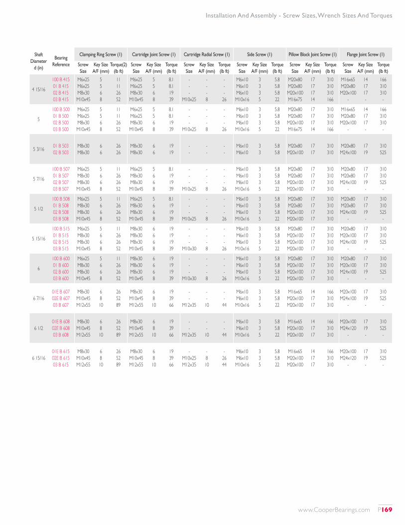
Shaft Diameter
d (in)
Bearing Reference
Clamping Ring Screw (1) Cartridge Joint Screw (1) Cartridge Radial Screw (1) Side Screw (1) Pillow Block Joint Screw (1) Flange Joint Screw (1)
Screw Size
Key Size A/F (mm)
Torque(2) (lb ft)
Screw Size
Key Size A/F (mm)
Torque (lb ft)
Screw Size
Key Size A/F (mm)
Torque (lb ft)
Screw Size
Key Size A/F (mm)
Torque (lb ft)
Screw Size
Key Size A/F (mm)
Torque (lb ft)
Screw Size
Key Size A/F (mm)
Torque (lb ft)
4 15/16
100 B 415 01 B 415 02 B 415 03 B 415
M6x25 M6x25 M8x30 M10x45
5 5 6 8
11 11 26 52
M6x25 M6x25 M8x30 M10x45
5 5 6 8
8.1 8.1 19 39
- - -
M10x25
- - - 8
- - -
26
M6x10 M6x10 M6x10 M10x16
3 3 3 5
5.8 5.8 5.8 22
M20x80 M20x80 M20x100 M16x75
17 17 17 14
310 310 310 166
M16x65 M20x80 M20x100
-
14 17 17 -
166 310 310
-
5
100 B 500 01 B 500 02 B 500 03 B 500
M6x25 M6x25 M8x30 M10x45
5 5 6 8
11 11 26 52
M6x25 M6x25 M8x30 M10x45
5 5 6 8
8.1 8.1 19 39
- - -
M10x25
- - - 8
- - -
26
M6x10 M6x10 M6x10 M10x16
3 3 3 5
5.8 5.8 5.8 22
M20x80 M20x80 M20x100 M16x75
17 17 17 14
310 310 310 166
M16x65 M20x80 M20x100
-
14 17 17 -
166 310 310
-
5 3/16 01 B 503 02 B 503
M8x30 M8x30
6 6
26 26
M8x30 M8x30
6 6
19 19
- -
- -
- -
M6x10 M6x10
3 3
5.8 5.8
M20x80 M20x100
17 17
310 310
M20x80 M24x100
17 19
310 525
5 7/16
100 B 507 01 B 507 02 B 507 03 B 507
M6x25 M8x30 M8x30 M10x45
5 6 6 8
11 26 26 52
M6x25 M8x30 M8x30 M10x45
5 6 6 8
8.1 19 19 39
- - -
M10x25
- - - 8
- - -
26
M6x10 M6x10 M6x10 M10x16
3 3 3 5
5.8 5.8 5.8 22
M20x80 M20x80 M20x100 M20x100
17 17 17 17
310 310 310 310
M20x80 M20x80 M24x100
-
17 17 19 -
310 310 525
-
5 1/2
100 B 508 01 B 508 02 B 508 03 B 508
M6x25 M8x30 M8x30 M10x45
5 6 6 8
11 26 26 52
M6x25 M8x30 M8x30 M10x45
5 6 6 8
8.1 19 19 39
- - -
M10x25
- - - 8
- - -
26
M6x10 M6x10 M6x10 M10x16
3 3 3 5
5.8 5.8 5.8 22
M20x80 M20x80 M20x100 M20x100
17 17 17 17
310 310 310 310
M20x80 M20x80 M24x100
-
17 17 19 -
310 310 525
-
5 15/16
100 B 515 01 B 515 02 B 515 03 B 515
M6x25 M8x30 M8x30 M10x45
5 6 6 8
11 26 26 52
M8x30 M8x30 M8x30 M10x45
6 6 6 8
19 19 19 39
- - -
M10x30
- - - 8
- - -
26
M6x10 M6x10 M6x10 M10x16
3 3 3 5
5.8 5.8 5.8 22
M20x80 M20x100 M20x100 M20x100
17 17 17 17
310 310 310 310
M20x80 M20x100 M24x100
-
17 17 19 -
310 310 525
-
6
100 B 600 01 B 600 02 B 600 03 B 600
M6x25 M8x30 M8x30 M10x45
5 6 6 8
11 26 26 52
M8x30 M8x30 M8x30 M10x45
6 6 6 8
19 19 19 39
- - -
M10x30
- - - 8
- - -
26
M6x10 M6x10 M6x10 M10x16
3 3 3 5
5.8 5.8 5.8 22
M20x80 M20x100 M20x100 M20x100
17 17 17 17
310 310 310 310
M20x80 M20x100 M24x100
-
17 17 19 -
310 310 525
-
6 7/1601E B 607 02E B 607 03 B 607
M8x30 M10x45 M12x55
6 8 10
26 52 89
M8x30 M10x45 M12x55
6 8 10
19 39 66
- -
M12x35
- -
10
- -
44
M6x10 M6x10 M10x16
3 3 5
5.8 5.8 22
M16x65 M20x100 M20x100
14 17 17
166 310 310
M20x100 M24x100
-
17 19 -
310 525
-
6 1/201E B 608 02E B 608 03 B 608
M8x30 M10x45 M12x55
6 8 10
26 52 89
M8x30 M10x45 M12x55
6 8 10
19 39 66
- -
M12x35
- -
10
- -
44
M6x10 M6x10 M10x16
3 3 5
5.8 5.8 22
M16x65 M20x100 M20x100
14 17 17
166 310 310
M20x100 M24x120
-
17 19 -
310 525
-
6 15/1601E B 615 02E B 615 03 B 615
M8x30 M10x45 M12x55
6 8 10
26 52 89
M8x30 M10x45 M12x55
6 8 10
19 39 66
- M10x25 M12x35
- 8 10
- 26 44
M6x10 M6x10 M10x16
3 3 5
5.8 5.8 22
M16x65 M20x100 M20x100
14 17 17
166 310 310
M20x100 M24x120
-
17 19 -
310 525
-
Installation And Assembly - Screw Sizes, Wrench Sizes And Torques
www.CooperBearings.com P169
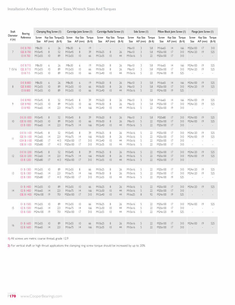
Shaft Diameter
d (in)
Bearing Reference
Clamping Ring Screw (1) Cartridge Joint Screw (1) Cartridge Radial Screw (1) Side Screw (1) Pillow Block Joint Screw (1) Flange Joint Screw (1)
Screw Size
Key Size A/F (mm)
Torque(2) (lb ft)
Screw Size
Key Size A/F (mm)
Torque (lb ft)
Screw Size
Key Size A/F (mm)
Torque (lb ft)
Screw Size
Key Size A/F (mm)
Torque (lb ft)
Screw Size
Key Size A/F (mm)
Torque (lb ft)
Screw Size
Key Size A/F (mm)
Torque (lb ft)
701E B 700 02E B 700 03 B 700
M8x30 M10x45 M12x55
6 8 10
26 52 89
M8x30 M10x45 M12x55
6 8 10
19 39 66
- M10x25 M12x35
- 8 10
- 26 44
M6x10 M6x10 M10x16
3 3 5
5.8 5.8 22
M16x65 M20x100 M20x100
14 17 17
166 310 310
M20x100 M24x120
-
17 19 -
310 525
-
7 15/1601E B 715 02E B 715 03 B 715
M8x30 M12x55 M12x55
6 10 10
26 89 89
M8x30 M12x55 M12x55
6 10 10
19 66 66
M10x20 M10x30 M12x40
8 8 10
26 26 44
M6x10 M6x10 M10x16
3 3 5
5.8 5.8 22
M16x65 M20x100 M24x100
14 17 19
166 310 525
M24x100 M24x120
-
19 19 -
525 525
-
801E B 800 02E B 800 03 B 800
M8x30 M12x55 M12x55
6 10 10
26 89 89
M8x30 M12x55 M12x55
6 10 10
19 66 66
M10x20 M10x30 M12x40
8 8 10
26 26 44
M6x10 M6x10 M10x16
3 3 5
5.8 5.8 22
M16x65 M20x100 M24x100
14 17 19
166 310 525
M24x100 M24x120
-
19 19 -
525 525
-
901E B 900 02E B 900 03 B 900
M10x45 M12x55 M16x65
8 10 14
52 89 221
M10x45 M12x55 M16x75
8 10 14
39 66 166
M10x20 M10x30 M12x40
8 8 10
26 26 44
M6x10 M6x10 M10x16
3 3 5
5.8 5.8 22
M16x65 M20x100 M20x100
14 17 19
166 310 310
M24x100 M24x120
-
19 19 -
525 525
-
1001E B 1000 02E B 1000 03 B 1000
M10x45 M12x55 M16x65
8 10 14
52 89 221
M10x45 M12x55 M16x75
8 10 14
39 66 166
M10x20 M10x30 M12x40
8 8 10
26 26 44
M6x10 M6x10 M10x16
3 5 5
5.8 22 22
M20x80 M20x100 M20x100
17 17 17
310 310 310
M24x100 M24x100
-
19 19 -
525 525
-
11
01E B 1100 02E B 1100 03X B 1100 03E B 1100
M10x45 M12x65 M20x80 M20x80
8 14 17 17
52 221 413 413
M10x45 M16x75 M20x100 M20x100
8 14 17 17
39 166 310 310
M10x25 M10x30 M12x40 M12x35
8 8 10 10
26 26 44 44
M10x16 M10x16 M10x16 M10x16
5 5 5 5
22 22 22 22
M20x100 M20x100 M20x100 M20x100
17 17 17 17
310 310 310 310
M24x120 M24x100
- -
19 19 - -
525 525
- -
1201E B 1200 02E B 1200 03 B 1200
M10x45 M12x65 M20x80
8 14 17
52 221 413
M10x45 M16x75 M20x100
8 14 17
39 166 310
M10x25 M10x30 M12x55
8 8 10
26 26 44
M10x16 M10x16 M10x16
5 5 5
22 22 22
M20x100 M20x100 M20x100
17 17 17
310 310 310
M24x120 M24x100
-
19 19 -
525 525
-
1301 B 1300 02 B 1300 03 B 1300
M12x55 M16x65 M20x80
10 14 17
89 221 413
M12x55 M16x75 M20x100
8 14 17
66 166 310
M10x25 M10x30 M12x55
8 8 10
26 26 44
M10x16 M10x16 M10x16
5 5 5
22 22 22
M20x100 M20x100 M24x100
17 17 19
310 310 525
M24x120 M24x120
-
19 19 -
525 525
-
1401 B 1400 02 B 1400 03E B 1400
M12x55 M16x65 M24x100
10 14 19
89 221 701
M12x55 M16x75 M20x100
10 14 17
66 166 310
M10x25 M12x30 M12x40
8 10 10
26 44 44
M10x16 M10x16 M16x25
5 5 8
22 22 92
M20x100 M20x100 M24x100
17 17 19
310 310 525
M24x120 - -
19 - -
525 - -
1501 B 1500 02 B 1500 03 B 1500
M12x55 M16x65 M24x100
10 14 19
89 221 701
M12x55 M16x75 M20x100
10 14 17
66 166 310
M10x25 M12x30 M12x55
8 10 10
26 44 44
M10x16 M10x16 M10x16
5 5 5
22 22 22
M20x100 M20x100 M24x120
17 17 19
310 310 525
M24x100 - -
19 - -
525 - -
16 01 B 1600 02 B 1600
M12x55 M16x65
10 14
89 221
M12x55 M16x75
10 14
66 166
M10x25 M12x35
8 10
26 44
M10x16 M10x16
5 5
22 22
M20x100 M20x100
17 17
310 310
M24x100 -
19 -
525 -
Installation And Assembly - Screw Sizes, Wrench Sizes And Torques
1) All screws are metric coarse thread, grade 12.9
2) For vertical shaft or high thrust applications the clamping ring screw torque should be increased by up to 20%
P170 www.CooperBearings.com
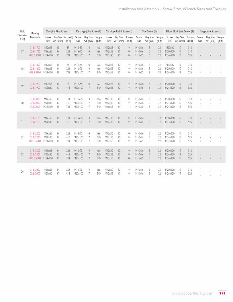
Shaft Diameter
d (in)
Bearing Reference
Clamping Ring Screw (1) Cartridge Joint Screw (1) Cartridge Radial Screw (1) Side Screw (1) Pillow Block Joint Screw (1) Flange Joint Screw (1)
Screw Size
Key Size A/F (mm)
Torque(2) (lb ft)
Screw Size
Key Size A/F (mm)
Torque (lb ft)
Screw Size
Key Size A/F (mm)
Torque (lb ft)
Screw Size
Key Size A/F (mm)
Torque (lb ft)
Screw Size
Key Size A/F (mm)
Torque (lb ft)
Screw Size
Key Size A/F (mm)
Torque (lb ft)
1701 B 1700 02 B 1700 03E B 1700
M12x55 M16x65 M24x100
10 14 19
89 221 701
M12x55 M16x75 M20x100
10 14 17
66 166 310
M12x25 M12x35 M12x40
10 10 10
44 44 44
M10x16 M10x16 M16x25
5 5 8
22 22 92
M20x80 M20x100 M24x120
17 17 19
310 310 525
- - -
- - -
- - -
1801 B 1800 02 B 1800 03E B 1800
M12x55 M16x65 M24x100
10 14 19
89 221 701
M12x55 M16x75 M20x100
10 14 17
66 166 310
M12x25 M12x35 M12x55
10 10 10
44 44 44
M10x16 M10x16 M16x25
5 5 8
22 22 92
M20x80 M20x100 M24x120
17 17 19
310 310 525
- - -
- - -
- - -
19 01 B 1900 02 B 1900
M12x55 M20x80
10 17
89 413
M12x55 M20x100
10 17
66 310
M12x25 M12x35
10 10
44 44
M10x16 M10x16
5 5
22 22
M20x100 M24x120
17 19
310 525
- -
- -
- -
2001 B 2000 02 B 2000 03 B 2000
M16x65 M20x80 M24x100
14 17 19
221 413 701
M16x75 M20x100 M20x100
14 17 17
166 310 310
M12x30 M12x35 M16x65
10 10 14
44 44 111
M10x16 M10x16 M10x16
5 5 5
22 22 22
M20x100 M24x120 M24x120
17 19 19
310 525 525
- - -
- - -
- - -
21 01 B 2100 02 B 2100
M16x65 M20x80
14 17
221 413
M16x75 M20x100
14 17
166 310
M12x30 M12x35
10 10
44 44
M10x16 M10x16
5 5
22 22
M20x100 M24x120
17 19
310 525
- -
- -
- -
2201 B 2200 02 B 2200 03E B 2200
M16x65 M20x80 M24x100
14 17 19
221 413 701
M16x75 M20x100 M20x100
14 17 17
166 310 310
M12x30 M12x35 M12x55
10 10 10
44 44 44
M10x16 M10x16 M16x25
5 5 8
22 22 92
M20x100 M24x120 M24x120
17 19 19
310 525 525
- - -
- - -
- - -
2301 B 2300 02 B 2300 03E B 2300
M16x65 M20x80 M24x100
14 17 19
221 413 701
M16x75 M20x100 M20x100
14 17 17
166 310 310
M12x30 M12x35 M12x55
10 10 10
44 44 44
M10x16 M10x16 M16x25
5 5 8
22 22 92
M20x100 M24x120 M24x120
17 19 19
310 525 525
- - -
- - -
- - -
24 01 B 2400 02 B 2400
M16x65 M20x80
14 17
221 413
M16x75 M20x100
14 17
166 310
M12x30 M12x35
10 10
44 44
M10x16 M10x16
5 5
22 22
M20x100 M24x120
17 19
310 525
- - -
- - -
- - -
Installation And Assembly - Screw Sizes, Wrench Sizes And Torques
www.CooperBearings.com P171
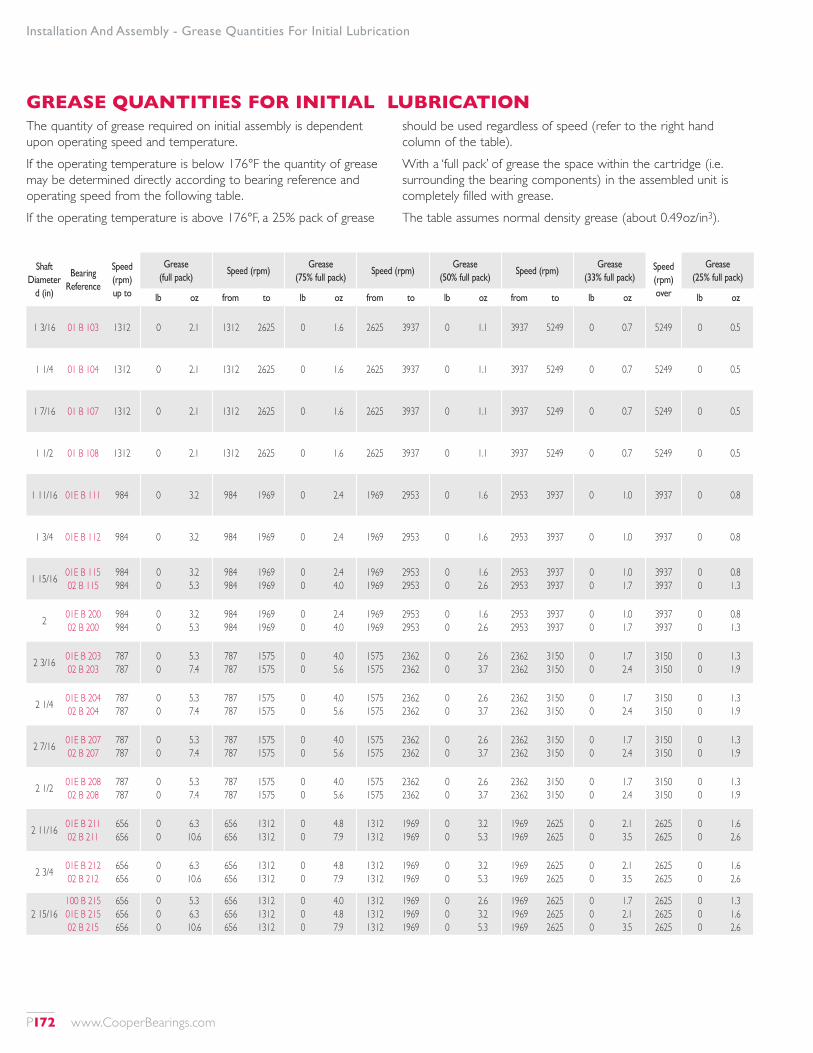
Installation And Assembly - Grease Quantities For Initial Lubrication
Shaft Diameter
d (in)
Bearing Reference
Speed (rpm) up to
Grease (full pack)
Speed (rpm)Grease
(75% full pack)Speed (rpm)
Grease (50% full pack)
Speed (rpm)Grease
(33% full pack)Speed (rpm) over
Grease (25% full pack)
lb oz from to lb oz from to lb oz from to lb oz lb oz
1 3/16 01 B 103 1312 0 2.1 1312 2625 0 1.6 2625 3937 0 1.1 3937 5249 0 0.7 5249 0 0.5
1 1/4 01 B 104 1312 0 2.1 1312 2625 0 1.6 2625 3937 0 1.1 3937 5249 0 0.7 5249 0 0.5
1 7/16 01 B 107 1312 0 2.1 1312 2625 0 1.6 2625 3937 0 1.1 3937 5249 0 0.7 5249 0 0.5
1 1/2 01 B 108 1312 0 2.1 1312 2625 0 1.6 2625 3937 0 1.1 3937 5249 0 0.7 5249 0 0.5
1 11/16 01E B 111 984 0 3.2 984 1969 0 2.4 1969 2953 0 1.6 2953 3937 0 1.0 3937 0 0.8
1 3/4 01E B 112 984 0 3.2 984 1969 0 2.4 1969 2953 0 1.6 2953 3937 0 1.0 3937 0 0.8
1 15/16 01E B 115 02 B 115
984 984
0 0
3.2 5.3
984 984
1969 1969
0 0
2.4 4.0
1969 1969
2953 2953
0 0
1.6 2.6
2953 2953
3937 3937
0 0
1.0 1.7
3937 3937
0 0
0.8 1.3
2 01E B 200 02 B 200
984 984
0 0
3.2 5.3
984 984
1969 1969
0 0
2.4 4.0
1969 1969
2953 2953
0 0
1.6 2.6
2953 2953
3937 3937
0 0
1.0 1.7
3937 3937
0 0
0.8 1.3
2 3/16 01E B 203 02 B 203
787 787
0 0
5.3 7.4
787 787
1575 1575
0 0
4.0 5.6
1575 1575
2362 2362
0 0
2.6 3.7
2362 2362
3150 3150
0 0
1.7 2.4
3150 3150
0 0
1.3 1.9
2 1/4 01E B 204 02 B 204
787 787
0 0
5.3 7.4
787 787
1575 1575
0 0
4.0 5.6
1575 1575
2362 2362
0 0
2.6 3.7
2362 2362
3150 3150
0 0
1.7 2.4
3150 3150
0 0
1.3 1.9
2 7/16 01E B 207 02 B 207
787 787
0 0
5.3 7.4
787 787
1575 1575
0 0
4.0 5.6
1575 1575
2362 2362
0 0
2.6 3.7
2362 2362
3150 3150
0 0
1.7 2.4
3150 3150
0 0
1.3 1.9
2 1/2 01E B 208 02 B 208
787 787
0 0
5.3 7.4
787 787
1575 1575
0 0
4.0 5.6
1575 1575
2362 2362
0 0
2.6 3.7
2362 2362
3150 3150
0 0
1.7 2.4
3150 3150
0 0
1.3 1.9
2 11/16 01E B 211 02 B 211
656 656
0 0
6.3 10.6
656 656
1312 1312
0 0
4.8 7.9
1312 1312
1969 1969
0 0
3.2 5.3
1969 1969
2625 2625
0 0
2.1 3.5
2625 2625
0 0
1.6 2.6
2 3/4 01E B 212 02 B 212
656 656
0 0
6.3 10.6
656 656
1312 1312
0 0
4.8 7.9
1312 1312
1969 1969
0 0
3.2 5.3
1969 1969
2625 2625
0 0
2.1 3.5
2625 2625
0 0
1.6 2.6
2 15/16100 B 215 01E B 215 02 B 215
656 656 656
0 0 0
5.3 6.3 10.6
656 656 656
1312 1312 1312
0 0 0
4.0 4.8 7.9
1312 1312 1312
1969 1969 1969
0 0 0
2.6 3.2 5.3
1969 1969 1969
2625 2625 2625
0 0 0
1.7 2.1 3.5
2625 2625 2625
0 0 0
1.3 1.6 2.6
GREASE QUANTITIES FOR INITIAL LUBRICATIONThe quantity of grease required on initial assembly is dependent upon operating speed and temperature.If the operating temperature is below 176°F the quantity of grease may be determined directly according to bearing reference and operating speed from the following table.If the operating temperature is above 176°F, a 25% pack of grease
should be used regardless of speed (refer to the right hand column of the table).With a ‘full pack’ of grease the space within the cartridge (i.e. surrounding the bearing components) in the assembled unit is completely filled with grease.The table assumes normal density grease (about 0.49oz/in3).
P172 www.CooperBearings.com
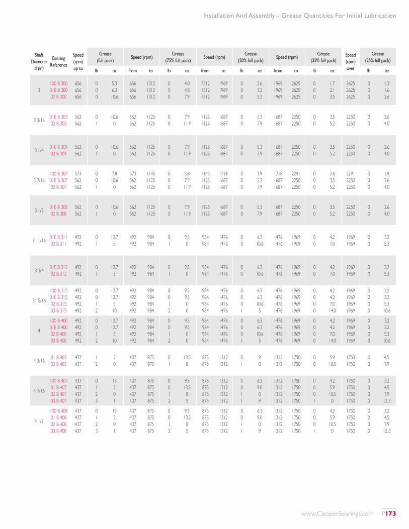
Installation And Assembly - Grease Quantities For Initial Lubrication
Shaft Diameter
d (in)
Bearing Reference
Speed (rpm) up to
Grease (full pack)
Speed (rpm)Grease
(75% full pack)Speed (rpm)
Grease (50% full pack)
Speed (rpm)Grease
(33% full pack)Speed (rpm) over
Grease (25% full pack)
lb oz from to lb oz from to lb oz from to lb oz lb oz
3100 B 300 01E B 300 02 B 300
656 656 656
0 0 0
5.3 6.3 10.6
656 656 656
1312 1312 1312
0 0 0
4.0 4.8 7.9
1312 1312 1312
1969 1969 1969
0 0 0
2.6 3.2 5.3
1969 1969 1969
2625 2625 2625
0 0 0
1.7 2.1 3.5
2625 2625 2625
0 0 0
1.3 1.6 2.6
3 3/16 01E B 303 02 B 303
562 562
0 1
10.6 0
562 562
1125 1125
0 0
7.9 11.9
1125 1125
1687 1687
0 0
5.3 7.9
1687 1687
2250 2250
0 0
3.5 5.2
2250 2250
0 0
2.6 4.0
3 1/4 01E B 304 02 B 304
562 562
0 1
10.6 0
562 562
1125 1125
0 0
7.9 11.9
1125 1125
1687 1687
0 0
5.3 7.9
1687 1687
2250 2250
0 0
3.5 5.2
2250 2250
0 0
2.6 4.0
3 7/16100 B 307 01E B 307 02 B 307
573 562 562
0 0 1
7.8 10.6
0
573 562 562
1145 1125 1125
0 0 0
5.8 7.9 11.9
1145 1125 1125
1718 1687 1687
0 0 0
3.9 5.3 7.9
1718 1687 1687
2291 2250 2250
0 0 0
2.6 3.5 5.2
2291 2250 2250
0 0 0
1.9 2.6 4.0
3 1/2 01E B 308 02 B 308
562 562
0 1
10.6 0
562 562
1125 1125
0 0
7.9 11.9
1125 1125
1687 1687
0 0
5.3 7.9
1687 1687
2250 2250
0 0
3.5 5.2
2250 2250
0 0
2.6 4.0
3 11/16 01E B 311 02 B 311
492 492
0 1
12.7 5
492 492
984 984
0 1
9.5 0
984 984
1476 1476
0 0
6.3 10.6
1476 1476
1969 1969
0 0
4.2 7.0
1969 1969
0 0
3.2 5.3
3 3/4 01E B 312 02 B 312
492 492
0 1
12.7 5
492 492
984 984
0 1
9.5 0
984 984
1476 1476
0 0
6.3 10.6
1476 1476
1969 1969
0 0
4.2 7.0
1969 1969
0 0
3.2 5.3
3 15/16
100 B 315 01E B 315 02 B 315 03 B 315
492 492 492 492
0 0 1 2
12.7 12.7
5 10
492 492 492 492
984 984 984 984
0 0 1 2
9.5 9.5 0 0
984 984 984 984
1476 1476 1476 1476
0 0 0 1
6.3 6.3 10.6
5
1476 1476 1476 1476
1969 1969 1969 1969
0 0 0 0
4.2 4.2 7.0 14.0
1969 1969 1969 1969
0 0 0 0
3.2 3.2 5.3 10.6
4
100 B 400 01E B 400 02 B 400 03 B 400
492 492 492 492
0 0 1 2
12.7 12.7
5 10
492 492 492 492
984 984 984 984
0 0 1 2
9.5 9.5 0 0
984 984 984 984
1476 1476 1476 1476
0 0 0 1
6.3 6.3 10.6
5
1476 1476 1476 1476
1969 1969 1969 1969
0 0 0 0
4.2 4.2 7.0 14.0
1969 1969 1969 1969
0 0 0 0
3.2 3.2 5.3 10.6
4 3/16 01 B 403 02 B 403
437 437
1 2
2 0
437 437
875 875
0 1
13.5 8
875 875
1312 1312
0 1
9 0
1312 1312
1750 1750
0 0
5.9 10.5
1750 1750
0 0
4.5 7.9
4 7/16
100 B 407 01 B 407 02 B 407 03 B 407
437 437 437 437
0 1 2 3
13 2 0 1
437 437 437 437
875 875 875 875
0 0 1 2
9.5 13.5
8 5
875 875 875 875
1312 1312 1312 1312
0 0 1 1
6.3 9.0 0 9
1312 1312 1312 1312
1750 1750 1750 1750
0 0 0 1
4.2 5.9 10.5
0
1750 1750 1750 1750
0 0 0 0
3.2 4.5 7.9
12..3
4 1/2
100 B 408 01 B 408 02 B 408 03 B 408
437 437 437 437
0 1 2 3
13 2 0 1
437 437 437 437
875 875 875 875
0 0 1 2
9.5 13.5
8 5
875 875 875 875
1312 1312 1312 1312
0 0 1 1
6.3 9.0 0 9
1312 1312 1312 1312
1750 1750 1750 1750
0 0 0 1
4.2 5.9 10.5
0
1750 1750 1750 1750
0 0 0 0
3.2 4.5 7.9
12..3
www.CooperBearings.com P173
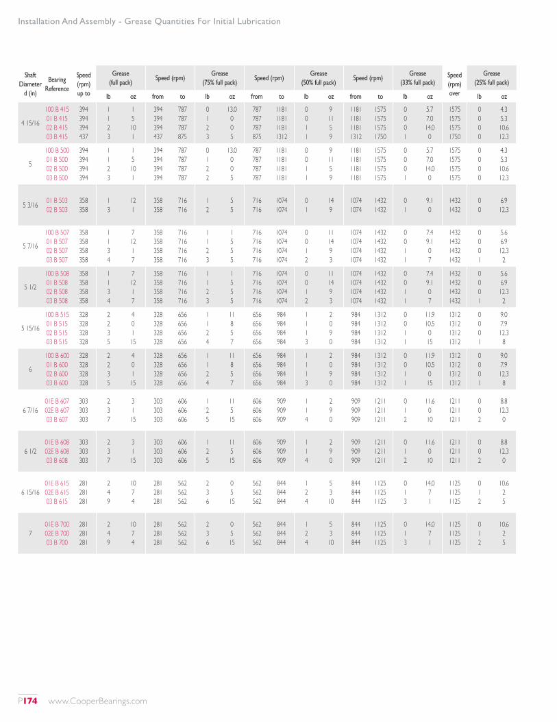
Installation And Assembly - Grease Quantities For Initial Lubrication
Shaft Diameter
d (in)
Bearing Reference
Speed (rpm) up to
Grease (full pack)
Speed (rpm)Grease
(75% full pack)Speed (rpm)
Grease (50% full pack)
Speed (rpm)Grease
(33% full pack)Speed (rpm) over
Grease (25% full pack)
lb oz from to lb oz from to lb oz from to lb oz lb oz
4 15/16
100 B 415 01 B 415 02 B 415 03 B 415
394 394 394 437
1 1 2 3
1 5 10 1
394 394 394 437
787 787 787 875
0 1 2 3
13.0 0 0 5
787 787 787 875
1181 1181 1181 1312
0 0 1 1
9 11 5 9
1181 1181 1181 1312
1575 1575 1575 1750
0 0 0 1
5.7 7.0 14.0
0
1575 1575 1575 1750
0 0 0 0
4.3 5.3 10.6 12.3
5
100 B 500 01 B 500 02 B 500 03 B 500
394 394 394 394
1 1 2 3
1 5 10 1
394 394 394 394
787 787 787 787
0 1 2 2
13.0 0 0 5
787 787 787 787
1181 1181 1181 1181
0 0 1 1
9 11 5 9
1181 1181 1181 1181
1575 1575 1575 1575
0 0 0 1
5.7 7.0 14.0
0
1575 1575 1575 1575
0 0 0 0
4.3 5.3 10.6 12.3
5 3/16 01 B 503 02 B 503
358 358
1 3
12 1
358 358
716 716
1 2
5 5
716 716
1074 1074
0 1
14 9
1074 1074
1432 1432
0 1
9.1 0
1432 1432
0 0
6.9 12.3
5 7/16
100 B 507 01 B 507 02 B 507 03 B 507
358 358 358 358
1 1 3 4
7 12 1 7
358 358 358 358
716 716 716 716
1 1 2 3
1 5 5 5
716 716 716 716
1074 1074 1074 1074
0 0 1 2
11 14 9 3
1074 1074 1074 1074
1432 1432 1432 1432
0 0 1 1
7.4 9.1 0 7
1432 1432 1432 1432
0 0 0 1
5.6 6.9 12.3
2
5 1/2
100 B 508 01 B 508 02 B 508 03 B 508
358 358 358 358
1 1 3 4
7 12 1 7
358 358 358 358
716 716 716 716
1 1 2 3
1 5 5 5
716 716 716 716
1074 1074 1074 1074
0 0 1 2
11 14 9 3
1074 1074 1074 1074
1432 1432 1432 1432
0 0 1 1
7.4 9.1 0 7
1432 1432 1432 1432
0 0 0 1
5.6 6.9 12.3
2
5 15/16
100 B 515 01 B 515 02 B 515 03 B 515
328 328 328 328
2 2 3 5
4 0 1 15
328 328 328 328
656 656 656 656
1 1 2 4
11 8 5 7
656 656 656 656
984 984 984 984
1 1 1 3
2 0 9 0
984 984 984 984
1312 1312 1312 1312
0 0 1 1
11.9 10.5
0 15
1312 1312 1312 1312
0 0 0 1
9.0 7.9 12.3
8
6
100 B 600 01 B 600 02 B 600 03 B 600
328 328 328 328
2 2 3 5
4 0 1 15
328 328 328 328
656 656 656 656
1 1 2 4
11 8 5 7
656 656 656 656
984 984 984 984
1 1 1 3
2 0 9 0
984 984 984 984
1312 1312 1312 1312
0 0 1 1
11.9 10.5
0 15
1312 1312 1312 1312
0 0 0 1
9.0 7.9 12.3
8
6 7/1601E B 607 02E B 607 03 B 607
303 303 303
2 3 7
3 1 15
303 303 303
606 606 606
1 2 5
11 5 15
606 606 606
909 909 909
1 1 4
2 9 0
909 909 909
1211 1211 1211
0 1 2
11.6 0 10
1211 1211 1211
0 0 2
8.8 12.3
0
6 1/201E B 608 02E B 608 03 B 608
303 303 303
2 3 7
3 1 15
303 303 303
606 606 606
1 2 5
11 5 15
606 606 606
909 909 909
1 1 4
2 9 0
909 909 909
1211 1211 1211
0 1 2
11.6 0 10
1211 1211 1211
0 0 2
8.8 12.3
0
6 15/1601E B 615 02E B 615 03 B 615
281 281 281
2 4 9
10 7 4
281 281 281
562 562 562
2 3 6
0 5 15
562 562 562
844 844 844
1 2 4
5 3 10
844 844 844
1125 1125 1125
0 1 3
14.0 7 1
1125 1125 1125
0 1 2
10.6 2 5
701E B 700 02E B 700 03 B 700
281 281 281
2 4 9
10 7 4
281 281 281
562 562 562
2 3 6
0 5 15
562 562 562
844 844 844
1 2 4
5 3 10
844 844 844
1125 1125 1125
0 1 3
14.0 7 1
1125 1125 1125
0 1 2
10.6 2 5
P174 www.CooperBearings.com
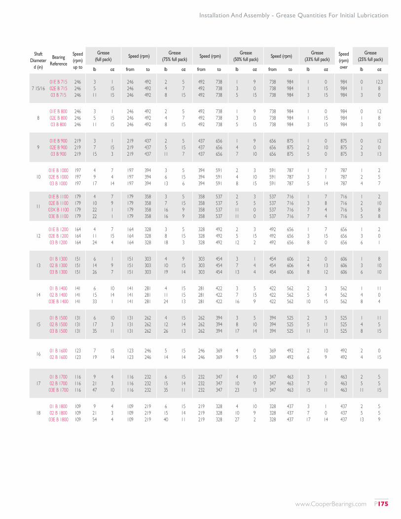
Installation And Assembly - Grease Quantities For Initial Lubrication
Shaft Diameter
d (in)
Bearing Reference
Speed (rpm) up to
Grease (full pack)
Speed (rpm)Grease
(75% full pack)Speed (rpm)
Grease (50% full pack)
Speed (rpm)Grease
(33% full pack)Speed (rpm) over
Grease (25% full pack)
lb oz from to lb oz from to lb oz from to lb oz lb oz
7 15/1601E B 715 02E B 715 03 B 715
246 246 246
3 5 11
1 15 15
246 246 246
492 492 492
2 4 8
5 7 15
492 492 492
738 738 738
1 3 5
9 0 15
738 738 738
984 984 984
1 1 3
0 15 15
984 984 984
0 1 3
12.3 8 0
801E B 800 02E B 800 03 B 800
246 246 246
3 5 11
1 15 15
246 246 246
492 492 492
2 4 8
5 7 15
492 492 492
738 738 738
1 3 5
9 0 15
738 738 738
984 984 984
1 1 3
0 15 15
984 984 984
0 1 3
12 8 0
901E B 900 02E B 900 03 B 900
219 219 219
3 7 15
1 15 3
219 219 219
437 437 437
2 5 11
5 15 7
437 437 437
656 656 656
1 4 7
9 0 10
656 656 656
875 875 875
1 2 5
0 10 0
875 875 875
0 2 3
12 0 13
1001E B 1000 02E B 1000 03 B 1000
197 197 197
4 9 17
7 4 14
197 197 197
394 394 394
3 6 13
5 15 6
394 394 394
591 591 591
2 4 8
3 10 15
591 591 591
787 787 787
1 3 5
7 1 14
787 787 787
1 2 4
2 5 7
11
01E B 1100 02E B 1100 03X B 1100 03E B 1100
179 179 179 179
4 10 22 22
7 9 1 1
179 179 179 179
358 358 358 358
3 7 16 16
5 15 9 9
358 358 358 358
537 537 537 537
2 5 11 11
3 5 0 0
537 537 537 537
716 716 716 716
1 3 7 7
7 8 4 4
716 716 716 716
1 2 5 5
2 10 8 8
1201E B 1200 02E B 1200 03 B 1200
164 164 164
4 11 24
7 15 4
164 164 164
328 328 328
3 8 18
5 15 3
328 328 328
492 492 492
2 5 12
3 15 2
492 492 492
656 656 656
1 3 8
7 15 0
656 656 656
1 3 6
2 0 1
1301 B 1300 02 B 1300 03 B 1300
151 151 151
6 14 26
1 9 7
151 151 151
303 303 303
4 10 19
9 15 14
303 303 303
454 454 454
3 7 13
1 4 4
454 454 454
606 606 606
2 4 8
0 13 12
606 606 606
1 3 6
8 10 10
1401 B 1400 02 B 1400 03E B 1400
141 141 141
6 15 33
10 14 1
141 141 141
281 281 281
4 11 24
15 15 13
281 281 281
422 422 422
3 7 16
5 15 9
422 422 422
562 562 562
2 5 10
3 4 15
562 562 562
1 4 8
11 0 4
1501 B 1500 02 B 1500 03 B 1500
131 131 131
6 17 35
10 3 11
131 131 131
262 262 262
4 12 26
15 14 13
262 262 262
394 394 394
3 8 17
5 10 14
394 394 394
525 525 525
2 5 11
3 11 13
525 525 525
1 4 8
11 5 15
16 01 B 1600 02 B 1600
123 123
7 19
15 14
123 123
246 246
5 14
15 14
246 246
369 369
4 9
0 15
369 369
492 492
2 6
10 9
492 492
2 4
0 15
1701 B 1700 02 B 1700 03E B 1700
116 116 116
9 21 47
4 3 10
116 116 116
232 232 232
6 15 35
15 14 11
232 232 232
347 347 347
4 10 23
10 9 13
347 347 347
463 463 463
3 7 15
1 0 11
463 463 463
2 5 11
5 5 15
1801 B 1800 02 B 1800 03E B 1800
109 109 109
9 21 54
4 3 4
109 109 109
219 219 219
6 15 40
15 14 11
219 219 219
328 328 328
4 10 27
10 9 2
328 328 328
437 437 437
3 7 17
1 0 14
437 437 437
2 5 13
5 5 9
www.CooperBearings.com P175
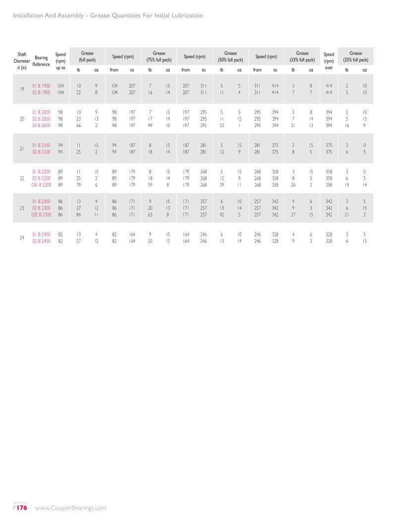
Installation And Assembly - Grease Quantities For Initial Lubrication
Shaft Diameter
d (in)
Bearing Reference
Speed (rpm) up to
Grease (full pack)
Speed (rpm)Grease
(75% full pack)Speed (rpm)
Grease (50% full pack)
Speed (rpm)Grease
(33% full pack)Speed (rpm) over
Grease (25% full pack)
lb oz from to lb oz from to lb oz from to lb oz lb oz
19 01 B 1900 02 B 1900
104 104
10 22
9 8
104 104
207 207
7 16
15 14
207 207
311 311
5 11
5 4
311 311
414 414
3 7
8 7
414 414
2 5
10 10
2001 B 2000 02 B 2000 03 B 2000
98 98 98
10 23 66
9 13 2
98 98 98
197 197 197
7 17 49
15 14 10
197 197 197
295 295 295
5 11 33
5 15 1
295 295 295
394 394 394
3 7 21
8 14 13
394 394 394
2 5 16
10 15 9
21 01 B 2100 02 B 2100
94 94
11 25
15 2
94 94
187 187
8 18
15 14
187 187
281 281
5 12
15 9
281 281
375 375
3 8
15 5
375 375
3 6
0 5
2201 B 2200 02 B 2200 03E B 2200
89 89 89
11 25 79
15 2 6
89 89 89
179 179 179
8 18 59
15 14 8
179 179 179
268 268 268
5 12 39
15 9 11
268 268 268
358 358 358
3 8 26
15 5 3
358 358 358
3 6 19
0 5 14
2301 B 2300 02 B 2300 03E B 2300
86 86 86
13 27 84
4 12 11
86 86 86
171 171 171
9 20 63
15 13 8
171 171 171
257 257 257
6 13 42
10 14 5
257 257 257
342 342 342
4 9 27
6 3 15
342 342 342
3 6 21
5 15 3
24 01 B 2400 02 B 2400
82 82
13 27
4 12
82 82
164 164
9 20
15 13
164 164
246 246
6 13
10 14
246 246
328 328
4 9
6 3
328 328
3 6
5 15
P176 www.CooperBearings.com
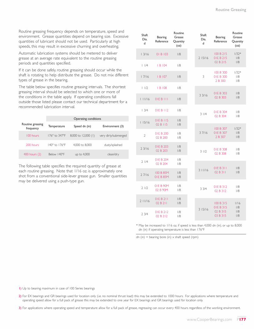
Routine Greasing
Routine greasing frequency depends on temperature, speed and environment. Grease quantities depend on bearing size. Excessive quantities of lubricant should not be used. Particularly at high speeds, this may result in excessive churning and overheating.Automatic lubrication systems should be metered to deliver grease at an average rate equivalent to the routine greasing periods and quantities specified.If it can be done safely, routine greasing should occur while the shaft is rotating to help distribute the grease. Do not mix different types of grease in the bearing.The table below specifies routine greasing intervals. The shortest greasing interval should be selected to which one or more of the conditions in the table apply. If operating conditions fall outside those listed please contact our technical department for a recommended lubrication interval.
The following table specifies the required quantity of grease at each routine greasing. Note that 1/16 oz. is approximately one shot from a conventional side-lever grease gun. Smaller quantities may be delivered using a push-type gun.
1) Up to bearing maximum in case of 100 Series bearings
2) For EX bearings and GR bearings used for location only (i.e. no nominal thrust load) this may be extended to 1000 hours. For applications where temperature and operating speed allow for a full pack of grease this may be extended to one year for EX bearings and GR bearings used for location only.
3) For applications where operating speed and temperature allow for a full pack of grease, regreasing can occur every 400 hours regardless of the working environment.
* May be increased to 1/16 oz. if speed is less than 4,000 dn (in), or up to 8,000 dn (in) if operating temperature is less than 176°F
Shaft Dia. d
Bearing Reference
Routine Grease
Quantity (oz)
1 3/16 01 B 103 1/8
1 1/4 1 B 104 1/8
1 7/16 1 B 107 1/8
1 1/2 1 B 108 1/8
1 11/16 01E B 111 1/8
1 3/4 01E B 112 1/8
1 15/16 01E B 115 02 B 115
1/8 1/8
2 01E B 200 02 B 200
1/8 1/8
2 3/16 01E B 203 02 B 203
1/8 1/8
2 1/4 01E B 204 02 B 204
1/8 1/8
2 7/16 100 B 85M 01E B 85M
1/8 1/8
2 1/2 01E B 90M 02 B 90M
1/8 1/8
2 11/16 01E B 211 02 B 211
1/8 1/8
2 3/4 01E B 212 02 B 212
1/8 1/8
Shaft Dia. d
Bearing Reference
Routine Grease
Quantity (oz)
2 15/16100 B 215 01E B 215 02 B 215
1/32* 1/8 1/8
3100 B 300 01E B 300 2 B 300
1/32* 1/8 1/8
3 3/16 01E B 303 02 B 303
1/8 1/8
3 1/4 01E B 304 02 B 304
1/8 1/8
3 7/16100 B 307 01E B 307 2 B 307
1/32* 1/8 1/8
3 1/2 01E B 308 02 B 308
1/8 1/8
3 11/16 01E B 311 02 B 311
1/8 1/8
3 3/4 01E B 312 02 B 312
1/8 1/8
3 15/16
100 B 315 01E B 315 02 B 315 03 B 315
1/16 1/8 1/8 1/8
Operating conditions
Routine greasing frequency
Temperature Speed dn (in) Environment (3)
100 hours 176° to 347°F 8,000 to 12,000 (1) very dirty/submerged
200 hours 140° to 176°F 4,000 to 8,000 dusty/splashed
400 hours (2) Below 140°F up to 4,000 clean/dry
dn (in) = bearing bore (in) x shaft speed (rpm)
www.CooperBearings.com P177
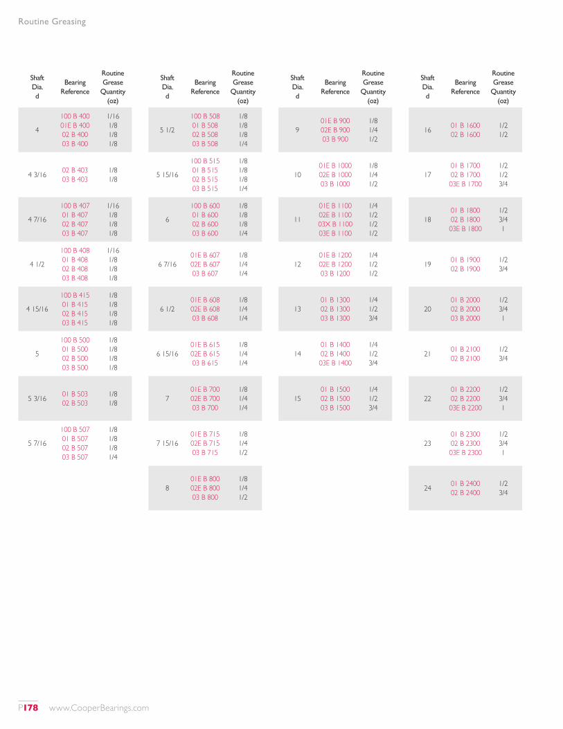
Shaft Dia. d
Bearing Reference
Routine Grease
Quantity (oz)
4
100 B 400 01E B 400 02 B 400 03 B 400
1/16 1/8 1/8 1/8
4 3/16 02 B 403 03 B 403
1/8 1/8
4 7/16
100 B 407 01 B 407 02 B 407 03 B 407
1/16 1/8 1/8 1/8
4 1/2
100 B 408 01 B 408 02 B 408 03 B 408
1/16 1/8 1/8 1/8
4 15/16
100 B 415 01 B 415 02 B 415 03 B 415
1/8 1/8 1/8 1/8
5
100 B 500 01 B 500 02 B 500 03 B 500
1/8 1/8 1/8 1/8
5 3/16 01 B 503 02 B 503
1/8 1/8
5 7/16
100 B 507 01 B 507 02 B 507 03 B 507
1/8 1/8 1/8 1/4
Shaft Dia. d
Bearing Reference
Routine Grease
Quantity (oz)
901E B 900 02E B 900 03 B 900
1/8 1/4 1/2
1001E B 1000 02E B 1000 03 B 1000
1/8 1/4 1/2
11
01E B 1100 02E B 1100 03X B 1100 03E B 1100
1/4 1/2 1/2 1/2
1201E B 1200 02E B 1200 03 B 1200
1/4 1/2 1/2
1301 B 1300 02 B 1300 03 B 1300
1/4 1/2 3/4
1401 B 1400 02 B 1400 03E B 1400
1/4 1/2 3/4
1501 B 1500 02 B 1500 03 B 1500
1/4 1/2 3/4
Shaft Dia. d
Bearing Reference
Routine Grease
Quantity (oz)
5 1/2
100 B 508 01 B 508 02 B 508 03 B 508
1/8 1/8 1/8 1/4
5 15/16
100 B 515 01 B 515 02 B 515 03 B 515
1/8 1/8 1/8 1/4
6
100 B 600 01 B 600 02 B 600 03 B 600
1/8 1/8 1/8 1/4
6 7/1601E B 607 02E B 607 03 B 607
1/8 1/4 1/4
6 1/201E B 608 02E B 608 03 B 608
1/8 1/4 1/4
6 15/1601E B 615 02E B 615 03 B 615
1/8 1/4 1/4
701E B 700 02E B 700 03 B 700
1/8 1/4 1/4
7 15/1601E B 715 02E B 715 03 B 715
1/8 1/4 1/2
801E B 800 02E B 800 03 B 800
1/8 1/4 1/2
Shaft Dia. d
Bearing Reference
Routine Grease
Quantity (oz)
16 01 B 1600 02 B 1600
1/2 1/2
1701 B 1700 02 B 1700 03E B 1700
1/2 1/2 3/4
1801 B 1800 02 B 1800 03E B 1800
1/2 3/4 1
19 01 B 1900 02 B 1900
1/2 3/4
2001 B 2000 02 B 2000 03 B 2000
1/2 3/4 1
21 01 B 2100 02 B 2100
1/2 3/4
2201 B 2200 02 B 2200 03E B 2200
1/2 3/4 1
2301 B 2300 02 B 2300 03E B 2300
1/2 3/4 1
24 01 B 2400 02 B 2400
1/2 3/4
Routine Greasing
P178 www.CooperBearings.com
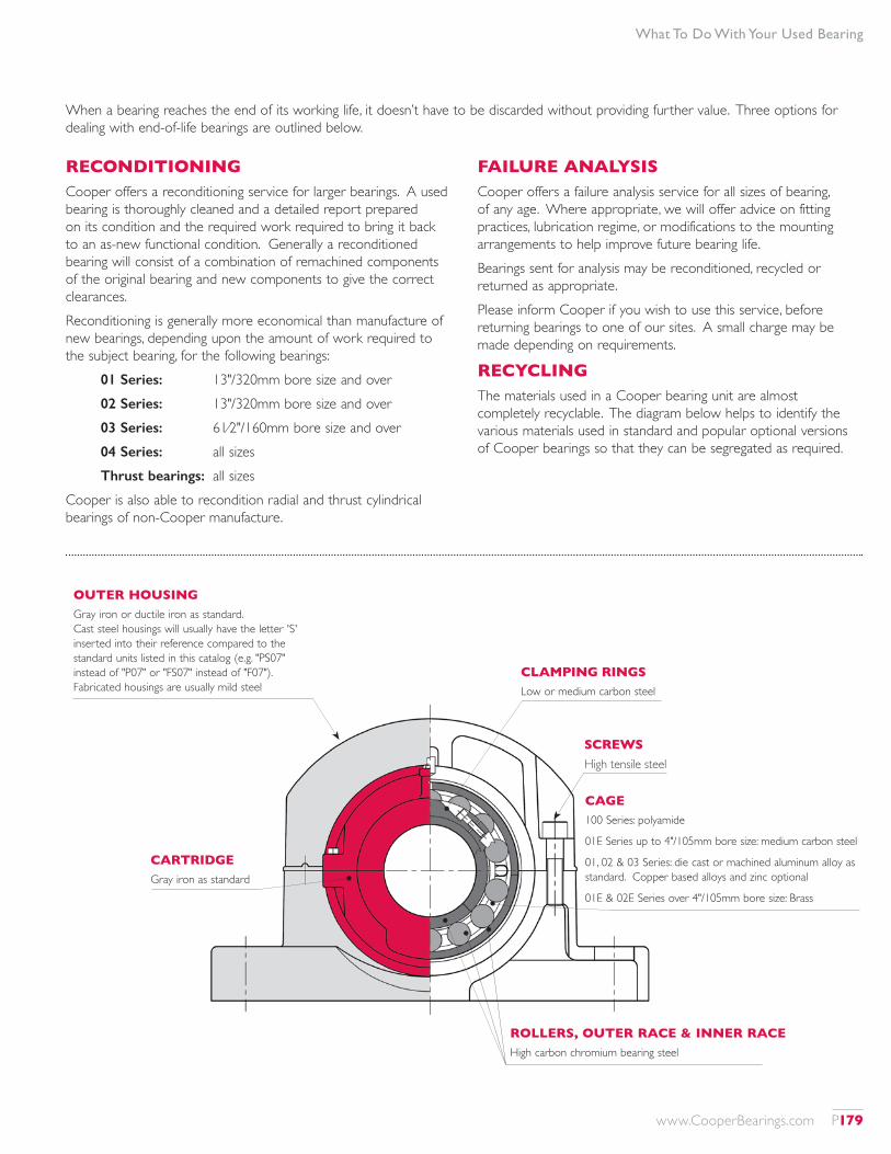
What To Do With Your Used Bearing
When a bearing reaches the end of its working life, it doesn’t have to be discarded without providing further value. Three options for dealing with end-of-life bearings are outlined below.
RECONDITIONINGCooper offers a reconditioning service for larger bearings. A used bearing is thoroughly cleaned and a detailed report prepared on its condition and the required work required to bring it back to an as-new functional condition. Generally a reconditioned bearing will consist of a combination of remachined components of the original bearing and new components to give the correct clearances.Reconditioning is generally more economical than manufacture of new bearings, depending upon the amount of work required to the subject bearing, for the following bearings:
01 Series: 13"/320mm bore size and over 02 Series: 13"/320mm bore size and over 03 Series: 61⁄2"/160mm bore size and over 04 Series: all sizesThrust bearings: all sizes
Cooper is also able to recondition radial and thrust cylindrical bearings of non-Cooper manufacture.
FAILURE ANALYSISCooper offers a failure analysis service for all sizes of bearing, of any age. Where appropriate, we will offer advice on fitting practices, lubrication regime, or modifications to the mounting arrangements to help improve future bearing life.Bearings sent for analysis may be reconditioned, recycled or returned as appropriate.Please inform Cooper if you wish to use this service, before returning bearings to one of our sites. A small charge may be made depending on requirements.
RECYCLINGThe materials used in a Cooper bearing unit are almost completely recyclable. The diagram below helps to identify the various materials used in standard and popular optional versions of Cooper bearings so that they can be segregated as required.
OUTER HOUSINGGray iron or ductile iron as standard.Cast steel housings will usually have the letter 'S' inserted into their reference compared to the standard units listed in this catalog (e.g. "PS07" instead of "P07" or "FS07" instead of "F07"). Fabricated housings are usually mild steel
CARTRIDGEGray iron as standard
CLAMPING RINGSLow or medium carbon steel
SCREWSHigh tensile steel
CAGE100 Series: polyamide
01E Series up to 4"/105mm bore size: medium carbon steel
01, 02 & 03 Series: die cast or machined aluminum alloy as standard. Copper based alloys and zinc optional
01E & 02E Series over 4"/105mm bore size: Brass
ROLLERS, OUTER RACE & INNER RACEHigh carbon chromium bearing steel
www.CooperBearings.com P179
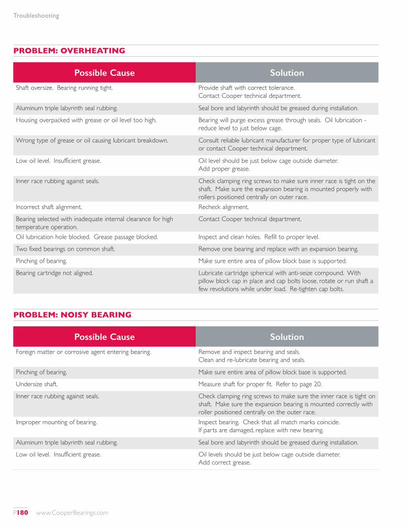
Troubleshooting
Possible Cause Solution
Foreign matter or corrosive agent entering bearing. Remove and inspect bearing and seals. Clean and re-lubricate bearing and seals.
Pinching of bearing. Make sure entire area of pillow block base is supported.
Undersize shaft. Measure shaft for proper fit. Refer to page 20.
Inner race rubbing against seals. Check clamping ring screws to make sure the inner race is tight on shaft. Make sure the expansion bearing is mounted correctly with roller positioned centrally on the outer race.
Improper mounting of bearing. Inspect bearing. Check that all match marks coincide. If parts are damaged, replace with new bearing.
Aluminum triple labyrinth seal rubbing. Seal bore and labyrinth should be greased during installation.
Low oil level. Insufficient grease. Oil levels should be just below cage outside diameter. Add correct grease.
Possible Cause Solution
Shaft oversize. Bearing running tight. Provide shaft with correct tolerance. Contact Cooper technical department.
Aluminum triple labyrinth seal rubbing. Seal bore and labyrinth should be greased during installation.
Housing overpacked with grease or oil level too high. Bearing will purge excess grease through seals. Oil lubrication - reduce level to just below cage.
Wrong type of grease or oil causing lubricant breakdown. Consult reliable lubricant manufacturer for proper type of lubricant or contact Cooper technical department.
Low oil level. Insufficient grease. Oil level should be just below cage outside diameter. Add proper grease.
Inner race rubbing against seals. Check clamping ring screws to make sure inner race is tight on the shaft. Make sure the expansion bearing is mounted properly with rollers positioned centrally on outer race.
Incorrect shaft alignment. Recheck alignment.
Bearing selected with inadequate internal clearance for high temperature operation.
Contact Cooper technical department.
Oil lubrication hole blocked. Grease passage blocked. Inspect and clean holes. Refill to proper level.
Two fixed bearings on common shaft. Remove one bearing and replace with an expansion bearing.
Pinching of bearing. Make sure entire area of pillow block base is supported.
Bearing cartridge not aligned. Lubricate cartridge spherical with anti-seize compound. With pillow block cap in place and cap bolts loose, rotate or run shaft a few revolutions while under load. Re-tighten cap bolts.
PROBLEM: NOISY BEARING
PROBLEM: OVERHEATING
P180 www.CooperBearings.com
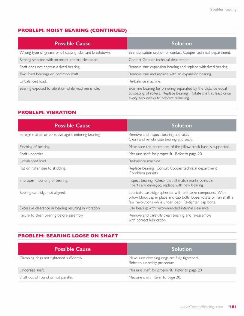
Troubleshooting
Possible Cause Solution
Wrong type of grease or oil causing lubricant breakdown. See lubrication section or contact Cooper technical department.
Bearing selected with incorrect internal clearance. Contact Cooper technical department.
Shaft does not contain a fixed bearing. Remove one expansion bearing and replace with fixed bearing.
Two fixed bearings on common shaft. Remove one and replace with an expansion bearing.
Unbalanced load. Re-balance machine.
Bearing exposed to vibration while machine is idle. Examine bearing for brinelling separated by the distance equal to spacing of rollers. Replace bearing. Rotate shaft at least once every two weeks to prevent brinelling.
Possible Cause Solution
Foreign matter or corrosive agent entering bearing. Remove and inspect bearing and seals. Clean and re-lubricate bearing and seals.
Pinching of bearing. Make sure the entire area of the pillow block base is supported.
Shaft undersize. Measure shaft for proper fit. Refer to page 20.
Unbalanced load. Re-balance machine.
Flat on roller due to skidding. Replace bearing. Consult Cooper technical department if problem persists.
Improper mounting of bearing. Inspect bearing. Check that all match marks coincide. If parts are damaged, replace with new bearing.
Bearing cartridge not aligned. Lubricate cartridge spherical with anti-seize compound. With pillow block cap in place and cap bolts loose, rotate or run shaft a few revolutions while under load. Re-tighten cap bolts.
Excessive clearance in bearing resulting in vibration. Use bearing with recommended internal clearance.
Failure to clean bearing before assembly. Remove and carefully clean bearing and re-assemble with correct lubrication.
Possible Cause Solution
Clamping rings not tightened sufficiently. Make sure clamping rings are fully tightened. Refer to assembly procedure.
Undersize shaft. Measure shaft for proper fit. Refer to page 20.
Shaft out of round or not parallel. Measure shaft. Refer to page 20.
PROBLEM: NOISY BEARING (CONTINUED)
PROBLEM: VIBRATION
PROBLEM: BEARING LOOSE ON SHAFT
www.CooperBearings.com P181
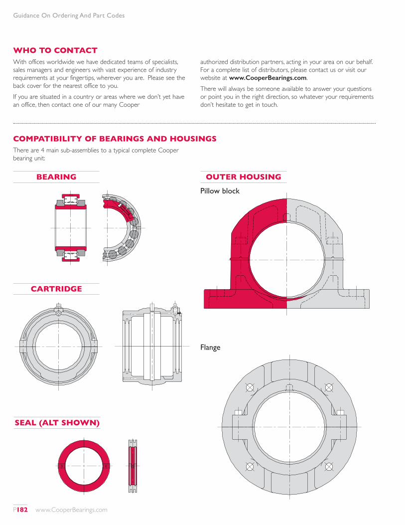
Guidance On Ordering And Part Codes
WHO TO CONTACTWith offices worldwide we have dedicated teams of specialists, sales managers and engineers with vast experience of industry requirements at your fingertips, wherever you are. Please see the back cover for the nearest office to you.If you are situated in a country or areas where we don’t yet have an office, then contact one of our many Cooper
authorized distribution partners, acting in your area on our behalf. For a complete list of distributors, please contact us or visit our website at www.CooperBearings.com.There will always be someone available to answer your questions or point you in the right direction, so whatever your requirements don’t hesitate to get in touch.
COMPATIBILITY OF BEARINGS AND HOUSINGSThere are 4 main sub-assemblies to a typical complete Cooper bearing unit:
BEARING
CARTRIDGE
SEAL (ALT SHOWN)
OUTER HOUSING
Pillow block
Flange
P182 www.CooperBearings.com
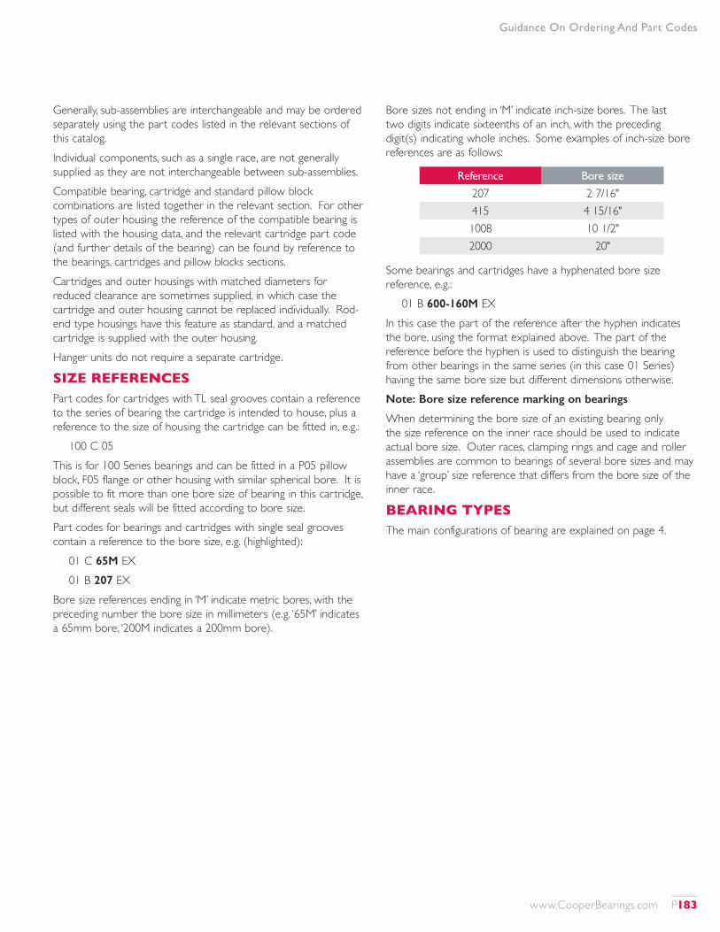
Guidance On Ordering And Part Codes
Generally, sub-assemblies are interchangeable and may be ordered separately using the part codes listed in the relevant sections of this catalog.Individual components, such as a single race, are not generally supplied as they are not interchangeable between sub-assemblies.Compatible bearing, cartridge and standard pillow block combinations are listed together in the relevant section. For other types of outer housing the reference of the compatible bearing is listed with the housing data, and the relevant cartridge part code (and further details of the bearing) can be found by reference to the bearings, cartridges and pillow blocks sections.Cartridges and outer housings with matched diameters for reduced clearance are sometimes supplied, in which case the cartridge and outer housing cannot be replaced individually. Rod-end type housings have this feature as standard, and a matched cartridge is supplied with the outer housing.Hanger units do not require a separate cartridge.
SIZE REFERENCESPart codes for cartridges with TL seal grooves contain a reference to the series of bearing the cartridge is intended to house, plus a reference to the size of housing the cartridge can be fitted in, e.g.:
100 C 05This is for 100 Series bearings and can be fitted in a P05 pillow block, F05 flange or other housing with similar spherical bore. It is possible to fit more than one bore size of bearing in this cartridge, but different seals will be fitted according to bore size.Part codes for bearings and cartridges with single seal grooves contain a reference to the bore size, e.g. (highlighted):
01 C 65M EX01 B 207 EX
Bore size references ending in ‘M’ indicate metric bores, with the preceding number the bore size in millimeters (e.g. ‘65M’ indicates a 65mm bore, ‘200M indicates a 200mm bore).
Bore sizes not ending in ‘M’ indicate inch-size bores. The last two digits indicate sixteenths of an inch, with the preceding digit(s) indicating whole inches. Some examples of inch-size bore references are as follows:
Reference Bore size
207 2 7/16"415 4 15/16"1008 10 1/2"2000 20"
Some bearings and cartridges have a hyphenated bore size reference, e.g.:
01 B 600-160M EXIn this case the part of the reference after the hyphen indicates the bore, using the format explained above. The part of the reference before the hyphen is used to distinguish the bearing from other bearings in the same series (in this case 01 Series) having the same bore size but different dimensions otherwise.Note: Bore size reference marking on bearings
When determining the bore size of an existing bearing only the size reference on the inner race should be used to indicate actual bore size. Outer races, clamping rings and cage and roller assemblies are common to bearings of several bore sizes and may have a ‘group’ size reference that differs from the bore size of the inner race.
BEARING TYPESThe main configurations of bearing are explained on page 4.
www.CooperBearings.com P183
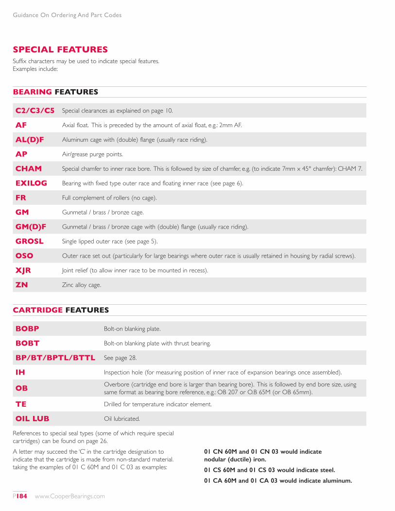
SPECIAL FEATURESSuffix characters may be used to indicate special features. Examples include:
BEARING FEATURES
C2/C3/C5 Special clearances as explained on page 10.
AF Axial float. This is preceded by the amount of axial float, e.g.: 2mm AF.
AL(D)F Aluminum cage with (double) flange (usually race riding).
AP Air/grease purge points.
CHAM Special chamfer to inner race bore. This is followed by size of chamfer, e.g. (to indicate 7mm x 45° chamfer): CHAM 7.
EXILOG Bearing with fixed type outer race and floating inner race (see page 6).
FR Full complement of rollers (no cage).
GM Gunmetal / brass / bronze cage.
GM(D)F Gunmetal / brass / bronze cage with (double) flange (usually race riding).
GROSL Single lipped outer race (see page 5).
OSO Outer race set out (particularly for large bearings where outer race is usually retained in housing by radial screws).
XJR Joint relief (to allow inner race to be mounted in recess).
ZN Zinc alloy cage.
CARTRIDGE FEATURES
BOBP Bolt-on blanking plate.
BOBT Bolt-on blanking plate with thrust bearing.
BP/BT/BPTL/BTTL See page 28.
IH Inspection hole (for measuring position of inner race of expansion bearings once assembled).
OB Overbore (cartridge end bore is larger than bearing bore). This is followed by end bore size, using same format as bearing bore reference, e.g.: OB 207 or O.B 65M (or OB 65mm).
TE Drilled for temperature indicator element.
OIL LUB Oil lubricated.
Guidance On Ordering And Part Codes
References to special seal types (some of which require special cartridges) can be found on page 26.A letter may succeed the ‘C’ in the cartridge designation to indicate that the cartridge is made from non-standard material. taking the examples of 01 C 60M and 01 C 03 as examples:
01 CN 60M and 01 CN 03 would indicate nodular (ductile) iron.
01 CS 60M and 01 CS 03 would indicate steel.
01 CA 60M and 01 CA 03 would indicate aluminum.
P184 www.CooperBearings.com
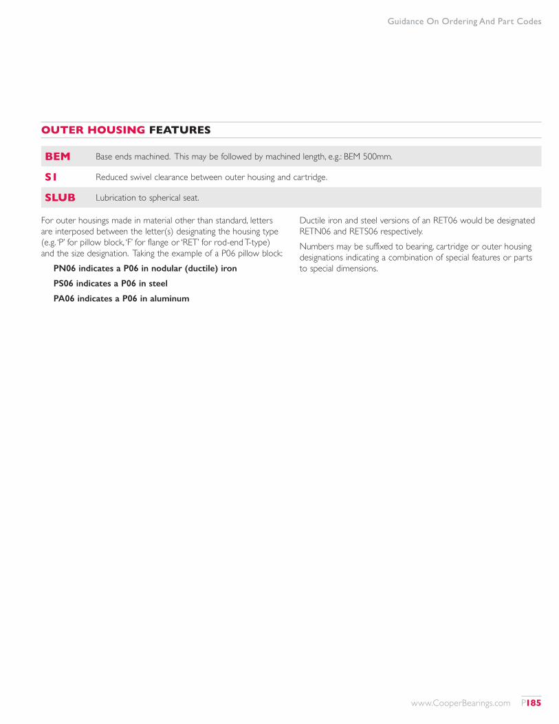
OUTER HOUSING FEATURES
BEM Base ends machined. This may be followed by machined length, e.g.: BEM 500mm.
S1 Reduced swivel clearance between outer housing and cartridge.
SLUB Lubrication to spherical seat.
Guidance On Ordering And Part Codes
For outer housings made in material other than standard, letters are interposed between the letter(s) designating the housing type (e.g. ‘P’ for pillow block, ‘F’ for flange or ‘RET’ for rod-end T-type) and the size designation. Taking the example of a P06 pillow block:
PN06 indicates a P06 in nodular (ductile) iron
PS06 indicates a P06 in steel
PA06 indicates a P06 in aluminum
Ductile iron and steel versions of an RET06 would be designated RETN06 and RETS06 respectively.Numbers may be suffixed to bearing, cartridge or outer housing designations indicating a combination of special features or parts to special dimensions.
www.CooperBearings.com P185
CU STO M ER S E RV IC E C EN TERSCOOPER BEARINGS GROUP
Scan for more info about our products
FM 30609 EMS 541332 OHS 570123 Visit CooperBearings.com
USA, Canada, Mexico and Central America
The Cooper Split Roller Bearing Corp.5365 Robin Hood Road | Suite B | Norfolk, VA 23513 | USA
Tel: +1 (1) 757 460 0925 | Fax: +1 (1) 757 464 3067Email: [email protected]
UK, Europe, South America, Asia, Australia and the Middle East
Cooper Roller Bearings Company Ltd.Wisbech Road | Kings Lynn, Norfolk | PE30 5JX | United Kingdom
Tel: +44 (0) 1553 763447 | Fax: +44 (0) 1553 761113Email: [email protected]
Germany
Cooper Geteilte Rollenlager GmbHPostfach 100 423 | Oberbenrader Str. 407 | 47704 Krefeld Germany
Tel: +49 (0) 2151 713 016 | Fax: +49 (0) 2151 713 010Email: [email protected]
India
Cooper Roller Bearings Company Ltd.Wisbech Road | Kings Lynn, Norfolk, PE30 5JX | United Kingdom
Tel: +91 (0) 9820180089Email: [email protected]
©2016 Cooper Bearings Printed in USA, 5K 16-12-01 U.S. Product Catalog