SPLIT SYSTEM AIR CONDITIONER INSTALLATION / … Issue 0536 Page 1 of 16 These instructions must be...
16
100402-01 Issue 0536 Page 1 of 16 These instructions must be read and understood completely before attempting installation. Issue 0536 Safety Precautions ...................................... 2 Unit Location .......................................... 2 Rooftop Installation ...................................... 3 Evaporator Piston Selection ............................... 3 Refrigeration Line Sets ................................... 3 Installation of Line Sets .................................. 3 Service Valve Type ...................................... 5 Brazing Connections .................................... 5 Leak Check ........................................... 6 Evacuating & Charging ................................... 6 Opening Service Valve ................................... 6 Electrical Connections ................................... 7 Control Wiring .......................................... 7 Pre-Start Procedure ..................................... 7 Start-Up Procedure ...................................... 7 Adjusting charge ........................................ 7 System Charging ....................................... 8 Wiring Diagram ......................................... 9 Superheat Tables ....................................... 10 HomeOwner's Information ................................ 13 Warranty .............................................. 15 SPLIT SYSTEM AIR CONDITIONER INSTALLATION / START-UP INSTRUCTIONS /HOMEOWNERS INFORMATION MANUAL TABLE OF CONTENTS These units are designed for use in residential and commercial type buildings with a wide variety of Furnace/Air Handlers and Evaporator Coil combinations. Air Conditioners may only be installed with combinations listed in the Air Conditioning and Refrigeration Institute (ARI) Directory of Certified Products. Refer to www.ariprimenet.org. After uncrating unit, inspect thoroughly for hidden damage. If damage is found, notify the transportation company immediately and file a concealed damage claim. Installation, repairs and service must be made by qualified persons. Installation, repairs or service by unqualified persons may result in physical injury to occupants or service personal. Unqualified service may result in failure of operation of the equipment or inadequate operation of this equipment. Installation MUST conform with local building codes or, in the absence of local codes, with the National Electrical Code NFPA 70/ANSI C1-1993 or current edition and Canadian Electrical Code Part 1 CSA C22.1. Improper installation, adjustment, alteration, service or maintenance will void the warranty. NOTE These instructions are intended as a general guide and do not supersede national, state or local codes in any way. These instructions must be left with the property owner.
Transcript of SPLIT SYSTEM AIR CONDITIONER INSTALLATION / … Issue 0536 Page 1 of 16 These instructions must be...

100402-01 Issue 0536 Page 1 of 16
These instructions must be read and understood completely before attempting installation.
Issue 0536
Safety Precautions . . . . . . . . . . . . . . . . . . . . . . . . . . . . . . . . . . . . . . 2
Unit Location . . . . . . . . . . . . . . . . . . . . . . . . . . . . . . . . . . . . . . . . . . 2
Rooftop Installation . . . . . . . . . . . . . . . . . . . . . . . . . . . . . . . . . . . . . . 3
Evaporator Piston Selection . . . . . . . . . . . . . . . . . . . . . . . . . . . . . . . 3
Refrigeration Line Sets . . . . . . . . . . . . . . . . . . . . . . . . . . . . . . . . . . . 3
Installation of Line Sets . . . . . . . . . . . . . . . . . . . . . . . . . . . . . . . . . . 3
Service Valve Type . . . . . . . . . . . . . . . . . . . . . . . . . . . . . . . . . . . . . . 5
Brazing Connections . . . . . . . . . . . . . . . . . . . . . . . . . . . . . . . . . . . . 5
Leak Check . . . . . . . . . . . . . . . . . . . . . . . . . . . . . . . . . . . . . . . . . . . 6
Evacuating & Charging . . . . . . . . . . . . . . . . . . . . . . . . . . . . . . . . . . . 6
Opening Service Valve . . . . . . . . . . . . . . . . . . . . . . . . . . . . . . . . . . . 6
Electrical Connections . . . . . . . . . . . . . . . . . . . . . . . . . . . . . . . . . . . 7
Control Wiring . . . . . . . . . . . . . . . . . . . . . . . . . . . . . . . . . . . . . . . . . . 7
Pre-Start Procedure . . . . . . . . . . . . . . . . . . . . . . . . . . . . . . . . . . . . . 7
Start-Up Procedure . . . . . . . . . . . . . . . . . . . . . . . . . . . . . . . . . . . . . . 7
Adjusting charge . . . . . . . . . . . . . . . . . . . . . . . . . . . . . . . . . . . . . . . . 7
System Charging . . . . . . . . . . . . . . . . . . . . . . . . . . . . . . . . . . . . . . . 8
Wiring Diagram . . . . . . . . . . . . . . . . . . . . . . . . . . . . . . . . . . . . . . . . . 9
Superheat Tables . . . . . . . . . . . . . . . . . . . . . . . . . . . . . . . . . . . . . . . 10
HomeOwner's Information . . . . . . . . . . . . . . . . . . . . . . . . . . . . . . . . 13
Warranty . . . . . . . . . . . . . . . . . . . . . . . . . . . . . . . . . . . . . . . . . . . . . . 15
SPLIT SYSTEM AIR CONDITIONERINSTALLATION / START-UP INSTRUCTIONS
/HOMEOWNERS INFORMATION MANUAL
TABLE OF CONTENTS
These units are designed for use in residential and commercial type buildings with a wide variety of Furnace/AirHandlers and Evaporator Coil combinations. Air Conditioners may only be installed with combinations listedin the Air Conditioning and Refrigeration Institute (ARI) Directory of Certified Products. Refer towww.ariprimenet.org.
After uncrating unit, inspect thoroughly for hidden damage. If damage is found, notify the transportationcompany immediately and file a concealed damage claim.
Installation, repairs and service must be made by qualified persons. Installation, repairs or service byunqualified persons may result in physical injury to occupants or service personal. Unqualified service mayresult in failure of operation of the equipment or inadequate operation of this equipment. Installation MUSTconform with local building codes or, in the absence of local codes, with the National Electrical Code NFPA70/ANSI C1-1993 or current edition and Canadian Electrical Code Part 1 CSA C22.1.
Improper installation, adjustment, alteration, service or maintenance will void the warranty.
NOTEThese instructions are intended as a general guide and do not supersede national, state or local codes in any way.
These instructions must be left with the property owner.

100402-01 Issue 0536 Page 2 of 16
Safety Precautions1. Always wear proper personal protection equipment.
2. Always disconnect electrical power before removingpanel or servicing equipment.
3. Keep hands and clothing away from moving parts.
4. Handle refrigerant with caution, refer to proper MSDSavailable by request from the refrigerant supplier ordistributor.
5. Use care when lifting, avoid contact with sharp edges.
Unit LocationThe remote condensing unit is to be installed on a solid
foundation. This foundation should extend a minimum of2" (inches) beyond the sides of the condensing unit. Toreduce the possibility of noise transmission, the foundationslab should NOT be in contact with or be an integral part ofthe building foundation.
The "top discharge" condenser air is taken in through thecondenser coil and is discharged out the top. For quietoperation and maximum efficiency, eliminate anyobstructions which might interfere with air discharge.
Zoning ordinances may govern the minimum distance thecondensing unit can be installed from the property line.Check before proceeding.
Locate outdoor unit per Figure 1.
Figure 1Slab Mounting At Ground Level
Figure 2Installation Clearances
DO LOCATE THE UNIT:! with proper clearances on sides and top of unit! on a solid, level foundation or pad! to minimize refrigerant line lengths
DO NOT LOCATE THE UNIT:! on brick, concrete blocks or unstable surfaces! near clothes dryer exhaust vents! near sleeping area or near windows! under eaves where water, snow or ice can fall
directly on the unit
This product and/or the indoor unit it is matched withmay contain fiberglass wool.
Disturbing the insulation during installation,maintenance, or repair will expose you to fiberglasswool dust. Breathing this may cause lung cancer.(Fiberglass wool is known to the State of California tocause cancer.)
Fiberglass wool may also cause respiratory, skin,and eye irritation.
To reduce exposure to this substance or for furtherinformation, consult material safety data sheetsavailable from your distributor.
DISCONNECT ALL ELECTRICAL POWER BEFOREREMOVING SERVICE PANELS.
NOTE TO INSTALLING DEALER:These instructions and warranty are to be given to theowner or prominently displayed near the indoor furnace/ air handler unit.
* NOTE - A service clearance of 30" (762 mm) must be maintained onone of the sides adjacent to the control box. Clearance to one of theother three sides must be 36" (914 mm). Clearance to one of theremaining two sides may be 12" (304 mm) and the final side may be 6"(152 mm).NOTE - A clearance of 24" (610 mm) must be maintained between twounits.NOTE - 48" (1219 mm) clearance required on top of unit. Maximum soffitoverhang is 36" (914 mm).

100402-01 Issue 0536 Page 3 of 16
Roof Top InstallationsIf necessary to install units on a roof structure, be sure to
elevate and level the units. Ensure the roof structure andanchoring method is adequate for unit location. Isolate unitand tubing from building structure. Consult local codesregarding rooftop mounting.
Evaporator Piston SelectionThe condensing unit must be matched to an approved
evaporator. Refer to Table 1 or unit rating plate for propersize piston. If the evaporator coil does not have a pistonalready installed or if the piston installed is not the oneindicated, a replacement piston is required. See theevaporator coil (indoor unit) instructions for details ofchanging the piston.
The evaporator coil may also use a thermal expansionvalve (TXV) in place of a piston. Contact distributor forcorrect piston or TXV part/part number.
NOTE: The proper piston or thermostatic expansion valveMUST be installed in the indoor coil prior toinstallation of refrigerant lines.
Table 1
Refrigeration Line SetsFully annealed refrigeration lines must be used when
installing the system. Use only refrigeration grade copperpipe. Refer to Table 2 for piping size requirements. Splitsystems may be installed with up to 50 feet of line set (nomore than 20 feet vertical) without special consideration. For other lengths, refer to tables 3, 4 and 5.
Table 2
It is important that no tubing be cut or seals broken untilyou are ready to actually make connections to theevaporator and to the condenser section. DO NOT removerubber plugs or copper caps from the tube ends until readyto make connections at evaporator and condenser. Underno circumstance leave the lines open to atmosphere forany period of time, if so unit requires additional evacuationto remove moisture.
Be extra careful with sharp bends. Tubing can "kink"very easily, and if this occurs, the entire tube length willhave to be replaced. Extra care at this time will eliminatefuture service problems.
It is recommended that vertical suction risers not be up-sized. Proper oil return to the compressor should bemaintained with suction gas velocity.
Table 3
Table 4
Table 5
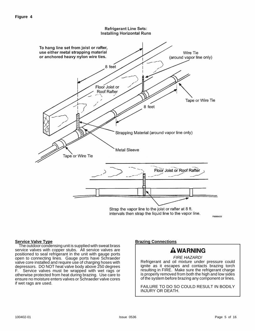
Installation Of Line SetsDO NOT fasten liquid or suction lines in direct contact
with the floor or ceiling joist. Use an insulated orsuspension type of hanger. Keep both lines separate, andalways insulate the suction line. Long liquid line runs (30feet or more) in an attic will require insulation. Routerefrigeration line sets to minimize length.
DO NOT let refrigerant lines come in direct contact withfoundation. When running refrigerant lines through thefoundation or wall, openings should allow for a sound andvibration absorbing material to be placed or installedbetween tubing and foundation. Any gap betweenfoundation or wall and refrigerant lines should be filled witha vibration damping material.
13 SEER A/C Piston SizesTonnage Piston Size
1.5 552 67
2.5 713 78
3.5 824 905 101
Line Set SizesUnit Size Liquid Line Vapor Line
18 3/8" 3/4"24 3/8" 3/430 3/8" 3/4"36 3/8" 3/4"42 3/8" 7/8"48 3/8" 7/8"60 3/8" 1-1/8" **
* 7/8" permissible, resulting in 3-4% capacity reduction
Liquid Line Size for A/CUnitSize
Approved Liquid Line Diameters up to:25 ft. 50 ft. 100 ft. 150 ft.
18 3/8" 3/8" 3/8" 3/8"24 3/8" 3/8" 3/8" 3/8"30 3/8" 3/8" 3/8" 3/8"
36 3/8" 3/8" 3/8" 3/8"1/2"
42 3/8" 3/8" 3/8"1/2"*
3/8"1/2"*
48 3/8" 3/8" 3/8" 1/2"60 3/8" 3/8" 3/8" 1/2"
Vapor Line Sizes for Outdoor SectionBelow Indoor Section
NominalUnit Size
Line Set Length up to . . . . 50 ft. 100 ft. 150 ft.
18 3/4" 3/4" 3/4"24 3/4" 3/4" 3/4"30 3/4" 3/4" 7/8"36 3/4" 7/8" 7/8"42 7/8" 7/8" 7/8"48 7/8" 1-1/8" 1-1/8"60 1-1/8" 1-1/8" 1-1/8"
Vapor Line Sizes for Outdoor Section AboveIndoor Section
NominalUnit Size
Line Set Length up to ....50 ft. 100 ft. 150 ft.
18 3/4" 3/4" 3/4"24 3/4" 3/4" 3/4"30 3/4" 3/4" 7/8"36 3/4" 3/4" 7/8"42 7/8" 7/8" 7/8"48 7/8" 7/8" 1-1/8"60 1-1/8" 1-1/8" 1-1/8"

100402-01 Issue 0536 Page 4 of 16
Figure 3
100402-01 Issue 0536 Page 5 of 16
Figure 4
Service Valve TypeThe outdoor condensing unit is supplied with sweat brass
service valves with copper stubs. All service valves arepositioned to seal refrigerant in the unit with gauge portsopen to connecting lines. Gauge ports have Schraedervalve core installed and require use of charging hoses withdepressors. DO NOT heat valve body above 250 degreesF. Service valves must be wrapped with wet rags orotherwise protected from heat during brazing. Use care toensure no moisture enters valves or Schraeder valve coresif wet rags are used.
Brazing Connections
FIRE HAZARD!Refrigerant and oil mixture under pressure couldignite as it escapes and contacts brazing torchresulting in FIRE. Make sure the refrigerant chargeis properly removed from both the high and low sidesof the system before brazing any component or lines.
FAILURE TO DO SO COULD RESULT IN BODILYINJURY OR DEATH.

100402-01 Issue 0536 Page 6 of 16
Before making sweat connections, be sure all joints areclean. Before heat is applied for brazing, dry nitrogenshould be flowing through the tubing to prevent oxidationand scale formation on the inside of the tubing.
The following is the recommended method for makingsweat connections at the refrigerant line connections:
1. Debur and clean refrigerant tube end with emerycloth or steel brush.
2. Insert tubing into swage fitting connection.3. Apply wet rags over valves or otherwise protect from
heat.3. Allow dry nitrogen to flow through refrigerant
pump.5. Braze joint, using a suitable brazing alloy for
copper to copper joints.6. Quench the joint and tubing with water using a wet
rag. Leave rag on fitting body and re—wet withwater to help cool area.
Leak CheckRefrigeration lines and indoor coil must be checked for
leaks after brazing and before evacuation. Therecommended procedure is to apply a trace amount ofvapor refrigerant (approximately two ounces or 3 psig) intothe line set and indoor coil, then pressurize with 150 psigof dry nitrogen. Use a refrigerant leak detector to check alljoints. The system may also be checked for leaks using ahalide torch or pressure and soapy solution. Aftercompletion of leak check, relieve all pressure from systembefore evacuation.
Evacuating And Charging InstructionsNOTE: Intentional release of CFC or HCFC refrigerant
to the atmosphere violates Federal Law. It mayalso violate State and Local Codes. Check allFederal, State and Local Codes beforeproceeding.
These outdoor units are pre-charged at the factory withadequate refrigerant to handle 15 feet of refrigerant tubing.
NOTE: DO NOT use any portion of the charge for purgingor leak testing. It is mandatory that a thoroughevacuation of the refrigeration lines and indoor coilbe performed.
The liquid line and suction line service valves have beenclosed after final testing at the factory. DO NOT disturbthese valves until the lines have been leak checked andevacuated or the charge in the unit may be lost.
1. Connect the vacuum pump to the center hose of themanifold gauge set, the low-pressure manifold gaugeto the vapor service valve and the high pressuremanifold gauge to the liquid service valve.
NOTE: Unnecessary switching of hoses can be avoidedand complete evacuation of all lines can beachieved by also connecting a branch hose fromthe manifold gauge center port to a cylinder of R-22. Provide a separate shut-off valve to vacuumpump to avoid contaminating vacuum pump oilwith refrigerant.
2. The valves should be kept in the "front seated"(closed) position. This will allow evacuation of the
refrigeration lines and the indoor coil, withoutdisturbing the factory charge in the outdoor unit.
3. Follow the vacuum pump manufacturer'sinstructions. Allow the pump to operate until thesystem has been evacuated down to 300 microns.Allow the pump to continue running for an additional15 minutes. Turn OFF the pump and leave theconnections secured to the two (2) service valves.After 5 minutes, if the system fails to hold 500microns or less, check all connections for tight fit andrepeat the evacuation procedure.
4. Isolate the vacuum pump from the system by closingthe shutoff valves on the gauge-set. Disconnect thevacuum pump.
Opening Service ValvesAfter evacuation of the connecting lines, remove the
service valve cap and fully insert the hex wrench into thestem. A back-up wrench is required on the valve body toopen the valve stem. Back-out counterclockwise until thevalve stem just touches the coined edge.
Wrench sizes:3/8 service valve: 3/16" Hex wrench3/4 service valve: 5/16" Hex wrench7/8 service valve: 5/16" Hex wrench
Replace service valve cap and torque to 8-11 ft-lb on 3/8"valves; 12-15 ft-lb on 3/4" valves; 15-20 ft-lb on 7/8" valves.Use backup wrench on valve body when torqueing valvecap.
Figure 5
NOTE: The cap is the primary seal and must be tightened to preventleaks.
Torque gauge port caps hand tight after adjusting chargeper "Adjusting Charge" section.

100402-01 Issue 0536 Page 7 of 16
Electrical Connections
Be sure to check all local codes to determine that the unitis installed accordance with local requirements. Consultthe National Electric Code for wire size requirements. Use60/ C wire or higher. Always provide ground connectionsto the outdoor unit. Power supply must agree with ratingon unit nameplate.
Provide line voltage power supply to unit from a properlysized disconnect switch. Route power and ground wiresfrom disconnect switch to unit. Line voltage connectionsare made at the line side of the contactor in the electricalbox of the condensing unit. Follow the appropriate wiringdiagram attached to inside of the access door of the unit.
Proper fusing recommendations are also indicated onUnit Rating Plate. In general, the best fuse for any unit isthe smallest fuse that will hold equipment on line undernormal use and service without nuisance tripping breakersor blowing of fuses. Time delay fuses are required toprevent blowing due to starting current (the current in rushwhen equipment starts is referred to as the Locked RotorAmps or (LRA). A fuse of this kind properly sized will givemaximum equipment protection.
Control WiringThe control voltage is 24 Vac. High quality insulated 18
AWG is recommended for control wiring. For lengthslonger than 150 feet, contact your local distributor fortechnical service.
Ensure room thermostat is properly installed perinstructions shipped with room thermostat. Generally,thermostat should not be exposed to sunlight, drafts orvibration and should not be mounted on exterior walls.
Low voltage control wire connections should be made asnoted on the wiring diagram on the inside cover of theoutdoor unit.
Figure 6
Pre-Start Procedure1. Check to ensure:
! service valve caps are installed and tightened! voltage supply at unit agrees with nameplate rating! all factory and field wiring connections are tight! indoor fan motor is on correct speed tap
2. Close electrical disconnects to energize system.
3. Energize crankcase heater, on units so equipped, for8 hours before operating the units.
Start-Up Procedure1. Set thermostat selector switch to OFF.
2. Set room thermostat at desired temperature. Be sureset point is below indoor ambient temperature.
3. Set the system switch of the thermostat on COOL andfan switch for continuous operation or AUTO, asdesired. Operate unit for a minimum of 10 minutes,then check the system refrigerant charge.
4. Adjust refrigerant charge per "Adjusting Charge"section.
Adjusting ChargeAll split system units are factory charged for 15 feet
of connecting line set and matched evaporator coil.Refrigerant charge should initially be adjusted for line setlengths other than 15 feet. For line sets shorter than 15feet in length, remove charge per Table 6. For line setslonger than 15 feet, add charge per Table 6. Oil charge issufficient for all line lengths.
Table 6
Final charge adjustments should be in the cooling modeby subcooling / superheat check, only when outdoorambient is above 60/F. If the outdoor ambient is below60/F, adjust charge only by weight and recheck later whenambient is above 60/F.
Before final adjustment is made to the refrigerant charge,it is imperative proper indoor airflow be established. Airflowwill be higher across a dry coil versus a wet coil. Blowercharts are usually calculated with a dry coil.Recommended airflow is 350-450 CFM per ton (12,000Btuh) through a wet coil. Refer to indoor unit instructionsfor methods of determining air flow and blowerperformance. To determine cfm flow in the field thefollowing calculation may be used:
ELECTRICAL SHOCK HAZARD!Turn OFF electric power before connecting unit,performing any maintenance or removing panels ordoors.
FAILURE TO DO SO COULD RESULT IN BODILYINJURY OR DEATH.
Refrigeration Charge AdjustmentLiquid Line Diameter Oz. Per Linear Foot *
3/8" .60
* Factory charge for series is for 15' (ft.) line sets and evaporatorcoil.

100402-01 Issue 0536 Page 8 of 16
Example:
(Electric Heat)VOLTS X AMPS X 3.414 BTUH/WATT = C.F.M. 1.08 X TEMP. DIFF.
(Fossil Fuel)BTUH OUTPUT = C.F.M.1.08 X TEMP. DIFF.
Piston System Charging1. Operate unit for minimum of 10 minutes (be sure
variable speed systems are at 100% fan speed).
2. Measure pressure and temperature at vapor valveservice port. Use a good thermistor or electronicthermometer.
3. Subtract saturation temperature (of measuredpressure) from temperature measured to obtainsuperheat. Refer to Table 8 for saturationtemperatures of R-22.
4. Measure outdoor dry bulb using a good thermometerand indoor wet bulb using a psychrometer.
5. Using measured temperatures, find closest outdoor drybulb and indoor wet bulb temperatures on appropriatecharging tables and locate required superheat. (Referto pages 10 - 12.)
6. If measured superheat is:! more than required, slowly add refrigerant to
obtain required superheat.! Less than required, slowly recover refrigerant to
obtain required superheat.
NOTE: Each time charge is added to or removed from thesystem, allow the system to run a minimum of 10minutes before pressure/temperature readings arere-taken and superheat calculations made.
TXV System Charging1. Operate unit for minimum of 10 minutes (be sure
variable speed systems are at 100% fan speed).
2. Measure pressure and temperature at liquid valveservice port. Use a good thermistor or electronicthermometer.
3. Subtract measured temperature from saturationtemperature (of measured pressure) measured toobtain subcooling. Refer to Table 8 for saturationtemperature of R-22.
4. The subcooling level should be 10-12/F subcooling.
5. If measured subcooling is:! more than required, slowly recover refrigerant to
obtain required subcooling.! less than required, slowly add refrigerant to obtain
required subcooling.
Unit MaintenanceThe unit should be inspected and cleaned on an annual
basis by a qualified technician. This should includechecking for adequate clearances, electrical connections,duct connections/blockages, air filters, airflow, lubrication,and operational performance of system. Coils mayrequire cleaning. The coil should always be cold whencleaning. Use an alkaline-based cleaner only.
Use of acidic cleaners will damage coil materialsand void manufacturers warranty.
Table 8R-22 Saturation Temperature / Pressure ChartPressure
(psig)Temp.
(/F)Pressure
(psig)Temp.
(/F)Pressure
(psig)Temp.
(/F)Pressure
(psig)Temp.
(/F)Pressure
(psig)Temp.
(/F)Pressure
(psig)Temp.
(/F)19.3 -6 31.8 9 44.1 21 58.8 33 76.0 45 155.7 8520.8 -4 32.8 10 45.3 22 60.1 34 77.6 46 168.4 9022.4 -2 33.7 11 46.4 23 61.5 35 79.2 47 181.8 9524.0 0 34.7 12 47.6 24 62.8 36 80.8 48 195.9 10024.8 1 35.7 13 48.8 25 64.2 37 82.4 49 210.8 10525.6 2 36.7 14 49.9 26 65.6 38 84.0 50 226.4 11026.4 3 37.7 15 51.2 27 67.1 39 92.6 55 242.7 11527.3 4 38.7 16 52.4 28 68.5 40 101.6 60 259.8 12028.2 5 39.8 17 53.6 29 70.0 41 111.2 65 277.8 12529.1 6 40.8 18 54.9 30 71.4 42 121.4 70 296.7 13030.0 7 41.9 19 56.2 31 73.0 43 132.2 75 316.5 13530.9 8 43.0 20 57.5 32 74.5 44 143.6 80 337.4 140

100402-01 Issue 0536 Page 9 of 16
A/C SINGLE PHASE WIRING DIAGRAM

100402-01 Issue 0536 Page 10 of 16
SUPERHEAT TABLES FOR CHARGING SYSTEMS WITH PISTON COILS
Required Superheat for 2AC13 (,L)18P-1A
Required Superheat for 2AC13(B,L)24P-1A
Required Superheat for 2AC13(B,L)30P-1A
INDOORWET-BULB
OUTDOOR DRY BULB TEMPERATURE50 55 60 65 70 75 80 85 80 95 100 105 110 115
53 6 4 3 -- -- -- -- -- -- -- -- -- -- --55 8 7 5 3 -- -- -- -- -- -- -- -- -- --57 11 9 7 6 4 2 -- -- -- -- -- -- -- --59 13 11 10 8 7 4 3 -- -- -- -- -- -- --61 15 14 12 10 9 7 5 3 -- -- -- -- -- --63 17 16 14 13 11 9 7 5 3 -- -- -- -- --65 19 18 16 15 14 11 10 7 5 3 -- -- -- --67 21 20 18 17 16 14 12 10 7 5 3 -- -- --69 23 22 20 19 18 16 14 12 10 7 6 4 2 --71 25 24 22 21 20 18 17 14 12 10 8 6 4 373 27 26 24 23 22 20 19 17 14 12 10 9 7 575 29 28 26 25 24 22 21 19 17 14 13 11 9 7
INDOORWET-BULB
OUTDOOR DRY BULB TEMPERATURE50 55 60 65 70 75 80 85 80 95 100 105 110 115
53 4 -- -- -- -- -- -- -- -- -- -- -- -- --55 8 5 2 -- -- -- -- -- -- -- -- -- -- --57 12 9 6 3 -- -- -- -- -- -- -- -- -- --59 16 13 10 7 5 -- -- -- -- -- -- -- -- --61 19 16 14 11 9 6 2 -- -- -- -- -- -- --63 22 20 17 15 13 10 6 2 -- -- -- -- -- --65 26 23 21 18 16 14 10 6 2 -- -- -- -- --67 29 27 24 22 19 17 14 10 6 2 -- -- -- --69 32 30 28 25 23 20 18 14 10 6 3 -- -- --71 35 33 31 29 26 24 21 18 14 10 7 4 -- --73 38 36 34 32 30 27 25 21 18 14 11 8 5 275 42 40 37 35 33 31 28 25 21 18 15 12 9 6
INDOORWET-BULB
OUTDOOR DRY BULB TEMPERATURE50 55 60 65 70 75 80 85 80 95 100 105 110 115
53 4 -- -- -- -- -- -- -- -- -- -- -- -- --55 7 4 2 -- -- -- -- -- -- -- -- -- -- --57 10 8 6 3 -- -- -- -- -- -- -- -- -- --59 14 11 9 7 4 -- -- -- -- -- -- -- -- --61 16 14 12 10 7 5 2 -- -- -- -- -- -- --63 19 17 15 13 11 8 5 2 -- -- -- -- -- --65 22 20 18 16 14 11 9 5 2 -- -- -- -- --67 25 23 21 19 17 15 12 9 5 2 -- -- -- --69 28 26 24 22 20 18 15 12 9 5 3 -- -- --71 31 29 27 25 23 21 18 15 12 9 6 4 -- --73 33 31 30 28 26 24 21 18 15 12 10 7 5 275 36 34 32 30 28 26 24 21 18 15 13 10 8 5

100402-01 Issue 0536 Page 11 of 16
Required Superheat for 2AC13(B,l)36p-1A
Required Superheat for 2AC13(B,L)42P-1A
Required Superheat for 2AC13(B,L)48P-1A
INDOORWET-BULB
OUTDOOR DRY BULB TEMPERATURE50 55 60 65 70 75 80 85 80 95 100 105 110 115
53 4 2 -- -- -- -- -- -- -- -- -- -- -- --55 7 5 3 -- -- -- -- -- -- -- -- -- -- --57 9 8 6 4 2 -- -- -- -- -- -- -- -- --59 12 10 8 6 5 2 -- -- -- -- -- -- -- --61 15 13 11 9 7 5 3 -- -- -- -- -- -- --63 17 15 14 12 10 8 6 3 -- -- -- -- -- --65 19 18 16 14 13 10 8 6 3 -- -- -- -- --67 21 20 18 17 15 13 11 8 6 3 -- -- -- --69 24 22 20 19 17 16 14 11 8 6 4 -- -- --71 26 24 23 21 20 18 16 14 11 8 6 4 2 --73 28 27 25 23 22 20 19 16 14 11 9 7 5 375 30 29 27 26 24 23 21 19 16 14 12 10 8 6
INDOORWET-BULB
OUTDOOR DRY BULB TEMPERATURE50 55 60 65 70 75 80 85 80 95 100 105 110 115
53 4 -- -- -- -- -- -- -- -- -- -- -- -- --55 9 6 3 -- -- -- -- -- -- -- -- -- -- --57 13 10 7 4 -- -- -- -- -- -- -- -- -- --59 17 14 12 8 5 -- -- -- -- -- -- -- -- --61 20 18 15 13 9 6 4 -- -- -- -- -- -- --63 24 22 19 16 14 11 8 3 -- -- -- -- -- --65 28 26 23 20 17 15 12 7 3 -- -- -- -- --67 31 29 26 24 21 19 16 12 7 3 -- -- -- --69 35 32 30 28 25 22 20 16 12 7 4 -- -- --71 38 36 34 31 29 26 23 20 16 12 8 5 2 --73 42 39 37 35 32 30 27 23 20 16 13 10 6 375 45 43 40 38 35 33 31 27 23 20 16 13 10 7
INDOORWET-BULB
OUTDOOR DRY BULB TEMPERATURE50 55 60 65 70 75 80 85 80 95 100 105 110 115
53 4 -- -- -- -- -- -- -- -- -- -- -- -- --55 8 5 -- -- -- -- -- -- -- -- -- -- -- --57 13 10 7 3 -- -- -- -- -- -- -- -- -- --59 17 14 11 8 4 -- -- -- -- -- -- -- -- --61 21 18 15 12 9 5 3 -- -- -- -- -- -- --63 25 22 19 16 14 10 7 2 -- -- -- -- -- --65 29 26 23 20 18 15 12 7 2 -- -- -- -- --67 33 30 27 24 22 19 16 11 7 2 -- -- -- --69 36 34 31 28 26 23 20 16 11 7 3 -- -- --71 40 37 35 32 30 27 24 20 16 11 8 4 -- --73 44 41 39 36 33 31 28 24 20 16 13 9 6 275 47 45 42 39 37 34 32 28 24 20 17 13 10 6

100402-01 Issue 0536 Page 12 of 16
Required Superheat for 2AC13(B,L)60P-1AINDOOR
WET-BULBOUTDOOR DRY BULB TEMPERATURE
50 55 60 65 70 75 80 85 80 95 100 105 110 11553 5 2 -- -- -- -- -- -- -- -- -- -- -- --55 10 7 3 -- -- -- -- -- -- -- -- -- -- --57 15 12 8 4 -- -- -- -- -- -- -- -- -- --59 19 16 13 9 6 2 -- -- -- -- -- -- -- --61 23 20 17 14 11 7 4 -- -- -- -- -- -- --63 27 25 22 18 15 12 9 3 -- -- -- -- -- --65 31 29 26 23 20 17 14 8 3 -- -- -- -- --67 35 33 30 27 24 21 18 13 8 3 -- -- -- --69 39 37 34 31 28 25 22 18 13 8 4 -- -- --71 43 41 38 35 32 30 27 22 18 13 9 6 -- --73 47 45 42 39 36 34 31 27 22 18 14 11 7 375 51 48 46 43 40 37 35 31 27 22 19 15 11 7

100402-01 Issue 0536 Page 13 of 16
Home Owner's Information
AIR CONDITIONINGRoom Thermostat
The wall-mounted thermostat controls your airconditioner. The thermostat is available in variousconfigurations from different manufacturers. Theinformation below is typical for most thermostats. Ask yourdealer for specific information regarding the model ofthermostat installed.
For Cooling Cycle switch the room thermostat systemlever to "Cool". The thermostat will turn the air conditioneron in the cooling mode until the selected room temperatureis achieved and then shut off automatically.
Some room thermostats have a setting on the systemlever marked "AUTO" which will automatically changebetween heating and cooling modes.
NOTE: Some heating and cooling units have a resetfeature which will allow you to reset the unit at thethermostat after some abnormal condition hascaused safety switches to cut the unit off. If yourunit has this feature, switch the system lever toOFF and back to COOL or HEAT. If you are indoubt which model you have, please consult yourDealer.
For Fan Control your thermostat may have a FanSelection Switch that allows you to run the fan continuouslyor cycle it automatically with the heating or cooling system.Switch the lever to ON for continuous operation and toAUTO for automatic cycling.
For maximum comfort satisfaction and continual aircleaning/filtering, constant fan operation is recommended.
On models without a Fan Selection Switch, the fan willcycle with the outdoor unit.
Important System Information! Your system should never be operated without a
clean air filter properly installed.
! Return air and supply air registers should be freefrom restrictions or obstructions to allow full flow ofair.
! Air conditioners remove humidity from your home.Depending on the amount of moisture in the airinside your home, water will trickle from thecondensate drain of the indoor cooling coil.
Regular Maintenance RequirementsYour system should be regularly inspected by a qualified
service technician. These regular visits may include(among other things) checks for:! motor operation! ductwork air leaks! coil & drainpan cleanliness (indoor & outdoor)! electrical component operation & wiring check! proper refrigerant level & refrigerant leaks! proper airflow! drainage of condensate! air filter(s) performance! blower wheel alignment, balance & cleaning primary
and secondary drain line cleanliness
There are some routine maintenance procedures you cando to help keep your system operating at peakperformance. Additional maintenance or service must beperformed by a qualified service personal.
Air FilterInspect air filters at least monthly and replace or clean as
required. Disposable filters should be replaced. Washablefilters may be cleaned by soaking in mild detergent andrinsing with cold water. Replace filters with the arrowspointing in the direction of airflow. Dirty filters are the mostcommon cause of poor cooling performance andcompressor failures.
Indoor CoilIf the system has been operated with a clean filter in
place, it should require minimal cleaning. Use a vacuumcleaner and soft brush attachment to remove anyaccumulation of dust from the top and underside of thefinned coil surface. However, perform this maintenanceonly when the coil is completely dry.
If the coil cannot be cleaned by this method, call yourdealer for service. It may need a detergent solution andrinsing with water for cleaning, which may require coilremoval. You should not attempt this yourself.
Condensate DrainDuring cooling season check at least monthly for free
flow of drainage and clean if necessary.
Condenser CoilsGrass cuttings, leaves, dirt, dust, lint from clothes dryers,
and fall off from trees can be drawn into coils by movementof the air. Clogged condenser coils will lower the efficiencyof your unit and could cause damage to the condenser.Periodically, debris should be brushed from the condensercoils.
ELECTRICAL SHOCK HAZARD!Turn OFF electric power to unit before performingany maintenance or removing panels or doors.
FAILURE TO DO SO COULD RESULT IN BODILYINJURY OR DEATH.
SHARP OBJECT HAZARD!Condenser coils have sharp edges. Wear adequatebody protection on body extremities (e.g. gloves).Failure to follow this warning could result in bodilyinjury.

100402-01 Issue 0536 Page 14 of 16
Use a soft bristle brush with light pressure only. DO NOTdamage or bend condenser coil fins. Damaged or bent finsmay affect unit operation.
Painted SurfacesFor maximum protection of the unit's finish, a good grade
of automobile wax should be applied every year. Ingeographical areas where water has a high concentrationof minerals (calcium, iron, sulfur, etc.), it is recommendedthat lawn sprinklers not be allowed to spray the unit. Insuch applications, the sprinklers should be directed awayfrom the unit. Failure to follow this precaution may result inpremature deterioration of the unit finish and metalcomponents.
In sea coastal areas, special maintenance is requireddue to the corrosive atmosphere provided by the high saltconcentration in ocean mists and the air. Periodic washingof all exposed surfaces and coil will add additional life toyour unit. Please consult your installing dealer for properprocedures in your geographic area.
Units should be positioned to avoid contact with pet orlivestock traffic.
1. Ensure thermostat is set below (cooling) or above(heating) room temperature and that the system leveris in the "COOL", "HEAT" or "AUTO" position.
2. Inspect your return air filter: If it is dirty your airconditioner may not function properly.
3. Check indoor and outdoor disconnect switches.Confirm circuit breakers are ON or that fuses have notblown. Reset breakers/replace fuses as necessary.
4. Inspect the outdoor unit for clogged condenser coils,(grass cuttings, leaves, dirt, dust or lint). Ensure thatbranches, twigs or other debris are not obstructing thecondenser fan.
IF YOUR SYSTEM STILL DOES NOT OPERATE,CONTACT YOU SERVICING DEALER.
Be sure to describe the problem, and have the modeland serial numbers of the equipment available.
IF YOUR SYSTEM DOES NOT WORK,BEFORE REQUESTING A SERVICE CALL:

100402-01 Issue 0536 Page 15 of 16
OUTDOOR EQUIPMENT LIMITED WARRANTY(Not applicable outside the U.S.A. and Canada.)
GENERAL FIVE YEAR PART WARRANTY - The manufacturer warrants the product to be free from defects in materialand workmanship under normal use and maintenance for a period of five (5) years in residential applications (one (1)year for commercial) on all components. The warranty period begins on the date of original installation whether or notactual use begins on that date. If the date of original installation cannot be verified, the warranty begins on the date ofmanufacture plus six (6) months. At the Manufacturer’s sole option, a new or re-manufactured part to replace anydefective part will be provided without charge for the part itself; PROVIDED the defective part is returned to our distributorthrough a qualified servicing dealer or contractor. The replacement part assumes the unused portion of the factorywarranty. Residential application is defined as a single family or multi-family dwelling.
COVERED PARTS INCLUDE - compressor, capacitor, condenser coil, contactor, fan blade, fan motor, muffler, servicevalve, solenoid valve, unit mounted sensors and switches, if present.
2AC13 FIVE YEAR COMPRESSOR WARRANTY - The compressor in this is warranted to be free from defects inmaterial and workmanship under normal use and maintenance for a period of five (5) years. The compressor will beprovided without charge for the compressor itself; PROVIDED the defective compressor is returned to our distributorthrough a qualified servicing dealer or contractor. The replacement compressor assumes the unused portion of thefactory warranty.
THIS WARRANTY DOES NOT INCLUDE LABOR OR OTHER COSTS incurred for diagnosing, repairing, removing,installing, shipping, servicing, or handling of either defective parts or replacement parts or complete unit. Other costsnot covered include items such as any materials not listed above, refrigerant and refrigerant reclaiming. Such costs maybe covered by a separate warranty provided by the installing dealer or contractor.
THESE WARRANTIES APPLY ONLY:- To products in their original installation location and become void upon re-installation.- To units installed with indoor coil combinations listed in the Air-Conditioning and Refrigeration Institute (ARI)
Directory of Certified Unitary Equipment. (www.ARIPrimenet.org.)
EXCEPTIONS TO LIMITED WARRANTY - When the outdoor unit is installed in non-residential applications; thecompressor is warranted for 1 year.
LIMITATIONS OF WARRANTIES - All implied warranties (including implied warranties of merchantability) are herebylimited in duration to the period for which the limited warranty is given. Some states do not allow limitations on how longan implied warranty lasts, so the above may not apply to you. The expressed warranties made in this warranty areexclusive and may not be altered, enlarged, or changed by any distributor, dealer, contractor or other person whatsoever.
THE MANUFACTURER WILL NOT BE RESPONSIBLE FOR: 1. Failure to start due to voltage conditions, blown fuses, open circuit breakers or other damages due to the inadequacy
or interruption of electrical service;2. Damage as a result of floods, winds, fires, lightning, accidents, corrosive environments or other conditions beyond
the control of the Manufacturer;3. Damage or repairs required as a consequence of faulty installation, misapplication, abuse, improper servicing,
unauthorized alteration or improper operation;4. Normal maintenance as outlined in the installation and servicing instructions or owner's manual including coil
cleaning, filter cleaning and/or replacement and lubrication;5. Parts not supplied or designated by the Manufacturer, or damages resulting from their use;6. The Manufacturer products installed outside the United States of America and Canada;7. Electricity or fuel costs or increases in electricity or fuel costs for any reason whatsoever including additional or
unusual use of supplemental electric heat;8. ANY SPECIAL INDIRECT OR CONSEQUENTIAL PROPERTY OR COMMERCIAL DAMAGE OF ANY NATURE
WHATSOEVER. Some states do not allow the exclusion of incidental or consequential damages, so the abovelimitation may not apply to you.
This warranty gives you specific rights, and you may also have other rights that vary from state to state.

100402-01 Issue 0536 Page 16 of 16
Keep this book and your sales slip together for future reference. You must provide proof of purchase or installationdate for in-warranty service.
Write down the following information about your unit to better help you obtain assistance or service if you ever need it. Youwill need to know the complete model and serial number. You can find this information on the unit rating plate.
Dealer Name:
Address:
Phone Number:
Model Number:
Serial Number:
Installation Date: