
SPK 210/240 TPK 300/500 High Performance Hypoid gearboxes · Contents 4 SPK+ 8 SPK+ 210, technical...
36
alpha SPK + 210/240 TPK + 300/500 High Performance Hypoid gearboxes powerful precise efficient
Transcript of SPK 210/240 TPK 300/500 High Performance Hypoid gearboxes · Contents 4 SPK+ 8 SPK+ 210, technical...

alpha
SPK+ 210/240 TPK+ 300/500
High Performance Hypoid gearboxes
powerfulpreciseeffi cient


Contents 4
SPK+ 8
SPK+ 210, technical and dimension data 8
SPK+ 240, technical and dimension data 12
TPK+ 18
TPK+ 300, technical and dimension data 18
TPK+ 500, technical and dimension data 22
TPK+ (High Torque) 28
TPK+ 110, technical and dimension data 28
TPK+ 300, technical and dimension data 30
TPK+ 500, technical and dimension data 32
Ordering code 34

The SPK+/TPK+ High Performance Hypoid gearboxes
Powerful products in the new hypoid range
To guarantee the highest possible productivity of your machine, WITTENSTEIN alpha has enhanced the range of hypoid planetary gearboxes. The newly developed bevel gears are derived from modern hypoid technology in combination with planetary gears with helical gearing. The result is the creation of the best product for maximized performance. With extremely high torque and high ratios we set new standards in the bevel gear market.
WITTENSTEIN alpha moves your world into new dimensions!
Shaft and fl ange output ·Torques up to 10000 Nm ·Ratios up to i=10000 ·Effi ciency of up to 94 % ·Low noise emission · ≤ 71 dB(A)High turning torque available up to 9500 Nm ·
Highest positioning accuracy with less torsion play ·and high torsional rigidityOptimized seal technology (IP65) ·Flexible position of installation ·Very high input speed up to 4500 rpm ·
SPK+/TPK+ High Performance Hypoid gearboxes
All features at a glance:

10000
8000
6000
4000
2000
010075
025100
050140
110180
300210
500240
SPK+
TPK+
TPK+ High Torque
TPK+
SPK+
TPK+
SPK+
010075
025100
050140
110180
300210
500240
SPK+ T2B Nm 110 300 600 1100 2500 4500
TPK+ T2B Nm 130 350 750 1600 3300 6000
TPK+ High Torque T2B Nm – – – 3100 5500 10000
New sizes
WITTENSTEIN alpha moves your world into new dimensions!
ma
x.
ac
ce
lera
tio
n m
om
en
t
Past sizes (see union catalog)
Size
Size
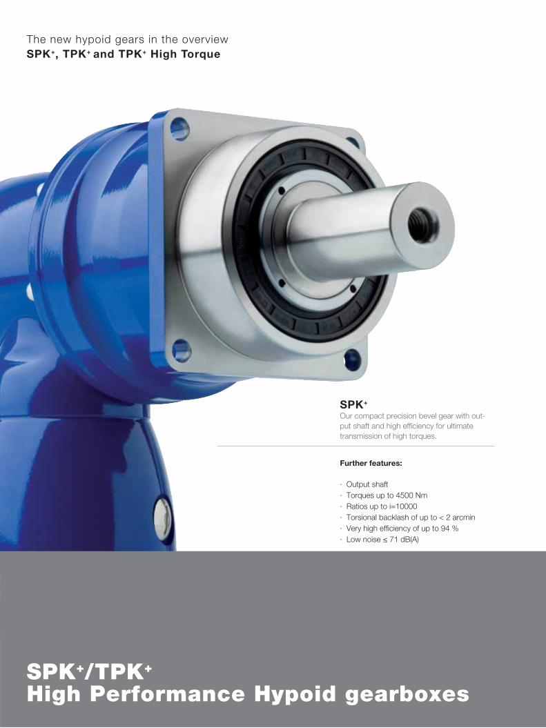
SPK+ Our compact precision bevel gear with out-put shaft and high effi ciency for ultimatetransmission of high torques.
The new hypoid gears in the overviewSPK+, TPK+ and TPK+ High Torque
Further features:
Output shaft ·Torques up to 4500 Nm ·Ratios up to i=10000 ·Torsional backlash of up to < 2 arcmin ·Very high effi ciency of up to 94 % ·Low noise · ≤ 71 dB(A)
SPK+/TPK+ High Performance Hypoid gearboxes

TPK+ Our compact precision bevel gear with output fl ange and high effi ciency for transmission of high torques.
TPK+ High TorqueOur power packet for highest positioning accuracy combines highest torques and torsional rigidity with the compactness of a bevel gear
Further features:
Output fl ange for high torsional rigidity ·Torques of up to 6000 Nm ·Ratios up to i=10000 ·Torsional backlash of up to < 2 arcmin ·Very high effi ciency of up to 94 % ·Very high quietness · ≤ 71 dB(A)
Further features:
Output fl ange ·Torques of up to 10000 Nm ·Ratios of up to i=5500 ·Torsional backlash of up to < 1,3 arcmin ·High tilting moment of up to 9500 Nm ·Highest positioning accuracy ·Highest power density ·

8
12 16 20 25 28 35 40 50 70 100
2500 2500 2500 2500 2400 2400 1850 2300 2400 1900
1500 1500 1500 1500 1400 1500 1400 1500 1400 1000
3600 4200 5200 5200 5200 5200 3600 4500 5200 5000
1500 1700 1700 1900 1700 1900 1700 1700 1700 1700
1900 2300 2300 2700 2300 2700 2400 2400 2400 2400
4000 4000 4000 4000 4000 4000 4000 4000 4000 4000
18,5 17,0 15,0 13,0 14,0 12,0 15,0 15,0 14,0 13,0
300 300 300 300 300 300 300 300 300 300
30000
21000
3100
94
> 20000
–
≤ 71
+90
M 48 78,80 54,60 53,00 43,40 51,50 42,20 30,20 30,00 29,80 29,80
SPK+ 210 MF 2-stage
2-stage
Ratio a) i
Max. acceleration torque(max. 1000 cycles per hour)
T2B Nm
Nominal output torque(with n1N )
T2N Nm
Emergency stop torque(permitted 1000 times during the service life of the gearhead)
T2Not Nm
Nominal input speed(with T2N and 20°C ambient temperature) b), c) n1N rpm
Max. continuous speed(with 20 % T2N and 20°C ambient temperature)
n1Ncym rpm
Max. input speed n1Max rpm
Mean no load running torque(with n1 = 3000 rpm and 20°C gearhead temperature) d) T012 Nm
Max. torsional backlash jt arcmin Standard ≤4 / Reduced ≤2
Torsional rigidity Ct21 Nm/arcmin
Max. axial force e) F2AMax N
Max. radial force e) F2RMax N
Max. tilting moment M2KMax Nm
Efficiency at full load η %
Service life(For calculation, see the Chapter “Information”)
Lh h
Weight incl. standard adapter plate m kg
Operating noise(with n1 = 3000 rpm no load)
LPA dB(A)
Max. permitted housing temperature °C
Ambient temperature °C 0 to +40
Lubrication Lubricated for life
Paint Blue RAL 5002
Direction of rotation Motor and gearhead opposite directions
Protection class IP 65
Moment of inertia(relates to the drive)
Clamping hub diameter [mm]J1 kgcm2
a) Other ratios available on requestb) Higher speeds are possible if the nominal torque is reducedc) For higher ambient temperatures, please reduce input speedd) Idling torques decrease during operation e) Refers to center of the output shaft or flange
Please contact us for information on the best configuration for S1 conditions of use (continuous operation).

9
A2-stage:
View A
Non-tolerated dimensions ±1 mm
1) Check motor shaft fit.
2) Min./Max. permissible motor shaft length. Longer motor shafts are
adaptable, please contact us.
3) The dimensions depend on the motor.
4) Smaller motor shaft diameter is compensated by a bushing with
a minimum thickness of 1 mm.
Motor mounting according to operating manual!
See technical data sheet for available clamping hub diameters
(mass moment of inertia). Dimensions available on request.
10
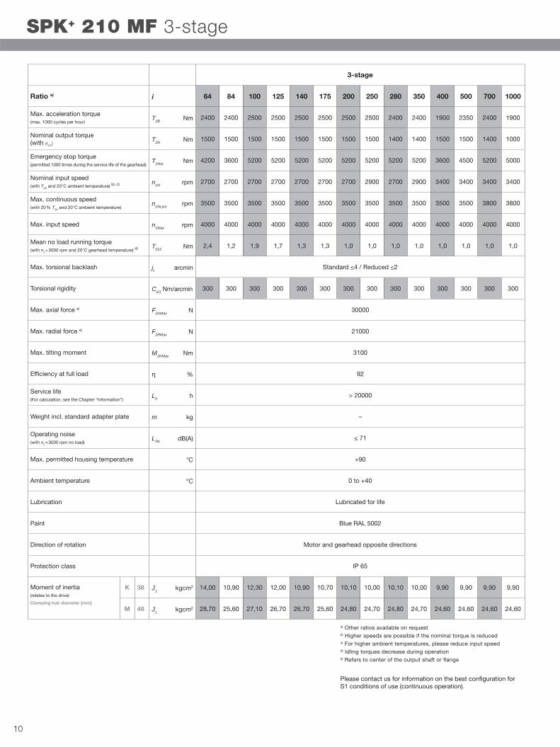
64 84 100 125 140 175 200 250 280 350 400 500 700 1000
2400 2400 2500 2500 2500 2500 2500 2500 2400 2400 1900 2350 2400 1900
1500 1500 1500 1500 1500 1500 1500 1500 1400 1400 1500 1500 1400 1000
4200 3600 5200 5200 5200 5200 5200 5200 5200 5200 3600 4500 5200 5000
2700 2700 2700 2700 2700 2700 2700 2900 2700 2900 3400 3400 3400 3400
3500 3500 3500 3500 3500 3500 3500 3500 3500 3500 3500 3500 3800 3800
4000 4000 4000 4000 4000 4000 4000 4000 4000 4000 4000 4000 4000 4000
2,4 1,2 1,9 1,7 1,3 1,3 1,0 1,0 1,0 1,0 1,0 1,0 1,0 1,0
300 300 300 300 300 300 300 300 300 300 300 300 300 300
30000
21000
3100
92
> 20000
–
≤ 71
+90
K 38 14,00 10,90 12,30 12,00 10,90 10,70 10,10 10,00 10,10 10,00 9,90 9,90 9,90 9,90
M 48 28,70 25,60 27,10 26,70 26,70 25,60 24,80 24,70 24,80 24,70 24,60 24,60 24,60 24,60
3-stage
Ratio a) i
Max. acceleration torque(max. 1000 cycles per hour)
T2B Nm
Nominal output torque(with n1N )
T2N Nm
Emergency stop torque(permitted 1000 times during the service life of the gearhead)
T2Not Nm
Nominal input speed(with T2N and 20°C ambient temperature) b), c) n1N rpm
Max. continuous speed(with 20 % T2N and 20°C ambient temperature)
n1Ncym rpm
Max. input speed n1Max rpm
Mean no load running torque(with n1 = 3000 rpm and 20°C gearhead temperature) d) T012 Nm
Max. torsional backlash jt arcmin Standard ≤4 / Reduced ≤2
Torsional rigidity Ct21 Nm/arcmin
Max. axial force e) F2AMax N
Max. radial force e) F2RMax N
Max. tilting moment M2KMax Nm
Efficiency at full load η %
Service life(For calculation, see the Chapter “Information”)
Lh h
Weight incl. standard adapter plate m kg
Operating noise(with n1 = 3000 rpm no load)
LPA dB(A)
Max. permitted housing temperature °C
Ambient temperature °C 0 to +40
Lubrication Lubricated for life
Paint Blue RAL 5002
Direction of rotation Motor and gearhead opposite directions
Protection class IP 65
Moment of inertia(relates to the drive)
Clamping hub diameter [mm]
J1 kgcm2
J1 kgcm2
SPK+ 210 MF 3-stage
a) Other ratios available on requestb) Higher speeds are possible if the nominal torque is reducedc) For higher ambient temperatures, please reduce input speedd) Idling torques decrease during operation e) Refers to center of the output shaft or flange
Please contact us for information on the best configuration for S1 conditions of use (continuous operation).

11
A3-stage:
View A
Non-tolerated dimensions ±1 mm
1) Check motor shaft fit.
2) Min./Max. permissible motor shaft length. Longer motor shafts are
adaptable, please contact us.
3) The dimensions depend on the motor.
4) Smaller motor shaft diameter is compensated by a bushing with
a minimum thickness of 1 mm.
Motor mounting according to operating manual!
See technical data sheet for available clamping hub diameters
(mass moment of inertia). Dimensions available on request.
12
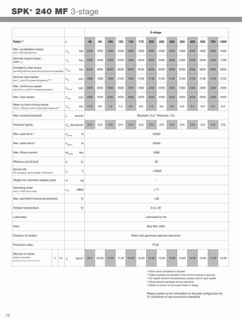
48 64 100 125 140 175 200 250 280 350 400 500 700 1000
4500 4500 4500 4500 4500 4500 4500 4500 4300 4500 4000 4300 4300 3400
2500 2500 2500 2500 2500 2500 2500 2500 2300 2500 2500 2500 2300 1700
6400 8000 8500 8500 8500 8500 8500 8500 8500 8500 8500 8500 8500 6800
1800 1900 1900 2100 1900 2100 2100 2100 2100 2100 2100 2100 2100 2100
2000 2200 2600 2600 2300 2300 2300 2300 2300 2300 2300 2300 2300 2300
4500 4500 4500 4500 4500 4500 4500 4500 4500 4500 4500 4500 4500 4500
11,0 8,0 7,0 7,0 8,0 8,0 7,0 6,0 6,0 6,0 6,0 6,0 6,0 6,0
510 510 510 510 510 510 510 510 510 510 510 510 510 510
33000
30000
5000
92
> 20000
–
≤ 71
+90
K 38 26,5 20,00 17,00 17,00 15,00 15,00 13,00 13,00 13,00 13,00 13,00 13,00 13,00 13,00
3-stage
Ratio a) i
Max. acceleration torque(max. 1000 cycles per hour)
T2B Nm
Nominal output torque(with n1N )
T2N Nm
Emergency stop torque(permitted 1000 times during the service life of the gearhead)
T2Not Nm
Nominal input speed(with T2N and 20°C ambient temperature) b), c) n1N rpm
Max. continuous speed(with 20 % T2N and 20°C ambient temperature)
n1Ncym rpm
Max. input speed n1Max rpm
Mean no load running torque(with n1 = 3000 rpm and 20°C gearhead temperature) d) T012 Nm
Max. torsional backlash jt arcmin Standard ≤ 5,5 / Reduced ≤ 3,5
Torsional rigidity Ct21 Nm/arcmin
Max. axial force e) F2AMax N
Max. radial force e) F2RMax N
Max. tilting moment M2KMax Nm
Efficiency at full load η %
Service life(For calculation, see the Chapter “Information”)
Lh h
Weight incl. standard adapter plate m kg
Operating noise(with n1 = 3000 rpm no load)
LPA dB(A)
Max. permitted housing temperature °C
Ambient temperature °C 0 to +40
Lubrication Lubricated for life
Paint Blue RAL 5002
Direction of rotation Motor and gearhead opposite directions
Protection class IP 65
Moment of inertia(relates to the drive)
Clamping hub diameter [mm]J1 kgcm2
SPK+ 240 MF 3-stage
a) Other ratios available on requestb) Higher speeds are possible if the nominal torque is reducedc) For higher ambient temperatures, please reduce input speedd) Idling torques decrease during operation e) Refers to center of the output shaft or flange
Please contact us for information on the best configuration for S1 conditions of use (continuous operation).

13
A3-stage:
View A
Non-tolerated dimensions ±1 mm
1) Check motor shaft fit.
2) Min./Max. permissible motor shaft length. Longer motor shafts are
adaptable, please contact us.
3) The dimensions depend on the motor.
4) Smaller motor shaft diameter is compensated by a bushing with
a minimum thickness of 1 mm.
Motor mounting according to operating manual!
See technical data sheet for available clamping hub diameters
(mass moment of inertia). Dimensions available on request.

14
144 192 256 300 375 420 500 560 600 700 800 875 1000
4500 4500 4500 4500 4500 4500 4500 4500 4500 4500 4500 4500 4500
2500 2500 2500 2500 2500 2500 2500 2500 2500 2500 2500 2500 2500
8000 8000 8000 8500 8500 8500 8500 8500 8500 8500 8500 8500 8500
2700 2900 2900 2900 2900 2900 2900 2900 2900 2900 2900 2900 3200
3800 4000 4000 4000 4000 4000 4000 4000 4000 4000 4000 4000 4200
4500 4500 4500 4500 4500 4500 4500 4500 4500 4500 4500 4500 4500
3,2 2,3 1,6 1,3 0,7 0,9 0,9 0,8 0,7 0,7 0,6 0,6 0,5
510 510 510 510 510 510 510 510 510 510 510 510 510
33000
30000
5000
90
> 20000
–
≤ 71
+90
G 24 5,96 4,30 3,90 3,32 3,31 2,80 3,18 2,80 2,49 2,73 2,49 2,73 2,46
K 38 12,87 11,19 10,81 10,23 10,22 9,72 10,09 9,71 9,40 9,65 9,40 9,65 9,37
4-stage
Ratio a) i
Max. acceleration torque(max. 1000 cycles per hour)
T2B Nm
Nominal output torque(with n1N )
T2N Nm
Emergency stop torque(permitted 1000 times during the service life of the gearhead)
T2Not Nm
Nominal input speed(with T2N and 20°C ambient temperature) b), c) n1N rpm
Max. continuous speed(with 20 % T2N and 20°C ambient temperature)
n1Ncym rpm
Max. input speed n1Max rpm
Mean no load running torque(with n1 = 3000 rpm and 20°C gearhead temperature) d) T012 Nm
Max. torsional backlash jt arcmin Standard ≤ 5,5 / Reduced ≤ 3,5
Torsional rigidity Ct21 Nm/arcmin
Max. axial force e) F2AMax N
Max. radial force e) F2RMax N
Max. tilting moment M2KMax Nm
Efficiency at full load η %
Service life(For calculation, see the Chapter “Information”)
Lh h
Weight incl. standard adapter plate m kg
Operating noise(with n1 = 3000 rpm no load)
LPA dB(A)
Max. permitted housing temperature °C
Ambient temperature °C 0 to +40
Lubrication Lubricated for life
Paint Blue RAL 5002
Direction of rotation Motor and gearhead opposite directions
Protection class IP 65
Moment of inertia(relates to the drive)
Clamping hub diameter [mm]
J1 kgcm2
J1 kgcm2
SPK+ 240 MF 4-stage i=144-1000
a) Other ratios available on requestb) Higher speeds are possible if the nominal torque is reducedc) For higher ambient temperatures, please reduce input speedd) Idling torques decrease during operation e) Refers to center of the output shaft or flange
Please contact us for information on the best configuration for S1 conditions of use (continuous operation).

15
A4-stage:
View A
Non-tolerated dimensions ±1 mm
1) Check motor shaft fit.
2) Min./Max. permissible motor shaft length. Longer motor shafts are
adaptable, please contact us.
3) The dimensions depend on the motor.
4) Smaller motor shaft diameter is compensated by a bushing with
a minimum thickness of 1 mm.
Motor mounting according to operating manual!
See technical data sheet for available clamping hub diameters
(mass moment of inertia). Dimensions available on request.

16
1225 1400 1750 2000 2800 3500 5000 7000 10000
4500 4500 4500 4200 4300 4500 4300 4300 3400
2500 2500 2500 2500 2300 2500 2500 2300 1700
8500 8500 8500 8000 8500 8500 8500 8500 6800
2900 2900 3200 3900 3900 3900 3900 3900 3900
4000 4000 4200 4200 4200 4200 4200 4200 4200
4500 4500 4500 4500 4500 4500 4500 4500 4500
0,6 0,6 0,4 0,4 0,4 0,4 0,4 0,3 0,3
510 510 510 510 510 510 510 510 510
33000
30000
5000
90
> 20000
–
≤ 71
+90
G 24 2,73 2,49 2,46 2,42 2,42 2,42 2,42 2,42 2,42
K 38 9,64 9,40 9,37 9,33 9,33 9,33 9,33 9,33 9,33
4-stage
Ratio a) i
Max. acceleration torque(max. 1000 cycles per hour)
T2B Nm
Nominal output torque(with n1N )
T2N Nm
Emergency stop torque(permitted 1000 times during the service life of the gearhead)
T2Not Nm
Nominal input speed(with T2N and 20°C ambient temperature) b), c) n1N rpm
Max. continuous speed(with 20 % T2N and 20°C ambient temperature)
n1Ncym rpm
Max. input speed n1Max rpm
Mean no load running torque(with n1 = 3000 rpm and 20°C gearhead temperature) d) T012 Nm
Max. torsional backlash jt arcmin Standard ≤ 5,5 / Reduced ≤ 3,5
Torsional rigidity Ct21 Nm/arcmin
Max. axial force e) F2AMax N
Max. radial force e) F2RMax N
Max. tilting moment M2KMax Nm
Efficiency at full load η %
Service life(For calculation, see the Chapter “Information”)
Lh h
Weight incl. standard adapter plate m kg
Operating noise(with n1 = 3000 rpm no load)
LPA dB(A)
Max. permitted housing temperature °C
Ambient temperature °C 0 to +40
Lubrication Lubricated for life
Paint Blue RAL 5002
Direction of rotation Motor and gearhead opposite directions
Protection class IP 65
Moment of inertia(relates to the drive)
Clamping hub diameter [mm]
J1 kgcm2
J1 kgcm2
SPK+ 240 MF 4-stage i=1225-10000
a) Other ratios available on requestb) Higher speeds are possible if the nominal torque is reducedc) For higher ambient temperatures, please reduce input speedd) Idling torques decrease during operation e) Refers to center of the output shaft or flange
Please contact us for information on the best configuration for S1 conditions of use (continuous operation).

17
A4-stage:
View A
Non-tolerated dimensions ±1 mm
1) Check motor shaft fit.
2) Min./Max. permissible motor shaft length. Longer motor shafts are
adaptable, please contact us.
3) The dimensions depend on the motor.
4) Smaller motor shaft diameter is compensated by a bushing with
a minimum thickness of 1 mm.
Motor mounting according to operating manual!
See technical data sheet for available clamping hub diameters
(mass moment of inertia). Dimensions available on request.

18
15 20 25 35 49 50 70 100
3200 3200 3200 3300 3300 2350 3300 2800
2000 2000 2000 1800 1800 1800 1800 1600
4500 5250 5250 7350 6800 4500 6300 8750
1500 1700 1900 1900 1700 1700 1700 1700
1900 2300 2700 2700 2400 2400 2400 2400
4000 4000 4000 4000 4000 4000 4000 4000
18,5 15,0 13,0 12,0 12,0 15,0 14,0 13,0
615 640 664 730 728 658 727 642
33000
5900
94
> 20000
–
≤ 71
+90
M 48 74,00 52,00 43,00 43,00 35,00 30,00 30,00 30,00
TPK+ 300 MF 2-stage
2-stage
Ratio a) i
Max. acceleration torque(max. 1000 cycles per hour)
T2B Nm
Nominal output torque(with n1N )
T2N Nm
Emergency stop torque(permitted 1000 times during the service life of the gearhead)
T2Not Nm
Nominal input speed(with T2N and 20°C ambient temperature) b), c) n1N rpm
Max. continuous speed(with 20 % T2N and 20°C ambient temperature)
n1Ncym rpm
Max. input speed n1Max rpm
Mean no load running torque(with n1 = 3000 rpm and 20°C gearhead temperature) d) T012 Nm
Max. torsional backlash jt arcmin Standard ≤ 4 / Reduced ≤ 2
Torsional rigidity Ct21 Nm/arcmin
Max. axial force e) F2AMax N
Max. tilting moment M2KMax Nm
Efficiency at full load η %
Service life(For calculation, see the Chapter “Information”)
Lh h
Weight incl. standard adapter plate m kg
Operating noise(with n1 = 3000 rpm no load)
LPA dB(A)
Max. permitted housing temperature °C
Ambient temperature °C 0 to +40
Lubrication Lubricated for life
Paint Blue RAL 5002
Direction of rotation Motor and gearhead opposite directions
Protection class IP 65
Moment of inertia(relates to the drive)
Clamping hub diameter [mm]J1 kgcm2
a) Other ratios available on requestb) Higher speeds are possible if the nominal torque is reducedc) For higher ambient temperatures, please reduce input speedd) Idling torques decrease during operation e) Refers to center of the output shaft or flange
Please contact us for information on the best configuration for S1 conditions of use (continuous operation).

19
A2-stage:
View A
Non-tolerated dimensions ±1 mm
1) Check motor shaft fit.
2) Min./Max. permissible motor shaft length. Longer motor shafts are
adaptable, please contact us.
3) The dimensions depend on the motor.
4) Smaller motor shaft diameter is compensated by a bushing with
a minimum thickness of 1 mm.
Motor mounting according to operating manual!
See technical data sheet for available clamping hub diameters
(mass moment of inertia). Dimensions available on request.

20
63 100 125 140 175 200 250 280 350 500 700 1000
3300 3200 3200 3200 3200 3200 3200 3300 3300 2350 3300 2800
1800 2000 2000 2000 2000 2000 2000 1800 1800 1800 1800 1600
6300 5250 5250 5250 5250 5250 5250 7350 7350 4500 6300 8750
2700 2700 2700 2700 2700 2700 2900 2700 2900 3400 3400 3400
3200 3500 3500 3500 3500 3500 3500 3500 3500 3800 3800 3800
4000 4000 4000 4000 4000 4000 4000 4000 4000 4000 4000 4000
5,4 3,0 2,5 2,1 1,9 1,5 1,4 1,3 1,2 1,1 1,1 1,0
699 640 664 640 664 640 664 715 730 658 727 642
33000
5900
92
> 20000
–
≤ 71
+90
K 38 17,80 14,10 12,10 11,00 10,80 10,20 10,10 10,10 10,00 9,90 9,90 9,90
M 48 32,50 28,80 26,80 25,70 25,50 24,90 24,80 24,90 24,80 24,60 24,60 24,60
TPK+ 300 MF 3-stage
3-stage
Ratio a) i
Max. acceleration torque(max. 1000 cycles per hour)
T2B Nm
Nominal output torque(with n1N )
T2N Nm
Emergency stop torque(permitted 1000 times during the service life of the gearhead)
T2Not Nm
Nominal input speed(with T2N and 20°C ambient temperature) b), c) n1N rpm
Max. continuous speed(with 20 % T2N and 20°C ambient temperature)
n1Ncym rpm
Max. input speed n1Max rpm
Mean no load running torque(with n1 = 3000 rpm and 20°C gearhead temperature) d) T012 Nm
Max. torsional backlash jt arcmin Standard ≤ 4 / Reduced ≤ 2
Torsional rigidity Ct21 Nm/arcmin
Max. axial force e) F2AMax N
Max. tilting moment M2KMax Nm
Efficiency at full load η %
Service life(For calculation, see the Chapter “Information”)
Lh h
Weight incl. standard adapter plate m kg
Operating noise(with n1 = 3000 rpm no load)
LPA dB(A)
Max. permitted housing temperature °C
Ambient temperature °C 0 to +40
Lubrication Lubricated for life
Paint Blue RAL 5002
Direction of rotation Motor and gearhead opposite directions
Protection class IP 65
Moment of inertia(relates to the drive)
Clamping hub diameter [mm]
J1 kgcm2
J1 kgcm2
a) Other ratios available on requestb) Higher speeds are possible if the nominal torque is reducedc) For higher ambient temperatures, please reduce input speedd) Idling torques decrease during operation e) Refers to center of the output shaft or flange
Please contact us for information on the best configuration for S1 conditions of use (continuous operation).

21
A3-stage:
View A
Non-tolerated dimensions ±1 mm
1) Check motor shaft fit.
2) Min./Max. permissible motor shaft length. Longer motor shafts are
adaptable, please contact us.
3) The dimensions depend on the motor.
4) Smaller motor shaft diameter is compensated by a bushing with
a minimum thickness of 1 mm.
Motor mounting according to operating manual!
See technical data sheet for available clamping hub diameters
(mass moment of inertia). Dimensions available on request.

22
100 125 140 175 200 250 350 500 700 1000
6000 6000 5000 6000 4200 5250 6000 4500 5000 4800
3350 3800 3350 3800 3350 3800 3800 2900 2800 2900
10000 12500 9000 11250 8000 10000 14000 15000 15000 15000
2600 2600 2300 2300 2300 2300 2300 2300 2300 2300
3500 3500 3100 3100 3000 3000 3000 3000 3000 3000
4500 4500 4500 4500 4500 4500 4500 4500 4500 4500
5,5 5,5 8,5 8,5 6,0 6,0 6,0 6,0 6,0 6,0
1250 1350 1250 1350 1250 1350 1350 1280 1240 1050
50000
8800
92
> 20000
–
≤ 71
+90
K 38 16,70 16,70 16,50 16,50 16,40 16,40 16,40 16,40 16,40 16,40
3-stage
Ratio a) i
Max. acceleration torque(max. 1000 cycles per hour)
T2B Nm
Nominal output torque(with n1N )
T2N Nm
Emergency stop torque(permitted 1000 times during the service life of the gearhead)
T2Not Nm
Nominal input speed(with T2N and 20°C ambient temperature) b), c) n1N rpm
Max. continuous speed(with 20 % T2N and 20°C ambient temperature)
n1Ncym rpm
Max. input speed n1Max rpm
Mean no load running torque(with n1 = 3000 rpm and 20°C gearhead temperature) d) T012 Nm
Max. torsional backlash jt arcmin Standard ≤ 3,3 / Reduced ≤ 2,3
Torsional rigidity Ct21 Nm/arcmin
Max. axial force e) F2AMax N
Max. tilting moment M2KMax Nm
Efficiency at full load η %
Service life(For calculation, see the Chapter “Information”)
Lh h
Weight incl. standard adapter plate m kg
Operating noise(with n1 = 3000 rpm no load)
LPA dB(A)
Max. permitted housing temperature °C
Ambient temperature °C 0 to +40
Lubrication Lubricated for life
Paint Blue RAL 5002
Direction of rotation Motor and gearhead opposite directions
Protection class IP 65
Moment of inertia(relates to the drive)
Clamping hub diameter [mm]J1 kgcm2
TPK+ 500 MF 3-stage
a) Other ratios available on requestb) Higher speeds are possible if the nominal torque is reducedc) For higher ambient temperatures, please reduce input speedd) Idling torques decrease during operation e) Refers to center of the output shaft or flange
Please contact us for information on the best configuration for S1 conditions of use (continuous operation).
23
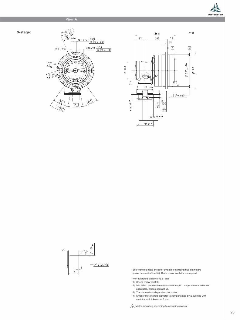
A3-stage:
View A
Non-tolerated dimensions ±1 mm
1) Check motor shaft fit.
2) Min./Max. permissible motor shaft length. Longer motor shafts are
adaptable, please contact us.
3) The dimensions depend on the motor.
4) Smaller motor shaft diameter is compensated by a bushing with
a minimum thickness of 1 mm.
Motor mounting according to operating manual!
See technical data sheet for available clamping hub diameters
(mass moment of inertia). Dimensions available on request.

24
180 240 300 375 420 500 560 600 700 800 875 1000
6000 6000 6000 6000 6000 6000 6000 6000 6000 6000 6000 6000
3350 3350 3350 3800 3350 3350 3350 3350 3350 3350 3800 3350
10000 10000 10000 12500 10000 10000 10000 10000 10000 10000 12500 10000
2700 2900 2900 2900 2900 2900 2900 2900 2900 2900 2900 3200
3800 4000 4000 4000 4000 4000 4000 4000 4000 4000 4000 4200
4500 4500 4500 4500 4500 4500 4500 4500 4500 4500 4500 4500
3,4 2,5 1,6 1,4 1,1 1 1 0,8 0,8 0,7 0,7 0,6
1250 1250 1250 1300 1250 1350 1250 1250 1262 1250 1350 1250
50000
8800
90
> 20000
–
≤ 71
+90
G 24 5,93 4,29 3,33 3,32 2,81 3,19 2,80 2,50 2,74 2,49 2,74 2,46
K 38 12,84 11,18 10,24 10,23 9,72 10,10 9,71 9,41 9,65 9,40 9,65 9,37
4-stage
Ratio a) i
Max. acceleration torque(max. 1000 cycles per hour)
T2B Nm
Nominal output torque(with n1N )
T2N Nm
Emergency stop torque(permitted 1000 times during the service life of the gearhead)
T2Not Nm
Nominal input speed(with T2N and 20°C ambient temperature) b), c) n1N rpm
Max. continuous speed(with 20 % T2N and 20°C ambient temperature)
n1Ncym rpm
Max. input speed n1Max rpm
Mean no load running torque(with n1 = 3000 rpm and 20°C gearhead temperature) d) T012 Nm
Max. torsional backlash jt arcmin Standard ≤ 3,3 / Reduced ≤ 2,3
Torsional rigidity Ct21 Nm/arcmin
Max. axial force e) F2AMax N
Max. tilting moment M2KMax Nm
Efficiency at full load η %
Service life(For calculation, see the Chapter “Information”)
Lh h
Weight incl. standard adapter plate m kg
Operating noise(with n1 = 3000 rpm no load)
LPA dB(A)
Max. permitted housing temperature °C
Ambient temperature °C 0 to +40
Lubrication Lubricated for life
Paint Blue RAL 5002
Direction of rotation Motor and gearhead opposite directions
Protection class IP 65
Moment of inertia(relates to the drive)
Clamping hub diameter [mm]
J1 kgcm2
J1 kgcm2
TPK+ 500 MF 4-stage i=180-1000
a) Other ratios available on requestb) Higher speeds are possible if the nominal torque is reducedc) For higher ambient temperatures, please reduce input speedd) Idling torques decrease during operation e) Refers to center of the output shaft or flange
Please contact us for information on the best configuration for S1 conditions of use (continuous operation).

25
A4-stage:
View A
Non-tolerated dimensions ±1 mm
1) Check motor shaft fit.
2) Min./Max. permissible motor shaft length. Longer motor shafts are
adaptable, please contact us.
3) The dimensions depend on the motor.
4) Smaller motor shaft diameter is compensated by a bushing with
a minimum thickness of 1 mm.
Motor mounting according to operating manual!
See technical data sheet for available clamping hub diameters
(mass moment of inertia). Dimensions available on request.
26
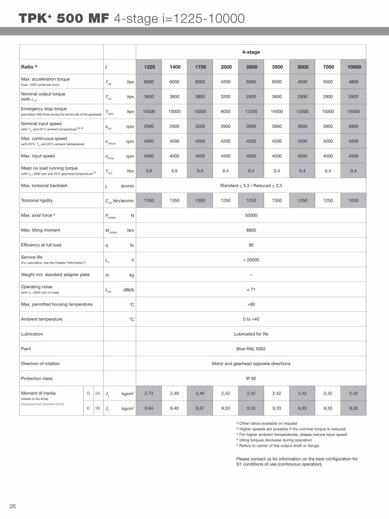
1225 1400 1750 2000 2800 3500 5000 7000 10000
6000 6000 6000 4200 5000 6000 4500 5000 4800
3800 3800 3800 3200 2800 3800 2900 2800 2900
15000 15000 15000 8000 11200 14000 15000 15000 15000
2900 2900 3200 3900 3900 3900 3900 3900 3900
4000 4000 4200 4200 4200 4200 4200 4200 4200
4500 4500 4500 4500 4500 4500 4500 4500 4500
0,6 0,6 0,4 0,4 0,4 0,4 0,4 0,4 0,4
1350 1350 1350 1250 1250 1350 1250 1250 1050
50000
8800
90
> 20000
–
≤ 71
+90
G 24 2,73 2,49 2,46 2,42 2,42 2,42 2,42 2,42 2,42
K 38 9,64 9,40 9,37 9,33 9,33 9,33 9,33 9,33 9,33
4-stage
Ratio a) i
Max. acceleration torque(max. 1000 cycles per hour)
T2B Nm
Nominal output torque(with n1N )
T2N Nm
Emergency stop torque(permitted 1000 times during the service life of the gearhead)
T2Not Nm
Nominal input speed(with T2N and 20°C ambient temperature) b), c) n1N rpm
Max. continuous speed(with 20 % T2N and 20°C ambient temperature)
n1Ncym rpm
Max. input speed n1Max rpm
Mean no load running torque(with n1 = 3000 rpm and 20°C gearhead temperature) d) T012 Nm
Max. torsional backlash jt arcmin Standard ≤ 3,3 / Reduced ≤ 2,3
Torsional rigidity Ct21 Nm/arcmin
Max. axial force e) F2AMax N
Max. tilting moment M2KMax Nm
Efficiency at full load η %
Service life(For calculation, see the Chapter “Information”)
Lh h
Weight incl. standard adapter plate m kg
Operating noise(with n1 = 3000 rpm no load)
LPA dB(A)
Max. permitted housing temperature °C
Ambient temperature °C 0 to +40
Lubrication Lubricated for life
Paint Blue RAL 5002
Direction of rotation Motor and gearhead opposite directions
Protection class IP 65
Moment of inertia(relates to the drive)
Clamping hub diameter [mm]
J1 kgcm2
J1 kgcm2
TPK+ 500 MF 4-stage i=1225-10000
a) Other ratios available on requestb) Higher speeds are possible if the nominal torque is reducedc) For higher ambient temperatures, please reduce input speedd) Idling torques decrease during operation e) Refers to center of the output shaft or flange
Please contact us for information on the best configuration for S1 conditions of use (continuous operation).

27
A4-stage:
View A
Non-tolerated dimensions ±1 mm
1) Check motor shaft fit.
2) Min./Max. permissible motor shaft length. Longer motor shafts are
adaptable, please contact us.
3) The dimensions depend on the motor.
4) Smaller motor shaft diameter is compensated by a bushing with
a minimum thickness of 1 mm.
Motor mounting according to operating manual!
See technical data sheet for available clamping hub diameters
(mass moment of inertia). Dimensions available on request.
28
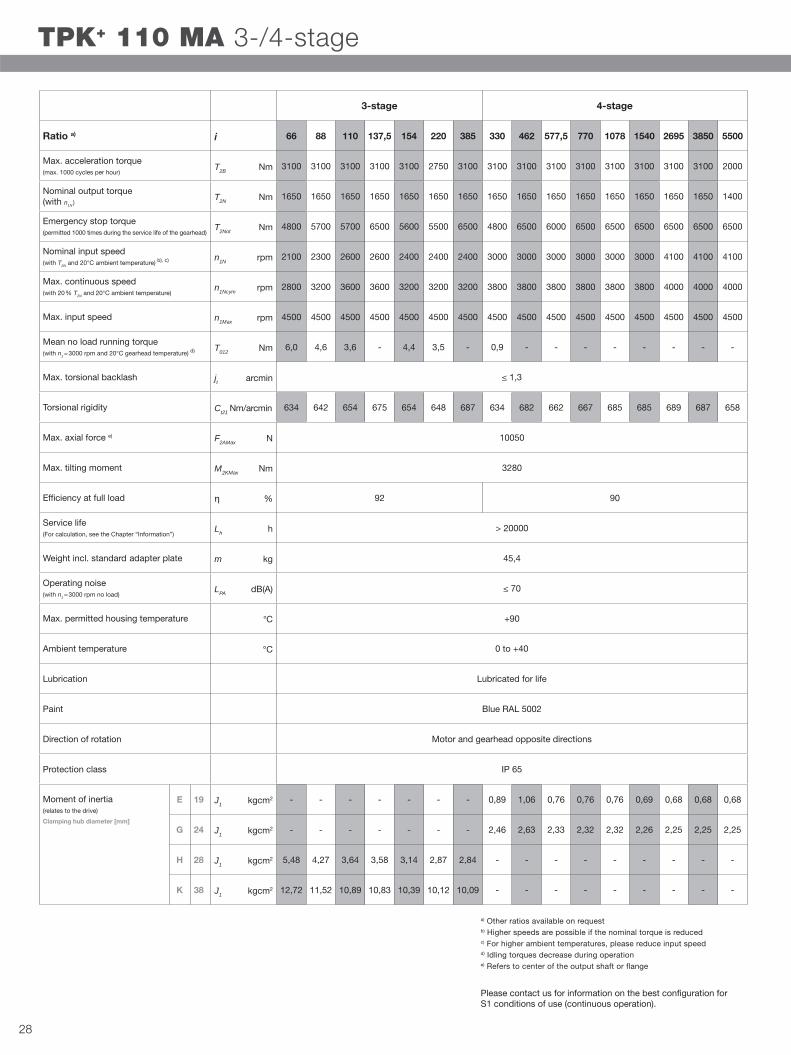
66 88 110 137,5 154 220 385 330 462 577,5 770 1078 1540 2695 3850 5500
3100 3100 3100 3100 3100 2750 3100 3100 3100 3100 3100 3100 3100 3100 3100 2000
1650 1650 1650 1650 1650 1650 1650 1650 1650 1650 1650 1650 1650 1650 1650 1400
4800 5700 5700 6500 5600 5500 6500 4800 6500 6000 6500 6500 6500 6500 6500 6500
2100 2300 2600 2600 2400 2400 2400 3000 3000 3000 3000 3000 3000 4100 4100 4100
2800 3200 3600 3600 3200 3200 3200 3800 3800 3800 3800 3800 3800 4000 4000 4000
4500 4500 4500 4500 4500 4500 4500 4500 4500 4500 4500 4500 4500 4500 4500 4500
6,0 4,6 3,6 - 4,4 3,5 - 0,9 - - - - - - - -
634 642 654 675 654 648 687 634 682 662 667 685 685 689 687 658
10050
3280
92 90
> 20000
45,4
≤ 70
+90
E 19 - - - - - - - 0,89 1,06 0,76 0,76 0,76 0,69 0,68 0,68 0,68
G 24 - - - - - - - 2,46 2,63 2,33 2,32 2,32 2,26 2,25 2,25 2,25
H 28 5,48 4,27 3,64 3,58 3,14 2,87 2,84 - - - - - - - - -
K 38 12,72 11,52 10,89 10,83 10,39 10,12 10,09 - - - - - - - - -
3-stage 4-stage
Ratio a) i
Max. acceleration torque(max. 1000 cycles per hour)
T2B Nm
Nominal output torque(with n1N )
T2N Nm
Emergency stop torque(permitted 1000 times during the service life of the gearhead)
T2Not Nm
Nominal input speed(with T2N and 20°C ambient temperature) b), c) n1N rpm
Max. continuous speed(with 20 % T2N and 20°C ambient temperature)
n1Ncym rpm
Max. input speed n1Max rpm
Mean no load running torque(with n1 = 3000 rpm and 20°C gearhead temperature) d) T012 Nm
Max. torsional backlash jt arcmin ≤ 1,3
Torsional rigidity Ct21 Nm/arcmin
Max. axial force e) F2AMax N
Max. tilting moment M2KMax Nm
Efficiency at full load η %
Service life(For calculation, see the Chapter “Information”)
Lh h
Weight incl. standard adapter plate m kg
Operating noise(with n1 = 3000 rpm no load)
LPA dB(A)
Max. permitted housing temperature °C
Ambient temperature °C 0 to +40
Lubrication Lubricated for life
Paint Blue RAL 5002
Direction of rotation Motor and gearhead opposite directions
Protection class IP 65
Moment of inertia(relates to the drive)
Clamping hub diameter [mm]
J1 kgcm2
J1 kgcm2
J1 kgcm2
J1 kgcm2
TPK+ 110 MA 3-/4-stage
a) Other ratios available on requestb) Higher speeds are possible if the nominal torque is reducedc) For higher ambient temperatures, please reduce input speedd) Idling torques decrease during operation e) Refers to center of the output shaft or flange
Please contact us for information on the best configuration for S1 conditions of use (continuous operation).

29
A3-stage:
4-stage:
View A
Non-tolerated dimensions ±1 mm
1) Check motor shaft fit.
2) Min./Max. permissible motor shaft length. Longer motor shafts are
adaptable, please contact us.
3) The dimensions depend on the motor.
4) Smaller motor shaft diameter is compensated by a bushing with
a minimum thickness of 1 mm.
Motor mounting according to operating manual!
See technical data sheet for available clamping hub diameters
(mass moment of inertia). Dimensions available on request.

30
66 88 110 137,5 154 220 385 330 462 577,5 770 1078 1540 2695 3850 5500
5500 5500 5500 5500 5500 4600 5500 5500 5500 5500 5500 5500 5500 5500 5500 3900
3500 3500 3500 3500 3500 3500 3500 3500 3500 3500 3500 3500 3500 3500 3500 3500
8800 11000 11000 11000 9900 8800 13250 8800 13250 11000 13250 13250 13250 13250 13250 13250
1800 1900 2100 2100 1900 1900 1900 2800 2800 2800 2800 2800 2800 3100 3800 3800
2300 2600 2900 2900 2600 2600 2600 3800 3800 3800 3800 3800 3800 4000 4000 4000
4500 4500 4500 4500 4500 4500 4500 4500 4500 4500 4500 4500 4500 4500 4500 4500
11,0 8,2 6,9 6,5 9,2 6,7 6,4 1,5 2,2 1,0 0,9 0,8 0,6 0,4 0,4 0,4
1099 1108 1114 960 1114 1111 979 1099 976 953 958 978 978 979 979 989
33000
6500
92 90
> 20000
–
≤ 71
+90
G 24 - - - - - - - 3,32 4,24 2,80 2,79 2,79 2,49 2,43 2,42 2,42
K 38 26,04 19,71 16,71 16,58 14,26 12,89 12,83 10,23 11,15 9,71 9,70 9,70 9,40 9,34 9,33 9,33
3-stage 4-stage
Ratio a) i
Max. acceleration torque(max. 1000 cycles per hour)
T2B Nm
Nominal output torque(with n1N )
T2N Nm
Emergency stop torque(permitted 1000 times during the service life of the gearhead)
T2Not Nm
Nominal input speed(with T2N and 20°C ambient temperature) b), c) n1N rpm
Max. continuous speed(with 20 % T2N and 20°C ambient temperature)
n1Ncym rpm
Max. input speed n1Max rpm
Mean no load running torque(with n1 = 3000 rpm and 20°C gearhead temperature) d) T012 Nm
Max. torsional backlash jt arcmin Standard ≤ 3,3 / Reduced ≤ 1,8
Torsional rigidity Ct21 Nm/arcmin
Max. axial force e) F2AMax N
Max. tilting moment M2KMax Nm
Efficiency at full load η %
Service life(For calculation, see the Chapter “Information”)
Lh h
Weight incl. standard adapter plate m kg
Operating noise(with n1 = 3000 rpm no load)
LPA dB(A)
Max. permitted housing temperature °C
Ambient temperature °C 0 to +40
Lubrication Lubricated for life
Paint Blue RAL 5002
Direction of rotation Motor and gearhead opposite directions
Protection class IP 65
Moment of inertia(relates to the drive)
Clamping hub diameter [mm]
J1 kgcm2
J1 kgcm2
TPK+ 300 MA 3-/4-stage
a) Other ratios available on requestb) Higher speeds are possible if the nominal torque is reducedc) For higher ambient temperatures, please reduce input speedd) Idling torques decrease during operation e) Refers to center of the output shaft or flange
Please contact us for information on the best configuration for S1 conditions of use (continuous operation).
31
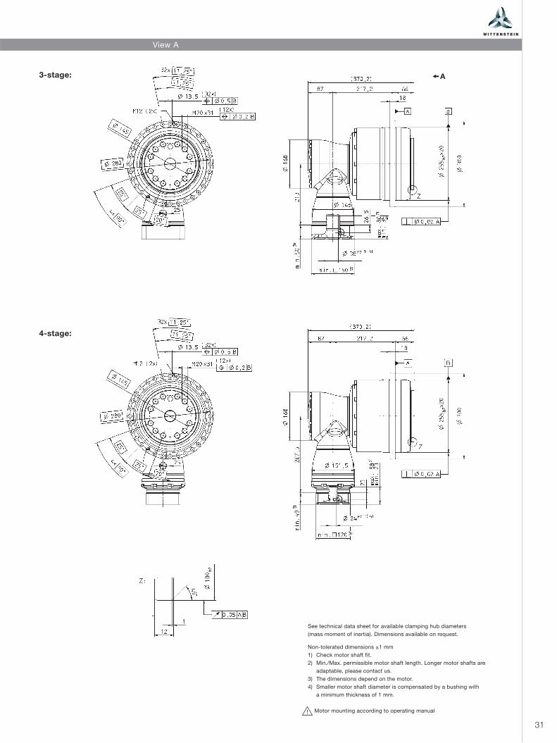
A3-stage:
4-stage:
View A
Non-tolerated dimensions ±1 mm
1) Check motor shaft fit.
2) Min./Max. permissible motor shaft length. Longer motor shafts are
adaptable, please contact us.
3) The dimensions depend on the motor.
4) Smaller motor shaft diameter is compensated by a bushing with
a minimum thickness of 1 mm.
Motor mounting according to operating manual!
See technical data sheet for available clamping hub diameters
(mass moment of inertia). Dimensions available on request.

32
66 88 110 137,5 154 220 385 330 462 577,5 770 1078 1540 2695 3850 5500
10000 10000 10000 10000 10000 10000 10000 10000 10000 10000 10000 10000 10000 10000 10000 7200
4200 5400 5400 5400 5400 5400 5400 5400 5400 5400 5400 5400 5400 5400 5400 5400
19800 23000 23000 25000 21300 19800 25000 19800 25000 25000 25000 25000 25000 25000 25000 25000
1500 1700 1900 1900 1700 1700 1700 2600 2600 2600 2600 2600 2600 3100 3300 3300
1800 2200 2600 2600 2300 2300 3100 3300 3300 3300 3300 3300 3300 3600 3600 3600
4000 4000 4000 4000 4000 4000 4000 4000 4000 4000 4000 4000 4000 4000 4000 4000
18,8 15,3 12,6 12,8 16,9 13,8 13,7 2,7 4,0 2,0 1,8 1,7 1,2 1,1 1,0 1,0
1879 1890 1901 1747 1899 1898 1772 1879 1766 1735 1742 1770 1770 1772 1772 1786
50000
9500
92 90
> 20000
–
≤ 71
+90
K 38 - - - - - - - 12,43 15,36 10,93 10,92 10,91 10,13 9,95 9,91 9,91
M 48 75,54 52,83 42,94 42,67 34,37 29,87 29,73 27,14 30,07 25,64 25,63 25,62 24,84 24,66 24,62 24,62
TPK+ 500 MA 3-/4-stage
3-stage 4-stage
Ratio a) i
Max. acceleration torque(max. 1000 cycles per hour)
T2B Nm
Nominal output torque(with n1N )
T2N Nm
Emergency stop torque(permitted 1000 times during the service life of the gearhead)
T2Not Nm
Nominal input speed(with T2N and 20°C ambient temperature) b), c) n1N rpm
Max. continuous speed(with 20 % T2N and 20°C ambient temperature)
n1Ncym rpm
Max. input speed n1Max rpm
Mean no load running torque(with n1 = 3000 rpm and 20°C gearhead temperature) d) T012 Nm
Max. torsional backlash jt arcmin Standard ≤ 3,3 / Reduced ≤ 1,8
Torsional rigidity Ct21 Nm/arcmin
Max. axial force e) F2AMax N
Max. tilting moment M2KMax Nm
Efficiency at full load η %
Service life(For calculation, see the Chapter “Information”)
Lh h
Weight incl. standard adapter plate m kg
Operating noise(with n1 = 3000 rpm no load)
LPA dB(A)
Max. permitted housing temperature °C
Ambient temperature °C 0 to +40
Lubrication Lubricated for life
Paint Blue RAL 5002
Direction of rotation Motor and gearhead opposite directions
Protection class IP 65
Moment of inertia(relates to the drive)
Clamping hub diameter [mm]
J1 kgcm2
J1 kgcm2
a) Other ratios available on requestb) Higher speeds are possible if the nominal torque is reducedc) For higher ambient temperatures, please reduce input speedd) Idling torques decrease during operation e) Refers to center of the output shaft or flange
Please contact us for information on the best configuration for S1 conditions of use (continuous operation).

33
A3-stage:
4-stage:
View A
Non-tolerated dimensions ±1 mm
1) Check motor shaft fit.
2) Min./Max. permissible motor shaft length. Longer motor shafts are
adaptable, please contact us.
3) The dimensions depend on the motor.
4) Smaller motor shaft diameter is compensated by a bushing with
a minimum thickness of 1 mm.
Motor mounting according to operating manual!
See technical data sheet for available clamping hub diameters
(mass moment of inertia). Dimensions available on request.

34
TPK+/SPK+
S P K + 2 1 0 S – M F 2 – 16 – 0 M 1
Order Information
Gearhead type
TPK+ 300 – TPK+ 500
SPK+ 210 – SPK+ 240
Type code
S = Standard
F = Food lubrication
B = Modular output
combination
Number of stages
2 = 2-stage
3 = 3-stage
4 = 4-stage
Gearhead model
A = High Torque (only TPK+)
F = Standard
Gearhead variations
M = Motor attachment
gearhead
Order codes
cymex® 3.1 – Software for drive technology
cymex® enables the simple dimensioning and design of complete drive trains (application + motor + gearhead). Standard predefined applications make precise calculations so much easier. Consideration for all major influencing factors and specific customer parameters guarantee the perfect design for your drive system.
Gearhead type Type code
Gearhead variations
Gearhead model
Number of stages
Ratios
Output shaft shape
Clamping hub bore
hole diameter
Backlash
Established features
• Standard predefined applications• cymex® profiler for creating simple or complex
motion and load profiles• Functions for importing motion profiles from
SAM, Excel, ASCII• Application data and technical data documented
in Microsoft Word• Offline CAD generator: 3D gearhead files includ-
ing all attached components compatible with the selected motor
• Database containing all current WITTENSTEIN alpha products• Largest global database with more than 7000
motors offered by all current manufacturers

35
Output shape
0 = smooth shaft/flange
1 = shaft with key
2 = involute to DIN 5480
3 = system output
4 = other(see technical data sheets)
Backlash
1 = Standard
0 = Reduced
(see technical data sheets)
Ratios
See technical data sheets.
Clamping hub bore hole
diameter
(see technical data sheets and clamping hub diameter table)

SP
K+
TP
K+
kata
log
_u
s_2
00
9_I Te
ch
nic
al ch
an
ges r
eserv
ed
alpha
WITTENSTEIN alpha · 1249 Humbracht Circle · Bartlett, IL 60103, USA · Tel. +1 630 540-5300 · [email protected]