Spiral Photon Sieves Apodized by a Bessel-Like Windowjpier.org/PIERC/pierc72/05.16111502.pdf ·...
9
Progress In Electromagnetics Research C, Vol. 72, 55–63, 2017 Spiral Photon Sieves Apodized by a Bessel-Like Window Jian Yu 1, 2 , Shali Xiao 1 , Tao Yi 2 , Jin Li 2 , Zhiwen Yang 2 , and Shenye Liu 2, * Abstract—In order to improve the focusing and imaging effects of conventional spiral zone plates (SZPs), we design a new type of spiral photon sieve (SPSs) apodized by a robust Bessel-like window. The design principle and numerical simulation results show that the Bessel-like window has a better modulation effect on the main lobe compression and side suppression of the point spread function (PSF) than other traditional window. Taking advantage of the robustness of Bessel-like windows, the proposed SPS can achieve a higher spatial resolution and lower side lobe noise than the conventional SPS and SZP. The practical effects have also been demonstrated by image experiments on the micropore. Our work may find some potential applications in laser alignment, optical trapping, optical communication and edge enhancement imaging fields. 1. INTRODUCTION A spiral zone plate (SZP) is an important type of diffractive optical element. It is often used in edge enhancement imaging, owing to its isotropic radial Hilbert transform function [1–3]. Due to the dark core structure of the focal spot, it also has a number of potential applications for astronomical observations and laser alignment [4–6]. In addition, the SZP has the potential for use in particle manipulation and optical communication, since it imparts an orbital angular momentum to the incident light [7, 8]. Unfortunately, as with a conventional Fresnel zone plate (FZP) [9], the spatial resolution of the SZP is limited by the width of its outermost zone. Moreover, the side lobe noise of the SZP increases significantly with increased topological charge number, similar to a spiral phase plate (SPP) [10, 11]. The inadequate spatial resolution and the serious side lobe noise hinder the use of an SZP in many cases, such as for edge enhancement imaging and multiple optical traps. Due to the complexity of the design, there has been relatively little research into how to improve the characteristics of the SZP. To the best of our knowledge, only Bokor and Iketaki extended the conventional SZP to a Laguerre-Gaussian zone plate [2] and Xie et al. extended the conventional SZP to an SPS apodized by a digital prolate spheroidal window [12]. Compared to a conventional SZP, to some extent, the Laguerre-Gaussian zone plate reduces the side lobe noise, but its spatial resolution is still limited by the width of its outermost zone. Both the spatial resolution and the side lobe noise of the SPS are better than that of the conventional SZP due to the advantages of the design and modulation of traditional photon sieves (PS) [13]; however, with the digital prolate spheroidal window, the main lobe compression and side lobe suppression effects of the point spread function (PSF) are still not optimal because the suppression of the side lobes takes place with non-ignorable main lobe expansion. In fact, due to its small size, light weight and flexible design, the photon sieve has seen great development since it was invented [13–16]. So far, a large number of diffractive optical elements based on this type of multi-micropore structure have emerged, such as flat helical nanosieves [17] and ultrahigh- capacity non-periodic photon sieves [18]. The amplitude, phase and polarization of the diffracted light Received 15 November 2016, Accepted 14 February 2017, Scheduled 1 March 2017 * Corresponding author: Shenye Liu ([email protected]). 1 College of Optoelectronic Engineering, Chongqing University, Chongqing 400044, China. 2 Research Center of Laser Fusion, China Academy of Engineering Physics, P. O. Box 919-986, Mianyang 621900, China.
Transcript of Spiral Photon Sieves Apodized by a Bessel-Like Windowjpier.org/PIERC/pierc72/05.16111502.pdf ·...

Progress In Electromagnetics Research C, Vol. 72, 55–63, 2017
Spiral Photon Sieves Apodized by a Bessel-Like Window
Jian Yu1, 2, Shali Xiao1, Tao Yi2, Jin Li2, Zhiwen Yang2, and Shenye Liu2, *
Abstract—In order to improve the focusing and imaging effects of conventional spiral zone plates(SZPs), we design a new type of spiral photon sieve (SPSs) apodized by a robust Bessel-like window.The design principle and numerical simulation results show that the Bessel-like window has a bettermodulation effect on the main lobe compression and side suppression of the point spread function (PSF)than other traditional window. Taking advantage of the robustness of Bessel-like windows, the proposedSPS can achieve a higher spatial resolution and lower side lobe noise than the conventional SPS andSZP. The practical effects have also been demonstrated by image experiments on the micropore. Ourwork may find some potential applications in laser alignment, optical trapping, optical communicationand edge enhancement imaging fields.
1. INTRODUCTION
A spiral zone plate (SZP) is an important type of diffractive optical element. It is often used in edgeenhancement imaging, owing to its isotropic radial Hilbert transform function [1–3]. Due to the dark corestructure of the focal spot, it also has a number of potential applications for astronomical observationsand laser alignment [4–6]. In addition, the SZP has the potential for use in particle manipulationand optical communication, since it imparts an orbital angular momentum to the incident light [7, 8].Unfortunately, as with a conventional Fresnel zone plate (FZP) [9], the spatial resolution of the SZPis limited by the width of its outermost zone. Moreover, the side lobe noise of the SZP increasessignificantly with increased topological charge number, similar to a spiral phase plate (SPP) [10, 11].The inadequate spatial resolution and the serious side lobe noise hinder the use of an SZP in manycases, such as for edge enhancement imaging and multiple optical traps.
Due to the complexity of the design, there has been relatively little research into how to improvethe characteristics of the SZP. To the best of our knowledge, only Bokor and Iketaki extended theconventional SZP to a Laguerre-Gaussian zone plate [2] and Xie et al. extended the conventional SZPto an SPS apodized by a digital prolate spheroidal window [12]. Compared to a conventional SZP, tosome extent, the Laguerre-Gaussian zone plate reduces the side lobe noise, but its spatial resolution isstill limited by the width of its outermost zone. Both the spatial resolution and the side lobe noise of theSPS are better than that of the conventional SZP due to the advantages of the design and modulation oftraditional photon sieves (PS) [13]; however, with the digital prolate spheroidal window, the main lobecompression and side lobe suppression effects of the point spread function (PSF) are still not optimalbecause the suppression of the side lobes takes place with non-ignorable main lobe expansion.
In fact, due to its small size, light weight and flexible design, the photon sieve has seen greatdevelopment since it was invented [13–16]. So far, a large number of diffractive optical elements basedon this type of multi-micropore structure have emerged, such as flat helical nanosieves [17] and ultrahigh-capacity non-periodic photon sieves [18]. The amplitude, phase and polarization of the diffracted light
Received 15 November 2016, Accepted 14 February 2017, Scheduled 1 March 2017* Corresponding author: Shenye Liu ([email protected]).1 College of Optoelectronic Engineering, Chongqing University, Chongqing 400044, China. 2 Research Center of Laser Fusion, ChinaAcademy of Engineering Physics, P. O. Box 919-986, Mianyang 621900, China.

56 Yu et al.
field behind these multi-micropore structures can be effectively controlled by adjusting the geometrypositions and sizes of individual holes with an excellent transmittance modulation window function orother algorithm. In this paper, we extend a conventional SZP to an SPS apodized by a Bessel-likemodulation window in visible light to optimize the spatial resolution and suppress the side lobe noise.Then the reasons that the proposed SPSs have optimal focusing and imaging effects will be discussed indetail. The improvement in spatial resolution and the side lobe noise will also be shown in the followingsections.
2. DESIGN AND ANALYSIS
In fact, the Bessel-like window was proposed to completely suppress the side lobe noise of the SPPin [19]. According to Chen et al., the side lobes arise from diffraction by the margins as well as thecenter section of the SPP. Although the manufacture of the SPP with the Bessel-like modulation is verydifficult, the modulation effect of a Bessel-like window is ideal since it takes advantage of the specialintegral formula of the Bessel function and the optimal modulation parameters. If we use the sameBessel-like window to modulate the transmission of the SZP/SPS, the Fresnel diffraction pattern at thefocal plane will be given by the following integral formula in polar coordinates
Ep (ρ, ϕ) =1
iλf
R∫0
2π∫0
[fp (r)SZPp (r, θ)] exp(
iπr2
λf
)× exp
[2πρr
λfcos (θ − ϕ)
]rdrdθ
= (−i)p+1 k
fexp (ipϕ)
R∫0
Jp+1 (αr)Jp
(k
fρr
)dr
(1)
where p is the topological charge number, λ the wavelength, f the focus length, k the wave number, (r,θ) the polar coordinates in SZP/SPS plane, (ρ, ϕ) the polar coordinates in the focal plane, SZPp(r, θ)the phase function of the SZP [1], and fp(r) the Bessel-like window function. Equation (1) ignores thequadratic phase factor. fp(r) is used in the following expression to better suppress the side lobes of theoptical vortex with a small topological charge [19, 20].
fp (r) =Jp+1 (αr)
r(2)
where α = γp+1,1/R, γp+1,1 is the first root of the (p+1) order Bessel function of the first kind, and Ris the maximum radius of the SZP/SPS. Equation (1), above, is very similar to Equation (3) in [19],which means that the same modulation approach can be applied to improve the SZP/SPS and that theside lobes of the SZP/SPS also arise from diffraction at the center and margins. In order to overcomethe spatial resolution limitation by the width of the outermost zone and suppress the side lobe noise,to take advantage of the design flexibility, in this paper we propose an SPS apodized by the Bessel-likewindow.
The following will introduce the specific design method of the SPS apodized by the Bessel-likewindow. The boundary of the SZP is defined by the following curve equations [5]
pθ = (n + 1/2)π +kr2
2f(3)
where n = 0, ±1, ±2, ±3 . . .. In keeping with the design method of a traditional PS, we replace theclear zones of the SZP by a large number of nonoverlapping pinholes to create an SPS. We also definea zone to be the rotation area when the clear helical structure is rotated 2π radian from the inside tothe outside. The design parameters of the SPS are as follows: λ = 532 nm, f = 100 mm, d/w = 1.5,δ = 4.7 µm, where d is the pinhole diameter, w the width of the local zone of the underlying SZP,and δ the minimum feature size. Fig. 1(a) clearly shows the design process of a single ring in theSPS with a topological charge number p = 1. The binarized double-spiral plane structure represents aconventional SZP with p = 1, where the white zones are transparent, and the black zones are opaque.The red circles represent the transparent pinholes used to replace the clear zone in the conventionalSZP. The transmission of the SPS can easily meet the criteria of a Bessel-like window function by

Progress In Electromagnetics Research C, Vol. 72, 2017 57
(b)
(a)
(c)
Figure 1. Design process of the SPS with topological charge number p = 1.
flexibly adjusting the positions of the pinholes for each zone. In addition, due to a simple binarizedplane structure, the fabrication is not difficult. Fig. 1(b) shows the corresponding Bessel-like functioncurve (fp(r) = J2(αr)/r) and the specific Bessel-like modulation window. When r = R, the modulationrange of the Bessel-like window along the radial direction will be cut off. We also show the transmissionareas of different ring numbers N in Fig. 1(c).
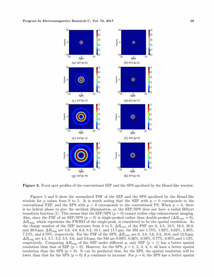
An SPS with different topological charges can realize edge enhancement imaging of an object withdifferent spiral phase contrasts, so we have designed the SPS with an arbitrary topological charge.However, given the practicalities of the existing processing technology, we only test the SPSs with asmall p, here. Schematic views of the SPS with topological charge numbers p = 1, 2, 3, 4 are shown inFig. 2.
According to the Fresnel diffraction integral formula and the superposition principle for a lightfield, any point field distribution on the focal plane of an SPS is the summation of the contributionsof all the pinholes, when using a plane wave as the incident illumination. The focal spot images of theSZP and SPS shown in Fig. 3 demonstrate that destructive interference occurs in the center of all focusspots and that the spot size increases as p increases. If the topological charge and minimum feature sizestay constant, the numerical aperture (NA) of the SPS is larger than that of the SZP. Hence, the SPShas a substantially better spatial resolution, according to the Rayleigh resolution criterion. With theBessel-like window’s modification, due to the low side lobe noise, the vortex spots of SPS are simplerand cleaner.
Figure 4 shows the normalized PSF of the SZP (p = 1) and SPS (p = 1) apodized by several differentwindows. Some important parameters for each case are given in the figure, where ΔRcore, ΔRring andSM represents the FWHM of the dark core diameter, the FWHM of the doughnut-shaped ring width,and the ratio of the secondary to the principal maximum, respectively. When the SZP/SPS is considered

58 Yu et al.
(b)(a)
(d)(c)
Figure 2. Schematic views of the SPS with different topological charge.
as a focusing and imaging element, ΔRcore determines the magnification, since a larger ΔRcore meansthat any two point sources on the object appear farther apart. By combining the topological chargenumber with the object-image distance, we can change the magnification easily. Here, unlike for aconventional FZP, the PSF of the SZP/SPS shows a double-peaked structure, so ΔRring is consideredto be the spatial resolution of the SZP/SPS [21]. Reducing ΔRring will improve the spatial resolutionof the apparatus. In addition, since the influences arising from the secondary maximum have seriousrepercussions for the signal-to-noise ratio of the focusing and imaging image, the parameter SM shouldalso be as low as possible.
According to the curves and data in Fig. 4, the Bessel-like window has better effects in main lobecompression and side lobe suppression than the conventional SZP and SPS apodized by the conventionalBlackman or Hanning windows. ΔRring of the SPS apodized by a Bessel-like window is 3.1 µm. ΔRring
of the three other cases are 4.0, 3.3, 3.4 µm, respectively. Most notably, the SM of the SPS apodized bya Bessel-like window can be as low as 0.36%. However, the SM of the SZP and SPS apodized by theBlackman and Hanning windows are as high as 1.92%, 3.87%, 2.13%. There are two reasons that theSPS apodized by a Bessel-like window has advantages over the other types: (1) a Bessel-like windowwith optimal modulation parameters can effectively suppress the side lobes arising from the diffractionof the center and marginal sections of the SPS, since it can appropriately modulate transmission throughthose areas; (2) the suppression of the side lobes takes place with negligible main lobe expansion [19, 20].The Blackman and Hanning windows, on the other hand, only appropriately modulate transmission atthe marginal part, similar to a Laguerre-Gaussian window or a digital prolate spheroidal window.Thus, they are not able to effectively suppress the side lobes arising from the diffraction of the center.Additionally, main lobe expansion is non-negligible when using Blackman or Hanning windows. Alsonote that only the Bessel-like window has a lower SM than the SZP. The transmission curve of theSZP shows that the center and marginal transmission of the SZP is inherently low [22]. Thus, theproportion of the transmission through center is higher using the Blackman or Hanning window thanfor the conventional SZP. As a result, an SPS apodized by a Blackman or Hanning window has a higherSM than the conventional SZP. However, the inherent transmission of the SZP is not optimal for sidelobe suppression compared with the modulation effects of the robust Bessel-like window.
Progress In Electromagnetics Research C, Vol. 72, 2017 59
(b)(a)
(d)(c)
(f)(e)
(h)(g)
Figure 3. Focal spot profiles of the conventional SZP and the SPS apodized by the Bessel-like window.
Figures 5 and 6 show the normalized PSF of the SZP and the SPS apodized by the Bessel-likewindow for p values from 0 to 5. It is worth noting that the SZP with p = 0 corresponds to theconventional FZP, and the SPS with p = 0 corresponds to the conventional PS. When p = 0, thereis no helical phase to give the incident illumination, so the SZP/SPS does not have a radial Hilberttransform function [1]. This means that the SZP/SPS (p = 0) cannot realize edge enhancement imaging.Also, since the PSF of an SZP/SPS (p = 0) is single-peaked rather than double-peaked (ΔRcore = 0),ΔRring, which represents the FWHM of the single-peak, is considered to be the spatial resolution. Asthe charge number of the SZP increases from 0 to 5, ΔRcore of the PSF are 0, 3.5, 10.5, 19.3, 28.9,and 39.8 µm; ΔRring are 4.9, 4.0, 6.3, 8.2, 10.1, and 11.7 µm; the SM are 1.75%, 1.92%, 3.62%, 5.38%,7.15%, and 8.78%, respectively. For the PSF of the SPS, ΔRcore are 0, 2.8, 5.6, 8.2, 10.6, and 12.9 µm;ΔRring are 4.1, 3.1, 3.3, 3.5, 3.6, and 3.6 µm; the SM are 0.09%, 0.36%, 0.59%, 0.77%, 0.95%,and 1.13%,respectively. Comparing ΔRring of the SZP under different p, only SZP (p = 1) has a better spatialresolution than that of SZP (p = 0). However, for the SPS, p = 1, 2, 3, 4, 5, all have a better spatialresolution than the SPS (p = 0). It can be predicted that, for the SPS, the spatial resolution will belower than that for the SPS (p = 0) if p continues to increase. For p = 0, the SPS has a better spatial

60 Yu et al.
Figure 4. PSF of the conventional SZP and the SPS apodized by different windows.
Figure 5. PSF of the conventional SZP.
Figure 6. PSF of the SPS apodized by the Bessel-like window.

Progress In Electromagnetics Research C, Vol. 72, 2017 61
resolution than the SZP, and, more importantly, the intensity of the side lobes of the SPS is extremelylow. If p �= 0, because the selected clear zones are not radially symmetric, the difference between thetransmission values for the actual modulation and the real Bessel-like window will increase slowly as pincreases. This also leads to a very slow increase in the SM values. Depending on the robustness ofBessel-like window, however, all SM of the SPS are still very low. To sum up, for p values from 0 to 5,the reduced dark core diameters are 0, 0.7, 4.9, 11.1, 18.3, and 26.9 µm; the improved spatial resolutionsare 0.8, 0.9, 3.0, 4.7, 6.5, and 8.1 µm; the improved SM are 1.66%, 1.56%, 3.03%, 4.61%, 6.20%, and7.65%, respectively.
3. EXPERIMENTAL SIMULATION
A conventional SZP can achieve isotropic edge enhancement imaging for the amplitude object or phaseobject in a single step by combining the radial Hilbert transform filtering function with the FZP focusingfunction. The design of the SPS apodized by the Bessel-like window is based on the conventional SZP,so it also has the same isotropic edge enhancement imaging effect. In order to compare the imagingeffects of the SZP and SPS, we take the micropore with a diameter 30 µm as an example and carry outa numerical simulation of its imaging experiments. In the simulation, we choose the first-order SZP andfirst-order SPS in turn as imaging devices. The magnifications of the images are set to 1.
Figure 7(a) shows the micropore picture, where the white area is clear, and the black area is opaque.Figs. 7(b) and (c) show the isotropic edge enhancement imaging results of the micropore by using theSZP and SPS, respectively. However, the imaging effects have an obvious difference in Fig. 7(b) andFig. 7(c). In Fig. 7(b), there is a large amount of noise around the ring structure, which is usuallycalled the “relief effect”. This effect is mainly caused by the side lobes of the PSF of SZP, and itspresence often leads to wrong interpretations, especially in the field of medical imaging. As we can seein Fig. 7(c), the ring image is very clear, and there is almost no interference noise. In fact, this effectresults from the efficient side lobe suppression of the Bessel-like window. In addition, comparing thetwo imaging results carefully, we also see that the ring widths of the ring images are quite different.Figs. 7(e) and (f) show the normalized intensity distribution curves from the center of the ring image to
(c)
(a)
(b)
(e)
(d)
Figure 7. Numerical simulation results of the micropore imaging.

62 Yu et al.
the edge of the ring image, respectively. According to the normalized intensity distribution data alongthe radial direction, we see that the FWHM of the ring in Fig. 7(e) is 6.9 µm, and the FWHM of thering in Fig. 7(f) is 4.5 µm.
4. CONCLUSION
In conclusion, taking advantage of the robustness of Bessel-like windows, the SPS has a higher spatialresolution and lower side lobe noise than a conventional SPS and SZP. In edge enhancement imaging,the image quality will be improved greatly. Of course, due to these improvements, the SPS is also veryuseful for the astronomical observations, laser alignment and particle trap fields. Finally, it is also worthnoting here that the diffraction efficiency of the SPS is lower than that of the SZP since pinholes havereplaced the original clear zones. Fortunately, this disadvantage can be remedied by using high intensitysources, such as third-generation synchrotron light sources, since this allows the SPS to be used closeto its diffraction efficiency limit.
ACKNOWLEDGMENT
The authors acknowledge support from the Beijing Institute of Microelectronics, Chinese Academyof Sciences. Our work is supported by the National Natural Science Foundation of China (GrantNos. 11405158).
REFERENCES
1. Sakdinawat, A. and Y. W. Liu, “Soft-x-ray microscopy using spiral zone plates,” Opt. Lett., Vol. 32,2635–2637, 2007.
2. Bokor, N. and Y. Iketaki, “Laguerre-Gaussian radial Hilbert transform for edge-enhancementFourier transform x-ray microscopy,” Opt. Express, Vol. 17, 5533–5539, 2009.
3. Sharma, M. K., R. K. Singh, J. Joseph, and P. Senthilkumaran, “Fourier spectrum analysis ofspiral zone plates,” Opt. Commun., Vol.304, 43–48, 2013.
4. Mawet, D. E. Serabyn, J. K. Wallace, and L. Pueyo, “Improved high-contrast imaging with on-axistelescopes using a multistage vortex coronagraph,” Opt. Lett., Vol. 36, 1506–1508, 2011.
5. Heckenberg, N., R. McDuff, C. Smith, and A. White, “Generation of optical phase singularities bycomputer-generated holograms,” Opt. Lett., Vol. 17, 221–223, 1992.
6. Luo, D., C. Kuang, X. Hao, and X. Liu, “High-precision laser alignment technique based on spiralphase plate,” Opt. Laser. Eng., Vol. 50, 944–949, 2012.
7. Ng, J., Z. Lin, and C. T. Chan, “Theory of optical trapping by an optical vortex beam,” Phys.Rev. Lett., Vol. 104, 103601, 2010.
8. Gibson, G., J. Courtial, M. Padgett, M. Vasnetsov, V. Pas’ko, S. M. Barnett, and S. Franke-Arnold, “Free-space information transfer using light beams carrying orbital angular momentum,”Opt. Express, Vol. 12, 5448–5456, 2004.
9. Chao, W., J. Kim, S. Rekawa, P. Fischer, and E. H. Anderson, “Demonstration of 12 nm resolutionFresnel zone plate lens based soft x-ray microscopy,” Opt. Express, Vol. 17, 17669–17677, 2009.
10. Lin, J., X. C. Yuan, S. H. Tao, and R. E. Burge, “Variable radius focused optical vortex withsuppressed sidelobes,” Opt. Lett., Vol. 31, 1600–1602, 2006.
11. Guo, C. S., Y. J. Han, J. B. Xu, and J. P. Ding, “Radial Hilbert transform with Laguerre-Gaussianspatial filters,” Opt. Lett., Vol. 31, 1394–1396, 2006.
12. Xie, C. Q., X. L. Zhu, L. Shi, and M. Liu, “Spiral photon sieves apodized by digital prolatespheroidal window for the generation of hard-x-ray vortex,” Opt. Lett., Vol. 35, 1765–1767, 2010.
13. Kipp, L., M. Skibowski, R. Johnson, R. Berndt, R. Adelung, S. Harm, and R. Seemann, “Sharperimages by focusing soft X-rays with photon sieves,” Nature, Vol. 414, 184–188, 2001.
14. Cheng, G., C. Hu, P. Xu, and T. Xing, “Zernike apodized photon sieves for high-resolution phase-contrast x-ray microscopy,” Opt. Lett., Vol. 35, 3610–3612, 2010.

Progress In Electromagnetics Research C, Vol. 72, 2017 63
15. Andersen, G., “Membrane photon sieve telescopes,” Appl. Opt., Vol. 49, 6391–6394, 2010.16. Zhao, X., J. Hu, F. Xu, A. Zhu, and C. Wang, “Wide field-of-view imaging with wavefront coded
diffractive photon sieves,” IEEE Photonics J., Vol. 8, 1–8, 2016.17. Mei, S., M. Q. Mehmood, S. Hussain, K. Huang, X. Ling, S. Y. Siew, H. Liu, J. Teng, A. Danner,
and Qiu, C., “Flat helical nanosieves,” Adv. Funct. Mater., Vol. 26, 1–8, 2016.18. Huang, K., H. Liu, F. J. Garcia-Vidal, M. Hong, B. Luk’yanchuk, J. Teng, and C. W. Qiu,
“Ultrahigh-capacity non-periodic photon sieves operating in visible light,” Nat. commun., Vol. 6,1–7, 2015.
19. Chen, J., X.-C. Yuan, X. Zhao, Z. Fang, and S. Zhu, “Generalized approach to modifying opticalvortices with suppressed sidelobes using Bessel-like functions,” Opt. Lett., Vol. 34, 3289–3291, 2009.
20. Chen, J., X. Zhao, Z. Fang, S. Zhu, and X.-C. Yuan, “Explicit relations and optimal parametersfor sidelobe suppression in optical vortices with a modified Bessel function,” J. Opt. Soc. Am. A,Vol. 27, 935–940, 2010.
21. Palacios, D., “An optical vortex coherence filter,” Ph.D. Thesis, 2004.22. Yi, T., L.-F. Cao, G.-H. Yang, S.-S. Liu, X.-L. Zhu, C.-Q. Xie, and J.-J. Dong, “Edge enhancement
imaging using spiral zone plate,” High Power Laser and Particle Beams, Vol. 22, 2075–2078, 2010.


![Fourier-Bessel Analysis of Cyllindrically Symmetric ... · other members of professor Gauthier’s group using Bessel-Legendre-Fourier technique [8]. By using a Fourier-Bessel set](https://static.fdocuments.in/doc/165x107/5f5e2e5a108c766ffb3ab4fc/fourier-bessel-analysis-of-cyllindrically-symmetric-other-members-of-professor.jpg)