SPIN ON POWER UP - EDGEedge.rit.edu/content/P15201/public/MSD II/CE/Documentation... · Motor will...
46
C LEAR P ATH U SER M ANUAL R EV . 1.89 39 TEKNIC, INC. FAX (585)784-7460 VOICE (585)784-7454 SPIN ON POWER UP. MODE SUMMARY This is ClearPath’s simplest mode of operation. Just turn on power and ClearPath smoothly ramps to your preset velocity. Use this mode for applications that require reliable constant velocity and a bare minimum of wiring. HOW IT WORKS Apply main DC power and ClearPath immediately ramps up to your target velocity (target velocity and acceleration are defined by the user during setup). ClearPath spins at the target velocity until DC power is removed. All inputs are ignored, but the output (High-Level Feedback) is functional. Note: When power is removed in this mode, ClearPath may stop abruptly or coast a short distance depending on the application and motor winding configuration. Carefully test your loaded ClearPath application for stopping behavior before deploying. Signal Function Input Type Input A Motor velocity vs. time Input B Disabled Disabled Disabled NA NA Main DC Power NA NA NA 0 1 0 1 0 1 t v Example Timing Caution! Motor shaft may spin as soon as main DC power is applied. Notes: All inputs are ignored in this mode. High-Level Feedback is available. Motor will free-wheel when DC power is removed, unless external braking force is applied. Motor may stop abruptly depending on load conditions. Enable NA OFF ON Spin On Power Up Velocity Control Motor free-wheeling Spin-On-Power-Up Mode: Inputs and Timing Diagram
Transcript of SPIN ON POWER UP - EDGEedge.rit.edu/content/P15201/public/MSD II/CE/Documentation... · Motor will...

C L E A R P A T H U S E R M A N U A L R E V . 1 . 8 9 39
TEKNIC, INC. FAX (585)784-7460 VOICE (585)784-7454
SPIN ON POWER UP.
MODE SUMMARY This is ClearPath’s simplest mode of operation. Just turn on power and ClearPath smoothly ramps to your preset velocity. Use this mode for applications that require reliable constant velocity and a bare minimum of wiring.
HOW IT WORKS Apply main DC power and ClearPath immediately ramps up to your target velocity (target velocity and acceleration are defined by the user during setup). ClearPath spins at the target velocity until DC power is removed. All inputs are ignored, but the output (High-Level Feedback) is functional.
Note: When power is removed in this mode, ClearPath may stop abruptly or coast a short distance depending on the application and motor winding configuration. Carefully test your loaded ClearPath application for stopping behavior before deploying.
Signal Function Input Type
Input A
Motor velocity vs. time
Input B
Disabled
Disabled
Disabled NA
NA
Main DC Power
NA
NA
NA 0
1
0
1
0
1
t
v
Example Timing
Caution! Motor shaft may spin as soon as main DC power is applied. Notes: All inputs are ignored in this mode. High-Level Feedback is available.Motor will free-wheel when DC power is removed, unless external braking force is applied. Motor may stop abruptly depending on load conditions.
Enable
NA
OFF
ON
Spin On Power UpVelocity Control
Motor free-wheeling
Spin-On-Power-Up Mode: Inputs and Timing Diagram

C L E A R P A T H U S E R M A N U A L R E V . 1 . 8 9 40
TEKNIC, INC. FAX (585)784-7460 VOICE (585)784-7454
MODE CONTROLS
Enter maximum desired motor acceleration rate.
Enter target velocity.
Check here to set motor deceleration rate to same value as acceleration rate.
Enter maximum desired motor deceleration rate.
Displays output status.HLFB modes supported: > Servo On > AllSystemsGo > Speed Output
Enter value (1-100) to limit peak torque capability of motor as a % of motor’s maximum peak torque.
Set jerk limit. Higher values result in smoother, more gradual transitions between move segments of differing acceleration; however, overall move time is increased.

C L E A R P A T H U S E R M A N U A L R E V . 1 . 8 9 41
TEKNIC, INC. FAX (585)784-7460 VOICE (585)784-7454
MANUAL VELOCITY CONTROL.
MODE SUMMARY This mode offers fine velocity control from zero to max at the turn of a quadrature output encoder. Turn in one direction to increase clockwise motor velocity; turn in the other direction to increase counterclockwise velocity. ClearPath can be set to resume last velocity or start at zero velocity each time it’s enabled.
HOW IT WORKS Assert the Enable Input to energize the motor. Then, control motor velocity by sending quadrature signals to ClearPath Inputs A and B. Each quadrature signal transition (or “tick”) received by ClearPath causes an incremental increase or decrease in motor velocity, depending on which direction the encoder is turned (i.e. whether phase A leads B or B leads A).
Signal Function Input Type
Input A
Motor velocity vs. time
Input B
Enable
Velocity Control A
Velocity Control B
Enable
NA NATrigger
Quadrature
Quadrature
Logic: High=Enable Low=Disable 0
1
0
1
0
1
t
v
Example Timing
Notes:
Manual Velocity ControlVelocity Control
Knob/encoder rotation reversed
Manual Velocity Control: Inputs and Timing Diagram
Notes:
• Disable time = 10 mS
QUADRATURE SIGNAL SOURCE
To use this mode you’ll need a device that can generate quadrature signals in the 5-24VDC range. Many users choose an optical or mechanical incremental encoder for this task, but a microcontroller or digital signal generator will work as well. Note: mechanical quadrature encoders are generally the least expensive option.
Quadrature output from a rotary encoder, aka “the knob”
C L E A R P A T H U S E R M A N U A L R E V . 1 . 8 9 42
TEKNIC, INC. FAX (585)784-7460 VOICE (585)784-7454
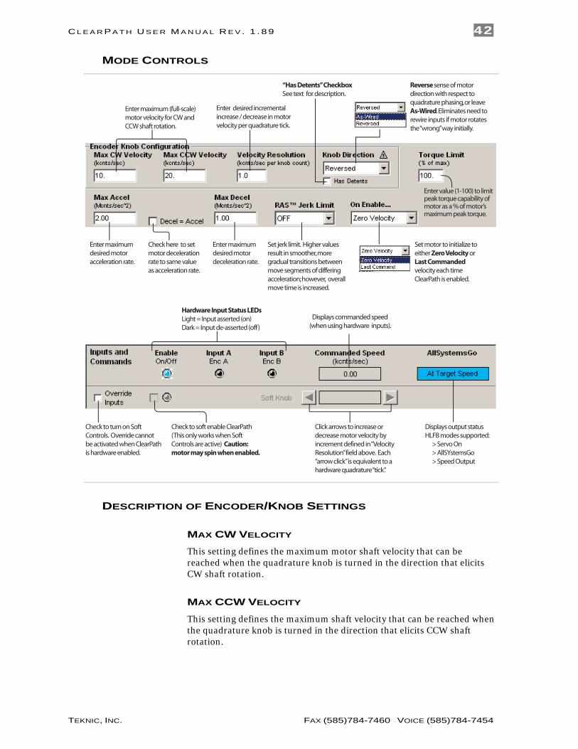
MODE CONTROLS
Enter maximum (full-scale) motor velocity for CW and CCW shaft rotation.
Enter maximum desired motor acceleration rate.
Check here to set motor deceleration rate to same value as acceleration rate.
Check to turn on Soft Controls. Override cannot be activated when ClearPath is hardware enabled.
Check to soft enable ClearPath (This only works when Soft Controls are active) Caution: motor may spin when enabled.
Click arrows to increase or decrease motor velocity by increment defined in “Velocity Resolution” field above. Each “arrow click” is equivalent to a hardware quadrature “tick”.
Displays output statusHLFB modes supported: > Servo On > AllSYstemsGo > Speed Output
Enter maximum desired motor deceleration rate.
Enter value (1-100) to limit peak torque capability of motor as a % of motor’s maximum peak torque.
Displays commanded speed (when using hardware inputs).
Set motor to initialize to either Zero Velocity or Last Commanded velocity each time ClearPath is enabled.
Enter desired incremental increase / decrease in motor velocity per quadrature tick.
Reverse sense of motor direction with respect to quadrature phasing, or leave As-Wired. Eliminates need to rewire inputs if motor rotates the “wrong” way initially.
Hardware Input Status LEDsLight = Input asserted (on)Dark = Input de-asserted (off)
Set jerk limit. Higher values result in smoother, more gradual transitions between move segments of differing acceleration; however, overall move time is increased.
“Has Detents” CheckboxSee text for description.
DESCRIPTION OF ENCODER/KNOB SETTINGS
MAX CW VELOCITY
This setting defines the maximum motor shaft velocity that can be reached when the quadrature knob is turned in the direction that elicits CW shaft rotation.
MAX CCW VELOCITY
This setting defines the maximum shaft velocity that can be reached when the quadrature knob is turned in the direction that elicits CCW shaft rotation.

C L E A R P A T H U S E R M A N U A L R E V . 1 . 8 9 43
TEKNIC, INC. FAX (585)784-7460 VOICE (585)784-7454
VELOCITY RESOLUTION
This setting defines exactly how much (i.e., by what increment) motor velocity will increase or decrease per quadrature “tick”.
KNOB DIRECTION
These setting allow the user to reverse the motor’s sense of direction with respect to the quadrature device.
“HAS DETENTS” CHECKBOX
When unchecked, ClearPath treats each quadrature transition it sees at its inputs as a single “tick”. (Remember, each tick causes an incremental increase or decrease in motor speed.)
When checked, ClearPath treats every 4th quadrature transition it sees at its inputs as one “tick”. (Remember, each “tick” causes an incremental increase or decrease in motor speed.) Check this box when using an encoder that has one detent point per full quadrature cycle or if you want to divide your quadrature resolution by four.

C L E A R P A T H U S E R M A N U A L R E V . 1 . 8 9 44
TEKNIC, INC. FAX (585)784-7460 VOICE (585)784-7454
RAMP UP/DOWN TO SELECTED VELOCITY.
MODE SUMMARY Changing the digital inputs on ClearPath (from your PLC, switches, etc.) causes ClearPath to smoothly ramp to any of four preset velocities.
HOW IT WORKS Assign up to four target velocities where positive values cause CCW motion and negative values cause CW motion.
Assert the Enable Input to start. Once enabled, ClearPath immediately accelerates to the target velocity indicated by the state of Inputs A and B. For example, if Input A=high and Input B=low, ClearPath ramps to “Velocity 2”. Change velocity by changing Inputs A and/or B.
Signal Function Velocity Settings (logic levels) Example Timing
Input A
Motor velocity vs. time
Input B
Enable
Velocity Select A
Velocity Select B
Enable
NA NATrigger
Logic: High=Enable Low=Disable 0
1
0
1
0
1
0
1
t
v0
Velocity 1 Velocity 2 Velocity 3 Velocity 4
LOW
LOW
HIGH
LOW
LOW
HIGH
HIGH
HIGH
Tip: Setting one of the programmable velocities to zero (Velocity 3 in the example at right) provides a convenient way to stop the motor via the ClearPath inputs.
Velocity 1Velocity 2
Velocity 3
Velocity 4
Ramp Up/Down to Selected Velocity (4 Velocity Programmable)Velocity Control
Ramp Up/Down to Selected Velocity Mode: Inputs and Timing Diagram
Notes:
• As soon as a new velocity command is received by ClearPath—as happens when Inputs A and/or B are changed—ClearPath smoothly ramps to the new target velocity without delay.
• If you need a convenient way to command ClearPath to stop via the inputs, set one of the velocity settings to zero. We did this with “Velocity 3” in the table above.
• Disable time = 10 mS

C L E A R P A T H U S E R M A N U A L R E V . 1 . 8 9 45
TEKNIC, INC. FAX (585)784-7460 VOICE (585)784-7454
MODE CONTROLS
Enter maximum desired motor acceleration rate.
Enter target velocity for each input state here.
Check here to set motor deceleration rate to same value as acceleration rate.
Soft Inputs and LEDs emulate hardware inputs. For use only when Soft Controls are active. Caution: motor may spin when enabled.
Enter maximum desired motor deceleration rate..
Displays commanded velocity (when using hard inputs).
Displays commanded velocity (when using soft inputs).
Hardware Input Status LEDsLight = Input asserted (on)Dark = Input de-asserted (off)
Displays output status.HLFB modes supported: >Servo On >AllSystemsGo
Check to turn on Soft Controls. Override cannot be activated when ClearPath is hardware enabled.
Enter value (1-100) to limit peak torque capability of motor as a % of motor’s maximum peak torque.
Set jerk limit. Higher values result in smoother, more gradual transitions between move segments of differing acceleration; however, overall move time is increased.
C L E A R P A T H U S E R M A N U A L R E V . 1 . 8 9 46
TEKNIC, INC. FAX (585)784-7460 VOICE (585)784-7454
FOLLOW DIGITAL VELOCITY COMMAND (BI-POLAR PWM INPUT) .
MODE SUMMARY Connect a digital PWM waveform from your PLC or other device, and ClearPath will run at a velocity proportional to the duty cycle of that waveform. Or, use the PWM output from an H-bridge driver of a brushed motor setup and ClearPath becomes a high-performance drop-in replacement.
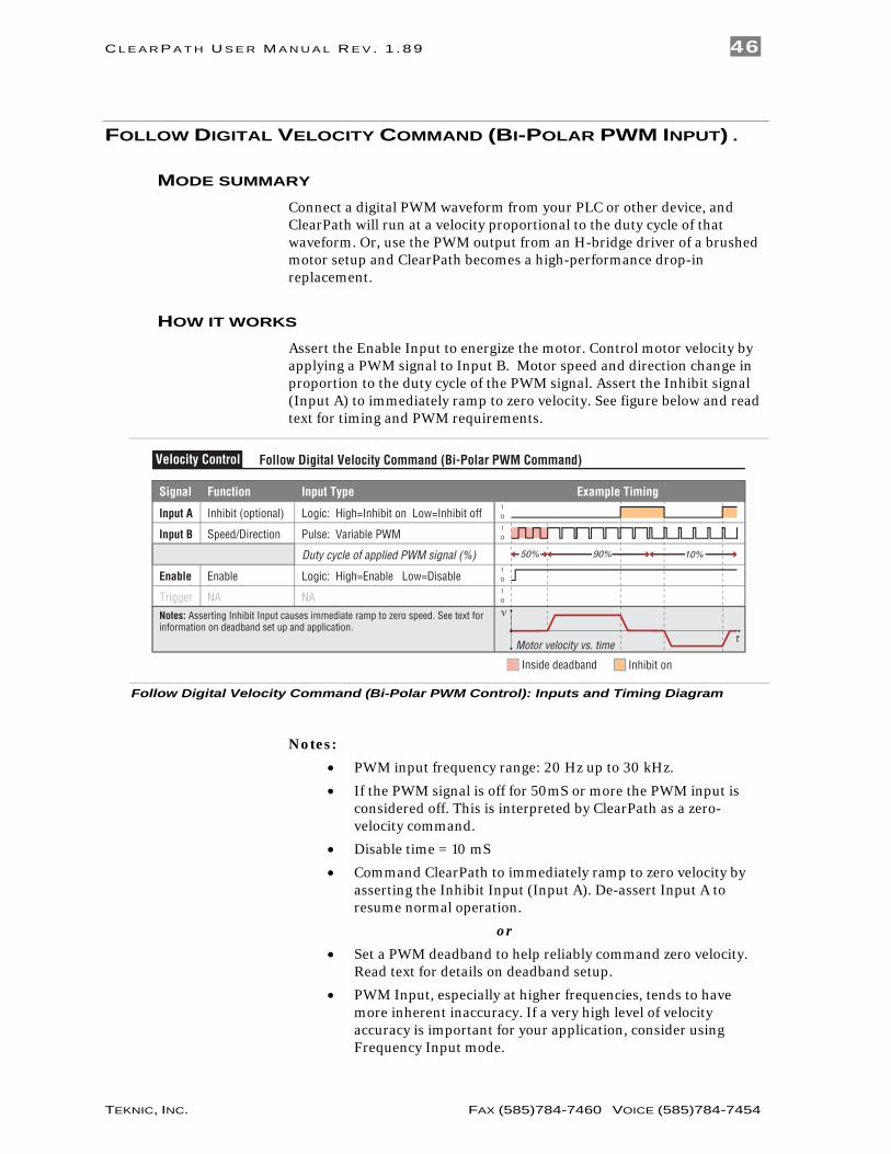
HOW IT WORKS Assert the Enable Input to energize the motor. Control motor velocity by applying a PWM signal to Input B. Motor speed and direction change in proportion to the duty cycle of the PWM signal. Assert the Inhibit signal (Input A) to immediately ramp to zero velocity. See figure below and read text for timing and PWM requirements.
Signal Function Input Type
Input A
Motor velocity vs. time
Input B
Enable
Inhibit (optional)
Speed/Direction
Enable
NA NATrigger
Logic: High=Inhibit on Low=Inhibit off
Pulse: Variable PWM
Logic: High=Enable Low=Disable
0
1
0
1
t
v
Example Timing
Notes: Asserting Inhibit Input causes immediate ramp to zero speed. See text forinformation on deadband set up and application.
0
1
0
1
Inside deadband Inhibit on
Duty cycle of applied PWM signal (%)
Follow Digital Velocity Command (Bi-Polar PWM Command)Velocity Control
90%50% 10%
Follow Digital Velocity Command (Bi-Polar PWM Control): Inputs and Timing Diagram
Notes:
• PWM input frequency range: 20 Hz up to 30 kHz.
• If the PWM signal is off for 50mS or more the PWM input is considered off. This is interpreted by ClearPath as a zero-velocity command.
• Disable time = 10 mS
• Command ClearPath to immediately ramp to zero velocity by asserting the Inhibit Input (Input A). De-assert Input A to resume normal operation.
or
• Set a PWM deadband to help reliably command zero velocity. Read text for details on deadband setup.
• PWM Input, especially at higher frequencies, tends to have more inherent inaccuracy. If a very high level of velocity accuracy is important for your application, consider using Frequency Input mode.

C L E A R P A T H U S E R M A N U A L R E V . 1 . 8 9 47
TEKNIC, INC. FAX (585)784-7460 VOICE (585)784-7454
MODE CONTROLS
Enter maximum desired motor acceleration rate.
Enter deadband setting (optional). See text for description of deadband operation.
Enter maximummotor speed (i.e. full scale speed).
Check here to set motor deceleration rate to same value as acceleration rate.
Soft Inputs and LEDs Emulate hardware inputs. For use only when Soft Controls are active. Caution: motor may spin when enabled.
Enter maximum desired motor deceleration rate..
Displays commanded velocity (when using Soft Controls).
Displays commanded velocity (when using hard controls).
Hardware Input Status LEDsLight = Input asserted (on)Dark = Input de-asserted (off)
PWM Meter - Displays duty cycle of PWM source connected to Input B.
PWM Soft SliderEmulates PWM input (for use with Soft Controls).
Displays output statusHLFB modes supported: >Servo On >AllSystemsGo >Speed Output
Check to turn on Soft Controls. Override cannot be activated when ClearPath is hardware enabled.
Enter value (1-100) to limit peak torque capability of motor as a % of motor’s maximum peak torque.
Set jerk limit. Higher values result in smoother, more gradual transitions between move segments of differing acceleration; however, overall move time is increased.

C L E A R P A T H U S E R M A N U A L R E V . 1 . 8 9 48
TEKNIC, INC. FAX (585)784-7460 VOICE (585)784-7454
Relationship of PWM duty cycle to motor velocity
• Shaft velocity increases in the CW direction as PWM duty cycle decreases from 50% to 0%
• Shaft velocity increases in the CCW direction as PWM duty cycle increases from 50% to 100%
• As PWM duty cycle approaches 50%—from either direction—motor velocity approaches 0.
• In practice, O% and 100% (static low and static high conditions) are not valid PWM states. ClearPath treats these cases as zero-velocity commands.
• PWM minimum on time and minimum off time = 300nS.
Max. Velocity(CCW Rotation)
Velocity = 0
ZeroVelocity
10 20 30 40 50 60 70 80 90 1000
Max. Velocity(CW Rotation)
Duty Cycle
Graph of PWM duty cycle vs. motor velocity

C L E A R P A T H U S E R M A N U A L R E V . 1 . 8 9 49
TEKNIC, INC. FAX (585)784-7460 VOICE (585)784-7454
SETTING A PWM DEADBAND (OPTIONAL) The deadband expands the range about the 50% PWM mark that is interpreted as the “zero-velocity setting” by ClearPath. This gives the user a reliable way to ensure that motor velocity ramps to zero when the PWM duty cycle is set at (or “close enough” to) 50%.
Max. Velocity(CCW Rotation)
Velocity = 0Deadband(+/- 5%)
10 20 30 40 50 60 70 80 90 1000
Max. Velocity(CW Rotation)
Duty Cycle
+/- 5% PWM dead band setting
Why use a deadband?
In bi-polar mode, stopping the motor (i.e. commanding “zero velocity”) is achieved, in theory, by applying a 50% duty cycle PWM signal to Input B. However, it can be technically challenging to set a perfect 50% duty cycle. In fact, some very low speed motion may still be observed at the motor shaft even when duty cycle is apparently set to 50%. A deadband helps to ensure that actual motor velocity is zero (with no drift) when you expect it to be.
Example: If the user sets a +/- 5% dead band, any PWM signal with a duty cycle between 45% and 55% will be interpreted as a zero-velocity command by ClearPath. See figure above.
Note: As size of deadband setting increases, the slope of velocity vs. duty cycle increases as illustrated below.
C L E A R P A T H U S E R M A N U A L R E V . 1 . 8 9 50
TEKNIC, INC. FAX (585)784-7460 VOICE (585)784-7454
FOLLOW DIGITAL VELOCITY COMMAND (UNIPOLAR PWM INPUT) .
MODE SUMMARY Connect a digital PWM waveform from your PLC or other device, and ClearPath will run at a speed proportional to the duty cycle of the PWM waveform.
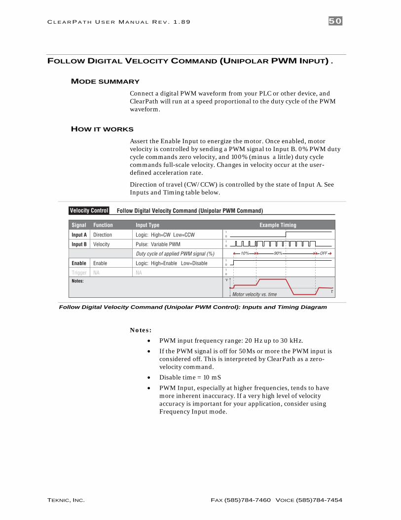
HOW IT WORKS Assert the Enable Input to energize the motor. Once enabled, motor velocity is controlled by sending a PWM signal to Input B. 0% PWM duty cycle commands zero velocity, and 100% (minus a little) duty cycle commands full-scale velocity. Changes in velocity occur at the user-defined acceleration rate.
Direction of travel (CW/CCW) is controlled by the state of Input A. See Inputs and Timing table below.
Signal Function Input Type
Input A
Motor velocity vs. time
Input B
Enable
Direction
Velocity
Enable
NA NATrigger
Logic: High=CW Low=CCW
Pulse: Variable PWM
Logic: High=Enable Low=Disable
0
1
0
1
t
v
Example Timing
Notes:
0
1
0
1
Duty cycle of applied PWM signal (%) 90%10% OFF
Follow Digital Velocity Command (Unipolar PWM Command)Velocity Control
Follow Digital Velocity Command (Unipolar PWM Control): Inputs and Timing Diagram
Notes:
• PWM input frequency range: 20 Hz up to 30 kHz.
• If the PWM signal is off for 50Ms or more the PWM input is considered off. This is interpreted by ClearPath as a zero-velocity command.
• Disable time = 10 mS
• PWM Input, especially at higher frequencies, tends to have more inherent inaccuracy. If a very high level of velocity accuracy is important for your application, consider using Frequency Input mode.
C L E A R P A T H U S E R M A N U A L R E V . 1 . 8 9 51
TEKNIC, INC. FAX (585)784-7460 VOICE (585)784-7454
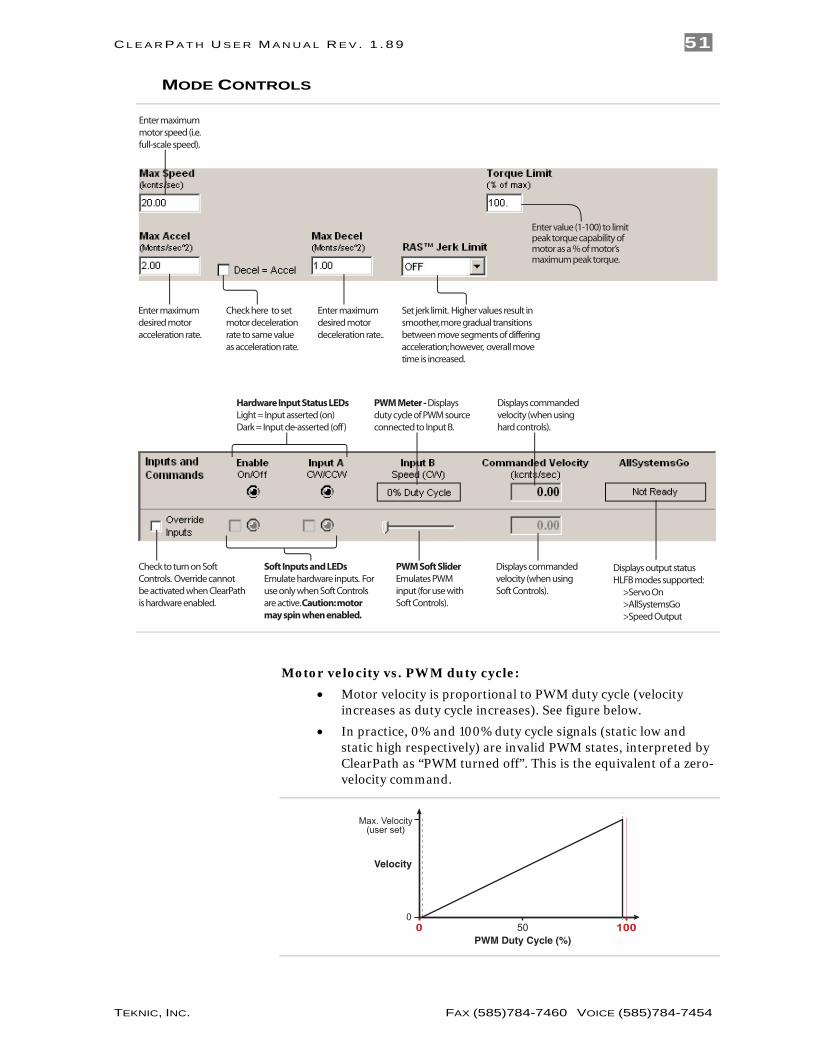
MODE CONTROLS
Enter maximum desired motor acceleration rate.
Enter maximummotor speed (i.e. full-scale speed).
Check here to set motor deceleration rate to same value as acceleration rate.
Soft Inputs and LEDs Emulate hardware inputs. For use only when Soft Controls are active. Caution: motor may spin when enabled.
Enter maximum desired motor deceleration rate..
Displays commanded velocity (when using Soft Controls).
Displays commanded velocity (when using hard controls).
Hardware Input Status LEDsLight = Input asserted (on)Dark = Input de-asserted (off)
PWM Meter - Displays duty cycle of PWM source connected to Input B.
PWM Soft SliderEmulates PWM input (for use with Soft Controls).
Displays output statusHLFB modes supported: >Servo On >AllSystemsGo >Speed Output
Check to turn on Soft Controls. Override cannot be activated when ClearPath is hardware enabled.
Enter value (1-100) to limit peak torque capability of motor as a % of motor’s maximum peak torque.
Set jerk limit. Higher values result in smoother, more gradual transitions between move segments of differing acceleration; however, overall move time is increased.
Motor velocity vs. PWM duty cycle:
• Motor velocity is proportional to PWM duty cycle (velocity increases as duty cycle increases). See figure below.
• In practice, 0% and 100% duty cycle signals (static low and static high respectively) are invalid PWM states, interpreted by ClearPath as “PWM turned off”. This is the equivalent of a zero-velocity command.
0 50 100PWM Duty Cycle (%)
Velocity
Max. Velocity(user set)
0

C L E A R P A T H U S E R M A N U A L R E V . 1 . 8 9 52
TEKNIC, INC. FAX (585)784-7460 VOICE (585)784-7454
• For CW shaft rotation, set Input A high. For CCW shaft rotation, set Input A low.
• PWM minimum on time and minimum off time = 300nS

C L E A R P A T H U S E R M A N U A L R E V . 1 . 8 9 53
TEKNIC, INC. FAX (585)784-7460 VOICE (585)784-7454
FOLLOW DIGITAL VELOCITY COMMAND (FREQUENCY INPUT) .
MODE SUMMARY Connect a digital variable frequency waveform from your PLC or other device, and ClearPath will run at a velocity proportional to the frequency of the waveform.
HOW IT WORKS Assert the Enable Input to energize the motor. Then, control velocity by applying a variable frequency pulse train to Input B. Pulse frequency is proportional to commanded velocity. Direction of travel (CW/CCW) is controlled by the state of Input A. See Inputs and Timing table below.
Signal Function Input Type
Input A
Motor velocity vs. time
Input B
Enable
Direction
Velocity
Enable
NA NATrigger
Logic: High=CW Low=CCW
Pulse: Variable Frequency
Logic: High=Enable Low=Disable
0
1
0
1
t
v
Example Timing
Notes:
0
1
0
1
Follow Digital Velocity Command (Frequency Input Control)Velocity Control
Follow Digital Velocity Command (Frequency Input Control): Inputs and Timing Diagram
Notes:
• Input frequency range: 20 Hz to 500 kHz.
• If the frequency signal is off for 50mS or more the input is considered off. This is interpreted by ClearPath as a zero-velocity command.
• Disable time = 10 mS

C L E A R P A T H U S E R M A N U A L R E V . 1 . 8 9 54
TEKNIC, INC. FAX (585)784-7460 VOICE (585)784-7454
MODE CONTROLS
Enter maximum desired motor acceleration rate.
Enter maximummotor speed (i.e. full scale speed).
Check here to set motor deceleration rate to same value as acceleration rate.
Set Min/Max Frequency. During operation, motor speed is controlled by Input B signal frequency. With the settings below, a 30 kHz signal at Input B will cause the motor to spin at the Max Speed setting (20 kcounts/sec); a 1 kHz signal will command zero speed.
Soft Inputs and LEDs Emulate hardware inputs. For use only when Soft Controls are active. Caution: motor may spin when enabled.
Enter maximum desired motor deceleration rate..
Displays commanded velocity (when using Soft Controls).
Displays commanded velocity (when using hard controls).
Hardware Input Status LEDsLight = Input asserted (on)Dark = Input de-asserted (off)
Frequency Meter Displays frequency of input signal source connected to Input B.
Frequency Soft SliderEmulates frequency input source (for use with Soft Controls).
Displays output statusHLFB modes supported: >Servo On >AllSystemsGo >Speed Output
Check to turn on Soft Controls. Override cannot be activated when ClearPath is hardware enabled.
Enter value (1-100) to limit peak torque capability of motor as a % of motor’s maximum peak torque.
Set jerk limit. Higher values result in smoother, more gradual transitions between move segments of differing acceleration; however, overall move time is increased.

C L E A R P A T H U S E R M A N U A L R E V . 1 . 8 9 55
TEKNIC, INC. FAX (585)784-7460 VOICE (585)784-7454
FOLLOW DIGITAL TORQUE COMMAND (BI-POLAR PWM INPUT) .
MODE SUMMARY Connect a digital PWM waveform from your PLC or other device, and ClearPath will produce torque proportional to the duty cycle of the PWM waveform.
HOW IT WORKS Assert the Enable Input to energize the motor. Control motor torque by applying a PWM signal to Input B. Motor torque changes in proportion to the duty cycle of the applied PWM signal. Assert the Inhibit signal (Input A) to immediately turn off torque. See figure below and read text for timing and PWM requirements.
Signal Function Input Type
Input A
Motor torque vs. time
Input B
Enable
Inhibit (optional)
Torque/Direction
Enable
NA NATrigger
Logic: High=Inhibit on Low=Inhibit off
Pulse: Variable PWM
Logic: High=Enable Low=Disable
0
1
0
1
t
tq
Example Timing
Notes: Asserting Inhibit Input causes immediate jump to zero torque. See text forinformation on deadband set up and application.
0
1
0
1
Inside deadband Inhibit on
Duty cycle of applied PWM signal (%)
Follow Digital Torque Command (Bi-Polar PWM Command)Torque Control
90%50% 20%
Follow Digital Torque Command (Bi-polar PWM Control): Inputs and Timing Diagram
Notes:
• PWM input frequency range: 20 Hz to 30 kHz.
• If the PWM signal is off for 50mS (or more) the PWM input is considered off. This is interpreted by ClearPath as a zero-torque command.
• Disable time = 10 mS
• To command ClearPath to zero torque, assert the Inhibit Input (Input A). De-assert Input A to resume normal operation.
or
• Set a PWM deadband to help reliably command zero torque. Refer to text on following pages for details on deadband setup.

C L E A R P A T H U S E R M A N U A L R E V . 1 . 8 9 56
TEKNIC, INC. FAX (585)784-7460 VOICE (585)784-7454
MODE CONTROLS
Enter deadband setting (optional). See text for description of deadband.
Enter maximum speed. ClearPath will shut down if this speed limit is exceeded.
Enter maximummotor torque (i.e. full scale torque).
Soft Inputs and LEDs Emulate hardware inputs. For use only when Soft Controls are active. Caution: motor may spin when enabled.
Displays commanded torque (when using Soft Controls).
Displays commanded torque (when using hard controls).
Hardware Input Status LEDsLight = Input asserted (on)Dark = Input de-asserted (off)
PWM Meter - Displays duty cycle of PWM source connected to Input B.
PWM Soft SliderEmulates PWM input (for use with Soft Controls).
Displays output statusHLFB modes supported: >Servo On >AllSystemsGo >Speed Output
Check to turn on Soft Controls. Override cannot be activated when ClearPath is hardware enabled.
Enter value in mS. Determines how long ClearPath can spin at max speed before shutting down.
C L E A R P A T H U S E R M A N U A L R E V . 1 . 8 9 57
TEKNIC, INC. FAX (585)784-7460 VOICE (585)784-7454
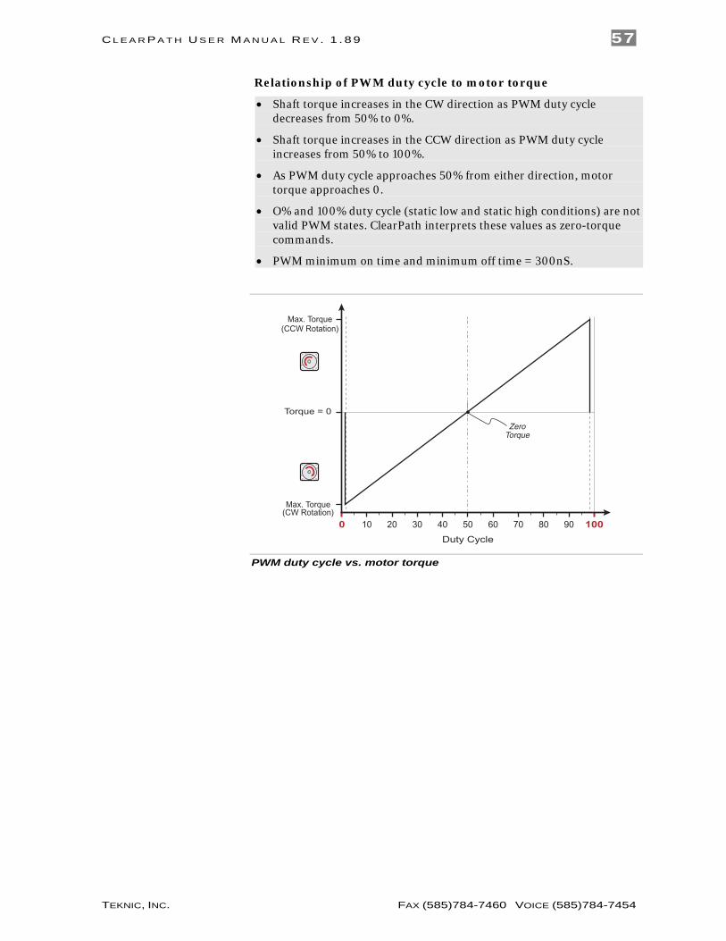
Relationship of PWM duty cycle to motor torque
• Shaft torque increases in the CW direction as PWM duty cycle decreases from 50% to 0%.
• Shaft torque increases in the CCW direction as PWM duty cycle increases from 50% to 100%.
• As PWM duty cycle approaches 50% from either direction, motor torque approaches 0.
• O% and 100% duty cycle (static low and static high conditions) are not valid PWM states. ClearPath interprets these values as zero-torque commands.
• PWM minimum on time and minimum off time = 300nS.
Max. Torque(CCW Rotation)
Torque = 0
ZeroTorque
10 20 30 40 50 60 70 80 90 1000
Max. Torque(CW Rotation)
Duty Cycle
PWM duty cycle vs. motor torque

C L E A R P A T H U S E R M A N U A L R E V . 1 . 8 9 58
TEKNIC, INC. FAX (585)784-7460 VOICE (585)784-7454
SETTING A PWM DEADBAND (OPTIONAL) The deadband expands the range about the 50% PWM mark that is interpreted as the “zero torque setting” by ClearPath. This gives the user a reliable way to ensure that motor torque is completely turned off when the PWM duty cycle is set at (or “close enough” to) 50%.
Max. Torque(CCW Rotation)
Torque = 0
Duty Cycle
Deadband(+/- 5%)
10 20 30 40 50 60 70 80 90 1000
Max. Torque(CW Rotation)
+/- 5% PWM deadband setting
Why use a deadband?
In bi-polar mode, turning off torque is achieved, in theory, by applying a 50% duty cycle PWM signal to Input B. However, it can be difficult to set a perfect 50% duty cycle. In fact, a very small amount of torque may still be produced by the motor, even when duty cycle is apparently set to 50%. A deadband helps guarantee torque is fully off when you expect it to be.
Example: If the user sets a +/-5% deadband, any PWM signal with a duty cycle between 45% and 55% (i.e., in the deadband) is interpreted as a zero-torque command by ClearPath.
Note: As deadband setting increases, the slope of torque vs. duty cycle increases as illustrated below.
C L E A R P A T H U S E R M A N U A L R E V . 1 . 8 9 59
TEKNIC, INC. FAX (585)784-7460 VOICE (585)784-7454
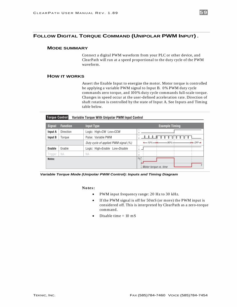
FOLLOW DIGITAL TORQUE COMMAND (UNIPOLAR PWM INPUT) .
MODE SUMMARY Connect a digital PWM waveform from your PLC or other device, and ClearPath will run at a speed proportional to the duty cycle of the PWM waveform.
HOW IT WORKS Assert the Enable Input to energize the motor. Motor torque is controlled be applying a variable PWM signal to Input B. 0% PWM duty cycle commands zero torque, and 100% duty cycle commands full-scale torque. Changes in speed occur at the user-defined acceleration rate. Direction of shaft rotation is controlled by the state of Input A. See Inputs and Timing table below.
Signal Function Input Type
Input A
Motor torque vs. time
Input B
Enable
Direction
Torque
Enable
NA NATrigger
Logic: High=CW Low=CCW
Pulse: Variable PWM
Logic: High=Enable Low=Disable
0
1
0
1
t
tq
Example Timing
Notes:
0
1
0
1
Duty cycle of applied PWM signal (%) 90%10% OFF
Variable Torque With Unipolar PWM Input ControlTorque Control
Variable Torque Mode (Unipolar PWM Control): Inputs and Timing Diagram
Notes:
• PWM input frequency range: 20 Hz to 30 kHz.
• If the PWM signal is off for 50mS (or more) the PWM input is considered off. This is interpreted by ClearPath as a zero-torque command.
• Disable time = 10 mS

C L E A R P A T H U S E R M A N U A L R E V . 1 . 8 9 60
TEKNIC, INC. FAX (585)784-7460 VOICE (585)784-7454
MODE CONTROLS
Enter maximum speed. ClearPath will shut down if this speed limit is exceeded.
Enter maximummotor torque (i.e. full scale torque).
Soft Inputs and LEDs Emulate hardware inputs. For use only when Soft Controls are active. Caution: motor may spin when enabled.
Displays commanded torque (when using Soft Controls).
Displays commanded torque (when using hard controls).
Hardware Input Status LEDsLight = Input asserted (on)Dark = Input de-asserted (off)
PWM Meter - Displays duty cycle of PWM source connected to Input B.
PWM Soft SliderEmulates PWM input (for use with Soft Controls).
Displays output statusHLFB modes supported: >Servo On >AllSystemsGo >Speed Output
Check to turn on Soft Controls. Override cannot be activated when ClearPath is hardware enabled.
Enter value in mS. Determines how long ClearPath can spin at max speed before shutting down.
Motor torque vs. PWM duty cycle:
• Motor torque is proportional to PWM duty cycle (i.e. torque increases as duty cycle increases). See figure below.
• 0% and 100% duty cycle signals (static low and static high respectively) are invalid PWM states, interpreted by ClearPath as “PWM turned off”. This is the equivalent of a zero-torque command.
0 50 100PWM Duty Cycle (%)
Torque
Max. Torque(user set)
0
PWM duty cycle vs. torque
• For CW torque, set Input A high. For CCW torque, set Input A low.
• PWM minimum on time and minimum off time = 300nS

C L E A R P A T H U S E R M A N U A L R E V . 1 . 8 9 61
TEKNIC, INC. FAX (585)784-7460 VOICE (585)784-7454
FOLLOW DIGITAL TORQUE COMMAND (FREQUENCY INPUT) .
MODE SUMMARY Connect a digital variable frequency waveform from your PLC or other device, and ClearPath will produce torque that is proportional to the frequency of the waveform.
HOW IT WORKS Assert the Enable Input to energize the motor. Control torque by applying a variable frequency pulse train to Input B. Pulse frequency is proportional to commanded torque. Direction in which torque is applied (CW/CCW) is controlled by the state of Input A. See Inputs and Timing table below.
Signal Function Input Type
Input A
Motor torque vs. time
Input B
Enable
Direction
Torque
Enable
NA NATrigger
Logic: High=CW Low=CCW
Pulse: Variable Frequency
Logic: High=Enable Low=Disable
0
1
0
1
t
tq
Example Timing
Notes:
0
1
0
1
Variable Torque With Frequency Input ControlTorque Control
Variable Torque Mode (Frequency Control): Inputs and Timing Diagram
Notes:
• Input frequency range: 20 Hz to 500 kHz.
• If the frequency signal is off for 50mS or more the input is considered off. This is interpreted by ClearPath as a zero-torque command.
• Disable time = 10 mS

C L E A R P A T H U S E R M A N U A L R E V . 1 . 8 9 62
TEKNIC, INC. FAX (585)784-7460 VOICE (585)784-7454
MODE CONTROLS
Enter maximummotor torque (i.e. full scale torque).
Soft Inputs and LEDs Emulate hardware inputs. For use only when Soft Controls are active. Caution: motor may spin when enabled.
Displays commanded torque (when using Soft Controls).
Displays commanded torque (when using hard controls).
Hardware Input Status LEDsLight = Input asserted (on)Dark = Input de-asserted (off)
Frequency Meter Displays frequency of signal source connected to Input B.
Frequency Soft SliderEmulates frequency input (for use with Soft Controls).
Displays output statusHLFB modes supported: >Servo On >AllSystemsGo >Speed Output
Check to turn on Soft Controls. Override cannot be activated when ClearPath is hardware enabled.
Enter maximum speed. ClearPath will shut down if this speed limit is exceeded.
Enter value in mS. Determines how long ClearPath can spin at max speed before shutting down.
Set Min/Max Frequency. During operation, motor torque is controlled by Input B signal frequency. With the settings below, a 30 kHz input signal will command the motor to the Max Torque setting (25% of peak ); a 1 kHz signal will command zero torque.

C L E A R P A T H U S E R M A N U A L R E V . 1 . 8 9 63
TEKNIC, INC. FAX (585)784-7460 VOICE (585)784-7454
MOVE TO ABSOLUTE POSITION (2-POSITION) .
MODE SUMMARY Trigger ClearPath to move to one of two preset locations. This mode was designed for replacing hydraulic or pneumatic cylinders that move between two positions.
HOW IT WORKS. Assert the Enable Input to energize the motor. Once enabled, ClearPath automatically executes a homing move to a [user-supplied] switch or sensor wired to Input B. Once a home position is established, ClearPath automatically moves to one of the two user-defined positions (based on the state of Input A). After that, just toggle Input A to move between the two target positions.
Absolute Position
An absolute position is referenced to an established “home” position. Your target positions, in this context, are defined in terms of distance from the home position. For example, Position 1 could be defined as 5200 encoder counts from home, while Position 2 might be defined as 2000 encoder counts from home.
Signal Function Input Type
Input A
Motor position vs. time
Input B
Enable
Position Select
Home Switch
Enable
NA NATrigger
Logic: High=Pos. 2 Low=Pos. 1
Logic: High=Home Low= Not Home
Logic: High=Enable Low=Disable
0
1
0
1
t
p+
p-
Example Timing
Notes: ClearPath must home to a switch upon enable to establish the Home (zero) position to which the other target positions are referenced.
0
1
0
1
Pos 1
HomePos 2 Pos 2
Pos 1
Absolute Position (2-Position Programmable)Position Control
Absolute Position Mode (2): Inputs and Timing Diagram
Notes:
• If the state of Input A is changed during a move, ClearPath will immediately ramp to a stop and move to the newly indicated position.
• Input B switch polarity can be inverted via a checkbox in the Homing Setup dialog. When home switch polarity is inverted, ClearPath interprets Input B-low as “in the home switch”, and Input B-high as “not in the home switch”.
• Disable time = 10 mS
C L E A R P A T H U S E R M A N U A L R E V . 1 . 8 9 64
TEKNIC, INC. FAX (585)784-7460 VOICE (585)784-7454
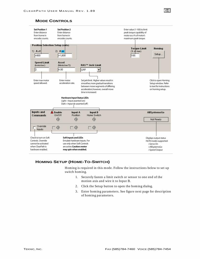
MODE CONTROLS
Enter max motor speed allowed.
Soft Inputs and LEDs Emulate hardware inputs. For use only when Soft Controls are active. Caution: motor may spin when enabled.
Enter motor acceleration rate.
Hardware Input Status LEDsLight = Input asserted (on)Dark = Input de-asserted (off)
Click to open Homing Setup window. Refer to text for instructions on homing setup.
Displays output statusHLFB modes supported: >Servo On >AllSystemsGo >Speed Output
Check to turn on Soft Controls. Override cannot be activated when ClearPath is hardware enabled.
Enter value (1-100) to limit peak torque capability of motor as a % of motor’s maximum peak torque.
Set Position 1 Enter distance from home in encoder counts.
Set Position 2Enter distance from home in encoder counts.
Set jerk limit. Higher values result in smoother, more gradual transitions between move segments of differing acceleration; however, overall move time is increased.
HOMING SETUP (HOME-TO-SWITCH) Homing is required in this mode. Follow the instructions below to set up switch homing.
1. Securely fasten a limit switch or sensor to one end of the motion axis and wire it to Input B.
2. Click the Setup button to open the homing dialog.
3. Enter homing parameters. See figure next page for description of homing parameters.

C L E A R P A T H U S E R M A N U A L R E V . 1 . 8 9 65
TEKNIC, INC. FAX (585)784-7460 VOICE (585)784-7454
Homing setup dialog
4. Test and modify your homing setup for proper performance.
How Switch Homing Works:
• During homing, the axis is automatically driven toward the homing switch at the user-specified direction and speed.
• Once the switch is actuated, the motor ramps to a stop and the encoder position counter is zeroed. This position is now considered the home reference position.
C L E A R P A T H U S E R M A N U A L R E V . 1 . 8 9 66
TEKNIC, INC. FAX (585)784-7460 VOICE (585)784-7454
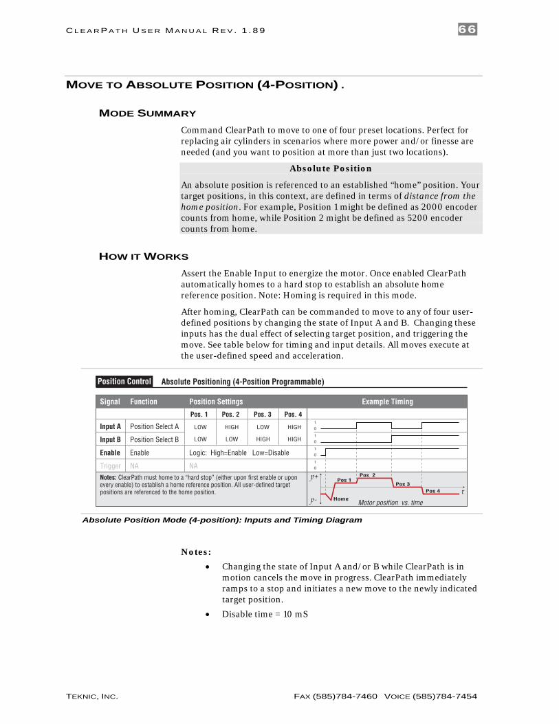
MOVE TO ABSOLUTE POSITION (4-POSITION) .
MODE SUMMARY Command ClearPath to move to one of four preset locations. Perfect for replacing air cylinders in scenarios where more power and/or finesse are needed (and you want to position at more than just two locations).
Absolute Position
An absolute position is referenced to an established “home” position. Your target positions, in this context, are defined in terms of distance from the home position. For example, Position 1 might be defined as 2000 encoder counts from home, while Position 2 might be defined as 5200 encoder counts from home.
HOW IT WORKS Assert the Enable Input to energize the motor. Once enabled ClearPath automatically homes to a hard stop to establish an absolute home reference position. Note: Homing is required in this mode.
After homing, ClearPath can be commanded to move to any of four user-defined positions by changing the state of Input A and B. Changing these inputs has the dual effect of selecting target position, and triggering the move. See table below for timing and input details. All moves execute at the user-defined speed and acceleration.
Signal Function Position Settings Example Timing
Input A
Motor position vs. time
Input B
Enable
Position Select A
Position Select B
Enable
NA NATrigger
Logic: High=Enable Low=Disable 0
1
0
1
0
1
0
1
t
p+
p-
Pos. 1 Pos. 2 Pos. 3 Pos. 4
LOW
LOW
HIGH
LOW
LOW
HIGH
HIGH
HIGH
Notes: ClearPath must home to a “hard stop” (either upon first enable or upon every enable) to establish a home reference position. All user-defined target positions are referenced to the home position.
Pos 1
Home
Pos 2
Pos 3Pos 4
Absolute Positioning (4-Position Programmable)Position Control
Absolute Position Mode (4-position): Inputs and Timing Diagram
Notes:
• Changing the state of Input A and/or B while ClearPath is in motion cancels the move in progress. ClearPath immediately ramps to a stop and initiates a new move to the newly indicated target position.
• Disable time = 10 mS

C L E A R P A T H U S E R M A N U A L R E V . 1 . 8 9 67
TEKNIC, INC. FAX (585)784-7460 VOICE (585)784-7454
MODE CONTROLS
Enter maximum motor speed allowed.
Enter motor acceleration rate.
Soft Inputs and LEDs emulate hardware inputs. For use only when Soft Controls are active. Caution: motor may spin when enabled.
Click during homing operation to manually set home position.
Hardware Input Status LEDsLight = Input asserted (on)Dark = Input de-asserted (off)
Displays output status.HLFB modes supported: >Servo On >AllSystemsGo >Speed Output
Check to turn on Soft Controls. Override cannot be activated when ClearPath is hardware enabled.
Enter value (1-100) to limit peak torque capability of motor as a % of motor’s maximum peak torque.
Set Target PositionsEnter move distance (from home) for each input state.
Set jerk limit. Higher values result in smoother, more gradual transitions between move segments of differing acceleration; however, overall move time is increased.
Click to open Homing Setup window. Refer to text for instructions on homing setup.
HOMING SETUP (HARD STOP HOMING) In this mode, ClearPath must home to a hard stop to establish a home reference position before functional positioning can begin.
1. Install a hard stop that guarantees the moving element of the axis will make solid, repeatable contact with the stationary element when driven into it.
2. Click the Setup button to open the homing dialog.
3. Enter homing parameters. See figure next page for description of homing parameters.

C L E A R P A T H U S E R M A N U A L R E V . 1 . 8 9 68
TEKNIC, INC. FAX (585)784-7460 VOICE (585)784-7454
Homing setup dialog
4. Test and modify your homing setup for consistent, repeatable
performance.

C L E A R P A T H U S E R M A N U A L R E V . 1 . 8 9 69
TEKNIC, INC. FAX (585)784-7460 VOICE (585)784-7454
MOVE TO SENSOR POSITION.
MODE SUMMARY Use ClearPath digital inputs to spin the shaft CW or CCW. Wire position sensors and switches in series with ClearPath inputs to make an inexpensive two position actuator.
HOW IT WORKS. Place sensors at opposite ends of your motion path and wire them into the appropriate ClearPath inputs. See illustration below.
Assert the Enable Input to energize the motor. Apply User Commands to start motion. ClearPath moves CW or CCW until it interrupts a sensor. It then holds position until you issue a new User Command in the opposing direction. See table below for Input states and timing details.
Signal Function Example Timing
Move to Sensor PositionPosition Control
Wired in series with Input A
Wired in series with Input A
Wired in series with Input B
Wired in series with Input B
Input A CW Move Request
CCW Move Request
Enable: High=Enable Low=Disable
Sensor A
User Command A
Input B
Enable
Sensor B
User Command B
v
Motor velocity vs. timecw
ccw
0
1
0
1
0
1
0
1
0
1
0
1
0
1
ClearPath Internal
Input A +
Input A -
Input B +
Input B -
5-24VDC
5-24VDC
Norm
ally C
losed
Optic
al Sl
ot Se
nsor
s
Sensor‘A’
Sensor‘B’
UserCommand A
(switch)
User Command B
(switch)
Move to Sensor: Inputs and Timing Diagram with example application sketch

C L E A R P A T H U S E R M A N U A L R E V . 1 . 8 9 70
TEKNIC, INC. FAX (585)784-7460 VOICE (585)784-7454
Notes:
• Stay in between the sensors. When using an optical slot type sensor, the “flag” must be long enough to continuously interrupt the sensor from the start of deceleration through full stop. In addition, the deceleration rate must be set to ensure that the flag does not travel past the sensor.
• Changing the state of either Input A or Input B while ClearPath is in motion effectively cancels the move in progress. ClearPath immediately ramps to a stop and holds position until a new move request4 is received.
• Disable time = 10 mS
MODE CONTROLS
Enter motor acceleration rate.
Check here to set motor deceleration rate to same value as acceleration rate.
Soft Inputs and LEDs emulate hardware inputs. For use only when Soft Controls are active. Caution: motor may spin when enabled.
Enter motor deceleration rate.
Hardware Input Status LEDsLight = Input asserted (on)Dark = Input de-asserted (off)
Displays output status.HLFB modes supported: >Servo On >AllSystemsGo >Speed Output
Check to turn on Soft Controls. Override cannot be activated when ClearPath is hardware enabled.
Enter value (1-100) to limit peak torque capability of motor as a % of motor’s maximum peak torque.
Set jerk limit. Higher values result in smoother, more gradual transitions between move segments of differing acceleration; however, overall move time is increased.
Enter max velocity (limit) for CW rotation.
Enter max velocity (limit) for CCW rotation.
4 In this scenario, the next move request must be in the opposite direction from the previous
move request. Thus, if the motor was spinning in the CW direction when the move was canceled, ClearPath will only respond to a CCW move request.

C L E A R P A T H U S E R M A N U A L R E V . 1 . 8 9 71
TEKNIC, INC. FAX (585)784-7460 VOICE (585)784-7454
MOVE INCREMENTAL DISTANCE (2-DISTANCE) .
MODE SUMMARY Send a trigger pulse to tell ClearPath to move a user-defined distance from its current position. Send multiple, quick trigger pulses to tell ClearPath to travel a multiple of any distance in one smooth, uninterrupted move.
Incremental Positioning
An incremental move is referenced to its own starting position, not to an absolute “home” reference position. So, if the incremental move distance is set to +1000 counts, the shaft will move +1000 counts from its current position each time a trigger pulse is received.
HOW IT WORKS Assert the Enable Input to energize the motor. ClearPath can be set to perform an optional homing routine (home-to-switch only in this mode). Incremental move distance is selected with Input A. Pulsing the Enable/Trigger Input launches each move.
Signal Function Input Type
Input A
Motor position vs. time
Input B
Enable/
Increment Select
Home Switch (optional)
EnableTrigger Pulse Enable line low to trigger movesTrigger
Logic: Low=Dist.1 High=Dist. 2
Logic: High=Home Low= Not Home
Logic: High=Enable Low=Disable
0
1
0
1
t
p+
p-
Example Timing
Notes: ClearPath can be programmed to home upon enable (see text for full details). Moves are triggered on rising edge of trigger pulse.
0
1
HomeD2
D2D2 D1
D1
Trigger pulse
Incremental Positioning (2 Incremental Distances)Position Control
Incremental Position Mode: Inputs and Timing Diagram
Notes:
• A trigger pulse is required to launch each incremental move. Move distance is selected with Input A.
• To create a longer continuous move, you can send multiple trigger pulses and ClearPath will automatically “chain” the move increments together to form a single seamless move. Note: To successfully “chain” move increments, the burst of trigger pulses must be sent rapidly. They must be received by the ClearPath during the acceleration through constant velocity portion of move, but not during the deceleration phase. If a trigger pulse is received during the deceleration phase of a move, that move will run to completion (motor will stop). Then the next incremental move will execute.

C L E A R P A T H U S E R M A N U A L R E V . 1 . 8 9 72
TEKNIC, INC. FAX (585)784-7460 VOICE (585)784-7454
MODE CONTROLS
Enter max motor speed allowed.
Soft Inputs and LEDs Emulate hardware inputs. For use only when Soft Controls are active. Caution: motor may spin when enabled.
Enter motor acceleration rate.
Hardware Input Status LEDsLight = Input asserted (on)Dark = Input de-asserted (off)
Click to open Homing Setup window (when homing is enabled). Refer to text for instructions on homing setup.
Displays output statusHLFB modes supported: >Servo On >AllSystemsGo >Speed Output
Check to turn on Soft Controls. Override cannot be activated when ClearPath is hardware enabled.
Enter value (1-100) to limit peak torque capability of motor as a % of motor’s maximum peak torque.
Enter value (1-400mS) to set how long the Enable line must be pulled low to qualify as a valid trigger pulse.
Set Increment 2 Enter move distance in encoder counts.
Set Increment 1 Enter move distance in encoder counts.
Set jerk limit. Higher values result in smoother, more gradual transitions between move segments of differing acceleration; however, overall move time is increased.

C L E A R P A T H U S E R M A N U A L R E V . 1 . 8 9 73
TEKNIC, INC. FAX (585)784-7460 VOICE (585)784-7454
HOMING SETUP (HOME-TO-SWITCH) This mode supports optional home-to-switch functionality. When homing is initiated, the motor automatically rotates at the user-specified speed, acceleration, and direction until a switch or sensor is actuated. Then ClearPath sets the home position (a settable homing offset is optional). See homing setup instructions below.
STANDARD SETTINGS
Select how often homing is to be performed.
Set motor homing speed and accleration.
Check here to invert home switch polarity.
Enter a value (in counts) to tell ClearPath how far to move away from home position after homing.
Select direction of shaft rotation during homing.
Set a “soft limit” that will prevent ClearPath from moving beyond the specified distance from home. Set to “0” for OFF.
Click to view Advanced Settings section.
Homing: Standard Settings
1. Install a compatible switch or sensor at one end of travel and wire it to Input B. Note: To work properly, the switch or sensor must be placed at the end of travel. Refer to I/O section (earlier in this document) for switch/sensor wiring information.
2. In MSP, enable homing and click Setup to open the homing setup dialog (shown above).
3. When to Home. Choose to perform a homing sequence either 1) the first time ClearPath is enabled or 2) every time ClearPath is enabled.
4. Homing Direction. Choose clockwise or counter-clockwise shaft rotation during homing.
5. Homing Move Settings.

C L E A R P A T H U S E R M A N U A L R E V . 1 . 8 9 74
TEKNIC, INC. FAX (585)784-7460 VOICE (585)784-7454
a. Set Homing Speed and Homing Accel/Decel.
b. Enter Max Travel From Home. This is maximum distance from the home position (in counts) that ClearPath can be commanded to move. Note: ClearPath will not execute a move that would violate this limit. See Advanced Settings, Behavior on Limit Hit, below for additional settings related to this feature.
6. Switch Polarity. Use this checkbox to change whether Input B (the home sensor input) must be high or low to be considered asserted.
ADVANCED SETTINGS
Check here if the axis can spin “forever” in both directions.
Check here if you need the Homing Offset to be in the same direction as the homing move (not typical).
Select whether ClearPath issues a Lockdown or a Warning when the “Max Travel From Home” value is exceeded.
Homing: Advanced Settings
Rotary Setting with No Limit on Rotation Amount
Check this box if you have an axis such as a conveyor or turntable that can turn in either direction forever.
Offset Direction Same as Homing Direction
Check this box if you want the post-homing offset move to be in the same direction as the homing move. This setting is mainly used with rotary axes with unlimited bi-directional motion such as a turntable or conveyor.
Behavior on Limit Hit
This setting tells ClearPath whether to issue a Warning or a Lockdown if you attempt to move past the “Max Travel from Home” soft limit setting (see Standard Settings on previous page for description of Max Travel from Home).
Warning vs. Lockdown • A Lockdown disallows motion. You must to toggle Enable to
clear a Lockdown. The indicator LED on ClearPath flashes alternating yellow and green when a Lockdown occurs.
• A Warning allows motion only in the direction away from the soft limit and the warning automatically clears itself when the reason for the Warning is no longer present. The indicator LED on ClearPath flashes a green 2-blink code when a Warning occurs.

C L E A R P A T H U S E R M A N U A L R E V . 1 . 8 9 75
TEKNIC, INC. FAX (585)784-7460 VOICE (585)784-7454
MOVE INCREMENTAL DISTANCE (4-DISTANCE) .
MODE SUMMARY Send a trigger pulse to tell ClearPath to move a user-defined distance [increment] from its current position. Send multiple, quick trigger pulses to tell ClearPath to travel a multiple of any distance in one smooth, uninterrupted move.
Incremental Positioning
An incremental move is referenced to its own starting position, not to an absolute “home” reference position. So, if the incremental move distance is set to +1000 counts, the shaft will move +1000 counts from its current position each time a trigger pulse is received.
HOW IT WORKS Assert the Enable Input to energize the motor. ClearPath can be set to perform an optional homing routine (home-to-hard stop only in this mode). Move distance is selected with Inputs A and B. Pulsing the Enable/Trigger Input launches each move.
Signal Function Incremental Distance Settings
Input A
Motor position vs. time
Input B
Enable/
Increment Select A
Increment Select B
EnableTrigger Pulse Enable line to trigger movesTrigger
Logic: High=Enable Low=Disable
0
1
0
1
t
p+
p-
Example Timing
Notes: ClearPath can be programmed to home upon enable (see text for full details). Moves are triggered on rising edge of trigger pulse.
Trigger pulse
0
1
LOW
LOW
HIGH
LOW
LOW
HIGH
HIGH
HIGH
D1 D2D2
D2D3 D4
D1D1
Incremental Positioning (4-Distance Programmable)Position Control
Dist.1 Dist.2 Dist.3 Dist.4
Incremental Position Mode: Inputs and Timing Diagram
Notes:
• A trigger pulse is required to launch each move. Move distance is selected with Input A and B.
• To create a longer continuous move, you can send multiple trigger pulses and ClearPath will automatically “chain” the move increments together to form a single non-stop move. Note: To successfully “chain” move increments, the burst of trigger pulses must be sent rapidly. The pulse train must be received by the ClearPath during the acceleration through constant velocity portion of move, but not during the deceleration phase.
• If a trigger pulse is received during the deceleration phase of a running move, it will not be chained to the original move. In fact, the “late pulse” will trigger a separate move.
C L E A R P A T H U S E R M A N U A L R E V . 1 . 8 9 76
TEKNIC, INC. FAX (585)784-7460 VOICE (585)784-7454
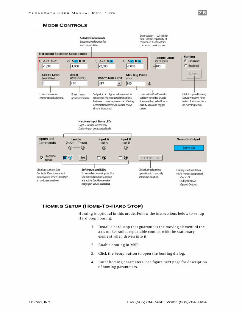
MODE CONTROLS
Enter maximum motor speed allowed.
Enter motor acceleration rate.
Click during homing operation to manually set home position.
Displays output status.HLFB modes supported: >Servo On >AllSystemsGo >Speed Output
Check to turn on Soft Controls. Override cannot be activated when ClearPath is hardware enabled.
Enter value (1-100) to limit peak torque capability of motor as a % of motor’s maximum peak torque.
Set Move IncrementsEnter move distance for each input state.
Set jerk limit. Higher values result in smoother, more gradual transitions between move segments of differing acceleration; however, overall move time is increased.
Click to open Homing Setup window. Refer to text for instructions on homing setup.
Soft Inputs and LEDs Emulate hardware inputs. For use only when Soft Controls are active. Caution: motor may spin when enabled.
Hardware Input Status LEDsLight = Input asserted (on)Dark = Input de-asserted (off)
Enter value (1-400mS) to set how long the Enable line must be pulled low to qualify as a valid trigger pulse.
HOMING SETUP (HOME-TO-HARD STOP) Homing is optional in this mode. Follow the instructions below to set up Hard Stop homing.
1. Install a hard stop that guarantees the moving element of the axis makes solid, repeatable contact with the stationary element when driven into it.
2. Enable homing in MSP.
3. Click the Setup button to open the homing dialog.
4. Enter homing parameters. See figure next page for description of homing parameters.

C L E A R P A T H U S E R M A N U A L R E V . 1 . 8 9 77
TEKNIC, INC. FAX (585)784-7460 VOICE (585)784-7454
Homing setup dialog
5. Test and modify your homing setup for consistent, repeatable
performance.

C L E A R P A T H U S E R M A N U A L R E V . 1 . 8 9 78
TEKNIC, INC. FAX (585)784-7460 VOICE (585)784-7454
PULSE BURST POSITIONING.
MODE SUMMARY ClearPath will move a distance proportional to the number of pulses sent to Input B. This mode offers much of the flexibility of a “step-and-direction” system, without the need for an expensive indexer to create smooth move trajectories; that function is handled by ClearPath’s internal trajectory generator. This mode is limited to two speeds and one acceleration/deceleration rate of the user’s choice.
Note: A fairly simple PLC counter or a software loop can be used to generate pulses for use with this mode.
HOW IT WORKS Assert the Enable Input to energize the motor. (Note: ClearPath can be configured to perform a homing routine upon enable.) To execute positioning moves, send a high speed stream of pulses to Input B, where each pulse represents a small, incremental unit of distance. Total move distance is determined by total number of pulses sent to Input B.
All moves are executed at the user-defined acceleration and speed setting. Direction of motor shaft rotation is controlled by Input A. See inputs and timing diagram below.
Trigger function: Alternate Speed
Briefly pulse the Enable input low, and the next pulse burst sent to ClearPath will result in a move at the alternate speed setting. Once that move is complete, ClearPath automatically returns to its default speed setting.
Signal Function Input Type
Input A
Motor velocity vs. time
Input B
Enable
Direction Select
Pulse Input
EnableSpeed Select Pulse low to select alternate speedTrigger
Logic: High=CW Low=CCW
Pulse: High-Speed Pulse Burst
Logic: High=Enable Low=Disable
0
1
0
1
t
v
Example Timing
Notes: Maximum pulse input frequency = 500 kHz. Minimum pulse on/off time = 1uS.
0
1
Trigger pulse
Pulse Burst PositioningPulse Positioning
alternate speed
Pulse Burst Positioning Mode: Inputs and Timing Diagram
Notes:
• The frequency of the pulse train applied to Input B must always be higher than the specified speed limit(s). This ensures that the motor is never “consuming” pulses faster than they are being

C L E A R P A T H U S E R M A N U A L R E V . 1 . 8 9 79
TEKNIC, INC. FAX (585)784-7460 VOICE (585)784-7454
supplied. See the “Burst Frequency Spec” (circled in red on the figure below) for the range of allowable pulse input frequencies.
• The pulse train can be of constant frequency, i.e. there is no need to ramp pulse frequency up or down as in a “step-and-direction” system. ClearPath automatically manages acceleration and deceleration profiles with its internal trajectory generator.
MODE CONTROLS
Displays allowable range of input pulse frequencies (based on Input Resolution and Speed Limit settings).
Click during homing operation to manually set home position.
Enter primary motor speed.
Enter alternate motor speed.
Enter motor acceleration.
Displays output status.HLFB modes supported: >Servo On >AllSystemsGo >Speed Output
Check to turn on Soft Controls. Override cannot be activated when ClearPath is hardware enabled.
Enter value (1-100) to limit peak torque capability of motor as a % of motor’s maximum peak torque.
Select number of input pulses required to rotate the motor shaft exactly one revolution.
Set jerk limit. Higher values result in smoother, more gradual transitions between move segments of differing acceleration; however, overall move time is increased.
Click to open Homing Setup window (when homing is enabled).
Soft Inputs and LEDs Emulate hardware inputs. For use only when Soft Controls are active. Caution: motor may spin when enabled.
Hardware Input Status LEDsLight = Input asserted (on)Dark = Input de-asserted (off)
Enter value (1-400mS) to set min time the Enable line must be pulsed low to select the alternate speed.
Check to reverse direction of motor shaft rotation.
HOMING SETUP (HARD STOP HOMING) In this mode, ClearPath can be configured to home to a hard stop to establish a home reference position before functional positioning begins.
1. Install a hard stop that guarantees the moving element of the axis makes solid, repeatable contact with the stationary element when driven into it.
2. Enable homing in MSP.

C L E A R P A T H U S E R M A N U A L R E V . 1 . 8 9 80
TEKNIC, INC. FAX (585)784-7460 VOICE (585)784-7454
3. Click the Setup button to open the homing dialog.
4. Enter homing parameters. See figure below for description of homing parameters.
Homing setup dialog
5. Test and modify your homing setup for consistent, repeatable performance.

C L E A R P A T H U S E R M A N U A L R E V . 1 . 8 9 81
TEKNIC, INC. FAX (585)784-7460 VOICE (585)784-7454
CLEARPATH SD (STEP AND DIRECTION) . The ClearPath SD family was designed to replace stepper motor/drive combos with a single, cost-effective unit. While all ClearPath SD models function in essentially the same way, there are differences in resolution and power between models within the family. See the Teknic/ClearPath website for complete information on SD Family ClearPaths.
STEP AND DIRECTION INPUT
MODE SUMMARY You provide standard step and direction signals and ClearPath faithfully follows them. Use the included RAS (Regressive Auto Spline) feature to smooth the motion profile. This mode is great for replacing stepper motor and drive systems with one compact device that costs less and does more.
HOW IT WORKS Assert the Enable Input to energize the motor. Then, supply standard step and direction pulses to Inputs A and B to command motion. This model requires step and direction signals from an external indexer, controller, or similar.
Signal Function Input Type
Input A
Motor velocity vs. time
Input B
Enable
Direction
Step
Enable
NA NATrigger
Logic: High=CW Low=CCW
Pulse: Digital Step Input
Logic: High=Enable Low=Disable
0
1
0
1
t
v
Example Timing
Notes: Maximum pulse input frequency = 500 kHz. Minimum pulse on/off time = 1uS.
0
1
0
1
Step and Direction Input ControlStepper Replacement
Step and Direction Inputs and Timing
Notes:
• Maximum pulse input frequency = 500 kHz.
• Minimum pulse on/off time = 1uS. See diagram next page for step and direction timing information.
• Motion occurs on the rising edge of each step input pulse.
• Time before Disable = 10 mS

C L E A R P A T H U S E R M A N U A L R E V . 1 . 8 9 82
TEKNIC, INC. FAX (585)784-7460 VOICE (585)784-7454
STEP AND DIRECTION TIMING The ClearPath Step Input is “positive edge-triggered”, so ClearPath registers a step only when Input B sees the rising edge of a step input pulse (i.e. an electrical transition from low to high). Refer to the diagram below for details and important step and direction signal timing requirements.
ClearPath can be configured to move one count for each step received, or one count per [x steps] received (based on the Input Resolution setting).
Step
Position
Direction
n n-1 n+1n
tcyc
tpw
tdstds
tdh
tds Minimum time between direction change and step input change = 25nS
tcyc Minimum step cycle time = 2uS
tpw Minimum step pulse width = 1 uS
tdh Minimum direction hold time = 1uS
Steps register onrising edges only
Note: In this example, 1 step at Input B = 1 count of shaft motion. This ratio can be changed using Input Resolution setting.
Input B
Input A
ClearPath minimum step and direction input timing diagram

C L E A R P A T H U S E R M A N U A L R E V . 1 . 8 9 83
TEKNIC, INC. FAX (585)784-7460 VOICE (585)784-7454
MODE CONTROLS
Enter motor velocity. For use with Soft Controls.
Enter motor acceleration. For use with Soft Controls.
Displays output status.HLFB modes supported: >Servo On >AllSystemsGo >InRange
Check to turn on Soft Controls. Override cannot be activated when ClearPath is hardware enabled.
Select number of input pulses required to rotate the motor shaft exactly one revolution.
Enter value (1-100) to limit peak torque capability of motor as a % of motor’s maximum peak torque.
Set jerk limit. Higher values result in smoother, more gradual transitions between move segments of differing acceleration; however, overall move time is increased.
Click to open Homing Setup window (when homing is enabled).
Soft Inputs and LEDs Emulate hardware inputs. For use only when Soft Controls are active. Caution: motor may spin when enabled.
Hardware Input Status LEDsLight = Input asserted (on)Dark = Input de-asserted (off)
Check to reverse direction of motor shaft rotation.

C L E A R P A T H U S E R M A N U A L R E V . 1 . 8 9 84
TEKNIC, INC. FAX (585)784-7460 VOICE (585)784-7454
HOMING SETUP (HARD STOP HOMING) In this mode, ClearPath can be configured to home to a hard stop to establish a home reference position before functional positioning begins.
1. Install a hard stop that guarantees the moving element of the axis makes solid, repeatable contact with the stationary element when driven into it.
2. Enable homing in MSP.
3. Click the Setup button to open the homing dialog.
4. Enter homing parameters. See figure next page for description of homing parameters.
Homing Setup dialog
5. Test and modify your homing setup for consistent, repeatable
performance.