Spicer PRO SHIFT 18 Speed Service Manual
48
18 Speed TRANSMISSION Service Manual MODELS: PSDO165–18 PSDO185–18 PSDO205–18 Bulletin No. SPSDO165-18 April 2004
-
Upload
angel-frausto-beltran -
Category
Documents
-
view
144 -
download
13
description
MANUAL DE SERVICIO TRANSMISION PRO SHIFT 18 SPICER
Transcript of Spicer PRO SHIFT 18 Speed Service Manual

18 SpeedTRANSMISSION
Service Manual
MODELS: PSDO165–18
PSDO185–18PSDO205–18
Bulletin No. SPSDO165-18 April 2004

2
PRO-SHIFT-18-Speed Transmission
Section I General InformationSpecifications ....................................................................................................................................................3
Torque Specifications ........................................................................................................................................4
Driver Instructions .............................................................................................................................................5
Section II MaintenanceAir Line Piping Diagram ...........................................................................................................................................7
Filter Regulator ....................................................................................................................................................... 8
Lubrication ...............................................................................................................................................................9
Section III General Disassembly ................................................................................................. 10
Section IV Shift Lever Disassembly ............................................................................................ 12
Section V Electrical Harness ....................................................................................................... 13
Section VI Range Case DisassemblyCase Exploded Drawing ........................................................................................................................................ 14
Gears Exploded Drawing .......................................................................................................................................15
Disassembly .......................................................................................................................................................... 17
Section VII Main Case DisassemblyMain Case Exploded Drawing ............................................................................................................................... 22
Clutch Housing Exploded Drawing ........................................................................................................................23
Main Case Gears Exploded Drawing .....................................................................................................................24
Disassembly .......................................................................................................................................................... 27
Section VIII Countershaft Disassembly & Reassembly............................................................. 31
Section IX Cleaning & Inspection Procedures ............................................................................................................. 32
Section X Main Case Reassembly ............................................................................................................................... 33
Section XI Range Case Reassembly ...........................................................................................................................37
Section XII Shift Lever Reassembly .............................................................................................................................41
Section XIII Troubleshooting ........................................................................................................................................ 42
TABLE OF CONTENTS

3
SAFETY FIRSTCarefully read this service manual beforebeginning any work on your Spicertransmission.
Throughout this literature, you will see symbols thatwarn of potential physical danger or product damage ifthe accompanying instructions aren’t followed. Hereare the symbols and their meanings.
This symbol indicates a potentially hazard-ous situation. If the instructions aren’tfollowed, the result could be death or seriousinjury.
This symbol indicates that you must dosomething in order for the transmission tofunction properly. For example, you must useonly one gasket underneath the shift tower. Ifit is eliminated, or more than one gasket isused, binding can occur. This would preventproper shifting of the transmission and coulddamage the unit.
This symbol indicates that you must NOT dosomething in order to avoid damaging thetransmission. For example, you must not usesealant underneath the shift tower. Usingsealant underneath the tower will preventproper interlock functioning and could
damage the unit.
Be sure you understand all procedures and instruc-tions in this manual before you begin working on yourSpicer Transmission. If you have any questions,contact your Spicer Transmission representative.
General Safety Precautions
Use a hoist whenever lifting thetransmission or shaft assemblies. Usinga hoist can help prevent muscle strain orother possible injuries.
Always wear safety glasses whenworking on the transmissions to helpprevent possible eye injury due to smallparts (such as snap rings) or metalchips that may fly up unexpectedlyduring a tear down or rebuild.
Be careful when picking up gears orother sharp components. If you aren’tcareful, you could cut your hands. Considerwearing heavy cloth gloves or coveringsharp objects with shop towels beforepicking them up.
When draining the transmission prior toworking on it, be careful to let the unitcool down first. Otherwise, hot transmis-sion fluid could cause burns.
!!!!!
!!!!!
!!!!!
!!!!!
!!!!!
!!!!!
The information in this service manual was current at the time of publication.This information is subject to change at any time without notice.
4
GENERALINFORMATION SECTION I
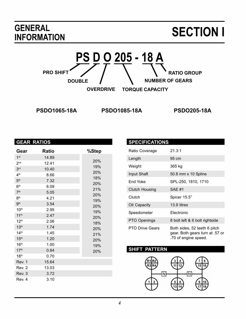
PS D O 205 - 18 APRO SHIFT
DOUBLEOVERDRIVE TORQUE CAPACITY
NUMBER OF GEARSRATIO GROUP
PSDO1065-18A PSDO1085-18A PSDO205-18A
GEAR RATIOS
Gear Ratio %Step1st 14.892nd 12.413rd 10.404th 8.665th 7.326th 6.097th 5.058th 4.219th 3.5410th 2.9511th 2.4712th 2.0613th 1.7414th 1.4515th 1.2016th 1.0017th 0.8418th 0.70Rev. 1 15.64Rev. 2 13.03Rev. 3 3.72Rev. 4 3.10
20%19%20%18%20%21%20%19%20%19%20%18%20%21%20%19%20%
SPECIFICATIONSRatio Coverage 21.3:1
Length 95 cm
Weight 365 kg
Input Shaft 50.8 mm x 10 Spline
End Yoke SPL-250, 1810, 1710
Clutch Housing SAE #1
Clutch Spicer 15.5”
Oil Capacity 13.9 litres
Speedometer Electronic
PTO Openings 8 bolt left & 6 bolt rightside
PTO Drive Gears Both sides, 52 teeth 6 pitchgear. Both gears turn at .57 or.70 of engine speed.
SHIFT PATTERN
R1 R2R3 R4
3 411 12
7 815 16
1 2 5 613 14
9 1017 18
5
GENERALINFORMATION SECTION I
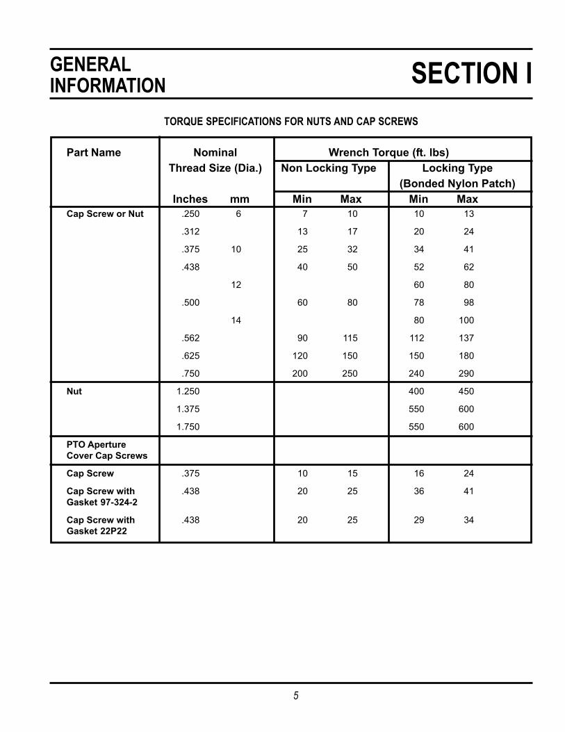
TORQUE SPECIFICATIONS FOR NUTS AND CAP SCREWS
Part Name Nominal Wrench Torque (ft. lbs)Thread Size (Dia.) Non Locking Type Locking Type
(Bonded Nylon Patch)Inches mm Min Max Min Max
Cap Screw or Nut .250 6 7 10 10 13
.312 13 17 20 24
.375 10 25 32 34 41
.438 40 50 52 62
12 60 80
.500 60 80 78 98
14 80 100
.562 90 115 112 137
.625 120 150 150 180
.750 200 250 240 290
Nut 1.250 400 450
1.375 550 600
1.750 550 600
PTO ApertureCover Cap Screws
Cap Screw .375 10 15 16 24
Cap Screw with .438 20 25 36 41Gasket 97-324-2
Cap Screw with .438 20 25 29 34Gasket 22P22
6
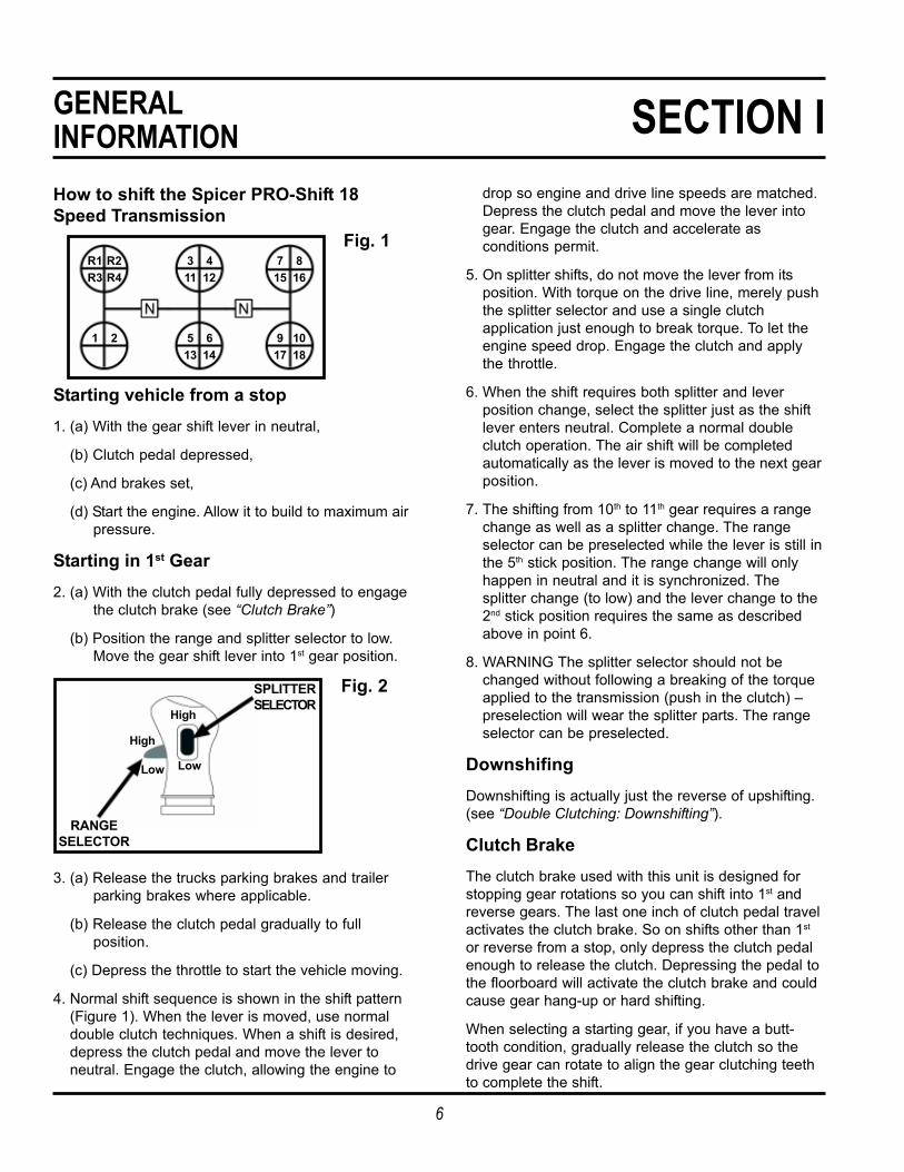
GENERALINFORMATION SECTION IHow to shift the Spicer PRO-Shift 18Speed Transmission
Fig. 1
Starting vehicle from a stop1. (a) With the gear shift lever in neutral,
(b) Clutch pedal depressed,
(c) And brakes set,
(d) Start the engine. Allow it to build to maximum airpressure.
Starting in 1st Gear2. (a) With the clutch pedal fully depressed to engage
the clutch brake (see “Clutch Brake”)
(b) Position the range and splitter selector to low.Move the gear shift lever into 1st gear position.
Fig. 2
3. (a) Release the trucks parking brakes and trailerparking brakes where applicable.
(b) Release the clutch pedal gradually to fullposition.
(c) Depress the throttle to start the vehicle moving.
4. Normal shift sequence is shown in the shift pattern(Figure 1). When the lever is moved, use normaldouble clutch techniques. When a shift is desired,depress the clutch pedal and move the lever toneutral. Engage the clutch, allowing the engine to
drop so engine and drive line speeds are matched.Depress the clutch pedal and move the lever intogear. Engage the clutch and accelerate asconditions permit.
5. On splitter shifts, do not move the lever from itsposition. With torque on the drive line, merely pushthe splitter selector and use a single clutchapplication just enough to break torque. To let theengine speed drop. Engage the clutch and applythe throttle.
6. When the shift requires both splitter and leverposition change, select the splitter just as the shiftlever enters neutral. Complete a normal doubleclutch operation. The air shift will be completedautomatically as the lever is moved to the next gearposition.
7. The shifting from 10th to 11th gear requires a rangechange as well as a splitter change. The rangeselector can be preselected while the lever is still inthe 5th stick position. The range change will onlyhappen in neutral and it is synchronized. Thesplitter change (to low) and the lever change to the2nd stick position requires the same as describedabove in point 6.
8. WARNING The splitter selector should not bechanged without following a breaking of the torqueapplied to the transmission (push in the clutch) –preselection will wear the splitter parts. The rangeselector can be preselected.
DownshifingDownshifting is actually just the reverse of upshifting.(see “Double Clutching: Downshifting”).
Clutch BrakeThe clutch brake used with this unit is designed forstopping gear rotations so you can shift into 1st andreverse gears. The last one inch of clutch pedal travelactivates the clutch brake. So on shifts other than 1st
or reverse from a stop, only depress the clutch pedalenough to release the clutch. Depressing the pedal tothe floorboard will activate the clutch brake and couldcause gear hang-up or hard shifting.
When selecting a starting gear, if you have a butt-tooth condition, gradually release the clutch so thedrive gear can rotate to align the gear clutching teethto complete the shift.
SPLITTERSELECTOR
RANGESELECTOR
High
Low
High
Low
R1 R2R3 R4
3 411 12
7 815 16
1 2 5 613 14
9 1017 18

7
GENERALINFORMATION SECTION IDouble ClutchingUpshifting: The normal double clutching technique issuggested. When you want to shift, depress the clutchand move the lever to neutral. Engage the clutch andallow the engine RPM to drop so engine speed anddrive line speed match. Depress the clutch and movethe lever into gear. Engage the clutch and accelerateas conditions permit.
Downshifting: Downshifting is the reverse of upshift-ing. As the engine approaches the shift point (start thedownshift approximately 50-100 RPM above the shiftpoint), depress the clutch and move the lever toneutral. Engage the clutch and raise the engine RPMuntil the engine and drive line speeds are equal(normally, governed speed). Depress the clutch, thenshift into the next low gear. Engage the clutch.
Skip ShiftingExperienced drivers sometimes want to skip some ofthe ratios. This is acceptable. However, you should dothis only when operating conditions allow. Your speed,the load, and the road type and condition should beconsidered.
RemindersDouble clutch when shifting. This will helpcomponents match speed better during shiftsand will help ensure proper engagement.
Downshift through all gear speeds when youare slowing down. Chassis and trailer brakelife can be increased by doing this.
Do not force the shift since this can causedamage to clutch collars and clutching teeth.Use steady force on the shift lever to completeshifts.
Do not coast in neutral. The vehicle could loseRPMs during coasting and you may not be ableto shift back into the proper gear.
Do not downshift at road speeds that are toofast. This could prevent proper gear engage-ment and could damage clutching teeth.
Do not tow vehicles without first pulling theaxles or disconnecting the driveshaft. If youtow the vehicle without doing this, you candamage drive train components because thesystem lubrication is inadequate when thevehicle is towed.
!!!!!
!!!!!

8
MAINTENANCE SECTION IIAIR LINE PIPING DIAGRAM

9
Filter RegulatorThe 18 speed uses a filter regulator preset at 50-55lbs.
Use only petroleum-based solvents toclean parts. Other types of solvents coulddamage filter components and affect properoperation.
Blow air through the filter (inside andoutside) to dislodge surface contami-nants. Otherwise, these contaminants couldaffect proper filter operation and lead toequipment damage.
Do not disassemble the regulator section(9): It is not field-repairable.
If it is damaged, replace it.
1. Clean or replace the filter element (7) every 6-12months, or whenever slow shifting is encountered.The element should be replaced after threecleanings. If regulator malfunction is indicated,replace the entire unit.
2. To service the filter section, shut off the airpressure. Unscrew the bowl (1) and remove theO-ring (2). Unscrew the stud (4). Remove thelouver (5), upper gasket (6), element (7), andlower gasket (8) from the stud. Do notdisassemble the regulator section (9).
3. After cleaning, inspect the parts carefully. Replaceany damaged parts.
4. Reassemble the unit by first installing the element(7) on the stud (4), so that the large end of theinternal taper (thinnest wall section) is toward thehax on the stud. Torque the stud to 5-10 lbs. inch.
5. Apply a wipe coat of Dow Corning DC7 SiliconeGrease (or equivalent) to the O-ring (2) seatingsurfaces on the regulator (9) and bowl (1). Apply alight, even coat of Molykote “G” (or equivalent) tothe bowl threads. Torque the bowl to 5-10 lbs.inch. If the drain valve (3) was removed, reinstall itand torque it to 10-15 lbs. inch.
!!!!!
!!!!!
MAINTENANCE SECTION II

10
MAINTENANCE SECTION IILubrication
CAUTION: To ensure proper lubrication andoperating temperatures in this unit, the properlubricants must be used. Correct oil levels
must be maintained. Spicer recommends using onlylubricants produced by reputable, well-known suppli-ers. If you want to use a lubricant not specified below,please contact your local truck dealer to determinewhether the lubricant is suitable for your purposes.
Recommended LubricantsThe lubricants listed below are recommended for usein all Spicer mechanical transmissions.
Type Viscosity
HEAVY DUTY MOTOR OIL SAE 50According to specificationsMIL-2104D orMIL-I-46152B, API SF/CD(MIL-2104B and C or 46152are also acceptable)
SYNTHETIC MOTOR OIL CD SAE 50According to specificationsMIL-L-2104D orMIL-46152B, API-SF/CD
PURE MINERAL OILS FOR SAE 90GEAR TYPES R and OContains corrosion andoxidation inhibitorsAPI-GLI
Oil ChangesDepending on the oil used and the vehicle applicationmany factors will influence oil change periods. Pleasecontact your lubricant supplier for the replacementintervals or contact your local Spicer agent.
RefillingFirst remove all dirt around the filler plug. Then refillthe transmission with new oil. Use the grade recom-mended for the existing season and prevailing ser-vice. The lubricant should be level with the oil fill pluglocated on the right side of the transmission case.
OverfillingCAUTION: Do not overfill the transmission.This usually results in oil breakdown due toexcessive heat and aeration from the churning
action of the gears. Early breakdown of the oil willresult in heavy varnish and sludge deposits that plugup oil ports and build up on splines and bearings.
!!!!!

11
GENERALDISASSEMBLY SECTION IIIImportant ProcedureTo locate and correct transmission troubles, asystematic procedure should be followed.
Road test whenever possible. Mechanics usually getseconded or third-hand reports of trouble experiencedwith the unit. These reports do not always accuratelydescribe the actual conditions. Sometimes symptomsseem to indicate trouble in the transmission, whileactually the problem is the axle, driveshaft, universaljoints, engine or clutch. This is especially true of noisecomplaints. Therefore, before removing the transmis-sion or related components to locate trouble, road testto check the possibility of trouble in other closelyassociated units. Road testing is most effective whenthe mechanic drives the vehicle. However, riding withthe driver can be informative.
Check Functioning Prior to DisassemblyIf a remote control is used, a careful check of theremote and connecting linkages (and their adjustment)must be made. The remote unit must be in goodworking order if the transmission is expected to shiftsatisfactorily.
Many times, the answer to the trouble is apparentwhen the unit is inspected prior to disassembly. Butthis evidence is often lost when the parts are sepa-rated. If possible, check the unit prior to disassembly.Bear in mind that a careful inspection of the unitshould be made as each disassembly step is per-formed.
Inspect Thoroughly During DisassemblyIt is poor practice to disassemble a unit or the com-plete transmission as quickly as possible withoutexamining the parts. The mechanic may completelydisassemble a unit and fail to find the cause of thetrouble, unless he examines the parts. After thetransmission is disassembled, check the lubricant forforeign particles. This is a source of trouble oftenoverlooked during the disassembly.
Repair or Replace Worn PartsMany times the parts or critical adjustments causingthe trouble are not replaced or corrected because themechanic only inspects and replaces parts that havefailed completely. All pieces should be carefullyexamined because broken parts are often just theresult – not the cause – of the problem. All parts thatare broken or worn and no longer meet specificationsshould be replaced.
Also, parts that are worn to the extent that they do nothave a long service life remaining should be replaced.Replacing these parts now will avoid another teardown on the unit in the near future. Also at this time,make the recommended changes or modifications tobring the transmission up to date and increase theservice life of the unit.

12
GENERALDISASSEMBLY SECTION III
Read this section before starting thedetailed disassembly procedures.
Follow procedures closely to ensureproper transmission operation.
Rebuild FacilitiesA suitable holding fixture or overhaul stand with a holefor the input shaft is desirable.
For easier working conditions, table height should be28-30 inches. A light chain hoist should be used tohandle the mainshaft and counter shafts duringremoval and reassembly procedures.
CleanlinessTransmissions should be steam cleaned prior todisassembly. Seal all openings before steam cleaningto prevent entry of dirt and water, which can damageserviceable parts.
Dirt is abrasive and will cause premature wear ofbearings and other parts. Spicer suggests that me-chanics have a wash tank available to clean parts justprior to reassembly.
BearingsWhen a transmission is removed at relatively lowmileage, bearings should be removed with pullersdesigned for this purpose. Wrap the bearings to keepout dirt. Clean, inspect, and lubricate all bearings justprior to reassembly. If accumulated mileage is over150,000 miles, we suggest that all bearings bereplaced. If bearings are worn or damaged, alwaysreplace them regardless of mileage.
End Yokes and FlangesDo not hammer on end yokes and flanges toremove or install them. It is not only destructiveto the yoke or the flange itself, but can also
cause serious internal transmission damage. Ham-mering destroys or mutilates the pilot diameters andwarps or bends the flange. Hammering on end yokeswill close-in the bearing bores or misalign yoke lugs.This will result in early failures of journal needlebearings.
Serious damage can be done internally to bearings,thrust faces and washers by hammering on externalparts. In most designs, when the yoke/flange lock nutsare tightened and secure, the internal bearings andgears are in proper location. When the yoke/flange isdriven on the shaft, however, two conditions can exist.
(a) If the bearing fit is tight on the shaft, usually thebearings will brinell as they must absorb thepounding force.
(b) If the bearing fit is loose, the shaft will keepmoving inward until it is stopped by the internalparts.
These conditions must be prevented.
Power Take-OffsRefer to your owner’s manual, installation procedures,and safety precautions when installing any PTO onyour transmission.
Front Bearing RetainerWhen installing the front bearing retainerand seal in the transmission, use the red
plastic sleeve to prevent serious damage to theoil seal. Failure to use the seal sleeve will void thewarranty.
!!!!!
!!!!!
Push sleeve over end of shaftInstall bearing cap assemblyafter red sleeve is in placeInstall seal dry
Hydrodynamic lipSeal must be installed so thatHydrodynamic lip faces towardinside of transmission
Remove seal cardboard shipping tube or plastic installation sleevejust prior to installing bearing cap assembly to transmission

13
SHIFT LEVERDISASSEMBLY SECTION IVShift Lever Disassembly1. Cut the tie-down straps and lift the boot off the
lever.
2. Holding the lever in a vise, remove the tower snapring.
3. Pull the lever, the upper and lower plastic socketsand the two opposing springs from the tower.
Shift Pattern Insert
Nut
Washer
Shift Knob
Castellated Nut
Upper Lever
Pin
Upper Lever
Isolator Assembly
Snap Ring
UpperSocket
Lower Lever
LowerSocket
Opposing DiskSprings
Tower
Gasket
Bolt
Breather
Washer

14
ELECTRICALHARNESS SECTION V

15
RANGE CASEDISASSEMBLY SECTION VI
SPLITTER PISTON HOUSING
NUT
SPLITTER PISTONO`RINGS
BOLT
BEARING CAP
FITTING
SWITCH (3)
REAR CASE
BOLT
SPLITTER ROD
BOLT
SPLITTER FORKRANGE FORK
RANGE ROD
BOLT
FILTER REGULATOR
CLAMP
BEARING CAPFITTING
PLUG
O`RINGS
BOLT
BRACKET
NUT
OUTPUT BEARINGCAP REAR SEAL
RANGE PISTON
RANGE PISTONHOUSING
FITTING
SPLITTER PISTON HOUSING
NUT
SPLITTER PISTONO`RINGS
BOLT
BEARING CAP
FITTING
SWITCH (3)
REAR CASE
BOLT
SPLITTER ROD
BOLT
SPLITTER FORKRANGE FORK
RANGE ROD
BOLT
FILTER REGULATOR
CLAMP
BEARING CAPFITTING
PLUG
O`RINGS
BOLT
BRACKET
NUT
OUTPUT BEARINGCAP REAR SEAL
RANGE PISTON
RANGE PISTONHOUSING
FITTING

16
RANGE CASEDISASSEMBLY SECTION VI
CLUTCH DRIVE GEAR
WASHER
SYNCHRONIZER CONE
HIGH RANGE DRIVE GEAR
MAIN SHAFT
BOLT
CONE
CUP
CONE
THRUST WASHER
BEARING
LOW RANGE GEAR
OUTPUT SHAFT
CLUTCH DRIVE GEAR
WASHER
SYNCHRONIZER CONE
HIGH RANGE DRIVE GEAR
MAIN SHAFT
BOLT
CONE
CUP
CONE
THRUST WASHER
BEARING
LOW RANGE GEAR
OUTPUT SHAFT

17
RANGE CASEDISASSEMBLY SECTION VI
CUP
CONE
RANGE COUNTERSHAFT
CONE
CUP
SPRING
RANGE SYNCHRONIZER
RANGE SYNCHRONIZER
RANGE SYNCHRONIZER
CUP
CONE
RANGE COUNTERSHAFT
CONE
CUP
SPRING
RANGE SYNCHRONIZER
RANGE SYNCHRONIZER
RANGE SYNCHRONIZER

18
RANGE CASEDISASSEMBLY SECTION VI
1.Remove wiring harness from gear position switches
2.Remove wiring harness from shift solenoids
3.Remove all air lines and necessary fittings(note: it is not necessary to mark lines for reassembly since a schematic is provided on page 7)
4.Remove three gear position switches and back-up lightswitch
5.Remove detent balls and springs
6.Remove interlock retaining bolts, plate and interlock

19
RANGE CASEDISASSEMBLY SECTION VI
7.Remove the overdrive shift fork reversing mechanism
8.Remove two clutch housing bolts from the inside of thebell housing before placing the transmission on end
9.Using a chain hoist, carefully place thetransmission on a workbench that has ahole to accommodate the input shaft
10.Remove the rear bearing retainer and speedometergear
!!!!!

20
12.Remove the rear countershaft bearing retainer shims
13.Remove the range and splitter piston housings
14.Remove the range and splitter piston retaining nutsand pistons
15.Remove all the range case bolts, then thread two ofthe case bolts into the threaded holes provide and drawtight to split the range case from the main case
16.Using a chain hoist, lift the range case fromthe unit
11.Remove air filter regulator, bracket, range and splittervalves
RANGE CASEDISASSEMBLY SECTION VI
!!!!!

21
17.Remove range fork and synchronizer
RANGE CASEDISASSEMBLY SECTION VI
19.Using a puller, remove the high-range gear andsynchronizer
18.Use an 1 ½” socket to remove the synchronizer ring
20.Remove range countershafts
21.Using a plastic mallet, remove output shaft fromrange case assembly REPLACE HAMMER
22.Using a press, remove inner output bearing and lowrange gear from output shaft

22
23.Remove rear countershaft bearing retainers
24.Remove rear main shaft bearing retainers
RANGE CASEDISASSEMBLY SECTION VI

23
MAIN CASEDISASSEMBLY SECTION VII
PLUG SPRING BALLBOLT
BEARING CUP
BEARING CUP
BEARING CUP
BOLT
BOLT
DOWELL PIN
FILL PLUG
PLUG
COVER PTO 8
BOLTMAGNET
MAIN CASE
BOLT
COVER PTO8
PIVOT PLATE
PIVOT PIN
PIVOT BEARING
ROLL PIN
PIVOT COVER
PLUG
FILL PLUG
PLUNGER
SPRING
STUD
WASHER
NUT PLUG SPRING BALLBOLT
BEARING CUP
BEARING CUP
BEARING CUP
BOLT
BOLT
DOWELL PIN
FILL PLUG
PLUG
COVER PTO 8
BOLTMAGNET
MAIN CASE
BOLT
COVER PTO8
PIVOT PLATE
PIVOT PIN
PIVOT BEARING
ROLL PIN
PIVOT COVER
PLUG
FILL PLUG
PLUNGER
SPRING
STUD
WASHER
NUT

24
MAIN CASEDISASSEMBLY SECTION VII
CLUTCH HOUSING
BUSHING
O`RING
CUP
DISCHARGE TUBE
ROLL PIN
BOLT
GEAR PUMP
SHAFT
BOLT
PICK UP TUBE
SNAP RING
PUMP GEARPUMP BODY
BOLT
CERAMIC MAGNET
PUMP BASEROLL PIN
FITTING
CUP
O`RING
DOWEL PIN
DOWL
PIVOT COVER
CLUTCH HOUSING
BUSHING
O`RING
CUP
DISCHARGE TUBE
ROLL PIN
BOLT
GEAR PUMP
SHAFT
BOLT
PICK UP TUBE
SNAP RING
PUMP GEARPUMP BODY
BOLT
CERAMIC MAGNET
PUMP BASEROLL PIN
FITTING
CUP
O`RING
DOWEL PIN
DOWL
PIVOT COVER
BUSHING
CLUTCH HOUSING
BOLTS
SEALSHAFT
FORK
BOLT
BOLT
SHAFT
CLUTCH BRAKE
SEALRETAINER INSPECTION COVER
BOLT
WASHER
FITTING
BUSHING
CLUTCH HOUSING
BOLTS
SEALSHAFT
FORK
BOLT
BOLT
SHAFT
CLUTCH BRAKE
SEALRETAINER INSPECTION COVER
BOLT
WASHER
FITTING

25
MAIN CASEDISASSEMBLY SECTION VII
SHIMS
CUP
CONE
KEYSTHRUST RING
C/S 4TH GEAR
C/S DRIVE GEAR
CONECOUNTERSHAFT
THRUST RING
SPACER
THRUST RING
C/S 1ST GEARREV IDLER
C/S 2ND GEAR
BOLT
SPACER
SHAFT
BEARING
PTO GEAR
C/S 3RD GEAR
C/S 5TH GEAR
SHIMS
CUP
CONE
KEYSTHRUST RING
C/S 4TH GEAR
C/S DRIVE GEAR
CONECOUNTERSHAFT
THRUST RING
SPACER
THRUST RING
C/S 1ST GEARREV IDLER
C/S 2ND GEAR
BOLT
SPACER
SHAFT
BEARING
PTO GEAR
C/S 3RD GEAR
C/S 5TH GEAR

26
MAIN CASEDISASSEMBLY SECTION VII
SPIRAL RING
SPLITTER CLUTCH RING
DRIV E GEAR
INPUT SHAFT
SPLITTER HUB
SPLITTER COLLAR
MAIN SHAFT
3RD GEAR
5TH GEAR
BEARINGTHRUST WASHER
REVERSE GEAR
SHIFT COLLAR
4TH GEAR
SPLITTER CLUTCH RING
SPIRAL RING
SHIFT COLLAR
SHIFT COLLAR
1ST GEAR
2ND GEAR
SPIRAL RING
SPLITTER CLUTCH RING
DRIV E GEAR
INPUT SHAFT
SPLITTER HUB
SPLITTER COLLAR
MAIN SHAFT
3RD GEAR
5TH GEAR
BEARINGTHRUST WASHER
REVERSE GEAR
SHIFT COLLAR
4TH GEAR
SPLITTER CLUTCH RING
SPIRAL RING
SHIFT COLLAR
SHIFT COLLAR
1ST GEAR
2ND GEAR

27
MAIN CASEDISASSEMBLY SECTION X
SHIFT ROD 1/REV
GRUB SCREW
SHIFT FORK 1/REV
GRUB SCREW
BEARING
SHIFT FORK 4/5
SHIFT BRACKET 1/REV
BEARINGSHIFT ROD 2/3
SHIFT FORK 2/3GRUB SCREW
SHIFT BRACKET 4/5SHIFT ROD 4/5
GRUB SCREW
THRUST BRACKET 4/5GRUB SCREW
SHIFT ROD 1/REV
GRUB SCREW
SHIFT FORK 1/REV
GRUB SCREW
BEARING
SHIFT FORK 4/5
SHIFT BRACKET 1/REV
BEARINGSHIFT ROD 2/3
SHIFT FORK 2/3GRUB SCREW
SHIFT BRACKET 4/5SHIFT ROD 4/5
GRUB SCREW
THRUST BRACKET 4/5GRUB SCREW

28
MAIN CASEDISASSEMBLY SECTION VII
1.Remove bolts joining the main case to the clutchhousing. After removing all the bolts, thread two of thecase bolts into the threaded holes provided in the maincase and draw tight to split the main case from theclutch housing
2.Using a chain hoist, lift the main case from theclutch housing. (Be extremely careful not to catch thecase on the shift fork rods and the oil spry tube as you removethe main case)
3.Use a slide hammer with a 3/8" 16 thread adapter toremove the reverse idler shaft
4.Remove the reverse idler gear, caged needle bearingand spacer
!!!!!

29
MAIN CASEDISASSEMBLY SECTION VII
6.Remove shift fork and rail assembly
7.Place countershaft and mainshaft assemblyinto “countershaft/mainshaft” assembly fixture
8.Remove the lifting tool and slide the countershaftsapart
9.Remove tapered bearing, thrust washer and reversegear
5.Install an “A-frame lifting fixture” and use achain hoist to remove the shaft assembly!!!!!
!!!!!

30
SECTION VII
12.Remove 2nd gear, 2nd/3rd gear clutch collar and 3rd
gear
13.Remove 5th gear and 4th/5th clutch collar and 4th gear
14.Remove splitter clutch gear and shift collar
15.Remove 3 retaining bolts from OPTI-LUBE pump
11.Remove 1st gear and 1st/ reverse clutch collar
10.Remove mainshaft
MAIN CASEDISASSEMBLY

31
MAIN CASEDISASSEMBLY SECTION VII
16.Remove OPTI-LUBE distribution tube
17.To remove the input shaft and bearing cap, removethe four cap retaining bolts. Pull the shaft from thehousing. It may be helpful to place 2 bolts in thethreaded bearing cap holes. Tightening the bolts willdraw the bearing cap from the housing. Tap the inputshaft out of the bearing cap. To disassemble the inputshaft assembly, remove the snap ring, press the bear-ing off the shaft

32
COUNTERSHAFTDISASSEMBLY & REASSEMBLY SECTION VIII
2.If a straight edge is placed between the teeth(painted here to show the timing marks) every gear onthe countershaft will be in line
1.This view of the countershaft shows the direction ofthe gears. The gears are secured with three keys, withthe exception of reverse. This gear is part of the shaft,All gears can be pressed off one at a time towards thefront of the countershaft

33
CLEANING & INSPECTIONPROCEDURES SECTION IXCleaningPrior to reassembly, wash all parts thoroughly.
Use a petroleum-based solvent. Refer tothe solvent manufacturer’s saftey precautionsto prevent personal injury or transmissiondamage.
Do not use water or steam to cleaninternal components. If you do, it couldcause corrosion of these components.
Do not use gasoline to clean parts. Gasolinecan explode, causing serious physical injury.
Dry the parts immediately with compressed air. Coatthem with lubricant if they are to be reassembledimmediately. If the parts are to be stored, coat themwith a rust inhibitor and wrap them to keepcontamination out.
Inspect parts thoroughly for wear or damage. Partsdamaged or worn from previous service must bereplaced to insure maximum rebuild life. Suggestedinspection procedures include the following.
Inspection
Clutch CollarsBoth the internal and external teeth must have sharpedges. Check for chipped or broken teeth, or teethwith rounded corners. Also, examine fork slots forwear. Replace collars if any of these conditions exist.
GearsExamine for broken or cracked operating and clutch-ing teeth. Also, check for any unusual wear patterns. Ifany of the preceding exists, replace the gear. If a gearis replaced, also replace the mating gear.
Thrust WashersCheck for flatness or excessive face wear, cracks,scoring, or signs of heat damage. Replace if any ofthese conditions exists.
Snap RingsNew snap rings are recommended with every rebuild.
MainshaftCheck for signs of twisting or misalignment. Also,check for worn or damaged splines. Replace the shaftif any of these conditions exists.
Remote ControlCheck the shift fingers, bushing bores and rods forexcessive wear or scuffing. Replace springs, bearingraces, boots and seals. Clean all reusable partsthoroughly and apply a light coat of grease to the pivotpoints when reassembling.
BearingsNew bearings are recommended with every rebuild.(See “General Disassembly-Bearings” for furtherinformation)
HousingsInspect the housing sections for cracks. If cracks exist,replace that section of the housing. Also, inspect theshift bar support bracket for cracks or worn slots.Replace if either of these conditions exists.
!!!!!
!!!!!

34
MAIN CASEREASSEMBLY SECTION X
1.Install the input shaft
2.Apply Loctite 515 to front bearing retainer and install.Torque bolts to 38 – 42 ft. lbs.
3.Install OPTI-LUBE spray distribution tube and torquebolts to 38 – 42 ft.lbs.
4.Install OPTI-LUBE pump with 3 bolts and torque to 38– 42 ft.lbs.
5.Install countershafts, splitter clutch gear and shiftcollar into “countershaft / mainshaft” assembly fixture.Continue building mainshaft assembly by placing 5th
gear and 4th / 5th clutch collar and 4th gear into fixture

35
6.Install 2nd gear, 2nd / 3rd gear clutch collar and 3rd gear
7.Install 1st gear and 1st / reverse clutch collar
8.Install mainshaft
9.Install tapered bearing, thrust washer and reversegear
10.Install shift fork and rail assembly
11.Install the reverse idler gear, caged needle bearingand spacer
MAIN CASEREASSEMBLY SECTION X

36
12.Attach the “A-Frame Lifting Fixture” and usea chain hoist to lower the gear assembly intothe clutch housing. (Be careful to line up the OPTI-LUBE pump drive gear)
13.Using a chain hoist, lower the main caseonto the clutch housing. (Be extremely careful not tocatch the case on the shift fork rods and the oil pray tube)
14.Install the case bolts and torque them to 78 – 98ft.lbs.
16.Install rear countershaft bearing retainers and torquebolts to 38 – 42 ft.lbs.
15.Install rear mainshaft bearing retainer and torquebolts to 38 – 42 ft.lbs.
MAIN CASEREASSEMBLY SECTION X
!!!!!
!!!!!

37
17.Measure front countershaft end play by prying thecountershaft up and down with a large screwdriver thruthe PTO opening. (End play should be .001 – .008)Adjust end play by adding, or subtracting shims underthe rear countershaft
MAIN CASEREASSEMBLY SECTION X

38
RANGE CASEREASSEMBLY SECTION XI
1.Install range countershafts and high range gearmaking sure to align the timing marks
2.Install high range synchronizer race, clutch gear,washer and bolt. Torque bolt to 380 – 400 ft. lbs.
6.Install range and splitter pistons and retaining nutsand torque to 29 – 45 ft.lbs.
5.Using a chain hoist lift the range case and attach tomain case with case bolts, torque to 38-42 ft. lbs.
3.Install cage needle bearing, low range gear, andthrust washer. Install inner output bearing to the outputshaft. (Do not heat bearing)
4.Install output shaft assembly into range case assembly.Install inner output bearing spacer and using the properdriver install the outer output bearing. (Do not heat bearing)
!!!!!

39
Next, measure from the face of the range case tothe end of the pilot (B). Subtract the two figuresand shim accordingly. You can be within fourthousandths of an inch, so select the shims that willgive you the amount closest to what is required
SECTION XI
10.Install air filter regulator, bracket range and splittervalves
9.Install rear bearing retainer and shims (refer to diagram).Install speedometer gear
7.Install range and splitter piston housings and boltstorque to 29 – 45 ft.lbs.
8.Install range countershaft rear bearing retainers and shimsrange countershafts must have a .003 – .007 of endplay
RANGE CASEREASSEMBLY
The output bearing cap is installed next. To shimthe output bearing cap, measure the distance fromthe end of the case to the bearing cup (A)
OUTPUT BEARING CAP
DISTANCE A
DISTANCE B
BEARING ASSEMBLY
RANGE CASE

40
RANGE CASEREASSEMBLY SECTION XI
14.Install the interlock, plate and retaining bolts. Torqueto 52 – 92 ft. lbs.
12.Using a chain hoist carefully place thetransmission in a horizontal poition on a workbench. Install two clutch housing retaining bolts.Torque to 78 – 98 ft. lbs.
13.Install the overdrive shift fork reversing mechanism
11.Install the speedometer gear and endyoke, or flange. Torque to 550 – 600 ft.lbs.
!!!!!

41
RANGE CASEREASSEMBLY SECTION XI
16.Install the three gear position switches and back-uplight switch. Torque to 25 – 41 ft. lbs.
17.Install all airlines and fittings. (see schematic on page 7)
18.Install wiring harness and attach to shift solenoids
19.Attach wiring harness to gear position switches
15.Install the detent balls, springs and torque plugs to25 – 41 ft. lbs.

42
Shift Tower Assembly1. Place the two opposing springs and the lower
socket into the shift tower.
2. Place the lever through the tower and support itin a vise.
3. Install the upper socket. Once the socket clearsthe groove, install the snap ring.
4. Seat the boot properly and secure it with two tie-down straps.
5. When the tower is installed onto thetransmission housing, one single gasketmust be in place under the tower assemblyfor proper gear selection. Failure to use anygasket or using more than one gasket underthe tower may cause binding and damage tothe unit.
SHIFT LEVERREASSEMBLY SECTION XII
Shift Pattern Insert
Nut
Washer
Shift Knob
Castellated Nut
Upper Lever
Pin
Upper Lever
Isolator Assembly
Snap Ring
UpperSocket
Lower Lever
LowerSocket
Opposing DiskSprings
Tower
Gasket
Bolt
Breather
Washer
!!!!!
43
TROUBLESHOOTING SECTION XIIINoisy OperationNoise is usually a very elusive problem, and is gener-ally not the fault of the transmission. Mechanicsshould road test the vehicle to determine if the driver’scomplaint of noise is actually in the transmission.
In numerous instances where drivers have insistednoise was coming from the transmission, investiga-tions revealed it was caused by one of the followingconditions:
(a) Fan out of balance or blades bent
(b) Defective vibration dampers
(c) Crankshaft out of balance
(d) Flywheel out of balance
(e) Loose flywheel mounting bolts
(f) Rough engine idle producing rattle in gear train
(g) Clutch assembly out of balance
(h) Loose or broken engine mounts
(i) Power take-off engaged
(j) Worn universal joints
(k) Driveshaft out of balance
(l) Universal joint angles out of phase or at excessiveangles
(m) Center bearings in drive line dry, not mountedproperly
(n) Wheels out of balance
(o) Tire treads humming or vibrating at certain speeds
(p) Air leaks on suction side of induction system,especially with turbo-chargers
Mechanics should try to locate and eliminate noise bymeans other than a transmission removal or an over-haul. However, if the noise appears to be in thetransmission, try to determine what position thegearshift lever is in when the noise occurs. If the noiseis evident in only one gear position, the problem isgenerally traceable to the operating gears. Next, try tocategorize the noise into the following classifications:
(a) Growling, humming and grinding. These noisesare caused by worn, chipped, rough or crackedgears. As gears continue to wear, the grindingnoise will be noticeable particularly in gearposition that throws the greatest load on the worngear.
A lack of lubricant or use of improper lubricant canalso result in growling and grinding noises. This isbecause there is insufficient lubricant to cool andcover the gears, which allows metal-to-metal contact.
(b) Hissing, thumping and bumping. Hissing noisescan be caused by bad bearings. As bearings wearand retainers start to break up etc., the noisecould change to a thumping or bumping.
(c) Gear whine. This is usually caused by lack ofbacklash between mating gears. Improper PTOshimming is the big offender here.
(d) Vibration. Todays improved highways mean entirepowertrains are cruising at higher RPMs. Thesehigher speeds mean damage caused by drivelinevibration is more obvious than in the past.
When the maximum RPM of a shaft is reached, itbegins to bow. A resonant hum can be heard, and avibration will be set up. This type vibration can causegear seizures, broken synchronizer pins, bearingfailures, brinelling and corrosion.
During acceleration and deceleration, the shaft maypass through half-critical vibration (half the maximumRPM of the shaft). A whine or boom may be heard atthis point.
(e) Metallic rattles. These noises within thetransmission usually result from a variety ofconditions. Engine torsional vibrations aretransmitted to the transmission through the clutch.In heavy-duty equipment, clutch discs withvibration dampers are not used, so a rattle –particularly in neutral – is common with dieselequipment.
In general, engine speeds should be 600 RPM orabove to eliminate objectionable rattles and vibrationduring the idle. A defective or faulty injector wouldcause a rough or lower idle speed, and possibly arattle in the transmission. A rattle can also be causedby excessive backlash between the PTO input gearand the transmission output gear.

44
TROUBLESHOOTING SECTION XIIINoise in NeutralPossible Causes:(a) Misalignment of transmission(b) Worn flywheel pilot bearing(c) Worn or scored countershaft bearings(d) Sprung or worn countershaft(e) Excessive backlash in gears(f) Scuffed gear tooth contact surface(g) Insufficient lubrication(h) Use of incorrect grade of lubricant
Noise in GearPossible Causes:(a) Rough, chipped, or tapered sliding gear teeth(b) Noisy speedometer gears(c) Excessive end play of countershaft gears(d) Refer to conditions listed under “Noise in Neutral”
Oil Leaks
Possible Causes:(a) Oil level too high(b) Wrong lubricant in unit(c) Seals defective, wrong type or omitted from
bearing cap(d) Transmission breather omitted or plugged
internally(e) Cap screws loose, omitted or missing from remote
control, shifter tower, bearing caps, PTO or covers(f) Oil drain-back openings in bearing caps or case
plugged with varnish or dirt(g) Gaskets shifted or squeezed out of position,
broken gaskets with pieces still under the shifttower
(h) Cracks or holes in castings(i) Loose drain plug(j) Oil leakage from engine(k) Loose speedometer adaptor or connections
Walking or Jumping Out of GearIf the units are walking out of gear, it could be causedby:
(a) External interference, such as the floorboardopening, preventing full engagement, or
(b) An internal malfunction, such as worn clutchingteeth, allowing the transmission to shift out ofposition
If a remote control is being used, make sure it isfunctioning properly before the transmission is blamedfor the problem. Note whether the unit walks out ofgear under drive while pulling a load, or on a coastload. Also, notice whether the gear hop occurs onsmooth roads or only on rough roads. Items that wouldprevent full engagement of gears are:
(a) Improperly positioned forward remote control,which limits full travel forward and backward fromthe remote neutral position
(b) Improper length shift rails or linkage that limitstravel of forward remote from neutral position
(c) Loose bell cranks, sloppy ball and socket joints(d) Shift rails, cables, etc., too spongy or flexible, or
not secured properly at both ends(e) Worn or loose engine mounts if forward unit is
mounted to frame(f) Forward remote mount too flimsy, or loose on the
frame(g) Set screws loose at remote control joints, on shift
forks inside remote(h) Shift fork pads or grove sliding gear or collar worn
excessively(i) Transmission and engine out of alignment either
vertically or horizontallyA few items, which could move the gear or shaft out ofproper position, particularly on rough roads are:(a) Use of heavy shift level extensions(b) Broken shift rail poppet springs(c) Worn shift rail poppet notches(d) Bent or sprung shift rails(e) Excessive end-play in drive gear or countershaft,
caused by worn bearings or retainers(f) Worn or missing thrust rings

45
TROUBLESHOOTING SECTION XIIIHard ShiftingAn improperly operating clutch will interfere with theproper shifting of gears in any transmission. It is alsoimportant that the hydraulic, air or similar releasemechanism is in proper working order. If full andcomplete clutch release is being made, the followingcould be a few of the possible causes of hard shiftingcomplaints:
(a) No lubricant in remote control unit. (Note: Theforward remote is isolated and is oftenoverlooked. Many remote controls used ontransmissions and auxiliaries require separatelubrication)
(b) No lubrication in, or grease fittings on, u-joints orswivels of remote controls
(c) Lack of lubricant or wrong lubricant used, causingbuild up of sticky varnish and sludge deposits onsplines of shaft and gears
(d) Badly worn or bent shift forks(e) Improper adjustment on shifter linkage(f) Sliding clutch gears tight on splines of shaft(g) Clutch teeth burred over, chipped or badly
mutilated because of improper shifting(h) Binding or interference of shift lever with other
objects or rods inside the cab of near the remotecontrol
(i) Clutch dragging(j) Free running gears seized or galled on either the
thrust face or diameters
Sticking in Gear(a) Clutch not releasing. Also check remote units such
as hydraulic or air assist. Note: on some unitsemploying a full air control for clutch release, airpressure of approximately 60 lbs or more must besecured before the clutch can be released. Do notleave these vehicles parked in gear
(b) Sliding clutch gears tight on splines(c) Chips wedged between or under splines of shaft
and gear(d) Improper adjustments, excessive wear or lost
motion in shifter linkage
Bearing FailuresThe service life of most transmissions, main andauxiliary, is governed by the life of the bearings. Themajority of bearing failures can be attributed tovibration and dirt. Some other prominent reasons forunit bearing failures are:(a) Fatigue of raceways or balls(b) Wrong type or grade of lubricant(c) Lack of lubricant(d) Broken retainers, brinelled races and fretting
caused by vibration(e) Bearings set up too tight or too loose(f) Improper installation resulting in brinelled
bearings(g) Improper fit of shafts or bore(h) Acid etching due to water in lube(i) Vehicle overload or too large and engine for the
transmission resulting in overload
DirtMore than 90% of all ball bearing failures are causedby dirt, which is always abrasive.
Dirt may enter the bearings during assembly of units,or may be carried into the bearings by the lubricantwhile in service. Dirt also may enter bearings throughseals, the breather or even dirty containers used foraddition or change of lubricant.Softer material, such as dirt or dust, usually formsabrasive paste or lapping compounds within thebearings. The pressure between the balls and race-ways makes a perfect pulveriser: The rolling motiontends to entrap and hold the abrasives. As the ballsand raceways wear, the bearings become noisy. Thelapping action tends to increase rapidly as the finesteel from the balls and rollway adds to the lappingmaterial.Hard, coarse material, such as metal chips, may enterthe bearings during assembly from tools such ashammers, drifts, and power chisels. It may also becreated within the unit during service from rakingteeth. These chips produce small indentations in balland races. When these hard particles jam betweenthe balls and races, it may cause the inner race to turnon the shaft, or the outer race to turn in the housing.

46
FatigueAll bearings are subject to fatigue and must bereplaced eventually. Your own operating experiencewill dictate mileage replacement of bearings showingonly normal wear.
CorrosionWater, acid and corrosive materials formed by deterio-ration of lubricant, will produce a reddish-browncoating and small etched holes over outer and ex-posed surfaces of the race. Corrosive oxides also actas lapping agents.
Shaft FitsBearing fits on rotating shafts are usually specified astight. Excessive looseness – even .001" – under aload, produces a creeping or slipping of the inner raceon the rotating shaft. The result is that the surfacemetal of the shafts scrub or wear off. The force caus-ing the inner race to rotate disappears when thebearing fits properly.
Installation and Removal of BearingsImproper installation or removal of bearings, espe-cially hammering the bearing on the shaft with off-center blows, can result in brinelling. Since suchdamage is seldom visible, it does not become knownuntil after failure or complete disassembly. Thecorrect drivers (preferably under an arbor press) andpullers should be used.
Removing bearings is more difficult than installingthem. In most cases, it is necessary to remove thebearing by pulling on the outer race, which candamage the balls or races. Therefore, it is a good ideato replace bearings during an overhaul, to preventproblems. However, if a bearing is not going to bereplaced, avoid removal during low mileage rebuilds.
InterchangeabilityAll ball bearings, whether manufactured here orabroad, are interchangeable in regard to standardizeddimensions, tolerances, and fits. However, for a givenshaft size there are standard bearings for light,medium or heavy duty service.
Numbers and symbols stamped on inner and outerraces of bearings designate size and type. Note thatthe numbering systems of different bearing manufac-turers have not been standardized. Consult inter-changeable tables and use the proper bearings forreplacement parts.
Clutch TroubleshootingFaulty clutch operation interferes with proper shiftingof gears in any transmissions. The two followingparagraphs describe the most common problemsencountered with clutches.
(a) If the clutch slips or does not engage properly, firstcheck the internal clutch adjustment. If adjustmentdoes not remedy the situation, check for weakpressure springs, lack of free pedal, and worn oroily clutch facings and binding releasemechanism.
(b) If the clutch drags or does not release properly,check the internal clutch adjustment. Some othercauses for clutch drag are: an intermediate platesticking on drive pins or drive lugs: the pressureplate not retracing; a distorted or warped drivendisc; worn splines on the main drive gear of thetransmission; a damaged clutch release bearing;or the bushing in the release sleeve dragging onthe transmission; a damaged clutch releasebearing; or the bushing in the release sleevedragging on the transmission drive gear.
Backup LightsIf the backup lights do not function, check the follow-ing:
(a) Continuity of the switch with the ball fullydepressed
(b) Electrical plug connection
(c) Wiring
TROUBLESHOOTING SECTION XIII

47

18 SpeedTRANSMISSION
23382 Commerce DriveFarmington Hills, MI 48335
Phone: +1 (800) 401 - 9866+1 (865) 329 - 5090
Fax: +1 (419) 470 - 8222