SPI Supplies Plasma Prep III Plasma Cleaner Operation Manual · Version 1.0 9/11 . SPI Supplies...
29
Version 1.0 9/11 SPI Supplies Plasma Prep III Plasma Cleaner Operation Manual SPI # 11055-AB 11055-AX Structure Probe, Inc. / SPI Supplies 206 Garfield Ave. West Chester, PA 19380 Toll-free from USA/Canada: 1-(800)-2424-SPI Phone: 1-(610)-436-5400 FAX: 1-(610)-436-5755 E-mail: [email protected]
Transcript of SPI Supplies Plasma Prep III Plasma Cleaner Operation Manual · Version 1.0 9/11 . SPI Supplies...
Version 1.0 9/11
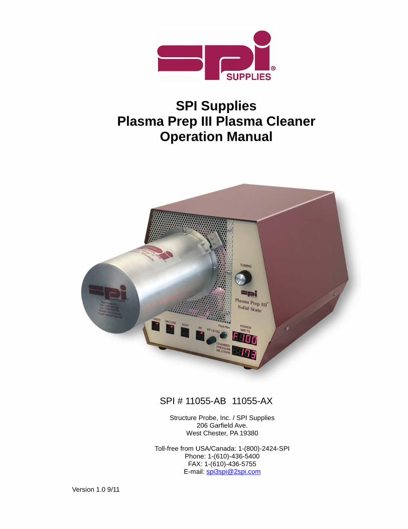
SPI Supplies
Plasma Prep III Plasma Cleaner Operation Manual
SPI # 11055-AB 11055-AX
Structure Probe, Inc. / SPI Supplies 206 Garfield Ave.
West Chester, PA 19380
Toll-free from USA/Canada: 1-(800)-2424-SPI Phone: 1-(610)-436-5400 FAX: 1-(610)-436-5755
E-mail: [email protected]

Version 1.0 9/11
Structure Probe, Inc. / SPI Supplies Street address for UPS, FedEx, DHL, other couriers, trucks 206 Garfield Ave. West Chester, PA 19380 Mailing address P.O. Box 656 West Chester, PA 19381-0656 USA Toll-free from USA/Canada: 1-(800)-2424-SPI Phone: 1-(610)-436-5400 FAX: 1-(610)-436-5755 E-mail: [email protected]
For further information regarding any of the other products designed and manufactured by SPI Supplies, contact your local representative or directly to SPI Supplies at the address above, or visit www.2spi.com
• Carbon and Sputter Coaters • Osmium Plasma Coaters • Ion Mills • Plasma Reactor for ashing and etching • High Vacuum Bench Top Evaporators • Critical Point Dryers • Electron Microscopy Supplies, Consumables and Accessories
Version 1.0 9/11
Warranty The SPI Supplies unit you have purchased is guaranteed to be free of defects in workmanship on the day of shipment. This warranty covers parts and labor for a period of one year, excluding shipping charges or consumables. Breakage of glassware is specifically excluded from this warranty. Proper use of your unit, according to the operation manual, should result in trouble-free operation. Any improper use of the SPI Supplies unit through modifications or unreasonable operating procedures will void this warranty.
Disclaimer SPI Supplies instruments are designed for simplicity of installation and operation. This manual provides full and complete information in both these areas. SPI Supplies therefore assumes no liability or responsibility of any kind for damage or injury resulting from incorrect installation or operation of the machine. If any questions arise, call SPI Supplies from the USA/Canada 1-800-2424-SPI or 1-610-436-5400 for assistance. For all other countries, contact our nearest agent or SPI Supplies directly. A listing of our agents may be found on our website at:
http://www.2spi.com/info/agents/

Version 1.0 9/11
1 Contents 1.1 Manual Layout
This Operation Manual is divided up into the following major sections, each section dealing with
specific topics, as follows: Section 1 – Contents Section 2 - Health and Safety General section which applies to all SPI Supplies products detailing the very important issues of Health
and Safety applicable when using sample preparation equipment. Section 3 - Introduction Introduces this manual. Section 4 - General Description Identifies each of the equipment items and provides an overview of their functions and how they work. Section 5 - Installation Instructions on how this Instrument should be installed and the connections which should be made
between the equipment items. Section 6 - Operation Instructions on how to start-up and run the instrument. Section 7 - Maintenance Instructions on routine maintenance checks and determining if the system is functioning correctly.
Information on how to identify faults in the system and how to rectify these faults. Section 8 – Spare parts and consumables Section 9 – Technical Diagrams

Version 1.0 9/11
1.2 Section Contents Section1 – Contents ................................................................................................... 4 1.1 Manual Layout ................................................................................................. 4 1.2 Section Contents ............................................................................................. 5 1.3 Illustrations ...................................................................................................... 6 Section 2 – Health and Safety ................................................................................... 7 2.1 Safety Policy .................................................................................................... 7 2.2 Servicing .......................................................................................................... 7 2.2.1 Disclaimer ..................................................................................................... 7 2.2.2 Operators and Service Engineers ................................................................ 7 2.3 Hazard Signals and Signs ............................................................................... 8 2.3.1 Hazard Signal Words – Definition ................................................................ 8 2.4 Good Working Practices .................................................................................. 9 2.5 Plasma Prep III Plasma Cleaner Specific Potential Safety Hazards ............... 9 Section 3 – Introduction ........................................................................................... 11 3.1 Return of Goods ............................................................................................ 11 3.2 Returns Procedure ........................................................................................ 11 Section 4 – Description ............................................................................................ 12 4.1 Overview ........................................................................................................ 12 4.2 Typical Plasma Process ................................................................................ 12 4.3 Technical Specifications ................................................................................ 13 4.4 Equipment Controls and Indicators ............................................................... 14 4.4.1 Front Panel ................................................................................................. 14 4.4.2 Rear Panel ................................................................................................. 15 4.5 Equipment Description .................................................................................. 16 4.5.1 RF Generator ............................................................................................. 16 4.5.2 Vacuum System ......................................................................................... 16 4.5.3 Gas Supply System .................................................................................... 16 4.5.4 Reaction Chamber ..................................................................................... 16 Section 5 – Installation ............................................................................................. 17 5.1 Site Requirements ......................................................................................... 17 5.2 Assembly ....................................................................................................... 17 5.2.1 Installing the Outer Chamber ..................................................................... 17 5.2.2 Engaging the TEM Specimen Stage Adapter............................................. 18 5.2.2 Vacuum Pump Installation .......................................................................... 18 5.2.3 Connecting the Process Gas ..................................................................... 19 Section 6 – Operation ............................................................................................... 20 6.1 Overview ........................................................................................................ 20 6.1.1 Initial Pump Down and Operation .............................................................. 20 6.1.2 Loading Samples ........................................................................................ 21 6.1.3 Shut Down Procedure ................................................................................ 21 6.2 Connecting the Plasma Prep III Process Controller ...................................... 22 Section 7 – Maintenance .......................................................................................... 23 7.1 Overview ........................................................................................................ 23

Version 1.0 9/11
7.2 O-ring Maintenance ....................................................................................... 23 7.3 Cleaning......................................................................................................... 23 7.4 Vacuum System Adjustments ........................................................................ 24 7.5 Replacement Parts ........................................................................................ 24 Section 8 – Replacement Parts ............................................................................... 25 Section 9 – Technical Diagrams .............................................................................. 26
1.3 Illustrations Figure 2.1 – Hazard Warning Symbols ........................................................................ 8 Figure 2.2 – Typical Warning Symbols ......................................................................... 8 Figure 4.4.1 – Front Panel .......................................................................................... 14 Figure 4.4.2 – Rear Panel .......................................................................................... 15 Figure 5.2.1 – Chamber Cross-section ...................................................................... 18 Table 8.1 – Replacement Parts .................................................................................. 25 Figure 9.1 – Logic Flow Chart .................................................................................... 26 Figure 9.2 – Plasma Prep III Plasma Cleaner Chassis Wiring Diagram .................... 27 Figure 9.3 – Plasma Prep III Plasma Cleaner Control Panel Schematic ................... 28 Figure 9.4 – Plasma Prep III Plasma Cleaner RF Control Board Schematic ............. 29

Version 1.0 9/11
2 HEALTH AND SAFETY Safety is very important when using any instrumentation and all users of our equipment should read this section. This section of the Manual applies to all specimen preparation equipment supplied by SPI Supplies, not just the particular instrument for which the manual refers. Included in this section are details on warning notations and good working practices.
2.1 Safety Policy This section contains important information relating to all health and safety aspects of the equipment. As such it should be read, and understood, by all personnel using the instrument whether as an operator or in a service capacity. SPI Supplies is committed to providing a safe working environment for its employees and those that use its equipment. SPI Supplies regularly reviews its operations to make environmental, health and safety improvements in line with applicable legislation. The equipment has been designed as a free-standing instrument. SPI Supplies cannot be held responsible for any damage, injury or consequential loss arising from the use of its equipment for any other purposes, or any unauthorized modifications made to the equipment. All service work carried out on the equipment should only be undertaken by suitably qualified personnel. SPI Supplies is not liable for any damage, injury or consequential loss resulting from servicing by unqualified personnel. SPI Supplies will also not be liable for damage, injury or consequential loss resulting from incorrect operation of the instrument or customer modification of the instrument.
2.2 Servicing 2.2.1 Disclaimer
All service work on the equipment should be carried out by qualified personnel. SPI Supplies cannot be liable for damage, injury or consequential loss resulting from servicing from unqualified personnel. SPI Supplies will also not be liable for damage, injury or consequential loss resulting from incorrect operation of the instrument or modification of the instrument.
2.2.2 Operators and Service Engineers A normal operator of the equipment not trained in or qualified for service work on the equipment and may cause a hazard to himself/herself or others if such work is attempted. Operators should therefore restrict themselves to the normal operation of the equipment and not remove covers from the electronic equipment or dismantling of the instruments, or otherwise attempt to thwart the intent of the safety interlock system. Service Engineers who are suitably trained to assess and isolate electrical, mechanical and vacuum hazards should be the only personnel who access the equipment.

Version 1.0 9/11
2.3 Hazard Signals and Signs
2.3.1 Hazard Signal Words - Definitions
WARNING Warnings are given where failure to observe the instruction could result in injury or death to people. CAUTION Cautions are given where failure to observe the instructions could result in damage to the equipment associated equipment and process.
Figure 2.1 - Hazard Warning Symbols
WARNING Do NOT depress button “P” as this will change the program.
Figure 2.2 - Typical Warning sign as shown in this Manual

Version 1.0 9/11
2.4 Good Working Practices It is essential that good hygienic working practices are adopted at all times especially in an ultra high vacuum or cleanroom environment and are generally of the “Common sense” type. Some simple good practice rules are:
If in doubt don't. If in doubt ask. When handling solvents wear face mask, gloves, apron and work only in a well ventilated
area. Mop up any spillages immediately, using procedures appropriate for the spilled material. When handling or decanting mineral oils wear protective clothing. Aerosols of mineral oils, such as that produced by gas ballasting, can prove to be hazardous
and an exhaust is recommended. Before attempting to service electrical apparatus, isolate from the mains. Treat all unknown substances as hazardous. Dispose of substances in an appropriate manner. Use the correct tool for the job. Keep a straight back and bend from the knees when lifting heavy objects. Wear protective clothing when using liquid nitrogen. Affix pressurised gas cylinders firmly to walls or racks. Use the correct regulating valves on
gas cylinders and always transport cylinders using the appropriate specialist trolley. Obey safety regulations regarding lifts, hoists and machine tools. Always make sure you understand a procedure well before attempting it for the first time.
2.5 Plasma Prep III Plasma Cleaner Specific Potential Safety Hazards The following Safety Hazards are specific to the SPI Supplies Plasma Prep III Plasma Cleaner
CAUTION Be sure to keep all vacuum parts, especially any O-rings or seals clean and free from excessive moisture, chips, dust etc. All such parts should be replaced if suspected of damage. CAUTION Do not handle any parts to be placed in the glass chamber with your bare hands. Contamination such as skin oil may cause trouble to the ultimate pressure.

Version 1.0 9/11
WARNING Use care when handling or installing the glass outer chamber, as they are extremely fragile. WARNING Be careful when handling the vacuum oil, because it is very hot just after the pump is operated. WARNING Never run the rotary vacuum pump without vacuum oil.
WARNING The used vacuum oil and oil mist traps should be disposed safely in accordance with all local and national safety and environmental requirements. WARNING Since the gas most commonly used in the Plasma Prep Plasma Cleaner is oxygen (O2), NO OPEN FLAME and NO SMOKING signs should be posted near the instrument.
WARNING
There are two micro-switch interlocks engineered into the Plasma Prep III Plasma Cleaner to prevent injury to operating personnel. They are: A. RF Shield Interlock – This switch cuts off AC power to the RF power supply. This ensures that the Plasma Prep III Plasma Cleaner will not function without the shield in place. B. Cover, Right Side, Center – This This switch shuts off all primary power to the Plasma Prep III Plasma Cleaner. It is to prevent the operation of the system while the top of the unit is off.
Version 1.0 9/11
3 INTRODUCTION This manual provides installation, operation and maintenance instructions for the Plasma Prep III Plasma Cleaner. You must use the Plasma Prep III Plasma Cleaner as described in this manual. Note that the servicing and maintenance procedures should only be carried out by qualified service personnel and it is essential that all users should read the Health and Safety section of this manual.
3.1 Return of Goods If goods are to be returned to SPI Supplies for repair or servicing the customer should contact SPI Supplies or their local distributor before shipment. A "Return Authorization Number" should be obtained in advance of any shipment. This number is to be clearly marked on the outside of the shipment. To obtain an RA#, contact our Customer Service Department and be sure to provide us with the following details: * SPI Invoice Number and Invoice Date (if applicable) * Method of shipment if applicable (post office, UPS, FedEx, Air Freight, etc.) * Product(s) in question * What is wrong with the product, or why do you want to make this return? This can also be done expeditiously through the SPI Supplies website at:
http://www.2spi.com/return_number.html For returns outside the United States, contact either your closest SPI Supplies agent (see http://www.2spi.com/info/agents/) or SPI Supplies in the USA by phone (1-610-436-5400), fax (1-610-436-5755), or by email ([email protected]).
3.2 Returns Procedure Warranty Claim All components are sold with a return to factory warranty (unless otherwise stated), which covers failure during the first 12 months after delivery. Returns must be sent courier paid, SPI Supplies will cover the return courier costs. This covers defects, which arise as a result of a failure in design or manufacturing. It is a condition of warranty that equipment must be used in accordance with the manufacturers instructions and not have been subjected to misuse. This warranty does not cover consumable items or glassware. To make a claim under the terms of this warranty provision contact the Customer Service Department at SPI Supplies. Chargeable Repairs Contact the Customer Service Department at SPI Supplies to obtain an estimate of repair costs. Service of equipment is generally completed within twenty working days after receipt of the equipment. A minimum evaluation fee is normally applied. Additional fees are charged as a per hour repair rate in addition to parts. Returns All returns to SPI Supplies are required to follow the procedure described above in Section 3.2. All returned items are required to have a Return Authorisation Number, which can also be obtained at www.2spi.com/return-number.html. Packaging and Shipping All goods shipped to the factory must be sealed and packed in a suitable carton. If the original packaging is not available SPI Supplies should be contacted for advice. DO NOT SHIP ANY GLASSWARE ASSEMBLED INSIDE THE UNIT. SPI Supplies will not be responsible for damage resulting from inadequate returns packaging or contamination of delicate structures by stray particles under any circumstances. All non-warranty goods returned to the factory must be sent courrier, pre-paid. They will be returned courrier, pre-paid and added to the final invoice unless otherwise arranged.

Version 1.0 9/11
4 DESCRIPTION 4.1 Overview The SPI Supplies Plasma Prep III Plasma Cleaner is a table-top plasma chemistry reactor designed to
provide plasma technology at a moderate cost. This simple-to-operate instrument can perform repeatable plasma chemical reactions with a minimum of automation. All controls are manual; however, where necessary, automatic monitors and controls take over to protect the equipment and the samples in the reactor.
The Plasma Prep III Plasma Cleaner comes equipped with an internally housed solid state RF generator. RF power is transferred from the power amplifier via a matching network to the reaction chamber. A variable capacitor provides a tuning control. Metering of the forward and reverse power and enables tuning of the instrument and is displayed on an LED selectable push button switch. The Plasma Prep III Plasma Cleaner is a small reactor that weighs under 31 pounds fully assembled, less vacuum pump. With the exception of the external vacuum pump, it is a fully self-contained machine. It consists of an RF generator and associated tuning circuits, a vacuum system with solenoid control valves, a constant feed gas supply system and a reaction chamber system, which includes one Pyrex® glass or quartz chamber and a polymer chamber seal including an adapter for the TEM Specimen Stage.
4.2 Typical Plasma Process The "Plasma Process" is accomplished through the use of a low pressure, RF induced gaseous discharge. The TEM Specimen Stage and related material or specimen is loaded into the reaction chamber using the appropriate adapter. The chamber is evacuated to a mild vacuum (approximately 250 mTorr) by a mechanical vacuum pump. A carrier gas is drawn through the chamber over the specimen. Radio frequency power is applied around the chamber (at 13.56MHz). This excites the carrier gas molecules and changes some of them into chemically active species. The mechanism employed in this process is one of oxidation. Electrons, produced by ionization of gas, gain energy in the electric field. Subsequent collisions between these energetic electrons and neutral gas molecules result in an energy transfer to the molecules producing chemically active atoms, free radicals, ions and free electrons. The combustion products, which are completely dissociated and harmless, are carried away in the gas stream. The unique property of this process is that it occurs near ambient temperatures without employing toxic chemicals.
As compared to traditional plasma etching of materials, plasma cleaning, using a far lower power, is designed literally to "tickle" the top surface of a material. For the purpose of removing thin adsorbed layers of contamination on a TEM foil sample for example, or on the sample Stage itself, a low power plasma cleaner will do the job just fine. Indeed, using argon for example, at higher power could actually "etch" and cause damage to the metal parts of the microscope stage. At less than 10 watt operation level, one is easily able to remove the slightly held contamination that is responsible for loss of contrast and image quality in most TEMs.

Version 1.0 9/11
4.3 Technical Specifications
Main Body
Model No. Plasma Prep III Plasma Cleaner (SPI# 11055-AB or AX) Weight 31 lbs / 14 kg
Height 10.5 inches / 26.7 cm
Width 11.8 inches / 30.0 cm Length 14.8 inches / 37.6 cm
RF Power 0 to 100 Watts RF Frequency 13.56 MHz – crystal controlled AC Power 100 to 240 V AC, 50/60 Hz (not including vacuum pump) Gas Introduction Sublimated gas is introduced into the gas reactor (chamber).
Evacuation Rotary Vane Vacuum Pump or Scroll Pump
Vacuum Pump Requirements
Vacuum Pump Capable of 50-100 liters/min. If using O2 or CF4, Fomblin® oil is recommended
Power 100 to 240 V AC, 50/60 Hz, 15 amp service Oil Mist Trap Please change element every 1,500 to 2,000 running hours
NOTE: This equipment complies with Title 47, Part 18 of the Federal Communications Commission Rules when operated as set forth in the accompanying instruction book. The fundamental (+/- 7 kHz) falls within the unlimited radiation ISM bands defined in FCC 18.301. Field strength levels of emissions outside the fundamental are below the limits of FCC 18.305. This ISM device complies with Canadian ICES-001.

Version 1.0 9/11
4.4 Controls and Indicators 4.4.1 Front Panel
Figure 4.4.1 – Front Panel 1 – Main Power Button – This button controls the main power to the Plasma Prep III Plasma Cleaner. When lit, main power is on. When unlit, main power is off. 2 – Vacuum Button – This button controls the vacuum interlock to the Plasma Prep III Plasma Cleaner. When lit, the chamber is under vacuum. When unlit, the chamber is not being evacuated or is isolated. 3 – Vent Button – This button controls the venting of the chamber. When lit, the chamber is being vented. When unlit, the chamber is not being vented. 4 – RF Button – This button turns the RF power generator on and off. When lit, the RF power is on. When unlit, the RF power is off. 5 – RF Level Dial – This dial controls the intensity of the RF power being generated. Turning the dial clockwise will increase the RF power. Turning the dial counter-clockwise will decrease the RF power. 6 – Fwd/Rev Button – This button will toggle the forward and reverse power displays. An “F” indicates that forward power is being displayed. An “r” indicates reverse power is being displayed.

Version 1.0 9/11
7 – Tuning Dial – This dial is used to tune the RF field. Tuning should be done in such as way as to maximize the forward power, while keeping the reverse power to a minimum. 8 – Power Display – This display shows the current power being generated in watts. 9 – Chamber Pressure Display – This display shows the current chamber pressure in mTorr. 4.4.2 Rear Panel
Figure 4.4.2 – Rear Panel
10 – Vacuum Inlet – Flange for vacuum hose (NW16) connected to the Plasma Prep III Plasma Cleaner. 11 – Gas Inlet – Gas supply is connected to the Plasma Prep III Plasma Cleaner. This is a barbed fitting for a standard tubing. 12 – Power Inlet and Fuses – Main power cord connection to the Plasma Prep III Plasma Cleaner. 13 – Comm Port – Communication Port to connect to the optional Plasma Prep III Process Control Unit (SPI #11052-AB). This unit allows the control input of two gasses (each separately, or mixed) as well as a programmable timer system interfaced tot he Plasma Prep III Plasma Cleaner.

Version 1.0 9/11
4.5 Equipment Description 4.5.1 RF Generator
RF Generator - The RF power source includes a solid state oscillator operating at 13.56 MHz, the FCC-authorized industrial frequency. A solid state linear driver and amplifier supplies a continuous wave power from 1 watt to a maximum of 100 watts. Power transfer to the reaction chamber is accomplished via an impedance matching network.
4.5.2 Vacuum System Vacuum System - The vacuum system includes the vacuum pump (not supplied as part of the Plasma Prep III Plasma Cleaner), the vacuum hose, the vacuum valves and the control circuitry. The vacuum valve switch is interlocked with the RF generator switch to prevent the RF power from coming on unless the vacuum valve is energized. An internal vacuum meter is used to monitor chamber pressure.
4.5.3 Gas Supply System Gas Supply System - The gas supply system for the Plasma Prep Plasma Cleaner consists of the gas delivery system inside the reaction chamber. This delivery system is a glass tube sealed on the inner end and perforated along its bottom surface. Sliding the tubing over the barbed fittings on the glass chamber makes connections to the delivery tube. 4.5.4 Reaction Chamber Reaction Chamber - The reaction chamber sub-system consists of an upper and lower electrode, a Pyrex glass outer reaction chamber, and a polymer adapter seal (See Fig. 2-1). (NOTE: For CF4 operation, a quartz chamber should be used, though care should be taken in using such a reactive gas with a TEM Specimen Stage). The chamber is sealed with a flat gasket, which seats against a raised lip on the polymer adapter portion. The gas delivery tube feeds through the back of the outer chamber section. This chamber section also provides connection to the vacuum hose by a glass tube joined at the front of the chamber. This arrangement provides for the best gas conduction flow and results in repeatable, dependable processing.
5 INSTALLATION 5.1 Site Requirements
There are very few constraints on the location of the Plasma Prep III Plasma Cleaner. The machine should be operated in a well ventilated area away from any corrosive fumes. The supply from the cooling fan should

Version 1.0 9/11
not be obstructed. The machine's exhaust (the vacuum pump exhaust) should be vented away from operating personnel. The machine should be far enough away from high voltage equipment to prevent possible high voltage interference. Finally, please ensure the you have the following available:
1) Vacuum pump (See Sec 4.3)) 2) Gas supply – Oxygen (O2) or other reactive gas (industrial grade), with approved regulator
capable of supplying 5 PSIG and shut off valve 3) 100 to 240 V AC, 50/60 Hz, 15 amp service
5.2 Assembly
The only assembly required when installing the Plasma Prep Plasma Cleaner consists of putting the outer chamber into the electrodes, and connections for the gas, vacuum, and electrical power.
5.2.1 Installing The Outer Chamber With the machine resting on a convenient work surface, remove the four screws (two on each side) at the bottom of the sheet metal top cover. Remove the top cover only.
A. Remove the four screws on the front panel. Be careful of the wire connection to the terminal block on the chassis and carefully lay the panel to the side. Note that the adapter chamber seal is held against the front panel with retaining wires. These should not be removed at this time.
B. Remove the two nylon screws and spacing bushings on the left side and loosen the two nylon
screws on the right side.
C. Remove the outer chamber from its shipping container. Make sure no packing material is in the chamber.
D. Locate the exhaust manifold at the front-center floor of the cabinet. Loosen the brass compression
nut to accept the extension of the outer chamber for fitting into vacuum manifold.
E. Lift the upper shell (cover will "hinge" on the two loosened screws). Slide chamber to the rear of the shell and engage the pre-fitted silicon tube.
F. Following insertion of the glass extension inside the manifold, tighten the knurled compression
nut, finger tight. DO NOT OVERTIGHTEN as this can affect the vacuum. Care must be used to ensure that the silicon tubes are firmly in place and the glass neck fits into the vacuum manifold without it being cocked. If not properly aligned, the glass neck can break upon use.
G. Replace the two nylon screws that were removed from the left side and re-tighten them. DO
NOT OVERTIGHTEN as this can damage the threads.
H. The upper tube will attach over the barbed fitting on the gas inlet valve. The tube from the middle of the chamber is not used as part of the standard operation. A cap is placed over this fitting.

Version 1.0 9/11
Figure 5.2.1 – Chamber Cross-section
CAUTION Never use metallic screws in place of the nylon screws. Metal, even in small amounts, will short circuit the chamber’s electrodes.
5.2.2 Engaging The TEM Specimen Stage Adapter
A. Close the door with the adapter and ensure that the door latch is secure. B. Ensuring that the chamber adapter seal is seated against the outer chamber at the O-ring,
release the wires retaining the adapter chamber seal and allow the seal to align to the outer chamber.
C. Use the blanking plug to seal the chamber when not using a TEM Specimen Stage.
5.2.3 Vacuum Pump Installation
A. Set the pump horizontally on the floor, close to where the instrument has been placed.

Version 1.0 9/11
B. Ensure that the pump is filled with the appropriate oil. If not, fill with the appropriate oil. Ensure that the drain plug is closed, and remove the fill cap. Pour the appropriate oil into the pump until the oil level indicator shows the proper amount has been added.
C. Connect the flexible metal vacuum pipe to the flange connection at the rear of the Plasma Prep III
Plasma Cleaner and to the vacuum pump using the O-rings and clamps provided.
CAUTION Please be sure to use the appropriate pump manufacturer vacuum oil. For oils suitable for various pumps, please contact your SPI Supplies Representative.
CAUTION Be sure to keep the vacuum parts, especially the O-ring on the clamp center ring and everything it may contact clean and free from excessive moisture, chips, dust etc. Also, be sure not to damage the surface of them. Chips or visible dust, which enter the pump, may cause mechanical failure. Evacuating excessive moisture will not only be harmful in obtaining ultimate pressure, but will also corrode the pump during prolonged operation.
WARNING Do not run the pump if the oil is below recommended levels. It may damage the pump.
5.2.4 Connecting the Process Gas Connect the regulated gas supply hose to the quarter-inch fitting GAS IN, Item 12 of Figure 3-2, located at
rear of the machine.

Version 1.0 9/11
6 OPERATION 6.1 Overview
Operation of the Plasma Prep Plasma Cleaner consists of loading the TEM Specimen Stage, evacuating the reaction chamber, applying the process gas and applying the energizing RF power. The RF amplifier must be resonated and the power level adjusted to the appropriate level. Upon completion of the process, the RF power switch is turned off, and then the vacuum valve switch is turned off. The primary power must remain on for the chamber to vent back to atmospheric pressure. After the vacuum valve switch is turned off, the VENT valve switch must be energized. The main power can only be turned off after the vent switch is energized. The Plasma Prep III Plasma Cleaner comes with a BLANK and one or more adapters for your TEM Specimen Stages. These adapters are designed to work with the specific TEM Specimen Stage so that a vacuum good fit is obtained. While some of these adapters can be used for similar TEM Specimen Stages, the identification and use of an adapter for each Stage is suggested.
6.1.1 Initial Pump Down and Operation
A. Power switch should be OFF (Red LED light will remain unlit). The “POWER LEVEL” control dial should be turned completely counter-clockwise.
B. Start the vacuum pump. Turn on the AC power by depressing the “POWER” button.
C. Fit the BLANK adapter into the so that it is fully engaged and the o-rings make a good seal.
D. Turn on the vacuum by pressing the “VACUUM” button. Turn on the process gas, and ensure
the flow rate is set to 5 PSIG. Allow the unit to pump down for approximately one minute, or until the chamber pressure reads approximately 250 mTorr.
E. Fit the RF shield over the adapter, align the pins, and secure it by twisting into place. Note that
at this time the micro switch is engaged. This interlock allows the RF power to be engaged. F. Turn on the RF power by pressing the “RF POWER BUTTON”. Turn the “POWER LEVEL”
control dial clockwise until the LED readout displays a power of approximately 10 watts. Adjust the “TUNING” control dial until the reading is maximized. Pressing the “FWD-REV” button will change the LED readout from Forward Power (F) to Reverse Power (R). Select the Reverse Power, and adjust the “TUNING” control dial until a minimum reading is achieved.
6.1.2 Loading Samples

Version 1.0 9/11
A. Load the TEM Specimen Stage with the sample of interest. (Or run without a sample). Feed the
TEM Specimen Stage into the adapter provided.
B. Turn the “POWER LEVEL” control dial fully counter-clockwise.
C. Turn the “RF POWER” button OFF.
D. Turn the “VACUUM” button OFF.
E. Press the “VENT” button. This will vent the chamber. This process should take approximately one minute. The RF shield can now be disengaged from the body. The BLANK or TEM Specimen Stage can now be removed.
F. The TEM Stage is carefully fitting into the proper TEM adapter and the assembly is put into the
door adapter.
G. The Stage is now pumped down as described in 6.1.1.
NOTE 1: The Plasma Prep III Plasma Cleaner is capable of running at up to 100 watts power. For most TEM Stage applications, that are interested in the cleaning of TEM specimen stages, this is more power than is needed. Most operations are on the order of 10 watts, though power as low as one watt can be achieved. NOTE 2: Before the Plasma Prep III Plasma Cleaner is run for the first time, allow the unit to run for one hour before use. This will eliminate any contamination which might be present in the chamber. Either room air or oxygen (O2) can be used for this purpose.
6.1.3 Shut Down Procedure
A. After the last sample has been treated, special precautions should be taken to prevent contaminating the exhaust line with pump oil.
B. Turn off the process gas.
C. Remove any sample that may be in the chamber by following the steps outlined in 6.1.2.
D. Turn off the vacuum pump.
E. Place the BLANK in the Door Adapter. The System is typically not kept under vacuum when
not in use.
F. Turn off the Main Power to the system.

Version 1.0 9/11
6.2 Connecting the Plasma Prep III Process Controller
The Plasma Prep III Plasma Cleaner can be used with the optional Plasma Prep III Process Controller. This system provides for multiple gas inputs, either individually or mixed, as well as allowing a process timing of an operation. The Process Controller is placed on top of the Plasma Prep III Plasma Cleaner and is connected through the COMM port in the back of the system. For complete instruction for installation and operation of the Process Controller, please refer to the Plasma Prep III Process Controller manual.

Version 1.0 9/11
7 MAINTENANCE 7.1 Overview
The Plasma Prep III Plasma Cleaner is a system designed for easy routine maintenance and should provide many years of service if routine procedures are used. Maintenance on the Plasma Prep III Plasma Cleaner consists of cleaning and replacing such parts as O-rings. The outer chamber will need to be replaced only in the unlikely circumstance of breakage. Any other repairs should be performed by SPI Supplies qualified technicians.
7.2 O-ring Maintenance
The Plasma Prep III Plasma Cleaner has a few o-rings that should be examined at regular intervals. While the low RF wattage that are typically run on this system, will mean longer time periods before the o-rings are degraded and in need of replacement, a careful monitoring of the o-rings will help to keep the system running at good pressures and conditions. If there is a noticeable degradation of the vacuum, one should check on the o-rings initially. The most likely o-ring in need of replacement is the main gasket between the outer chamber and the door adapter seal. This can easily be examined by carefully opening the door and removing the gasket. Care must be taken when opening the door as the springs, which hold the adapter to the chamber may become loose. Similarly, when replacing the from door adapter, care should be used to ensure that the gasket is fully in contact with the outer chamber before latching the door. Failure to do so may cause vacuum problems. The gasket, if in good condition, may be lightly greased using an Apiezon grease. In cases where no grease is desired, the o-rings can be run without using any grease, but should be changed on a more regular basis. Other o-rings are found in the neck of the out chamber and on the TEM Specimen Stage adapters. The outer chamber o-ring will rarely need changing while the adapter o-ring will need changing based on wear from use.
7.3 Cleaning Cleaning consists of a routine procedure, which should be performed periodically. This schedule will depend on frequency of use, type of materials processed, and the environment in which the machine operates. Routine Procedure: Cleaning of the outer chamber is rarely needed as it is rarely likely to become contaminated. For light contamination, running oxygen plasma for a few minutes should be enough to clean the chamber. For more difficult contaminants (inorganic films and residues), use standard laboratory cleaning procedures. Removal of the outer chamber would need to be done and wash the chamber with a test tube brush and a good laboratory detergent. If this is not effective, it will be necessary to use an oxidizing agent. Refer to the “Handbook of Chemistry and Physics” for a suitable agent.

Version 1.0 9/11
7.4 Vacuum System Adjustments
The process gas flow is adjusted by the internal needle valve located at the rear top of the instrument, just after the connector for the gas line. The needle valve is pre-set so that the pressure in the chamber should read approximately 250 mTorr with the chamber empty and without any gas input. The needle valve typically does not need adjustment. If a significant difference in pressure is observed, check for possible leaks at the O-rings and tubing before adjusting the needle valve setting. The needle valve adjustment is done by turning the needle clockwise or counter-clockwise. The chamber back-fill to atmosphere is controlled by a bleed valve solenoid located on the left side of the chassis. The adjustment is a setscrew. Turning the setscrew clockwise closes the valve (and increases the time to back-fill the chamber to atmospheric pressure). Turning the setscrew counter-clockwise opens the valve (and decreases the time to back-fill the chamber to atmospheric pressure). The vacuum pump should be serviced on a frequent and regular schedule. Pump fluids should be changed on a regular schedule, per the pump manufacturer’s recommendation. The life of the oil mist trap depends on the various conditions under which the pump is used. In most cases, the oil mist trap elements should be changed every 1,500 to 2,000 running hours.

Version 1.0 9/11
8 REPLACEMENT PARTS Below are typical consumable or replacement parts used in the operation of the Plasma Prep III Plasma Cleaner. For other components not listed here, please contact SPI Supplies.
SPI Part Number DESCRIPTION 11008-AB 4” ID Pyrex Inner Chamber 11009-AB 4” ID Pyrex Outer Chamber 11010-AB 4” ID O-Ring 11013-AB Solenoid Valve, Straight Thru 11014-AB Solenoid Valve, Metering 11024-AB O-Ring for Outer Chamber 11026-AB 4” ID Quartz Inner Chamber 11027-AB 4” ID Quartz Outer Chamber
Table 8.1 Consumables and Replacement Parts

Version 1.0 9/11
9 TECHNICAL DIAGRAMS
Figure 9.1 – Logic Flow Chart

Version 1.0 9/11
Figure 9.2 – Plasma Prep III Plasma Cleaner Chassis Wiring Diagram

Version 1.0 9/11
Figure 9.3 – Plasma Prep III Plasma Cleaner Control Panel Schematic

Version 1.0 9/11
Figure 9.4 – Plasma Prep III Plasma Cleaner RF Control Board Schematic