
SPHERICAL ROLLER BEARING UNITS · 2019-12-22 · 5 6 Models and Features SPHERICAL ROLLER BEARING...
19
f y h b e a r i n g s . c o m CATALOG NO.12020b ® SPHERICAL ROLLER BEARING UNITS
Transcript of SPHERICAL ROLLER BEARING UNITS · 2019-12-22 · 5 6 Models and Features SPHERICAL ROLLER BEARING...
fyhbearings.com
CATALOG NO.12020b2017.05
®
®
SPHERICAL ROLLER BEARING UNITS
1 2
EXTRATOUGH
3 4
http://www.fyhbearings.com/html/nomenclature_r.html
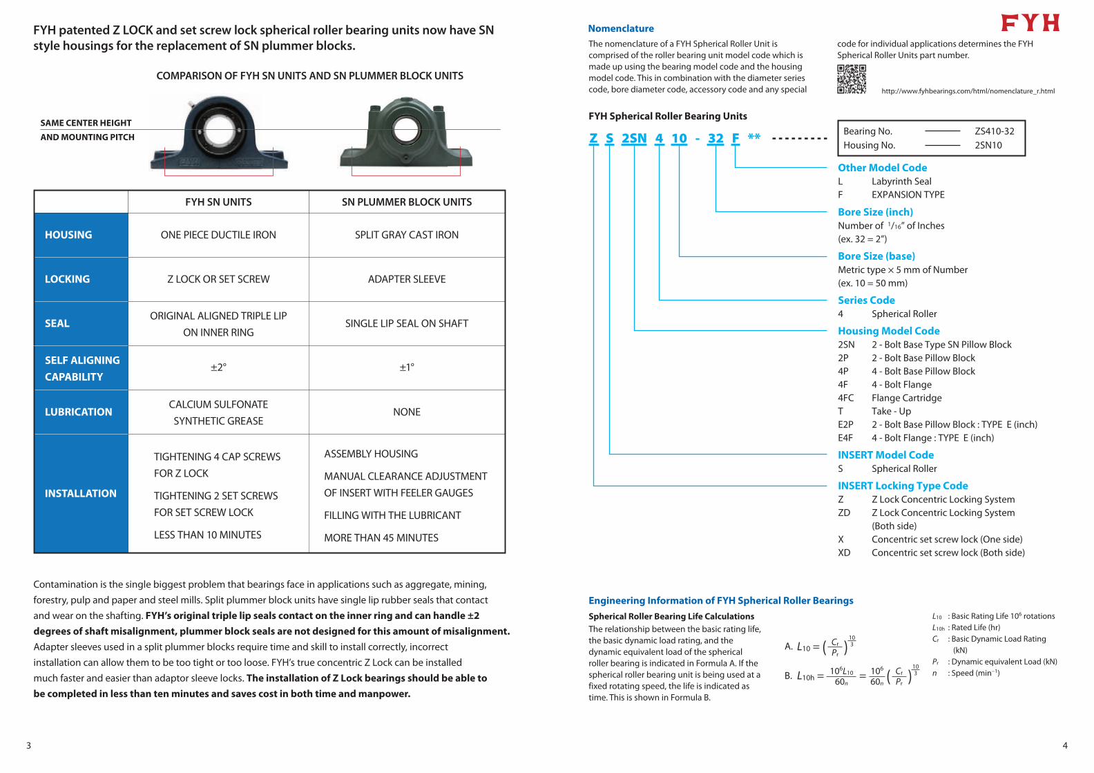
NomenclatureThe nomenclature of a FYH Spherical Roller Unit is comprised of the roller bearing unit model code which is made up using the bearing model code and the housing model code. This in combination with the diameter series code, bore diameter code, accessory code and any special
code for individual applications determines the FYH Spherical Roller Units part number.
FYH Spherical Roller Bearing Units
Other Model CodeL Labyrinth SealF EXPANSION TYPE
Bore Size (inch)Number of 1/16” of Inches(ex. 32 = 2”)
Bore Size (base)Metric type × 5 mm of Number(ex. 10 = 50 mm)
Housing Model Code2SN 2 - Bolt Base Type SN Pillow Block2P 2 - Bolt Base Pillow Block4P 4 - Bolt Base Pillow Block4F 4 - Bolt Flange4FC Flange CartridgeT Take - UpE2P 2 - Bolt Base Pillow Block : TYPE E (inch)E4F 4 - Bolt Flange : TYPE E (inch)
INSERT Model CodeS Spherical Roller
INSERT Locking Type CodeZ Z Lock Concentric Locking SystemZD Z Lock Concentric Locking System (Both side)X Concentric set screw lock (One side)XD Concentric set screw lock (Both side)
Z S 2SN 4 10 - 32 F ** Housing No.Bearing No. ZS410-32
2SN10
Series Code4 Spherical Roller
Engineering Information of FYH Spherical Roller Bearings
Spherical Roller Bearing Life CalculationsThe relationship between the basic rating life, the basic dynamic load rating, and the dynamic equivalent load of the spherical roller bearing is indicated in Formula A. If the spherical roller bearing unit is being used at a fixed rotating speed, the life is indicated as time. This is shown in Formula B.
L10 : Basic Rating Life 106 rotationsL10h : Rated Life (hr)Cr : Basic Dynamic Load Rating
(kN)Pr : Dynamic equivalent Load (kN)n : Speed (min−1)
L10 = ( )
L10h = = ( )
A.
B.
Cr
Pr
103
103106L10
60n
106
60n
Cr
Pr
5 6
Models and FeaturesSPHERICAL ROLLER BEARING UNITS
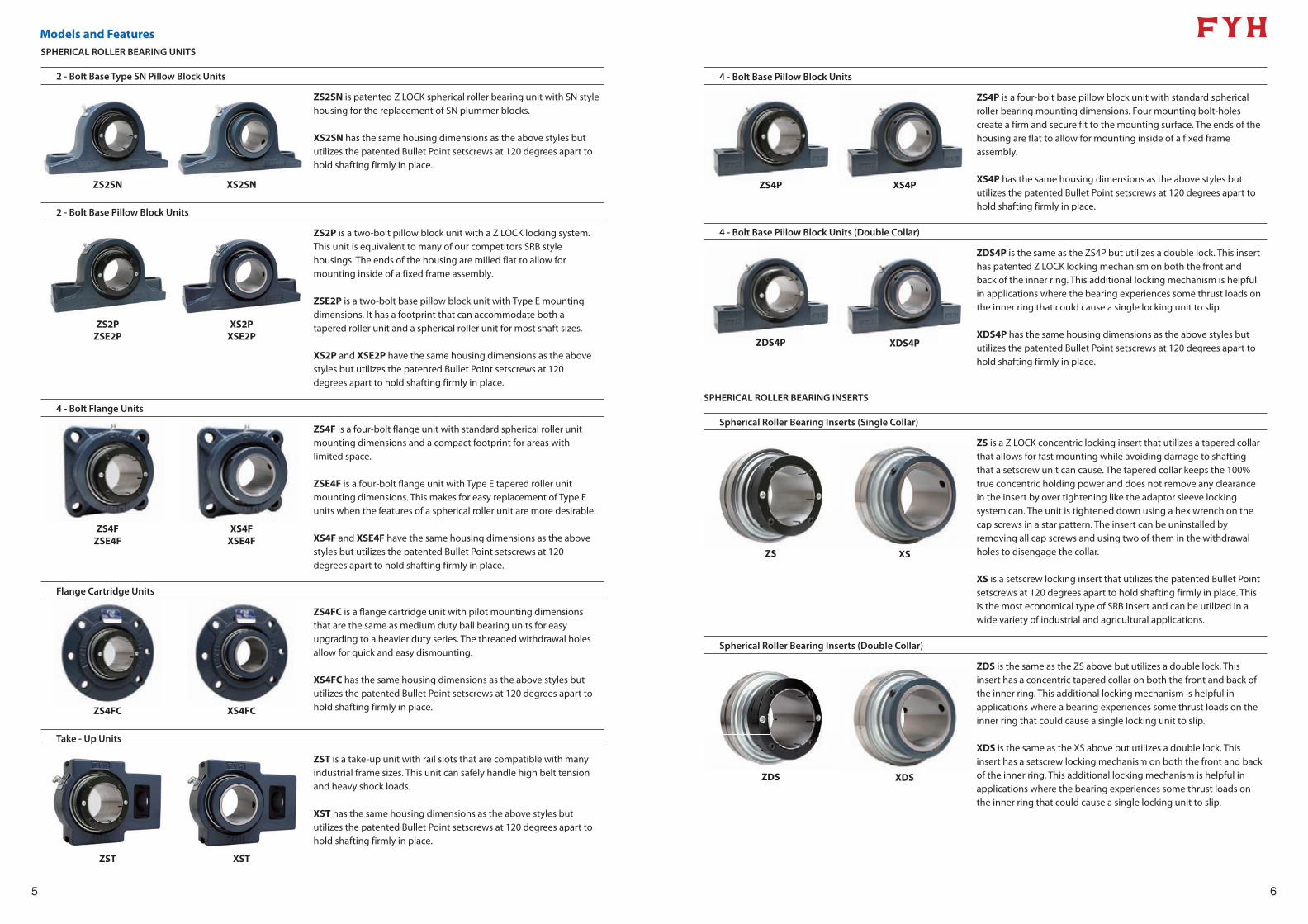
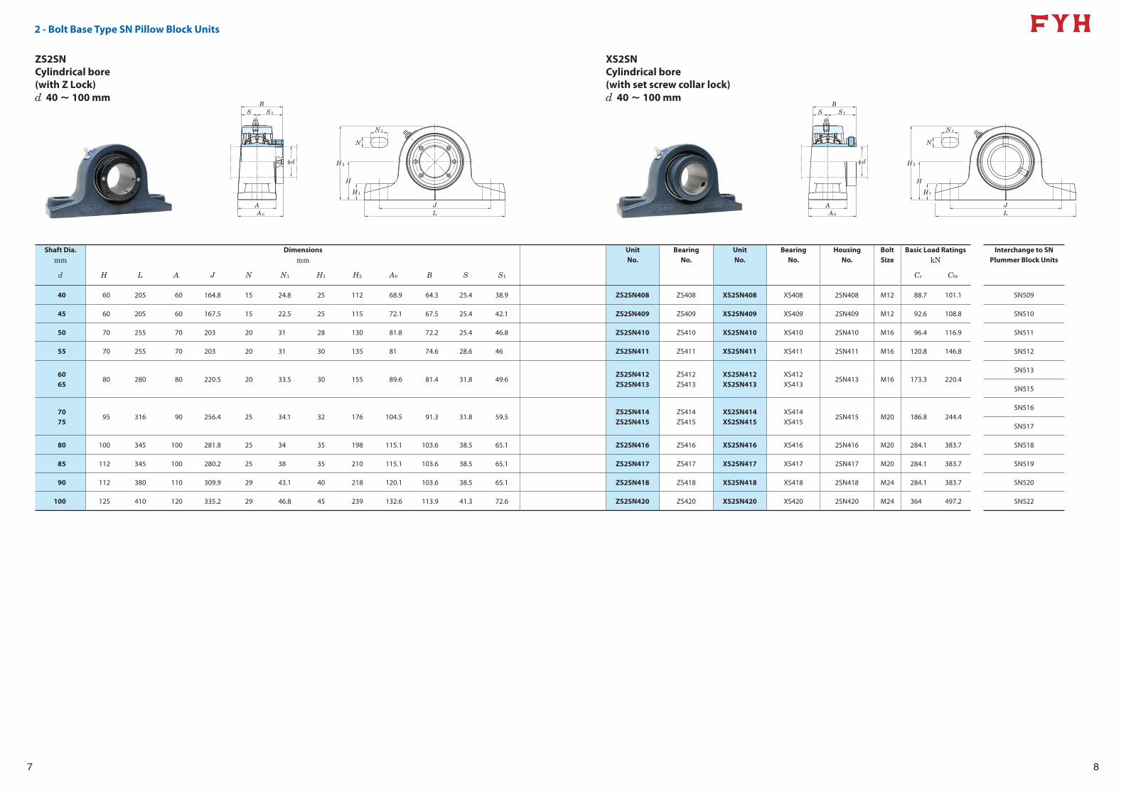
2 - Bolt Base Type SN Pillow Block Units
ZS2SN XS2SN
ZS2SN is patented Z LOCK spherical roller bearing unit with SN style housing for the replacement of SN plummer blocks.
XS2SN has the same housing dimensions as the above styles but utilizes the patented Bullet Point setscrews at 120 degrees apart to hold shafting firmly in place.
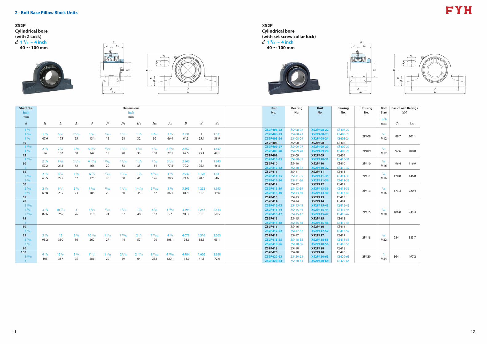
2 - Bolt Base Pillow Block Units
ZS2PZSE2P
XS2PXSE2P
ZS2P is a two-bolt pillow block unit with a Z LOCK locking system. This unit is equivalent to many of our competitors SRB style housings. The ends of the housing are milled flat to allow for mounting inside of a fixed frame assembly.
ZSE2P is a two-bolt base pillow block unit with Type E mounting dimensions. It has a footprint that can accommodate both a tapered roller unit and a spherical roller unit for most shaft sizes.
XS2P and XSE2P have the same housing dimensions as the above styles but utilizes the patented Bullet Point setscrews at 120 degrees apart to hold shafting firmly in place.
4 - Bolt Flange Units
ZS4FZSE4F
XS4FXSE4F
ZS4F is a four-bolt flange unit with standard spherical roller unit mounting dimensions and a compact footprint for areas with limited space.
ZSE4F is a four-bolt flange unit with Type E tapered roller unit mounting dimensions. This makes for easy replacement of Type E units when the features of a spherical roller unit are more desirable.
XS4F and XSE4F have the same housing dimensions as the above styles but utilizes the patented Bullet Point setscrews at 120 degrees apart to hold shafting firmly in place.
Flange Cartridge Units
ZS4FC XS4FC
ZS4FC is a flange cartridge unit with pilot mounting dimensions that are the same as medium duty ball bearing units for easy upgrading to a heavier duty series. The threaded withdrawal holes allow for quick and easy dismounting.
XS4FC has the same housing dimensions as the above styles but utilizes the patented Bullet Point setscrews at 120 degrees apart to hold shafting firmly in place.
Take - Up Units
ZST XST
ZST is a take-up unit with rail slots that are compatible with many industrial frame sizes. This unit can safely handle high belt tension and heavy shock loads.
XST has the same housing dimensions as the above styles but utilizes the patented Bullet Point setscrews at 120 degrees apart to hold shafting firmly in place.
4 - Bolt Base Pillow Block Units
ZS4P XS4P
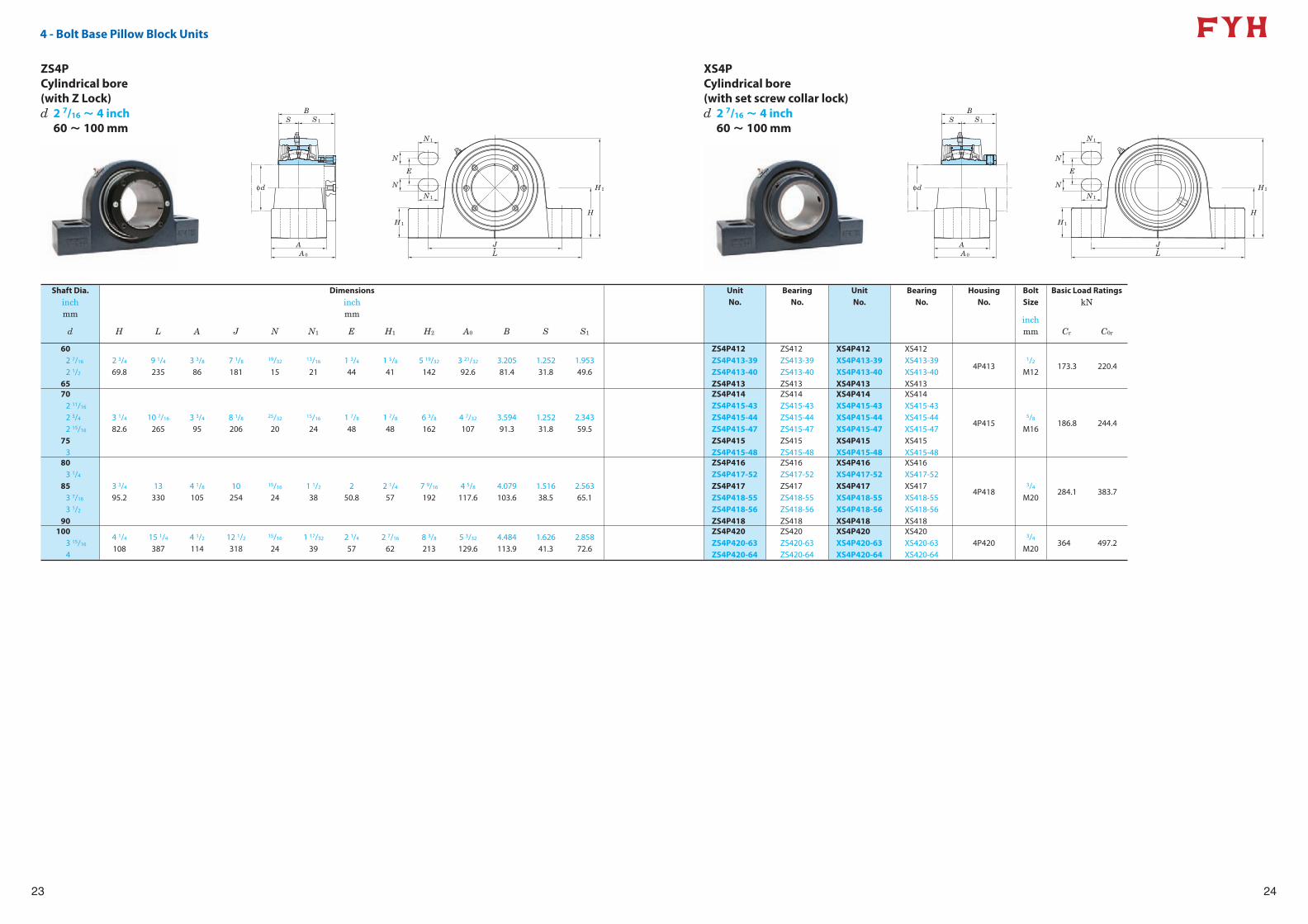
ZS4P is a four-bolt base pillow block unit with standard spherical roller bearing mounting dimensions. Four mounting bolt-holes create a firm and secure fit to the mounting surface. The ends of the housing are flat to allow for mounting inside of a fixed frame assembly.
XS4P has the same housing dimensions as the above styles but utilizes the patented Bullet Point setscrews at 120 degrees apart to hold shafting firmly in place.
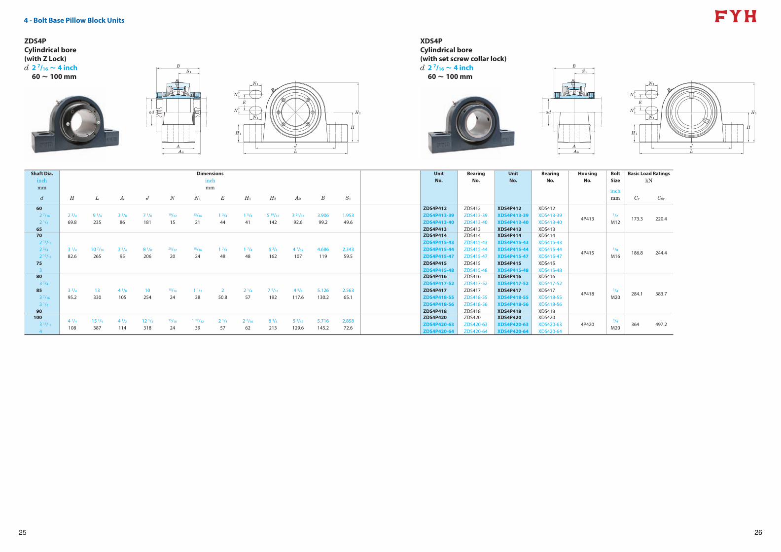
4 - Bolt Base Pillow Block Units (Double Collar)
ZDS4P XDS4P
ZDS4P is the same as the ZS4P but utilizes a double lock. This insert has patented Z LOCK locking mechanism on both the front and back of the inner ring. This additional locking mechanism is helpful in applications where the bearing experiences some thrust loads on the inner ring that could cause a single locking unit to slip.
XDS4P has the same housing dimensions as the above styles but utilizes the patented Bullet Point setscrews at 120 degrees apart to hold shafting firmly in place.
SPHERICAL ROLLER BEARING INSERTS
Spherical Roller Bearing Inserts (Single Collar)
ZS XS
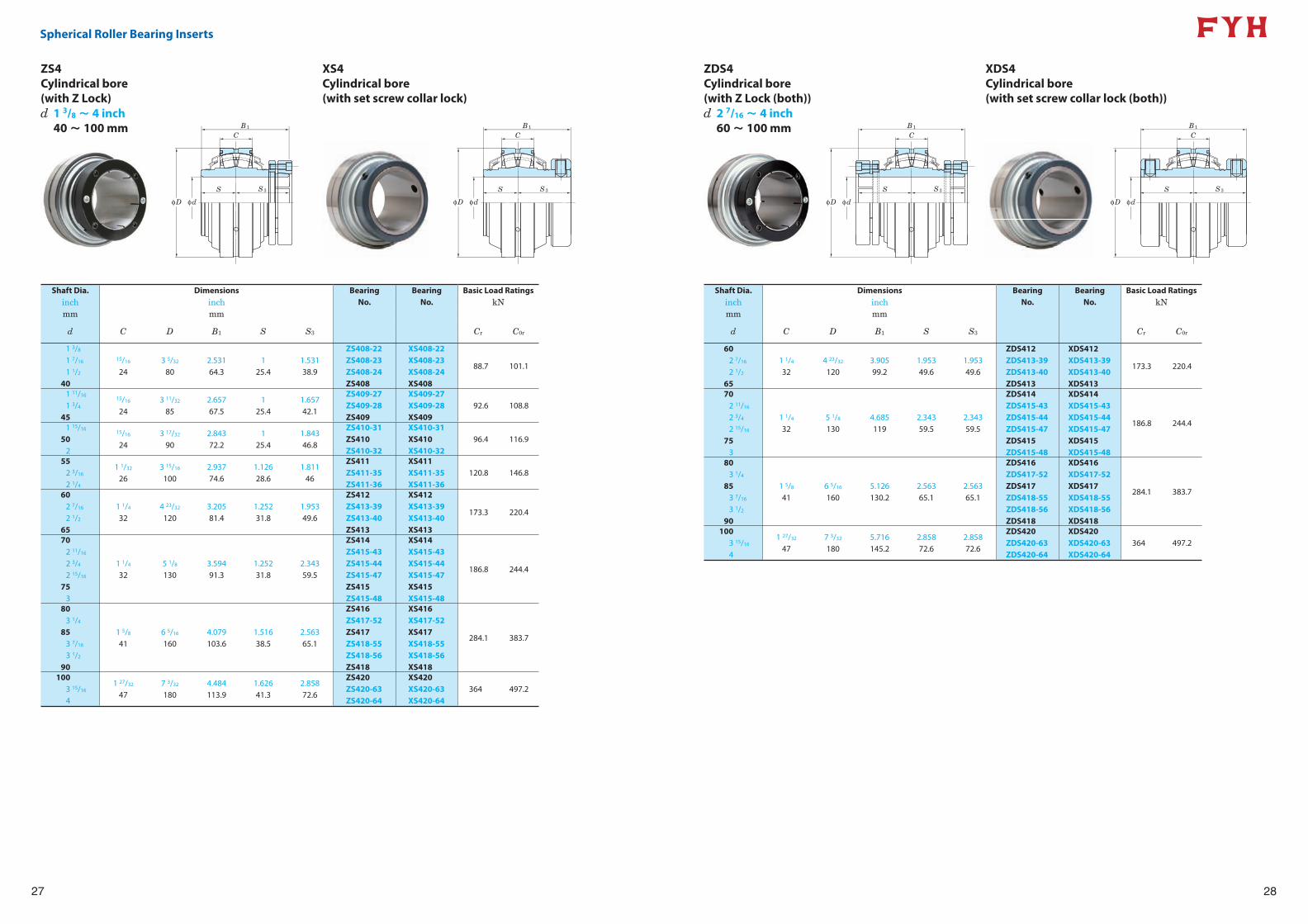
ZS is a Z LOCK concentric locking insert that utilizes a tapered collar that allows for fast mounting while avoiding damage to shafting that a setscrew unit can cause. The tapered collar keeps the 100% true concentric holding power and does not remove any clearance in the insert by over tightening like the adaptor sleeve locking system can. The unit is tightened down using a hex wrench on the cap screws in a star pattern. The insert can be uninstalled by removing all cap screws and using two of them in the withdrawal holes to disengage the collar.
XS is a setscrew locking insert that utilizes the patented Bullet Point setscrews at 120 degrees apart to hold shafting firmly in place. This is the most economical type of SRB insert and can be utilized in a wide variety of industrial and agricultural applications.
Spherical Roller Bearing Inserts (Double Collar)
ZDS XDS
ZDS is the same as the ZS above but utilizes a double lock. This insert has a concentric tapered collar on both the front and back of the inner ring. This additional locking mechanism is helpful in applications where a bearing experiences some thrust loads on the inner ring that could cause a single locking unit to slip.
XDS is the same as the XS above but utilizes a double lock. This insert has a setscrew locking mechanism on both the front and back of the inner ring. This additional locking mechanism is helpful in applications where the bearing experiences some thrust loads on the inner ring that could cause a single locking unit to slip.
H
H2
S1S
A0
A
B
φd
H1
N1
N
JL
7
2 - Bolt Base Type SN Pillow Block Units
H
H2
S1S
A0
A
B
φd
H1
N1
N
JL
8
ZS2SNCylindrical bore (with Z Lock)
XS2SNCylindrical bore (with set screw collar lock)
Shaft Dia. Dimensions Unit Bearing Unit Bearing Housing Bolt Basic Load Ratings Interchange to SNmm mm No. No. No. No. No. Size kN Plummer Block Units
d H L A J N N1 H1 H2 A0 B S S1 Cr C0r
40 60 205 60 164.8 15 24.8 25 112 68.9 64.3 25.4 38.9 ZS2SN408 ZS408 XS2SN408 XS408 2SN408 M12 88.7 101.1 SN509
45 60 205 60 167.5 15 22.5 25 115 72.1 67.5 25.4 42.1 ZS2SN409 ZS409 XS2SN409 XS409 2SN409 M12 92.6 108.8 SN510
50 70 255 70 203 20 31 28 130 81.8 72.2 25.4 46.8 ZS2SN410 ZS410 XS2SN410 XS410 2SN410 M16 96.4 116.9 SN511
55 70 255 70 203 20 31 30 135 81 74.6 28.6 46 ZS2SN411 ZS411 XS2SN411 XS411 2SN411 M16 120.8 146.8 SN512
6065
80 280 80 220.5 20 33.5 30 155 89.6 81.4 31.8 49.6ZS2SN412ZS2SN413
ZS412ZS413
XS2SN412XS2SN413
XS412XS413
2SN413 M16 173.3 220.4SN513
SN515
7075
95 316 90 256.4 25 34.1 32 176 104.5 91.3 31.8 59.5ZS2SN414ZS2SN415
ZS414ZS415
XS2SN414XS2SN415
XS414XS415
2SN415 M20 186.8 244.4SN516
SN517
80 100 345 100 281.8 25 34 35 198 115.1 103.6 38.5 65.1 ZS2SN416 ZS416 XS2SN416 XS416 2SN416 M20 284.1 383.7 SN518
85 112 345 100 280.2 25 38 35 210 115.1 103.6 38.5 65.1 ZS2SN417 ZS417 XS2SN417 XS417 2SN417 M20 284.1 383.7 SN519
90 112 380 110 309.9 29 43.1 40 218 120.1 103.6 38.5 65.1 ZS2SN418 ZS418 XS2SN418 XS418 2SN418 M24 284.1 383.7 SN520
100 125 410 120 335.2 29 46.8 45 239 132.6 113.9 41.3 72.6 ZS2SN420 ZS420 XS2SN420 XS420 2SN420 M24 364 497.2 SN522
d 40 ~ 100 mm d 40 ~ 100 mm
H
H2
S1
A0
A
B
φd
H1
N1
N
JL
9
2 - Bolt Base Type SN Pillow Block Units
H
H2
S1
A0
A
B
φd
H1
N1
N
JL
10
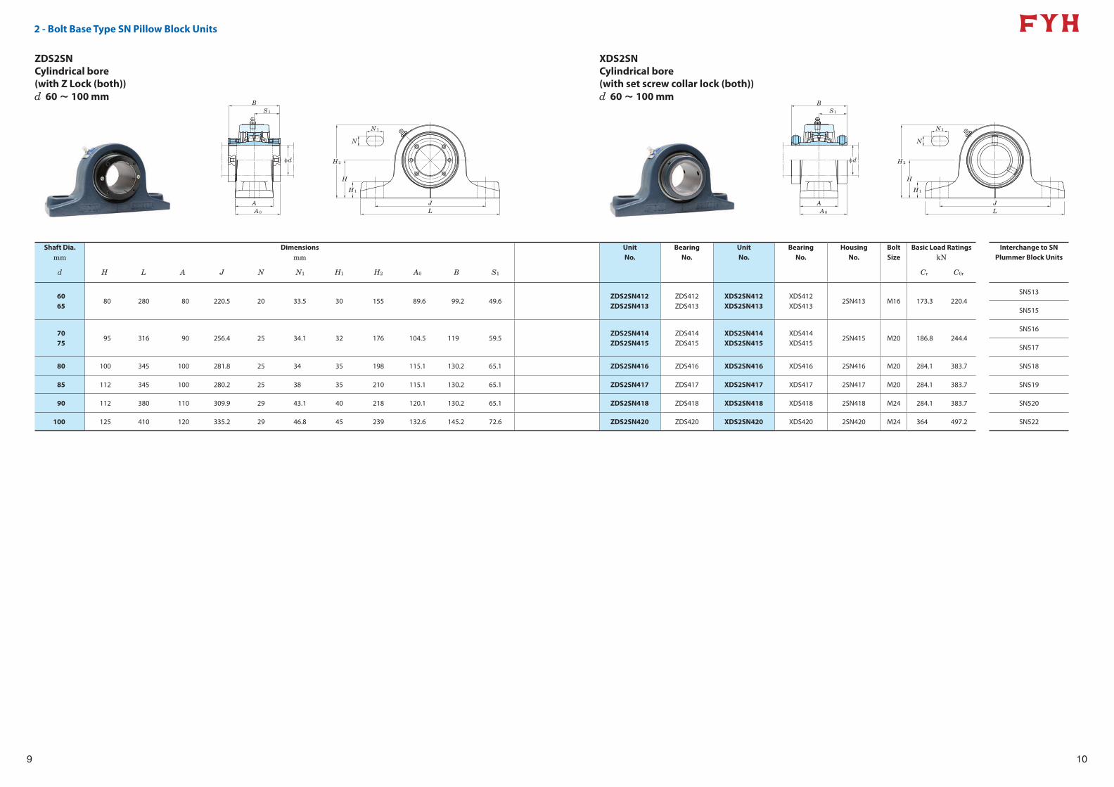
ZDS2SNCylindrical bore (with Z Lock (both))
XDS2SNCylindrical bore (with set screw collar lock (both))
Shaft Dia. Dimensions Unit Bearing Unit Bearing Housing Bolt Basic Load Ratings Interchange to SNmm mm No. No. No. No. No. Size kN Plummer Block Units
d H L A J N N1 H1 H2 A0 B S1 Cr C0r
6065
80 280 80 220.5 20 33.5 30 155 89.6 99.2 49.6ZDS2SN412ZDS2SN413
ZDS412ZDS413
XDS2SN412XDS2SN413
XDS412XDS413
2SN413 M16 173.3 220.4SN513
SN515
7075
95 316 90 256.4 25 34.1 32 176 104.5 119 59.5ZDS2SN414ZDS2SN415
ZDS414ZDS415
XDS2SN414XDS2SN415
XDS414XDS415
2SN415 M20 186.8 244.4SN516
SN517
80 100 345 100 281.8 25 34 35 198 115.1 130.2 65.1 ZDS2SN416 ZDS416 XDS2SN416 XDS416 2SN416 M20 284.1 383.7 SN518
85 112 345 100 280.2 25 38 35 210 115.1 130.2 65.1 ZDS2SN417 ZDS417 XDS2SN417 XDS417 2SN417 M20 284.1 383.7 SN519
90 112 380 110 309.9 29 43.1 40 218 120.1 130.2 65.1 ZDS2SN418 ZDS418 XDS2SN418 XDS418 2SN418 M24 284.1 383.7 SN520
100 125 410 120 335.2 29 46.8 45 239 132.6 145.2 72.6 ZDS2SN420 ZDS420 XDS2SN420 XDS420 2SN420 M24 364 497.2 SN522
d 60 ~ 100 mm d 60 ~ 100 mm
11
2 - Bolt Base Pillow Block Units
BS S1
φd
AA0
H2
HH1
JL
N
N1
12
BS S1
φd
AA0
H2
HH1
JL
N
N1
ZS2PCylindrical bore (with Z Lock)
XS2PCylindrical bore (with set screw collar lock)
Shaft Dia. Dimensions Unit Bearing Unit Bearing Housing Bolt Basic Load Ratingsinch inch No. No. No. No. No. Size kNmm mm
inchmmd H L A J N N1 H1 H2 A0 B S S1 Cr C0r
1 3/8
1 7/16
1 1/2
40
1 7/8
47.66 7/8
1752 5/32
555 9/32
134
19/32
151 3/32
281 1/4
323 25/32
962 5/8
66.42.53164.3
125.4
1.53138.9
ZS2P408-22ZS2P408-23ZS2P408-24ZS2P408
ZS408-22ZS408-23ZS408-24ZS408
XS2P408-22XS2P408-23XS2P408-24XS2P408
XS408-22XS408-23XS408-24XS408
2P4081/2
M1288.7 101.1
1 11/16
1 3/4
45
2 1/8
547 3/8
1872 3/8
605 25/32
147
19/32
151 3/32
281 5/16
334 1/4
1082 27/32
72.12.65767.5
125.4
1.65742.1
ZS2P409-27ZS2P409-28ZS2P409
ZS409-27ZS409-28ZS409
XS2P409-27XS2P409-28XS2P409
XS409-27XS409-28XS409
2P4091/2
M1292.6 108.8
1 15/16
502
2 1/4
57.28 3/8
2132 7/16
626 17/32
166
25/32
201 5/16
331 3/8
354 1/2
1143 1/16
77.82.84372.2
125.4
1.84346.8
ZS2P410-31ZS2P410ZS2P410-32
ZS410-31ZS410ZS410-32
XS2P410-31XS2P410XS2P410-32
XS410-31XS410XS410-32
2P4105/8
M1696.4 116.9
552 3/16
2 1/4
2 1/2
63.58 7/8
2252 5/8
676 7/8
175
25/32
201 3/16
301 5/8
414 31/32
1263 1/8
79.52.93774.6
1.12628.6
1.81146
ZS2P411ZS2P411-35ZS2P411-36
ZS411ZS411-35ZS411-36
XS2P411XS2P411-35XS2P411-36
XS411XS411-35XS411-36
2P4115/8
M16120.8 146.8
602 7/16
2 1/2
65
2 3/4
69.89 1/4
2352 7/8
737 9/32
185
25/32
201 3/16
301 25/32
455 19/32
1423 3/8
86.13.20581.4
1.25231.8
1.95349.6
ZS2P412ZS2P413-39ZS2P413-40ZS2P413
ZS412ZS413-39ZS413-40ZS413
XS2P412XS2P413-39XS2P413-40XS2P413
XS412XS413-39XS413-40XS413
2P4135/8
M16173.3 220.4
702 11/16
2 3/4
2 15/16
753
3 1/4
82.610 7/16
2653
768 9/32
210
15/16
241 9/32
321 7/8
486 3/8
1623 13/16
973.59491.3
1.25231.8
2.34359.5
ZS2P414ZS2P415-43ZS2P415-44ZS2P415-47ZS2P415ZS2P415-48
ZS414ZS415-43ZS415-44ZS415-47ZS415ZS415-48
XS2P414XS2P415-43XS2P415-44XS2P415-47XS2P415XS2P415-48
XS414XS415-43XS415-44XS415-47XS415XS415-48
2P4153/4
M20186.8 244.4
803 1/4
853 7/16
3 1/2
90
3 3/4
95.213
3303 3/8
8610 5/16
2621 1/16
271 23/32
442 1/4
577 15/32
1904 1/4
108.14.079103.6
1.51638.5
2.56365.1
ZS2P416ZS2P417-52ZS2P417ZS2P418-55ZS2P418-56ZS2P418
ZS416ZS417-52ZS417ZS418-55ZS418-56ZS418
XS2P416XS2P417-52XS2P417XS2P418-55XS2P418-56XS2P418
XS416XS417-52XS417XS418-55XS418-56XS418
2P4187/8
M22284.1 383.7
1003 15/16
4
4 1/4
10815 1/4
3873 3/4
9511 1/4
2861 5/32
292 5/16
592 17/32
648 11/32
2124 23/32
120.14.484113.9
1.62641.3
2.85872.6
ZS2P420ZS2P420-63ZS2P420-64
ZS420ZS420-63ZS420-64
XS2P420XS2P420-63XS2P420-64
XS420XS420-63XS420-64
2P4201
M24364 497.2
d 1 3/8 ~ 4 inch40 ~ 100 mm
d 1 3/8 ~ 4 inch40 ~ 100 mm
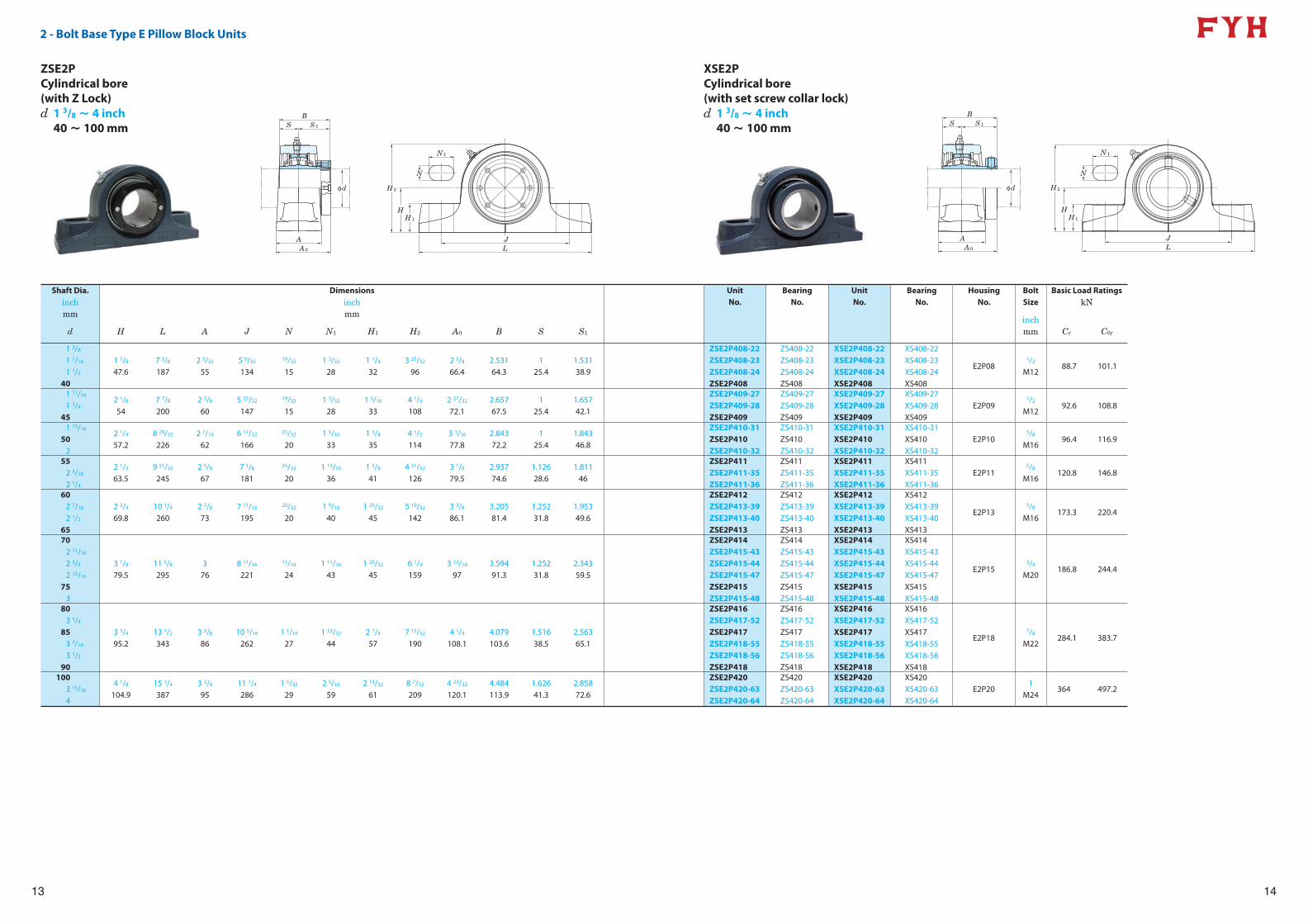
2 - Bolt Base Type E Pillow Block Units
BS S1
φd
AA0
H2
HH1
JL
N
N1
13
BS S1
φd
AA0
H2
HH1
JL
N
N1
14
ZSE2PCylindrical bore (with Z Lock)
XSE2PCylindrical bore (with set screw collar lock)
Shaft Dia. Dimensions Unit Bearing Unit Bearing Housing Bolt Basic Load Ratingsinch inch No. No. No. No. No. Size kNmm mm
inchmmd H L A J N N1 H1 H2 A0 B S S1 Cr C0r
1 3/8
1 7/16
1 1/2
40
1 7/8
47.67 3/8
1872 5/32
555 9/32
134
19/32
151 3/32
281 1/4
323 25/32
962 5/8
66.42.53164.3
125.4
1.53138.9
ZSE2P408-22ZSE2P408-23ZSE2P408-24ZSE2P408
ZS408-22ZS408-23ZS408-24ZS408
XSE2P408-22XSE2P408-23XSE2P408-24XSE2P408
XS408-22XS408-23XS408-24XS408
E2P081/2
M1288.7 101.1
1 11/16
1 3/4
45
2 1/8
547 7/8
2002 3/8
605 25/32
147
19/32
151 3/32
281 5/16
334 1/4
1082 27/32
72.12.65767.5
125.4
1.65742.1
ZSE2P409-27ZSE2P409-28ZSE2P409
ZS409-27ZS409-28ZS409
XSE2P409-27XSE2P409-28XSE2P409
XS409-27XS409-28XS409
E2P091/2
M1292.6 108.8
1 15/16
502
2 1/4
57.28 29/32
2262 7/16
626 17/32
166
25/32
201 5/16
331 3/8
354 1/2
1143 1/16
77.82.84372.2
125.4
1.84346.8
ZSE2P410-31ZSE2P410ZSE2P410-32
ZS410-31ZS410ZS410-32
XSE2P410-31XSE2P410XSE2P410-32
XS410-31XS410XS410-32
E2P105/8
M1696.4 116.9
552 3/16
2 1/4
2 1/2
63.59 21/32
2452 5/8
677 1/8
181
25/32
201 13/32
361 5/8
414 31/32
1263 1/8
79.52.93774.6
1.12628.6
1.81146
ZSE2P411ZSE2P411-35ZSE2P411-36
ZS411ZS411-35ZS411-36
XSE2P411XSE2P411-35XSE2P411-36
XS411XS411-35XS411-36
E2P115/8
M16120.8 146.8
602 7/16
2 1/2
65
2 3/4
69.810 1/4
2602 7/8
737 11/16
195
25/32
201 9/16
401 25/32
455 19/32
1423 3/8
86.13.20581.4
1.25231.8
1.95349.6
ZSE2P412ZSE2P413-39ZSE2P413-40ZSE2P413
ZS412ZS413-39ZS413-40ZS413
XSE2P412XSE2P413-39XSE2P413-40XSE2P413
XS412XS413-39XS413-40XS413
E2P135/8
M16173.3 220.4
702 11/16
2 3/4
2 15/16
753
3 1/8
79.511 5/8
2953
768 11/16
221
15/16
241 11/16
431 25/32
456 1/4
1593 13/16
973.59491.3
1.25231.8
2.34359.5
ZSE2P414ZSE2P415-43ZSE2P415-44ZSE2P415-47ZSE2P415ZSE2P415-48
ZS414ZS415-43ZS415-44ZS415-47ZS415ZS415-48
XSE2P414XSE2P415-43XSE2P415-44XSE2P415-47XSE2P415XSE2P415-48
XS414XS415-43XS415-44XS415-47XS415XS415-48
E2P153/4
M20186.8 244.4
803 1/4
853 7/16
3 1/2
90
3 3/4
95.213 1/2
3433 3/8
8610 5/16
2621 1/16
271 23/32
442 1/4
577 15/32
1904 1/4
108.14.079103.6
1.51638.5
2.56365.1
ZSE2P416ZSE2P417-52ZSE2P417ZSE2P418-55ZSE2P418-56ZSE2P418
ZS416ZS417-52ZS417ZS418-55ZS418-56ZS418
XSE2P416XSE2P417-52XSE2P417XSE2P418-55XSE2P418-56XSE2P418
XS416XS417-52XS417XS418-55XS418-56XS418
E2P187/8
M22284.1 383.7
1003 15/16
4
4 1/8
104.915 1/4
3873 3/4
9511 1/4
2861 5/32
292 5/16
592 13/32
618 7/32
2094 23/32
120.14.484113.9
1.62641.3
2.85872.6
ZSE2P420ZSE2P420-63ZSE2P420-64
ZS420ZS420-63ZS420-64
XSE2P420XSE2P420-63XSE2P420-64
XS420XS420-63XS420-64
E2P201
M24364 497.2
d 1 3/8 ~ 4 inch40 ~ 100 mm
d 1 3/8 ~ 4 inch40 ~ 100 mm
15
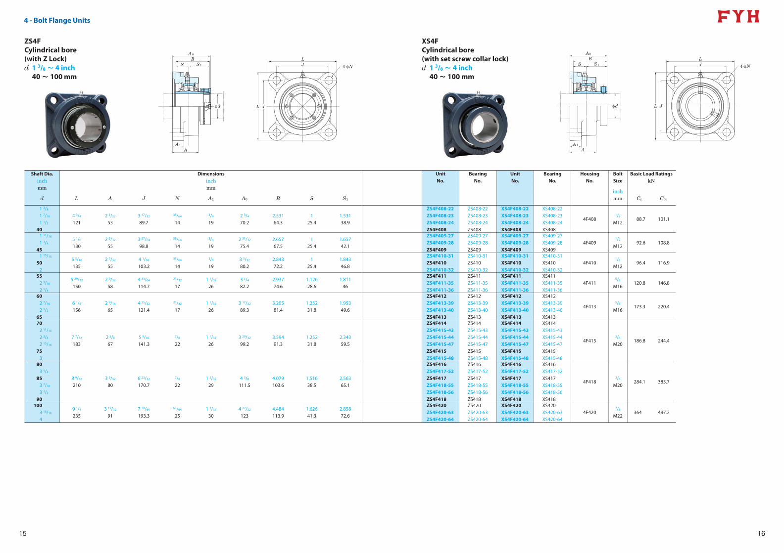
4 - Bolt Flange Units
4-φN
LJ
JL
A0
BS S1
A1
A
φd
16
A0
BS S1
A1
A
φd L J
LJ 4-φN
ZS4FCylindrical bore (with Z Lock)
XS4FCylindrical bore (with set screw collar lock)
Shaft Dia. Dimensions Unit Bearing Unit Bearing Housing Bolt Basic Load Ratingsinch inch No. No. No. No. No. Size kNmm mm
inchmmd L A J N A1 A0 B S S1 Cr C0r
1 3/8
1 7/16
1 1/2
40
4 3/4
1212 3/32
533 17/32
89.7
35/64
14
3/4
192 3/4
70.22.53164.3
125.4
1.53138.9
ZS4F408-22ZS4F408-23ZS4F408-24ZS4F408
ZS408-22ZS408-23ZS408-24ZS408
XS4F408-22XS4F408-23XS4F408-24XS4F408
XS408-22XS408-23XS408-24XS408
4F4081/2
M1288.7 101.1
1 11/16
1 3/4
45
5 1/8
1302 5/32
553 57/64
98.8
35/64
14
3/4
192 31/32
75.42.65767.5
125.4
1.65742.1
ZS4F409-27ZS4F409-28ZS4F409
ZS409-27ZS409-28ZS409
XS4F409-27XS4F409-28XS4F409
XS409-27XS409-28XS409
4F4091/2
M1292.6 108.8
1 15/16
502
5 5/16
1352 5/32
554 1/16
103.2
35/64
14
3/4
193 5/32
80.22.84372.2
125.4
1.84346.8
ZS4F410-31ZS4F410ZS4F410-32
ZS410-31ZS410ZS410-32
XS4F410-31XS4F410XS4F410-32
XS410-31XS410XS410-32
4F4101/2
M1296.4 116.9
552 3/16
2 1/4
5 29/32
1502 9/32
584 33/64
114.7
21/32
171 1/32
263 1/4
82.22.93774.6
1.12628.6
1.81146
ZS4F411ZS4F411-35ZS4F411-36
ZS411ZS411-35ZS411-36
XS4F411XS4F411-35XS4F411-36
XS411XS411-35XS411-36
4F4115/8
M16120.8 146.8
602 7/16
2 1/2
65
6 1/8
1562 9/16
654 25/32
121.4
21/32
171 1/32
263 17/32
89.33.20581.4
1.25231.8
1.95349.6
ZS4F412ZS4F413-39ZS4F413-40ZS4F413
ZS412ZS413-39ZS413-40ZS413
XS4F412XS4F413-39XS4F413-40XS4F413
XS412XS413-39XS413-40XS413
4F4135/8
M16173.3 220.4
702 11/16
2 3/4
2 15/16
753
7 7/32
1832 5/8
675 9/16
141.3
7/8
221 1/32
263 29/32
99.23.59491.3
1.25231.8
2.34359.5
ZS4F414ZS4F415-43ZS4F415-44ZS4F415-47ZS4F415ZS4F415-48
ZS414ZS415-43ZS415-44ZS415-47ZS415ZS415-48
XS4F414XS4F415-43XS4F415-44XS4F415-47XS4F415XS4F415-48
XS414XS415-43XS415-44XS415-47XS415XS415-48
4F4153/4
M20186.8 244.4
803 1/4
853 7/16
3 1/2
90
8 9/32
2103 5/32
806 23/32
170.7
7/8
221 5/32
294 3/8
111.54.079103.6
1.51638.5
2.56365.1
ZS4F416ZS4F417-52ZS4F417ZS4F418-55ZS4F418-56ZS4F418
ZS416ZS417-52ZS417ZS418-55ZS418-56ZS418
XS4F416XS4F417-52XS4F417XS4F418-55XS4F418-56XS4F418
XS416XS417-52XS417XS418-55XS418-56XS418
4F4183/4
M20284.1 383.7
1003 15/16
4
9 1/4
2353 19/32
917 39/64
193.3
63/64
251 3/16
304 27/32
1234.484113.9
1.62641.3
2.85872.6
ZS4F420ZS4F420-63ZS4F420-64
ZS420ZS420-63ZS420-64
XS4F420XS4F420-63XS4F420-64
XS420XS420-63XS420-64
4F4207/8
M22364 497.2
d 1 3/8 ~ 4 inch40 ~ 100 mm
d 1 3/8 ~ 4 inch40 ~ 100 mm
17
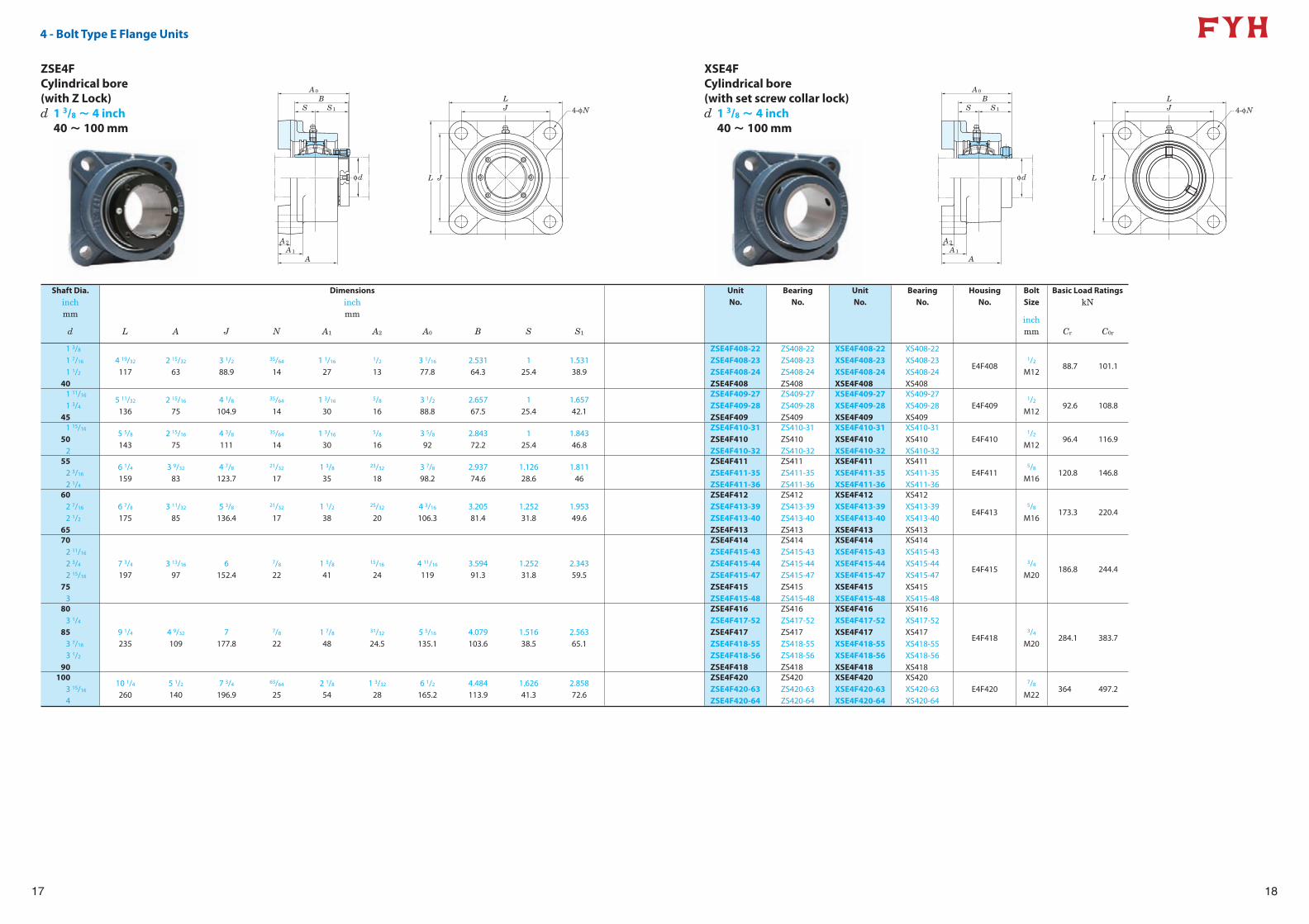
4 - Bolt Type E Flange Units
4-φN
A0
BS S1
A1
A2
A
φd L J
LJ
18
4-φN
A0
BS S1
A1
A2
A
φd L J
LJ
ZSE4FCylindrical bore (with Z Lock)
XSE4FCylindrical bore (with set screw collar lock)
Shaft Dia. Dimensions Unit Bearing Unit Bearing Housing Bolt Basic Load Ratingsinch inch No. No. No. No. No. Size kNmm mm
inchmmd L A J N A1 A2 A0 B S S1 Cr C0r
1 3/8
1 7/16
1 1/2
40
4 19/32
1172 15/32
633 1/2
88.9
35/64
141 1/16
27
1/2
133 1/16
77.82.53164.3
125.4
1.53138.9
ZSE4F408-22ZSE4F408-23ZSE4F408-24ZSE4F408
ZS408-22ZS408-23ZS408-24ZS408
XSE4F408-22XSE4F408-23XSE4F408-24XSE4F408
XS408-22XS408-23XS408-24XS408
E4F4081/2
M1288.7 101.1
1 11/16
1 3/4
45
5 11/32
1362 15/16
754 1/8
104.9
35/64
141 3/16
30
5/8
163 1/2
88.82.65767.5
125.4
1.65742.1
ZSE4F409-27ZSE4F409-28ZSE4F409
ZS409-27ZS409-28ZS409
XSE4F409-27XSE4F409-28XSE4F409
XS409-27XS409-28XS409
E4F4091/2
M1292.6 108.8
1 15/16
502
5 5/8
1432 15/16
754 3/8
111
35/64
141 3/16
30
5/8
163 5/8
922.84372.2
125.4
1.84346.8
ZSE4F410-31ZSE4F410ZSE4F410-32
ZS410-31ZS410ZS410-32
XSE4F410-31XSE4F410XSE4F410-32
XS410-31XS410XS410-32
E4F4101/2
M1296.4 116.9
552 3/16
2 1/4
6 1/4
1593 9/32
834 7/8
123.7
21/32
171 3/8
35
23/32
183 7/8
98.22.93774.6
1.12628.6
1.81146
ZSE4F411ZSE4F411-35ZSE4F411-36
ZS411ZS411-35ZS411-36
XSE4F411XSE4F411-35XSE4F411-36
XS411XS411-35XS411-36
E4F4115/8
M16120.8 146.8
602 7/16
2 1/2
65
6 7/8
1753 11/32
855 3/8
136.4
21/32
171 1/2
38
25/32
204 3/16
106.33.20581.4
1.25231.8
1.95349.6
ZSE4F412ZSE4F413-39ZSE4F413-40ZSE4F413
ZS412ZS413-39ZS413-40ZS413
XSE4F412XSE4F413-39XSE4F413-40XSE4F413
XS412XS413-39XS413-40XS413
E4F4135/8
M16173.3 220.4
702 11/16
2 3/4
2 15/16
753
7 3/4
1973 13/16
976
152.4
7/8
221 5/8
41
15/16
244 11/16
1193.59491.3
1.25231.8
2.34359.5
ZSE4F414ZSE4F415-43ZSE4F415-44ZSE4F415-47ZSE4F415ZSE4F415-48
ZS414ZS415-43ZS415-44ZS415-47ZS415ZS415-48
XSE4F414XSE4F415-43XSE4F415-44XSE4F415-47XSE4F415XSE4F415-48
XS414XS415-43XS415-44XS415-47XS415XS415-48
E4F4153/4
M20186.8 244.4
803 1/4
853 7/16
3 1/2
90
9 1/4
2354 9/32
1097
177.8
7/8
221 7/8
48
31/32
24.55 5/16
135.14.079103.6
1.51638.5
2.56365.1
ZSE4F416ZSE4F417-52ZSE4F417ZSE4F418-55ZSE4F418-56ZSE4F418
ZS416ZS417-52ZS417ZS418-55ZS418-56ZS418
XSE4F416XSE4F417-52XSE4F417XSE4F418-55XSE4F418-56XSE4F418
XS416XS417-52XS417XS418-55XS418-56XS418
E4F4183/4
M20284.1 383.7
1003 15/16
4
10 1/4
2605 1/2
1407 3/4
196.9
63/64
252 1/8
541 3/32
286 1/2
165.24.484113.9
1.62641.3
2.85872.6
ZSE4F420ZSE4F420-63ZSE4F420-64
ZS420ZS420-63ZS420-64
XSE4F420XSE4F420-63XSE4F420-64
XS420XS420-63XS420-64
E4F4207/8
M22364 497.2
d 1 3/8 ~ 4 inch40 ~ 100 mm
d 1 3/8 ~ 4 inch40 ~ 100 mm
19
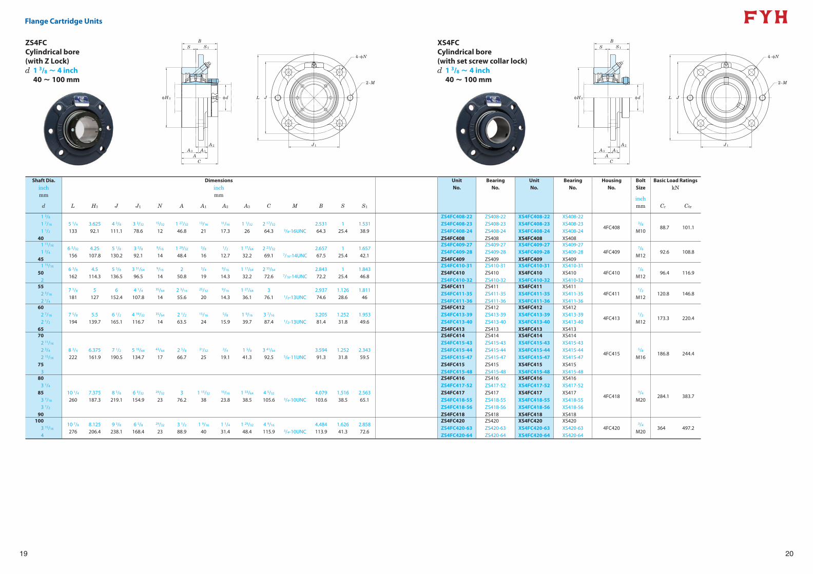
Flange Cartridge Units
BS S1
φH3 φd
A3
A2
A1
AC
L J
J1
4-φN
2-M
20
BS S1
φH3 φd
A3
A2
A1
AC
L J
J1
4-φN
2-M
ZS4FCCylindrical bore (with Z Lock)
XS4FCCylindrical bore (with set screw collar lock)
Shaft Dia. Dimensions Unit Bearing Unit Bearing Housing Bolt Basic Load Ratingsinch inch No. No. No. No. No. Size kNmm mm
inchmmd L H3 J J1 N A A1 A2 A3 C M B S S1 Cr C0r
1 3/8
1 7/16
1 1/2
40
5 1/4
1333.62592.1
4 3/8
111.13 3/32
78.6
15/32
121 27/32
46.8
13/16
21
11/16
17.31 1/32
262 17/32
64.3 3/8-16UNC2.53164.3
125.4
1.53138.9
ZS4FC408-22ZS4FC408-23ZS4FC408-24ZS4FC408
ZS408-22ZS408-23ZS408-24ZS408
XS4FC408-22XS4FC408-23XS4FC408-24XS4FC408
XS408-22XS408-23XS408-24XS408
4FC4083/8
M1088.7 101.1
1 11/16
1 3/4
45
6 5/32
1564.25
107.85 1/8
130.23 5/8
92.1
9/16
141 29/32
48.4
5/8
16
1/2
12.71 17/64
32.22 23/32
69.1 7/16-14UNC2.65767.5
125.4
1.65742.1
ZS4FC409-27ZS4FC409-28ZS4FC409
ZS409-27ZS409-28ZS409
XS4FC409-27XS4FC409-28XS4FC409
XS409-27XS409-28XS409
4FC4097/6
M1292.6 108.8
1 15/16
502
6 3/8
1624.5
114.35 3/8
136.53 51/64
96.5
9/16
142
50.8
3/4
19
9/16
14.31 17/64
32.22 55/64
72.6 7/16-14UNC2.84372.2
125.4
1.84346.8
ZS4FC410-31ZS4FC410ZS4FC410-32
ZS410-31ZS410ZS410-32
XS4FC410-31XS4FC410XS4FC410-32
XS410-31XS410XS410-32
4FC4107/6
M1296.4 116.9
552 3/16
2 1/4
7 1/8
1815
1276
152.44 1/4
107.8
35/64
142 3/16
55.6
25/32
20
9/16
14.31 27/64
36.13
76.1 1/2-13UNC2.93774.6
1.12628.6
1.81146
ZS4FC411ZS4FC411-35ZS4FC411-36
ZS411ZS411-35ZS411-36
XS4FC411XS4FC411-35XS4FC411-36
XS411XS411-35XS411-36
4FC4111/2
M12120.8 146.8
602 7/16
2 1/2
65
7 5/8
1945.5
139.76 1/2
165.14 19/32
116.7
35/64
142 1/2
63.5
15/16
24
5/8
15.91 9/16
39.73 7/16
87.4 1/2-13UNC3.20581.4
1.25231.8
1.95349.6
ZS4FC412ZS4FC413-39ZS4FC413-40ZS4FC413
ZS412ZS413-39ZS413-40ZS413
XS4FC412XS4FC413-39XS4FC413-40XS4FC413
XS412XS413-39XS413-40XS413
4FC4131/2
M12173.3 220.4
702 11/16
2 3/4
2 15/16
753
8 3/4
2226.375161.9
7 1/2
190.55 19/64
134.7
43/64
172 5/8
66.7
31/32
25
3/4
19.11 5/8
41.33 41/64
92.5 5/8-11UNC3.59491.3
1.25231.8
2.34359.5
ZS4FC414ZS4FC415-43ZS4FC415-44ZS4FC415-47ZS4FC415ZS4FC415-48
ZS414ZS415-43ZS415-44ZS415-47ZS415ZS415-48
XS4FC414XS4FC415-43XS4FC415-44XS4FC415-47XS4FC415XS4FC415-48
XS414XS415-43XS415-44XS415-47XS415XS415-48
4FC4155/8
M16186.8 244.4
803 1/4
853 7/16
3 1/2
90
10 1/4
2607.375187.3
8 5/8
219.16 3/32
154.9
29/32
233
76.21 15/32
38
15/16
23.81 33/64
38.54 5/32
105.6 3/4-10UNC4.079103.6
1.51638.5
2.56365.1
ZS4FC416ZS4FC417-52ZS4FC417ZS4FC418-55ZS4FC418-56ZS4FC418
ZS416ZS417-52ZS417ZS418-55ZS418-56ZS418
XS4FC416XS4FC417-52XS4FC417XS4FC418-55XS4FC418-56XS4FC418
XS416XS417-52XS417XS418-55XS418-56XS418
4FC4183/4
M20284.1 383.7
1003 15/16
4
10 7/8
2768.125206.4
9 3/8
238.16 5/8
168.4
29/32
233 1/2
88.91 9/16
401 1/4
31.41 29/32
48.44 9/16
115.9 3/4-10UNC4.484113.9
1.62641.3
2.85872.6
ZS4FC420ZS4FC420-63ZS4FC420-64
ZS420ZS420-63ZS420-64
XS4FC420XS4FC420-63XS4FC420-64
XS420XS420-63XS420-64
4FC4203/4
M20364 497.2
d 1 3/8 ~ 4 inch40 ~ 100 mm
d 1 3/8 ~ 4 inch40 ~ 100 mm
21
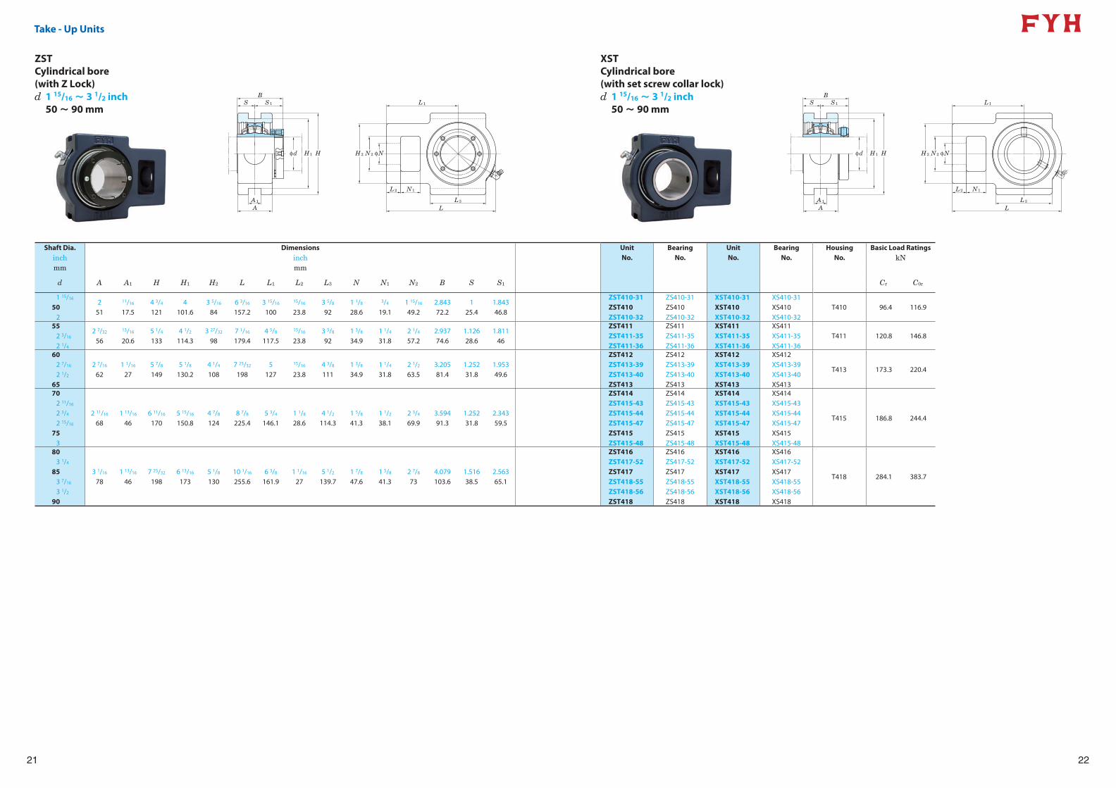
Take - Up Units
BS S1
φd H1 H
A1
A
H2 N2 φN
L1
L3
L
N1L2
22
BS S1
φd H1 H
A1
A
H2 N2 φN
L1
L3
L
N1L2
ZSTCylindrical bore (with Z Lock)
XSTCylindrical bore (with set screw collar lock)
Shaft Dia. Dimensions Unit Bearing Unit Bearing Housing Basic Load Ratingsinch inch No. No. No. No. No. kNmm mm
d A A1 H H1 H2 L L1 L2 L3 N N1 N2 B S S1 Cr C0r
1 15/16
502
251
11/16
17.54 3/4
1214
101.63 5/16
846 3/16
157.23 15/16
100
15/16
23.83 5/8
921 1/8
28.6
3/4
19.11 15/16
49.22.84372.2
125.4
1.84346.8
ZST410-31ZST410ZST410-32
ZS410-31ZS410ZS410-32
XST410-31XST410XST410-32
XS410-31XS410XS410-32
T410 96.4 116.9
552 3/16
2 1/4
2 7/32
56
13/16
20.65 1/4
1334 1/2
114.33 27/32
987 1/16
179.44 5/8
117.5
15/16
23.83 5/8
921 3/8
34.91 1/4
31.82 1/4
57.22.93774.6
1.12628.6
1.81146
ZST411ZST411-35ZST411-36
ZS411ZS411-35ZS411-36
XST411XST411-35XST411-36
XS411XS411-35XS411-36
T411 120.8 146.8
602 7/16
2 1/2
65
2 7/16
621 1/16
275 7/8
1495 1/8
130.24 1/4
1087 25/32
1985
127
15/16
23.84 3/8
1111 3/8
34.91 1/4
31.82 1/2
63.53.20581.4
1.25231.8
1.95349.6
ZST412ZST413-39ZST413-40ZST413
ZS412ZS413-39ZS413-40ZS413
XST412XST413-39XST413-40XST413
XS412XS413-39XS413-40XS413
T413 173.3 220.4
702 11/16
2 3/4
2 15/16
753
2 11/16
681 13/16
466 11/16
1705 15/16
150.84 7/8
1248 7/8
225.45 3/4
146.11 1/8
28.64 1/2
114.31 5/8
41.31 1/2
38.12 3/4
69.93.59491.3
1.25231.8
2.34359.5
ZST414ZST415-43ZST415-44ZST415-47ZST415ZST415-48
ZS414ZS415-43ZS415-44ZS415-47ZS415ZS415-48
XST414XST415-43XST415-44XST415-47XST415XST415-48
XS414XS415-43XS415-44XS415-47XS415XS415-48
T415 186.8 244.4
803 1/4
853 7/16
3 1/2
90
3 1/16
781 13/16
467 25/32
1986 13/16
1735 1/8
13010 1/16
255.66 3/8
161.91 1/16
275 1/2
139.71 7/8
47.61 5/8
41.32 7/8
734.079103.6
1.51638.5
2.56365.1
ZST416ZST417-52ZST417ZST418-55ZST418-56ZST418
ZS416ZS417-52ZS417ZS418-55ZS418-56ZS418
XST416XST417-52XST417XST418-55XST418-56XST418
XS416XS417-52XS417XS418-55XS418-56XS418
T418 284.1 383.7
d 1 15/16 ~ 3 1/2 inch50 ~ 90 mm
d 1 15/16 ~ 3 1/2 inch50 ~ 90 mm
23
4 - Bolt Base Pillow Block Units
BS1
H
H2
AA0 L
J
H1
N
N
N1
E
N1
S
φd
24
BS1
H
H2
AA0 L
J
H1
N
N
N1
E
N1
S
φd
ZS4PCylindrical bore (with Z Lock)
XS4PCylindrical bore (with set screw collar lock)
Shaft Dia. Dimensions Unit Bearing Unit Bearing Housing Bolt Basic Load Ratingsinch inch No. No. No. No. No. Size kNmm mm
inchmmd H L A J N N1 E H1 H2 A0 B S S1 Cr C0r
602 7/16
2 1/2
65
2 3/4
69.89 1/4
2353 3/8
867 1/8
181
19/32
15
13/16
211 3/4
441 5/8
415 19/32
1423 21/32
92.63.20581.4
1.25231.8
1.95349.6
ZS4P412ZS4P413-39ZS4P413-40ZS4P413
ZS412ZS413-39ZS413-40ZS413
XS4P412XS4P413-39XS4P413-40XS4P413
XS412XS413-39XS413-40XS413
4P4131/2
M12173.3 220.4
702 11/16
2 3/4
2 15/16
753
3 1/4
82.610 7/16
2653 3/4
958 1/8
206
25/32
20
15/16
241 7/8
481 7/8
486 3/8
1624 7/32
1073.59491.3
1.25231.8
2.34359.5
ZS4P414ZS4P415-43ZS4P415-44ZS4P415-47ZS4P415ZS4P415-48
ZS414ZS415-43ZS415-44ZS415-47ZS415ZS415-48
XS4P414XS4P415-43XS4P415-44XS4P415-47XS4P415XS4P415-48
XS414XS415-43XS415-44XS415-47XS415XS415-48
4P4155/8
M16186.8 244.4
803 1/4
853 7/16
3 1/2
90
3 3/4
95.213
3304 1/8
10510
254
15/16
241 1/2
382
50.82 1/4
577 9/16
1924 5/8
117.64.079103.6
1.51638.5
2.56365.1
ZS4P416ZS4P417-52ZS4P417ZS4P418-55ZS4P418-56ZS4P418
ZS416ZS417-52ZS417ZS418-55ZS418-56ZS418
XS4P416XS4P417-52XS4P417XS4P418-55XS4P418-56XS4P418
XS416XS417-52XS417XS418-55XS418-56XS418
4P4183/4
M20284.1 383.7
1003 15/16
4
4 1/4
10815 1/4
3874 1/2
11412 1/2
318
15/16
241 17/32
392 1/4
572 7/16
628 3/8
2135 3/32
129.64.484113.9
1.62641.3
2.85872.6
ZS4P420ZS4P420-63ZS4P420-64
ZS420ZS420-63ZS420-64
XS4P420XS4P420-63XS4P420-64
XS420XS420-63XS420-64
4P4203/4
M20364 497.2
d 2 7/16 ~ 4 inch60 ~ 100 mm
d 2 7/16 ~ 4 inch60 ~ 100 mm
25
4 - Bolt Base Pillow Block Units
S1
B
H
H2
AA0 L
J
H1
N1
E
N1
N
N
φd
26
S1
B
H
H2
AA0 L
J
H1
N1
E
N1
N
N
φd
ZDS4PCylindrical bore (with Z Lock)
XDS4PCylindrical bore (with set screw collar lock)
Shaft Dia. Dimensions Unit Bearing Unit Bearing Housing Bolt Basic Load Ratingsinch inch No. No. No. No. No. Size kNmm mm
inchmmd H L A J N N1 E H1 H2 A0 B S1 Cr C0r
602 7/16
2 1/2
65
2 3/4
69.89 1/4
2353 3/8
867 1/8
181
19/32
15
13/16
211 3/4
441 5/8
415 19/32
1423 21/32
92.63.90699.2
1.95349.6
ZDS4P412ZDS4P413-39ZDS4P413-40ZDS4P413
ZDS412ZDS413-39ZDS413-40ZDS413
XDS4P412XDS4P413-39XDS4P413-40XDS4P413
XDS412XDS413-39XDS413-40XDS413
4P4131/2
M12173.3 220.4
702 11/16
2 3/4
2 15/16
753
3 1/4
82.610 7/16
2653 3/4
958 1/8
206
25/32
20
15/16
241 7/8
481 7/8
486 3/8
1624 7/32
1074.686119
2.34359.5
ZDS4P414ZDS4P415-43ZDS4P415-44ZDS4P415-47ZDS4P415ZDS4P415-48
ZDS414ZDS415-43ZDS415-44ZDS415-47ZDS415ZDS415-48
XDS4P414XDS4P415-43XDS4P415-44XDS4P415-47XDS4P415XDS4P415-48
XDS414XDS415-43XDS415-44XDS415-47XDS415XDS415-48
4P4155/8
M16186.8 244.4
803 1/4
853 7/16
3 1/2
90
3 3/4
95.213
3304 1/8
10510
254
15/16
241 1/2
382
50.82 1/4
577 9/16
1924 5/8
117.65.126130.2
2.56365.1
ZDS4P416ZDS4P417-52ZDS4P417ZDS4P418-55ZDS4P418-56ZDS4P418
ZDS416ZDS417-52ZDS417ZDS418-55ZDS418-56ZDS418
XDS4P416XDS4P417-52XDS4P417XDS4P418-55XDS4P418-56XDS4P418
XDS416XDS417-52XDS417XDS418-55XDS418-56XDS418
4P4183/4
M20284.1 383.7
1003 15/16
4
4 1/4
10815 1/4
3874 1/2
11412 1/2
318
15/16
241 17/32
392 1/4
572 7/16
628 3/8
2135 3/32
129.65.716145.2
2.85872.6
ZDS4P420ZDS4P420-63ZDS4P420-64
ZDS420ZDS420-63ZDS420-64
XDS4P420XDS4P420-63XDS4P420-64
XDS420XDS420-63XDS420-64
4P4203/4
M20364 497.2
d 2 7/16 ~ 4 inch60 ~ 100 mm
d 2 7/16 ~ 4 inch60 ~ 100 mm
27
Spherical Roller Bearing Inserts
28
B1
CB1
C
S S3S S3
φdφDφdφD
B1
C
S S3
φdφD
B1
C
S S3
φdφD
Shaft Dia. Dimensions Bearing Bearing Basic Load Ratingsinch inch No. No. kNmm mm
d C D B1 S S3 Cr C0r
1 3/8
1 7/16
1 1/2
40
15/16
243 5/32
802.53164.3
125.4
1.53138.9
ZS408-22ZS408-23ZS408-24ZS408
XS408-22XS408-23XS408-24XS408
88.7 101.1
1 11/16
1 3/4
45
15/16
243 11/32
852.65767.5
125.4
1.65742.1
ZS409-27ZS409-28ZS409
XS409-27XS409-28XS409
92.6 108.8
1 15/16
502
15/16
243 17/32
902.84372.2
125.4
1.84346.8
ZS410-31ZS410ZS410-32
XS410-31XS410XS410-32
96.4 116.9
552 3/16
2 1/4
1 1/32
263 15/16
1002.93774.6
1.12628.6
1.81146
ZS411ZS411-35ZS411-36
XS411XS411-35XS411-36
120.8 146.8
602 7/16
2 1/2
65
1 1/4
324 23/32
1203.20581.4
1.25231.8
1.95349.6
ZS412ZS413-39ZS413-40ZS413
XS412XS413-39XS413-40XS413
173.3 220.4
702 11/16
2 3/4
2 15/16
753
1 1/4
325 1/8
1303.59491.3
1.25231.8
2.34359.5
ZS414ZS415-43ZS415-44ZS415-47ZS415ZS415-48
XS414XS415-43XS415-44XS415-47XS415XS415-48
186.8 244.4
803 1/4
853 7/16
3 1/2
90
1 5/8
416 5/16
1604.079103.6
1.51638.5
2.56365.1
ZS416ZS417-52ZS417ZS418-55ZS418-56ZS418
XS416XS417-52XS417XS418-55XS418-56XS418
284.1 383.7
1003 15/16
4
1 27/32
477 3/32
1804.484113.9
1.62641.3
2.85872.6
ZS420ZS420-63ZS420-64
XS420XS420-63XS420-64
364 497.2
d 1 3/8 ~ 4 inch40 ~ 100 mm
d 2 7/16 ~ 4 inch60 ~ 100 mm
Shaft Dia. Dimensions Bearing Bearing Basic Load Ratingsinch inch No. No. kNmm mm
d C D B1 S S3 Cr C0r
602 7/16
2 1/2
65
1 1/4
324 23/32
1203.90599.2
1.95349.6
1.95349.6
ZDS412ZDS413-39ZDS413-40ZDS413
XDS412XDS413-39XDS413-40XDS413
173.3 220.4
702 11/16
2 3/4
2 15/16
753
1 1/4
325 1/8
1304.685119
2.34359.5
2.34359.5
ZDS414ZDS415-43ZDS415-44ZDS415-47ZDS415ZDS415-48
XDS414XDS415-43XDS415-44XDS415-47XDS415XDS415-48
186.8 244.4
803 1/4
853 7/16
3 1/2
90
1 5/8
416 5/16
1605.126130.2
2.56365.1
2.56365.1
ZDS416ZDS417-52ZDS417ZDS418-55ZDS418-56ZDS418
XDS416XDS417-52XDS417XDS418-55XDS418-56XDS418
284.1 383.7
1003 15/16
4
1 27/32
477 3/32
1805.716145.2
2.85872.6
2.85872.6
ZDS420ZDS420-63ZDS420-64
XDS420XDS420-63XDS420-64
364 497.2
XS4Cylindrical bore (with set screw collar lock)
XDS4Cylindrical bore (with set screw collar lock (both))
ZS4Cylindrical bore (with Z Lock)
ZDS4Cylindrical bore (with Z Lock (both))
29 30
FYH Spherical Roller Bearing Units Installation Guide
http://www.fyhbearings.com/html/tech_info.html#rollerhttp://www.fyhbearings.com/html/tech_info.html#roller
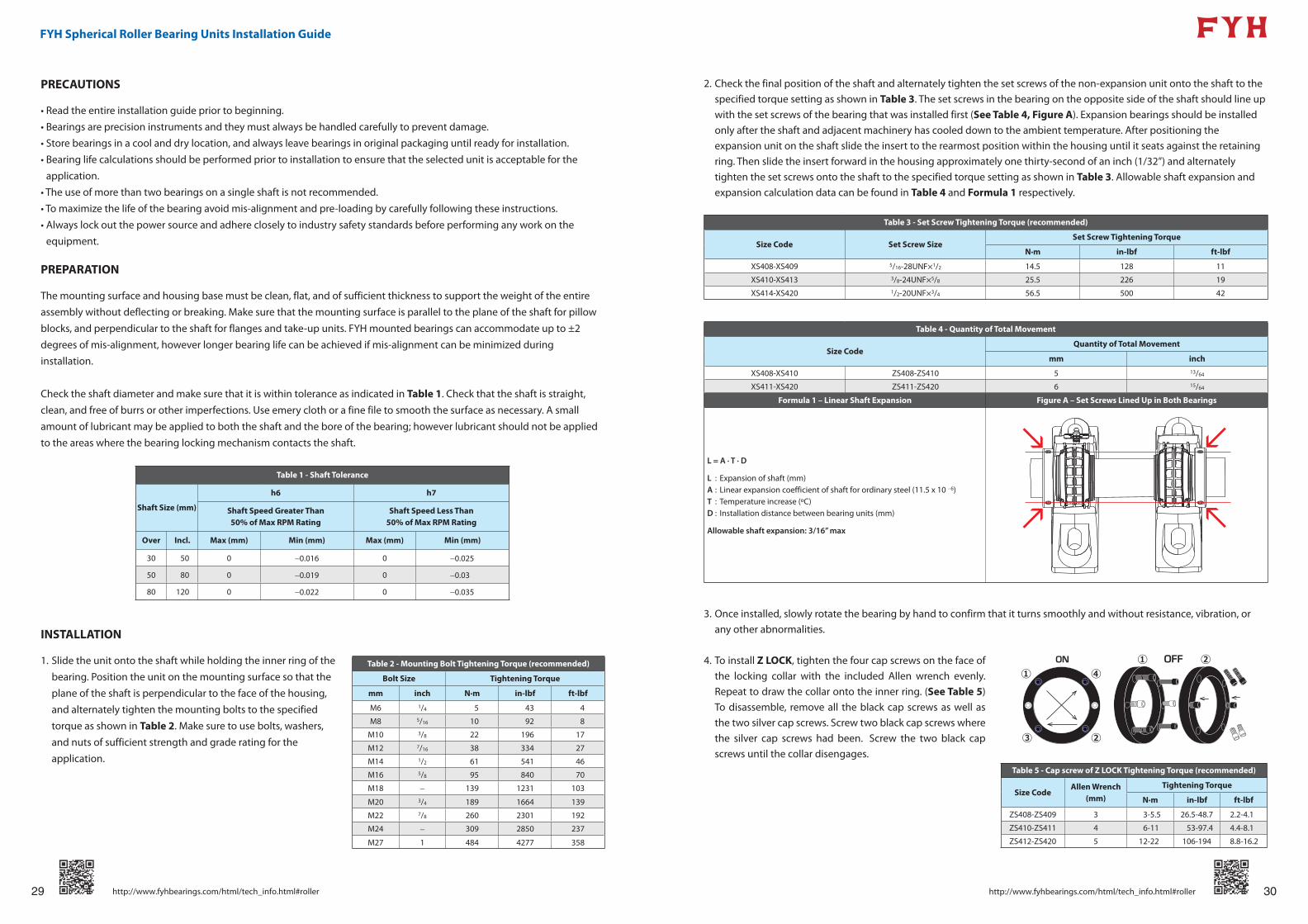
2. Check the final position of the shaft and alternately tighten the set screws of the non-expansion unit onto the shaft to the
specified torque setting as shown in Table 3. The set screws in the bearing on the opposite side of the shaft should line up
with the set screws of the bearing that was installed first (See Table 4, Figure A). Expansion bearings should be installed
only after the shaft and adjacent machinery has cooled down to the ambient temperature. After positioning the
expansion unit on the shaft slide the insert to the rearmost position within the housing until it seats against the retaining
ring. Then slide the insert forward in the housing approximately one thirty-second of an inch (1/32”) and alternately
tighten the set screws onto the shaft to the specified torque setting as shown in Table 3. Allowable shaft expansion and
expansion calculation data can be found in Table 4 and Formula 1 respectively.
Table 3 - Set Screw Tightening Torque (recommended)
Size Code Set Screw SizeSet Screw Tightening Torque
N·m in-lbf ft-lbf
XS408-XS409 5/16-28UNF×1/2 14.5 128 11
XS410-XS413 3/8-24UNF×5/8 25.5 226 19
XS414-XS420 1/2-20UNF×3/4 56.5 500 42
Table 4 - Quantity of Total Movement
Size CodeQuantity of Total Movement
mm inch
XS408-XS410 ZS408-ZS410 5 13/64
XS411-XS420 ZS411-ZS420 6 15/64
Formula 1 – Linear Shaft Expansion Figure A – Set Screws Lined Up in Both Bearings
L = A · T · D
L : Expansion of shaft (mm)A : Linear expansion coefficient of shaft for ordinary steel (11.5 x 10 −6)T : Temperature increase (ºC)D : Installation distance between bearing units (mm)
Allowable shaft expansion: 3/16” max
3. Once installed, slowly rotate the bearing by hand to confirm that it turns smoothly and without resistance, vibration, or
any other abnormalities.
4. To install Z LOCK, tighten the four cap screws on the face of
the locking collar with the included Allen wrench evenly.
Repeat to draw the collar onto the inner ring. (See Table 5)
To disassemble, remove all the black cap screws as well as
the two silver cap screws. Screw two black cap screws where
the silver cap screws had been. Screw the two black cap
screws until the collar disengages.
PRECAUTIONS
• Read the entire installation guide prior to beginning.
• Bearings are precision instruments and they must always be handled carefully to prevent damage.
• Store bearings in a cool and dry location, and always leave bearings in original packaging until ready for installation.
• Bearing life calculations should be performed prior to installation to ensure that the selected unit is acceptable for the
application.
• The use of more than two bearings on a single shaft is not recommended.
• To maximize the life of the bearing avoid mis-alignment and pre-loading by carefully following these instructions.
• Always lock out the power source and adhere closely to industry safety standards before performing any work on the
equipment.
PREPARATION
The mounting surface and housing base must be clean, flat, and of sufficient thickness to support the weight of the entire
assembly without deflecting or breaking. Make sure that the mounting surface is parallel to the plane of the shaft for pillow
blocks, and perpendicular to the shaft for flanges and take-up units. FYH mounted bearings can accommodate up to ±2
degrees of mis-alignment, however longer bearing life can be achieved if mis-alignment can be minimized during
installation.
Check the shaft diameter and make sure that it is within tolerance as indicated in Table 1. Check that the shaft is straight,
clean, and free of burrs or other imperfections. Use emery cloth or a fine file to smooth the surface as necessary. A small
amount of lubricant may be applied to both the shaft and the bore of the bearing; however lubricant should not be applied
to the areas where the bearing locking mechanism contacts the shaft.
Table 1 - Shaft Tolerance
Shaft Size (mm)
h6 h7
Shaft Speed Greater Than50% of Max RPM Rating
Shaft Speed Less Than50% of Max RPM Rating
Over Incl. Max (mm) Min (mm) Max (mm) Min (mm)
30 50 0 −0.016 0 −0.025
50 80 0 −0.019 0 −0.03
80 120 0 −0.022 0 −0.035
INSTALLATION
1. Slide the unit onto the shaft while holding the inner ring of the
bearing. Position the unit on the mounting surface so that the
plane of the shaft is perpendicular to the face of the housing,
and alternately tighten the mounting bolts to the specified
torque as shown in Table 2. Make sure to use bolts, washers,
and nuts of sufficient strength and grade rating for the
application.
Table 2 - Mounting Bolt Tightening Torque (recommended)
Bolt Size Tightening Torque
mm inch N·m in-lbf ft-lbf
M6 1/4 5 43 4
M8 5/16 10 92 8
M10 3/8 22 196 17
M12 7/16 38 334 27
M14 1/2 61 541 46
M16 5/8 95 840 70
M18 − 139 1231 103
M20 3/4 189 1664 139
M22 7/8 260 2301 192
M24 − 309 2850 237
M27 1 484 4277 358
Table 5 - Cap screw of Z LOCK Tightening Torque (recommended)
Size CodeAllen Wrench
(mm)
Tightening Torque
N·m in-lbf ft-lbf
ZS408-ZS409 3 3-5.5 26.5-48.7 2.2-4.1
ZS410-ZS411 4 6-11 53-97.4 4.4-8.1
ZS412-ZS420 5 12-22 106-194 8.8-16.2
31 32
FYH Spherical Roller Bearing Units Installation Guide
http://www.fyhbearings.com/html/tech_info.html#rollerhttp://www.fyhbearings.com/html/tech_info.html#roller
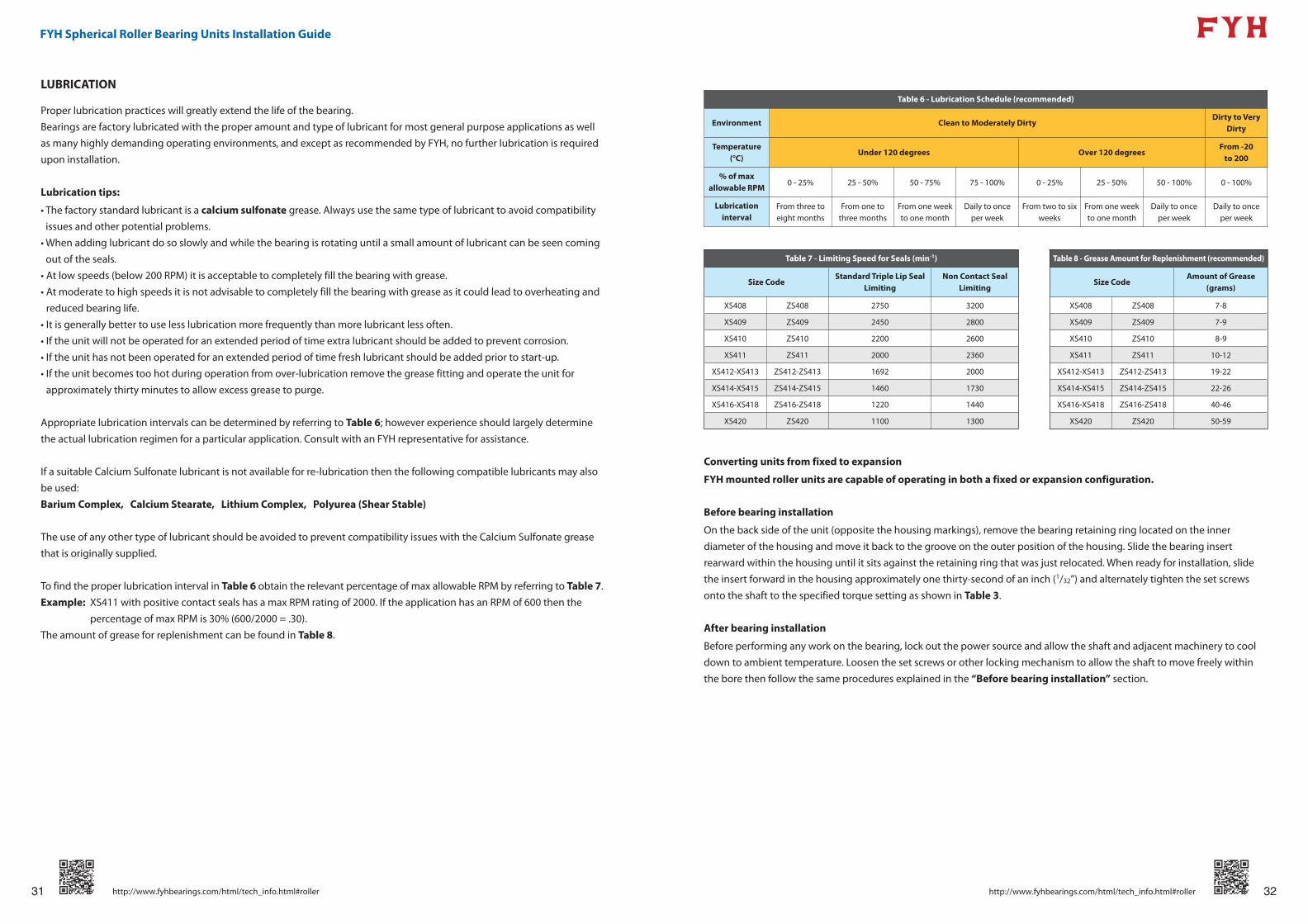
LUBRICATION
Proper lubrication practices will greatly extend the life of the bearing.
Bearings are factory lubricated with the proper amount and type of lubricant for most general purpose applications as well
as many highly demanding operating environments, and except as recommended by FYH, no further lubrication is required
upon installation.
Lubrication tips:
• The factory standard lubricant is a calcium sulfonate grease. Always use the same type of lubricant to avoid compatibility
issues and other potential problems.
• When adding lubricant do so slowly and while the bearing is rotating until a small amount of lubricant can be seen coming
out of the seals.
• At low speeds (below 200 RPM) it is acceptable to completely fill the bearing with grease.
• At moderate to high speeds it is not advisable to completely fill the bearing with grease as it could lead to overheating and
reduced bearing life.
• It is generally better to use less lubrication more frequently than more lubricant less often.
• If the unit will not be operated for an extended period of time extra lubricant should be added to prevent corrosion.
• If the unit has not been operated for an extended period of time fresh lubricant should be added prior to start-up.
• If the unit becomes too hot during operation from over-lubrication remove the grease fitting and operate the unit for
approximately thirty minutes to allow excess grease to purge.
Appropriate lubrication intervals can be determined by referring to Table 6; however experience should largely determine
the actual lubrication regimen for a particular application. Consult with an FYH representative for assistance.
If a suitable Calcium Sulfonate lubricant is not available for re-lubrication then the following compatible lubricants may also
be used:
Barium Complex, Calcium Stearate, Lithium Complex, Polyurea (Shear Stable)
The use of any other type of lubricant should be avoided to prevent compatibility issues with the Calcium Sulfonate grease
that is originally supplied.
To find the proper lubrication interval in Table 6 obtain the relevant percentage of max allowable RPM by referring to Table 7.
Example: XS411 with positive contact seals has a max RPM rating of 2000. If the application has an RPM of 600 then the
percentage of max RPM is 30% (600/2000 = .30).
The amount of grease for replenishment can be found in Table 8.
Table 6 - Lubrication Schedule (recommended)
Environment Clean to Moderately DirtyDirty to Very
Dirty
Temperature (°C)
Under 120 degrees Over 120 degreesFrom -20
to 200
% of max allowable RPM
0 - 25% 25 - 50% 50 - 75% 75 - 100% 0 - 25% 25 - 50% 50 - 100% 0 - 100%
Lubrication interval
From three to eight months
From one to three months
From one week to one month
Daily to once per week
From two to six weeks
From one week to one month
Daily to once per week
Daily to once per week
Table 7 - Limiting Speed for Seals (min-1) Table 8 - Grease Amount for Replenishment (recommended)
Size CodeStandard Triple Lip Seal
LimitingNon Contact Seal
LimitingSize Code
Amount of Grease (grams)
XS408 ZS408 2750 3200 XS408 ZS408 7-8
XS409 ZS409 2450 2800 XS409 ZS409 7-9
XS410 ZS410 2200 2600 XS410 ZS410 8-9
XS411 ZS411 2000 2360 XS411 ZS411 10-12
XS412-XS413 ZS412-ZS413 1692 2000 XS412-XS413 ZS412-ZS413 19-22
XS414-XS415 ZS414-ZS415 1460 1730 XS414-XS415 ZS414-ZS415 22-26
XS416-XS418 ZS416-ZS418 1220 1440 XS416-XS418 ZS416-ZS418 40-46
XS420 ZS420 1100 1300 XS420 ZS420 50-59
Converting units from fixed to expansion
FYH mounted roller units are capable of operating in both a fixed or expansion configuration.
Before bearing installation
On the back side of the unit (opposite the housing markings), remove the bearing retaining ring located on the inner
diameter of the housing and move it back to the groove on the outer position of the housing. Slide the bearing insert
rearward within the housing until it sits against the retaining ring that was just relocated. When ready for installation, slide
the insert forward in the housing approximately one thirty-second of an inch (1/32”) and alternately tighten the set screws
onto the shaft to the specified torque setting as shown in Table 3.
After bearing installation
Before performing any work on the bearing, lock out the power source and allow the shaft and adjacent machinery to cool
down to ambient temperature. Loosen the set screws or other locking mechanism to allow the shaft to move freely within
the bore then follow the same procedures explained in the “Before bearing installation” section.
33 http://www.fyhbearings.com/html/engineering_rollers.html
fyhbearings.com
NIPPON PILLOW BLOCK CO., LTD.2306 Hirao Miharaku Sakai Osaka587-0022 JAPANTEL: 072-361-3750 / FAX: 072-361-4173E-mail: [email protected]
FYH BEARING UNITS USA INC.13201 FYH Drive,Huntley Illinois 60142 USATEL: 847-487-9111 / FAX: 847-487-9222E-mail: [email protected]
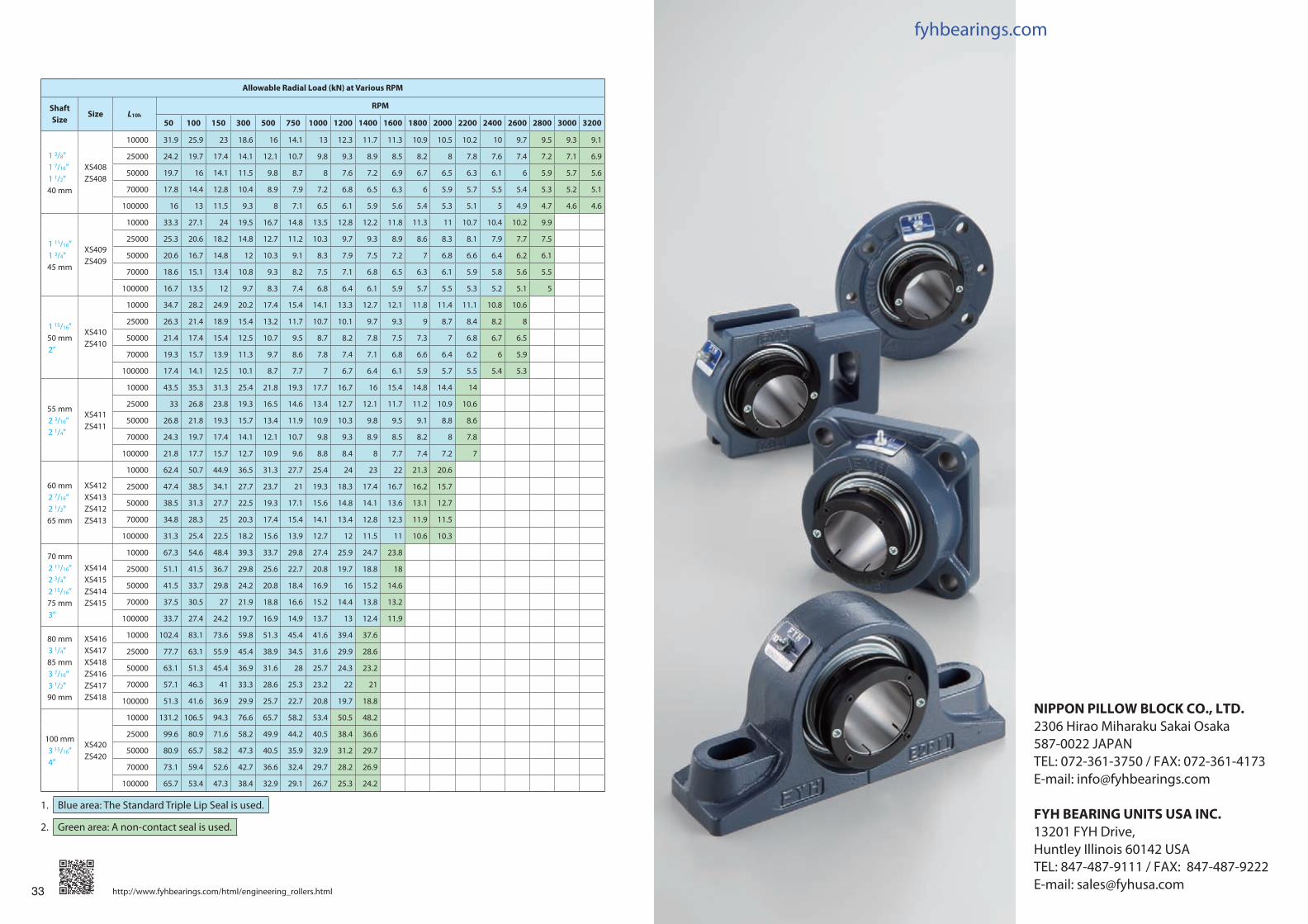
Allowable Radial Load (kN) at Various RPM
Shaft Size
Size L10h
RPM
50 100 150 300 500 750 1000 1200 1400 1600 1800 2000 2200 2400 2600 2800 3000 3200
1 3/8”1 7/16”1 1/2”40 mm
XS408ZS408
10000 31.9 25.9 23 18.6 16 14.1 13 12.3 11.7 11.3 10.9 10.5 10.2 10 9.7 9.5 9.3 9.1
25000 24.2 19.7 17.4 14.1 12.1 10.7 9.8 9.3 8.9 8.5 8.2 8 7.8 7.6 7.4 7.2 7.1 6.9
50000 19.7 16 14.1 11.5 9.8 8.7 8 7.6 7.2 6.9 6.7 6.5 6.3 6.1 6 5.9 5.7 5.6
70000 17.8 14.4 12.8 10.4 8.9 7.9 7.2 6.8 6.5 6.3 6 5.9 5.7 5.5 5.4 5.3 5.2 5.1
100000 16 13 11.5 9.3 8 7.1 6.5 6.1 5.9 5.6 5.4 5.3 5.1 5 4.9 4.7 4.6 4.6
1 11/16”1 3/4”45 mm
XS409ZS409
10000 33.3 27.1 24 19.5 16.7 14.8 13.5 12.8 12.2 11.8 11.3 11 10.7 10.4 10.2 9.9
25000 25.3 20.6 18.2 14.8 12.7 11.2 10.3 9.7 9.3 8.9 8.6 8.3 8.1 7.9 7.7 7.5
50000 20.6 16.7 14.8 12 10.3 9.1 8.3 7.9 7.5 7.2 7 6.8 6.6 6.4 6.2 6.1
70000 18.6 15.1 13.4 10.8 9.3 8.2 7.5 7.1 6.8 6.5 6.3 6.1 5.9 5.8 5.6 5.5
100000 16.7 13.5 12 9.7 8.3 7.4 6.8 6.4 6.1 5.9 5.7 5.5 5.3 5.2 5.1 5
1 15/16”50 mm2”
XS410ZS410
10000 34.7 28.2 24.9 20.2 17.4 15.4 14.1 13.3 12.7 12.1 11.8 11.4 11.1 10.8 10.6
25000 26.3 21.4 18.9 15.4 13.2 11.7 10.7 10.1 9.7 9.3 9 8.7 8.4 8.2 8
50000 21.4 17.4 15.4 12.5 10.7 9.5 8.7 8.2 7.8 7.5 7.3 7 6.8 6.7 6.5
70000 19.3 15.7 13.9 11.3 9.7 8.6 7.8 7.4 7.1 6.8 6.6 6.4 6.2 6 5.9
100000 17.4 14.1 12.5 10.1 8.7 7.7 7 6.7 6.4 6.1 5.9 5.7 5.5 5.4 5.3
55 mm2 3/16”2 1/4”
XS411ZS411
10000 43.5 35.3 31.3 25.4 21.8 19.3 17.7 16.7 16 15.4 14.8 14.4 14
25000 33 26.8 23.8 19.3 16.5 14.6 13.4 12.7 12.1 11.7 11.2 10.9 10.6
50000 26.8 21.8 19.3 15.7 13.4 11.9 10.9 10.3 9.8 9.5 9.1 8.8 8.6
70000 24.3 19.7 17.4 14.1 12.1 10.7 9.8 9.3 8.9 8.5 8.2 8 7.8
100000 21.8 17.7 15.7 12.7 10.9 9.6 8.8 8.4 8 7.7 7.4 7.2 7
60 mm2 7/16”2 1/2”65 mm
XS412XS413ZS412ZS413
10000 62.4 50.7 44.9 36.5 31.3 27.7 25.4 24 23 22 21.3 20.6
25000 47.4 38.5 34.1 27.7 23.7 21 19.3 18.3 17.4 16.7 16.2 15.7
50000 38.5 31.3 27.7 22.5 19.3 17.1 15.6 14.8 14.1 13.6 13.1 12.7
70000 34.8 28.3 25 20.3 17.4 15.4 14.1 13.4 12.8 12.3 11.9 11.5
100000 31.3 25.4 22.5 18.2 15.6 13.9 12.7 12 11.5 11 10.6 10.3
70 mm2 11/16”2 3/4”2 15/16”75 mm3”
XS414XS415ZS414ZS415
10000 67.3 54.6 48.4 39.3 33.7 29.8 27.4 25.9 24.7 23.8
25000 51.1 41.5 36.7 29.8 25.6 22.7 20.8 19.7 18.8 18
50000 41.5 33.7 29.8 24.2 20.8 18.4 16.9 16 15.2 14.6
70000 37.5 30.5 27 21.9 18.8 16.6 15.2 14.4 13.8 13.2
100000 33.7 27.4 24.2 19.7 16.9 14.9 13.7 13 12.4 11.9
80 mm3 1/4”85 mm3 7/16”3 1/2”90 mm
XS416XS417XS418ZS416ZS417ZS418
10000 102.4 83.1 73.6 59.8 51.3 45.4 41.6 39.4 37.6
25000 77.7 63.1 55.9 45.4 38.9 34.5 31.6 29.9 28.6
50000 63.1 51.3 45.4 36.9 31.6 28 25.7 24.3 23.2
70000 57.1 46.3 41 33.3 28.6 25.3 23.2 22 21
100000 51.3 41.6 36.9 29.9 25.7 22.7 20.8 19.7 18.8
100 mm3 15/16”4”
XS420ZS420
10000 131.2 106.5 94.3 76.6 65.7 58.2 53.4 50.5 48.2
25000 99.6 80.9 71.6 58.2 49.9 44.2 40.5 38.4 36.6
50000 80.9 65.7 58.2 47.3 40.5 35.9 32.9 31.2 29.7
70000 73.1 59.4 52.6 42.7 36.6 32.4 29.7 28.2 26.9
100000 65.7 53.4 47.3 38.4 32.9 29.1 26.7 25.3 24.2
1. Blue area: The Standard Triple Lip Seal is used.
2. Green area: A non-contact seal is used.

fyhbearings.com
CATALOG NO.12020b2017.05
®
®
SPHERICAL ROLLER BEARING UNITS


