
SpeedAndFeeds_CombinedExcelCalculators
46
1.000 30.000 1.000 1.50028 32.149 45.000 29.000 45.48333 974.643 2.000 0.00056 0.012 4.000 0.00111 0.024 10.000 0.00278 0.060 85.000 0.02361 0.506 1.000 0.01667 0.357 1.000 1.00000 21.429 1.000 0.00028 0.006 10.000 0.00278 0.060 100.000 0.02778 0.595 1000.000 0.27778 5.952 Find Sec 16.667 0.005 33.333 0.010 83.333 0.024 333.333 0.095 Enter Degree Enter Minute Enter Second Dedgee in Decimal Distance across in Inches at 100 feet Find Degree in Decimal
-
Upload
xuanphuong2710 -
Category
Documents
-
view
213 -
download
0
description
SpeedAndFeeds_CombinedExcelCalculators
Transcript of SpeedAndFeeds_CombinedExcelCalculators
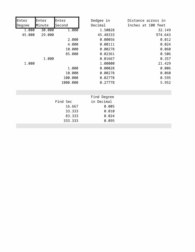
Enter Second1.000 30.000 1.000 1.50028 32.149 0.3215
45.000 29.000 45.48333 974.643 9.74642.000 0.00056 0.012 0.00014.000 0.00111 0.024 0.0002
10.000 0.00278 0.060 0.000685.000 0.02361 0.506 0.0051
1.000 0.01667 0.357 0.00361.000 1.00000 21.429 0.2143
1.000 0.00028 0.006 0.000110.000 0.00278 0.060 0.0006
100.000 0.02778 0.595 0.00601000.000 0.27778 5.952 0.0595
Find Sec Find Dist per ft16.667 0.005 0.001033.333 0.010 0.002083.333 0.024 0.0050
333.333 0.095 0.0200
Enter Degree
Enter Minute
Dedgee in Decimal
Distance across in Inches at 100 feet
Distance across in Inches at 1 ft
Find Degree in Decimal
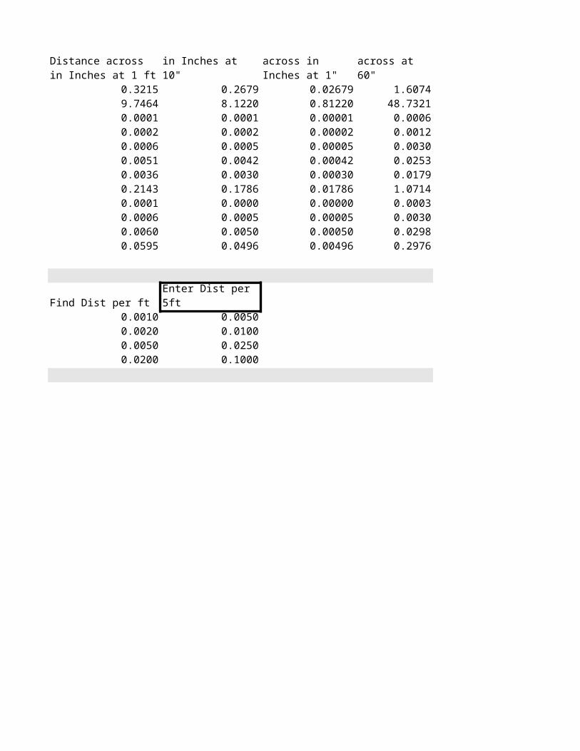
0.2679 0.02679 1.60748.1220 0.81220 48.73210.0001 0.00001 0.00060.0002 0.00002 0.00120.0005 0.00005 0.00300.0042 0.00042 0.02530.0030 0.00030 0.01790.1786 0.01786 1.07140.0000 0.00000 0.00030.0005 0.00005 0.00300.0050 0.00050 0.02980.0496 0.00496 0.2976
Enter Dist per 5ft0.00500.01000.02500.1000
Distance across in Inches at 10"
Distance across in Inches at 1"
Distance across at 60"
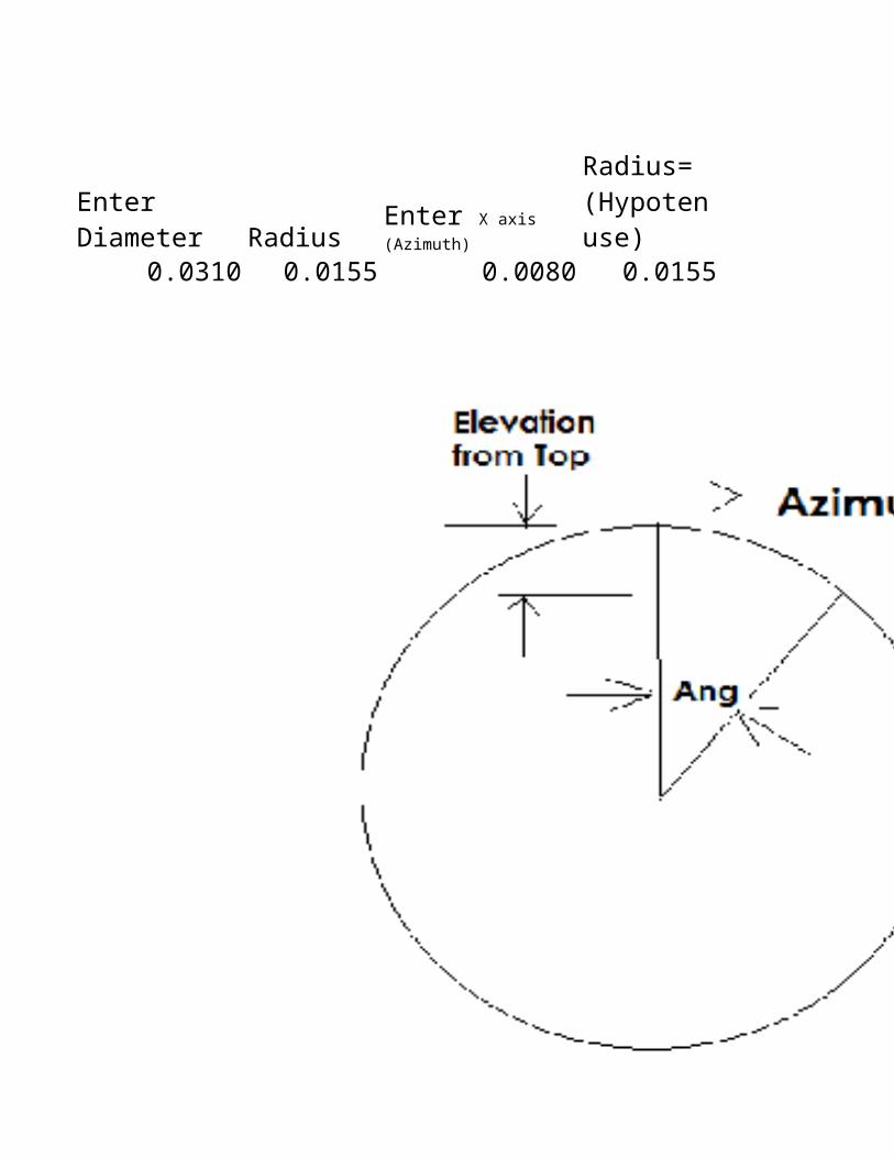
Radius0.0310 0.0155 0.0080 0.0155 0.5161
Enter Diameter
Enter X axis (Azimuth)
Radius= (Hypotenuse)
Sine=Azimuth/Hyp
Radius

Radius
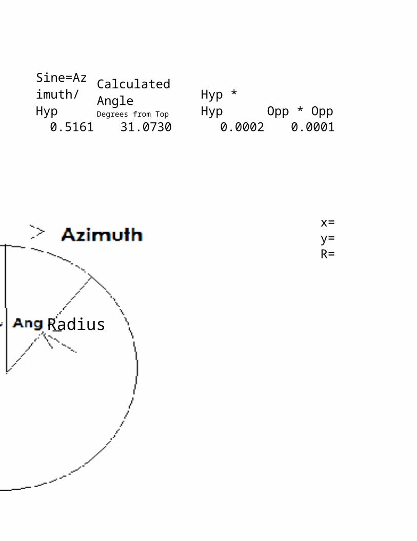
31.0730 0.0002 0.0001 0.0133 0.0022
x= 0.0080y= 0.0133R= 0.0155
Calculated Angle Degrees from Top
Hyp * Hyp
Opp * Opp
Adj = SqRt of H*H+O*O
Calculated Elevation from Top (Radius-Adj)
Radius

Radius

0.0133 0.0160
Calculated Y=Radius-Elev from Top
Width of 2X Azimuth

Ball End Mill Elevation down to Width of lineDiameter
0.0625
Radius ½ Width0.0313 0.0150 0.0163Rad^2 ^2 K15-M15 SqrtM15 O15*20.0010 0.0003 0.0007 0.0267 0.0534
Diameter0.0625 0.0050 0.0339 0.27120.0625 0.0100 0.0458 0.36640.0625 0.0150 0.0534 0.42720.0938 0.0150 0.0688 0.55040.0938 0.0200 0.0768 0.61440.0938 0.0250 0.0829 0.66320.0938 0.0300 0.0875 0.70000.1250 0.0200 0.0917 0.73360.1250 0.0300 0.1068 0.85440.1250 0.0400 0.1166 0.93280.1250 0.0500 0.1225 0.9800
Elev from Top
Rad-Elev from top
2x(1/2 Widths)
Elev from Top
Width of Line
Height of Letter (X8)

Coefficient of expansion Aluminum Inch per degree F 0.000013Coefficient of expansion Steel Inch per degree F 0.000006
Length of Aluminum metal Inches Temperature difference in F Length change12.0000 30.0 0.0047
Length of Steel metal Inches Temperature difference in F Length change100.0000 30.0 0.0180

Metal Weight CalculatorSS 0.29Steel 0.25Aluminum 0.1
Length Width Height Pounds per Cubic Inch Weight Of Piece in Lbs12 12 12 0.25 43248 48 0.375 0.1 86.412 12 1 0.1 14.412 12 0.25 0.1 3.6
00000000

SpeedAndFeed40
Page 11
500 0.5000 4 1.50350 0.5000 4 1.50
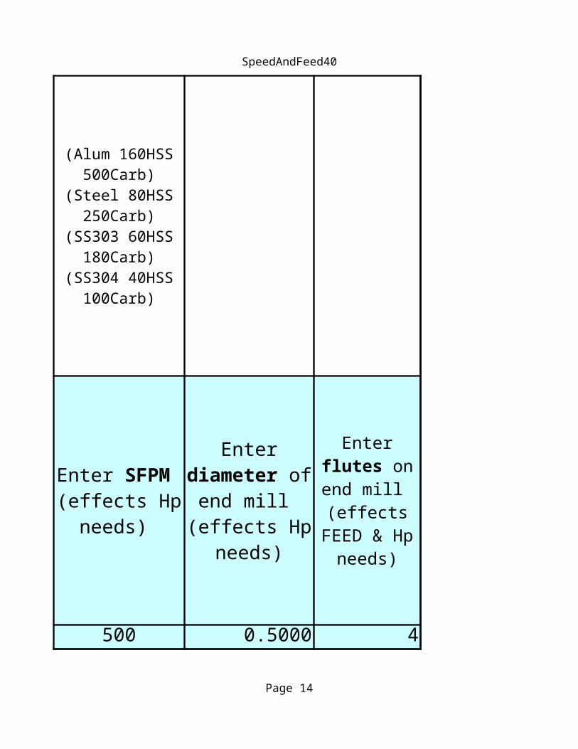
(Alum 160HSS 500Carb)
(Steel 80HSS 250Carb)
(SS303 60HSS 180Carb)
(SS304 40HSS 100Carb)
(Aluminum=3.0) (Alum Alloy=1.5) (HR Steel=0.8) (SS 304=0.35)
Enter SFPM (effects Hp
needs)
Enter diameter of
end mill (effects Hp
needs)
Enter flutes on end mill (effects FEED &
Hp needs)
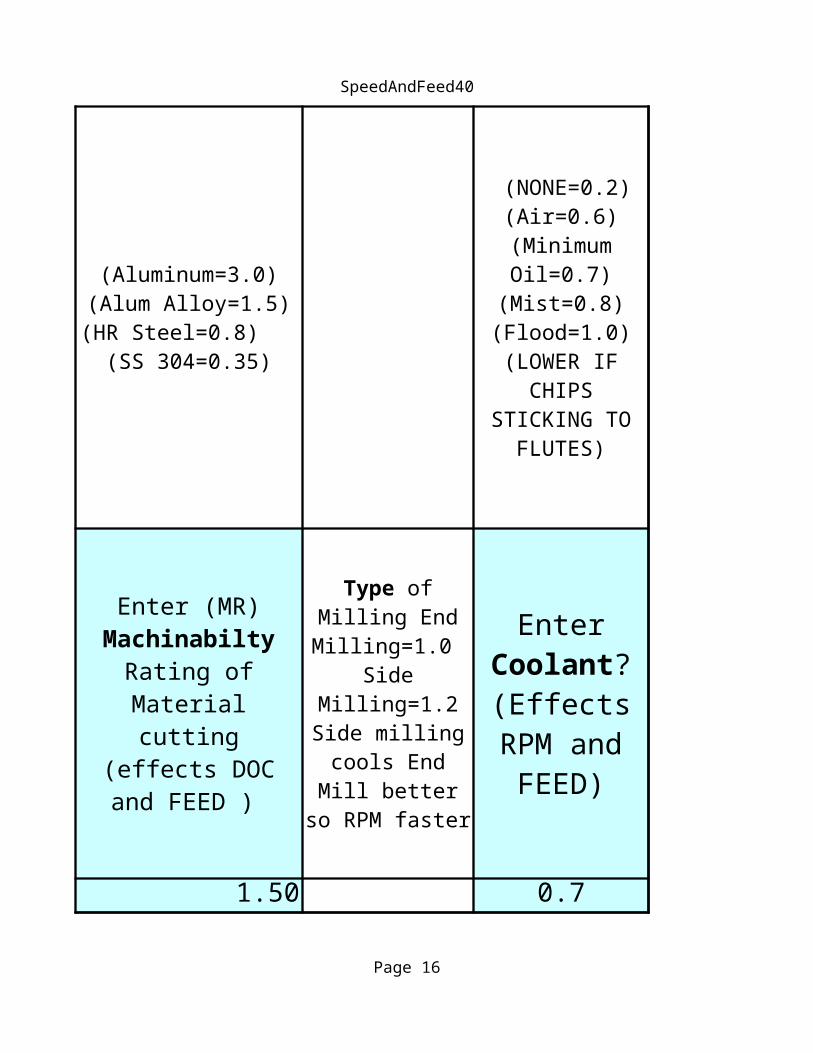
Enter (MR) Machinabilty
Rating of Material cutting
(effects DOC and FEED )

SpeedAndFeed40
Page 12
420 0.5000 4 1.50
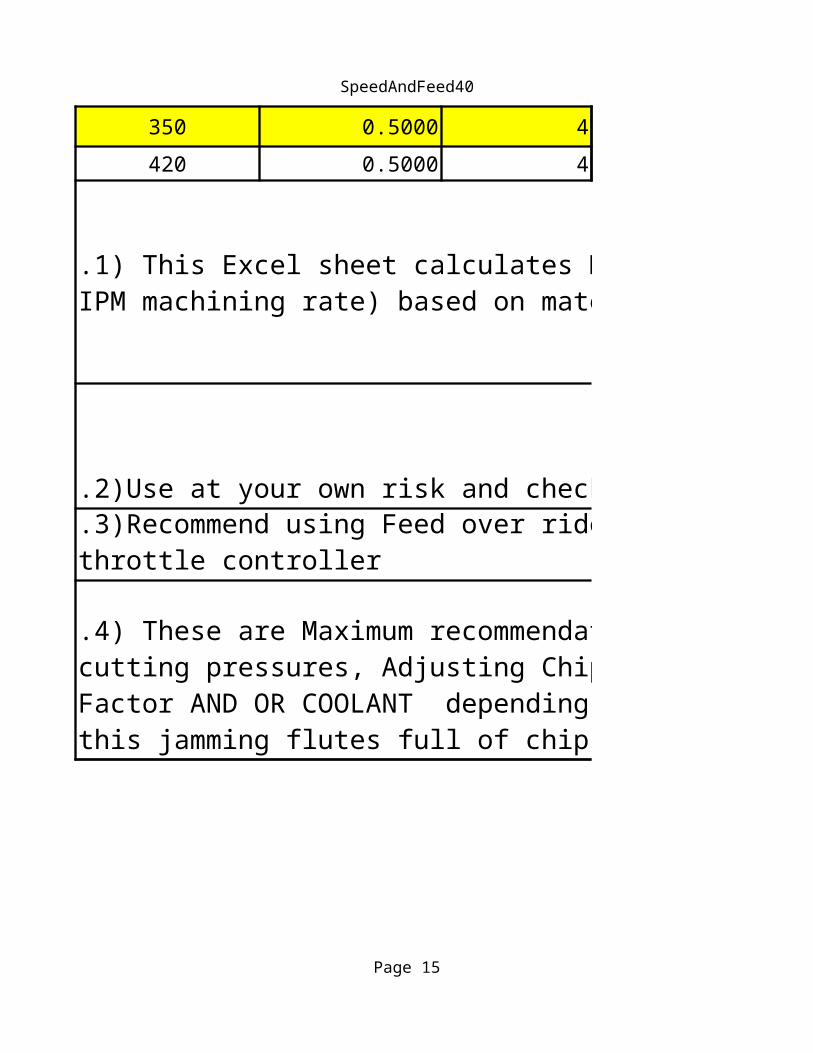
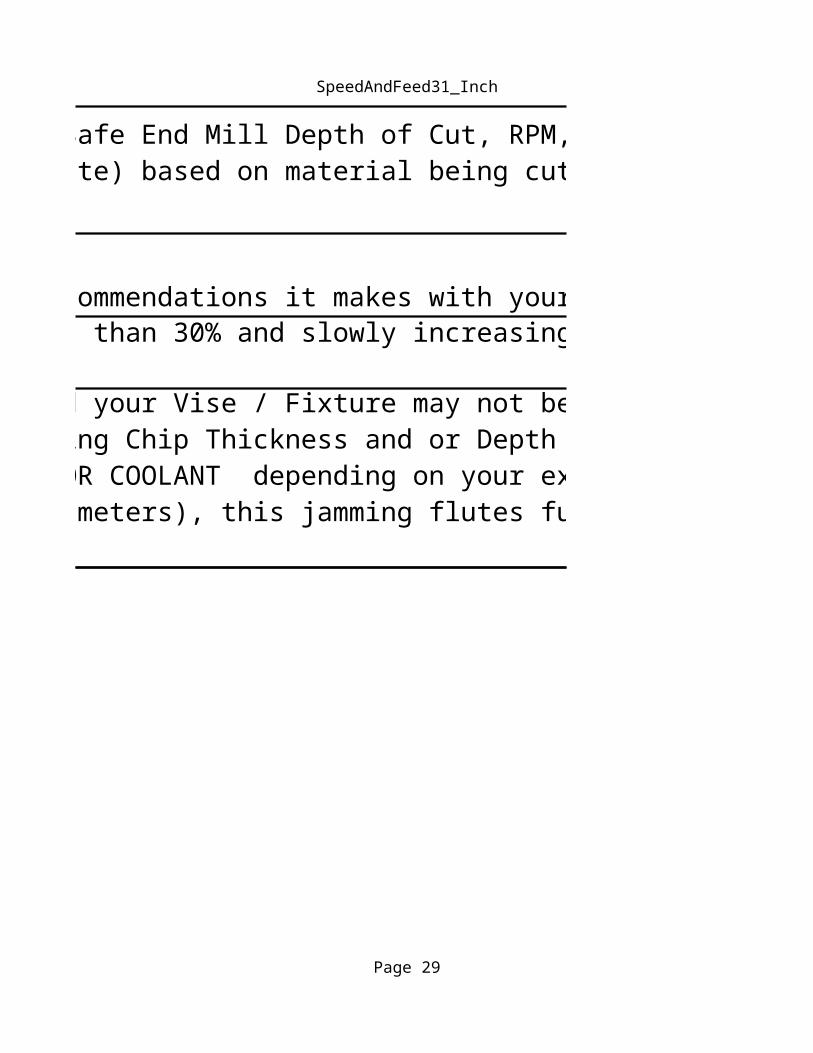
.2)Use at your own risk and check all recommendations it makes with your own calculations.
.3)Recommend using Feed over ride at less than 30% and slowly increasing if everything looks OK. Feed is the main throttle controller
.1) This Excel sheet calculates Maximum Safe End Mill Depth of Cut, RPM, Feed, and Horsepower requirements ( and Cubic IPM machining rate) based on material being cut and End mill diameter, length and number of flutes.
.4) These are Maximum recommendations and your Vise / Fixture may not be able to hold part and or it may bend under cutting pressures, Adjusting Chip Thickness and or Depth of Cut Divider and or Material Ratings and or Cutter Length Factor AND OR COOLANT depending on your experiences. Watch for chips packing in flutes (especially smaller diameters), this jamming flutes full of chips can destroy an end mill quickly.

SpeedAndFeed40
Page 13
0.7 2.0 0.0033End Milling 0.7 2.0 0.0030
(NONE=0.2) (Air=0.6) (Minimum Oil=0.7)
(Mist=0.8) (Flood=1.0) (LOWER IF
CHIPS STICKING TO
FLUTES)
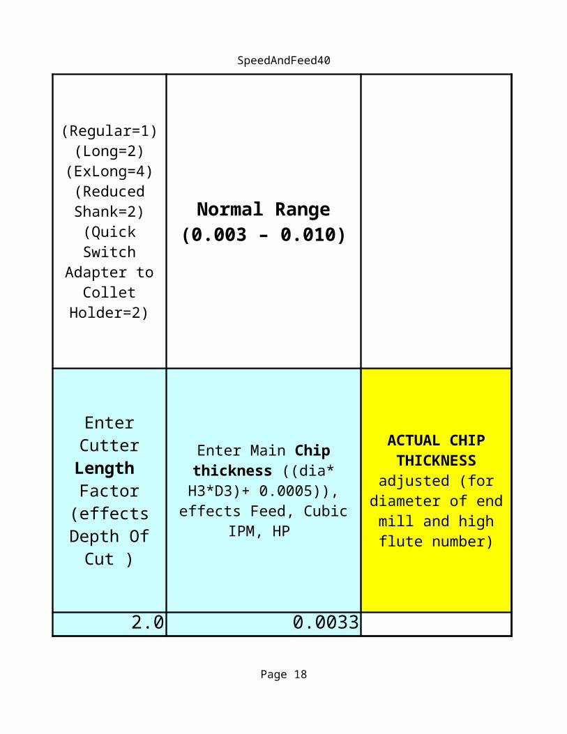
(Regular=1) (Long=2)
(ExLong=4) (Reduced Shank=2)
(Quick Switch Adapter to
Collet Holder=2)
Normal Range (0.003 – 0.010)
Type of Milling End Milling=1.0
Side Milling=1.2 Side milling
cools End Mill better so RPM
faster
Enter Coolant? (Effects
RPM and FEED)
Enter Cutter Length Factor (effects
Depth Of Cut )
Enter Main Chip thickness ((dia*
H3*D3)+ 0.0005)), effects Feed, Cubic
IPM, HP
SpeedAndFeed40
Page 14
Side Milling 0.7 2.0 0.0030
.2)Use at your own risk and check all recommendations it makes with your own calculations.
.3)Recommend using Feed over ride at less than 30% and slowly increasing if everything looks OK. Feed is the main throttle controller
.1) This Excel sheet calculates Maximum Safe End Mill Depth of Cut, RPM, Feed, and Horsepower requirements ( and Cubic IPM machining rate) based on material being cut and End mill diameter, length and number of flutes.
.4) These are Maximum recommendations and your Vise / Fixture may not be able to hold part and or it may bend under cutting pressures, Adjusting Chip Thickness and or Depth of Cut Divider and or Material Ratings and or Cutter Length Factor AND OR COOLANT depending on your experiences. Watch for chips packing in flutes (especially smaller diameters), this jamming flutes full of
SpeedAndFeed40
Page 15
RPM
0.0025 0.835 1.253 2674
ACTUAL CHIP THICKNESS adjusted (for
diameter of end mill and high flute
number)
HP needs = Cubic IPM /
MR (Bridgeport
<1) (Sherline <0.025)
Adjusted cubic IPM
SpeedAndFeed40
Page 16
0.0025 1.193 1.790 3209
.2)Use at your own risk and check all recommendations it makes with your own calculations.
.3)Recommend using Feed over ride at less than 30% and slowly increasing if everything looks OK. Feed is the main throttle controller
.1) This Excel sheet calculates Maximum Safe End Mill Depth of Cut, RPM, Feed, and Horsepower requirements ( and Cubic IPM
.4) These are Maximum recommendations and your Vise / Fixture may not be able to hold part and or it may bend under cutting pressures, Adjusting Chip Thickness and or Depth of Cut Divider and or Material Ratings and or Cutter Length Factor AND OR COOLANT depending on your experiences. Watch for chips packing in flutes (especially smaller diameters), this jamming flutes full of

SpeedAndFeed40
Page 17
4.0
2.026.7 0.16 31.8 0.094
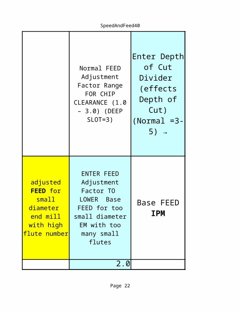
Normal FEED Adjustment
Factor Range FOR CHIP
CLEARANCE (1.0 – 3.0) (DEEP
SLOT=3)
Enter Depth of Cut
Divider (effects Depth of
Cut) (Normal =3-
5) →
adjusted FEED for
small diameter
end mill with high flute number
ENTER FEED Adjustment Factor TO
LOWER Base FEED for too
small diameter EM with too many
small flutes
Base FEED IPM
Depth Of Cut is Dia x MR / (LF x Depth
Divider)
SpeedAndFeed40
Page 18
32.1 0.16 38.2 1.000
0.250
678.9 = 2.38125
Enter Side Milling Depth
Changed to ----→
End Milling FEED
METRIC MM
End Milling Depth METRIC
MM

SpeedAndFeed40
Page 19
Stepover
0.500

SpeedAndFeed40
Page 20
0.047
0.188

SpeedAndFeed31_Inch
Page 21
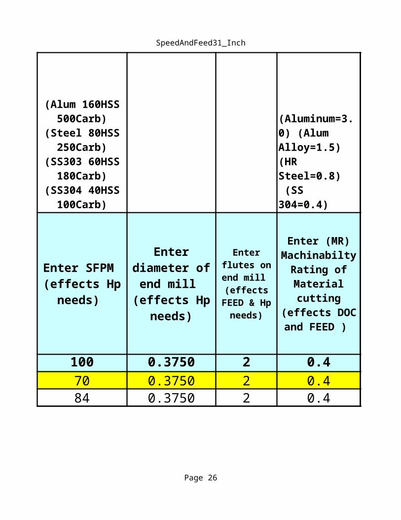
100 0.3750 2 0.470 0.3750 2 0.484 0.3750 2 0.4
(Alum 160HSS 500Carb)
(Steel 80HSS 250Carb)
(SS303 60HSS 180Carb)
(SS304 40HSS 100Carb)
(Aluminum=3.0) (Alum Alloy=1.5) (HR Steel=0.8) (SS 304=0.4)
Enter SFPM (effects Hp
needs)
Enter diameter of
end mill (effects Hp
needs)
Enter flutes on end mill (effects
FEED & Hp needs)
Enter (MR) Machinabilty
Rating of Material cutting
(effects DOC and FEED )
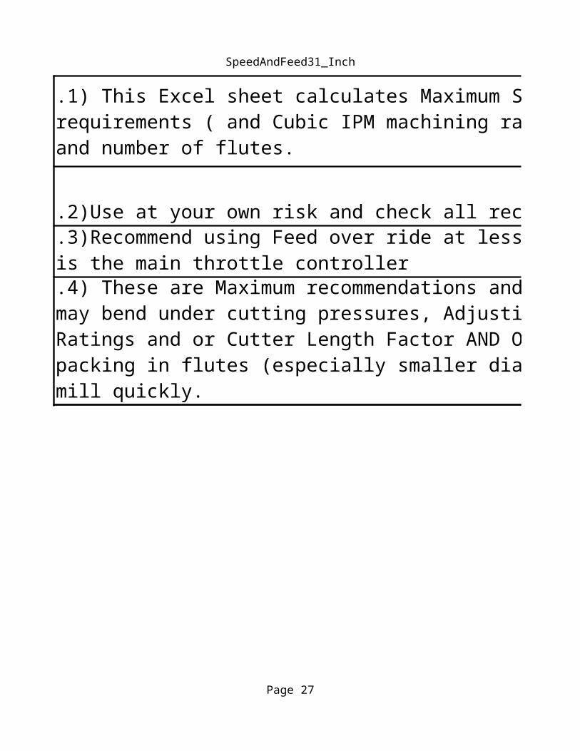
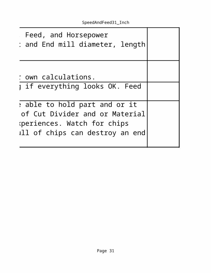
.1) This Excel sheet calculates Maximum Safe End Mill Depth of Cut, RPM, Feed, and Horsepower requirements ( and Cubic IPM machining rate) based on material being cut and End mill diameter, length and number of flutes.
SpeedAndFeed31_Inch
Page 22
.2)Use at your own risk and check all recommendations it makes with your own calculations.
.3)Recommend using Feed over ride at less than 30% and slowly increasing if everything looks OK. Feed is the main throttle controller
.4) These are Maximum recommendations and your Vise / Fixture may not be able to hold part and or it may bend under cutting pressures, Adjusting Chip Thickness and or Depth of Cut Divider and or Material Ratings and or Cutter Length Factor AND OR COOLANT depending on your experiences. Watch for chips packing in flutes (especially smaller diameters), this jamming flutes full of chips can destroy an end mill quickly.

SpeedAndFeed31_Inch
Page 23
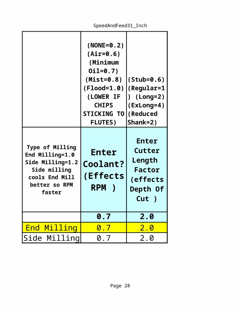
0.7 2.0 0.0070End Milling 0.7 2.0 0.0016Side Milling 0.7 2.0 0.0016
(NONE=0.2) (Air=0.6)
(Minimum Oil=0.7)
(Mist=0.8) (Flood=1.0) (LOWER IF
CHIPS STICKING
TO FLUTES)
(Stub=0.6) (Regular=1) (Long=2) (ExLong=4) (Reduced Shank=2)
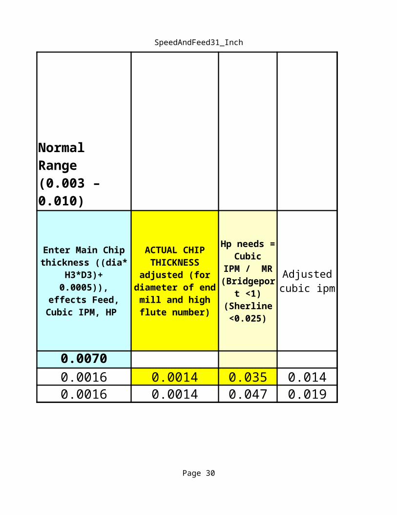
Normal Range (0.003 – 0.010)
Type of Milling End Milling=1.0 Side Milling=1.2
Side milling cools End Mill better so
RPM faster
Enter Coolant
? (Effects RPM )
Enter Cutter
Length Factor (effects
Depth Of Cut )
Enter Main Chip thickness ((dia*
H3*D3)+ 0.0005)), effects Feed,
Cubic IPM, HP
.1) This Excel sheet calculates Maximum Safe End Mill Depth of Cut, RPM, Feed, and Horsepower requirements ( and Cubic IPM machining rate) based on material being cut and End mill diameter, length and number of flutes.

SpeedAndFeed31_Inch
Page 24
.2)Use at your own risk and check all recommendations it makes with your own calculations.
.3)Recommend using Feed over ride at less than 30% and slowly increasing if everything looks OK. Feed is the
.4) These are Maximum recommendations and your Vise / Fixture may not be able to hold part and or it may bend under cutting pressures, Adjusting Chip Thickness and or Depth of Cut Divider and or Material Ratings and or Cutter Length Factor AND OR COOLANT depending on your experiences. Watch for chips packing in flutes (especially smaller diameters), this jamming flutes full of chips can destroy an end mill quickly.

SpeedAndFeed31_Inch
Page 25
RPM
0.0014 0.035 0.014 713 2.00.0014 0.047 0.019 856 2.4
ACTUAL CHIP THICKNESS adjusted (for
diameter of end mill and high flute number)
Hp needs = Cubic
IPM / MR (Bridgepor
t <1) (Sherline <0.025)
Adjusted cubic ipm
adjusted FEED for
small diameter end mill
with high flute
number
.1) This Excel sheet calculates Maximum Safe End Mill Depth of Cut, RPM, Feed, and Horsepower requirements ( and Cubic IPM machining rate) based on material being cut and End mill diameter, length and number of flutes.
SpeedAndFeed31_Inch
Page 26
.2)Use at your own risk and check all recommendations it makes with your own calculations. METRIC MM
50.2.3)Recommend using Feed over ride at less than 30% and slowly increasing if everything looks OK. Feed is the
.4) These are Maximum recommendations and your Vise / Fixture may not be able to hold part and or it may bend under cutting pressures, Adjusting Chip Thickness and or Depth of Cut Divider and or Material Ratings and or Cutter Length Factor AND OR COOLANT depending on your experiences. Watch for chips packing in flutes (especially
SpeedAndFeed31_Inch
Page 27
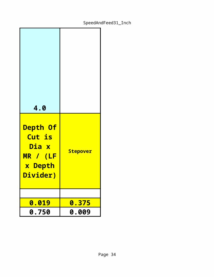
4.0
Stepover
2.00.11 2.2 0.019 0.3750.11 2.7 0.750 0.009
Normal FEED Adjustment Factor Range FOR CHIP CLEARANCE (1.0 – 3.0) (DEEP SLOT=3)
Enter Depth of Cut Divider (effects Depth of Cut) (Normal =3-5)
→
ENTER FEED Adjustment Factor TO
LOWER Base FEED for too
small diameter EM
with too many small
flutes
Base FEED ipm
Depth Of Cut is Dia x
MR / (LF x Depth Divider)
SpeedAndFeed31_Inch
Page 28
= 0.47625
METRIC MM
MM TAP SIZES MM
0.0135 80 0.3429 0.1181 3.00000.0145 79 0.3683 0.1200 31 3.04800.0156 1/64 0.3962 0.1250 1/8 3.17500.0157 0.4000 0.1285 30 3.26390.0160 78 0.4064 0.1299 3.30000.0180 77 0.4572 0.1360 29 3.45440.0197 0.5000 0.1405 28 3.56870.0200 76 0.5080 0.1406 9/64 3.57120.0210 75 0.5334 0.1440 27 3.65760.0225 74 0.5715 0.1457 3.70000.0236 0.6000 0.1470 26 3.73380.0240 73 0.6096 0.1495 25 3.79730.0250 72 0.6350 0.1520 24 3.86080.0260 71 0.6604 0.1540 23 3.91160.0276 0.7000 0.1562 5/32 3.96750.0280 70 0.7112 0.1570 22 3.98780.0292 69 0.7417 0.1575 4.00000.0295 0.7500 M1 X 0.25 0.1590 21 4.03860.0310 68 0.7874 0.1610 20 4.08940.0313 1/32 0.7938 0.1654 4.20000.0315 0.8000 0.1660 19 4.21640.0320 67 0.8128 0.1695 18 4.30530.0330 66 0.8382 0.1719 11/64 4.36630.0335 0.8500 M1.1 X 0.25 0.1730 17 4.39420.0350 65 0.8890 0.1770 16 4.49580.0354 0.9000 0.1800 15 4.57200.0360 64 0.9144 0.1820 14 4.62280.0370 63 0.9398 0.1850 13 4.69900.0374 0.9500 M1.2 X 0.25 0.1875 3/16 4.76250.0380 62 0.9652 0.1890 12 4.80060.0390 61 0.9906 0.1910 11 4.85140.0394 1.0000 0.1935 10 4.91490.0400 60 1.0160 0.1960 9 4.97840.0410 59 1.0414 0.1969 5.00000.0420 58 1.0668 0.1990 8 5.05460.0430 57 1.0922 0.2010 7 5.1054
DECIMAL EQUIV
DRILL SIZE
DECIMAL EQUIV
DRILL SIZE
0.0433 1.1000 M1.4 X 0.3 0.2031 13/64 5.15870.0465 56 1.1811 0.2040 6 5.18160.0469 3/64 1.1913 #0-80 0.2055 5 5.21970.0492 1.2500 M1.6 X 0.35 0.2090 4 5.30860.0520 55 1.3208 0.2130 3 5.41020.0550 54 1.3970 0.2188 7/32 5.55750.0595 53 1.5113 #1-64, #-72 0.2210 2 5.61340.0625 1/16 1.5875 0.2280 1 5.79120.0630 1.6000 M2 X 0.4 0.2340 A 5.94360.0635 52 1.6129 0.2344 15/64 5.95380.0670 51 1.7018 0.2362 6.00000.0689 1.7500 M2.2 X 0.45 0.2380 B 6.04520.0700 50 1.7780 #2-56, #2-64 0.2420 C 6.14680.0730 49 1.8542 0.2460 D 6.24840.0760 48 1.9304 0.2500 1/4&E 6.35000.0781 5/64 1.9837 0.2570 F 6.52780.0785 47 1.9939 #3-48 0.2610 G 6.62940.0787 2.0000 0.2656 17/64 6.74620.0807 2.0500 M2 X 0.045 0.2660 H 6.75640.0810 46 2.0574 0.2677 6.79960.0820 45 2.0828 #3-56 0.2720 I 6.90880.0860 44 2.1844 0.2756 7.00000.0890 43 2.2606 #4-40 0.2770 J 7.03580.0935 42 2.3749 #4-48 0.2810 K 7.13740.0938 3/32 2.3825 0.2812 9/32 7.14250.0960 41 2.4384 0.2900 L 7.36600.0980 40 2.4892 0.2950 M 7.49300.0984 2.5000 M3 X 1.5 0.2969 19/64 7.54130.0995 39 2.5273 0.3020 N 7.67080.1015 38 2.5781 #5-40 0.3071 7.80000.1040 37 2.6416 #5-44 0.3125 5/16 7.93750.1065 36 2.7051 #6-32 0.3150 8.00000.1094 7/64 2.7788 0.3160 O 8.02640.1100 35 2.7940 0.3230 P 8.20420.1110 34 2.8194 0.3281 21/64 8.33370.1130 33 2.8702 #6-40 0.3320 Q 8.43280.1142 2.9000 M3.5 x 0.6 0.3346 8.50000.1160 32 2.9464 0.3390 R 8.6106
TAP SIZES MM
0.3438 11/32 8.73250.3480 S 8.83920.3543 9.00000.3580 T 9.0932
M4 x 0.7 0.3594 23/64 9.1288#8-32, #8-36 0.3680 U 9.3472
0.3750 3/8 9.52500.3770 V 9.57580.3860 W 9.8044
M4.5 x 0.75 0.3906 25/64 9.92120.3937 10.0000
#10-24 0.3970 X 10.08380.4016 10.20000.4040 Y 10.26160.4062 13/32 10.31750.4130 Z 10.49020.4219 27/64 10.7163
#10-32 0.4331 11.00000.4375 7/16 11.1125
M5 x 0.8 0.4531 29/64 11.50870.4688 15/32 11.90750.4724 12.00000.4844 31/64 12.30380.5000 1/2 12.7000
#12-24 0.5118 13.00000.5156 33/64 13.0962
#12-28 0.5312 17/32 13.4925#12-32
0.5469 35/64 13.89130.5512 14.00000.5625 9/16 14.28750.5781 37/64 14.68370.5906 15.0000
M6 x 1.0 0.5938 19/32 15.08250.6094 39/64 15.4788
1/4-20 0.6102 15.5000
DECIMAL EQUIV
DRILL SIZE

0.6250 5/8 15.87500.6299 16.00000.6406 41/64 16.27120.6562 21/32 16.6675
1/4-28, 1/4-32 0.6693 17.00000.6719 43/64 17.06630.6875 11/16 17.46250.6890 17.50000.7031 45/64 17.8587
M7 x 1.0 0.7087 18.00000.7188 23/32 18.25750.7344 47/64 18.65380.7480 19.00000.7500 3/4 19.0500
5/16-18 0.7656 49/64 19.44620.7677 19.5000
5/16-20 0.7812 25/32 19.84250.7874 20.0000
M8 x 1.25 0.7969 51/64 20.24135/16-24 0.8125 13/16 20.6375
0.8268 21.00005/16-28 0.8281 53/64 21.0337
0.8438 27/32 21.43250.8594 55/64 21.82880.8661 22.00000.8750 7/8 22.22500.8906 57/64 22.62120.9055 23.0000
M9 x 1.25 0.9062 29/32 23.01753/8-16 0.9219 59/64 23.4163
0.9375 15/16 23.81250.9449 24.00000.9531 61/64 24.2087
3/8-20 0.9688 31/32 24.60750.9843 25.0000
M10 x 1.5 0.9844 63/64 25.00383/8-24 1.0000 1 25.4000

TAP SIZES
3/8-28, 3/8-32
7/16-147/16-16
7/16-20
M12 x 1.757/16-287/16-32
1/2-13
1/2-161/2-20
1/2-28, 1/2-32M14 x 2.09/16-129/16-16
9/16-18, 9/16-209/16-24, 9/16-289/16-32, 5/8-11
5/8-12M16 x 2.0
5/8-165/8-18, 5/8-20
5/8-24, 5/8-28, 5/8-3211/16-12M18 x 2.5
11/16-16
11/16-2011/16-24, 11/16-28
11/16-32, 3/4-10
3/4-123/4-16
M20 x 2.53/4-20
3/4-28, 3/4-3213/16-12
13/16-1613/16-20, 7/8-9
M22 x 2.513/16-32
7/8-127/8-14, 7/8-16
M24 x 3.07/8-20
7/8-28, 7/8-3215/16-12
15/16-16, 1.0-815/16-20
15/16-28, 15/16-321.0-12
1.0-16, 1-1/16-8M27 x 3.0
1.0-201.0-28, 1.0-32
1-1/16-12, 1-1/8-71-1/16-16, 1-1/8-8

Thread Depth
Page 35
Double Depth of American National Thread
Factor1.3000
3.5 1.3000 0.371 0.4289 0.2144 0.03574.0 1.3000 0.325 0.3753 0.1876 0.03134.5 1.3000 0.289 0.3336 0.1668 0.0278
5 1.3000 0.260 0.3002 0.1501 0.02506 1.3000 0.217 0.2502 0.1251 0.02087 1.3000 0.186 0.2144 0.1072 0.01798 1.3000 0.163 0.1876 0.0938 0.01569 1.3000 0.144 0.1668 0.0834 0.0139
10 1.3000 0.130 0.1501 0.0751 0.012511 1.3000 0.118 0.1365 0.0682 0.011412 1.3000 0.108 0.1251 0.0625 0.010413 1.3000 0.100 0.1155 0.0577 0.009614 1.3000 0.093 0.1072 0.0536 0.008916 1.3000 0.081 0.0938 0.0469 0.007818 1.3000 0.072 0.0834 0.0417 0.006920 1.3000 0.065 0.0751 0.0375 0.006324 1.3000 0.054 0.0625 0.0313 0.005228 1.3000 0.046 0.0536 0.0268 0.004532 1.3000 0.041 0.0469 0.0235 0.003940 1.3000 0.033 0.0375 0.0188 0.0031
1.3000 #DIV/0!
Number of Threads
Double Depth (Lathe Cross slide)
Double Depth using Compound at 30 degree
Compound at 30 degree direct reading
Flat on Cutter Tip

Xsq + Ysq=Rsq Xsq+Yysq=Rad(Hyp)sq
Xsq= Rsq – Ysq
T0 FIND MISSING Y ENTER X
10.0000 Enter Diameter= 10.0000 Enter X=
Rad= 5.0000 Rad= 5.0000 Xsq=
Enter Y= 3.0000 Enter X= 3.0000 Enter Y=
XSQ= 16.0000 Ysq= 16.0000 Ysq=
Then X= 4.0000 Then Y= 4.0000 Radius(Hyp)sq=
Radius (Hyp) =X,Y Coordinates X,Y Coordinates
X Y X Y
4.0000 3.0000 3.0000 4.0000
X and Y cannot be bigger than Radius
If one corner of triangle is X0,Y0
T0 FIND MISSING X ENTER Diameter AND Y
To Find Radius (Hyp) if you know X and Y of other
corner
Enter Diameter=

Xsq+Yysq=Rad(Hyp)sq Sine =Opp/Hyp
Cosine= Adj/Hyp
Tangent =Opp/Adj Sine 30.0000 0.5000 ArcSin 0.5000
2.0000 Cosine 30.0000 0.8660 ArcCos 0.8660
4.0000 Tangent 45.0000 1.0000 ArcTan 1.0000
2.0000 12.0000
4.0000 12.0000
8.0000
2.8284 Enter Angle 45.0000Sine Cosine Tangent Opp Adj Hyp
45.0000 45.0000 45.0000 12.0000 12.0000 0.00000.7071 0.7071 1.0000
0.0000
16.9706
0.0000
16.9706
12.0000
12.0000
Indexing Table 1.0000 -179.00002.0000 -178.00003.0000 -177.00004.0000 -176.00005.0000 -175.0000
6.0000 -174.0000
If one corner of triangle is X0,Y0
Enter Degrees
Gives Number
Enter Number
To Find Radius (Hyp) if you know X and Y of other
corner
Enter Opp (Leave Blank if not sure)
Enter Adj (Leave Balnk If not sure)
Enter Hyp (Leave Blank if not sure)
Opp=Sine * Hyp
Hyp= Opp/Sine
Adj = Cosine * Hyp
Hyp = Adj/Cosine
Opp = Tan * Adj
Adj = Opp/Tan
Enter degrees
Degrees – 180

-180.0000-180.0000-180.0000-180.0000

30.0000
30.0029
45.0000
Gives Degrees


