Speed-Sensorless AC Drives With the Rotor Time Constant Parameter
8
2618 IEEE TRANSACTIONS ON INDUSTRIAL ELECTRONICS, VOL. 54, NO. 5, OCTOBER 2007 Speed-Sensorless AC Drives With the Rotor Time Constant Parameter Update Darko P. Marˇ ceti´ c, Member, IEEE, and Slobodan N. Vukosavi´ c, Member, IEEE Abstract—This paper presents a new technique for online iden- tification of an induction motor rotor time constant. The technique is designed for a shaft-sensorless indirect field-oriented control induction motor drive with a model reference adaptive system (MRAS)-based speed estimator. The MRAS estimator is sensitive to the changes in the rotor time constant, and online identification of that parameter is essential. If rotor parameter error exists, it does not only change the achieved rotor speed, but it also changes the dynamic behavior of the whole field control and speed esti- mation structure. The proposed rotor parameter update is exactly based on the newly introduced dynamic model of the potentially detuned MRAS-based speed estimator. The technique avoids the use of test signals and rather extracts the needed information from the ever-present signal jitter, which is inherent to the current and speed servo loops. This paper demonstrates that the phase angle difference between some spectral components of selected small signals within the speed estimator can be used for rotor parameter update. Computer simulations and experiments are performed under a variety of conditions to validate the effectiveness of the proposed rotor parameter update technique. Index Terms—AC motor drives, model reference adaptive control, parameter estimation. I. I NTRODUCTION H IGH-PERFORMANCE servo applications of an induc- tion motor can be made possible by implementing the vector control technology. This advance in control technology, coupled with consistent price reduction in power electronics, made the vector-controlled induction motor highly competitive on the low-cost motor system market. Further advance in the induction motor drive technology is also feasible, and it is coupled with the elimination of the sensors needed for the drive to operate. In particular, the development of a shaft-sensorless induction drive is the best answer for the persistent demand from the market place for less expensive and yet more robust drives. However, in applications where the safety regulations apply, shaft-sensorless operation is acceptable only in cases where a robust reliable speed estimation is available, not being prone to thermal drift or any other secondary effect that may endanger correct speed estimation. Manuscript received April 6, 2007. D. P. Marˇ ceti´ c is with the Faculty of Technical Sciences, Univer- sity of Novi Sad, 21000 Novi Sad, Serbia (e-mail: [email protected]; [email protected]). S. N. Vukosavi´ c is with the Faculty of Electrical Engineering, University of Belgrade, 11000 Belgrade, Serbia. Color versions of one or more of the figures in this paper are available online at http://ieeexplore.ieee.org. Digital Object Identifier 10.1109/TIE.2007.899880 Currently, there are two parallel paths toward a robust sensor- less solution [1]. Two competing technologies are the machine model-based schemes and the schemes using test signal to exploit the anisotropic properties of machine. The introduction of test signal keeps machine observable even when rotor- induced voltage approaches zero. Uses of different machine anisotropies are reported, such as magnetic saturation or rotor slotting [2] or rotor slot openings modified in sinusoidal pattern [3]. Alternatively, model-based sensorless algorithms using full observer approach, upgraded with online parameter identifica- tion algorithms, are also capable of operating at very low rotor speeds [4]–[6]. However, vast majority of speed-sensorless drives are used in low-cost drive applications, without the need to operate at standstill. For these applications, calculation- intensive algorithms associated with high-end processor using expensive peripherals and power supply should be avoided. In [7], Schauder investigates the rotor flux-based model reference adaptive system (MRAS) for speed estimation in drives with indirect field-oriented control (IFOC). The method is rather simple to implement and uses minimum processor time and memory. Still, the major drawback of MRAS is the open-loop flux estimator sensitive to an error in terminal voltage estima- tion and integration, as well to an error in stator resistance parameter R s . Listed problems with the reference model can be significantly reduced [8], [9]. Nevertheless, the sensitivity of the adjustable model used in MRAS to an error in the rotor circuit parameters must also be considered. In particular, if the rotor time constant parameter T ∗ r is not equal to its actual value T r , an error in the estimated rotor speed will be introduced. The problem gets more significant in the low-rotor-speed region, where it becomes essential to upgrade the speed estimator with an online T r identification mechanism. Variation of T r is caused mainly by the change in rotor resistance due to temperature and also by the change in rotor inductance due to saturation. Saturation-induced variation in actual T r value does not need to be tracked, but rather, it can be predicted and included in the feedforward flux model [10]. However, slow-tracking T ∗ r update algorithm is still required for online compensation of unpredictable T r thermal drift. The research for online T r identification mechanism starts for IFOC drives using shaft sensor. In those drives, an error in T ∗ r greatly affects an open-loop slip estimator and leads to undesirable cross coupling and deterioration of overall drive performance. This sensitivity is well recognized in the litera- ture, and different T r identification mechanisms are reported [11]. Two basic approaches were used: the schemes with in- jected test signals [12] and those without injected test signals. 0278-0046/$25.00 © 2007 IEEE
Transcript of Speed-Sensorless AC Drives With the Rotor Time Constant Parameter

2618 IEEE TRANSACTIONS ON INDUSTRIAL ELECTRONICS, VOL. 54, NO. 5, OCTOBER 2007
Speed-Sensorless AC Drives With the Rotor TimeConstant Parameter Update
Darko P. Marcetic, Member, IEEE, and Slobodan N. Vukosavic, Member, IEEE
Abstract—This paper presents a new technique for online iden-tification of an induction motor rotor time constant. The techniqueis designed for a shaft-sensorless indirect field-oriented controlinduction motor drive with a model reference adaptive system(MRAS)-based speed estimator. The MRAS estimator is sensitiveto the changes in the rotor time constant, and online identificationof that parameter is essential. If rotor parameter error exists, itdoes not only change the achieved rotor speed, but it also changesthe dynamic behavior of the whole field control and speed esti-mation structure. The proposed rotor parameter update is exactlybased on the newly introduced dynamic model of the potentiallydetuned MRAS-based speed estimator. The technique avoids theuse of test signals and rather extracts the needed information fromthe ever-present signal jitter, which is inherent to the current andspeed servo loops. This paper demonstrates that the phase angledifference between some spectral components of selected smallsignals within the speed estimator can be used for rotor parameterupdate. Computer simulations and experiments are performedunder a variety of conditions to validate the effectiveness of theproposed rotor parameter update technique.
Index Terms—AC motor drives, model reference adaptivecontrol, parameter estimation.
I. INTRODUCTION
H IGH-PERFORMANCE servo applications of an induc-tion motor can be made possible by implementing the
vector control technology. This advance in control technology,coupled with consistent price reduction in power electronics,made the vector-controlled induction motor highly competitiveon the low-cost motor system market. Further advance in theinduction motor drive technology is also feasible, and it iscoupled with the elimination of the sensors needed for the driveto operate. In particular, the development of a shaft-sensorlessinduction drive is the best answer for the persistent demandfrom the market place for less expensive and yet more robustdrives. However, in applications where the safety regulationsapply, shaft-sensorless operation is acceptable only in caseswhere a robust reliable speed estimation is available, not beingprone to thermal drift or any other secondary effect that mayendanger correct speed estimation.
Manuscript received April 6, 2007.D. P. Marcetic is with the Faculty of Technical Sciences, Univer-
sity of Novi Sad, 21000 Novi Sad, Serbia (e-mail: [email protected];[email protected]).
S. N. Vukosavic is with the Faculty of Electrical Engineering, University ofBelgrade, 11000 Belgrade, Serbia.
Color versions of one or more of the figures in this paper are available onlineat http://ieeexplore.ieee.org.
Digital Object Identifier 10.1109/TIE.2007.899880
Currently, there are two parallel paths toward a robust sensor-less solution [1]. Two competing technologies are the machinemodel-based schemes and the schemes using test signal toexploit the anisotropic properties of machine. The introductionof test signal keeps machine observable even when rotor-induced voltage approaches zero. Uses of different machineanisotropies are reported, such as magnetic saturation or rotorslotting [2] or rotor slot openings modified in sinusoidal pattern[3]. Alternatively, model-based sensorless algorithms using fullobserver approach, upgraded with online parameter identifica-tion algorithms, are also capable of operating at very low rotorspeeds [4]–[6]. However, vast majority of speed-sensorlessdrives are used in low-cost drive applications, without theneed to operate at standstill. For these applications, calculation-intensive algorithms associated with high-end processor usingexpensive peripherals and power supply should be avoided. In[7], Schauder investigates the rotor flux-based model referenceadaptive system (MRAS) for speed estimation in drives withindirect field-oriented control (IFOC). The method is rathersimple to implement and uses minimum processor time andmemory. Still, the major drawback of MRAS is the open-loopflux estimator sensitive to an error in terminal voltage estima-tion and integration, as well to an error in stator resistanceparameter Rs. Listed problems with the reference model canbe significantly reduced [8], [9]. Nevertheless, the sensitivityof the adjustable model used in MRAS to an error in the rotorcircuit parameters must also be considered. In particular, if therotor time constant parameter T ∗
r is not equal to its actual valueTr, an error in the estimated rotor speed will be introduced. Theproblem gets more significant in the low-rotor-speed region,where it becomes essential to upgrade the speed estimator withan online Tr identification mechanism.
Variation of Tr is caused mainly by the change in rotorresistance due to temperature and also by the change in rotorinductance due to saturation. Saturation-induced variation inactual Tr value does not need to be tracked, but rather, it canbe predicted and included in the feedforward flux model [10].However, slow-tracking T ∗
r update algorithm is still required foronline compensation of unpredictable Tr thermal drift.
The research for online Tr identification mechanism startsfor IFOC drives using shaft sensor. In those drives, an errorin T ∗
r greatly affects an open-loop slip estimator and leads toundesirable cross coupling and deterioration of overall driveperformance. This sensitivity is well recognized in the litera-ture, and different Tr identification mechanisms are reported[11]. Two basic approaches were used: the schemes with in-jected test signals [12] and those without injected test signals.
0278-0046/$25.00 © 2007 IEEE

MARCETIC AND VUKOSAVIC: SPEED-SENSORLESS AC DRIVE WITH ROTOR TIME CONSTANT PARAMETER UPDATE 2619
Most methods from the second group employ MRAS parameterupdate using different motor states or outputs: stator voltages[13], reactive power [14], or special rotor flux-based criterionfunction [15] insensitive to Rs thermal drift and/or deadtimeerror. Also, the algorithm based on sensitivity analysis of therecursive leakage inductance estimation was reported in [16].The fourth-order sliding-mode flux observer allowing 1/Tr
identification is proposed in [17]. A rather different approachusing drives transient stage for 1/Tr update is reported in [18].
In the case of the shaft-sensorless drives, the Tr identi-fication problem is almost completely overshadowed by thestator circuit parameter drift and other reference flux estimationproblems. The first reason for it is the higher sensitivity ofsensorless schemes to stator circuit parameter error. The secondis the complexity of the problem. Parallel estimation of rotorspeed and rotor time constant in IFOC drive is possible onlyif rotor flux varies, which is not the case in steady state [19].One way to separate rotor parameter error from rotor speedis the use of test signal, keeping the drive in transient state.The authors in [6] suggest superimposed two ac componentsin the field current. However, avoiding the unwanted test sig-nal is the best path toward the optimal parameter estimationsolution. Akatsu and Kawamura [19] show that test signals arenot necessary and recommend the usage of speed transients,always accompanied with the rotor flux change. The authors usethe least mean square algorithm, updating the rotor resistancevalue only when enough information is available. This methodcannot be used around a constant speed, and the convergingtime of the algorithm varies with amplitude of available sig-nal. Using a different approach, the authors in [25] estimatethe rotor speed in an open-loop manner, using motor stateequations corrected with online updated Rs and Rr. Rotorparameter is estimated using available speed estimates withinMRAS having artificial neural network instead of current rotorflux model.
The aim of this paper is to introduce a new possible source ofinformation for the Tr identification, which is suitable for use inIFOC speed-sensorless ac drive. First, we refer to the MRAS-based speed estimator proposed in [7]. In Section III, thesmall-signal dynamics of a detuned sensorless drive is closelyanalyzed. The work is done to find the useful information aboutthe error in T ∗
r . It is assumed that the values of T ∗r that are used
in the slip calculator and in the MRAS estimator are equal,but they not accurate. As a result, new elements were addedto the small-signal propagation model. Section IV presents thenovel algorithm based on the small-signal model of a detunedMRAS-based speed estimator. The algorithm achieves onlinecorrection of T ∗
r based on the phase delay between some spec-tral components of the q stator current and the first derivativeof MRAS speed estimator error. It is tested using computersimulations, and the results are presented. Finally, via practicalexperiments using inherent small-signal jitter, the usefulness ofsuggested technique is demonstrated.
II. MRAS SPEED ESTIMATOR
The speed estimation based on the MRAS makes use oftwo machine models with different structures that estimate the
Fig. 1. Block diagram of MRAS-based speed estimator.
same motor state. The primary used state variable is the rotorflux vector. The reference voltage and the adjustable currentrotor flux models are given in (1) and (2). The error signalused to tune estimated speed is the phase angle between twovectors (3). Thus
p
[ψvi
αr
ψviβr
]=Lr
Lm
([vαs
vβs
]−
[Rs+σLsp 0
0 Rs+σLsp
][iαs
iβs
])
(1)
p
[ψωi
αr
ψωiβr
]=
[− 1Tr
−ωr
ωr − 1Tr
][ψωi
αr
ψωiβr
]+Lm
Tr
[iαs
iβs
](2)
ε =ψωiαrψ
viβr − ψωi
βrψviαr (3)
where ψvir = [ψvi
αr ψviβr]
T , ψωir = [ψωi
αr ψωiβr]
T , vs =[ vαs vβs ]T , and is = [iαs iβs]T are outputs of the rotorflux voltage model, current model, stator voltages, and cur-rents, respectively. All variables are in a two-axis stationaryreference frame. ωr is the rotor angular frequency; Lm, Ls,and Lr are the magnetizing, stator, and rotor inductances,respectively; σ = 1 − L2
m/LsLr is the total leakage factor;and p = d/dt.
The phase difference between two estimated rotor flux vec-tors is used to tune estimated speed variable and, therefore, tomake correction of the model (2) result, as shown in Fig. 1.
The reference voltage model is an open-loop flux estimatorand is therefore sensitive to parameter variations, stator volt-age estimation, and integration errors. To insure robust workof this structure, the voltage estimation must include all theinverter nonlinearity effects, which are the switching devicedeadtime and conducting voltage drop [8]. Furthermore, theRs thermal drift must be compensated [6], [8], [19], [22].Method [19] corrects R∗
s tracking an error in adjustable fluxvector amplitude, and it is most suited for MRAS. The errorin σLs also affects MRAS. For the squirrel cage motor, σLs
can be set offline, whereas for a motor with the closed rotorslots or double squirrel cage, the update proposed in [24] couldbe used.
MRAS speed estimation also depends on the correct work ofthe adjustable flux model (2). Both its parameters (L∗
m and T ∗r )
must be altered with the change of the main flux saturation level[21]. However, in case of Tr parameter only, the thermal-drift-induced variation must be also addressed. That part of Tr driftcannot be predicted and must be compensated with an onlineparameter identification mechanism. The optimal solution forT ∗
r update is to introduce the feedforward compensation offlux-level-related variations, in parallel with a robust error
2620 IEEE TRANSACTIONS ON INDUSTRIAL ELECTRONICS, VOL. 54, NO. 5, OCTOBER 2007
identification mechanism tracking only slow thermal-drift-originated changes in Tr.
Based on the collection of the previously published papers,the MRAS surrounding parameter update structure is almostcompleted and well known. However, the part of the afore-mentioned structure that is still lacking is a mechanism thatcan detect thermal-induced Tr variations. One of the possiblesolutions is discussed in the following sections.
III. DYNAMIC RESPONSE OF DETUNED
MRAS SPEED ESTIMATOR
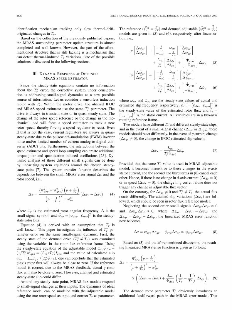
Since the steady-state equations contain no informationabout the T ∗
r error, the corrective system under considera-tion is addressing small-signal dynamics as a new possiblesource of information. Let us consider a sensorless inductionmotor with Tr. Within the motor drive, the utilized IFOCand MRAS speed estimator use the same T ∗
r parameter. Thedrive is always in transient state or in quasi-steady-state. Thechange of the rotor speed reference or the change in the me-chanical load will force a speed estimator to track a newrotor speed, thereby forcing a speed regulator to react. Evenif that is not the case, current regulators are always in quasi-steady-state due to the pulsewidth-modulation (PWM) inverternoise and/or limited number of current analog-to-digital con-verter (ADC) bits. Furthermore, the interactions between thespeed estimator and speed loop sampling can create additionaltorque jitter and quantization-induced oscillations [23]. Dy-namic analysis of these different small signals can be doneby linearizing system equations around the chosen steady-state point [7]. The system transfer function describes thedependence between the small MRAS error signal ∆ε and therotor speed, i.e.,
∆ε =
(Ψ2
dro + Ψ2qro
) (p+ 1
Tr
)(p+ 1
Tr
)2
+ ω2so
(∆ωr − ∆ωr) (4)
where ωr is the estimated rotor angular frequency, ∆ is thesmall-signal symbol, and ψro = [ψdro ψqro]T is the steady-state rotor flux.
Equation (4) is derived with an assumption that Tr iswell known. This paper investigates the influence of T ∗
r pa-rameter error on the same small-signal dynamic. First, thesteady state of the detuned drive (T ∗
r = Tr) was examinedusing the variables in the rotor flux reference frame. Usingthe steady-state equation of the adjustable model ωsoψdro −(1/T ∗
r )ψqro = (Lm/T∗r )Iqso and the value of calculated slip
ωso = LmIqso/(T ∗r ψdr0), one can conclude that the estimated
q-axis rotor flux will always be close to zero. If the referencemodel is correct, due to the MRAS feedback, actual q rotorflux will also be close to zero. However, attained and estimatedsteady-state slip could differ.
Around any steady-state point, MRAS flux models respondto small-signal changes at their inputs. The dynamics of idealreference model can be modeled with the adjustable modelusing the true rotor speed as input and correct Tr as parameter.
The reference ( ψvir = ψr) and detuned adjustable ( ψωi
r = ψr)
models are given in (5) and (6), respectively, after lineariza-tion, i.e.,
p
[∆ψdr
∆ψqr
]=
[ − 1Tr
ωs0
−ωs0 − 1Tr
] [∆ψdr
∆ψqr
]
+Lm
Tr
[∆ids
∆iqs
]+
[Ψqro
−Ψdro
]∆ωs (5)
p
[∆ψdr
∆ψqr
]=
[ − 1T∗
rωs0
−ωs0 − 1T∗
r
] [∆ψdr
∆ψqr
]
+Lm
T ∗r
[∆ids
∆iqs
]+
[Ψqr0
−Ψdr0
]∆ωs (6)
where ωso and ωso are the steady-state values of actual andestimated slip frequency, respectively; ψro = [ψdro ψqro]T isthe steady-state value of the estimated rotor flux; and is =[ids iqs]T is the stator current. All variables are in a two-axisrotating reference frame.
Two models have different Tr and different steady-state slips,and in the event of a small-signal change (∆ωr or ∆iqs), thesemodels should react differently. In the event of q current change(∆iqs = 0), the change in IFOC estimated slip value is
∆ωs =Lm
T ∗r Ψdr0
∆iqs. (7)
Provided that the same T ∗r value is used in MRAS adjustable
model, it becomes insensitive to these changes in the q-axisstator current, and the second and third terms in (6) cancel eachother. Hence, if there is no change in d-axis current (∆ids = 0)or in speed (∆ωr = 0), the change in q current alone does nottrigger any change in adjustable flux vector.
On the contrary, for ∆iqs = 0 and T ∗r = Tr, the actual flux
reacts differently. The attained slip variations (∆ωs) are fol-lowed, which should be seen in rotor flux reference model.
Neglecting the second-order small signals ∆ψdr∆εqr ≈ 0and ∆ψqr∆εdr ≈ 0, where ∆εdr = ∆ψdr − ∆ψdr and∆εqr = ∆ψqr − ∆ψqr, the linearized MRAS error functionnow becomes
∆ε = ψdro∆εqr − ψqro∆εdr ≈ ψdro∆ψqr. (8)
Based on (5) and the aforementioned discussion, the result-ing linearized MRAS error function is given as follows:
∆ε =Ψ2
dro
(p+ 1
Tr
)(p+ 1
Tr
)2
+ ω2s0
×(
(∆ωr − ∆ωr) +Lm
Ψdro
(1Tr
− 1T ∗
r
)∆iqs
). (9)
The detuned rotor parameter T ∗r obviously introduces an
additional feedforward path in the MRAS error model. That

MARCETIC AND VUKOSAVIC: SPEED-SENSORLESS AC DRIVE WITH ROTOR TIME CONSTANT PARAMETER UPDATE 2621
Fig. 2. MRAS estimator dynamics with detuned Tr parameter.
path represents the direct influence of small-signal variations inq stator current (∆iqs) on the actual rotor flux q component.The resulting dynamic model of detuned MRAS is given inFig. 2.
If the parameter error does exist, additional small-signalpropagation will take place via extra-introduced block. How-ever, the same block cancels for T ∗
r = Tr.The MRAS feedback, i.e., estimated speed ωr, is a function
of MRAS error variable. To further analyze the small-signaldynamics, that closed-loop action must be included, i.e.,
∆ε =K(p)[∆ωr +
Lm
Ψdro
(1Tr
− 1T ∗
r
)∆iqs
],
K(p) =K ′
mrasp(p+ 1
Tr
)
p
((p+ 1
Tr
)2+ ω2
so
)+K ′
mras (pKp +Ki)(p+ 1
Tr
)
(10)
where K ′mras = KmrasΨ2
dro.The filter action of K(p) depends on the MRAS gains,
which can be set for the specified dumping factor ξ and naturalangular frequency ωc [20]. The resulting MRAS closed-loopequation (11) is valid for zero slip condition only, but similarfilter action of K(p) is present for any slip frequency, i.e.,
∆ε =K ′
mrasp
p2 + 2ξωc + ω2c
[∆ωr +
Lm
Ψdro
(1Tr
− 1T ∗
r
)∆iqs
].
(11)
The MRAS error closed-loop transfer function has two inde-pendent small-signal inputs: 1) the true rotor speed and 2) the qstator current. The first part of the function describes the MRASdynamics while tracking an actual rotor speed. The second partis the function of the rotor circuit parameter error and may beused as the source for the parameter correction.
IV. PROPOSED ESTIMATION TECHNIQUE
As it is shown in the previous section, the small signal ofspeed estimator error is the function of the variations in theactual rotor speed ∆ωr and small-signal variations in the qstator current ∆iqs. Due to the limited frequency range of ma-chine’s mechanical subsystem, it is expected that ∆ωr containsnone of the significant high-frequency (HF) components. Onthe other hand, ∆iqs does, and it has a major influence on HFcomponents of the MRAS error signal.
The proposed Tr error identification mechanism uses therelationship between the first derivative of the MRAS estimator
Fig. 3. IFOC with MRAS speed estimator and Tr online identification block.
Fig. 4. Simplified block diagram of the proposed 1/Tr error estimator.
error p · ∆ε and ∆iqs, i.e.,
p∆ε =K ′
mrasp2
p2 + 2ξωc + ω2c
[∆ωr +
Lm
Ψdro
(1Tr
− 1T ∗
r
)∆iqs
].
(12)
For HF signal components, transfer function (12) has almostconstant gain and introduces insignificant signal phase shift. Ifwe also take into consideration that the mechanical rotor speedvariations can be neglected for relatively high frequencies, thecorrelation between the signals ∆iqs and p · ∆ε can be used toestimate the sign of Tr parameter error, i.e.,
p∆ε|f→∞ ≈ KmrasΨdroLm
(1Tr
− 1T ∗
r
)∆iqs. (13)
Equation (13) presents the direct link between the sign ofthe first derivation of the MRAS estimator error signal and theerror in the rotor time constant parameter. This connection isvalid only for the signal frequencies that are not influenced bythe change in the mechanical rotor speed and also are out of theMRAS closed-loop dynamic range.
Figs. 3 and 4 illustrate the 1/T ∗r update scheme that is derived
from previously presented equations. The estimation block isintegrated in IFOC structure with MRAS speed estimator, asshown in Fig. 3. Rotor parameter 1/T ∗
r is online updated, and itsnew value is used in MRAS adjustable model as well as in theIFOC slip calculator. The proposed 1/Tr error estimation block(Fig. 4) uses multiplication for the phase delay sign extraction.Phase delay sign between the iqs(t) and pε(t) signals is thenused as the 1/Tr error update signal. Integral action forces theparameter error to go to zero. The high-pass filters that areshown are necessary to cancel frequencies that are in MRASestimator dynamics range and do not depend on T ∗
r error only.The presented technique was initially verified using com-
puter simulations. The model of system in Fig. 3 using T ∗r and
a fifth-order induction motor model using Tr are created in

2622 IEEE TRANSACTIONS ON INDUSTRIAL ELECTRONICS, VOL. 54, NO. 5, OCTOBER 2007
Fig. 5. Tr identification: simulation results for 1/T ∗r = 0.5 ∗ 1/Tr .
Fig. 6. Tr identification: simulation results for 1/T ∗r = 1.5 ∗ Tr .
a Matlab/Simulink toolbox. For the parameter update methodverification purpose only, the band-limited white noise test sig-nal was added in q stator current signal. Computer simulationresults that are shown in Figs. 5 and 6 confirm the functionalityof Tr estimator block. The T ∗
r parameter was initially set toan incorrect value in both IFOC and MRAS models. Fiveseconds after the start of the simulation, T ∗
r update block wasenabled. Simulation results are presented for the rotor speedsignal at the motor model output ωr, estimated rotor speed ωr,updated parameter 1/T ∗
r , phase error signal err, and filterederror signal errf .
V. EXPERIMENTAL RESULTS
The experimental setup is presented in Fig. 7. The inductionmotor (rated power 1 kW, rated voltage 195 V, delta connec-tion, two poles, Rs = 9.1 Ω, Rr = 5.73 Ω, Lm = 0.585 H,Ls = 0.615 H, Lr = 0.615 H, σLs = 0.058 H, under ratedconditions) was loaded with MAGTROL 5410 dynamometer.
Fig. 7. Experimental setup: shaft-sensorless IFOC with Tr update block.
Three-phase voltage-source inverter was controlled digitallyusing the low-cost digital signal processor (DSP) ADMC341.Output currents were measured using three shunts placed ininverter legs and further processed using DSP analog front endwith bipolar amplifiers and ADC based on the single-slopetechnique. The rotor speed was monitored via an incrementalencoder. The motor voltage was estimated using dc bus samplesand the PWM pulses, with the deadtime and conducting voltagedrop of switching devices compensated. The PWM frequencywas set to 10 kHz, which is the same frequency used to sampleinverter leg currents and dc voltage, as well as speed estimatorsampling rate. First-order filters 1/(p+ ω1) were used insteadof pure integrators to suppress oscillations in estimated fluxand MRAS error signals. To maintain the same small-signaldynamic, current signal was processed through p/(p+ ω1)filters before being used in adjustable model and Tr estimator.To cut off the nonmodeled signal dynamics at HF, bandpassfilters were used in Tr estimator instead of high pass. TheMRAS closed-loop bandwidth was set to 100 rad/s, which isa relative low frequency range as compared with the currentloop actions.
With the feedforward parameter correction present [21], theproposed Tr error estimator was not designed to follow poten-tially fast flux transients. Consequently, the feedback was en-abled only after a stable flux level is reached, with the parametercorrective gains set to relatively low values. In practice, thegains should be set according to an application-specific signal,which is used in the estimation process. In this paper, correctivegains were set experimentally based on the output of a simplephase-sensing algorithm prompted with a specific small signaldiscovered for the motor in delta connection only.
The rotor speed and flux commands were set to constantvalues, and small signals in the q stator current were observed.After the rotating transformation has removed the fundamentalcomponent from the line current signals, the majority of the qand d stator current signals’ energy is contained within the dcand PWM frequency component. However, in the case of motorwindings in delta connection, relatively small sixth harmonicwas also noticed in line currents, creating matching oscillationin dq frame. Resulting signals for the dq stator currents are

MARCETIC AND VUKOSAVIC: SPEED-SENSORLESS AC DRIVE WITH ROTOR TIME CONSTANT PARAMETER UPDATE 2623
Fig. 8. Small signals utilized for T ∗r online correction. Stator current ids
and iqs, no load. Amplified and bandpass-filtered d/dt(err) and iqs signals.
Fig. 9. Small signals utilized for T ∗r online correction. Stator current ids
and iqs, 50% load. Amplified and bandpass-filtered d/dt(err) and iqs signals.
shown on the upper traces of Figs. 8 and 9 for no-load andload conditions, respectively. All presented signals were storedonline (1-kHz sampling rate) and then transferred via seriallink. Although there is some PWM signal aliasing with eachsignal, a form of sixth harmonic in q stator current is very clear.It is believed that deadtime that is not compensated in full,presumed windings symmetry during the motor phase currentreconstruction, and imperfect current measurement are the rootcauses for this parasite harmonic.
The discovered small signal has a relatively small amplitude(5% of nominal current value), and there was no observable os-cillation in the rotor speed. Similar small signals are acceptablefor most of the drive application, provided that their existencedoes not affect specified output speed and torque range.
Small signal can be separated and amplified using a bandpassfilter with the central frequency six times of fundamental.Lower traces show the resulting bandpass-filtered q current andfirst derivation of MRAS error signal (dashed). As it can beseen, the small signals in q current have corresponding oscil-lation in the MRAS error signal. The correlation of these twosignals can be used for Tr error estimation. Other harmonics ofMRAS error signal (first and second), which are present due to
Fig. 10. Speed control mode, 50% rated torque. (a) Measured and estimated(dashed line) speeds. (b) 1/T ∗
r parameter update. (c) Filtered phase error.
imperfect reference model, can create offset in the T ∗r result and
should be canceled with the bandpass filter.The first experimental result demonstrates the extraction of
the parameter error information from the above-described smallsignal. Fig. 10 shows the Tr identification results for the speed-controlled mode (10 Hz) and dynamometer set for 50% of thenominal load. The nominal rotor flux reference was set. Thecentral frequency of utilized bandpass filters was set to 60 Hz toextract small signal around the chosen rotor speed (600 r/min).Ten seconds after the data acquisition has started, T ∗
r was setto incorrect value, i.e., 1/T ∗
r = [0.5, 0.75, 1.25, 1.5] · (1/Tr).The figure displays the measured and estimated speeds (dashedline), normalized 1/T ∗
r trace, and filtered phase error signal.Fig. 10 demonstrates that the small signal that is present in
iqs carries enough information for rotor parameter update. Theestimator response is slow, but it seems adequate assuming thatonly the temperature-induced changes in the Tr are tracked.
The next set of experiments explores the algorithm sensi-tivity to the steady-state point change. Algorithm for the T ∗
r
update was disabled, and rotor parameter was set to 50% andthen to 150% of its nominal value. Parameter update errorsignal was observed for variety of speed transients and steadyspeed commands. Taking into account variable frequency ofthe discovered small signal, during experiments, a bandpassfilter with variable central frequency was used. Consequently,similar amount of information about the T ∗
r error was availablethroughout the whole speed range. No-load results (free shaft)are shown in Fig. 11. The estimated (dashed) and measuredspeeds are displayed on the upper trace, whereas the lowertrace shows the Tr estimation error signal. The same signalsare shown in Fig. 12 for the motor loaded with 75% of the ratedtorque.
Experimental results demonstrate that the right informationfor the parameter update holds for most of the examined op-erational points. Ones enabled, driven by the displayed errorsignal, algorithm would correct the T ∗
r , and the achieved rotor

2624 IEEE TRANSACTIONS ON INDUSTRIAL ELECTRONICS, VOL. 54, NO. 5, OCTOBER 2007
Fig. 11. Different speed transients and operating points, free shaft:1) measured and estimated (dashed line) rotor speeds and 2) filtered phase error.
Fig. 12. Different speed transients and operating points, 75% nominal load:1) measured and estimated (dashed line) rotor speeds and 2) filtered phase error.
speed would match its reference. However, the error in the fluxreference increases as the shaft approaches the speeds close tozero, particularly when load is applied. It is noticed that the lowshaft speeds together with the applied high load can lead to thesign change in Tr error signal. That would create the unstablefeedback, and estimation would fail. This is believed to be thedirect result of increased reference flux error.
As it was shown, for accurate work of the proposed Tr
identification algorithm, it is required that the MRAS referencemodel works correctly. That becomes impossible for the rotorspeeds very close to zero, and the low speed limit for the algo-rithm employment must be set. However, additional care mustbe taken while setting the parameters of the MRAS reference
Fig. 13. Speed control mode with Tr update and error in R∗s and σL∗
s :1) measured and estimated (dashed line) rotor speeds; 2) 1/T ∗
r parameterupdate trace; and 3) filtered phase error.
model. Previously demonstrated experiments were performedwith MRAS reference model using correct parameters. Theparameters R∗
s and σLs were estimated while the drive isat rest and kept constant. To role out the change of Rs, themotor temperature was controlled via external ventilation. Inaddition, in the regular time intervals, R∗
s was validated usingthe algorithm proposed in [19].
The next set of experiments explores the parameter sen-sitivity of the Tr update algorithm. Under the scope werepossible errors in the parameters R∗
s and σL∗s. Each parameter
was set to the incorrect value, and algorithm operation wasobserved. Fig. 13(a) shows sensitivity to the Rs variation.Ten seconds after the data acquisition has started, the param-eter R∗
s was artificially set to the incorrect value, i.e., R∗s =
[0.5, 0.75, 1.25, 1.5] ·Rs. Fig. 13(b) shows the influence of theσL∗
s error, i.e., σL∗s = [0.8, 0.9, 1.1, 1.2] · σLsn.
As it was expected (1), the algorithm is sensitive to an errorin other MRAS parameters. Wrong flux reference introduces aphase offset, and the parameter T ∗
r and, consequently, the speedconverge to erroneous values. While sensitivity to the Rs errordoes not change with load, sensitivity to the σLs error does,making the method almost insensitive for light loads. It canbe also noted that estimation result changes with the voltageestimation error. All of these imperfections affect the referencerotor flux value and introduce unwanted output offset that leadsto an error in the estimated Tr.
VI. CONCLUSION
This paper discusses one technique for online identificationof the rotor time constant suitable for speed-sensorless controlof induction motor. The proposed parameter correction actionis very easy to implement in the already existing MRAS-based speed estimator. Its implementation has the minimumimpact on processor power and memory needs. This paperdemonstrates that the proposed technique has the potential to

MARCETIC AND VUKOSAVIC: SPEED-SENSORLESS AC DRIVE WITH ROTOR TIME CONSTANT PARAMETER UPDATE 2625
eliminate certain drawbacks of the previously published works.It can use various small signals in stator current as an inherenttest signal for the rotor parameter update. Although the existingsmall signals vary and are application specific, these can befound in most sensorless drive applications. Moreover, theadvantage of this technique is the use of correlation betweentwo small signals, in selected frequency range, which resultcan be independent of the steady-state rotor speed and torque.However, the technique does require correct estimation of rotorflux reference vector, which is still an open issue. It is shownthat classical reference model can fail if the stator circuitparameters are wrong or if there is an error in stator voltageestimates. The listed problems increase low speed limit forpossible use of this technique. Still, better rotor flux estimationschemes are already available, and this technique with somemodest modifications may be one possible path toward robustsolution for the sensorless rotor circuit parameter update.
REFERENCES
[1] J. Holtz, “Sensorless control of induction machines—With or withoutsignal injection?” IEEE Trans. Ind. Electron., vol. 53, no. 1, pp. 7–30,Feb. 2006.
[2] C. S. Staines, C. Caruana, G. M. Asher, and M. Sumner, “Sensorlesscontrol of induction machines at zero and low frequency using zero se-quence currents,” IEEE Trans. Ind. Electron., vol. 53, no. 1, pp. 195–206,Feb. 2006.
[3] M. W. Degner and R. D. Lorenz, “Using multiple saliencies for theestimation of flux, position and velocity in AC machines,” IEEE Trans.Ind. Appl., vol. 34, no. 5, pp. 1097–1104, Sep./Oct. 1998.
[4] H. Kubota, K. Matsuse, and T. Nakano, “DSP-based speed adaptive fluxobserver of induction motor,” IEEE Trans. Ind. Appl., vol. 29, no. 2,pp. 344–348, Mar./Apr. 1993.
[5] S. Suwankawin and S. Sangwongwanich, “Design strategy of anadaptive full-order observer for speed-sensorless induction-motordrives—Tracking performance and stabilization,” IEEE Trans. Ind. Elec-tron., vol. 53, no. 1, pp. 96–119, Feb. 2006.
[6] H. Kubota and K. Matsuse, “Speed sensorless field-oriented control ofinduction motor with rotor resistance adaptation,” IEEE Trans. Ind. Appl.,vol. 30, no. 5, pp. 1219–1224, Sep./Oct. 1994.
[7] C. Schauder, “Adaptive speed identification for vector control of inductionmotors without rotational transducers,” IEEE Trans. Ind. Appl., vol. 28,no. 5, pp. 1054–1061, Sep./Oct. 1992.
[8] J. Holtz and J. Quan, “Drift- and parameter-compensated flux estimatorfor persistent zero-stator-frequency operation of sensorless-controlled in-duction motors,” IEEE Trans. Ind. Appl., vol. 39, no. 4, pp. 1052–1060,Jul./Aug. 2003.
[9] F.-Z. Peng, T. Fukao, and J. S. Lai, “Low speed performance of robustspeed identification using instantaneous reactive power for tacholess vec-tor control of induction motors,” in Proc. IEEE Ind. Appl. Soc., 1994,pp. 509–514.
[10] E. Levi, S. N. Vukosavic, and V. Vuckovic, “Study of main flux saturationeffects in field oriented induction motor drives,” in Proc. Conf. Rec. IEEEInd. Electron. Soc. Annu. Meeting, IECON, 1989, pp. 219–224.
[11] R. Krishnan and A. S. Bharadwaj, “A review of parameter sensitivity andadaptation in indirect vector controlled induction motor drive systems,”IEEE Trans. Power Electron., vol. 6, no. 4, pp. 695–703, Oct. 1991.
[12] R. Schmidt, “On-line identification of the secondary resistance of aninduction motor in the low-frequency range using a test vector,” in Proc.ICEM, Pisa, Italy, 1988, pp. 221–225.
[13] T. Rowan, R. Kerkman, and D. Laggate, “A simple on-line adaptationfor indirect field orientation of an induction machine,” IEEE Trans. Ind.Appl., vol. 27, no. 4, pp. 720–727, Jul./Aug. 1991.
[14] L. Garces, “Parameter adaptation for the speed-controlled static AC drivewith a squirrel-cage induction motor operated with variable frequencypower supply,” IEEE Trans. Ind. Appl., vol. IA-16, no. 2, pp. 173–178,Mar./Apr. 1980.
[15] S. N. Vukosavic and M. R. Stojic, “On-line tuning of the rotor timeconstant for vector-controlled induction motor in position control ap-plications,” IEEE Trans. Ind. Electron., vol. 40, no. 1, pp. 130–138,Feb. 1993.
[16] D. Telford, M. W. Dunnigan, and B. W. Williams, “Online identificationof induction machine electrical parameters for vector control loop tuning,”IEEE Trans. Ind. Electron., vol. 50, no. 2, pp. 253–261, Apr. 2003.
[17] A. B. Proca and A. Keyhani, “Sliding-mode flux observer with onlinerotor parameter estimation for induction motors,” IEEE Trans. Ind. Elec-tron., vol. 54, no. 2, pp. 716–723, Apr. 2007.
[18] M. W. Degner, J. M. Guerrero, and F. Briz, “Slip-gain estimation infield-orientation-controlled induction machines using the system transientresponse,” IEEE Trans. Ind. Appl., vol. 42, no. 3, pp. 702–711, May/Jun. 2006.
[19] K. Akatsu and A. Kawamura, “Online rotor resistance estimation usingthe transient state under speed sensorless control of induction motor,”IEEE Trans. Power Electron, vol. 15, no. 3, pp. 553–560, May 2000.
[20] H. Tajima and Y. Hori, “Speed sensorless field-orientation control of theinduction machine,” IEEE Trans. Ind. Appl., vol. 29, no. 1, pp. 175–180,Jan./Feb. 1993.
[21] E. Levi and M. Wang, “A speed estimator for high performance sensorlesscontrol of induction motors in the field weakening region,” IEEE Trans.Power Electron., vol. 17, no. 3, pp. 365–377, May 2002.
[22] E. D. Mitronikas and A. N. Safacas, “An improved sensorless vector-control method for an induction motor drive,” IEEE Trans. Ind. Electron.,vol. 52, no. 6, pp. 1660–1668, Dec. 2005.
[23] L. Ran and Y. Liao, “Sampling-induced resonance in an encoderlessvector-controlled induction motor drive,” IEEE Trans. Ind. Electron.,vol. 51, no. 3, pp. 551–557, Jun. 2004.
[24] T. Noguchi, S. Kondo, and I. Takahashi, “Field-oriented control of aninduction motor with robust on-line tuning of its parameters,” IEEE Trans.Ind. Appl., vol. 33, no. 1, pp. 35–42, Jan./Feb. 1997.
[25] B. Karanayil, M. F. Rahman, and C. Grantham, “Online stator and rotorresistance estimation scheme using artificial neural networks for vectorcontrolled speed sensorless induction motor drive,” IEEE Trans. Ind.Electron., vol. 54, no. 1, pp. 167–176, Feb. 2007.
Darko P. Marcetic (M’96) was born in Novi Sad,Serbia, in 1968. He received the B.S. degree fromthe University of Novi Sad, Novi Sad, in 1992 andthe M.S. and Ph.D. degrees from the Universityof Belgrade, Belgrade, Serbia, in 1998 and 2006,respectively.
In the period 2000–2001, he was with the motorcompany C.E.Set, Italy. In the period 2002–2006,he was with the Motor Technology Center, EmersonElectric, St. Louis, MO, and Emerson ApplianceControls, Elgin, IL, designing low-cost ac drives.
Since 2006, he has been with the Faculty of Technical Sciences, University ofNovi Sad, where he teaches a course in digital control of electrical drives. Hisinterests are in the areas of ac motor control, system modeling, and machineparameter identification.
Slobodan N. Vukosavic (M’94) was born inSarajevo, Yugoslavia, in 1962. He received the B.S.,M.S., and Ph.D. degrees from the University ofBelgrade, Belgrade, Serbia, in 1985, 1987, and 1989,respectively.
He was with Nikola Tesla Institute, Belgrade.He joined the ESCD Laboratory, Emerson Electric,St. Louis, MO, in 1988. In 1991, he was with VickersElectrics and MOOG Electric, designing motioncontrol products. He is currently a Professor inthe Faculty of Electrical Engineering, University of
Belgrade, where he serves as the Head of the Department of Power Engineering.He has published extensively and has completed more than 40 large R&D andindustrial projects.
Dr. Vukosavic is a member of the Yugoslav National Academy of Engineer-ing. His students won the IEEE IFEC contest in 2005.