speed control of induction motor using ann
83
Ann based vector control of induction motor CHAPTER - 1 INTRODUCTION 1.1 INDUCTION MOTOR Basic Construction and Operating Principle: Like most motors, an AC induction motor has a fixed outer portion, called the stator and a rotor that spins inside with a carefully engineered air gap between the two. Virtually all electrical motors use magnetic field rotation to spin their rotors. A three-phase AC induction motor is the only type where the rotating magnetic field is created naturally in the stator because of the nature of the supply. DC motors depend either on mechanical or electronic commutation to create rotating magnetic fields. A single-phase AC induction motor depends on extra electrical components to produce this rotating magnetic field. Two sets of electromagnets are formed inside any motor. In an AC induction motor, one set of electromagnets is formed in the stator because of the AC supply connected to the stator windings. The alternating nature of the supply voltage induces an Electromagnetic Force (EMF) in the rotor (just like the voltage is induced in the transformer secondary) as per Lenz’s law, thus generating another set of SBIT M.TECH Power Electronics Page 1
description
artificial neural network
Transcript of speed control of induction motor using ann

Ann based vector control of induction motor
CHAPTER -1
INTRODUCTION
1.1 INDUCTION MOTOR
Basic Construction and Operating Principle:
Like most motors, an AC induction motor has a fixed outer portion,
called the stator and a rotor that spins inside with a carefully engineered air gap
between the two. Virtually all electrical motors use magnetic field rotation to spin their
rotors.
A three-phase AC induction motor is the only type where the rotating magnetic
field is created naturally in the stator because of the nature of the supply. DC motors
depend either on mechanical or electronic commutation to create rotating magnetic
fields. A single-phase AC induction motor depends on extra electrical components to
produce this rotating magnetic field. Two sets of electromagnets are formed inside any
motor.
In an AC induction motor, one set of electromagnets is formed in the stator
because of the AC supply connected to the stator windings. The alternating nature of
the supply voltage induces an Electromagnetic Force (EMF) in the rotor (just like the
voltage is induced in the transformer secondary) as per Lenz’s law, thus generating
another set of electromagnets; hence the name – induction motor. Interaction between
the magnetic field of these electromagnets generates twisting force, or torque. As a
result, the motor rotates in the direction of the resultant torque.
STATOR
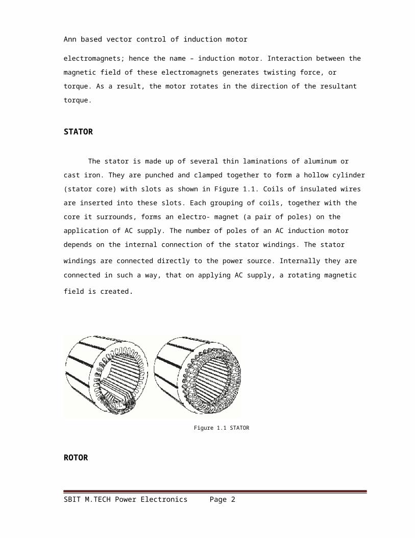
The stator is made up of several thin laminations of aluminum or cast iron. They
are punched and clamped together to form a hollow cylinder (stator core) with slots as
shown in Figure 1.1. Coils of insulated wires are inserted into these slots. Each grouping
of coils, together with the core it surrounds, forms an electro- magnet (a pair of poles)
SBIT M.TECH Power Electronics Page 1
Ann based vector control of induction motor
on the application of AC supply. The number of poles of an AC induction motor depends
on the internal connection of the stator windings. The stator windings are connected
directly to the power source. Internally they are connected in such a way, that on
applying AC supply, a rotating magnetic field is created.
Figure 1.1 STATOR
ROTOR
The rotor is made up of several thin steel laminations with evenly spaced bars,
which are made up of aluminum or copper, along the periphery. In the most popular
type of rotor (squirrel cage rotor), these bars are connected at ends mechanically and
electrically by the use of rings. Almost 90% of induction motors have squirrel cage
rotors. This is because the squirrel cage rotor has a simple and rugged construction. The
rotor consists of a cylindrical laminated core with axially placed parallel slots for
carrying the conductors. Each slot carries a copper, aluminum, or alloy bar. These rotor
bars are permanently short-circuited at both ends by means of the end rings, as shown
in Figure 1.2.
This total assembly resembles the look of a squirrel cage, which gives the rotor
its name. The rotor slots are not exactly parallel to the shaft. Instead, they are given a
skew for two main reasons. The first reason is to make the motor run quietly by reducing
magnetic hum and to decrease slot harmonics. The second reason is to help reduce the
locking tendency of the rotor. The rotor teeth tend to remain locked under the stator
teeth due to direct magnetic attraction between the two. This happens when the
numbers of stator teeth are equal to the number of rotor teeth. The rotor is mounted on
the shaft using bearings on each end; one end of the shaft is normally kept longer than
SBIT M.TECH Power Electronics Page 2

Ann based vector control of induction motor
the other for driving the load. Some motors may have an accessory shaft on the non-
driving end for mounting speed or position sensing devices. Between the stator and the
rotor, there exists an air gap, through which due to induction, the energy is transferred
from the stator to the rotor. The generated torque forces the rotor and then the load to
rotate. Regardless of the type of rotor used, the principle employed for rotation remains
the same.
Figure 1.2 Typical squirrel cage rotor
1.1 Speed of Induction Motor:
The magnetic field created in the stator rotates at a synchronous speed (NS).
The magnetic field produced in the rotor because of the induced voltage is
alternating in nature. To reduce the relative speed, with respect to the stator, the rotor
starts running in the same direction as that of the stator flux and tries to catch up with
SBIT M.TECH Power Electronics Page 3

Ann based vector control of induction motor
the rotating flux. However, in practice, the rotor never succeeds in “catching up” to the
stator field. The rotor runs slower than the speed of the stator field. This speed is called
the Base Speed (Nb). The difference between NS and Nb is called the slip. The slip varies
with the load. An increase in load will cause the rotor to slow down or increase slip. A
decrease in load will cause the rotor to speed up or decrease slip. The slip is expressed
as a percentage and can be determined with the following formula:
AC induction motors are the most common motors used in industrial motion
control systems, as well as in main powered home appliances. Simple and rugged
design, low-cost, low maintenance and direct connection to an AC power source are the
main advantages of AC induction motors. Various types of AC induction motors are
available in the market.
Different motors are suitable for different applications. Although AC induction
motors are easier to design than DC motors, the speed and the torque control in various
types of AC induction motors require a greater understanding of the design and the
characteristics of these motors. This application note discusses the basics of an AC
induction motor; the different types, their characteristics, the selection criteria for
different applications and basic control techniques.
SBIT M.TECH Power Electronics Page 4

Ann based vector control of induction motor
1.2 Types of Ac Induction Motors
Generally, induction motors are categorized based on the number of
stator windings. They are:
• Single-phase induction motor
• Three-phase induction motor
There are probably more single-phase AC induction motors in use today than the
total of all the other types put together. It is logical that the least expensive, lowest
maintenance type motor should be used most often. The single-phase AC induction
motor best fits this description. As the name suggests, this type of motor has only one
stator winding (main winding) and operates with a single-phase power supply. In all
single-phase induction motors, the rotor is the squirrel cage type.
The single-phase induction motor is not self-starting. When the motor is
connected to a single-phase power supply, the main winding carries an alternating
current. This current produces a pulsating magnetic field. Due to induction, the rotor is
energized. As the main magnetic field is pulsating, the torque necessary for the motor
rotation is not generated. This will cause the rotor to vibrate, but not to rotate. Hence,
the single phase induction motor is required to have a starting mechanism that can
provide the starting kick for the motor to rotate.
The starting mechanism of the single-phase induction motor is mainly an
additional stator winding (start/ auxiliary winding) as shown in Figure 1.3. The start
winding can have a series capacitor and/or a centrifugal switch. When the supply
voltage is applied, current in the main winding lags the supply voltage due to the main
winding impedance. At the same time, current in the start winding leads/lags the supply
voltage depending on the starting mechanism impedance. Interaction between
magnetic fields generated by the main winding and the starting mechanism generates a
resultant magnetic field rotating in one direction.
The motor starts rotating in the direction of the resultant magnetic field. Once
the motor reaches about 75% of its rated speed, a centrifugal switch disconnects the
SBIT M.TECH Power Electronics Page 5

Ann based vector control of induction motor
start winding. From this point on, the single-phase motor can maintain sufficient torque
to operate on its own. Except for special capacitor start/capacitor run types, all single-
phase motors are generally used for applications up to 3/4 hp only. Depending on the
various start techniques, single phase AC induction motors are further classified as
described in the following sections.
Figure 1.3 Single-phase AC Induction Motor with and without a start mechanism
Split-Phase AC Induction Motor
The split-phase motor is also known as an induction start/induction run motor. It
has two windings: a start and a main winding. The start winding is made with smaller
gauge wire and fewer turns, relative to the main winding to create more resistance, thus
putting the start winding’s field at a different angle than that of the main winding which
causes the motor to start rotating. The main winding, which is of a heavier wire, keeps
the motor running the rest of the time.
SBIT M.TECH Power Electronics Page 6

Ann based vector control of induction motor
figure 1.4 Typical split-phase AC Induction Motor
The starting torque is low, typically 100% to 175% of the rated torque. The motor
draws high starting current, approximately 700% to 1,000% of the rated current. The
maximum generated torque ranges from 250% to 350% of the rated torque (see Figure
1.9 for torque-speed curve).Good applications for split-phase motors include small
grinders, small fans and blowers and other low starting torque applications with power
needs from 1/20 to 1/3 hp. Avoid using this type of motor in any applications requiring
high on/off cycle rates or high torque.
Capacitor Start AC Induction Motor
This is a modified split-phase motor with a capacitor in series with the start
winding to provide a start “boost.” Like the split-phase motor, the capacitor start motor
also has a centrifugal switch which disconnects the start winding and the capacitor
when the motor reaches about 75% of the rated speed. Since the capacitor is in series
with the start circuit, it creates more starting torque, typically 200% to 400% of the
rated torque. And the starting current, usually 450% to 575% of the rated current, is
much lower than the split-phase due to the larger wire in the start circuit. Refer to Figure
1.9 for torque-speed curve. A modified version of the capacitor start motor is the
resistance start motor. In this motor type, the starting capacitor is replaced by a resistor.
The resistance start motor is used in applications where the starting torque requirement
is less than that provided by the capacitor start motor. Apart from the cost, this motor
does not offer any major advantage over the capacitor start motor.
SBIT M.TECH Power Electronics Page 7

Ann based vector control of induction motor
Figure 1.5 Typical capacitor start Induction Motor
They are used in a wide range of belt-drive applications like small conveyors, large
blowers and pumps, as well as many direct-drive or geared applications.
Permanent Split Capacitor (Capacitor Run) AC Induction Motor
A permanent split capacitor (PSC) motor has a run type capacitor permanently
connected in series with the start winding. This makes the start winding an auxiliary
winding once the motor reaches the running speed. Since the run capacitor must be
designed for continuous use, it cannot provide the starting boost of a starting capacitor.
The typical starting torque of the PSC motor is low, from 30% to 150% of the rated
torque. PSC motors have low starting current, usually less than 200% of the rated
current, making them excellent for applications with high on/off cycle rates. Refer to
Figure 1.9 for torque-speed curve. The PSC motors have several advantages. The motor
design can easily be altered for use with speed controllers. They can also be designed
for optimum efficiency and High-Power Factor (PF) at the rated load. They’re considered
to be the most reliable of the single-phase motors, mainly because no centrifugal
starting switch is required.
Figure 1.6 Typical PSC Motor
SBIT M.TECH Power Electronics Page 8

Ann based vector control of induction motor
Permanent split-capacitor motors have a wide variety of applications depending
on the design. These include fans, blowers with low starting torque needs and
intermittent cycling uses, such as adjusting mechanisms, gate operators and garage
door openers.
Capacitor Start/Capacitor Run AC Induction Motor
This motor has a start type capacitor in series with the auxiliary winding like the
capacitor start motor for high starting torque. Like a PSC motor, it also has a run type
capacitor that is in series with the auxiliary winding after the start capacitor is switched
out of the circuit. This allows high overload torque
Figure 1.7 Typical capacitor start/run Induction Motor
This type of motor can be designed for lower full-load currents and higher
efficiency (see Figure 1.9 for torque speed curve). This motor is costly due to start and
run capacitors and centrifugal switch. It is able to handle applications too demanding for
any other kind of single-phase motor. These include woodworking machinery, air
compressors, high-pressure water pumps, vacuum pumps and other high torque
applications requiring 1 to 10 hp.
Shaded-Pole AC Induction Motor
SBIT M.TECH Power Electronics Page 9

Ann based vector control of induction motor
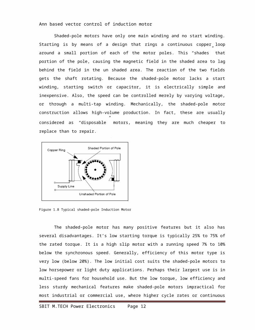
Shaded-pole motors have only one main winding and no start winding. Starting is
by means of a design that rings a continuous copper loop around a small portion of each
of the motor poles. This “shades” that portion of the pole, causing the magnetic field in
the shaded area to lag behind the field in the un shaded area. The reaction of the two
fields gets the shaft rotating. Because the shaded-pole motor lacks a start winding,
starting switch or capacitor, it is electrically simple and inexpensive. Also, the speed can
be controlled merely by varying voltage, or through a multi-tap winding. Mechanically,
the shaded-pole motor construction allows high-volume production. In fact, these are
usually considered as “disposable” motors, meaning they are much cheaper to replace
than to repair.
Figure 1.8 Typical shaded-pole Induction Motor
The shaded-pole motor has many positive features but it also has several
disadvantages. It’s low starting torque is typically 25% to 75% of the rated torque. It is a
high slip motor with a running speed 7% to 10% below the synchronous speed.
Generally, efficiency of this motor type is very low (below 20%). The low initial cost suits
the shaded-pole motors to low horsepower or light duty applications. Perhaps their
largest use is in multi-speed fans for household use. But the low torque, low efficiency
and less sturdy mechanical features make shaded-pole motors impractical for most
industrial or commercial use, where higher cycle rates or continuous duty are the norm.
Figure 1.9 shows the torque-speed curves of various kinds of single-phase AC induction
motors.
SBIT M.TECH Power Electronics Page 10

Ann based vector control of induction motor
Figure 1.9 Torque-Speed curves of different types of single-phase Induction Motors
Three-Phase AC Induction Motor
The AC induction motor is a rotating electric machine designed to operate from a
3-phase source of alternating voltage. For variable speed drives, the source is normally
an inverter that uses power switches to produce approximately sinusoidal voltages and
currents of controllable magnitude and frequency. A cross-section of a two-pole
induction motor is shown in Figure . Slots in the inner periphery of the stator
accommodate 3-phase winding a, b, c. The turns in each winding are distributed so that
a current in a stator winding produces an approximately sinusoidally-distributed flux
density around the periphery of the air gap. When three currents that are sinusoidally
varying in time, but displaced in phase by 120° from each other, flow through the three
symmetrically-placed windings, a radially-directed air gap flux density is produced that
is also sinusoidally distributed around the gap and rotates at an angular velocity equal
to the angular frequency, ws, of the stator currents.
The most common type of induction motor has a squirrel cage rotor in which
aluminum conductors or bars are cast into slots in the outer periphery of the rotor.
These conductors or bars are shorted together at both ends of the rotor by cast
aluminum end rings, which also can be shaped to act as fans. In larger induction motors,
copper or copper-alloy bars are used to fabricate the rotor cage winding. As the
SBIT M.TECH Power Electronics Page 11
Ann based vector control of induction motor
sinusoidally-distributed flux density wave produced by the stator magnetizing currents
sweeps past the rotor conductors, it generates a voltage in them. The result is a
sinusoidally-distributed set of currents in the short-circuited rotor bars. Because of the
low resistance of these shorted bars, only a small relative angular velocity, between the
angular velocity, , of the flux wave and the mechanical angular velocity of the two-pole
rotor is required to produce the necessary rotor current. The relative angular velocity, ,
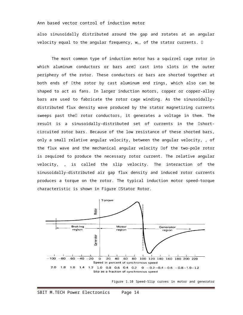
is called the slip velocity. The interaction of the sinusoidally-distributed air gap flux
density and induced rotor currents produces a torque on the rotor. The typical induction
motor speed-torque characteristic is shown in Figure Stator Rotor.
Figure 1.10 Speed–Slip curves in motor and generator regions.
Squirrel-cage AC induction motors are popular for their simple construction, low
cost per horsepower, and low maintenance (they contain no brushes, as do DC motors).
They are available in a wide range of power ratings. With field-oriented vector control
methods, AC induction motors can fully replace standard DC motors, even in high-
performance applications.
Squirrel Cage Motor
Almost 90% of the three-phase AC Induction motors are of this type. Here, the
rotor is of the squirrel cage type and it works as explained earlier. The power ratings
range from one-third to several hundred horsepower in the three-phase motors. Motors
of this type, rated one horsepower or larger, cost less and can start heavier loads than
their single-phase counterparts
SBIT M.TECH Power Electronics Page 12

Ann based vector control of induction motor
Wound-Rotor Motor
The slip-ring motor or wound-rotor motor is a variation of the squirrel cage
induction motor. While the stator is the same as that of the squirrel cage motor, it has a
set of windings on the rotor which are not short-circuited, but are terminated to a set of
slip rings. These are helpful in adding external resistors and contactors. The slip
necessary to generate the maximum torque (pull-out torque) is directly proportional to
the rotor resistance. In the slip-ring motor, the effective rotor resistance is increased by
adding external resistance through the slip rings. Thus, it is possible to get higher slip
and hence, the pull-out torque at a lower speed.
A particularly high resistance can result in the pull-out torque occurring at almost
zero speed, providing a very high pull-out torque at a low starting current. As the motor
accelerates, the value of the resistance can be reduced, altering the motor
characteristic to suit the load requirement. Once the motor reaches the base speed,
external resistors are removed from the rotor. This means that now the motor is working
as the standard induction motor. This motor type is ideal for very high inertia loads,
where it is required to generate the pull-out torque at almost zero speed and accelerate
to full speed in the minimum time with minimum current draw.
Figure 1.11 Typical wound rotor Induction Motor
The downside of the slip ring motor is that slip rings and brush assemblies need
regular maintenance, which is a cost not applicable to the standard cage motor. If the
rotor windings are shorted and a start is attempted (i.e., the motor is converted to a
standard induction motor), it will exhibit an extremely high locked rotor current –
typically as high as 1400% and a very low locked rotor torque, perhaps as low as 60%.
In most applications, this is not an option. Modifying the speed torque curve by altering
SBIT M.TECH Power Electronics Page 13
Ann based vector control of induction motor
the rotor resistors, the speed at which the motor will drive a particular load can be
altered.
At full load, you can reduce the speed effectively to about 50% of the motor
synchronous speed, particularly when driving variable torque/variable speed loads, such
as printing presses or compressors. Reducing the speed below 50% results in very low
efficiency due to higher power dissipation in the rotor resistances. This type of motor is
used in applications for driving variable torque/ variable speed loads, such as in printing
presses, compressors, conveyer belts, hoists and elevators.
Torque Equation Governing Motor Operation
The motor load system can be described by a fundamental torque equation.
For drives with constant inertia, (dJ/dt) = 0. Therefore, the equation would be:
This shows that the torque developed by the motor is counter balanced by a load
torque, Tl and a dynamic torque, J (dm/dt). The torque component, J (d/dt), is called the
dynamic torque because it is present only during the transient operations. The drive
accelerates or decelerates depending on whether T is greater or less than T l. During
acceleration, the motor should supply not only the load torque, but an additional torque
component, J(dm/dt), in order to overcome the drive inertia. In drives with large inertia,
such as electric trains, the motor torque must exceed the load torque by a large amount
in order to get adequate acceleration. In drives requiring fast transient response, the
motor torque should be maintained at the highest value and the motor load system
SBIT M.TECH Power Electronics Page 14

Ann based vector control of induction motor
should be designed with the lowest possible inertia. The energy associated with the
dynamic torque, J (dm/dt), is stored in the form of kinetic energy (KE) given by, J.During
deceleration, the dynamic torque, J (dm/dt), has a negative sign. Therefore, it assists the
motor developed torque T and maintains the drive motion by extracting energy from the
stored kinetic energy. To summarize, in order to get steady state rotation of the motor,
the torque developed by the motor (T) should always be equal to the torque
requirement of the load (Tl). The torque-speed curve of the typical three-phase
induction motor is shown in fig 1.12
Figure 1.12 Torque – Speed curve of Three-phase Induction Motor
1.3 Advantages of induction motors:
In the past, DC motors were used extensively in areas where variable-speed
operations were required. DC motors have certain disadvantages, however, which are
due to the existence of the commutator and the brushes which makes the motor more
bulky, costly and heavy.
These problems could be overcome by application of AC motors. AC motors have
simpler and more rugged structure, higher maintainability and economy than DC
motors. They are also robust and immune to heavy loading. The speed of the induction
motor has to be controlled and so different types of controllers are used to obtain the
SBIT M.TECH Power Electronics Page 15

Ann based vector control of induction motor
desired speed.
1.4 Applications of Induction Motors:
1. For Adjustable speed drives.
2. In automobile purposes.
3. In Industry applications.
4. Variable frequency drives.
5. Electromagnetic actuator control using DSP
6. Embedded solutions
7. Energy efficient solutions
8. Home Appliances
9. Refrigerators, freezers, Dryers, dishwashers, washing machines
10. Magnetic card strip encoders and readers
11. Motion control with wireless sensors, robot manipulator, robot arm and etc.
With the emergence of digital signal processors (DSP) and microcontrollers (MCU)
combined with new power electronic devices, closed-loop control systems employing
vector, direct torque and adaptive controls methods can be used to expand the low cost
capabilities of AC motors into many new applications.
SBIT M.TECH Power Electronics Page 16

Ann based vector control of induction motor
CHAPTER - 2
NEURAL NETWORKS
2.1 INTRODUCTION
Neural networks are composed of simple elements operating in parallel. These
elements are inspired by biological nervous systems. As in nature, the network function
is determined largely by the connections between elements. Neural network is trained
to perform a particular function by adjusting the values of the connections (weights)
between elements. Commonly Neural Networks are adjusted, or trained, so that a
particular input leads to a specific target output. There, the network is adjusted, based
on a comparison of the output and the target, until the network output matches the
target. Typically many such input/target pairs are used, in this supervised learning, to
train a network
SBIT M.TECH Power Electronics Page 17

Ann based vector control of induction motor
Figure 2.1 Block diagram of Neural Network
Batch training of a network proceeds by making weight and bias changes based
on an entire set (batch) of input vectors. Incremental training changes the weights and
biases of a network as needed after presentation of each individual input vector.
Incremental training is sometimes referred to as "on line" or "adaptive" training. Neural
networks have been trained to perform complex functions in various fields of application
including pattern recognition, identification, classification, speech, and vision and
control systems. Today neural networks can be trained to solve problems that are
difficult for conventional computers or human beings.
The supervised training methods are commonly used, but other networks can be
obtained from unsupervised training techniques or from direct design methods.
Unsupervised networks can be used, for instance, to identify groups of data. Certain
kinds of linear networks and Hopfield networks are designed directly.
In summary, there are a variety of kinds of design and learning techniques that enrich
the choices that a user can make.
Simple Neuron
A neuron with a single scalar input and no bias appears on the left below.
Figure 2.2 Connection diagram
The scalar input p is transmitted through a connection that multiplies its strength
by the scalar weight w, to form the product wp, again a scalar. Here the weighted input
SBIT M.TECH Power Electronics Page 18

Ann based vector control of induction motor
wp is the only argument of the transfer function f, which produces the scalar output a.
The neuron on the right has a scalar bias, b. You may view the bias as simply being
added to the product wp as shown by the summing junction or as shifting the function f
to the left by an amount b. The bias is much like a weight, except that it has a constant
input of 1.
The transfer function net input n, again a scalar, is the sum of the weighted input
wp and the bias b. This sum is the argument of the transfer function f. (Radial Basis
Networks discusses a different way to form the net input n.) Here f is a transfer function,
typically a step function or a sigmoid function, which takes the argument n and
produces the output a. Examples of various transfer functions are given in the next
section. Note that w and b are both adjustable scalar parameters of the neuron. The
central idea of neural networks is that such parameters can be adjusted so that the
network exhibits some desired or interesting behavior. Thus, we can train the network to
do a particular job by adjusting the weight or bias parameters, or perhaps the network
itself will adjust these parameters to achieve some desired end.
All of the neurons in this toolbox have provision for a bias, and a bias is used in
many of our examples and will be assumed in most of this toolbox. However, you may
omit a bias in a neuron if you want. As previously noted, the bias b is an adjustable
(scalar) parameter of the neuron. It is not an input. However, the constant 1 that drives
the bias is an input and must be treated as such when considering the linear
dependence of input vectors in Linear Filters.
Transfer Functions
The behaviour of an ANN (Artificial Neural Network) depends on both the weights
and the input-output function (transfer function) that is specified for the units. This
function typically falls into one of three categories:
Linear (or ramp)
Threshold
Sigmoid
SBIT M.TECH Power Electronics Page 19

Ann based vector control of induction motor
For linear units, the output activity is proportional to the total weighted output.
For threshold units, the output are set at one of two levels, depending on
whether the total input is greater than or less than some threshold value.
For sigmoid units, the output varies continuously but not linearly as the input
changes. Sigmoid units bear a greater resemblance to real neurons than do linear or
threshold units, but all three must be considered rough approximations.
2.2 Architecture of neural networks
Feed-forward networks
Feed-forward ANNs allow signals to travel one way only; from input to output.
There is no feedback (loops) i.e. the output of any layer does not affect that same layer.
Feed-forward ANNs tend to be straight forward networks that associate inputs with
outputs. They are extensively used in pattern recognition. This type of organisation is
also referred to as bottom-up or top-down.
Feedback networks
Feedback networks can have signals travelling in both directions by introducing
loops in the network. Feedback networks are very powerful and can get extremely
complicated. Feedback networks are dynamic; their 'state' is changing continuously
until they reach an equilibrium point. They remain at the equilibrium point until the
input changes and a new equilibrium needs to be found. Feedback architectures are
also referred to as interactive or recurrent, although the latter term is often used to
denote feedback connections in single-layer organizations.
SBIT M.TECH Power Electronics Page 20

Ann based vector control of induction motor
Figure 2.3 An example of a simple feed forward Network
Figure 2.4 An example of a complicated Network
Network layers
SBIT M.TECH Power Electronics Page 21

Ann based vector control of induction motor
The commonest type of artificial neural network consists of three groups, or layers,
of units: a layer of "input" units is connected to a layer of "hidden" units, which is
connected to a layer of "output" units.
The activity of the input units represents the raw information that is fed into the
network.
The activity of each hidden unit is determined by the activities of the input units
and the weights on the connections between the input and the hidden units.
The behavior of the output units depends on the activity of the hidden units and
the weights between the hidden and output units.
This simple type of network is interesting because the hidden units are free to construct
their own representations of the input. The weights between the input and hidden units
determine when each hidden unit is active, and so by modifying these weights, a hidden
unit can choose what it represents.
Perceptrons
The most influential work on neural nets in the 60's went under the heading of
'perceptrons' a term coined by Frank Rosenblatt. The perceptron (figure 4.4) turns out
to be an MCP model (neuron with weighted inputs) with some additional, fixed, pre--
processing. Units labelled A1, A2, Aj, Ap are called association units and their task is to
extract specific, localised featured from the input images. Perceptrons mimic the basic
idea behind the mammalian visual system. They were mainly used in pattern
recognition even though their capabilities extended a lot more.
SBIT M.TECH Power Electronics Page 22

Ann based vector control of induction motor
Figure 2.5 Perceptron model
Backpropagation
Backpropagation was created by generalizing the Widrow-Hoff learning rule to
multiple-layer networks and nonlinear differentiable transfer functions. Input vectors
and the corresponding target vectors are used to train a network until it can
approximate a function, associate input vectors with specific output vectors, or classify
input.
Networks with biases, a sigmoid layer, and a linear output layer are capable of
approximating any function with a finite number of discontinuities. Standard back
propagation is a gradient descent algorithm, as is the Widrow-Hoff learning rule, in
which the network weights are moved along the negative of the gradient of the
performance function. The term back propagation refers to the manner in which the
gradient is computed for nonlinear multilayer networks. There are a number of
variations on the basic algorithm that are based on other standard optimization
techniques, such as conjugate gradient and Newton methods.
The Neural Network Toolbox implements a number of these variations. This
chapter explains how to use each of these routines and discusses the advantages and
disadvantages of each. Properly trained back propagation networks tend to give
reasonable answers when presented with inputs that they have never seen. Typically, a
new input leads to an output similar to the correct output for input vectors used in
training that are similar to the new input being presented. This generalization property
makes it possible to train a network on a representative set of input/target pairs and get
good results without training the network on all possible input/output pairs.
There are two features of the Neural Network Toolbox that are designed to
improve network generalization - regularization and early stopping. These features and
their use are discussed later in this chapter. This chapter also discusses preprocessing
and post processing techniques, which can improve the efficiency of network training.
Steps for ANN:
1.Creating a Network (newff):
SBIT M.TECH Power Electronics Page 23

Ann based vector control of induction motor
2. Initializing Weights (init).
3. Simulation (sim):
4. Training
2.3 Applications of neural networks
Neural networks have broad applicability to real world business problems. In fact,
they have already been successfully applied in many industries.
Since neural networks are best at identifying patterns or trends in data, they are
well suited for prediction or forecasting needs including:
Sales forecasting
Industrial process control
Customer research
Data validation
Risk management
Target marketing
But to give you some more specific examples; ANN are also used in the following
specific paradigms: recognition of speakers in communications; diagnosis of hepatitis;
recovery of telecommunications from faulty software; interpretation of multimeaning,
three-dimensional object recognition; hand-written word recognition; and facial
recognition.
Neural networks in medicine
Artificial Neural Networks (ANN) are currently a 'hot' research area in medicine
and it is believed that they will receive extensive application to biomedical systems in
the next few years. At the moment, the research is mostly on modelling parts of the
SBIT M.TECH Power Electronics Page 24

Ann based vector control of induction motor
human body and recognising diseases from various scans (e.g. cardiograms, CAT scans,
ultrasonic scans, etc.).
Neural networks are ideal in recognising diseases using scans since there is no
need to provide a specific algorithm on how to identify the disease. Neural networks
learn by example so the details of how to recognise the disease are not needed. What is
needed is a set of examples that are representative of all the variations of the disease.
The quantity of examples is not as important as the 'quantity'. The examples need to be
selected very carefully if the system is to perform reliably and efficiently.
Modelling and Diagnosing the Cardiovascular System
Neural Networks are used experimentally to model the human cardiovascular
system. Diagnosis can be achieved by building a model of the cardiovascular system of
an individual and comparing it with the real time physiological measurements taken
from the patient. If this routine is carried out regularly, potential harmful medical
conditions can be detected at an early stage and thus make the process of combating
the disease much easier.
A model of an individual's cardiovascular system must mimic the relationship
among physiological variables (i.e., heart rate, systolic and diastolic blood pressures,
and breathing rate) at different physical activity levels. If a model is adapted to an
individual, then it becomes a model of the physical condition of that individual. The
simulator will have to be able to adapt to the features of any individual without the
supervision of an expert. This calls for a neural network.
Another reason that justifies the use of ANN technology, is the ability of ANNs to
provide sensor fusion which is the combining of values from several different sensors.
Sensor fusion enables the ANNs to learn complex relationships among the individual
sensor values, which would otherwise be lost if the values were individually analysed. In
medical modelling and diagnosis, this implies that even though each sensor in a set may
be sensitive only to a specific physiological variable, ANNs are capable of detecting
complex medical conditions by fusing the data from the individual biomedical sensors.
Electronic noses
ANNs are used experimentally to implement electronic noses. Electronic
noses have several potential applications in telemedicine. Telemedicine is the practice
SBIT M.TECH Power Electronics Page 25

Ann based vector control of induction motor
of medicine over long distances via a communication link. The electronic nose would
identify odours in the remote surgical environment. These identified odours would then
be electronically transmitted to another site where a door generation system would
recreate them. Because the sense of smell can be an important sense to the surgeon,
telesmell would enhance telepresent surgery. For more information on telemedicine and
telepresent surgery click here.
Instant Physician
An application developed in the mid-1980s called the "instant physician"
trained an autoassociative memory neural network to store a large number of medical
records, each of which includes information on symptoms, diagnosis, and treatment for
a particular case. After training, the net can be presented with input consisting of a set
of symptoms; it will then find the full stored pattern that represents the "best" diagnosis
and treatment
Neural Networks in business
Business is a diverted field with several general areas of specialization such as
accounting or financial analysis. Almost any neural network application would fit into
one business area or financial analysis
There is some potential for using neural networks for business purposes,
including resource allocation and scheduling. There is also a strong potential for using
neural networks for database mining, that is, searching for patterns implicit within the
explicitly stored information in databases. Most of the funded work in this area is
classified as proprietary. Thus, it is not possible to report on the full extent of the work
SBIT M.TECH Power Electronics Page 26

Ann based vector control of induction motor
going on. Most work is applying neural networks, such as the Hopfield-Tank network for
optimization and scheduling.
Marketing
There is a marketing application which has been integrated with a neural
network system. The Airline Marketing Tactician (a trademark abbreviated as AMT) is a
computer system made of various intelligent technologies including expert systems. A
feedforward neural network is integrated with the AMT and was trained using back-
propagation to assist the marketing control of airline seat allocations. The adaptive
neural approach was amenable to rule expression. Additionaly, the application's
environment changed rapidly and constantly, which required a continuously adaptive
solution. The system is used to monitor and recommend booking advice for each
departure. Such information has a direct impact on the profitability of an airline and can
provide a technological advantage for users of the system. [Hutchison & Stephens,
1987]
While it is significant that neural networks have been applied to this problem, it
is also important to see that this intelligent technology can be integrated with expert
systems and other approaches to make a functional system. Neural networks were used
to discover the influence of undefined interactions by the various variables. While these
interactions were not defined, they were used by the neural system to develop useful
conclusions. It is also noteworthy to see that neural networks can influence the bottom
line.
Credit Evaluation
The HNC company, founded by Robert Hecht-Nielsen, has developed several
neural network applications. One of them is the Credit Scoring system which increase
the profitability of the existing model up to 27%. The HNC neural systems were also
applied to mortgage screening. A neural network automated mortgage insurance
underwritting system was developed by the Nestor Company. This system was trained
with 5048 applications of which 2597 were certified. The data related to property and
borrower qualifications. In a conservative mode the system agreed on the underwritters
on 97% of the cases. In the liberal model the system agreed 84% of the cases. This is
SBIT M.TECH Power Electronics Page 27

Ann based vector control of induction motor
system run on an Apollo DN3000 and used 250K memory while processing a case file in
approximately 1 sec.
CHAPTER - 3
SPEED CONTROL OF INDUCTION MOTORS
3.1 CONVENTIONAL TYPES OF SPEED CONTROL
Methods of speed control.
The speed of a driven load often needs to run at a speed that varies according to
the operation it is performing. The speed in some cases such as pumping may need to
change dynamically to suit the conditions, and in other cases may only change with a
change in process. Electric motors and coupling combinations used for altering the
speed will behave as either a "Speed Source" or a "Torque Source". The "Speed Source"
is one where the driven load is driven at a constant speed independent of load torque. A
"Torque Source" is one where the driven load is driven by a constant torque, and the
speed alters to the point where the torque of the driven load equals the torque
delivered by the motor. Closed loop controllers employ a feedback loop to convert a
"Torque Source" into a "Speed Source" controller.
SBIT M.TECH Power Electronics Page 28

Ann based vector control of induction motor
Mechanical.
There are a number of methods of mechanically varying the speed of the driven
load when the driving motor is operating at a constant speed. These are typically:
Belt DriveChain DriveGear BoxIdler wheel drive
All of these methods exhibit similar characteristics whereby the motor operates
at a constant speed and the coupling ratio alters the speed of the driven load.
Increasing the torque load on the output of the coupling device, will increase the torque
load on the motor. As the motor is operating at full voltage and rated frequency, it is
capable of delivering grated output power. There is some power loss in the coupling
device resulting in a reduction of overall efficiency. The maximum achievable efficiency
is dependent on the design of the coupling device and sometimes the way it is set up.
(e.g. belt tension, no of belts, type of belts etc.)Most mechanical coupling devices are
constant ratio devices and consequently the load can only be run at one or more
predetermined speeds. There are some mechanical methods that do allow for a dynamic
speed variation but these are less common and more expensive.
Mechanical speed change methods obey the 'Constant Power Law' where the
total power input is equal to the total power output. As the motor is capable of
delivering rated power output, the output power capacity of the combination of motor
and coupling device (provided the coupling device is appropriately rated) is the rated
motor output power minus the loss power of the coupling device.
Torque 'T' is a Constant 'K' times the Power 'P' divided by the speed 'N'.
T = K x P / N
Therefore for an ideal lossless system, the torque at the output of the coupling
device is increased by the coupling ration for a reduced speed, or reduced by the
coupling ratio for an increased speed.
SBIT M.TECH Power Electronics Page 29

Ann based vector control of induction motor
Magnetic.
There are two main methods of magnetically varying the speed of the driven
load when the driving motor is operating at a constant speed. These are:
These methods use a coupling method between the motor and the driven load
which operates on induced magnetic forces. The eddy current coupling is quite
commonly employed, and is easily controlled by varying the bias on one of the
windings. In operation, it is not unlike an induction motor, with one set of poles driven
by the driving motor, hence operating at the speed of the driving motor.
The second set of poles are coupled to the driven load, and rotate at the same
speed as the driven load. One set of poles comprises a shorted winding in the same
manner as the rotor of an induction motor, while the other set of poles is connected to a
controlled D.C. current source. When the machine is in operation, there is a difference in
speed between the two sets of poles, and consequently there is a current induced in the
shorted winding. This current establishes a rotating field and torque is developed in the
same way as an induction motor. The coupling torque is controlled by the D.C.
excitation current. This method of coupling is essentially a torque coupling with slip
power losses in the coupling.
Hydraulic.
There are two main methods of hydraulically varying the speed of the driven load
when the driving motor is operating at a constant speed. These are:
Hydraulic pump and motorFluid Coupling
The fluid coupling is a torque coupling whereby the input torque is equal to the
SBIT M.TECH Power Electronics Page 30
Eddy Current Drive
Magnetic Coupling

Ann based vector control of induction motor
output torque. This type of coupling suffers from very high slip losses, and is used
primarily as a torque limited coupling during start with a typical slip during run of 5%.
The constant power law still applies, but the power in the driven load reduces with
speed. The difference between the input power and the output power is loss power
dissipated in the coupling. In an extreme case, if the load is locked (stationary) and the
motor is delivering full torque to the load via a fluid coupling, the load will be doing no
work and hence absorbing no power, with the motor operating at full speed and full
torque, the full output power of the motor is dissipated in the coupling. In most
applications, the torque requirement of the load at reduced speed is much reduced, so
the power dissipation is much less than the motor rating. In the case of a hydraulic
pump and motor, the induction motor operates at a fixed speed, and drives a hydraulic
pump which in turn drives a hydraulic motor. In many respects, this behaves in a
manner similar to a gear box in that the hydraulic system transfers power to the load.
The torque will be higher at the load than at the motor for a load running slower than
the motor.
Electrical.
There are a number of methods of electrically varying the speed of the driven
load and driving motor.
These are:
D.C. MotorUniversal MotorSchrage motorHigh Slip Motor (Fan Motor)Slip Ring MotorVariable Frequency Drive and Induction Motor
The D.C. motor
The DC Motor was traditionally a very common means of controlling process
speed. It is essentially a "Torque Source" controller and is usually used with a
SBIT M.TECH Power Electronics Page 31

Ann based vector control of induction motor
tachogenerator feedback to control the speed of the driven load. The D.C. motor
consists of a field winding and an armature. The armature is fed via brushes on a
commutator. The D.C. motor is available in two main formats, Series wound and shunt
wound. Small D.C.
Motors are often series wound giving the advantage of improved starting torque.
With a series wound D.C. motor, speed control is achieved by regulating the voltage
applied to the motor. All the motor current passes through the voltage regulator.
A shunt wound motor has separated field and armature windings. The torque
output of the motor is varied by controlling the excitation on the armature winding while
maintaining full voltage D.C. on the field.
The voltage regulator only passes the current to the field winding, dissipating
much less power than in the case of the shunt wound motor.
D.C. motors are a torque source, and so are able to operate well under high transient
load conditions. At low speed, the D.C. motor is able to deliver a high torque.
The universal motor
The Universal Motor is a motor with a wound armature and a wound stator. The
armature is fed via brushes on a commutator, and is essentially the same as a D.C.
motor. The universal motor will operate off a single phase A.C. supply and accelerates
until the load torque equals the output torque. Domestic appliances, such as vacuum
cleaners, and small hand tools such as electric drills use this technology. The speed is
changed by reducing the voltage applied to the motor. This is often a triac based
voltage controller similar to a domestic light dimmer.
A Schrage motor
The Schrage Motor is a very special motor with a brush/commutator fed rotor
and a slip ring fed rotor and a wound stator, and due to the way it is constructed is able
SBIT M.TECH Power Electronics Page 32

Ann based vector control of induction motor
to be speed controlled by variation of the position of the brushes relative to the field
windings. The rotor has two windings, one of which is driven by the commutator/brush
assembly and the other is driven by means of slip rings. These motors are usually of
European origin and found of some of the older machines imported for specialised
applications such as carpet making.
High Slip Induction Motor
An induction motor with a high rotor resistance is a high slip motor and is often
referred to as a fan motor or a type F motor. The torque capacity of this motor is high at
low speeds and low at synchronous speed. By reducing the voltage applied to the Type
F motor, the available torque is reduced and consequently, when coupled to a fan load,
the speed reduces. A type F motor has a high power dissipation in the rotor and is only
useful for smaller single phase and three phase machines. The actual speed is
dependant on the stator voltage, motor characteristics and load torque. Voltage
controllers are either transformers, variacs or SCR based solid state controllers.
Slip ring motors
Slip Ring Motors are induction motors with a wound rotor with the rotor winding
accessible via slip rings. Changing the value of external resistance connected in series
with the rotor windings, will vary the torque curve of the motor. With a high value of
resistance in the rotor circuit, the slip ring motor will behave like a type F motor. With
the slip ring motor, the stator voltage is held constant at line voltage, and the rotor
resistance is varied to alter the torque capacity of the motor and hence the speed. This
type of speed control is used on large machines because the rotor power dissipated is
external to the motor. Typical applications are in hoisting and dragline type machines
associated with dredging machines.
Variable frequency drives
The speed of standard induction motors can be controlled by variation of the
frequency of the voltage applied to the motor. Due to flux saturation problems with
SBIT M.TECH Power Electronics Page 33

Ann based vector control of induction motor
induction motors, the voltage applied to the motor must alter with the frequency. The
induction motor is a pseudo synchronous machine and so behaves as a speed source.
The running speed is set by the frequency applied to it and is independent of load
torque provided the motor is not over loaded.
Pulse width modulation
Pulse-width modulation (PWM) of a signal or power source involves the
modulation of its duty cycle, to either convey information over a communications
channel or control the a PWM is also often used to control the supply of electrical power
to another device such as in speed control of electric motors, volume control of Class D
audio amplifiers or brightness control of light sources and many other power electronics
applications. For example, light dimmers for home use employ a specific type of PWM
control. Home use light dimmers typically include electronic circuitry which suppresses
current flow during defined portions of each cycle of the AC line voltage. Adjusting the
brightness of light emitted by a light source is then merely a matter of setting at what
voltage (or phase) in the AC cycle the dimmer begins to provide electrical current to the
light source (e.g. by using an electronic switch such as a triac).
In this case the PWM duty cycle is defined by the frequency of the AC line
voltage (50 Hz or 60 Hz depending on the country). These rather simple types of
dimmers can be effectively used with inert (or relatively slow reacting) light sources
such as incandescent lamps, for example, for which the additional modulation in
supplied electrical energy which is caused by the dimmer causes only negligible
additional fluctuations in the emitted light. Some other types of light sources such as
light-emitting diodes (LEDs), however, turn on and off extremely rapidly and would
perceivably flicker if supplied with low frequency drive voltages. Perceivable flicker
effects from such rapid response light sources can be reduced by increasing the PWM
frequency. If the light fluctuations are sufficiently rapid, the human visual system can no
longer resolve them and the eye perceives the time average intensity without flicker
mount of power sent to a load.
3.2 VFD speed control Techniques
Various speed control techniques implemented by modern-age VFD are mainly
SBIT M.TECH Power Electronics Page 34

Ann based vector control of induction motor
classified in the following three categories:
• Scalar Control (V/f Control)
• Vector Control (Indirect Torque Control)
• Direct Torque Control (DTC)
Scalar Control
In this type of control, the motor is fed with variable frequency signals generated
by the PWM control from an inverter using the feature rich PIC micro microcontroller.
Here, the V/f ratio is maintained constant in order to get constant torque over the entire
operating range. Since only magnitudes of the input variables – frequency and voltage –
are controlled, this is known as “scalar control”. Generally, the drives with such a control
are without any feedback devices (open loop control). Hence, a control of this type
offers low cost and is an easy to implement solution. In such controls, very little
knowledge of the motor is required for frequency control.
Thus, this control is widely used. A disadvantage of such a control is that the
torque developed is load dependent as it is not controlled directly. Also, the transient
response of such a control is not fast due to the predefined switching pattern of the
inverter. However, if there is a continuous block to the rotor rotation, it will lead to
heating of the motor regardless of implementation of the overcurrent control loop. By
adding a speed/position sensor, the problem relating to the blocked rotor and the load
dependent speed can be overcome. However, this will add to the system cost, size and
complexity. There are a number of ways to implement scalar control. The popular
schemes are described in the following sections.
Vector Control
This control is also known as the “field oriented control”, “flux oriented control”
or “indirect torque control”. Using field orientation (Clarke-Park transformation), three-
phase current vectors are converted to a two-dimensional rotating reference frame (d-q)
from a three-dimensional stationary reference frame. The “d” component represents the
flux producing component of the stator current and the “q” component represents the
torque producing component. These two decoupled components can be independently
controlled by passing though separate PI controllers.
SBIT M.TECH Power Electronics Page 35

Ann based vector control of induction motor
The outputs of the PI controllers are transformed back to the three-dimensional
stationary reference plane using the inverse of the Clarke-Park transformation. The
corresponding switching pattern is pulse width modulated and implemented using the
SVM.
This control simulates a separately exited DC motor model, which provides an
excellent torque-speed curve.
The transformation from the stationary reference frame to the rotating reference
frame is done and controlled (stator flux linkage, rotor flux linkage or magnetizing flux
linkage). In general, there exists three possibilities for such selection and hence, three
different vector controls. They are:
• Stator flux oriented control
• Rotor flux oriented control
• Magnetizing flux oriented control
As the torque producing component in this type of control is controlled only after
transformation is done and is not the main input reference, such control is known as
“indirect torque control”. The most challenging and ultimately, the limiting feature of
the field orientation, is the method whereby the flux angle is measured or estimated.
Depending on the method of measurement, the vector control is divided into two
subcategories: direct and indirect vector control. In direct vector control, the flux
measurement is done by using the flux sensing coils or the Hall devices. This adds to
additional hardware cost and in addition, measurement is not highly accurate.
Therefore, this method is not a very good control technique. The more common method
is indirect vector control. In this method, the flux angle is not measured directly, but is
estimated from the equivalent circuit model and from measurements of the rotor speed,
the stator current and the voltage. One common technique for estimating the rotor flux
is based on the slip relation. This requires the measurement of the rotor position and the
stator current. With current and position sensors, this method performs reasonably well
over the entire speed range.
The most high-performance VFDs in operation today employ indirect field
SBIT M.TECH Power Electronics Page 36

Ann based vector control of induction motor
orientation based on the slip relation. The main disadvantage of this method is the need
of the rotor position information using the shaft mounted encoder. This means additional
wiring and component cost. This increases the size of the motor. When the drive and the
motor are far apart, the additional wiring poses a challenge. To overcome the
sensor/encoder problem, today’s main research focus is in the area of a sensor less
approach. The advantages of the vector control are to better the torque response
compared to the scalar control, full-load torque close to zero speed, accurate speed
control and performance approaching DC drive, among others. But this requires a
complex algorithm for speed calculation in real-time. Due to feedback devices, this
control becomes costly compared to the scalar control.
Direct Torque Control (DTC)
The difference between the traditional vector control and the DTC is that the DTC
has no fixed switching pattern. The DTC switches the inverter according to the load
needs. Due to elimination of the fixed switching pattern (characteristic of the vector and
the scalar control), the DTC response is extremely fast during the instant load changes.
Although the speed accuracy up to 0.5% is ensured with this complex technology, it
eliminates the requirement of any feedback device. The block diagram of the DTC
implementation is shown in Figure 24. The heart of this technology is its adaptive motor
model. This model is based on the mathematical expressions of basic motor theory. This
model requires information about the various motor parameters, like stator resistance,
mutual inductance, saturation coefficiency, etc. The algorithm captures all these details
at the start from the motor without rotating the motor. But rotating the motor for a few
seconds helps in the tuning of the model. The better the tuning, the higher the accuracy
of speed and torque control. With the DC bus voltage, the line currents and the present
switch position as inputs, the model calculates actual flux and torque of the motor.
These values are fed to two-level comparators of the torque and flux, respectively. The
output of these comparators is the torque and flux reference signals for the optimal
switch selection table. Selected switch position is given to the inverter without any
modulation, which means faster response time. The external speed set reference signal
is decoded to generate the torque and flux reference. Thus, in the DTC, the motor
torque and flux become direct controlled variables and hence, the name – Direct Torque
Control. The advantage of this technology is the fastest response time, elimination of
feedback devices, reduced mechanical failure, performance nearly the same as the DC
machine without feedback, etc. The disadvantage is due to the inherent hysteresis of
the comparator, higher torque and flux ripple exist. Since switching is not done at a very
SBIT M.TECH Power Electronics Page 37

Ann based vector control of induction motor
high frequency, the low order harmonics increases. It is believed that the DTC can be
implemented using an Artificial Intelligence model instead of the model based on
mathematical equations. This will help in better tuning of the model and less
dependence on the motor parameters.
3.3 VECTOR CONTROL of induction motor
The AC induction motor (ACIM) is the workhorse of industrial and residential
motor applications due to its simple construction and durability. These motors have no
brushes to wear out or magnets to add to the cost. The rotor assembly is a simple steel
cage. ACIM’s are designed to operate at a constant input voltage and frequency, but you
can effectively control an ACIM in an open loop variable speed application if the
frequency of the motor input voltage is varied. If the motor is not mechanically
overloaded, the motor will operate at a speed that is roughly proportional to the input
frequency. As you decrease the frequency of the drive voltage, you also need to
decrease the amplitude by a proportional amount. Otherwise, the motor will consume
excessive current at low input frequencies. This control method is called Volts-Hertz
control. In practice, a custom Volts-Hertz profile is developed that ensures the motor
operates correctly at any speed setting. This profile can take the form of a look-up table
or can be calculated during run time. Often, a slope variable is used in the application
that defines a linear relationship between drive frequency and voltage at any operating
point. The Volts-Hertz control method can be used in conjunction with speed and current
sensors to operate the motor in a closed-loop fashion. The Volts-Hertz method works
very well for slowly changing loads such as fans or pumps. But, it is less effective when
fast dynamic response is required. In particular, high current transients can occur during
rapid speed or torque changes. The high currents are a result of the high slip factor that
occurs during the change. Fast dynamic response can be realized without these high
currents if both the torque and flux of the motor are controlled in a closed loop manner.
This is accomplished using Vector Control techniques. Vector control is also commonly
referred to as Field Oriented Control (FOC). The benefits of vector control can be directly
realized as lower energy consumption. This provides higher efficiency, lower operating
costs and reduces the cost of drive components.
The vector control concept in a typical AC induction motor, 3 alternating currents
electrically displaced by 1200 are applied to 3 stationary stator coils of the motor. The
SBIT M.TECH Power Electronics Page 38

Ann based vector control of induction motor
resulting flux from the stator induces alternating currents in the ‘squirrel cage’
conductors of the rotor to create its own field these fields interact to create torque.
Unlike a DC machine the rotor currents in an AC induction motor can not be controlled
directly from an external source, but are derived from the interaction between the stator
field and the resultant currents induced in the rotor conductors. Optimal torque
production conditions are therefore not inherent in an AC Induction motor due to the
physical isolation between the stator and rotor. Vector control of an AC induction motor
is analogous to the control of a separately excited DC motor. In a DC motor (see figure
1) the field flux Φf produced by the field current Ia is perpendicular to the armature flux
Φa produced by the armature current Ia. These fields are decoupled and stationary with
respect to each other. Therefore when the armature current is controlled to control
torque the field flux remains unaffected enabling a fast transient response.
Figure 3.1 Separately excited DC motor
and where Ia represents the torque component and If the field.
Vector control seeks to recreate these orthogonal components in the AC machine
in order to control the torque producing current separately from the magnetic flux
producing current so as to achieve the responsiveness of a DC machine.
SBIT M.TECH Power Electronics Page 39

Ann based vector control of induction motor
Figure 3.2 Representation of d-axis and q-axis
Traditional control methods, such as the Volts-Hertz control method described
above, control the frequency and amplitude of the motor drive voltage. In contrast,
vector control methods control the frequency, amplitude and phase of the motor drive
voltage. The key to vector control is to generate a 3-phase voltage as a phasor to
control the 3-phase stator current as a phasor that controls the rotor flux vector and
finally the rotor current phasor. Ultimately, the components of the rotor current need to
be controlled. The rotor current cannot be measured because the rotor is a steel cage
and there are no direct electrical connections. Since the rotor currents cannot be
measured directly, the application program calculates these parameters indirectly using
parameters that can be directly measured. The technique described in this application
note is called indirect vector control because there is no direct access to the rotor
currents. Indirect vector control of the rotor currents is accomplished using the following
data:
• Instantaneous stator phase currents, ia, ib and ic
• Rotor mechanical velocity
• Rotor electrical time constant
The motor must be equipped with sensors to monitor the 3-phase stator currents
and a rotor velocity Feedback device.
Block Diagram of the Vector Control
SBIT M.TECH Power Electronics Page 40

Ann based vector control of induction motor
Figure shows the basic structure of the vector control of the AC induction motor.
To perform vector control, follow these steps:
• Measure the motor quantities (phase voltages and currents)
• Transform them to the 2-phase system (α, β) using a Clarke transformation
• Calculate the rotor flux space vector magnitude and position angle
• Transform stator currents to the d-q coordinate system using a Park transformation
• The stator current torque- (isq) and flux- (isd) producing components are separately
controlled
• The output stator voltage space vector is calculated using the decoupling block
• An inverse Park transformation transforms the stator voltage space vector back from
the d-q
coordinate system to the 2-phase system fixed with the stator• Using the space vector
modulation, the output 3-phase voltage is generated.
Figure 3.3 Vector Controller Block Diagram
TRANSFORMATIONS
SBIT M.TECH Power Electronics Page 41
Ann based vector control of induction motor
Forward and Inverse Clarke Transformation (a,b,c to α,β and backwards)
The forward Clarke transformation converts a 3-phase system (a, b, c) to a 2-phase
coordinate system (α, β).Figure 4-2 shows graphical construction of the space vector
and projection of the space vector to the quadrature-phase components α, β.
Figure 3.4 Clarke Transformation
Assuming that the a axis and the axis are in the same direction, the
quadrature-phase stator currents isand isare related to the actual 3-phase stator
currents as follows:
where:
SBIT M.TECH Power Electronics Page 42

Ann based vector control of induction motor
isa = Actual current of the motor Phase A [A]
isb = Actual current of the motor Phase B [A]
isα,β = Actual current of the motor Phase C [A]
The constant k equals k = 2/3 for the non-power-invariant transformation. In this
case, the quantities isa and isare equal. If it’s assumed that isa+ isb+ isc= 0, the
quadrature-phase components can be expressed utilizing only two phases of the 3-
phase system:
The inverse Clarke transformation goes from a 2-phase (to a 3-phase isa,
isb, isc system. For constant k = 2/3, it is calculated by the following equations:
Forward and Inverse Park Transformation (α, β to d-q and backwards)
The components isα and isβ, calculated with a Clarke transformation, are attached to the
stator reference frame α,β. In vector control, all quantities must be expressed in the
same reference frame. The stator reference frame is not suitable for the control process.
The space vector is ‘is’ rotating at a rate equal to the angular frequency of the phase
currents. The components isα and isβ depend on time and speed. These components can
be transformed from the stator reference frame to the d-q reference frame rotating at
the same speed as the angular frequency of the phase currents. The isd and isq
components do not then depend on time and speed. If the d-axis is aligned with the
rotor flux, the transformation is illustrated in Figure below where θfield is the rotor flux
SBIT M.TECH Power Electronics Page 43

Ann based vector control of induction motor
position.
Figure 3.5 Park Transformation
The components isd and isq of the current space vector in the d-q reference frame
are determined by the following equations:
The component isd is called the direct axis component (the flux-producing
component) and isq is called the quadrature axis component (the torque-producing
component).
They are time invariant; flux and torque control with them is easy. To avoid using
trigonometric functions on the hybrid controller, directly calculate sinθField and cosθField
using division, defined by the following equations:
SBIT M.TECH Power Electronics Page 44

Ann based vector control of induction motor
The inverse Park transformation from the d-q to the α, β coordinate system is
found by the following equations:
3.4 Overcoming vector control challenges
Vector control (also called field-oriented control) combined with DSPs and low-
count encoders offer practical solutions to many motion control problems.
The past few decades have seen a rise in the use of field-oriented control in
induction motor applications. One advantage of field-oriented control - or as some call it,
vector control - is that it increases efficiency, letting smaller motors replace larger ones
without sacrificing torque and speed. Another advantage is that it offers higher, more
dynamic performance in the case of speed and torque controlled ac drives.
Field-oriented control drives also offer several benefits to the end user. They are
smaller than the trapezoidal commutation drives they replace. They also offer more
efficiency and higher performance at the same time, without demanding tradeoffs. In
addition, servo drive manufacturers are leveraging processing power to add more
features such as power factor correction, which eases the harmonics and power factor
issues that system designers must address.
SBIT M.TECH Power Electronics Page 45

Ann based vector control of induction motor
CHAPTER - 4
SOFTWARE DESCRIPTION
4.1 INTRODUCTION
Matlab (Matrix laboratory) is an interactive software system for numerical
computations and graphics. As the name suggests, Matlab is especially designed
for matrix computations.
• Matlab program and script files always have filenames ending with ".m"; the
programming language is exceptionally straightforward since almost every data
object is assumed to be an array. Graphical output is available to supplement
numerical results.
4.2 M-FILE PROGRAMMING
M files
MATLAB allows users to write their own functions using the MATLAB language.
This functionality allows you to execute the same code multiple times without having to
type it out, line by line, multiple times in the command prompt. All that you have to do
is call the function from the MATLAB command prompt and MATLAB will execute all the
code in the function until its completed.
M-files are also useful for making small changes in code. For example, if you
wanted to see a plot with different parameters such as changing the coefficent of an
equation, you could simply change one line of code and re-run the M-file. The M-file
saves you the trouble of scrolling through the work history and doing a lot of copy-paste
work.
In addition, if you want to save your work and return to it later, you can see your
comments and even leave code in that didn't work(commented out of course). Using an
M-File all the time is especially helpful when you don't own a copy of MATLAB and are
using it in a public lab. For example, I was in a class where we were given the
assignment of creating a PID controller. Some of the less diligent students waited in the
computer lab until better students had completed the project. The less diligent student
SBIT M.TECH Power Electronics Page 46

Ann based vector control of induction motor
then logged onto the computer opened MATLAB and scrolled through the command
history and copied the code (MATLAB saves the command history visible to every user
that has access to the system). Needless to say about half the class had the exact same
results. Using M-files can be very helpful.
Program Development Procedures and tools used in creating, debugging, optimizing, and checking in a program
Working with M-Files Introduction to the basic MATLAB program file
M-File Scripts and Functions Overview of scripts, simple programs that require no input or output, and functions, more complex programs that exchange input and output data with the caller
Function Handles Packaging the access to a function into a function handle, and passing that handle to other functions
Function Arguments Handling the data passed into and out of an M-file function, checking input data, passing variable numbers of arguments
Calling Functions Calling syntax, determining which function will be called, passing different types of arguments, passing arguments in structures and cell arrays, identifying function dependencies
4.3 MODELLING
4.3.1 Dynamic Modelling Of Induction Motor
Consider a space vector Yss of stator voltage, current and flux linkage.
Ys s = (2/3) (Ya + Yb + 2 Yc)
Where α = exp (j2П/3)
The above transform being reversible
Ya = Re (Ys s), Yb = Re (2 Ys s), Yc = Re (Ys s).
Voltage equations on the stator with respect to stationary reference frame
Vs s = Rs Is s + p s s
Voltage equations for rotor on rotor reference frame is :
Vr’ = Rr’ Ir’ + p r’ = 0
SBIT M.TECH Power Electronics Page 47

Ann based vector control of induction motor
Figure 4.1 Dynamic Equivalent Circuit on a Stationary Reference Frame
Need For Transformation Of Frames
The voltage equations describes the performance of induction and synchronous
machine
We found that some of the machine inductances are functions of the rotor speed,
where upon the coefficients of the differential equations which describe the
behavior of these machines are time varying except when the rotor is stalled.
A change of variables is often used to reduce the complexity of these differential
equations
There are several changes of variables which refers machine variables to a frame
of reference which rotates at a n arbitrary angular velocity.
It is very convenient to transform actual rotor variables (Vr’,Ir’,λr’) on a rotor
reference frame into new variables (Vrs,Irs,λrs) on a stator reference frame.
Rotor reference frame to stator reference frame is:
Ir s = (1/n) exp (jθ) Ir’
λr s = n exp (jθ) λr’
Rr =n2Rr’
Therefore the stator equation with respect to stationary reference frame is:
Vs s = Rs Is s + p λs s
The rotor equation with respect to stationary reference frame is:
0 = Rr Ir s + (p – jω0) λr s
SBIT M.TECH Power Electronics Page 48

Ann based vector control of induction motor
Where ω0 = pθ0 ; speed of motor in electrical frequency unit
The flux linkage equations are given as:
λs s = Ls Is s + Lm Ir s
λr s = Lm Is s + Lr Ir s
where Ls = Lls + Lm
Lr = Llr + Lm
Dynamic model of induction motor on a stationary (stator) reference frame
Vs s = (Rs + Ls p) Is s + Lm p Ir s
0 = (Rr + Lr (p - jωo)) Irs + Lm (p – jω0) Is s
For a arbitrary reference frame rotating at a speed ωa
Figure 4.2 Dynamic Equivalent Circuit on an Arbitrary Reference Frame Rotating at ω.
Y a = exp (- j ωa) Y s
Reconstructing the equations:
Vs a = (Rs + Ls p) Is a + Lm p Ir a + jωa λs a
0 = (Rr + Lr p) Ir a + Lm p Is a + j (ωa - ωo) λr a,Again reconstructing the equation:
Vsa = Rs Is a + p ( Ls Is a + Lm Ir a)+ jωaλs
a
0 = Rr Ir a + p (Lm Is a + Lr Ir a )+ (jωa – jωo)λra
Since
λs a = Ls Isa + Lm Ira
λr a = Lm Isa + Lr Ir a we can write the above equations as:
Vsa = Rs Is a + pλs a + ja λs a
SBIT M.TECH Power Electronics Page 49

Ann based vector control of induction motor
0 = Rr Ir a + pλr a + j (ωa - ωo) λr a
The dynamic model of induction motor is shown in figure below with the help of
the above equations:
Figure 4.3 system model of an Induction Machine
Flux current relations:
From the figure 6.2 the flux linkage equations can be written as:
λs = Lls Is + Lm( Is + Ir)
λr = Llr Ir + Lm(Is + Ir)
SBIT M.TECH Power Electronics Page 50
Vsa = Rs Is a + pλs a + ja λs a
0 = Rr Ir a + pλr a + j (ωa - ωo) λr a

Ann based vector control of induction motor
the above equations can be written as :
λs = Is (Lls + Lm) + LmIr
λr = IsLm + (Llr + Lm)Ir
by matrix manipulation we get :
Is = Gsλs - Gmλr
Ir = -Gm1λs + Ggλr
Where:
Gs = (Llr + Lm)/K
Gm = Lm/K
Gm1 = Lm/K
Gg = (Lls + Lm)/K
And K = LlsLlr + LlsLm + LmLlr
Using the above equations between current and Flux:
Figure 4.3 inverse inductance4.3.2 Modeling of vector controller
Indirect or feed forward vector control:
SBIT M.TECH Power Electronics Page 51

Ann based vector control of induction motor
The control is done using the unit vector signals ( cosθe and sinθe)
Very popular in industrial applications
ds-qs fixed on stator
dr-qr fixed on rotor are moving at a speed ωr
de-qe rotating ahead of dr-qr by positive slip angle θsl corresponding to slip
frequency ωsl
therefore rotor pole is directed on the de axis and ωe = ωr + ωsl. We can write as:
θe = ∫wedt = ∫(ωr + ωsl)dt = θr + θsl
for decoupling control, the stator flux component Ids should be aligned on the de
axis and torque component of current Iqs should be on qe axis
for decouling control we can now make a derivation of control equations of
indirect vector control with the help of de-qe equivalent circuits. The rotor circuits
equations can be written as :
the equivalent circuits are :
Dynamic de-qe equivalent circuit of machine -- qe axis circuit
Dynamic de-qe equivalent circuit of machine -- de axis circuit
The rotor circuit equations can be written as :
SBIT M.TECH Power Electronics Page 52

Ann based vector control of induction motor
dλdr/dt + RrIdr – (ωe-ωr)λdr =0 (6.2.1)
dλqr /dt + RrIqr + (ωe-ωr)λqr = 0 (6.2.2)
the rotor flux linkage expressions can be given as:
λqr = LrIqr + LmIqs
λdr = LrIdr + LmIds
we write the above equations as :
Idr = (1/Lr)λdr - (Lm/Lr)Ids
Iqr = (1/Lr)λqr - (Lm/Lr)Iqs
Substituting the above equations in (6.2.1) and (6.2.2) :
dλdr/dt + (Rr/Lr)λdr - (Lm/Lr)RrIds - ωslλqr = 0
dλqr/dt + (Rr/Lr) λqr - (Lm/Lr) RrIqs + ωslλdr = 0where ωsl = ωe – ωr
for decoupling control it is desirable that:
λqr = 0
that is dλqr/dt = 0
so that total rotor flux λr is directed on the de axis
λr = λdr
therefore the above equations can be written as:
dλr/dt + (Rr/Lr)λr - (Lm/Lr)RrIds = 0
dλr/dt + (Rr/Lr)λr = (Lm/Lr)RrIds
(Lr/Rr)( dλr/dt) + λr = LmIds
And
- (Lm/Lr) RrIqs + ωslλr = 0
ωslλr = (Lm/Lr) RrIqs
ωsl = (LmRr/λrLr)Iqs
If λr is constant then the equation is
SBIT M.TECH Power Electronics Page 53

Te*
PhirIq*
iq* Calculator
Iq= ( 2/3) * (2/p) * ( Lr/Lm) * (Te / Phir) Lm = 34.7 mH
Lr = Ll'r +Lm = 0.8 +34.7= 35.5 mH
p= # of poles = 4Iq= 0.341 * (Te / Phir)
1
Iq*
u[1]*0.341/(u[2]+1e-3)
2
Phir
1
Te*
Ann based vector control of induction motor
λr = LmIds
To implement the indirect vector control strategy it sis necessary to take
equations
θe = θr + θsl
(Lr/Rr)( dλr/dt) + λr = LmIds
ωsl = (LmRr/λrLr)Iqs
the speed control loop generates the torque component of current iqs* as usual
the flux component of current Ids* for the desired rotor flux λr is determined
from equation λr = LmIds and is maintained constant in open loop manner.
The variation of magnetizing inductance Lm will cause some drift in the flux
The slip frequency ωsl* is generated from Iqs* in feedforward manner from
ωsl = (LmRr/λrLr)Iqs
The corresponding slip gain Ks is:
Ks = ωsl*/ Iqs*= LmRr/Lrλr
Signal ωsl* is added with speeed signal ωr to generate frequency signal ωe
The unit vector signals cosθe and sinθe are then generated from ωe by integration.
Torque equation:
Te = (3/2)(p/2)(Lm/Lr) λrIqs
Iq* Calculator
SBIT M.TECH Power Electronics Page 54

Phir* Id*
id* Calculator
Id* = Phir*/ Lm
Lm= 34.7 mH
1
Id*
-K-
KF
1
Phir*
iabc
thetaidq
abc2dq
Iq
Phir
wm
theta
Theta Calculator
Theta= Electrical angle= integ ( wsl + wm)
wsl=slip speed (rad/s) = Lm *Iq / ( Tr * Phir)
Lm = 34.7 mH
Rr= 0.228 ohms
Lr = Ll'r +Lm = 0.8 +34.7= 35.5 mHwm= Rotor speed (rad/s)
Tr = Lr / Rr = 0.1557 s
1
theta
Mux
1s
34.7e-3*u[1]/(u[2]*0.1557+1e-3)
3
wm
2
Phir
1
Iq wsl
Ann based vector control of induction motor
Id* calculator
Theta calculator
abc to dq
SBIT M.TECH Power Electronics Page 55

1
iabc^
f(u)
Fcn2
f(u)
Fcn1
f(u)
Fcn
2
theta
1
idq
iabc
thetaidq
abc2dq
1
idq
2/3
f(u)
Fcn1
f(u)
Fcn
2
theta
1
iabc
IdPhir
Flux Calculator
Ann based vector control of induction motor
Fcn = u(1)*cos(u(4))+u(2)*cos(u(4)-2*pi/3)+u(3)*cos(u(4)+2*pi/3)
Fcn1 = -u(1)*sin(u(4))-u(2)*sin(u(4)-2*pi/3)-u(3)*sin(u(4)+2*pi/3)
dq to abc
Fcn = u(1)*cos(u(3))-u(2)*sin(u(3))
Fcn1 = u(1)*cos(u(3)-2*pi/3)-u(2)*sin(u(3)-2*pi/3)
Fcn2 = u(1)*cos(u(3)+2*pi/3)-u(2)*sin(u(3)+2*pi/3
Flux calculator
SBIT M.TECH Power Electronics Page 56

IdPhir
Flux Calculator
Phir = Lm *Id / (1 +Tr .s)
Lm = 34.7 mH
Lr = Ll'r +Lm = 0.8 +34.7= 35.5 mH
Tr = Lr / Rr = 0.1557 s
Rr = 0.228 ohms
1
Phir
1
.157s+1
Transfer Fcn
34.7e-3
Lm
1
Id
INVERTER
1
Ie*
2 p/2
Te*
PhirIq*
iq* Calculator
Phir* Id*
id* Calculator
idq
thetaiabc^
dq2abc
iabc
thetaidq
abc2dq
Iq
Phir
wm
theta
Theta Calculator
IdPhir
Flux Calculator
Demux
4 Wmec
3
Phir*
2
Te*
1 Is
Ann based vector control of induction motor
SBIT M.TECH Power Electronics Page 57

Ann based vector control of induction motor
CHAPTER - 5
SIMULATION RESULTS
5.1 PI CONTROLLER BACKGROUND
A complete discussion of Proportional Integral (PI) controllers is beyond the
scope of this application note, but this section will provide you with the basics of PI
operation. A PI controller responds to an error signal in a closed control loop and
attempts to adjust the controlled quantity to achieve the desired system response. The
controlled parameter can be any measurable system quantity such as speed, torque, or
flux. The benefit of the PI controller is that it can be adjusted empirically by adjusting
one or more gain values and observing the change in system response. A digital PI
controller is executed at a periodic sampling interval. It is assumed that the controller is
executed frequently enough so that the system can be properly controlled. The error
signal is formed by subtracting the desired setting of the parameter to be controlled
from the actual measured value of that parameter. The sign of the error indicates the
directionof change required by the control input. The Proportional (P) term of the
controller is formed by multiplying the error signal by a P gain, causing the PI controller
to produce a control response that is a function of the error magnitude. As the error
signal becomes larger, the P term of the controller becomes larger to provide more
correction. The effect of the P term tends to reduce the overall error as time elapses.
However, the effect of the P term reduces as the error approaches zero. In most
systems, the error of the controlled parameter gets very close to zero but does not
converge. The result is a small remaining steady state error. The Integral (I) term of the
controller is used to eliminate small steady state errors. The I term calculates a
continuous running total of the error signal. Therefore, a small steady state error
accumulates into a large error value over time. This accumulated error signal is
multiplied by an I gain factor and becomes the I output term of the PI controller.
SBIT M.TECH Power Electronics Page 58

L
Ann based vector control of induction motor
5.1.1 TUNING OF PI CONTROLLERS
Proportional-integral (PI) controllers have been introduced in process control
industries. Hence various techniques using PI controllers to achieve certain performance
index for system response are presented. The technique to be adapted for determining
the proportional integral constants of the controller, called Tuning, depends upon the
dynamic response of the plant.
In presenting the various tuning techniques we shall assume the basic control
configuration wherein the controller input is the error between the desired output
(command set point input) and the actual output. This error is manipulated by the
controller (PI) to produce a command signal for the plant according to the relationship.
U(s) = Kp (1+1/ τis)
Or in time domain
U(t) = Kp [e(t) + (1/τ i ) ∫ edt]
where Kp = proportional gain
τ i = integral time constant
If this response is S-shaped as in, Ziegler-Nichols tuning method is applicable.
Sshaped response of the plant
SBIT M.TECH Power Electronics Page 59

Ann based vector control of induction motor
Zeigler- Nichols Rules for tuning PI controllers:
First Rule: The S-shaped response is characterized by two constants, the dead
time L and the time constant T as shown. These constants can be determined by
drawing a tangent to the S-shaped curve at the inflection point and state value of the
output. From the response of this nature the plant can be mathematically modeled as
first order system with a time constant T and delay time L as shown in block diagram.
The gain K corresponds to the steady state value of the output Css. The value of Kp,Ti and
Td of the controllers can then be calculated as below:
Kp=1.2(T/L)
τi = 2L
5.2 NEURAL NETWORKS BASED CONTROLLER:
Neural networks can perform massively parallel operations. The exhibit fault
tolerance since the information is distributed in the connections throughout the network.
By using neural PI controller the peak overshoot is reduced and the system reaches the
steady state quickly when compared to a conventional PI controller.
5.2.1 Program for creating the neural network:
load n
SBIT M.TECH Power Electronics Page 60

Ann based vector control of induction motor
k1=max(i');
k2=max(o1');
P=i'/k1;
T=o1'/k2;
n=157128;
net = newff(minmax(P),[5 1],{'tansig' 'purelin'});
net.trainParam.epochs = 200;
net = train(net,P,T);
Y = sim(net,P);
plot(P,T,P,Y,'o')
gensim(net,-1)
SIMULATION RESULTS
SBIT M.TECH Power Electronics Page 61
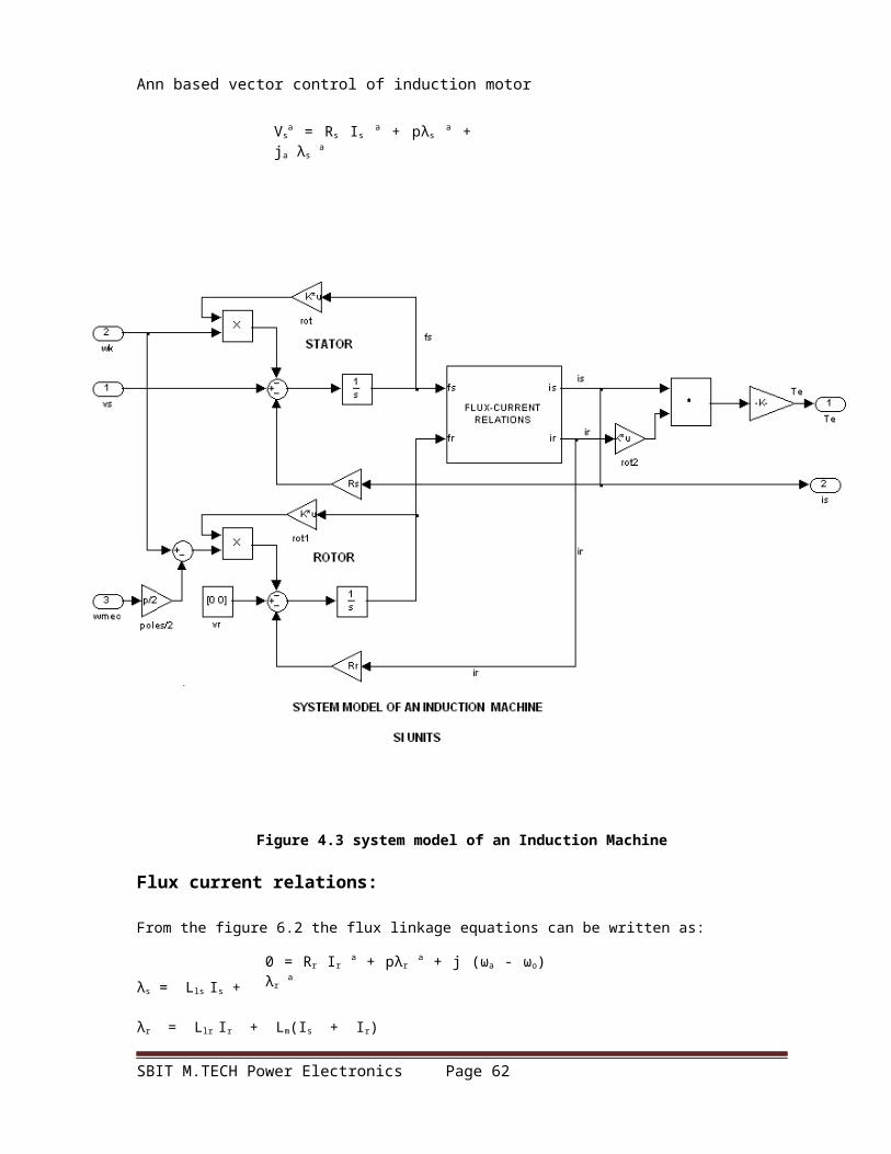
Ann based vector control of induction motor
Fig 6.4 : Speed and time characteristics of an induction motor using a conventional PI
controller
SBIT M.TECH Power Electronics Page 62

Ann based vector control of induction motor
Fig 6.5 :Torque and time characteristics of an induction motor using a conventional PI controller
SBIT M.TECH Power Electronics Page 63

Ann based vector control of induction motor
Fig 6.6 : Speed and time characteristics of an induction motor using a Neural Networks based controller:
SBIT M.TECH Power Electronics Page 64

Ann based vector control of induction motor
Fig 6.6 Speed and time characteristics of an induction motor using a Neural Networks based controller
SBIT M.TECH Power Electronics Page 65

Ann based vector control of induction motor
CHAPTER - 6
CONCLUSION
In this project the dynamic model induction motor is developed in the SIMULINK,
and the vector controller is interfaced with it in the SIMULINK. The PI controller is
designed with appropriate gain values and interfaced to the vector controlled induction
motor. The system is simulated in the MATLAB and the results are observed.
The results of the PI controlled system are not accurate as it shows peak
overshoot. To overcome this Neural Networks based controller is implemented, which
reduces the overshoot and gives more accurate results than PI based controller. So,
Neural Networks controller is an attractive technique when the plant model is complex.
The only drawback of using more neurons in the hidden layer is the increased in number
of weights and therefore the calculations involved in the training algorithm.
The extension of this project is to implementation of Neuro-Fuzzy Controller
(NEFCON) for further better performance. NEFCON combines the merits of fuzzy systems
and neural networks.
SBIT M.TECH Power Electronics Page 66

Ann based vector control of induction motor
BIBILOGRAPHY
1. ARTIFICIAL NEURAL NETWORKS— B.YAGNA NARAYANA
2. AN INTRODUCTION TO NEURAL NETWORKS— J.A.ANDERSON
3. ELECTRICAL MACHINES— P.S.BIMBRA
4. ELECTRICAL MACHINES— S.K.BHATTA CHARYA
5. MACHINE MODELLING – KRAUSE
6. ELECTRICAL DRIVES---- VEDAM SUBRAMANYAM
7. MODERN POWER ELECTRONICS AND AC DRIVES-----BIMAL.K.BOSE
SBIT M.TECH Power Electronics Page 67