Speed Control of DC Motor
24
Speed Control of DC Motor Speed control means intentional change of the drive speed to a value required for performing the specific work process. Speed control is a different concept from speed regulation where there is natural change in speed due change in load on the shaft. Speed control is either done manually by the operator or by means of some automatic control device. One of the important features of dc motor is that its speed can be controlled with relative ease. We know that the expression of speed control dc motor is given as, Therefore speed (N ) of 3 types of dc motor – SERIES, SHUNT AND COMPOUND can be controlled by changing the quantities on RHS of the expression. So speed can be varied by changing (i) terminal voltage of the armature V , (ii) external resistance in armature circuit R and (iii) flux per pole φ . The first two cases involve change that affects armature circuit and the third one involves change in magnetic field. Therefore speed control of dc motor is classified as 1) armature control methods and 2) field control methods. Speed Control of DC Series Motor Speed control of dc series motor can be done either by armature control or by field control.
-
Upload
vijaya-lakshmi -
Category
Documents
-
view
46 -
download
2
description
motor
Transcript of Speed Control of DC Motor
Speed Control of DC Motor
Speed control means intentional change of the drive speed to a value required for performing the specific work process. Speed control is a different concept from speed regulation where there is natural change in speed due change in load on the shaft. Speed control is either done manually by the operator or by means of some automatic control device.
One of the important features of dc motor is that its speed can be controlled with relative ease.
We know that the expression of speed control dc motor is given as,
Therefore speed (N ) of 3 types of dc motor – SERIES, SHUNT AND COMPOUND can be
controlled by changing the quantities on RHS of the expression. So speed can be varied by
changing
(i) terminal voltage of the armature V ,
(ii) external resistance in armature circuit R and
(iii) flux per pole φ .
The first two cases involve change that affects armature circuit and the third one involves change
in magnetic field. Therefore speed control of dc motor is classified as
1) armature control methods and
2) field control methods.
Speed Control of DC Series Motor
Speed control of dc series motor can be done either by armature control or by field control.
Armature Control of DC Series Motor
Speed adjustment of dc series motor by armature control may be done by any one of the methods
that follow,

1. Armature resistance control method: This is the most common method employed. Here the
controlling resistance is connected directly in series with the supply to the motor The power loss
in the control resistance of dc series motor can be neglected because this control method is
utilized for a large portion of time for reducing the speed under light load condition. This method
of speed control is most economical for constant torque. This method of speed control is
employed for dc series motor driving cranes, hoists, trains etc.
2. Shunted armature control: The combination of a rheostat shunting the armature and a rheostat
in series with the armature is involved in this method of speed control. The voltage applied to the
armature is varies by varying series rheostat R 1. The exciting current can be varied by varying
the armature shunting resistance R2. This method of speed control is not economical due to
considerable power losses in speed controlling resistances. Here speed control is obtained over
wide range but below normal speed.
3. Armature terminal voltage control: The speed control of dc series motor can be accomplished by supplying the power to the motor from a separate variable voltage supply. This method involves high cost so it rarely used.
Field control of DC Series Motor
The speed of dc motor can be controlled by this method by any one of the following ways –
1. Field diverter method: This method uses a diverter .Here the field flux can be reduced by shunting
a portion of motor current around the series field. Lesser the diverter resistance less is the field
current, less flux therefore more speed. This method gives speed above normal and the method is
used in electric drives in which speed should rise sharply as soon as load is decreased.
2. Tapped Field control: This is another method of increasing the speed by reducing the flux and it is
done by lowering number of turns of field winding through which current flows. In this method a
number of tapings from field winding are brought outside . This method is employed in electric
traction.
Speed Control of DC Shunt Motor
Speed of dc shunt motor is controlled by the factors stated below

Field control of DC Shunt Motor
By this method speed control is obtained by any one of the following means –
1. Field rheostat control of DC Shunt Motor: In this method , speed variation is accomplished by
means of a variable resistance inserted in series with the shunt field . An increase in controlling
resistances reduces the field current with a reduction in flux and an increase in speed. This
method of speed control is independent of load on the motor. Power wasted in controlling
resistance is very less as field current is a small value. This method of speed control is also used
in DC compound motor.
Limitations of this method of speed control:
A. Creeping speeds cannot be obtained.
B. Top speeds only obtained at reduced torque
C. The speed is maximum at minimum value of flux, which is governed by the demagnetizing
effect of armature reaction on the field.
2. Field voltage control: This method requires a variable voltage supply for the field circuit
which is separated from the main power supply to which the armature is connected. Such a
variable supply can be obtained by an electronic rectifier.
Armature control of DC Shunt Motor
Speed control by this method involves two ways . These are :
1. Armature resistance control : In this method armature circuit is provided with a variable
resistance. Field is directly connected across the supply so flux is not changed due to variation of
series resistance. This is applied for dc shunt motor. This method is used in printing press,
cranes, hoists where speeds lower than rated is used for a short period only.
2. Armature voltage control: This method of speed control needs a variable source of voltage
separated from the source supplying the field current. This method avoids disadvantages of poor
speed regulation and low efficiency of armature-resistance control methods. The basic adjustable
armature voltage control method of speed d control is accomplished by means of an adjustable
voltage generator is called Ward Leonard system.

This method involves using a motor –generator (M-G) set. This method is best suited for steel
rolling mills, paper machines, elevators, mine hoists, etc.
Advantages of this method –
A. Very fine speed control over whole range in both directions
B. Uniform acceleration is obtained
C. Good speed regulation
Disadvantages –
A. Costly arrangement is needed , floor space required is more
B. Low efficiency at light loads
AC Motor Speed Control
AC Induction Motor Speed Control
►So what can we do to control the speed of an AC induction motor?
Change the number of poles (in discrete increments - inefficient & rarely done)�Change the frequency of the AC signal�Change the slip�Change AC Frequency
►Variable speed AC Motor adjustable speed drives are known as inverters,
variable frequency drives (VFD) , or adjustable speed drives (ASD).�►Common ways to vary AC frequency:
Six-step inverter�Pulse-Width-Modulation�Vector Flux�

Six-step Inverter
►AC rectified to DC, then switched to imitate a sine wavealso called a Variable Voltage Inverter or VVI
Pulse-Width-Modulation
►DC voltage (rectified AC) rapidly switched to match "area under curve" also called Pulse-Density-Modulation
Changing Rotor Slip
►Important to match the motor to the load ensure that a change in motor power gives a desired change in load speed
►Load should have a substantial inertial components inertial torque can "carry" the load through brief periods when motor torque cannot
►Best used with motors designed for high slip
Variable Series Resistance
►Additional series resistance reduces voltage across main windings
Variable Voltage Transformer
►More efficient than previous method, no power wasted in the series resistance
Tapped Winding
►Commonly used with 3-speed fan motors (like the one in AC Motor Lab)

STARTER
Necessity of starter
At starting ,the speed of motor is zero so that the back e.m.f. In the armature is zero.
Armature resistance is so low, if it is connected to power supply directly ; huge current will pass thru armature.
The huge current may damage the machine, major heat, very high speed in case of DC series motor.
Ia = V/Ra
Function of starter
Start and stop the motor.
Limit inrush current where necessary.
Permit automatic control when required
Protect motor and other connected equipments from over voltage, no voltage, under voltage, single phasing etc.
Motor Starter Features.
Rated by current (amperes) or power (horsepower)
Remote ON/OFF control
Motor overload protection
Starting and stopping (electrical life)

Plugging and jogging (rapid making and breaking current)
Type of starter
For DC Motor
Two point starter for DC series motor
Three point starter for shunt motor
Four point starter for compound motor
For AC Motor
DOL Starter
Star-Delta
Auto-transformer
Variable Frequency drive

Wiring Diagram of DOL Starte
r:
Motor Starting Characteristics on DOL Starter:
Available starting current: 100%.
Peak starting current: 6 to 8 Full Load Current.
Peak starting torque: 100%
Advantages of DOL Starter:
Most Economical and Cheapest Starter
Simple to establish, operate and maintain
Simple Control Circuitry
Easy to understand and trouble‐shoot.

It provides 100% torque at the time of starting.
Only one set of cable is required from starter to motor.
Motor is connected in delta at motor terminals.
Disadvantages of DOL Starter:
It does not reduce the starting current of the motor.
High Starting Current: Very High Starting Current (Typically 6 to 8 times the FLC of the motor).
Mechanically Harsh: Thermal Stress on the motor, thereby reducing its life.
Voltage Dip: There is a big voltage dip in the electrical installation
High starting Torque: Unnecessary high starting torque, even when not required by the load.
Suitability
DOL is Suitable for:
Small water pumps, compressors, fans and conveyor belts.
Motor rating up to 5.5KW
DOL is not suitable for:
The peak starting current would result in a serious voltage drop on the supply system
Motor rating above 5.5KW
Star delta starter

Most induction motors are started directly on line, but when very large motors are started that way, they cause a disturbance of voltage on the supply lines due to large starting current surges.
To limit the starting current surge, large induction motors are started at reduced voltage and then have full supply voltage reconnected when they run up to near rotated speed.
Star-Delta Connection in transformer
Star-Delta Connection in motor
Star delta power circuit
Star delta control circuit

Motor Starting Characteristics of Star-Delta Starter:
Available starting current: 33% Full Load Current.
Peak starting current: 1.3 to 2.6 Full Load Current.
Peak starting torque: 33% Full Load Torque.
Advantages of Star-Delta starter:
The operation of the star-delta method is simple and rugged
It is relatively cheap compared to other reduced voltage methods.
Good Torque/Current Performance.
It draws 2 times starting current of the full load ampere of the motor connected

Disadvantages of Star-Delta starter:
Low Starting Torque, only 33% starting torque
Break In Supply – Possible Transients
Six Terminal Motor Required (Delta Connected).
It requires 2 set of cables from starter to motor.
The delta of motor is formed in starter and not on motor terminals.
Applications with a load torque higher than 50 % of the motor rated torque will not be able to start using the start-delta starter.
Low Starting Torque: reduction of the line voltage by a factor of 1/√3 (57.7%) to the motor and the current is reduced to 1/3 of the current at full voltage, but the starting torque is also reduced 1/3 to 1/5 of the DOL starting torque .
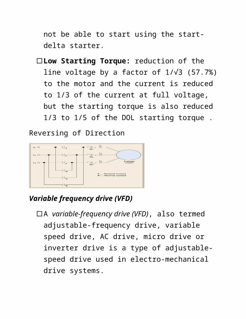
Reversing of Direction
Variable frequency drive (VFD)

A variable-frequency drive (VFD), also termed adjustable-frequency drive, variable speed drive, AC drive, micro drive or inverter drive is a type of adjustable-speed drive used in electro-mechanical drive systems.
It controls AC motor speed and torque by varying motor input frequency and voltage.
Principle of VFD
Variable frequency Drive, principle of the same is by regulating the frequency, we can regulate the speed of drive
Example - n=120f/p
Where,
n - speed
f - frequency
p – nos. of poles
VFD flow diagram
VFD 3-phase power conversion
Application Application
Cane Carrier Drive,
Feeder Table Drive,
Milling Plant Drive,
Raw juice Pumps,
Sulphited Juice Pumps,
Molasses Pumps,
Injection Pumps,
Cooling Tower Pumps and
Centrifugals for a Sugar Curing and Chemical Dosing pump.
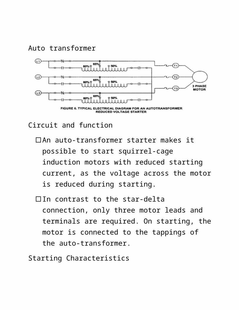
Auto transformer
Circuit and function
An auto-transformer starter makes it possible to start squirrel-cage induction motors with reduced starting current, as the voltage across the motor is reduced during starting.
In contrast to the star-delta connection, only three motor leads and terminals are required. On starting, the motor is connected to the tappings of the auto-transformer.
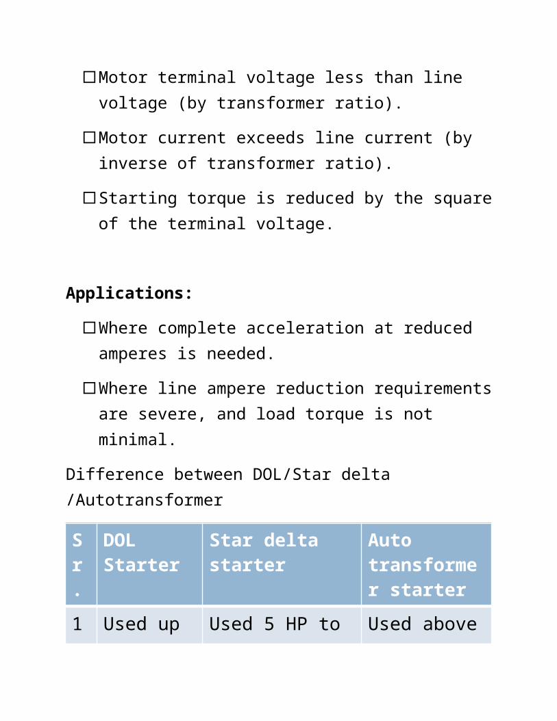
Starting Characteristics
Motor terminal voltage less than line voltage (by transformer ratio).
Motor current exceeds line current (by inverse of transformer ratio).
Starting torque is reduced by the square of the terminal voltage.
Applications:

Where complete acceleration at reduced amperes is needed.
Where line ampere reduction requirements are severe, and load torque is not minimal.
Difference between DOL/Star delta /Autotransformer
Sr.
DOL Starter
Star delta starter
Auto transformer starter
1 Used up to 5 HP
Used 5 HP to 20HP
Used above 20 HP
2 Does not decrease the starting current
Decreases the starting current by 1/3 times
Decreases the starting current as required
3 It is cheap
It is costly It is more costly
4 It connects directly the motor with supply for starting as well as
It connects the motor first in star at the time of starting in delta for running
It connects the motor according to the taping taken out from the auto transformer

for running
KV Series
Super-small Programmable Logic Controllers
General Specifications(R and T in model names indicate relay output and transistor output)
Model KV-10RWKV-10T2W
KV-16RWKV-16T2W
KV-24RWKV-24T2W
KV-40RWKV-40T2W
KV-80RWKV-80TW
Programming language
Ladder diagram and expanded ladder diagram
Number of instructions
Basic: 16, application: 34, arithmetic:26, interrupt: 4
Execution time(basic I/O instructions)
1.0 µs min., 1.92 µs average 1.4 µs min., 3.12 µs average
Avg. number of steps 500 steps/program 3000 steps/program
Input (Maximum extendable number of inputs)
6 inputs(70 max.)
10 inputs(74 max.)
16 inputs(80 max.)
24 inputs(72 max.)
48 inputs(80 max.)
Output (Maximum extendable number of inputs)
4 outputs(68 max.)
6 outpus(70 max.)
8 outputs(72 max.)
16 outputs(80 max.)
32 outputs(80 max.)
Maximum extendable number of I/Os
74 80 88 88 128
Internal utility relays(with latching function)
160 800
Special utility relays 160 160
Data memory(16 bits)
1,000 words 2,000 words
Temporary memory (16 bits)
32 words 32 words
Timer/counter
A total of 64 timers, up, and up-down counters are
provided: 0.1-s timer (0 to 6553.5 s)0.01-s timer (0 to 655.35
s)1-ms timer (0 to 65.535 s)1 analog timer (0 to 24.9
s, 0 to 2.49 s, or 0 to 0.249 s)
A total of 120 timers, up, and up-down counters are provided:
0.1-s timer (0 to 6553.5 s)0.01-s timer (0 to 655.35 s)1-ms timer (0 to 65.535 s)
2 analog timers (two of 0 to 24.9 s, 0 to 2.49 s, or 0 to 0.249 s)
High-speed counter 2 auto-reset up-counters (max. input response frequency: 10 kHz)
High-speed counter comparator
4 4
Direct clock pulse
2 channels, 2 kHz max.(output from 0500), 1.5 kHz max. (output from
0501)
2 channels, 2 kHz max.(output from 0500), 1.5 kHz max. (output from
0501)
2 channels, 20 kHz max. (output from
0500), 1.5 kHz max.
(output from 0501)
Memory backup
Program memory: EEPROM, programs retained for 10 years min., rewritable 50,000 times min.
Data memory: data retained for 2 months min. by capacitors (at 25°C)
Supply voltage 24 VDC +10% to -20%
Maximum current consumption
KV-10RW: 75 mA
KV-10T2W: 65 mA
KV-16RW: 105 mA
KV-16T2W: 70 mA
KV-24RW: 130 mA
KV-24T2W: 75 mA
KV-40RW: 220 mA
KV-40T2W: 115 mA
KV-80RW: 400 mA
KV-80TW: 300 mA
Ambient temperature 0 to 50°C
Withstand voltage 1500 VAC applied between power terminal and I/O terminal, and between terminals and housing (1 min.)
Weight
KV-10RW: approx. 130
gKV-10T2W: approx. 120
g
KV-16RW: approx. 200
gKV-16T2W: approx. 180
g
KV-24RW: approx. 250
gKV-24T2W: approx. 220
g
KV-40RW: approx. 340
gKV-40T2W: approx. 270
g
KV-80RW: approx. 600
gKV-80TW:
approx. 500 g
input/Output Specifications
Type Basic unit
Model KV-10RW
KV-16RW
KV-24RW
KV-40RW
KV-80RW
KV-10T2W
KV-16T2W
KV-24T2W
KV-40T2W
KV-80T2W
No. of inputs
6 10 16 24 48 6 10 16 24 48
No. of outputs
4 6 8 16 32 4 6 8 16 32
Type of output
Relay Relay Relay Relay Relay BJT MOS-FET
MOS-FET
MOS-FET
BJT
Type Expansion unit
Model KV-8ERW
KV-8ET2W
KV-8EXW
KV-8EYRW
KV-8EYT2W
KV-16EXW
KV-16EYRW
KV-16EYTW
No. of inputs 4 4 8 - - 16 - -
No. of outputs 4 4 - 8 8 - 16 16
Type of output
Relay BJT - Relay BJT - Relay BJT
Power Supply Unit SpecificationsModel KV-U6W
Operation system Switching type
Power supply voltage 100 to 240 VAC (50/60 Hz) ±10%
Output voltage 24 VDC ±10% (Ripple: 240 m Vp-p max.)
Output current 0.8 A
Weight (brackets not included) Approx. 210 g
Analog I/O Specifications (Input: KV-AD4, Output: KV-DA4)Type Voltage Current
Analog I/O range -10 to +10 V 4 to 20 mA
Input impedance 1 M ohm 300 ohm
Output impedance
0.5 ohm min. -
Number of I/O 4 channels of inputs or outputs 4 channels of inputs or outputs
Resolution 5 mV (1/4000) 4 µA (1/4000)