Specular reflections and the estimation of shape from
6
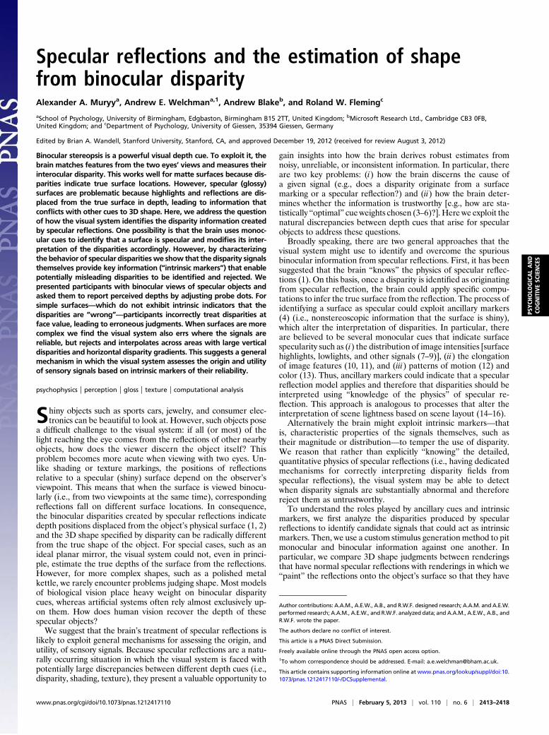
Specular reflections and the estimation of shape from binocular disparity Alexander A. Muryy a , Andrew E. Welchman a,1 , Andrew Blake b , and Roland W. Fleming c a School of Psychology, University of Birmingham, Edgbaston, Birmingham B15 2TT, United Kingdom; b Microsoft Research Ltd., Cambridge CB3 0FB, United Kingdom; and c Department of Psychology, University of Giessen, 35394 Giessen, Germany Edited by Brian A. Wandell, Stanford University, Stanford, CA, and approved December 19, 2012 (received for review August 3, 2012) Binocular stereopsis is a powerful visual depth cue. To exploit it, the brain matches features from the two eyes’ views and measures their interocular disparity. This works well for matte surfaces because dis- parities indicate true surface locations. However, specular (glossy) surfaces are problematic because highlights and reflections are dis- placed from the true surface in depth, leading to information that conflicts with other cues to 3D shape. Here, we address the question of how the visual system identifies the disparity information created by specular reflections. One possibility is that the brain uses monoc- ular cues to identify that a surface is specular and modifies its inter- pretation of the disparities accordingly. However, by characterizing the behavior of specular disparities we show that the disparity signals themselves provide key information (“intrinsic markers”) that enable potentially misleading disparities to be identified and rejected. We presented participants with binocular views of specular objects and asked them to report perceived depths by adjusting probe dots. For simple surfaces—which do not exhibit intrinsic indicators that the disparities are “wrong”—participants incorrectly treat disparities at face value, leading to erroneous judgments. When surfaces are more complex we find the visual system also errs where the signals are reliable, but rejects and interpolates across areas with large vertical disparities and horizontal disparity gradients. This suggests a general mechanism in which the visual system assesses the origin and utility of sensory signals based on intrinsic markers of their reliability. psychophysics | perception | gloss | texture | computational analysis S hiny objects such as sports cars, jewelry, and consumer elec- tronics can be beautiful to look at. However, such objects pose a difficult challenge to the visual system: if all (or most) of the light reaching the eye comes from the reflections of other nearby objects, how does the viewer discern the object itself? This problem becomes more acute when viewing with two eyes. Un- like shading or texture markings, the positions of reflections relative to a specular (shiny) surface depend on the observer’s viewpoint. This means that when the surface is viewed binocu- larly (i.e., from two viewpoints at the same time), corresponding reflections fall on different surface locations. In consequence, the binocular disparities created by specular reflections indicate depth positions displaced from the object’s physical surface (1, 2) and the 3D shape specified by disparity can be radically different from the true shape of the object. For special cases, such as an ideal planar mirror, the visual system could not, even in princi- ple, estimate the true depths of the surface from the reflections. However, for more complex shapes, such as a polished metal kettle, we rarely encounter problems judging shape. Most models of biological vision place heavy weight on binocular disparity cues, whereas artificial systems often rely almost exclusively up- on them. How does human vision recover the depth of these specular objects? We suggest that the brain’s treatment of specular reflections is likely to exploit general mechanisms for assessing the origin, and utility, of sensory signals. Because specular reflections are a natu- rally occurring situation in which the visual system is faced with potentially large discrepancies between different depth cues (i.e., disparity, shading, texture), they present a valuable opportunity to gain insights into how the brain derives robust estimates from noisy, unreliable, or inconsistent information. In particular, there are two key problems: (i ) how the brain discerns the cause of a given signal (e.g., does a disparity originate from a surface marking or a specular reflection?) and (ii ) how the brain deter- mines whether the information is trustworthy [e.g., how are sta- tistically “optimal” cue weights chosen (3–6)?]. Here we exploit the natural discrepancies between depth cues that arise for specular objects to address these questions. Broadly speaking, there are two general approaches that the visual system might use to identify and overcome the spurious binocular information from specular reflections. First, it has been suggested that the brain “knows” the physics of specular reflec- tions (1). On this basis, once a disparity is identified as originating from specular reflection, the brain could apply specific compu- tations to infer the true surface from the reflection. The process of identifying a surface as specular could exploit ancillary markers (4) (i.e., nonstereoscopic information that the surface is shiny), which alter the interpretation of disparities. In particular, there are believed to be several monocular cues that indicate surface specularity such as (i ) the distribution of image intensities [surface highlights, lowlights, and other signals (7–9)], (ii ) the elongation of image features (10, 11), and (iii ) patterns of motion (12) and color (13). Thus, ancillary markers could indicate that a specular reflection model applies and therefore that disparities should be interpreted using “knowledge of the physics” of specular re- flection. This approach is analogous to processes that alter the interpretation of scene lightness based on scene layout (14–16). Alternatively the brain might exploit intrinsic markers—that is, characteristic properties of the signals themselves, such as their magnitude or distribution—to temper the use of disparity. We reason that rather than explicitly “knowing” the detailed, quantitative physics of specular reflections (i.e., having dedicated mechanisms for correctly interpreting disparity fields from specular reflections), the visual system may be able to detect when disparity signals are substantially abnormal and therefore reject them as untrustworthy. To understand the roles played by ancillary cues and intrinsic markers, we first analyze the disparities produced by specular reflections to identify candidate signals that could act as intrinsic markers. Then, we use a custom stimulus generation method to pit monocular and binocular information against one another. In particular, we compare 3D shape judgments between renderings that have normal specular reflections with renderings in which we “paint” the reflections onto the object’s surface so that they have Author contributions: A.A.M., A.E.W., A.B., and R.W.F. designed research; A.A.M. and A.E.W. performed research; A.A.M., A.E.W., and R.W.F. analyzed data; and A.A.M., A.E.W., A.B., and R.W.F. wrote the paper. The authors declare no conflict of interest. This article is a PNAS Direct Submission. Freely available online through the PNAS open access option. 1 To whom correspondence should be addressed. E-mail: [email protected]. This article contains supporting information online at www.pnas.org/lookup/suppl/doi:10. 1073/pnas.1212417110/-/DCSupplemental. www.pnas.org/cgi/doi/10.1073/pnas.1212417110 PNAS | February 5, 2013 | vol. 110 | no. 6 | 2413–2418 PSYCHOLOGICAL AND COGNITIVE SCIENCES
Transcript of Specular reflections and the estimation of shape from
Specular reflections and the estimation of shapefrom binocular disparityAlexander A. Muryya, Andrew E. Welchmana,1, Andrew Blakeb, and Roland W. Flemingc
aSchool of Psychology, University of Birmingham, Edgbaston, Birmingham B15 2TT, United Kingdom; bMicrosoft Research Ltd., Cambridge CB3 0FB,United Kingdom; and cDepartment of Psychology, University of Giessen, 35394 Giessen, Germany
Edited by Brian A. Wandell, Stanford University, Stanford, CA, and approved December 19, 2012 (received for review August 3, 2012)
Binocular stereopsis is a powerful visual depth cue. To exploit it, thebrain matches features from the two eyes’ views and measures theirinterocular disparity. This works well for matte surfaces because dis-parities indicate true surface locations. However, specular (glossy)surfaces are problematic because highlights and reflections are dis-placed from the true surface in depth, leading to information thatconflicts with other cues to 3D shape. Here, we address the questionof how the visual system identifies the disparity information createdby specular reflections. One possibility is that the brain uses monoc-ular cues to identify that a surface is specular and modifies its inter-pretation of the disparities accordingly. However, by characterizingthe behavior of specular disparitieswe show that the disparity signalsthemselves provide key information (“intrinsic markers”) that enablepotentially misleading disparities to be identified and rejected. Wepresented participants with binocular views of specular objects andasked them to report perceived depths by adjusting probe dots. Forsimple surfaces—which do not exhibit intrinsic indicators that thedisparities are “wrong”—participants incorrectly treat disparities atface value, leading to erroneous judgments. When surfaces are morecomplex we find the visual system also errs where the signals arereliable, but rejects and interpolates across areas with large verticaldisparities and horizontal disparity gradients. This suggests a generalmechanism in which the visual system assesses the origin and utilityof sensory signals based on intrinsic markers of their reliability.
psychophysics | perception | gloss | texture | computational analysis
Shiny objects such as sports cars, jewelry, and consumer elec-tronics can be beautiful to look at. However, such objects pose
a difficult challenge to the visual system: if all (or most) of thelight reaching the eye comes from the reflections of other nearbyobjects, how does the viewer discern the object itself? Thisproblem becomes more acute when viewing with two eyes. Un-like shading or texture markings, the positions of reflectionsrelative to a specular (shiny) surface depend on the observer’sviewpoint. This means that when the surface is viewed binocu-larly (i.e., from two viewpoints at the same time), correspondingreflections fall on different surface locations. In consequence,the binocular disparities created by specular reflections indicatedepth positions displaced from the object’s physical surface (1, 2)and the 3D shape specified by disparity can be radically differentfrom the true shape of the object. For special cases, such as anideal planar mirror, the visual system could not, even in princi-ple, estimate the true depths of the surface from the reflections.However, for more complex shapes, such as a polished metalkettle, we rarely encounter problems judging shape. Most modelsof biological vision place heavy weight on binocular disparitycues, whereas artificial systems often rely almost exclusively up-on them. How does human vision recover the depth of thesespecular objects?We suggest that the brain’s treatment of specular reflections is
likely to exploit general mechanisms for assessing the origin, andutility, of sensory signals. Because specular reflections are a natu-rally occurring situation in which the visual system is faced withpotentially large discrepancies between different depth cues (i.e.,disparity, shading, texture), they present a valuable opportunity to
gain insights into how the brain derives robust estimates fromnoisy, unreliable, or inconsistent information. In particular, thereare two key problems: (i) how the brain discerns the cause ofa given signal (e.g., does a disparity originate from a surfacemarking or a specular reflection?) and (ii) how the brain deter-mines whether the information is trustworthy [e.g., how are sta-tistically “optimal” cueweights chosen (3–6)?].Here we exploit thenatural discrepancies between depth cues that arise for specularobjects to address these questions.Broadly speaking, there are two general approaches that the
visual system might use to identify and overcome the spuriousbinocular information from specular reflections. First, it has beensuggested that the brain “knows” the physics of specular reflec-tions (1). On this basis, once a disparity is identified as originatingfrom specular reflection, the brain could apply specific compu-tations to infer the true surface from the reflection. The process ofidentifying a surface as specular could exploit ancillary markers(4) (i.e., nonstereoscopic information that the surface is shiny),which alter the interpretation of disparities. In particular, thereare believed to be several monocular cues that indicate surfacespecularity such as (i) the distribution of image intensities [surfacehighlights, lowlights, and other signals (7–9)], (ii) the elongationof image features (10, 11), and (iii) patterns of motion (12) andcolor (13). Thus, ancillary markers could indicate that a specularreflection model applies and therefore that disparities should beinterpreted using “knowledge of the physics” of specular re-flection. This approach is analogous to processes that alter theinterpretation of scene lightness based on scene layout (14–16).Alternatively the brain might exploit intrinsic markers—that
is, characteristic properties of the signals themselves, such astheir magnitude or distribution—to temper the use of disparity.We reason that rather than explicitly “knowing” the detailed,quantitative physics of specular reflections (i.e., having dedicatedmechanisms for correctly interpreting disparity fields fromspecular reflections), the visual system may be able to detectwhen disparity signals are substantially abnormal and thereforereject them as untrustworthy.To understand the roles played by ancillary cues and intrinsic
markers, we first analyze the disparities produced by specularreflections to identify candidate signals that could act as intrinsicmarkers. Then, we use a custom stimulus generation method to pitmonocular and binocular information against one another. Inparticular, we compare 3D shape judgments between renderingsthat have normal specular reflections with renderings in which we“paint” the reflections onto the object’s surface so that they have
Author contributions: A.A.M., A.E.W., A.B., and R.W.F. designed research; A.A.M. and A.E.W.performed research; A.A.M., A.E.W., and R.W.F. analyzed data; and A.A.M., A.E.W., A.B., andR.W.F. wrote the paper.
The authors declare no conflict of interest.
This article is a PNAS Direct Submission.
Freely available online through the PNAS open access option.1To whom correspondence should be addressed. E-mail: [email protected].
This article contains supporting information online at www.pnas.org/lookup/suppl/doi:10.1073/pnas.1212417110/-/DCSupplemental.
www.pnas.org/cgi/doi/10.1073/pnas.1212417110 PNAS | February 5, 2013 | vol. 110 | no. 6 | 2413–2418
PSYC
HOLO
GICALAND
COGNITIVESC
IENCE
S
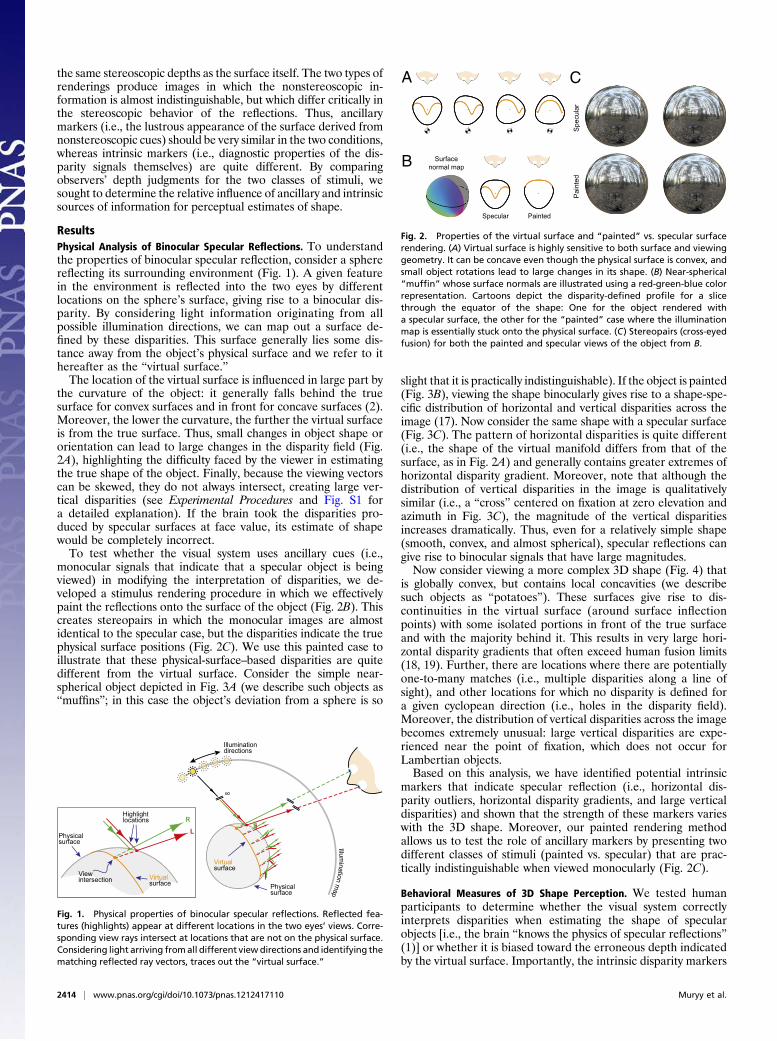
the same stereoscopic depths as the surface itself. The two types ofrenderings produce images in which the nonstereoscopic in-formation is almost indistinguishable, but which differ critically inthe stereoscopic behavior of the reflections. Thus, ancillarymarkers (i.e., the lustrous appearance of the surface derived fromnonstereoscopic cues) should be very similar in the two conditions,whereas intrinsic markers (i.e., diagnostic properties of the dis-parity signals themselves) are quite different. By comparingobservers’ depth judgments for the two classes of stimuli, wesought to determine the relative influence of ancillary and intrinsicsources of information for perceptual estimates of shape.
ResultsPhysical Analysis of Binocular Specular Reflections. To understandthe properties of binocular specular reflection, consider a spherereflecting its surrounding environment (Fig. 1). A given featurein the environment is reflected into the two eyes by differentlocations on the sphere’s surface, giving rise to a binocular dis-parity. By considering light information originating from allpossible illumination directions, we can map out a surface de-fined by these disparities. This surface generally lies some dis-tance away from the object’s physical surface and we refer to ithereafter as the “virtual surface.”The location of the virtual surface is influenced in large part by
the curvature of the object: it generally falls behind the truesurface for convex surfaces and in front for concave surfaces (2).Moreover, the lower the curvature, the further the virtual surfaceis from the true surface. Thus, small changes in object shape ororientation can lead to large changes in the disparity field (Fig.2A), highlighting the difficulty faced by the viewer in estimatingthe true shape of the object. Finally, because the viewing vectorscan be skewed, they do not always intersect, creating large ver-tical disparities (see Experimental Procedures and Fig. S1 fora detailed explanation). If the brain took the disparities pro-duced by specular surfaces at face value, its estimate of shapewould be completely incorrect.To test whether the visual system uses ancillary cues (i.e.,
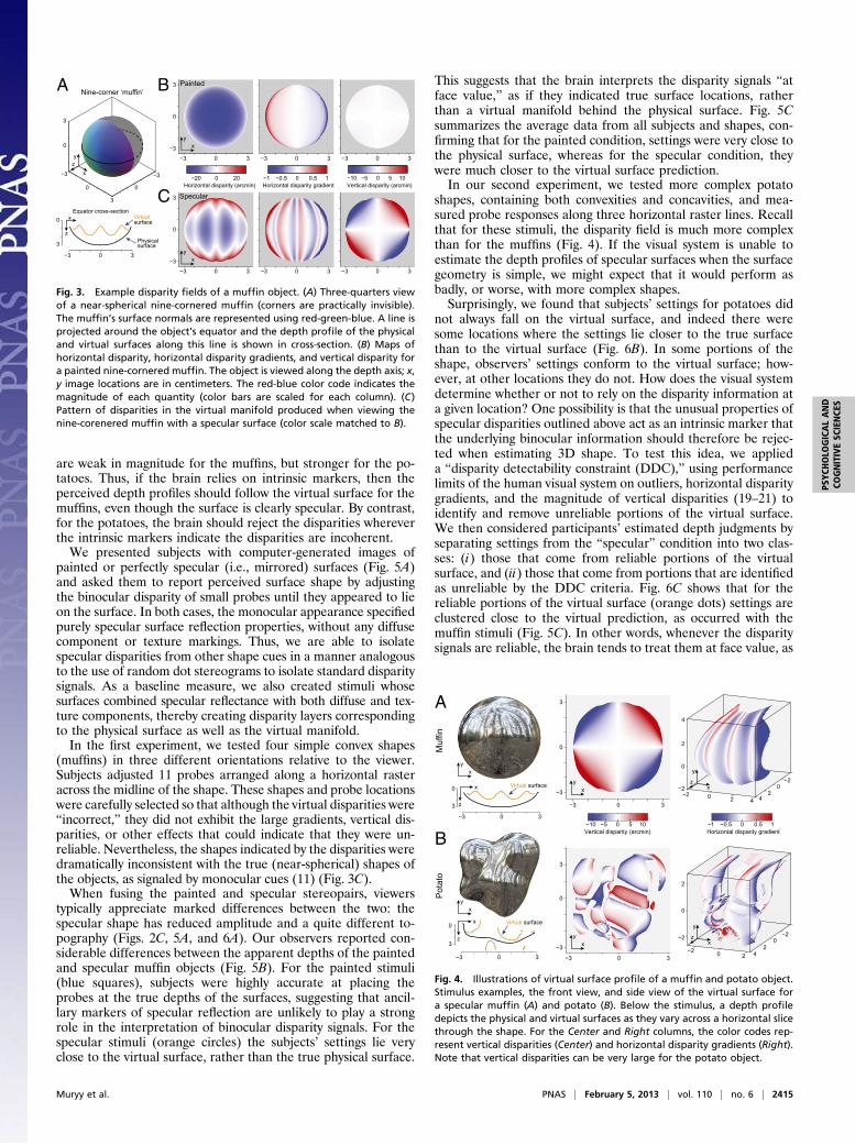
monocular signals that indicate that a specular object is beingviewed) in modifying the interpretation of disparities, we de-veloped a stimulus rendering procedure in which we effectivelypaint the reflections onto the surface of the object (Fig. 2B). Thiscreates stereopairs in which the monocular images are almostidentical to the specular case, but the disparities indicate the truephysical surface positions (Fig. 2C). We use this painted case toillustrate that these physical-surface–based disparities are quitedifferent from the virtual surface. Consider the simple near-spherical object depicted in Fig. 3A (we describe such objects as“muffins”; in this case the object’s deviation from a sphere is so
slight that it is practically indistinguishable). If the object is painted(Fig. 3B), viewing the shape binocularly gives rise to a shape-spe-cific distribution of horizontal and vertical disparities across theimage (17). Now consider the same shape with a specular surface(Fig. 3C). The pattern of horizontal disparities is quite different(i.e., the shape of the virtual manifold differs from that of thesurface, as in Fig. 2A) and generally contains greater extremes ofhorizontal disparity gradient. Moreover, note that although thedistribution of vertical disparities in the image is qualitativelysimilar (i.e., a “cross” centered on fixation at zero elevation andazimuth in Fig. 3C), the magnitude of the vertical disparitiesincreases dramatically. Thus, even for a relatively simple shape(smooth, convex, and almost spherical), specular reflections cangive rise to binocular signals that have large magnitudes.Now consider viewing a more complex 3D shape (Fig. 4) that
is globally convex, but contains local concavities (we describesuch objects as “potatoes”). These surfaces give rise to dis-continuities in the virtual surface (around surface inflectionpoints) with some isolated portions in front of the true surfaceand with the majority behind it. This results in very large hori-zontal disparity gradients that often exceed human fusion limits(18, 19). Further, there are locations where there are potentiallyone-to-many matches (i.e., multiple disparities along a line ofsight), and other locations for which no disparity is defined fora given cyclopean direction (i.e., holes in the disparity field).Moreover, the distribution of vertical disparities across the imagebecomes extremely unusual: large vertical disparities are expe-rienced near the point of fixation, which does not occur forLambertian objects.Based on this analysis, we have identified potential intrinsic
markers that indicate specular reflection (i.e., horizontal dis-parity outliers, horizontal disparity gradients, and large verticaldisparities) and shown that the strength of these markers varieswith the 3D shape. Moreover, our painted rendering methodallows us to test the role of ancillary markers by presenting twodifferent classes of stimuli (painted vs. specular) that are prac-tically indistinguishable when viewed monocularly (Fig. 2C).
Behavioral Measures of 3D Shape Perception. We tested humanparticipants to determine whether the visual system correctlyinterprets disparities when estimating the shape of specularobjects [i.e., the brain “knows the physics of specular reflections”(1)] or whether it is biased toward the erroneous depth indicatedby the virtual surface. Importantly, the intrinsic disparity markers
Illumination
mapPhysical
surface
Virtual surface
∞
Illumination directions
Physicalsurface
R
L
Highlight locations
View intersection Virtual
surface
Fig. 1. Physical properties of binocular specular reflections. Reflected fea-tures (highlights) appear at different locations in the two eyes’ views. Corre-sponding view rays intersect at locations that are not on the physical surface.Considering light arriving fromall different viewdirections and identifying thematching reflected ray vectors, traces out the “virtual surface.”
Surface normal map
Specular Painted
CA
B
Pai
nted
Spe
cula
r
Fig. 2. Properties of the virtual surface and “painted” vs. specular surfacerendering. (A) Virtual surface is highly sensitive to both surface and viewinggeometry. It can be concave even though the physical surface is convex, andsmall object rotations lead to large changes in its shape. (B) Near-spherical“muffin” whose surface normals are illustrated using a red-green-blue colorrepresentation. Cartoons depict the disparity-defined profile for a slicethrough the equator of the shape: One for the object rendered witha specular surface, the other for the “painted” case where the illuminationmap is essentially stuck onto the physical surface. (C) Stereopairs (cross-eyedfusion) for both the painted and specular views of the object from B.
2414 | www.pnas.org/cgi/doi/10.1073/pnas.1212417110 Muryy et al.
are weak in magnitude for the muffins, but stronger for the po-tatoes. Thus, if the brain relies on intrinsic markers, then theperceived depth profiles should follow the virtual surface for themuffins, even though the surface is clearly specular. By contrast,for the potatoes, the brain should reject the disparities whereverthe intrinsic markers indicate the disparities are incoherent.We presented subjects with computer-generated images of
painted or perfectly specular (i.e., mirrored) surfaces (Fig. 5A)and asked them to report perceived surface shape by adjustingthe binocular disparity of small probes until they appeared to lieon the surface. In both cases, the monocular appearance specifiedpurely specular surface reflection properties, without any diffusecomponent or texture markings. Thus, we are able to isolatespecular disparities from other shape cues in a manner analogousto the use of random dot stereograms to isolate standard disparitysignals. As a baseline measure, we also created stimuli whosesurfaces combined specular reflectance with both diffuse and tex-ture components, thereby creating disparity layers correspondingto the physical surface as well as the virtual manifold.In the first experiment, we tested four simple convex shapes
(muffins) in three different orientations relative to the viewer.Subjects adjusted 11 probes arranged along a horizontal rasteracross the midline of the shape. These shapes and probe locationswere carefully selected so that although the virtual disparities were“incorrect,” they did not exhibit the large gradients, vertical dis-parities, or other effects that could indicate that they were un-reliable. Nevertheless, the shapes indicated by the disparities weredramatically inconsistent with the true (near-spherical) shapes ofthe objects, as signaled by monocular cues (11) (Fig. 3C).When fusing the painted and specular stereopairs, viewers
typically appreciate marked differences between the two: thespecular shape has reduced amplitude and a quite different to-pography (Figs. 2C, 5A, and 6A). Our observers reported con-siderable differences between the apparent depths of the paintedand specular muffin objects (Fig. 5B). For the painted stimuli(blue squares), subjects were highly accurate at placing theprobes at the true depths of the surfaces, suggesting that ancil-lary markers of specular reflection are unlikely to play a strongrole in the interpretation of binocular disparity signals. For thespecular stimuli (orange circles) the subjects’ settings lie veryclose to the virtual surface, rather than the true physical surface.
This suggests that the brain interprets the disparity signals “atface value,” as if they indicated true surface locations, ratherthan a virtual manifold behind the physical surface. Fig. 5Csummarizes the average data from all subjects and shapes, con-firming that for the painted condition, settings were very close tothe physical surface, whereas for the specular condition, theywere much closer to the virtual surface prediction.In our second experiment, we tested more complex potato
shapes, containing both convexities and concavities, and mea-sured probe responses along three horizontal raster lines. Recallthat for these stimuli, the disparity field is much more complexthan for the muffins (Fig. 4). If the visual system is unable toestimate the depth profiles of specular surfaces when the surfacegeometry is simple, we might expect that it would perform asbadly, or worse, with more complex shapes.Surprisingly, we found that subjects’ settings for potatoes did
not always fall on the virtual surface, and indeed there weresome locations where the settings lie closer to the true surfacethan to the virtual surface (Fig. 6B). In some portions of theshape, observers’ settings conform to the virtual surface; how-ever, at other locations they do not. How does the visual systemdetermine whether or not to rely on the disparity information ata given location? One possibility is that the unusual properties ofspecular disparities outlined above act as an intrinsic marker thatthe underlying binocular information should therefore be rejec-ted when estimating 3D shape. To test this idea, we applieda “disparity detectability constraint (DDC),” using performancelimits of the human visual system on outliers, horizontal disparitygradients, and the magnitude of vertical disparities (19–21) toidentify and remove unreliable portions of the virtual surface.We then considered participants’ estimated depth judgments byseparating settings from the “specular” condition into two clas-ses: (i) those that come from reliable portions of the virtualsurface, and (ii) those that come from portions that are identifiedas unreliable by the DDC criteria. Fig. 6C shows that for thereliable portions of the virtual surface (orange dots) settings areclustered close to the virtual prediction, as occurred with themuffin stimuli (Fig. 5C). In other words, whenever the disparitysignals are reliable, the brain tends to treat them at face value, as
PaintedNine-corner ‘muffin’
Equator cross-section
Specular
A B
C
−3
0
3
−3
−3
0
0
3
3 −3 0 3 −3 0 3
−3 0 3 −3 0 3 −3 0 3
−20 0Horizontal disparity (arcmin) Horizontal disparity gradient Vertical disparity (arcmin)
20 −10 −5 0 5 10−1 −0.5 0 0.5 1
xy
xy
0
0
0
−3 −3
3
3
xzy
x
z
−3 0 3
0
3 Physicalsurface
Virtual surface
Fig. 3. Example disparity fields of a muffin object. (A) Three-quarters viewof a near-spherical nine-cornered muffin (corners are practically invisible).The muffin’s surface normals are represented using red-green-blue. A line isprojected around the object’s equator and the depth profile of the physicaland virtual surfaces along this line is shown in cross-section. (B) Maps ofhorizontal disparity, horizontal disparity gradients, and vertical disparity fora painted nine-cornered muffin. The object is viewed along the depth axis; x,y image locations are in centimeters. The red-blue color code indicates themagnitude of each quantity (color bars are scaled for each column). (C)Pattern of disparities in the virtual manifold produced when viewing thenine-corenered muffin with a specular surface (color scale matched to B).
−10 −5 0 5 10Vertical disparity (arcmin) Horizontal disparity gradient
−1 −0.5 0 0.5 1
Muf
finP
otat
o
−3
0
3
−3
−2−2
−2
00
0
0
3
−3
0
3
−3 0 3
2
2
24
4
4
−2
−2 −2
0
0
0
2
2
24
xy
xy
xy
x
z
x
z
xy
xz
y
xz
y
A
B
0
3
0
3
−3 0 3
−3 0 3
Virtual surface
Virtual surface
Fig. 4. Illustrations of virtual surface profile of a muffin and potato object.Stimulus examples, the front view, and side view of the virtual surface fora specular muffin (A) and potato (B). Below the stimulus, a depth profiledepicts the physical and virtual surfaces as they vary across a horizontal slicethrough the shape. For the Center and Right columns, the color codes rep-resent vertical disparities (Center) and horizontal disparity gradients (Right).Note that vertical disparities can be very large for the potato object.
Muryy et al. PNAS | February 5, 2013 | vol. 110 | no. 6 | 2415
PSYC
HOLO
GICALAND
COGNITIVESC
IENCE
S

if they indicated the actual position of the surface (which, ofcourse they do not). By contrast, where the disparity signal isatypical (Fig. 6C, gray circles), the settings are broadly distrib-uted and are in many cases closer to the physical surface than the“good” virtual surface disparities.What can account for this perhaps counterintuitive result that
settings are closer to the physical surface when specular dis-parities are atypically large or incoherent? One possibility is thatthe visual system could interpolate across the gaps caused bythese signals, basing its estimates on the more reliable in-formation flanking the unreliable regions and shape informationfrom monocular cues. To test this idea, we filtered out unreliabledisparities and interpolated across the resulting gaps in the vir-tual surface using Bezier curve fits as a simple way of imposinga smoothness constraint (22) on the interpolated surface. Theseprediction curves are qualitatively quite similar to the subjects’settings (Fig. 6B, black dashed line), although note these fits arenot intended as a quantitative or biological model of spatial in-terpolation—other interpolation methods may fit subjects’ set-tings more closely. The important idea is that the brain appearsto use some kind of spatial interpolation to deal with missing,inconsistent, or otherwise untrustworthy disparity signals. Sucha strategy would be applicable not only to specular surfaces, butto other “bad” disparity signals as well, such as in refractivemedia (e.g., a heat haze), or when retinal or eye-movement noiseleads to spurious vertical disparity signals, or where contrast islocally too low for disparity to be measured reliably.Whereas many objects encountered in the natural world have
a specular component, purely specular surfaces are relativelyrare—most materials have some combination of specular anddiffuse reflection. In the main experiments, we used purelyspecular surfaces to isolate the information provided by speculardisparities. However, it is interesting to ask how well the brainestimates shape when additional cues are present. We thereforeobtained settings for objects that had partially specular surfaces(i.e., combinations of shading, texture, and specular reflections).These objects provided information about the physical location
of the surface from the binocular disparities associated withsurface texture and shading, as well as information about thevirtual surface overlaid in a physically realistic manner. Un-surprisingly, we found that when a textured surface componentwas visible, observers’ settings lay on the physical surface of theobject (Fig. S2). This suggests that when segmenting the twopotential surface locations, observers select the one that is mostcoherent as the one likely to represent the true surface location.As the relative strength of the surface markings change (e.g., highspatial frequency texture marks become visible relative to lowspatial frequency shading signals), the observer’s impression ofthe surface shape is likely to change.
DiscussionPrevious work has suggested that specular highlights can aid 3Dshape perception (23, 24), especially when combined with othercues (25, 26). However, the presence of a specular highlight doesnot always influence shape judgments (27) and these signals maysometimes be ignored (28). Here, by isolating the specular dis-parity cue, we have identified the specific image quantities thatthe brain could use to reject potentially misleading disparities.It is important to clarify that the extreme values of vertical
disparities and horizontal disparity gradients that are rejected bythe disparity detectability constraint are unfusible and thereforeprobably not encoded at all by the visual system. These portionsalso tend to be flanked by regions that are fusible but still containunusual values. Our computational analysis shows that for com-plex shapes (potatoes), fusible areas appear to be isolatedregions surrounded by unfusible areas. These fusible “islands”correspond to regions of local convexity and concavity, which areisolated from each other by inflection contours where the virtualsurface depths go to infinity. At the borders of these regions thevertical disparities and horizontal disparity gradients reach theirmaximum, beyond which disparities become unavailable. Recentstudies show that the visual system is sensitive to rapid changesof sign in the vertical disparities (29). It is possible that a similarmechanism could help the visual system to identify regions of
CBA
Distance from virtual (cm)
Dis
tanc
e fro
m p
hysi
cal (
cm)
1
1
2
3
00
2 3
PaintedSpecular
Obtuse Oblique Acute1cm1cm
Specular
PaintedFig. 5. Example stimuli and results for muffin objects.(A) Stereopairs for cross-fusing. When viewed mon-ocularly, painted and specular stereopairs are almostindistinguishable. When fused, the painted stereopairappears more matte and more spherical. (B) Data fromthe probe adjustment task. Each row is a single shapeviewed at three orientations relative to the viewer.Black line, physical surface; orange line, virtual sur-face. Settings are shown for painted (blue squares)and specular (orange circles) conditions. Error barsshow SEM across observers. (C ) Scatterplot of settingsin terms of distance from the physical (y axis) andvirtual (x axis) surfaces. Each datum represents the mean setting (across repetitions) of an individual observer for a particular location on one ofthe shapes.
CB Top Middle Bottom
Distance from virtual (cm)
Dis
tanc
e fro
m p
hysi
cal (
cm)
1cm1cm
1
1
2
3
00
2 3
‘Good’ Specular
‘Bad’ SpecularOutliers
Painted
A
Specular
PaintedFig. 6. Example stimuli and results for potato objects. (A)Stereopairs for cross-fusing. (B) Data from the probe ad-justment task. Each row is a single shape; columns showthree rasters through the object (locations illustrated ongray-scale depictions next to the axes). Black line, physicalsurface; orange line, virtual surface. Settings are shownfor painted (blue squares) and specular (orange circles)conditions. Error bars show SEM across subjects. (C) Rel-ative proximity of settings to the physical and virtualsurfaces. Data from the specular surfaces were separatedinto three groups: “good” vs. “bad” specular were iden-tified using the disparity detectability constraint; “out-liers” corresponded to locations that were below theDDC, but were outliers in relation to the surrounding points. Each datum indicates average probe settings for a given location on a given shape for a singleobserver.
2416 | www.pnas.org/cgi/doi/10.1073/pnas.1212417110 Muryy et al.

unfusible disparities. Thus, the transitions from fusible to unfu-sible regions are not random, but have specific binocular prop-erties that indicate the underlying signals are unreliable.If the visual system rejects unreliable disparity signals in the way
we have suggested, it is interesting to ask what happens when thestimulus contains only reliable or only unreliable signals. In themain experiments we tested this by comparing simple and complexshapes. However, another approach would be to isolate thoselocations within a given object that contain reliable or unreliablesignals, respectively. In Fig. S3 we show what happens when theunreliable or reliable portions are selectively removed from theimage, by hiding them behind an occluding surface. Observe thatwhen the reliable portions of the specular reflection are the onlyportions visible, the surface appears to be smooth, coherent, andreliable, much like the muffins (Fig. 5A). By contrast, when thereliable portions are occluded, the remaining surface regions ap-pear incoherent and difficult to interpret as a surface. This sug-gests, again, that the visual system uses a spatially localizedmeasure of the trustworthiness of disparity signals—derived fromthe disparity signals themselves—rather than an ancillary markerbased on the global monocular appearance of the material.Until now, we have considered the role of monocular cues in
providing ancillary cues to the material properties of the surface(i.e., specular or Lambertian) rather than as an additional sourceof information about 3D shape. However, monocular cues, in-cluding the occluding contours (30) and the compression of thesurrounding environment (11), provide potentially useful infor-mation about surface structure. If intrinsic markers temper theuse of disparity as we suggest, it is expected that the relativeimportance of priors and other shape cues will increase forlocations in which disparity is unreliable (3, 5, 31, 32). To test thisidea experimentally, we made a simple manipulation of swappingthe two eyes’ views of our stimuli to pit monocular and binocularcues against each other. This manipulation inverts the disparity-defined depth ordering of all points in the image (i.e., turninga convex surface into a concave one), while keeping all otheraspects of the display identical. We contrasted observers’ 3Dshape judgments for painted and specular potatoes using oc-cluding masks to show the reliable and unreliable portions ofthese shapes. We found that reversing the binocularly specifiedshape reversed observers’ 3D shape perception when paintedobjects were displayed or when reliable portions of the specularpotatoes were visible (Fig. S4). By contrast, reversing the twoeyes’ views had no effect on the perceived depth structure for theunreliable portions of the shapes; instead, observers’ judgmentswere consistent with the 3D shape specified by monocular shapecues in conjunction with a convexity prior (33, 34). Thus, con-sistent with the use of intrinsic disparity markers, in locationswhere disparity signals are less reliable, observers’ judgments ofshape rely more on other sources of information about 3D shape.It is important to note that in computing the virtual surface, we
made the simplifying assumption that objects reflect an environ-ment at optical infinity, which clearly would not hold in the realworld. One consequence of this is that the disparities created byreflected features do not depend solely on the curvature of thesurface, but also on the distance of the reflected features from thesurface. We tested the effects of illumination distance and foundthat disparities are dominated by the object’s surface curvatures,with the distance of reflected features playing a minor role, evenfor surfaces with only shallow curvature (Fig. S5). Nevertheless,when reflected scene elements occlude one another, unmatchablefeatures (i.e., Da Vinci occlusion) can occur, with the potential tointroduce horizontal and vertical matching offsets. Whereas suchdiscontinuities are encountered in everyday viewing, they com-plicate the virtual surfaces we compute by introducing additionaldiscontinuities (e.g., the virtual surfaces of our muffin objectswould not be smooth, due to additional discontinuities imposedby the scene’s 3D structure). How the visual system distinguishes
unmatchable features that are due to occlusion from those thatare due to specular reflection is an important unsolved problem.Further, it is still unclear whether it is possible, even in principle,to fully and uniquely infer 3D surface locations from speculardisparities. To date, computational work (2, 35–37) suggests thatspecular disparities provide constraints on surface structure butdo not necessarily specify shape uniquely. Interestingly, monoc-ular cues based on compression (11) also provide only constraintson shape, but the constraints are different. A promising topic forfuture research is whether the intersection of monocular andbinocular constraints can be used to uniquely identify surfacestructure from specular reflections.
ConclusionsTogether, our findings suggest that a single general strategy canaccount for the way the brain handles disparity signals arising fromspecular surfaces in a wide variety of contexts. The simple, convexstimuli in our experiments do not contain extensive unmatchableregions or large vertical disparities at unexpected locations.Therefore, although the surfaces are clearly specular, the disparitysignals themselves do not contain the intrinsic indicators that theyare unreliable, causing the visual system to interpret them at facevalue (and thusmistake the virtual surface for a true surface). Thisalso occurs for portions of the more complex objects, where thedisparity signals are reliable.In contrast, where features are outliers in terms of either
horizontal or vertical disparities, this indicates to the brain thatthe disparity signals are unreliable. In the limit, some regionsbecome unfusible and disparity signals are lost completely. Inresponse, to estimate 3D shape, the visual system relies more onmonocular cues or spatially interpolates the estimates of depthfrom more reliable disparity signals at other locations across thesurface. This allows the brain to reject portions of the virtualsurface, resulting in estimates that sometimes lie closer to thetrue surface. Thus, rather than knowing the physics of specularreflection, the brain likely interprets specular objects by applyinga general robust strategy that would be useful whenever disparitysignals behave abnormally, whether or not the origin of thosesignals is a specular surface.The findings also have more general implications for the
coding of sensory signals. It is common to think of the reliabilityof sensory signals as depending primarily on their noise or var-iance (3–6). However, here we have shown that other aspects ofthe signals (in this case values that are outside the expectedrange in certain dimensions) can also play a role.
Experimental ProceduresThe five subjects had normal or corrected-to-normal visual acuity and normalstereo vision; one was author A.A.M., others were naïve to the study. Theyprovided written informed consent in line with the ethical approval grantedto the study by the University of Birmingham Science, Technology, Engi-neering and Mathematics ethics committee. Participants viewed stimuli us-ing a dual-display (ViewSonic FB2100×) mirror stereoscope. Viewing distancewas 50 cm. Stimulus presentation was controlled by a computer with anNVIDIA Quadro FX4400 graphics card. Screen resolution was 1,600 × 1,200pixels at 100 Hz. The two displays were matched and linearized using pho-tometric measurements. Head movements were restricted using a chin rest.
Stimuli were created and rendered in Matlab (The MathWorks, Inc.). Weused two sets of objects: simple muffins and complex potatoes. Muffins werecreated by distorting spheres (radius, R = 3 cm) with a sinusoidal wave whoseperiod and amplitude were varied. Period was defined in terms of thenumber of cycles of the wave within the sphere (n = 2, 3, 5, or 9), and isintuitively understood in terms of the number of “corners” the object has.Amplitude was varied for each n-cornered muffin so that the resulting objectwas everywhere convex (α = 1/8, 1/15, 1/60, or 1/220). There were threerotations of the muffins with respect to the viewer (denoted by φ0). TheCartesian profile of the objects was defined in terms of spherical functions ofelevation (θ) and azimuth (φ), where
Muryy et al. PNAS | February 5, 2013 | vol. 110 | no. 6 | 2417
PSYC
HOLO
GICALAND
COGNITIVESC
IENCE
S

Xðθ;φÞ=Rð1+ α sinðnφ−φ0ÞÞ× cos φ× sin θ
Yðθ;φÞ=Rð1+ α sinðnφ−φ0ÞÞ× sin φ× sin θ
Zðθ;φÞ=R× cos θ:
Potatoes were spherical functions created by distorting the sphere witha number (n = 20–100) of symmetric and normalized Gaussian bumps (σθ =π/12, σφ = π/(12 sin θ):
Rpotðθ;φÞ=Rsphere +XNbumps
k=1
0:22πσ2θk
e− ðφ−φk Þ2
2σ2φk
−ðθ− θk Þ22σ2
θk :
Bump locations were selected randomly across the surface of the sphere(specified by φk and θk), with the effect that surface had regions of local con-vexity and local concavity. However, convexities dominated, as is typical formostnatural objects. Objects were scaled so that the maximum radius did not exceed3.5 cm.
Stimuli were rendered in Matlab under natural illumination [Eucalyptuslight probe (38)] where the illumination was treated as arriving from infinitedistance (7, 39). Specifically, we mapped the illumination map onto thesurface of the object using the surface normal vectors and the physical lawof specular reflection. Specular stimuli were rendered such that the reflectedray vectors arrive at left and right eyes (i.e., texture maps differed for leftand right eyes). For painted stimuli, the reflection process was modeled withrespect to the cyclopean point, so the same texture map was applied for leftand right views, so that it appeared that the illumination was painted on thesurface of the object. Following the mapping process, the objects wererendered using off-axis stereoscopic projection.
Disparity Properties of the Virtual Surface. To compute specular disparities, wetraced view rays from each eye to the surface and calculated the reflectedrays that point into the environment. Corresponding locations on the surfaceare those whose reflected rays point at the same location in the world in theleft and right eye (i.e., parallel rays, assuming illumination at infinity). Forspecular surfaces, the view vectors that point at corresponding surface loca-tions from the left and right eye generally do not intersect (“skew rays”). Inthis case, we impose a match by projecting the two rays into a plane thatcontains the two eyes and the center of the object, where they do intersect.
We project this intersection point back onto the left and right eyes’ view raysand define the virtual surface point as the average of these two positions in3D space. Thus, correspondence is defined using only the horizontal (epi-polar) disparity component, and the vertical (orthoepipolar) disparity com-ponent remains as a measurable residual (see Fig. S1 for further details).
To define the DDC, we used thresholds for vertical disparities of 12 arcmin(20, 21) and thresholds of horizontal disparity gradients of one (19). A disparitywas identified as unreliable on the basis of passing either threshold. Interiorregions that were flanked on both sides by portions that were excluded by theDDC were treated as outliers and also removed due to their small size (inpractice, this tended to remove the small concave portions of the virtual sur-face in front of the true surface). We considered the use of constraints basedon discontinuities in vertical disparity signals (29); however, abrupt changes ofvertical disparities in our stimuli were typically bounded by holes in the virtualsurface making this criterion unreliable. To interpolate over unavailable orunreliable regions, we applied Bezier curves to down-sampled (to avoidoverfitting) data from reliable portions of the virtual surface.
Psychophysical Procedure. In the first experiment, we tested geometricallysimple objects (muffins). Therewere four shapes viewed in three orientations,and two surface material conditions per shape (perfectly Lambertian andperfectly specular), i.e., 24 conditions per subject. Subjects (n = 5) indicatedperceived depth using a probe adjustment task in which they controlled thedepth of 11 probe dots along the horizontal midline of the stimulus suchthat the probes appeared to lie on the surface of the object (initial depths ofthe probes were randomized). In the second experiment we used irregular,nonconvex 3D objects (potatoes). There were four shapes and two surfacematerial conditions (perfectly Lambertian and perfectly specular). We usedthe same probe adjustment task, but this time there were three rasters (11points each) of probes per shape (one raster was placed along the horizontalmidline of the shape, the other two were shifted 1.3 cm up and down in thefrontal plane forming a regular grid of 33 probes).
ACKNOWLEDGMENTS. We thank K. Doerschner, K. Gegenfurtner, andZ. Kourtzi for their comments on the manuscript. This research wassupported by Grants 08459/Z/07/Z and 095183/Z/10/Z from the WellcomeTrust and the joint National Science Foundation–Federal Ministry of Edu-cation and Research’s Bernstein Program for Computational Neuroscience(FKZ: 01GQ1111).
1. Blake A, Bülthoff HH (1990) Does the brain know the physics of specular reflection?Nature 343(6254):165–168.
2. Blake A, Bülthoff HH (1991) Shape from specularities: Computation and psycho-physics. Philos Trans R Soc Lond B Biol Sci 331(1260):237–252.
3. Kersten D, Mamassian P, Yuille A (2004) Object perception as Bayesian inference.Annu Rev Psychol 55:271–304.
4. Landy MS, Maloney LT, Johnston EB, Young M (1995) Measurement and modeling ofdepth cue combination: In defense of weak fusion. Vision Res 35(3):389–412.
5. Knill DC, Pouget A (2004) The Bayesian brain: The role of uncertainty in neural codingand computation. Trends Neurosci 27(12):712–719.
6. Ernst MO, Banks MS (2002) Humans integrate visual and haptic information in a sta-tistically optimal fashion. Nature 415(6870):429–433.
7. Fleming RW, Dror RO, Adelson EH (2003) Real-world illumination and the perceptionof surface reflectance properties. J Vis 3(5):347–368.
8. Motoyoshi I, Nishida S, Sharan L, Adelson EH (2007) Image statistics and the percep-tion of surface qualities. Nature 447(7141):206–209.
9. Kim J,MarlowPJ, AndersonBL (2012) The dark side of gloss.NatNeurosci 15(11):1590–1595.10. Beck J, Prazdny S (1981) Highlights and the perception of glossiness. Percept Psy-
chophys 30(4):407–410.11. Fleming RW, Torralba A, Adelson EH (2004) Specular reflections and the perception of
shape. J Vis 4(9):798–820.12. Doerschner K, et al. (2011) Visual motion and the perception of surface material. Curr
Biol 21(23):2010–2016.13. Nishida S, Motoyoshi I, Maruya K (2011) Luminance-color interactions in surface gloss
perception. J Vis 11(11):397.14. Anderson BL, Winawer J (2005) Image segmentation and lightness perception. Nature
434(7029):79–83.15. Bloj MG, Kersten D, Hurlbert AC (1999) Perception of three-dimensional shape in-
fluences colour perception through mutual illumination. Nature 402(6764):877–879.16. Gilchrist AL (1977) Perceived lightness depends on perceived spatial arrangement.
Science 195(4274):185–187.17. Mayhew JE, Longuet-Higgins HC (1982) A computational model of binocular depth
perception. Nature 297(5865):376–378.18. Tyler CW (1973) Steroscopic vision: Cortical limitations and a disparity scaling effect.
Science 181(4096):276–278.19. Burt P, Julesz B (1980) A disparity gradient limit for binocular fusion. Science
208(4444):615–617.20. Qin D, Takamatsu M, Nakashima Y (2006) Disparity limit for binocular fusion in fovea.
Opt Rev 13(1):34–38.
21. van Ee R, Schor CM (2000) Unconstrained stereoscopic matching of lines. Vision Res40(2):151–162.
22. Marr D, Poggio T (1976) Cooperative computation of stereo disparity. Science194(4262):283–287.
23. Todd JT, Mingolla E (1983) Perception of surface curvature and direction of illumi-nation from patterns of shading. J Exp Psychol Hum Percept Perform 9(4):583–595.
24. Norman JF, Todd JT, Phillips F (1995) The perception of surface orientation frommultiple sources of optical information. Percept Psychophys 57(5):629–636.
25. Todd JT, Norman JF, Koenderink JJ, Kappers AML (1997) Effects of texture, illumination,and surface reflectance on stereoscopic shape perception. Perception 26(7):807–822.
26. Norman JF, Todd JT, Orban GA (2004) Perception of three-dimensional shape fromspecular highlights, deformations of shading, and other types of visual information.Psychol Sci 15(8):565–570.
27. Mingolla E, Todd JT (1986) Perception of solid shape from shading. Biol Cybern 53(3):137–151.
28. Nefs HT (2008) Three-dimensional object shape from shading and contour disparities.J Vis 8(11):11–16.
29. Serrano-Pedraza I, Phillipson GP, Read JCA (2010) A specialization for vertical dis-parity discontinuities. J Vis 10(3):1–25.
30. Koenderink JJ (1984) What does the occluding contour tell us about solid shape?Perception 13(3):321–330.
31. Mamassian P, Landy MS (2001) Interaction of visual prior constraints. Vision Res41(20):2653–2668.
32. Welchman AE, Lam JM, Bülthoff HH (2008) Bayesian motion estimation accounts fora surprising bias in 3D vision. Proc Natl Acad Sci USA 105(33):12087–12092.
33. Hill H, Bruce V (1993) Independent effects of lighting, orientation, and stereopsis onthe hollow-face illusion. Perception 22(8):887–897.
34. Langer MS, Bülthoff HH (2001) A prior for global convexity in local shape-from-shading. Perception 30(4):403–410.
35. Savarese S, Perona P (2002) Local analysis for 3D reconstruction of specular surfaces -Part II. Lect Notes Comput Sci 2351:759–774.
36. Bhat DN, Nayar SK (1998) Stereo and specular reflection. Int J Comput Vis 26(2):91–106.37. HealeyG, BinfordTO (1988) Local shape fromspecularity.ComputVisionGraph42(1):62–86.38. Debevec PE (1998) Rendering synthetic objects into real scenes: Bridging traditional
and image-based graphics with global illumination and high dynamic range pho-tography. Proceedings of SIGGRAPH 1998:189–198.
39. Dror RO (2002) Surface Reflectance Recognition and Real-World Illumination Statistics(MIT Artificial Intelligence Laboratory, Cambridge, MA).
2418 | www.pnas.org/cgi/doi/10.1073/pnas.1212417110 Muryy et al.