SPECTRUM ANALYZERS 3250 Series -...
97
SPECTRUM ANALYZERS 3250 Series WiMAX (802.16e) Measurement User Manual Document part no. 47090/004
Transcript of SPECTRUM ANALYZERS 3250 Series -...
SPECTRUM ANALYZERS
3250 Series
WiMAX (802.16e) Measurement User Manual
Document part no. 47090/004
SPECTRUM ANALYZERS 3250 SERIES
WiMAX (802.16e) Measurement User Manual
Aeroflex Limited 2015 Longacres House
Six Hills Way Stevenage SG1 2AN
UK
No part of this document may be reproduced or transmitted in any form or by any means, electronic or mechanical, including photocopying,
or recorded by any information storage or retrieval system, without permission in writing by Aeroflex Limited
(trading as Cobham Wireless and hereafter referred to throughout the document as ‘Cobham’).
Manual part no. 47090/004 (PDF)
Issue 2
7 December 2015

PREFACE
2
About this manual This manual explains how to use the WiMAX measurement option for the 3250 Series Spectrum Analyzers.
Intended audience
People carrying out work relating to the design and manufacture of RF and microwave sub-systems and modules, or the installation and maintenance of those systems.
Familiarity with the terms used in RF and microwave measurements is assumed.
Document conventions
The following conventions apply throughout this manual:
CAPS Capitals are used to identify names of controls and panel markings.
[CAPS] Capitals in square brackets indicate hard key titles.
[Italics] Italics in square brackets indicate soft key titles.
Associated publications
• 3250 Series Operating Manual (PDF version 46892/974, printed version 46882/974)

3
Contents
General .................................................................................................................................................................................. 6 Specifications ........................................................................................................................................................................... 7
Frequency........................................................................................................................................................................... 7 Dynamic range and accuracy .................................................................................................................................. 7 A/D converter ................................................................................................................................................................... 7 Storage ................................................................................................................................................................................. 7
Installing the WiMAX measurement option ............................................................................................................ 8 Measurement guide ...................................................................................................................................................... 9
Preparation for measurement ......................................................................................................................................... 9 General steps in making a measurement ................................................................................................................... 9
802.16e signal measurement guide ................................................................................................................ 13 OFDMA basic theory ......................................................................................................................................................... 13 WiMAX and 802.16e standard .................................................................................................................................... 14
Definition of mobile WiMAX basic parameters .......................................................................................... 15 Mobile WiMAX (802.16e) physical parameters .......................................................................................... 16 Mobile WiMAX (802.16e) frame structure (in TDD operation mode) ............................................ 16
WiMAX transmitter test (spectrum & power) ...................................................................................................... 18 Spectrum measurement .......................................................................................................................................... 18 Power vs time ................................................................................................................................................................ 18 CCDF .................................................................................................................................................................................. 20 Power vs time with crest factor ........................................................................................................................... 21 Spectral flatness ........................................................................................................................................................... 22
WiMAX transmitter test (modulation quality) ..................................................................................................... 24 Configuration for modulation quality measurement ............................................................................... 24 EVM measurement ..................................................................................................................................................... 27 Constellation measurement .................................................................................................................................. 27 Frequency error measurement............................................................................................................................. 28
Menu descriptions ...................................................................................................................................................... 29 WiMAX measurement mode ......................................................................................................................................... 29 Mode setup ............................................................................................................................................................................ 29
Frequency menu .......................................................................................................................................................... 30 Span menu (FFT analysis only) ............................................................................................................................ 30 Amplitude menu .......................................................................................................................................................... 30 Measure menu .............................................................................................................................................................. 31 Measure control menu (except FFT analysis) .............................................................................................. 31 Marker menu (FFT analysis only) ........................................................................................................................ 32 Peak menu (FFT analysis only) ............................................................................................................................. 32 Display menu ................................................................................................................................................................. 32 Sweep menu .................................................................................................................................................................. 33 BW menu ......................................................................................................................................................................... 33 Trace menu (FFT analysis only) ........................................................................................................................... 33 Preset menu ................................................................................................................................................................... 33
Detailed description of commands................................................................................................................. 34 General ...................................................................................................................................................................................... 34
SA command ................................................................................................................................................................. 34 Amplitude ................................................................................................................................................................................ 35
RL ......................................................................................................................................................................................... 35 AT ........................................................................................................................................................................................ 36 SD ........................................................................................................................................................................................ 37
Average (FFT Analysis Only) ......................................................................................................................................... 38 AVG ..................................................................................................................................................................................... 38 AVGC .................................................................................................................................................................................. 39

4
Bandwidth (FFT analysis only) ..................................................................................................................................... 40 RB ......................................................................................................................................................................................... 40 RBA...................................................................................................................................................................................... 41
Display ....................................................................................................................................................................................... 42 GRAT .................................................................................................................................................................................. 42 WH ...................................................................................................................................................................................... 43
File ............................................................................................................................................................................................... 44 FREAD ................................................................................................................................................................................ 44 FSAVE ................................................................................................................................................................................ 45
FLOAD ....................................................................................................................................................................................... 46 FDEL .................................................................................................................................................................................... 47 FCOPY ................................................................................................................................................................................ 48 FRENAME ......................................................................................................................................................................... 49 FMOVE .............................................................................................................................................................................. 50
Frequency ............................................................................................................................................................................... 51 CF ......................................................................................................................................................................................... 51 SR ......................................................................................................................................................................................... 52 REF ...................................................................................................................................................................................... 52
Marker (FFT analysis only) ............................................................................................................................................. 53 MS[1~9] ............................................................................................................................................................................ 53 MM[1~9]........................................................................................................................................................................... 54 MF[1~9] ............................................................................................................................................................................ 55 MA[1~9] ............................................................................................................................................................................ 56 MAO ................................................................................................................................................................................... 57
Measurement ........................................................................................................................................................................ 58 MEA .................................................................................................................................................................................... 58 PVTOUT ............................................................................................................................................................................ 59 PVTCOUT ......................................................................................................................................................................... 60 CCDFOUT ........................................................................................................................................................................ 61 FLATOUT ......................................................................................................................................................................... 62 EVMCOUT ....................................................................................................................................................................... 63 EVMWOUT ..................................................................................................................................................................... 64 EVMOUT .......................................................................................................................................................................... 65
Measurement control ....................................................................................................................................................... 66 MEAT ................................................................................................................................................................................. 66
Mode .......................................................................................................................................................................................... 67 MODE ................................................................................................................................................................................. 67 WIMAXSTD .................................................................................................................................................................... 68
Peak search (FFT analysis only) ................................................................................................................................... 69 MPK[1~9].......................................................................................................................................................................... 69 MPKN[1~9] ...................................................................................................................................................................... 69
Preset ......................................................................................................................................................................................... 70 PRST ................................................................................................................................................................................... 70
Printer ........................................................................................................................................................................................ 71 HCOPY ............................................................................................................................................................................... 71
Span (FFT analysis only) .................................................................................................................................................. 72 SP ......................................................................................................................................................................................... 72
Sweep ........................................................................................................................................................................................ 73 CO ........................................................................................................................................................................................ 73 SI .......................................................................................................................................................................................... 74
System ...................................................................................................................................................................................... 75 BEEP .................................................................................................................................................................................... 75 ECHO .................................................................................................................................................................................. 75
Trace (FFT analysis only) ................................................................................................................................................ 76 TRF ...................................................................................................................................................................................... 76
GPIB common commands ............................................................................................................................................. 77 *CLS .................................................................................................................................................................................... 77 *ESE .................................................................................................................................................................................... 78

5
*ESR? .................................................................................................................................................................................. 79 *IDN? .................................................................................................................................................................................. 80 *OPC ................................................................................................................................................................................... 81 *OPC? ................................................................................................................................................................................. 82 *RST .................................................................................................................................................................................... 83 *SRE .................................................................................................................................................................................... 84 *STB? .................................................................................................................................................................................. 85
GPIB common commands — others ....................................................................................................................... 86 ESE2 .................................................................................................................................................................................... 86 ESR2? ................................................................................................................................................................................. 87 ERR ...................................................................................................................................................................................... 88
Remote commands .................................................................................................................................................... 89 < Catalog order > ................................................................................................................................................................. 89 < SA command order > ..................................................................................................................................................... 91 < SCPI command order > ................................................................................................................................................ 93
Error codes ....................................................................................................................................................................... 95

6
General
This option provides a total solution to testing WiMAX equipment (mobile or subscriber station). It performs power, spectrum and modulation quality measurements in accordance with IEEE 802.16e-2005 standards.
You can make the following measurements:
• FFT Analysis
• Spectrum with FFT
• Power versus Time
• Spectral Flatness
• Modulation Quality (Constellation, EVM vs Symbol, EVM vs Subcarriers)
• Modulation quality-related numerical results
EVM RMS, Peak in % and dB scale
EVM for pilot % and dB scale
EVM for Unmodulated Carrier % and dB scale
Frequency Error in Hz
• Power Statistics CCDF

7
Specifications
The instrument includes a wide-band RF digitizer, which is optimized for complex signal analysis applications in communications system test.
Frequency
Frequency range 3 Hz to 3 GHz / 8 GHz / 13.2 GHz / 26.5 GHz
Bandwidth 30 MHz
Resolution 1 Hz
Dynamic range and accuracy
Intermodulation free dynamic range Adjacent Channel Leakage Ratio (ACLR)
Typically 80 dB
Residual EVM <1% (nominal)
A/D converter
Resolution 14 bits
ADC clock Fixed 85.6 MHz
Sample rate control IF: 21.4 MHz; IQ: variable 541.666ks/s to 42.8 Ms/s
Amplitude flatness Typically 0.5 dB to 30 MHz
Phase flatness 0.05 radians pk-pk to 30 MHz
Storage
Data output Sampled digital I/Q data is stored in the digitizer’s internal memory. Its resolution is 32 bits. It is transferred to the CPU over the PCI bus.
Sample memory 128 Mb (32 Msample)

8
Installing the WiMAX measurement option
To license your WiMAX measurement option, use the following procedure.
Note: when you add a new option, or update an existing option, you receive the updated version of all your current options because they are reloaded simultaneously. This process may also require you to update the signal analyzer program so that it is compatible with the new option.
If your analyzer came with the WiMAX measurement licensed, you can skip the licensing.
Keep a copy of your license key number in a secure location. If you lose your license key number, call your nearest service or sales office for assistance.
If you bought the digitizer with this option, it must be sent to manufacturer. All hardware and software installations will be completed by manufacturer and the instrument returned to you.
1 Connect keyboard and mouse to the PS2 ports or the USB ports.
2 Turn on the instrument. Wait until the instrument completes its power-up sequence.
3 Press [System], [Option Info.], [Option Activate].
4 Select the WiMAX field in the license active dialog window.
Note: all purchased options must be selected.
5 Enter the letters/digits of your 32-character license code using the mouse or the keyboard. The license key number is a hexadecimal number.
6 Press [Activate].
7 If licensing completes successfully then the Activation Success dialog window displays. If Invalid License! is displayed, enter the correct license code again.
8 Press OK or press any keypad, then exit from the license menu.

9
Measurement guide
This section provides a guide to making measurements of mobile WiMAX (802.16e) signals. Using the procedures specified in this section, you can get WiMAX signal analysis results.
Preparation for measurement
Before connecting a signal to the instrument, make sure the instrument can safely accept the signal level provided. The maximum RF input level is +30 dBm. If the RF input attenuator level is set to 10 dB, the input level can be increased to +40 dBm. Connect a 10 MHz reference input to synchronize the analyzer with a signal source. Fig. 1 shows the instrument set up for testing a device.
Fig. 1 WiMAX measurement setup
General steps in making a measurement
All measurements performed in ‘WiMAX options’ can be performed with the following steps.
1 Select the WiMAX measurement option Press [MODE]. All of the installed and licensed options (Phase Noise, EMI Receiver, WiMAX etc.) become available and are shown.
Press [NEXT] until the WiMAX option is visible
Press [802.16 OFDMA] to go to the WiMAX measurement menu.

MEASUREMENT GUIDE
10
Fig. 2 Select WiMAX measurement option
2 Select the measurement to be performed The WiMAX option provides various measurements for analyzing the WiMAX signal’s physical layer. Select the measurement from the following menu:
FFT Analysis
Power vs Time
Spectral Flatness
Constellation
EVM
CCDF

MEASUREMENT GUIDE
11
Fig. 3 Select WiMAX Specific Measurement
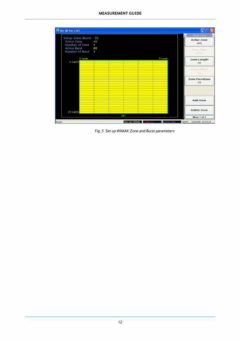
3 Configure OFDMA parameters This configuration is important for evaluating modulation quality measurements exactly. Configure WiMAX frequency and timing parameters by pressing [Setup]. Configure the link direction (Downlink or Uplink) by pressing the [F1] key. Configure zone and burst parameters by pressing [NEXT] and selecting [Edit Zone Info…]. After finishing configuration, return to the measurement menu by pressing [MEASURE].
Fig. 4 Set up WiMAX frequency & timing parameters
MEASUREMENT GUIDE
12
Fig. 5 Set up WiMAX Zone and Burst parameters

13
802.16e signal measurement guide
This chapter gives guidance for measuring the physical layer performance of a WiMAX (802.16e) signal. It describes a typical procedure for each measurement of a WiMAX signal. The target system (BS or MS) of this measurement option must follow the IEEE 802.16e OFDMA standard, released in 2005.
OFDMA basic theory
Orthogonal Frequency Division Multiplexing Access (OFDMA) is an access technique that sub-divides the bandwidth into multiple frequency subcarriers. Fig. 6 gives a simple description for the multi-carrier modulation method of an OFDMA system. In an OFDMA system, the input data stream is divided into several parallel sub-streams with reduced data rate (increasing symbol duration). Each sub-stream is modulated and transmitted on a separate orthogonal subcarrier. The increased symbol duration improves the robustness of OFDMA to delay spread.
Fig. 6 Description of OFDMA modulation
Furthermore, the introduction of the cyclic prefix (CP) can completely eliminate inter-symbol interference (ISI) as long as the CP duration is longer than the channel delay spread. The CP is typically a repetition of the last samples of the data portion of the block, which are appended to the beginning of the data payload as shown in Fig. 7.
The CP prevents inter-block interference, makes the channel appear circular, and permits low-complexity frequency domain equalization. A perceived drawback of CP is that it introduces overhead, which effectively reduces bandwidth efficiency. While the CP does reduce bandwidth efficiency somewhat, the impact of the CP is similar to the ‘roll-off factor’ in raised-cosine filtered single-carrier systems.
Fig. 7 CP (Cyclic Prefix) concept

MEASUREMENT GUIDE
14
Fig. 8 Eliminating ISI by CP
The OFDMA symbol is composed of three types of subcarrier, as shown in Fig. 9: data subcarriers for data transmission, pilot subcarriers for estimation and synchronization purposes, and null subcarriers for no transmission, together with guard bands and DC carriers
Active (data and pilot) subcarriers are grouped into subsets of subcarriers called sub-channels. The WiMAX OFDMA PHY [3] supports sub-channelization in both DL and UL.
Fig. 9 OFDMA subcarriers
WiMAX and 802.16e standard
The IEEE 802.16 group produced 802.16a, to include NLOS applications in the 2 GHz–11 GHz band, using an orthogonal frequency division multiplexing (OFDM)-based physical layer. Additions to the MAC layer, such as support for orthogonal frequency division multiple access (OFDMA), were also included. Further revisions resulted in a new standard in 2004, called IEEE 802.16-2004, which replaced all prior versions and formed the basis for the first WiMAX solution. These early WiMAX solutions, based on IEEE 802.16-2004, targeted fixed applications, and we refer to these as ‘fixed WiMAX’.
In 2005, the IEEE group completed and approved IFEEE 802.16e-2005, an amendment to the IEEE 802.16-2004 standard that added mobility support. IEEE 802.16e-2005 forms the basis for the WiMAX solution for nomadic and mobile applications and is often referred to as ‘mobile WiMAX’. The basic characteristics of the various IEEE 802.16 standards are summarized in Table 1.

MEASUREMENT GUIDE
15
Table 1 IEEE-802.16 basic parameters
802.16-2004 802.16e-2005
Frequency band 2 GHz ~ 11 GHz 2 GHz–11 GHz for fixed;
2 GHz–6 GHz for mobile applications
Application Fixed NLOS Fixed and mobile NLOS
MAC architecture Point to multipoint mesh Point to multipoint mesh
Transmission scheme Single carrier,
256 OFDM or 2,048 OFDM
Single carrier, 256 OFDM or scalable OFDM with 128, 512, 1,024, or 2,048 subcarriers
Modulation QPSK, 16QAM, 64QAM QPSK, 16QAM, 64QAM
Gross rata rate 1 Mbps ~ 75 Mbps 1 Mbps ~ 75 Mbps
Multiplexing Burst TDM/TDMA/OFDMA Burst TDM/TDMA/OFDMA
Duplexing TDD and FDD TDD and FDD
Channel bandwidth 1.75 MHz, 3.5 MHz, 7 MHz, 14 MHz, 1.25 MHz, 5 MHz, 10 MHz, 15 MHz, 8.75 MHz
1.75 MHz, 3.5 MHz, 7 MHz, 14 MHz, 1.25 MHz, 5 MHz, 10 MHz, 15 MHz, 8.75 MHz
Definition of mobile WiMAX basic parameters Mobile WiMAX, which is based on the IEEE 802.16e-2005 standard, uses a scalable OFDMA-based physical layer. In the case of mobile WiMAX, the FFT sizes can vary from 128 bits to 2,048 bits. The terms described here follow the IEEE 802.16e-2005 standard.
Primitive parameters definitions BW: this is the nominal channel bandwidth.
Nused: number of used subcarriers (which includes the DC subcarrier).
n: sampling factor. This parameter, in conjunction with BW and Nused, determines the subcarrier spacing and the useful symbol time. This value is set to 8/7 as follows: for channel bandwidths that are a multiple of 1.75 MHz, n = 8/7. For channel bandwidths that are a multiple of any of 1.25, 1.5, 2 or 2.75 MHz, n = 28/25. For channel bandwidths not otherwise specified n = 8/7.
G: this is the ratio of CP time to ‘useful’ time. The following values are supported: 1/32, 1/16,1/8, and 1/4.
Definition of slot The definition of an OFDMA slot depends on the OFDMA symbol structure, which varies for uplink and downlink, for FUSC and PUSC, and for the distributed subcarrier permutations and the adjacent subcarrier permutation.
For downlink FUSC and downlink optional FUSC using the distributed subcarrier permutation, one slot is one sub-channel by one OFDMA symbol.
For downlink PUSC using the distributed subcarrier permutation, one slot is one sub-channel by two OFDMA symbols.
For uplink PUSC using either of the distributed subcarrier permutations, and for downlink TUSC1, one slot is one sub-channel by three OFDMA symbols.
For the adjacent subcarrier permutation, one slot is one sub-channel by two, three, or six OFDMA symbols.

MEASUREMENT GUIDE
16
Mobile WiMAX (802.16e) physical parameters In Mobile WiMAX, the FFT size is scalable from 128 to 2,048. Here, when the available bandwidth increases, the FFT size is also increased such that the subcarrier spacing is always 10.94 kHz. This keeps the OFDM symbol duration, which is the basic resource unit, fixed and therefore scaling has minimal impact on higher layers. A scalable design also keeps the costs low. The subcarrier spacing of 10.94 kHz was chosen as a good balance between satisfying the delay spread and Doppler spread requirements for operating in mixed fixed and mobile environments. This subcarrier spacing can support delay-spread values up to 20 µs and vehicular mobility up to 125 km/h when operating in 3.5 GHz. A subcarrier spacing of 10.94 kHz implies that 128, 512, 1,024, and 2,048 FFT are used when the channel bandwidth is 1.25 MHz, 5 MHz, 10 MHz, and 20 MHz, respectively. It should, however, be noted that mobile WiMAX may also include additional bandwidth profiles (see the column in italics in Table 2). For example, a profile compatible with WiBro will use an 8.75 MHz channel bandwidth and 1,024 FFT. This obviously requires a different subcarrier spacing and hence does not have the same scalability properties.
Table 2 IEEE-802.16e time, frequency parameters
Parameters Values
System BW (MHz) 1.25 5 10 20 3.5 7 8.75
Sampling factor 28/25 8/7
Sampling frequency (Fs,MHz)
1.4 5.6 11.2 22.4 4 8 10
Sampling time (1/Fs,nsec) 714.3 178.6 89.3 44.6 250 125 100
FFT size (NFFT) 128 512 1024 2048 512 1024 1024
Subcarrier frequency
spacing (∆ f,kHz)
10.9375 7.8125 9.765625
Useful symbol time
(Tb=1/∆ f,us) 91.4 128 102.4
Guard time (Tg=Tb/8) 11.4 16 12.8
OFDMA symbol time
(Ts=Tb+Tg,us) 102.8 144 115.2
Mobile WiMAX (802.16e) frame structure (in TDD operation mode) The 802.16e standard supports TDD (Time Division Duplex) and Full and Half-Duplex FDD (Frequency Division Duplex) operation. With ongoing releases, FDD profiles will be considered by the WiMAX Forum to address specific market opportunities where local spectrum regulatory requirements either prohibit TDD or are more suitable for FDD deployments.

MEASUREMENT GUIDE
17
Even TDD operation requires system-wide synchronization; TDD is the preferred duplexing mode for the following reasons:
TDD enables adjustment of the downlink/uplink ratio to efficiently support asymmetric downlink/uplink traffic, while with FDD, downlink and uplink always have fixed and generally, equal DL and UL bandwidths.
TDD assures channel reciprocity for better support of link adoption, MIMO and other closed-loop advanced antenna technologies.
Unlike FDD, which requires a pair of channels, TDD only requires a single channel for both downlink and uplink, providing greater flexibility for adapting to varied global spectrum allocations.
Transceiver designs for TDD implementations are less complex and therefore less expensive.
Fig. 10 illustrates the OFDM frame structure in TDD (Time Division Duplex) mode implementation. Each frame is divided into DL and UL sub-frames separated by Transmit/Receive and Receive/Transmit Transition Gaps (TTG and RTG, respectively) to prevent DL and UL transmission collisions. In a frame, the following control information is used to ensure optimal system operation:
Preamble: the preamble, used for synchronization, is the first OFDM symbol of the frame.
Frame Control Header (FCH): the FCH follows the preamble. It provides the frame configuration information such as MAP message length and coding scheme and usable sub-channels.
DL-MAP and UL-MAP: the DL-MAP and UL-MAP provide sub-channel allocation and other control information for the DL and UL sub-frames respectively.
UL Ranging: the UL ranging sub-channel is allocated for mobile stations (MS) to perform closed-loop time, frequency, and power adjustment as well as bandwidth requests.
Fig. 10 Example of an OFDMA frame in TDD mode

MEASUREMENT GUIDE
18
WiMAX transmitter test (spectrum & power)
Spectrum measurement This measurement shows the spectrum analysis result based on the FFT method. This mode of spectrum is a free-run mode of operation.
Fig. 11 FFT measurement (802.16e DL signal)
Power vs time This measurement shows OFDMA burst characteristics in the time domain. Its measurement can be gated on and off by the S/W trigger method, based on its burst information, which you set: so the ‘Power vs Time’ measurement can be seen in either ‘free run’ or ‘gated’ mode.

MEASUREMENT GUIDE
19
Fig. 12 Power vs Time in gated mode (802.16e DL signal)
Fig. 13 Power vs Time in Free run mode (802.16e UL signal)

MEASUREMENT GUIDE
20
CCDF The CCDF (Complementary Cumulative Distribution Function) of the transmit output power is another important measurement of WiMAX transmitter quality. Because OFDM signals tend to exhibit high peak-to-average ratios, due to the AM of the subcarriers, CCDF measurements can help analyze WiMAX transmitter or power amplifier performance.
CCDF shows the distribution of peak-to-average power ratio (PAPR) versus the probability of a particular peak level occurring. Time gating is essential when making CCDF measurements on the OFDMA signal. The CCDF can be seen simultaneously with the power vs time measurement. It can be time-gated, and you can vary its time-gate position and length.
As can be seen in Fig. 14, the CCDF measurement area can be set for its start time and interval as specified ‘t1’ and ‘t2’. Specifically, Fig. 14 shows the CCDF measurement for the 802.16e (Downlink) preamble area (one symbol length) and Fig. 15 shows the CCDF measurement for the data burst area (two symbol length). The different measurement result is derived from its different modulation method (preamble is modulated with BPSK and data burst modulated with QPSK or QAM modulation method).
Fig. 14 CCDF measurement (802.16e DL signal, Preamble)

MEASUREMENT GUIDE
21
Fig. 15 CCDF measurement (802.16e DL signal, Data burst)
Power vs time with crest factor The crest factor, or peak-to-average ratio (PAR), or peak-to-average power ratio (PAPR), is a measurement of a waveform, calculated from the peak amplitude of the waveform divided by the RMS (time-averaged) value of the waveform. It is therefore a dimensionless quantity (dB scale).
For a burst signal, the crest factor can be divided into burst crest factor and normal crest factor. Burst crest factor can be measured in ‘Gate On’ mode, while normal crest factor can be measured in the ‘Gate Off’ mode of operation. Similarly to the previous measurement, you can vary the time gate position and length: it is specified by ‘t1’ and ‘t2’ as shown in Fig. 16 and Fig. 17.
Fig. 16 shows the crest factor measurement result for preamble and Fig. 17 shows the data burst area; as it has a different modulation scheme its crest factor is different to its area of burst.

MEASUREMENT GUIDE
22
Fig. 16 Crest factor measurement (802.16e DL signal, Preamble)
Fig. 17 Crest factor measurement (802.16e DL signal, Data burst)
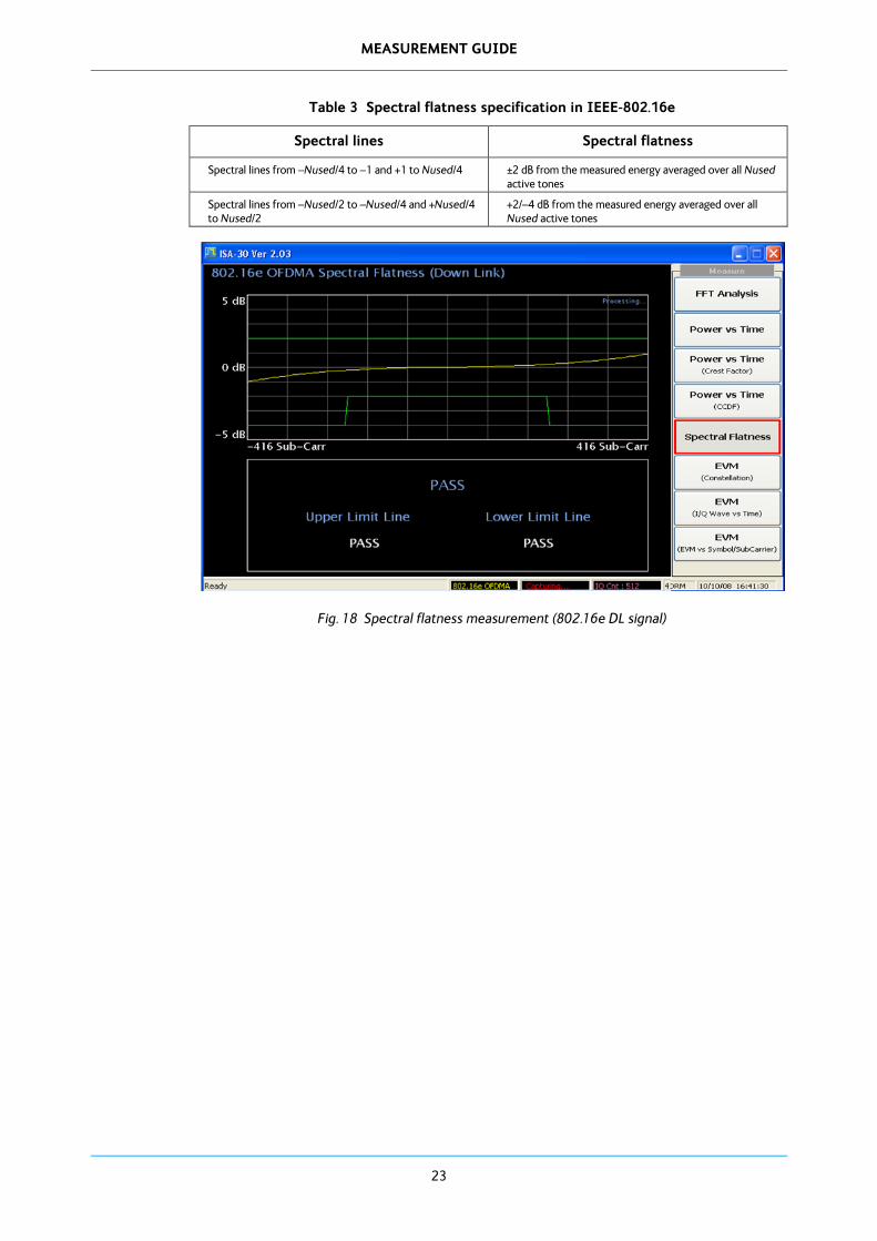
Spectral flatness Spectral flatness is a measure of the consistency in power level of the subcarriers that compose a WiMAX OFDMA signal. As specified in the WiMAX specification (IEEE -802.16e), adjacent subcarriers are required to be within 0.1 dB in amplitude level. Some deviation is assumed in the overall levels of the carrier, with a window defined by the standard. The close-in or inner one-half subcarriers in a WiMAX burst signal should be within ±2 dB of the average power level of the burst signal, while the outer one-half of the subcarriers should be within +2 and –4 dB of the average power level of the burst signal. IEE 802.16e specifies this regulation of spectral flatness as shown in Table 3.
MEASUREMENT GUIDE
23
Table 3 Spectral flatness specification in IEEE-802.16e
Spectral lines Spectral flatness
Spectral lines from –Nused/4 to –1 and +1 to Nused/4 ±2 dB from the measured energy averaged over all Nused active tones
Spectral lines from –Nused/2 to –Nused/4 and +Nused/4 to Nused/2
+2/–4 dB from the measured energy averaged over all Nused active tones
Fig. 18 Spectral flatness measurement (802.16e DL signal)

MEASUREMENT GUIDE
24
WiMAX transmitter test (modulation quality)
Configuration for modulation quality measurement To get an appropriate measurement result for modulation quality, you must set the exact value for various frequency, timing and frame parameters for the WiMAX signal. There are two methods given in this WiMAX option for setting these parameters. First, you only need to select the standard with its bandwidth parameters (5 MHz std, 7 MHz Std, 8.75 MHz Std, 10 MHz Std). These parameters can be referenced in Table 2, and are specified in the IEEE 802.16e standard. The parameters are as below:
Bandwidth: 1.25 MHz, 3.5 MHz, 4.375 MHz, 5 MHz, 7 MHz, 8.75 MHz (default), 10 MHz, 20 MHz
FFT size: 128, 512, 1024 (default), 2048
Guard period: 1/4, 1/8 (default), 1/16, 1/32
Frame duration: 2.5 ms, 4 ms, 5 ms (default), 8 ms, 10 ms, 12.5 ms
Fig. 19 shows an 802.16e 10MHz standard signal example for configuring link direction and frequency and timing parameters in EVM measurement mode.
Go to this menu by pressing [Mode]. [NEXT], [802.16 OFDMA], [Setup].
Fig. 19 Set frequency and timing parameters (802.16e DL signal)

MEASUREMENT GUIDE
25
In addition to setting frequency and timing parameters, zone and burst parameters can be configured by selecting [More 1 of 2] in Fig. 19. The zone parameters are as below:
Zone number (active zone)
Zone type
Zone length
Zone offset
Permutation base
Fig. 20 gives a simple example for zone configurations.
Go to this menu by pressing [Mode]. [NEXT], [802.16 OFDMA], [Setup], [NEXT], [Edit Zone Info].
Fig. 20 Set parameters for zone (802.16e DL signal)
Burst zone parameters are as below:
Burst number (active burst)
Burst symbol number
Burst sub-channel number
Burst symbol offset
Burst modulation type: QPSK, 16QAM, 64QAM

MEASUREMENT GUIDE
26
Fig. 21 gives a simple example for burst configurations. Burst can be added by selecting [Add Burst] and can be deleted by select [Delete Burst]. Go to this menu by pressing [Mode]. [NEXT], [802.16 OFDMA], [Setup], [NEXT], [Edit Zone Info], [NEXT].
Fig. 21 Set parameters for Burst (802.16e DL signal)

MEASUREMENT GUIDE
27
EVM measurement Modulation accuracy is the relative difference between a received signal constellation point and its ideal constellation point. As noted above, the measurement is carried out on both modulated and unmodulated carriers to ensure that the MS does not degrade the link for itself or other users. The equalizer is set to operate on pilots, and remove amplitude, phase, and timing errors, thereby matching the expected capability of a BS receiver.
To measure EVM, go to [Mode]. [NEXT], [802.16 OFDMA], [MEASURE], [EVM].
Fig. 22 Measuring EVM for WiMAX signal (802.16e DL signal)
Constellation measurement There are three modulation types available for modulating the data onto the subcarriers: QPSK, 16QAM, and 64QAM. In the UL, the transmit power is automatically adjusted when the modulation coding sequence (MCS) changes to maintain the required nominal carrier-to-noise ratio at the BS receiver. 64QAM is not mandatory for the UL. Binary phase shift keying (BPSK) modulation is used during the preamble, on the pilots, and when modulating subcarriers in the ranging channel.
The IEEE-802.16e standard defines the allowed relative constellation error (RCE) as you can see in Table 4.
This constellation measurement separates modulation burst by color. Fig. 23 shows two type of modulation, one is BPSK (preamble) and the other is QPSK (data burst).
To measure constellation, go to [Mode]. [NEXT], [802.16 OFDMA], [MEASURE], [Constellation].
Table 4 Allowed relative constellation error versus data rate
Burst type Relative constellation for SS (dB)
Relative constellation for BS (dB)
QPSK-1/2 -15 -15
QPSK-3/4 -18 -18
16-QAM-1/2 -20.5 -20.5
16-QAM -3/4 -24 -24
64-QAM-1/2 -26 -26
64-QAM-2/3 -28 -28

MEASUREMENT GUIDE
28
64-QAM-3/4 -30 -30
Fig. 23 Measuring constellation for WiMAX signal (802.16e DL signal)
Frequency error measurement At the SS, both the transmitted center frequency and the sampling frequency are derived from the same reference oscillator. The SS uplink transmission is locked to the BS, so that its center frequency deviates no more than 2% of the subcarrier spacing, compared to the BS center frequency.
In the case of an 8.75 MHz BW WiMAX signal (WiBro), the subcarrier spacing is 9.765625 kHz. This means that the allowed transmitter frequency error must be less than 195.3125 Hz. This measurement can be seen on EVM and constellation measurements with modulation quality parameters.
29
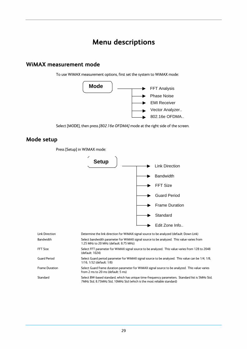
Menu descriptions
WiMAX measurement mode
To use WiMAX measurement options, first set the system to WiMAX mode:
Mode FFT Analysis
Phase Noise EMI Receiver
Vector Analyzer.. 802.16e OFDMA..
Select [MODE], then press [802.16e OFDMA] mode at the right side of the screen.
Mode setup
Press [Setup] in WIMAX mode:
Setup Link Direction
Bandwidth
FFT Size
Guard Period
Frame Duration
Standard
Edit Zone Info.. Link Direction Determine the link direction for WiMAX signal source to be analyzed (default: Down Link)
Bandwidth Select bandwidth parameter for WiMAX signal source to be analyzed. This value varies from 1.25 MHz to 20 MHz (default: 8.75 MHz)
FFT Size Select FFT parameter for WiMAX signal source to be analyzed. This value varies from 128 to 2048 (default: 1024)
Guard Period Select Guard period parameter for WiMAX signal source to be analyzed. This value can be 1/4, 1/8, 1/16, 1/32 (default: 1/8)
Frame Duration Select Guard frame duration parameter for WiMAX signal source to be analyzed. This value varies from 2 ms to 20 ms (default: 5 ms)
Standard Select BW-based standard, which has unique time-frequency parameters. Standard list is 5MHz Std, 7MHz Std, 8.75MHz Std, 10MHz Std (which is the most reliable standard)

MENU DESCRIPTIONS
30
Edit Zone Info
Set the zone and burst parameters that specify the input WiMAX signal.
Zone configuration parameters:
Active Zone: Current activated zone
Zone Type: PUSC
Zone offset
Zone Permutation Base
Burst configuration parameters
Active burst: Current activated burst
Burst symbols
Burst subchannel
Burst symbol offset
Burst subchannel offset
Burst modulation type: QPSK, 16QAM, 32QAM
Frequency menu Press [FREQ] in WiMAX mode:
Center Frequency FREQ
You can access frequency functions from this menu.
Center Frequency Set to center frequency: 1 kHz to 3 / 8 / 13.2 / 26.5 GHz
Span menu (FFT analysis only) Press [SPAN] in WiMAX mode:
SPAN SPAN
SPAN Set to span frequency: 100 kHz to 30 MHz.
Amplitude menu Press [AMPL] in WiMAX mode:
AMPL Ref. Level
Scale/Div
Attenuator Lev
IQ Scale Max
Ref Offset Amplitude menu keys are used for setting functions that affect the way data on the vertical axis is displayed or corrected.
Ref. Level This allows you to set the value in dBc/Hz of a specified position on the graticule display.
Scale/Div This allows you to set the value of scale in dB for each division of Y-axis.
Attenuator Lev This allows you to set the internal attenuator level in dB.
IQ Scale Max This allows you to set the value of I/Q scale of Y-axis.
Ref Offset Sets the offset value for the displayed signal.

MENU DESCRIPTIONS
31
Measure menu Press [MEAS] in WiMAX mode:
MEAS FFT Analysis
Power vs Time
Spectral Flatness
I/Q Wave & Constellation
EVM
CCDF
Constellation
FFT Analysis Analyzes a WiMAX signal in spectrum mode.
Power vs Time Measures power vs time of a WiMAX signal.
Spectral Flatness Measures the spectral flatness of a WIMAX signal for its sub-carrier. The Pass/Fail result for carrier flatness is measured and displayed (refer IEEE 802.16e Std).
Constellation Measures the constellation diagram for a WIMAX input signal. The modulation-related numerical result is shown on the left side of the window.
I/Q wave & Constellation
Shows the constellation result simultaneously with its I/Q wave versus time.
EVM Measure the Error Vector Magnitude for a WIMAX input signal. ‘EVM vs Symbols’ and ‘EVM vs Sub-carriers’ are shown.
CCDF Measures the CCDF (Complementary Cumulative Distribution Function) of the WiMAX signal.
Measure control menu (except FFT analysis) Press [CONTROL] in WiMAX mode:
Control
Capture Time
Capture Time Specifies the time to be captured for I/Q analysis. The maximum capture time differs according to the sampling rate.

MENU DESCRIPTIONS
32
Marker menu (FFT analysis only) Press [MARKER] in WiMAX mode:
Marker
Select Marker
Normal
Delta
OFF
All OFF
Select Marker Allows you to select one of the four possible markers. Having selected one of the markers, use the other soft keys on this menu to specify the type of marker or measurement.
Normal Sets the specified marker to be a normal marker.
Delta A delta marker is actually a pair of markers. By pressing Delta, you set a pair of markers at your current frequency offset. One of this pair of markers is fixed while the second of the pair can be moved using the scroll knob or the numeric keys. The frequency difference and the amplitude difference between these two points is displayed.
OFF Switches the specified marker off.
All OFF Switches all markers off. All markers are removed from the graticule display, and if the marker table is also being displayed, all entries are removed from it.
Peak menu (FFT analysis only) Press [PEAK] in WiMAX mode:
Peak
Peak
Next Peak
Peak Sets active marker to max level of FFT trace.
Next Peak Sets active marker to next max level of FFT trace.
Display menu Press [Display] in WiMAX mode:
Display
White Mode
Graticule
White Mode Change the screen background to white.
Graticule Allows you to display or hide the graticule lines on the display.

MENU DESCRIPTIONS
33
Sweep menu Press [Sweep] in WiMAX mode:
Sweep
Single
Continuous
Single The analyzer performs one single measurement and then stops. You have to press [Restart]
every time you want to make another measurement.
Continuous The analyzer continuously measures the signal it is receiving and repeatedly updates the plots and the measurements.
BW menu Press [BW] in WiMAX mode:
BW RBW Manual/Auto
RBW
RBW Manual/Auto Sets RBW mode to manual or auto. In Auto mode, RBW is set automatically to Span/100.
RBW Set to RBW value (1 kHz to 300 kHz).
Trace menu (FFT analysis only) Press [TRACE] in WiMAX mode:
Trace Max Hold
Average
AVG. Count
Max Hold Trace level is maximum level.
Average Trace level is averaged. The trace is then smoothed.
Avg. Count Set to the average count (2 to 1000).
Preset menu Press [Preset] in WiMAX mode:
Preset Preset
The sub menus of [Preset] have the same function as in the basic spectrum analysis mode. Please refer to the Spectrum Analyzer Operating Manual (part number 46892/974) for other soft key functions.

34
Detailed description of commands
General
This section gives detailed descriptions of the device messages for the spectrum analyzer in functional order. The following example shows the command format.
Note that ‘△’ = ‘blank’ throughout this document.
SA command
SCPI command Command Name
Function The explanation of the command.
Remote Command SA Command△sw
SA Command△f
SA Command?
SCPI Command△sw
SCPI Command△f
SCPI Command?
Response Message sw or f
(Depending on command)
Value of f Range of sw or f
(Depending on command)
Suffix code Unit of f
(Depending on command)
Initial setting Initial value for SA System
Example SA Command sw;
SA Command f;
SA Command?;
SCPI Command sw;
SCPI Command f;
SCPI Command?;

DETAILED DESCRIPTION OF COMMANDS
35
Amplitude
RL
:DISPlay:WINDow:TRACe:Y[:SCALe]:RLEVel Reference Level
Function Sets the reference level value.
Remote Command RL△f
RL?
:DISPlay:WINDow:TRACe:Y[:SCALe]:RLEVel△f
:DISPlay:WINDow:TRACe:Y[:SCALe]:RLEVel?
Response Message Reference Level (dBm)
Value of f −170 dBm to 30 dBm (Step : 0.01 dBm)
Suffix code None : dBm
DBM : dBm
Initial setting 0 dBm
Example RL 10;
RL 30DBM;
RL ?;
DISP:WIND:TRAC:Y:RLEV 10;
DISP:WIND:TRAC:Y:RLEV 30DBM;
DISP:WIND:TRAC:Y:RLEV?;

DETAILED DESCRIPTION OF COMMANDS
36
AT
[:SENSE]:POWer[:RF]:ATTenuation Attenuation
Function Sets the amount of attenuation for the input attenuator.
Remote Command AT△f
AT?
[:SENSe]:POWer[:RF]:ATTenuation△f
[:SENSe]:POWer[:RF]:ATTenuation?
Response Message amount of attenuation (dB)
Value of f 0 dB to 55 dB (Step : 5 dB)
Suffix code None : dB
DB : dB
Initial setting 10 dB
Example AT 10;
AT 10DB;
AT?;
POW:ATT 10;
POW:ATT 10DB;
POW:ATT?;

DETAILED DESCRIPTION OF COMMANDS
37
SD
:DISPlay:LPLot:WINDow:TRACe:Y[:SCALe]:PDIVision Scale/Divide
Function Sets the scale/divide value.
Remote Command SD△f
SD?
:DISPlay:LPLot:WINDow:TRACe:Y[:SCALe]:PDIVision△f
:DISPlay:LPLot:WINDow:TRACe:Y[:SCALe]:PDIVision?
Response Message Scale/Divide (dB/div)
Value of f 0.01 dB to 20 dB (step : 0.01 dB)
Suffix code None : dB/div
DB : dB/div
Initial setting 10 dB/div
Example SD 5;
SD 10DB;
SD?;
DISP:LPL:WIND:TRAC:Y:PDIV 5;
DISP:LPL:WIND:TRAC:Y:PDIV 10DB;
DISP:LPL:WIND:TRAC:Y:PDIV?;

DETAILED DESCRIPTION OF COMMANDS
38
Average (FFT Analysis Only)
AVG
[:SENSe]:AVERage[:STATe] Average
Function Turns the trace average to on or off. Depends on the condition of the average count and the average mode.
Remote Command AVG△n
AVG△sw
AVG?
[:SENSe]:AVERage[:STATe]△n
[:SENSe]:AVERage[:STATe]△sw
[:SENSe]:AVERage[:STATe]?
Response Message 1 : ON
0 : OFF
Value of n 1 : ON
0 : OFF
Value of sw ON : ON
OFF : OFF
Initial setting 0
Example AVG 1;
AVG ON;
AVG?;
AVER 1;
AVER ON;
AVER?;

DETAILED DESCRIPTION OF COMMANDS
39
AVGC
[:SENSe]:AVERage:COUNt Average Count
Function Sets the averaging count.
Remote Command AVGC△n
AVGC?
[:SENSe]:AVERage:COUNt△n
[:SENSe]:AVERage:COUNt?
Response Message Average count
Value of n 2 to 1000
Initial setting 100
Example AVGC 30;
AVGC?;
AVER:COUN 30;
AVER:COUN?;

DETAILED DESCRIPTION OF COMMANDS
40
Bandwidth (FFT analysis only)
RB
[:SENSe]:BANDwidth|BWIDth[:RESolution] Resolution Bandwidth
Function Sets the NBW value.
Remote Command RB△f
RB?
[:SENSe]:BANDwidth|BWIDth[:RESolution]△f
[:SENSe]:BANDwidth|BWIDth[:RESolution]?
Response Message Resolution Bandwidth (Hz)
Value of f 1 kHz to 300 kHz / 1 MHz / 2 MHz (Step : 10 Hz)
Suffix code f None : Hz (10^0)
HZ : Hz (10^0)
KHZ : kHz (10^3)
MHZ : MHz (10^6)
GHZ : GHz (10^9)
Initial setting Span/100
Example RB 1000;
RB 3KHZ;
RB?
BAND 1000;
BAND 3KHZ;
BAND?;

DETAILED DESCRIPTION OF COMMANDS
41
RBA
[:SENSe]:BANDwidth|BWIDth[:RESolution]:AUTO Resolution Bandwidth Auto
Function Sets the NBW mode to the auto mode or the manual mode.
Remote Command RBA△n
RBA△sw
RBA?
[:SENSe]:BANDwidth|BWIDth[:RESolution]:AUTO△n
[:SENSe]:BANDwidth|BWIDth[:RESolution]:AUTO△sw
[:SENSe]:BANDwidth|BWIDth[:RESolution]:AUTO?
Response Message 1 : ON
0 : OFF
Value of n 1 : ON
0 : OFF
Value of sw ON : ON
OFF : OFF
Initial setting 1
Example RBA 1;
RBA ON;
RBA?
BAND:AUTO 1;
BAND:AUTO ON;
BAND:AUTO?;

DETAILED DESCRIPTION OF COMMANDS
42
Display
GRAT
:DISPlay:WINDow:TRACe:GRATicule:GRID[:STATe] Graticule
Function Sets the display graticule to Type1 or Type2 or OFF.
Remote Command GRAT△sw
GRAT?
:DISPlay:WINDow:TRACe:GRATicule:GRID[:STATe]△sw
:DISPlay:WINDow:TRACe:GRATicule:GRID[:STATe]?
Response Message TYPE1 : Type1
TYPE2 : Type2
OFF : OFF
Value of sw TYPE1 : Type1
TYPE2 : Type2
OFF : OFF
Initial setting TYPE1
Example GRAT TYPE1;
GRAT?
DISP:WIND:TRAC:Y:GRAT:GRID TYPE1;
DISP:WIND:TRAC:Y:GRAT:GRID?;

DETAILED DESCRIPTION OF COMMANDS
43
WH
:DISPlay:WINDow:WHITe White Mode
Function Turns the white mode ON or OFF.
Remote Command WH△n
WH△sw
WH?
:DISPlay:WINDow:WHITe△n
:DISPlay:WINDow:WHITe△sw
:DISPlay:WINDow:WHITe?
Response Message 1 : ON
0 : OFF
Value of n 1 : ON
0 : OFF
Value of sw ON : ON
OFF : OFF
Initial setting 0
Example WH 1;
WH ON;
WH?
DISP:WIND:WHIT 1;
DISP:WIND:WHIT ON;
DISP:WIND:WHIT?;

DETAILED DESCRIPTION OF COMMANDS
44
File
FREAD
:MMEMory:CATalog File Read
Function Reads files in the selected folder.
Remote Command FREAD?△‘file_folder’
:MMEMory:CATalog?△‘file_folder’
Value of file_folder File Folder
Response Message File Name,,File Size.
Example FREAD? ‘C:’;
FREAD? ‘D:\Temp’;
MMEM:CAT? ‘C:’;
MMEM:CAT? ‘D:\Temp’;

DETAILED DESCRIPTION OF COMMANDS
45
FSAVE
:MMEMory:STORe File Save
Function Saves the file, type defined by the extension.
Remote Command FSAVE△‘file_name’
:MMEMory:STORe△‘file_name’
Value of file_name File Path + File Name
Supported Extension csv : I/Q data
bmp : Bitmap
jpg : jpeg
png : png
zon : Zone/Burst
Example FSAVE ‘C:\demo.zon’;
MMEM:STRO ‘C:\demo.zon’;

DETAILED DESCRIPTION OF COMMANDS
46
FLOAD
:MMEMory:LOAD File Load
Function Loads the selected file.
Remote Command FLOAD△‘file_name’
:MMEMory:LOAD△‘file_name’
Value of file_name File Path + File Name
Supported Extension zon : Zone/Burst
Example FLOAD ‘C:\demo.zon’;
MMEM:LOAD ‘C:\demo.zon’;

DETAILED DESCRIPTION OF COMMANDS
47
FDEL
:MMEMory:DELete File Delete
Function Deletes the selected file.
Remote Command FDEL△‘file_name’
:MMEMory:DELete△‘file_name’
Value of file_name File Path + File Name
Example FDEL ‘C:\demo.bmp’;
MMEM:DEL ‘C:\demo.bmp’;

DETAILED DESCRIPTION OF COMMANDS
48
FCOPY
:MMEMory:COPY File Copy
Function Copies the selected file.
Remote Command FCOPY△‘src_file_name’, ‘dest_file_name’
:MMEMory:COPY△‘src_file_name’, ‘dest_file_name’
Value of src_file_name, dest_file_name File Path + File Name
Example FCOPY ‘C:\demo.bmp’,‘D:\demo.bmp’;
MMEM:COPY ‘C:\demo.bmp’,‘D:\demo.bmp’;

DETAILED DESCRIPTION OF COMMANDS
49
FRENAME
:MMEMory:MOVE File Rename
Function Renames the selected file.
Remote Command FRENAME△‘src_file_name’,‘dest_file_name’
:MMEMory:MOVE△‘src_file_name’,‘dest_file_name’
Value of src_file_name, dest_file_name File Path + File Name
Example FRENAME ‘C:\demo.bmp’,‘C:\demo1_1.bmp’;
MMEM:MOVE ‘C:\demo1.bmp’,‘C:\demo1_1.bmp’;

DETAILED DESCRIPTION OF COMMANDS
50
FMOVE
MMEMory:DATA File Move
Function Sends or receives binary data of the selected file. The maximum size of the sent file is 2 Mbyte, and the maximum size of the received file is 30 Mbyte.
Remote Command FMOVE△‘file_name’,definite_length_block
FMOVE?△‘file_name’
MMEMory:DATA△‘file_name’,definite_length_block
MMEMory:DATA?△‘file_name’
Value of file_name File Path + File Name
Value of definite_length_block # + number of file size + file size + file data
Example FMOVE ‘C:\Sended_Sample.txt’,#14abcd; cf) #+1+4+abcd
FMOVE? ‘C:\Received_Sample.txt’;
MMEM:DATA ‘C:\ Sended_Sample.txt’,#14abcd;
MMEM:DATA? ‘C:\ Received_Sample.txt’;

DETAILED DESCRIPTION OF COMMANDS
51
Frequency
CF
[:SENSe]:FREQuency:CENTer Center Frequency
Function Sets the center frequency.
Remote Command CF△f
CF?
[:SENSe]:FREQuency:CENTer△f
[:SENSe]:FREQuency:CENTer?
Response Message Center Frequency (Hz)
(Range : 1 kHz to 3 / 8 / 13.2 / 26.5 GHz)
Value of f 1 kHz to 3 / 8 / 13.2 / 26.5 GHz
Suffix code None : Hz (10^0)
HZ : Hz (10^0)
KHZ : kHz (10^3)
MHZ : MHz (10^6)
GHZ : GHz (10^9)
Initial setting 1.5 / 4 / 6.6 / 12.25 GHz
Example CF 123456;
CF 50MHZ;
CF?;
FREQ:CEN7T 123456;
FREQ:CENT 50MHZ;
FREQ:CENT?;

DETAILED DESCRIPTION OF COMMANDS
52
SR
[:SENSe]:FREQuency:SAMPling:RATE Sampling Frequency
Function Sets to Sampling Rate.
Remote Command SR△f
SR?
[:SENSe]:FREQuency:SAMPLing:RATE△f
[:SENSe]:FREQuency:SAMPLing:RATE?
Response Message Sampling Rate (Hz)
(50 kHz to 52 MHz)
Suffix code None : Hz (10^0)
HZ : Hz (10^0)
KHZ : kHz (10^3)
MHZ : MHz (10^6)
Initial setting According to Span and RBW
Example USF 123456;
USF 50MHZ;
USF?;
FREQ:SAMP:RATE 123456;
FREQ:SAMP:RATE 50MHZ;
FREQ:SAMP:RATE?;
REF
:INPut:REFerence Reference
Function Sets to 10 MHz Reference.
Remote Command REF△sw
REF?
:INPut:REFerence△sw
:INPut:REFerence?
Response Message INT : Internal
EXT : External
Value of sw INTernal: Internal
EXTernal: External
Initial setting INT
Example REF INT;
RFC?
INP:REF INT;
INP:REF?

DETAILED DESCRIPTION OF COMMANDS
53
Marker (FFT analysis only)
MS[1~9]
:CALCulate:MARKer[1~9]:STATe Marker State
Function Sets the selected marker state.
Remote Command MS[1~9]△n
MS[1~9]△sw
MS[1~9]?
:CALCulate:CCDF:MARKer[1~9]:STATe△n
:CALCulate:CCDF:MARKer[1~9]:STATe△sw
:CALCulate:CCDF:MARKer[1~9]:STATe?
Response Message 1 : ON
0 : OFF
Value of n 1 : ON
0 : OFF
Value of sw ON : ON
OFF : OFF
Initial setting 0
Example MS 1;
MS5 1;
MS5?;
CALC:CCDF:MARK:STAT 1;
CALC:CCDF:MARK5:STAT ON;
CALC:CCDF:MARK5:STAT?

DETAILED DESCRIPTION OF COMMANDS
54
MM[1~9]
:CALCulate:MARKer[1~9]:MODE Marker Mode
Function Sets the selected marker to Normal, Delta Mode.
Remote Command MM[1~9]△sw
MM[1~9]?
: CALCulate:MARKer[1~9]:MODE△sw
:CALCulate:MARKer[1~9]:MODE?
Response Message POS : Normal
DELT : Delta
OFF : OFF
Value of sw POSition : Normal
DELTa : Delta
OFF : OFF
Initial setting OFF
Example MM POS;
MM5?;
CALC:CCDF:MARK:MODE POS;
CALC:CCDF:MARK5:MODE?

DETAILED DESCRIPTION OF COMMANDS
55
MF[1~9]
:CALCulate:MARKer[1~9]:X Marker Frequency
Function Sets the marker frequency of the selected marker. If the marker mode is the delta mode, sets the difference value of the marker frequency and the delta marker frequency.
Remote Command MF[1~9]△f
MF[1~9]?
:CALCulate:MARKer[1~9]:X△f
:CALCulate:MARKer[1~9]:X?
Response Message Marker Frequency (Hz)
Value of f Start Frequency to Stop Frequency
Suffix code None : Hz (10^0)
HZ : Hz (10^0)
KHZ : kHz (10^3)
MHZ : MHz (10^6)
GHZ : GHz (10^9)
Initial setting Center Frequency
Example MF 123456;
MF5.1GHZ;
MF5?;
CALC:MARK:X 123456;
CALC:MARK5:X 1GHZ;
CALC:MARK5:X?

DETAILED DESCRIPTION OF COMMANDS
56
MA[1~9]
:CALCulate:MARKer[1~9]:Y Marker Amplitude
Function Returns the amplitude data.
Remote Command MA[1~9]?
:CALCulate:MARKer[1~9]:Y?
Response Message Marker Amplitude
Example MA?;
MA5?
CALC:MARK:Y?
CALC:MARK5:Y?

DETAILED DESCRIPTION OF COMMANDS
57
MAO
:CALCulate:LPLot:MARKer:AOFF Marker All OFF
Function Turns off all markers.
Remote Command MAO
:CALCulate:LPLot:MARKer:AOFF
Example MAO;
CALC:LPL:MARK:AOFF;

DETAILED DESCRIPTION OF COMMANDS
58
Measurement
MEA
:MEASure:STARt Measure Start
Function Starts the measurement.
Remote Command MEA△sw
MEA?
:MEASure:STARt△sw
:MEASure:STARt?
Response Message FFT : FFT Analysis
PVT : Power vs Time
PVTC : Power vs Time (Crest Factor)
CCDF : Power vs Time (CCDF)
SPEC : Spectral Flatness
EVMC : EVM (Constellation)
EVMW : EVM (I/Q Wave vs Time)
EVM : EVM (EVM vs Symbol/Subcarrier)
Value of sw FFT : FFT Analysis
PVT : Power vs Time
PVTC : Power vs Time (Crest Factor)
CCDF : Power vs Time (CCDF)
SPEC : Spectral Flatness
EVMC : EVM (Constellation)
EVMW : EVM (I/Q Wave vs Time)
EVM : EVM (EVM vs Symbol/Subcarrier)
Example MEA FFT;
MEA?;
MEAS:STAR FFT;
MEAS:STAR?;
DETAILED DESCRIPTION OF COMMANDS
59
PVTOUT
:FETCh|MEASure|READ:PVTime Power vs Time Output
Function Return to results of Power vs Time.
Remote Command PVTOUT?
:FETCh|MEASure|READ:PVTime?
Response Message Burst Peak Power (dBm), Burst Average Power (dBm), Burst Length (s)
Example PVTOUT?;
MEAS:PVT?;

DETAILED DESCRIPTION OF COMMANDS
60
PVTCOUT
:FETCh|MEASure|READ:PVTime:CRESt Power vs Time (Crest Factor) Output
Function Return to results of Power vs Time (Crest Factor).
Remote Command PVTCOUT?
:FETCh|MEASure|READ:PVTime:CRESt?
Response Message Burst Peak Power (dBm), Burst Average Power (dBm), Burst Length (s), t1~t2 Peak Power (dBm), t1~t2 Average Power (dBm), t1~t2 Length (s), Crest Factor (dB)
Example PVTCOUT?;
MEAS:PVT:CRES?;

DETAILED DESCRIPTION OF COMMANDS
61
CCDFOUT
:FETCh|MEASure|READ:PVTime:CCDF Power vs Time (CCDF) Output
Function Return to results of Power vs Time (CCDF).
Remote Command CCDFOUT?
:FETCh|MEASure|READ:PVTime:CCDF?
Response Message Average Power (dBm), Average Power Percent (%), 10% Level Difference (dB), 1% Level Difference (dB), 0.1% Level Difference (dB), 0.01% Level Difference (dB), 0.001% Level Difference (dB), 0.0001% Level Difference (dB), Crest Level Difference (dB), Counts, t1~t2 Length (s)
Example CCDFOUT?;
MEAS:PVT:CCDF?;

DETAILED DESCRIPTION OF COMMANDS
62
FLATOUT
:FETCh|MEASure|READ:FLATness Spectral Flatness Output
Function Return to results of Spectral Flatness.
Remote Command FLATOUT?
:FETCh|MEASure|READ:FLATness?
Response Message All State, Upper State, Lower State
Example FLATOUT?;
MEAS:FLAT?;

DETAILED DESCRIPTION OF COMMANDS
63
EVMCOUT
:FETCh|MEASure|READ:EVM:CONSTellation EVM (Constellation) Output
Function Return to results of EVM (Constellation).
Remote Command EVMCOUT?
:FETCh|MEASure|READ:EVM:CONSTellation?
Response Message EVM RMS (dB/%), EVM Data (dB/%), EVM RMS Pilot (dB/%), EVM Peak Pilot (dB/%), EVM RMS Unmod (dB/%), EVM Peak Unmod (dB/%), Frequency Error (Hz)
Example EVMCOUT?;
MEAS:EVM:CONST?;

DETAILED DESCRIPTION OF COMMANDS
64
EVMWOUT
:FETCh|MEASure|READ:EVM:WVTime EVM (I/Q Wave vs Time) Output
Function Return to results of EVM (I/Q Wave vs Time).
Remote Command EVMCOUT?
:FETCh|MEASure|READ:EVM:WVTime?
Response Message EVM RMS (dB/%), EVM Data (dB/%), EVM RMS Pilot (dB/%), EVM Peak Pilot (dB/%), EVM RMS Unmod (dB/%), EVM Peak Unmod (dB/%), Frequency Error (Hz)
Example EVMWOUT?;
MEAS:EVM:WVT?;

DETAILED DESCRIPTION OF COMMANDS
65
EVMOUT
:FETCh|MEASure|READ:EVM EVM (EVM vs Symbol/SubCarrier) Output
Function Return to results of EVM (EVM vs Symbol/SubCarrier).
Remote Command EVMOUT?
:FETCh|MEASure|READ:EVM?
Response Message EVM RMS (dB/%), EVM Data (dB/%), EVM RMS Pilot (dB/%), EVM Peak Pilot (dB/%), EVM RMS Unmod (dB/%), EVM Peak Unmod (dB/%), Frequency Error (Hz)
Example EVMOUT?;
MEAS:EVM?;

DETAILED DESCRIPTION OF COMMANDS
66
Measurement control
MEAT
:MEASure:TIME Capturing Time
Function Sets to Capturing Time.
Remote Command MEAT△f
MEAT?
:MEASure:TIME△f
:MEASure:TIME?
Response Message Capturing Time (s)
Value of f 1 ms to max (max changes according to sampling rate)
Suffix None : s (10^0)
kSEC : ks (10^3)
SEC : s (10^0)
MSEC : ms (10^-3)
Initial setting 5 ms
Example MEAT 0.001;
MEAT 1MSEC;
MEAT?;
MEA:TIME 0.001;
MEA:TIME 1MSEC;
MEA:TIME?;

DETAILED DESCRIPTION OF COMMANDS
67
Mode
MODE
:INSTrument[:SELect] Mode
Function Sets Current Mode.
Remote Command MODE△sw
MODE?
:INSTrument[:SELect]△sw
:INSTrument[:SELect]?
Response Message SA : Spectrum Mode
VECTOR : Vector Analyzer Mode
WIMAX : WiMAX mode
Value of sw SA : Spectrum Mode
VECTOR : Vector Analyzer Mode
WimAX : WiMAX Mode
Initial setting SA
Example MODE SA;
MODE?;
INST SA;
INST?;

DETAILED DESCRIPTION OF COMMANDS
68
Mode setup
WIMAXSTD WiMAX Standard
Function Sets to WiMAX Standard.
Remote Command WIMAXSTD△sw
WIMAXSTD?
Response Message 802.16e10MHZ : 802.16e 10 MHz
802.16e8.75MHZ : 802.16e 8.75 MHz
802.16e7MHZ : 802.16e 7 MHz
802.16e5MHZ : 802.16e 5 MHz
Value of sw 802.16e10MHZ : 802.16e 10 MHz
802.16e8.75MHZ : 802.16e 8.75 MHz
802.16e7MHZ : 802.16e 7 MHz
802.16e5MHZ : 802.16e 5 MHz
Initial setting 802.16e8.75MHZ
Example WIMAXSTD 802.16e8.75MHZ;
WIMAXSTD?;

DETAILED DESCRIPTION OF COMMANDS
69
Peak search (FFT analysis only)
MPK[1~9]
:CALCulate:MARKer[1~9]:MAXimum Peak Search
Function Places the selected marker on the highest point of the marker trace.
Remote Command MPK[1~9]
:CALCulate:MARKer[1~9]:MAXimum
Example MPK;
MPK5:
CALC:MARK:MAX;
CALC:MARK5:MAX;
MPKN[1~9]
:CALCulate:MARKer[1~9]:MAXimum:NEXT Next Peak Search
Function Places the selected marker on the next highest point of the marker trace.
Remote Command MPKN[1~9]
:CALCulate:MARKer[1~9]:MAXimum:NEXT
Example x MPKN;
MPKN5:
CALC:MARK:MAX:NEXT;
CALC:MARK5:MAX:NEXT;
DETAILED DESCRIPTION OF COMMANDS
70
Preset
PRST
:SYSTem:PRESet Preset
Function Executes preset. All instrument parameters are set to default values.
Remote Command PRST
:SYSTem:PRESet
Example PRST;
SYST:PRES;

DETAILED DESCRIPTION OF COMMANDS
71
Printer
HCOPY
:HCOPy[:IMMediate] Hard Copy
Function Prints entire screen image.
Remote Command HCOPY
:HCOPy[:IMMediate]
Example HCOPY;
HCOP;

DETAILED DESCRIPTION OF COMMANDS
72
Span (FFT analysis only)
SP
[:SENSe]:FREQuency:SPAN Span
Function Sets the span.
Remote Command SP△f
SP?
[:SENSe]:FREQuency:SPAN△f
[:SENSe]:FREQuency:SPAN?
Response Message Span (Hz)
Value of f 100 kHz to 30 MHz
Suffix code None : Hz (10^0)
HZ : Hz (10^0)
KHZ : kHz (10^3)
MHZ : MHz (10^6)
Initial setting 30 MHz
Example SP 123456;
SP 30MHZ;
SP ?;
FREQ:SPAN 123456;
FREQ:SPAN 30MHZ;
FREQ:SPAN?;

DETAILED DESCRIPTION OF COMMANDS
73
Sweep
CO
:INITiate:CCDF:CONTinuous Continuous Sweep
Function Sets the continuous sweep mode. Repeats active sweep.
Remote Command CO
:INITiate:CONTinuous
Example CO;
INIT:CONT;

DETAILED DESCRIPTION OF COMMANDS
74
SI
:INITiate[:IMMediate] Single Sweep
Function Sets the single sweep mode. After activating sweep, stops sweep repeating.
Remote Command SI
:INITiate[:Immediate]
Example SI;
INIT;

DETAILED DESCRIPTION OF COMMANDS
75
System
BEEP Beep
Function Turns Beep to ON or OFF when pressing key pad..
Remote Command BEEP△n
BEEP△sw
BEEP?
Response Message 1 : ON
0 : OFF
Value of n 1 : ON
0 : OFF
Value of sw ON : ON
OFF : OFF
Initial setting 0
Example BEEP 1;
BEEP ON;
BEEP?;
ECHO Echo
Function Turns Echo to ON or OFF when controlled by hyper teminal.
Remote Command ECHO△n
ECHO△sw
ECHO?
Response Message 1 : ON
0 : OFF
Value of n 1 : ON
0 : OFF
Value of sw ON : ON
OFF : OFF
Initial setting 1
Example ECHO 1;
ECHO ON;
ECHO?;

DETAILED DESCRIPTION OF COMMANDS
76
Trace (FFT analysis only)
TRF
:TRACe:MODE Trace Status
Function Sets the trace status.
Remote Command TRF△sw
TRF?
:TRACe:MODE△sw
:TRACe:MODE?
Response Message WRIT : Clear & Wirte
MAXH : Max Hold
Value of sw WRITe : Clear & Wirte
MAXHold : Max Hold
Initial setting WRIT
Example TRF WRIT;
TRF?
TRAC:MODE WRIT;
TRAC:MODE?;

DETAILED DESCRIPTION OF COMMANDS
77
GPIB common commands
*CLS Clear Status Command
Function Clears the status byte register.
Remote Command *CLS
Example *CLS;

DETAILED DESCRIPTION OF COMMANDS
78
*ESE Standard Event Status Enable
Function Sets the standard event status enable register.
Remote Command *ESE△n
*ESE?
Response Message Register Value
Value of n 0 to 255 : Represents the sum of the bit-weighted values.
Example *ESE 20:
*ESE?;

DETAILED DESCRIPTION OF COMMANDS
79
*ESR? Standard Event Status Register Query
Function Returns the current value in the standard event status register.
Remote Command *ESR?
Response Message Register Value
Example *ESR?;

DETAILED DESCRIPTION OF COMMANDS
80
*IDN? Identification Query
Function Returns the model name, etc of the equipment
Remote Command *IDN?
Response Message Company, Model, Serial, Version
Example *IDN?;

DETAILED DESCRIPTION OF COMMANDS
81
*OPC Operation Complete Command
Function Sets the standard event register bit 0 to 1 when the requested action is complete.
Remote Command *OPC
Example *OPC;

DETAILED DESCRIPTION OF COMMANDS
82
*OPC? Operation Complete Query
Function Sets the output queue to 1 to generate a MAV summary message when all pending select device operations have completed.
Remote Command *OPC?
Response Message 1
Example *OPC?;

DETAILED DESCRIPTION OF COMMANDS
83
*RST Rest Command
Function Resets the device.
Remote Command *RST
Example *RST;

DETAILED DESCRIPTION OF COMMANDS
84
*SRE Service Request Enable Command
Function Sets the bits in the service request enable register.
Remote Command *SRE△n
*SRE?
Response Message Register Value
Value of n 0 to 255 : Represents the sum of the bit-weighted values.
Example *SRE 32;
*SRE?;

DETAILED DESCRIPTION OF COMMANDS
85
*STB? Returns Status Byte Command
Function Returns the current values of the status bytes including the MSS bit.
Remote Command *STB?
Response Message Register Value
Bit Bit Weight Bit Name Condition of status byte register
7 128 ---- 0 = Not used
6 64 MSS 0 = Service not requested
1 = Service requested
5 32 ESB 0 = Event status not generated
1 = Event status generated
4 16 MAV 0 = No data in output queue
1 = Data in output queue
3 8 ESB2 0 = Event status not generated
1 = Event status generated
2 4 ---- 0 = Not used
1 2 ---- 0 = Not used
0 1 ---- 0 = Not used
Example *STB?;

DETAILED DESCRIPTION OF COMMANDS
86
GPIB common commands — others
ESE2 Event Status Enable (End)
Function Allows the End Event Status Enable Register to select which bit in the corresponding Event Register cause a TRUE ESB summary message bit 3 when set.
Remote Command ESE2△n
ESE2?
Response Message Register Value
Value of n 0 to 255 : Represents the sum of the bit-weighted values.
Example ESE2 1;
ESE2?;

DETAILED DESCRIPTION OF COMMANDS
87
ESR2? Event Status Register (End) Query
Function Allows the sum of binary-weighted event bit values of the End Event Status Register to be read out by converting them to decimal. After readout, the End Event status Register is reset to 0.
Remote Command ESR2?
Response Message Register Value
Bit Bit Weight Event Description
7 128 Not used Not used
6 64 Not used Not used
5 32 Not used Not used
4 16 Measurement completed Measurement has completed (Peak search, OBW, X dB, Noise marker, Freq. Counter, Limit Pass/Fail..)
3 8 AUTO TUNE completed AUTO TUNE has completed.
2 4 Averaging completed Sweeping according to the specified AVERAGE number has completed.
1 2 Calibration completed Temp Cal, Pre-Filter Cal, ZNC Cal,. Level Cal.. has completed.
0 1 Sweep completed A single sweep has completed or is in standby.
Example ESR2?;

DETAILED DESCRIPTION OF COMMANDS
88
ERR
:SYSTem:ERRor[:NEXT] Error Code
Function Returns the error code of the current function. The error code is cleared.
Remote Command ERR?
Response Message Error code
Example ERR?;

89
Remote commands
< Catalog order > Index Description SA Command SCPI Command Suffix
Amplitude Ref. Level RL :DISPlay:WINDow:TRACe:Y[:SCALe]:RLEVel <amplitude>|?
Amplitude Attenuation AT [:SENSe]:POWer[:RF]:ATTenuation <amplitude>|?
Amplitude Scale/Div SD :DISPlay:WINDow:TRACe:Y[:SCALe]:PDIVision <amplitude>|?
Average Average AVG [:SENSe]:AVERage[:STATe] OFF|ON|0|1|?
Average Average Count AVGC [:SENSe]:AVERage:COUNt <integer>|?
Bandwidth Resolution Bandwidth RB [:SENSe]:BANDwidth|BWIDth[:RESolution] <frequency>|?
Bandwidth Resolution Bandwidth Auto RBA [:SENSe]:BANDwidth|BWIDth[:RESolution]:AUTO OFF|ON|0|1|?
Display Graticule GRAT :DISPlay:WINDow:TRACe:GRATicule:GRID[:STATe] OFF|ON|0|1|?
Display White Mode WH :DISPlay:WINDow:WHITe OFF|ON|0|1|?
File Read FREAD :MMEMory:CATalog ? <`directory_name'>
File Save FSAVE :MMEMory:STORe <`file_name'>
File Load FLOAD :MMEMory:LOAD <`file_name'>
File Delete FDEL :MMEMory:DELete <`file_name'>
File Copy FCOPY :MMEMory:COPY <`file_name1'>,<`file_name2'>
File Rename FRENAME :MMEMory:MOVE <`file_name1'>,<`file_name2'>
File Move FMOVE :MMEMory:DATA <`file_name'>,definite_ length_block|? <'file_name>
Frequency Center Frequency CF [:SENSe]:FREQuency:CENTer <frequency>|?
Frequency Reference REF :INPut:REFerence INTernal|EXTernal|?
Marker Marker State MS[1~9] :CALCulate:MARKer[1~9]:STATe OFF|ON|0|1|?
Marker Marker Mode MM[1~9] :CALCulate:MARKer[1~9]:MODE POSition|DELTa|OFF|?
Marker Marker Freq MF[1~9] :CALCulate:MARKer[1~9]:X <frequency>|?
Marker Marker Amplitude MA[1~9] :CALCulate:MARKer[1~9]:Y ?
Marker Marker All Off MAO :CALCulate:LPLot:MARKer:AOFF none
Measurement Meas. Start MEA :MEASure:STARt FFT|PVT|PVTC|CCDF|SPEC|EVMC|EVMW|EVM|?
Measurement Power vs Time Output PVTOUT :FETCh|MEASure|READ:PVTime ?
Measurement Pwr vs Time (Crest Factor) Output
PVTCOUT :FETCh|MEASure|READ:PVTime:CREST ?
Measurement Pwr vs Time (CCDF) Output CCDFOUT :FETCh|MEASure|READ:PVTime:CCDF ?
Measurement Spectral Flatness FLATOUT :FETCh|MEASure|READ:FLATness ?
Measurement EVM (Constellation) OUTPUT
EVMCOUT :FETCh|MEASure|READ:EVM:CONSTellation ?
Measurement EVM (I/Q Wave vs Time) OUTPUT
EVMWOUT :FETCh|MEASure|READ:EVM:WVTime ?
Measurement EVM (EVM vs Symbol/SubCarrier) OUTPUT
EVMOUT :FETCh|MEASure|READ:EVM ?
Meas. Control Capturing Time MEAT :MEASure:TIME <time>|?
Mode Mode MODE :INSTrument[:SELect] SA|BASIC|WIMAX|?
Mode Setup WiMAX Standard WIMAXSTD 802.16e10MHZ| 802.16e8.75MHZ| 802.16e7MHZ |802.16e5MHZ|?
Peak Search Peak Search MPK[1~9] :CALCulate:MARKer[1~9]:MAXimum none
Peak Search Next Peak Search MPKN[1~9] :CALCulate:MARKer[1~9]:MAXimum:NEXT none
Preset Preset PRST :SYSTem:PRESet none
Printer Hard Copy HCOPY :HCOPy[:IMMediate] none
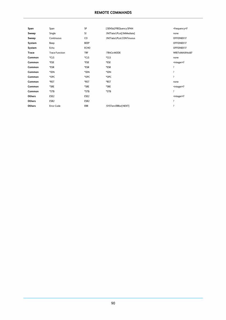
REMOTE COMMANDS
90
Span Span SP [:SENSe]:FREQuency:SPAN <frequency>|?
Sweep Single SI :INITiate:LPLot[:IMMediate] none
Sweep Continuous CO :INITiate:LPLot:CONTinuous OFF|ON|0|1|?
System Beep BEEP OFF|ON|0|1|?
System Echo ECHO OFF|ON|0|1|?
Trace Trace Function TRF :TRACe:MODE WRITe|MAXHold|?
Common *CLS *CLS *CLS none
Common *ESE *ESE *ESE <integer>|?
Common *ESR *ESR *ESR ?
Common *IDN *IDN *IDN ?
Common *OPC *OPC *OPC ?
Common *RST *RST *RST none
Common *SRE *SRE *SRE <integer>|?
Common *STB *STB *STB ?
Others ESE2 ESE2 <integer>|?
Others ESR2 ESR2 ?
Others Error Code ERR :SYSTem:ERRor[:NEXT] ?

REMOTE COMMANDS
91
< SA command order > Index Description SA
Command SCPI Command Suffix
Common *CLS *CLS *CLS none
Common *ESE *ESE *ESE <integer>|?
Common *ESR *ESR *ESR ?
Common *IDN *IDN *IDN ?
Common *OPC *OPC *OPC ?
Common *RST *RST *RST none
Common *SRE *SRE *SRE <integer>|?
Common *STB *STB *STB ?
Amplitude Attenuation AT [:SENSe]:POWer[:RF]:ATTenuation <amplitude>|?
Average Average AVG [:SENSe]:AVERage[:STATe] OFF|ON|0|1|?
Average Average Count AVGC [:SENSe]:AVERage:COUNt <integer>|?
System Beep BEEP OFF|ON|0|1|?
Measurement Pwr vs Time (CCDF) Output
CCDFOUT :FETCh|MEASure|READ:PVTime:CCDF ?
Frequency Center Frequency CF [:SENSe]:FREQuency:CENTer <frequency>|?
Sweep Continuous CO :INITiate:LPLot:CONTinuous OFF|ON|0|1|?
System Echo ECHO OFF|ON|0|1|?
Others Error Code ERR :SYSTem:ERRor[:NEXT] ?
Others ESE2 ESE2 <integer>|?
Others ESR2 ESR2 ?
Measurement EVM (Constellation) OUTPUT
EVMCOUT :FETCh|MEASure|READ:EVM:CONSTellation ?
Measurement EVM (EVM vs Symbol/Sub-Carrier) OUTPUT
EVMOUT :FETCh|MEASure|READ:EVM ?
Measurement EVM (I/Q Wave vs Time) OUTPUT
EVMWOUT :FETCh|MEASure|READ:EVM:WVTime ?
File Copy FCOPY :MMEMory:COPY <`file_name1'>,<`file_name2'>
File Delete FDEL :MMEMory:DELete <`file_name'>
Measurement Spectral Flatness FLATOUT :FETCh|MEASure|READ:FLATness ?
File Load FLOAD :MMEMory:LOAD <`file_name'>
File Move FMOVE :MMEMory:DATA <`file_name'>,definite_length_ block|? <'file_name>
File Read FREAD :MMEMory:CATalog ? <`directory_name'>
File Rename FRENAME :MMEMory:MOVE <`file_name1'>,<`file_name2'>
File Save FSAVE :MMEMory:STORe <`file_name'>
Display Graticule GRAT :DISPlay:WINDow:TRACe:GRATicule:GRID[:STATe] OFF|ON|0|1|?
Printer Hard Copy HCOPY :HCOPy[:IMMediate] none
Marker Marker Amplitude
MA[1~9] :CALCulate:MARKer[1~9]:Y ?
Marker Marker All Off MAO :CALCulate:LPLot:MARKer:AOFF none
Measurement Meas. Start MEA :MEASure:STARt FFT|PVT|PVTC|CCDF|SPEC| EVMC|EVMW|EVM|?
Meas. Control Capturing Time MEAT :MEASure:TIME <time>|?
Marker Marker Freq MF[1~9] :CALCulate:MARKer[1~9]:X <frequency>|?
Marker Marker Mode MM[1~9] :CALCulate:MARKer[1~9]:MODE POSition|DELTa|OFF|?
Mode Mode MODE :INSTrument[:SELect] SA|BASIC|WIMAX|?
Peak Search Peak Search MPK[1~9] :CALCulate:MARKer[1~9]:MAXimum none
Peak Search Next Peak Search MPKN[1~9] :CALCulate:MARKer[1~9]:MAXimum:NEXT none
Marker Marker State MS[1~9] :CALCulate:MARKer[1~9]:STATe OFF|ON|0|1|?
Preset Preset PRST :SYSTem:PRESet none

REMOTE COMMANDS
92
Measurement Pwr vs Time (Crest Factor) Output
PVTCOUT :FETCh|MEASure|READ:PVTime:CREST ?
Measurement Power vs Time Output
PVTOUT :FETCh|MEASure|READ:PVTime ?
Bandwidth Resolution Bandwidth
RB [:SENSe]:BANDwidth|BWIDth[:RESolution] <frequency>|?
Bandwidth Resolution Bandwidth Auto
RBA [:SENSe]:BANDwidth|BWIDth[:RESolution]:AUTO OFF|ON|0|1|?
Frequency Reference REF :INPut:REFerence INTernal|EXTernal|?
Amplitude Ref. Level RL :DISPlay:WINDow:TRACe:Y[:SCALe]:RLEVel <amplitude>|?
Amplitude Scale/Div SD :DISPlay:WINDow:TRACe:Y[:SCALe]:PDIVision <amplitude>|?
Sweep Single SI :INITiate:LPLot[:IMMediate] none
Trace Trace Function TRF :TRACe:MODE WRITe|MAXHold|?
Display White Mode WH :DISPlay:WINDow:WHITe OFF|ON|0|1|?
Mode Setup WiMAX Standard WIMAXSTD 802.16e10MHZ| 802.16e8.75MHZ| 802.16e7MHZ |802.16e5MHZ|?

REMOTE COMMANDS
93
< SCPI command order > Index Description SA
Command SCPI Command Suffix
Common *CLS *CLS *CLS none
Common *ESE *ESE *ESE <integer>|?
Common *ESR *ESR *ESR ?
Common *IDN *IDN *IDN ?
Common *OPC *OPC *OPC ?
Common *RST *RST *RST none
Common *SRE *SRE *SRE <integer>|?
Common *STB *STB *STB ?
Marker Marker All Off MAO :CALCulate:LPLot:MARKer:AOFF none
Peak Search Peak Search MPK[1~9] :CALCulate:MARKer[1~9]:MAXimum none
Peak Search Next Peak Search
MPKN[1~9] :CALCulate:MARKer[1~9]:MAXimum:NEXT none
Marker Marker Mode MM[1~9] :CALCulate:MARKer[1~9]:MODE POSition|DELTa|OFF|?
Marker Marker State MS[1~9] :CALCulate:MARKer[1~9]:STATe OFF|ON|0|1|?
Marker Marker Freq MF[1~9] :CALCulate:MARKer[1~9]:X <frequency>|?
Marker Marker Amplitude
MA[1~9] :CALCulate:MARKer[1~9]:Y ?
Display Graticule GRAT :DISPlay:WINDow:TRACe:GRATicule:GRID[:STATe] OFF|ON|0|1|?
Amplitude Scale/Div SD :DISPlay:WINDow:TRACe:Y[:SCALe]:PDIVision <amplitude>|?
Amplitude Ref. Level RL :DISPlay:WINDow:TRACe:Y[:SCALe]:RLEVel <amplitude>|?
Display White Mode WH :DISPlay:WINDow:WHITe OFF|ON|0|1|?
Measurement EVM (EVM vs Symbol/SubCarrier) OUTPUT
EVMOUT :FETCh|MEASure|READ:EVM ?
Measurement EVM (Constellation) OUTPUT
EVMCOUT :FETCh|MEASure|READ:EVM:CONSTellation ?
Measurement EVM (I/Q Wave vs Time) OUTPUT
EVMWOUT :FETCh|MEASure|READ:EVM:WVTime ?
Measurement Spectral Flatness
FLATOUT :FETCh|MEASure|READ:FLATness ?
Measurement Power vs Time Output
PVTOUT :FETCh|MEASure|READ:PVTime ?
Measurement Pwr vs Time (CCDF) Output
CCDFOUT :FETCh|MEASure|READ:PVTime:CCDF ?
Measurement Pwr vs Time (Crest Factor) Output
PVTCOUT :FETCh|MEASure|READ:PVTime:CREST ?
Printer Hard Copy HCOPY :HCOPy[:IMMediate] none
Sweep Continuous CO :INITiate:LPLot:CONTinuous OFF|ON|0|1|?
Sweep Single SI :INITiate:LPLot[:IMMediate] none
Frequency Reference REF :INPut:REFerence INTernal|EXTernal|?
Mode Mode MODE :INSTrument[:SELect] SA|BASIC|WIMAX|?
Measurement Meas. Start MEA :MEASure:STARt FFT|PVT|FVT|POLAR|WVT| BPSK|QPSK|OQPSK|8~64PSK |4~256QAM|CCDF|?
Meas. Control Capturing Time MEAT :MEASure:TIME <time>|?
File Read FREAD :MMEMory:CATalog ? <`directory_name'>
File Copy FCOPY :MMEMory:COPY <`file_name1'>,<`file_name2'>
File Move FMOVE :MMEMory:DATA <`file_name'>,definite_length_ block|? <'file_name>
File Delete FDEL :MMEMory:DELete <`file_name'>
File Load FLOAD :MMEMory:LOAD <`file_name'>
File Rename FRENAME :MMEMory:MOVE <`file_name1'>,<`file_name2'>
File Save FSAVE :MMEMory:STORe <`file_name'>
Others Error Code ERR :SYSTem:ERRor[:NEXT] ?

REMOTE COMMANDS
94
Preset Preset PRST :SYSTem:PRESet none
Trace Trace Function TRF :TRACe:MODE WRITe|MAXHold|?
Average Average Count AVGC [:SENSe]:AVERage:COUNt <integer>|?
Average Average AVG [:SENSe]:AVERage[:STATe] OFF|ON|0|1|?
Bandwidth Resolution Bandwidth
RB [:SENSe]:BANDwidth|BWIDth[:RESolution] <frequency>|?
Bandwidth Resolution Bandwidth Auto
RBA [:SENSe]:BANDwidth|BWIDth[:RESolution]:AUTO OFF|ON|0|1|?
Frequency Center Frequency
CF [:SENSe]:FREQuency:CENTer <frequency>|?
Frequency Sampling Rate SR [:SENSe]:FREQuency:SAMPling:RATE <frequency>|?
Span Span SP [:SENSe]:FREQuency:SPAN <frequency>|?
Amplitude Attenuation AT [:SENSe]:POWer[:RF]:ATTenuation <amplitude>|?

95
Error codes
Code Description
990
991
992
993
994
995
996
997
998
999
Not supported in current mode
Not installed (option)
System is busy
Execution error (EXE)
Query error (QYE)
Suffix error
Input data size over error
Undefined command
Unnecessary suffix insertion
Undefined suffix

For further information please contact:
Cobham [email protected]/wireless
www.cobham.com/wireless
© Aeroflex Limited