Spectral-Shape Optimized FM Noise Radar for Pulse...
6
Spectral-Shape Optimized FM Noise Radar for Pulse Agility John Jakabosky 1,2 , Shannon D. Blunt 1 , and Braham Himed 3 1 University of Kansas – Radar Systems Lab, Lawrence, KS, USA 2 Naval Research Laboratory – Radar Division, Washington, DC, USA 3 Sensors Directorate, Air Force Research Laboratory, Wright-Patterson AFB, OH Abstract – A non-repeating, spectrum-optimized FM waveform suitable for radar pulse agility is described. The waveform is an alternative manifestation of the recently developed pseudo- random optimized (PRO) FMCW framework for FM noise radar, now implemented in a pulsed form. Each pulsed FM waveform is iteratively optimized to match a spectrum shape with low range sidelobes and good spectral properties, while the random initialization for each waveform ensures sufficient diversity that the resulting optimized form is unique, thereby providing decoherence of range sidelobes. The performance of this pulse-agile structure is examined in simulation and subsequently demonstrated with measured results of static and moving targets. I. INTRODUCTION Noise radar has existed for some time and comprises numerous interesting contributions (e.g. [1-5] to name just a few). The moniker of noise radar generally implies random variation of amplitude and phase according to a complex Gaussian distribution to appear like noise. As such, these waveforms are generally continuous-wave (CW) and are constrained to lower power applications. The notion of frequency modulated (FM) noise radar has been examined theoretically [6,7], and a particular form based on segment- wise spectral shaping optimization was recently demonstrated experimentally [8]. FM noise radar has the notable property of maintaining constant amplitude, thus making it appropriate for high-power radar applications. Here, this latter formulation of FM noise radar is modified to facilitate realization of a non- repeating form of pulse agility, thus extending the applicability to include both CW (from [8]) and pulsed operation. II. SPECTRALLY SHAPED OPTIMIZATION The spectral-shaping waveform optimization used here has been experimentally demonstrated to facilitate non-repeating FMCW waveforms (denoted pseudo-random optimized or PRO-FMCW) [8] and enable joint optimization of an FM waveform and amplitude taper to achieve ultra-low range sidelobes [9]. This approach has also been shown in simulation and experimentally to provide the means to incorporate both stationary and time-hopped spectral gaps [10,11] for in-band interference avoidance and may potentially enable a form of tandem-hopped radar/communications. It has likewise been applied to design wideband physical MIMO radar waveforms that minimize reactive power [12], which could otherwise damage the transmitter [13,14]. The extension of PRO-FMCW from [8] to a pulse-agile instantiation of FM noise radar (which we denote PRO-FM) is actually rather straightforward. The waveform in [8] was constructed (i.e. initialized and optimized) on a segment-wise basis, with each new segment phase-rotated to adjoin the previous segment in a manner that avoided phase discontinuities. Here, these segments simply become the individual pulsed waveforms. This optimization scheme relies on alternating projections (e.g. [15-17]) in terms of the spectral and temporal envelopes. The spectral shape, specifically the power spectral density (PSD) 2 ( ) Gf , provides the means to the optimize the FM waveform due to the Fourier relationship between PSD and waveform autocorrelation, and the fact that low range sidelobes are achieved when the spectrum tapers towards the band edges [18,19]. As such, the Gaussian PSD is particularly useful since the Fourier transform of a Gaussian is another Gaussian (and thus would theoretically possess no sidelobes). For high-power operation, where the power amplifier (PA) is operated in saturation (noting that for many tube-based PAs “on” or “off” are essentially the only options), the time domain envelope () ut is set to a constant value over pulsewidth T. Given the desired PSD and time-domain envelope, the design of the mth pulsed waveform is first initialized with a random waveform, denoted 0, ( ), m p t to ensure diversity among the set of optimized waveforms. The optimization is then performed by the alternating application of { } ( ) { } 1 1, , () ( ) exp () k m km r t Gf j p t − + = ∠ F F (1) and ( ) 1, 1, () ( )exp () k m k m p t ut j r t + + = ∠ , (2) where () ut has time support on [0, T], F and 1 − F are the Fourier and inverse Fourier transforms, and () ∠• extracts the phase of the argument. After K iterations, the mth PRO-FM pulsed waveform , () Km p t is obtained. Note that to perform (1) and (2) necessitates using discretized versions of |G( f )|, u(t), r k,m (t), and p k,m (t) that should be “over-sampled” with respect to the 3-dB bandwidth of the PSD to ensure sufficient fidelity. Further, the optimization process can be efficiently implemented using FFTs. Once emitted, the echoes generated from these pulse- agile waveforms can be receive processed using standard pulse compression, Doppler processing, and clutter cancellation. The following examines the simulated sidelobe performance for This work was supported by a subcontract with Matrix Research, Inc. for research sponsored by AFRL under Prime Contract # FA8650-14-D-1722.
Transcript of Spectral-Shape Optimized FM Noise Radar for Pulse...

Spectral-Shape Optimized FM Noise Radar
for Pulse Agility
John Jakabosky1,2
, Shannon D. Blunt1, and Braham Himed
3
1University of Kansas – Radar Systems Lab, Lawrence, KS, USA
2Naval Research Laboratory – Radar Division, Washington, DC, USA
3Sensors Directorate, Air Force Research Laboratory, Wright-Patterson AFB, OH
Abstract – A non-repeating, spectrum-optimized FM waveform
suitable for radar pulse agility is described. The waveform is an
alternative manifestation of the recently developed pseudo-
random optimized (PRO) FMCW framework for FM noise
radar, now implemented in a pulsed form. Each pulsed FM
waveform is iteratively optimized to match a spectrum shape
with low range sidelobes and good spectral properties, while the
random initialization for each waveform ensures sufficient
diversity that the resulting optimized form is unique, thereby
providing decoherence of range sidelobes. The performance of
this pulse-agile structure is examined in simulation and
subsequently demonstrated with measured results of static and
moving targets.
I. INTRODUCTION
Noise radar has existed for some time and comprises numerous interesting contributions (e.g. [1-5] to name just a few). The moniker of noise radar generally implies random variation of amplitude and phase according to a complex Gaussian distribution to appear like noise. As such, these waveforms are generally continuous-wave (CW) and are constrained to lower power applications. The notion of frequency modulated (FM) noise radar has been examined theoretically [6,7], and a particular form based on segment-wise spectral shaping optimization was recently demonstrated experimentally [8]. FM noise radar has the notable property of maintaining constant amplitude, thus making it appropriate for high-power radar applications. Here, this latter formulation of FM noise radar is modified to facilitate realization of a non-repeating form of pulse agility, thus extending the applicability to include both CW (from [8]) and pulsed operation.
II. SPECTRALLY SHAPED OPTIMIZATION
The spectral-shaping waveform optimization used here has been experimentally demonstrated to facilitate non-repeating FMCW waveforms (denoted pseudo-random optimized or PRO-FMCW) [8] and enable joint optimization of an FM waveform and amplitude taper to achieve ultra-low range sidelobes [9]. This approach has also been shown in simulation and experimentally to provide the means to incorporate both stationary and time-hopped spectral gaps [10,11] for in-band interference avoidance and may potentially enable a form of tandem-hopped radar/communications. It has likewise been applied to design wideband physical MIMO radar waveforms that minimize reactive power [12], which could otherwise damage the transmitter [13,14].
The extension of PRO-FMCW from [8] to a pulse-agile instantiation of FM noise radar (which we denote PRO-FM) is
actually rather straightforward. The waveform in [8] was constructed (i.e. initialized and optimized) on a segment-wise basis, with each new segment phase-rotated to adjoin the previous segment in a manner that avoided phase discontinuities. Here, these segments simply become the individual pulsed waveforms.
This optimization scheme relies on alternating projections (e.g. [15-17]) in terms of the spectral and temporal envelopes. The spectral shape, specifically the power spectral density
(PSD) 2
( )G f , provides the means to the optimize the FM
waveform due to the Fourier relationship between PSD and waveform autocorrelation, and the fact that low range sidelobes are achieved when the spectrum tapers towards the band edges [18,19]. As such, the Gaussian PSD is particularly useful since the Fourier transform of a Gaussian is another Gaussian (and thus would theoretically possess no sidelobes). For high-power operation, where the power amplifier (PA) is operated in saturation (noting that for many tube-based PAs “on” or “off” are essentially the only options), the time domain envelope
( )u t is set to a constant value over pulsewidth T.
Given the desired PSD and time-domain envelope, the design of the mth pulsed waveform is first initialized with a
random waveform, denoted 0, ( ),mp t to ensure diversity among
the set of optimized waveforms. The optimization is then performed by the alternating application of
{ }( ){ }11, ,( ) ( ) exp ( )k m k mr t G f j p t
−+ = ∠F F (1)
and
( )1, 1,( ) ( ) exp ( )k m k mp t u t j r t+ += ∠ , (2)
where ( )u t has time support on [0, T], F and 1−F are the
Fourier and inverse Fourier transforms, and ( )∠ • extracts the
phase of the argument. After K iterations, the mth PRO-FM
pulsed waveform , ( )K mp t is obtained.
Note that to perform (1) and (2) necessitates using discretized versions of |G( f )|, u(t), rk,m(t), and pk,m(t) that should be “over-sampled” with respect to the 3-dB bandwidth of the PSD to ensure sufficient fidelity. Further, the optimization process can be efficiently implemented using FFTs. Once emitted, the echoes generated from these pulse-agile waveforms can be receive processed using standard pulse compression, Doppler processing, and clutter cancellation. The following examines the simulated sidelobe performance for
This work was supported by a subcontract with Matrix Research, Inc. for research sponsored by AFRL under Prime Contract # FA8650-14-D-1722.
this pulsed form of FM noise radar followed by demonstration using experimental measurements.
III. SIMULATION RESULTS
A set of M = 104 PRO-FM waveforms were designed to
demonstrate their performance for pulse agility. Each waveform has a temporal extent of T = 1.6 µs and a pre-optimization 3-dB bandwidth of 80 MHz. Each waveform optimization was initialized by a random FM waveform generated by a random sampling of 128 phase values drawn
from a uniform distribution on [−π, π] and implemented with the polyphase-coded FM (PCFM) framework [20]. Each waveform was optimized for K = 500 iterations.
The chosen PSD has a Gaussian shape with 3dB bandwidth of 55 MHz, such that the resulting time-bandwidth product of each PRO-FM waveform is 88. While the associated Gaussian autocorrelation should theoretically possess no sidelobes, the practical sidelobe level is determined by the bit error floor of the discretized signal after conversion to analog.
For the results shown, all 104 waveforms are included in a
single coherent processing interval (CPI). From a practical standpoint, such a large number of pulses would require either a very long CPI or a high PRF. However, due to their non-repeating nature these waveforms naturally address range-ambiguous clutter and targets, thus supporting the use of a higher PRF. The main disadvantage would be the large blind ranges produced by the high duty cycle required. As such, the impact of a lower PRF (with much fewer pulses) is also examined in the subsequent section.
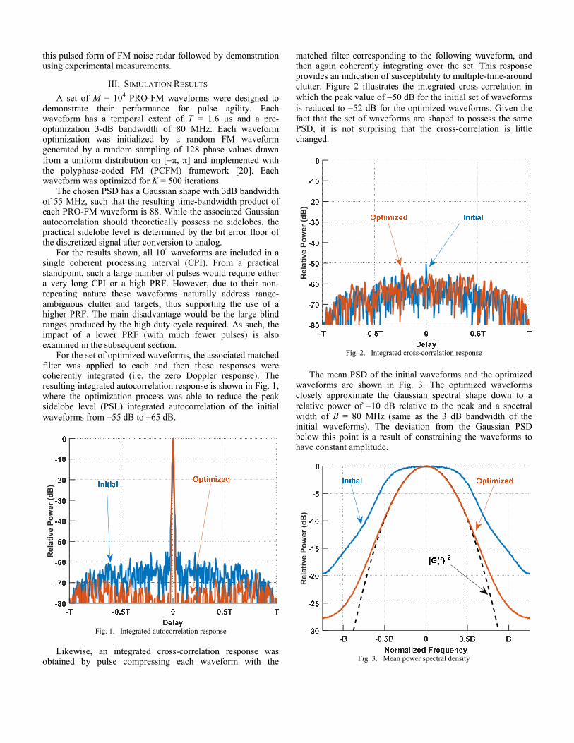
For the set of optimized waveforms, the associated matched filter was applied to each and then these responses were coherently integrated (i.e. the zero Doppler response). The resulting integrated autocorrelation response is shown in Fig. 1, where the optimization process was able to reduce the peak sidelobe level (PSL) integrated autocorrelation of the initial
waveforms from −55 dB to −65 dB.
Rela
tive P
ow
er
(dB
)
Fig. 1. Integrated autocorrelation response
Likewise, an integrated cross-correlation response was
obtained by pulse compressing each waveform with the
matched filter corresponding to the following waveform, and then again coherently integrating over the set. This response provides an indication of susceptibility to multiple-time-around clutter. Figure 2 illustrates the integrated cross-correlation in
which the peak value of −50 dB for the initial set of waveforms
is reduced to −52 dB for the optimized waveforms. Given the fact that the set of waveforms are shaped to possess the same PSD, it is not surprising that the cross-correlation is little changed.
Rela
tive P
ow
er
(dB
)
Fig. 2. Integrated cross-correlation response
The mean PSD of the initial waveforms and the optimized waveforms are shown in Fig. 3. The optimized waveforms closely approximate the Gaussian spectral shape down to a
relative power of −10 dB relative to the peak and a spectral width of B = 80 MHz (same as the 3 dB bandwidth of the initial waveforms). The deviation from the Gaussian PSD below this point is a result of constraining the waveforms to have constant amplitude.
Rela
tive P
ow
er
(dB
)
Fig. 3. Mean power spectral density
IV. EXPERIMENTALLY MEASURED RESULTS
To demonstrate the use of these optimized FM noise radar waveforms for pulse agility, their free-space performance was measured using a radar testbed in two separate tests. The first test was used to demonstrate dynamic range against static scatterers, with the second aimed at demonstrating detection capabilities against moving targets. For both tests, the waveforms were upsampled to a sampling rate of 6.25 GS/s and upconverted to a center frequency of 2.3 GHz. A pulse repetition interval (PRI) of 10 µs was selected, yielding a duty cycle of 16% and a PRF of 100 kHz, which allows for an unambiguous range of 1.5 km. Each waveform was loaded onto a Tektronix AWG70002 waveform generator at a 10 bit resolution. A wideband test amplifier with 27 dB gain was used for additional amplification of the transmit signal. A Rohde & Schwarz FSW spectrum analyzer was used to capture complex baseband samples of the received signal at 200 MS/s.
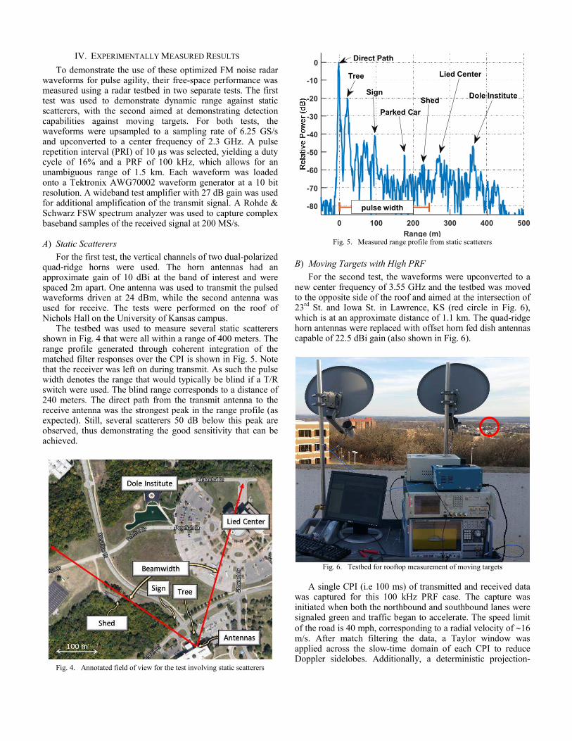
A) Static Scatterers
For the first test, the vertical channels of two dual-polarized quad-ridge horns were used. The horn antennas had an approximate gain of 10 dBi at the band of interest and were spaced 2m apart. One antenna was used to transmit the pulsed waveforms driven at 24 dBm, while the second antenna was used for receive. The tests were performed on the roof of Nichols Hall on the University of Kansas campus.
The testbed was used to measure several static scatterers shown in Fig. 4 that were all within a range of 400 meters. The range profile generated through coherent integration of the matched filter responses over the CPI is shown in Fig. 5. Note that the receiver was left on during transmit. As such the pulse width denotes the range that would typically be blind if a T/R switch were used. The blind range corresponds to a distance of 240 meters. The direct path from the transmit antenna to the receive antenna was the strongest peak in the range profile (as expected). Still, several scatterers 50 dB below this peak are observed, thus demonstrating the good sensitivity that can be achieved.
Fig. 4. Annotated field of view for the test involving static scatterers
0 100 200 300 400 500
Range (m)
-80
-70
-60
-50
-40
-30
-20
-10
0
Lied CenterTree
Direct Path
ShedDole InstituteSign
Parked Car
pulse width
Fig. 5. Measured range profile from static scatterers
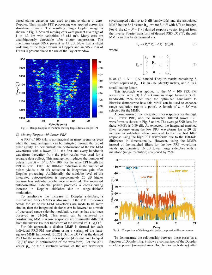
B) Moving Targets with High PRF
For the second test, the waveforms were upconverted to a new center frequency of 3.55 GHz and the testbed was moved to the opposite side of the roof and aimed at the intersection of 23
rd St. and Iowa St. in Lawrence, KS (red circle in Fig. 6),
which is at an approximate distance of 1.1 km. The quad-ridge horn antennas were replaced with offset horn fed dish antennas capable of 22.5 dBi gain (also shown in Fig. 6).
Fig. 6. Testbed for rooftop measurement of moving targets
A single CPI (i.e 100 ms) of transmitted and received data
was captured for this 100 kHz PRF case. The capture was initiated when both the northbound and southbound lanes were signaled green and traffic began to accelerate. The speed limit
of the road is 40 mph, corresponding to a radial velocity of ∼16 m/s. After match filtering the data, a Taylor window was applied across the slow-time domain of each CPI to reduce Doppler sidelobes. Additionally, a deterministic projection-
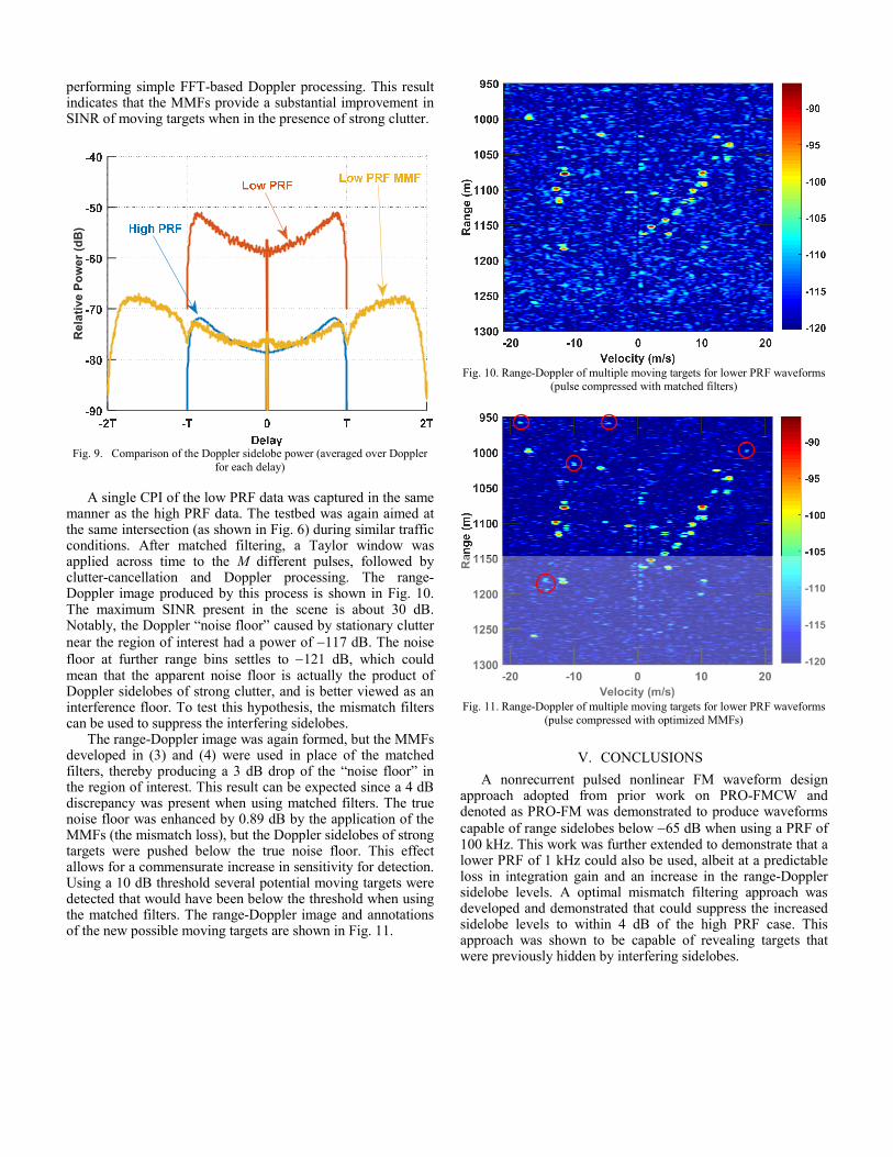
based clutter canceller was used to remove clutter at zero-Doppler. Then simple FFT processing was applied across the slow-time domain. The resulting range-Doppler image is shown in Fig. 7. Several moving cars were present at a range of 1 to 1.3 km with velocities of ±18 m/s. Many cars are unambiguously detectable after clutter suppression. The maximum target SINR present is 45 dB. Note that a slight widening of the target returns in Doppler and an SINR loss of 1.5 dB is present due to the use of the Taylor window.
Fig. 7. Range-Doppler of multiple moving targets from a single CPI
C) Moving Targets with Lower PRF
A PRF of 100 kHz is not practical in many scenarios even when the range ambiguity can be mitigated through the use of pulse agility. To demonstrate the performance of the PRO-FM waveforms with a lower PRF, the first and every hundredth waveform thereafter from the prior results was used for a separate data collect. This arrangement reduces the number of pulses from M = 10
4 to M = 100. For the same CPI length the
PRF is now 1 kHz. The 100-fold reduction in the number of pulses yields a 20 dB reduction in integration gain after Doppler processing. Additionally, the sidelobe level of the integrated autocorrelation is approximately 20 dB higher because less sidelobe decoherence is realized. The increased autocorrelation sidelobe power produces a corresponding increase in Doppler sidelobes due to range-sidelobe modulation.
To ameliorate the increase in Doppler sidelobes, a mismatched filter (MMF) is also used. If the MMF responses across the set of PRO-FM waveforms are made to be more similar, then the integrated sidelobes can be lowered as a result of decreased range-sidelobe modulation, such as has also been observed in [21-24]. This result can be achieved by constructing MMFs whose responses are minimally different from the inverse Fourier transform of the desired PSD |G( f )|
2.
For this approach, a distinct MMF is formed for each individual PRO-FM waveform using a variant of the least-squares MMF framework [20,25]. Define |D( f )|
2 as the desired
PSD for the mismatched filter response (does not have to equal |G( f )|
2 used in optimization of the waveform). Let the N×1
vector mp be the discretized version of the mth waveform
(oversampled relative to 3 dB bandwidth) and the associated
MMF be the L×1 vector mh , where L > N with L/N an integer.
For d the (L + N – 1)×1 desired response vector formed from
the inverse Fourier transform of desired PSD |D( f )|2, the mth
MMF can thus be determined via
1( ) ( )Hm m m mδ −= +h P P I P d , (3)
where
0 0
0 0
0 0
m
m
m
m
=
p
pP
p
⋯
…
⋮ ⋮ ⋱ ⋮
…
(4)
is an (L + N – 1)×L banded Toeplitz matrix containing L
shifted copies of mp , I is an L×L identity matrix, and δ is a
small loading factor. This approach was applied to the M = 100 PRO-FM
waveforms, with |D( f )|2 a Gaussian shape having a 3 dB
bandwidth 25% wider than the optimized bandwidth to likewise demonstrate how this MMF can be used to enhance range resolution (up to a point). A length of L = 3N was selected for the MMF.
A comparison of the integrated filter responses for the high PRF, lower PRF, and the mismatch filtered lower PRF waveforms is shown in Fig. 8 and 9. The average SNR loss for these MMFs is 0.89 dB. As expected, the integrated matched filter response using the low PRF waveforms has a 20 dB increase in sidelobes when compared to the matched filter response using the high PRF waveforms due to the 100-fold difference in dimensionality. However, using the MMFs instead of the matched filters for the low PRF waveforms yields approximately 16 dB lower range sidelobes with a mainlobe (range resolution) sharpened by 25%.
Re
lati
ve
Po
we
r (d
B)
Fig. 8. Comparison of the integrated pulse compression filter responses
To demonstrate the relationship between these cases as a
function of Doppler, Fig. 9 shows a comparison of the Doppler sidelobe power (averaged over Doppler for each delay) after
performing simple FFT-based Doppler processing. This result indicates that the MMFs provide a substantial improvement in SINR of moving targets when in the presence of strong clutter.
Re
lati
ve
Po
we
r (d
B)
Fig. 9. Comparison of the Doppler sidelobe power (averaged over Doppler
for each delay)
A single CPI of the low PRF data was captured in the same
manner as the high PRF data. The testbed was again aimed at the same intersection (as shown in Fig. 6) during similar traffic conditions. After matched filtering, a Taylor window was applied across time to the M different pulses, followed by clutter-cancellation and Doppler processing. The range-Doppler image produced by this process is shown in Fig. 10. The maximum SINR present in the scene is about 30 dB. Notably, the Doppler “noise floor” caused by stationary clutter
near the region of interest had a power of −117 dB. The noise
floor at further range bins settles to −121 dB, which could mean that the apparent noise floor is actually the product of Doppler sidelobes of strong clutter, and is better viewed as an interference floor. To test this hypothesis, the mismatch filters can be used to suppress the interfering sidelobes.
The range-Doppler image was again formed, but the MMFs developed in (3) and (4) were used in place of the matched filters, thereby producing a 3 dB drop of the “noise floor” in the region of interest. This result can be expected since a 4 dB discrepancy was present when using matched filters. The true noise floor was enhanced by 0.89 dB by the application of the MMFs (the mismatch loss), but the Doppler sidelobes of strong targets were pushed below the true noise floor. This effect allows for a commensurate increase in sensitivity for detection. Using a 10 dB threshold several potential moving targets were detected that would have been below the threshold when using the matched filters. The range-Doppler image and annotations of the new possible moving targets are shown in Fig. 11.
Fig. 10. Range-Doppler of multiple moving targets for lower PRF waveforms
(pulse compressed with matched filters)
Fig. 11. Range-Doppler of multiple moving targets for lower PRF waveforms
(pulse compressed with optimized MMFs)
V. CONCLUSIONS
A nonrecurrent pulsed nonlinear FM waveform design approach adopted from prior work on PRO-FMCW and denoted as PRO-FM was demonstrated to produce waveforms
capable of range sidelobes below −65 dB when using a PRF of 100 kHz. This work was further extended to demonstrate that a lower PRF of 1 kHz could also be used, albeit at a predictable loss in integration gain and an increase in the range-Doppler sidelobe levels. A optimal mismatch filtering approach was developed and demonstrated that could suppress the increased sidelobe levels to within 4 dB of the high PRF case. This approach was shown to be capable of revealing targets that were previously hidden by interfering sidelobes.
REFERENCES
[1] X. Xiaojian, R.M. Narayanan, “Range sidelobe suppression technique for coherent ultra wide-band random noise radar imaging,” IEEE Trans. Antennas & Propagation, vol. 49, no. 12, pp. 1836-1842, Dec. 2001.
[2] L. Zhixi, R.M. Narayanan, “Doppler visibility of coherent ultrawideband random noise radar systems,” IEEE Trans. Aerospace & Electronic Systems, vol. 42, no. 3, pp. 904-916, July 2006.
[3] D. Tarchi, K. Lukin, J. Fortuny-Guasch, A. Mogyla, P. Vyplavin, A. Sieber, “SAR imaging with noise radar,” IEEE Trans. Aerospace & Electronic Systems, vol. 46, no. 3, pp. 1214-1225, July 2010.
[4] T. Thayaparan, M. Dakovic, L. Stankovic, “Mutual interference and low probability of interception capabilities of noise radar,” IET Radar, Sonar & Navigation, vol. 2, no. 4, pp. 294-305, 2008.
[5] M. Malanowski, K. Kulpa, “Detection of moving targets with continuous-wave noise radar: theory and measurements,” IEEE Trans. Geoscience & Remote Sensing, vol. 50, no. 9, pp. 3502-3509, Sept. 2012.
[6] S.R.J. Axelsson, “Noise radar using random phase and frequency modulation,” IEEE Trans. Geoscience & Remote Sensing, vol. 42, no. 11, pp. 2370-2384, Nov. 2004.
[7] L. Pralon, B. Pompeo, J.M. Fortes, “Stochastic analysis of random frequency modulated waveforms for noise radar systems,” IEEE Trans. Aerospace & Electronic Systems, vol. 51, no. 2, pp. 1447-1461, Apr. 2015.
[8] J. Jakabosky, S.D. Blunt, B. Himed, “Waveform design and receive processing for nonrecurrent nonlinear FMCW radar” IEEE Intl. Radar Conf., Washington, DC, May 2015.
[9] J. Jakabosky, S.D. Blunt, T. Higgins, “Ultra-low sidelobe waveform design via spectral shaping and LINC transmit architecture” IEEE Intl. Radar Conf., Washington, DC, May 2015.
[10] J. Jakabosky, S.D. Blunt, A. Martone, “Incorporating hopped spectral gaps into nonrecurrent nonlinear FMCW radar emission,” IEEE Intl. Workshop on Computational Advances in Multi-Sensor Adaptive Processing, Cancun, Mexico, Dec. 2015.
[11] J. Jakabosky, B. Ravenscroft, S.D. Blunt, B. Himed, “Gapped spectrum shaping for tandem-hopped radar/communications & cognitive sensing,” IEEE Radar Conf., Philadelphia, PA, May 2016.
[12] P.M. McCormick, S.D. Blunt, J. Metcalf, “Joint spectrum/ beampattern design of wideband FM MIMO radar emissions,” IEEE Radar Conf., Philadelphia, PA, May 2016.
[13] G. Frazer, Y. Abramovich, B. Johnson, “Spatially waveform diverse radar: perspectives for high frequency OTHR,” IEEE Radar Conf., pp. 385–390, Boston, MA, Apr. 2007.
[14] F. Daum, J. Huang, “MIMO radar: snake oil or good idea?” IEEE Aerospace & Electronic Systems Mag., vol. 24, no. 5, pp. 8-12, May 2009.
[15] A. Levi, H. Stark, “Image restoration by the method of generalized projections with application to restoration from magnitude,” J. Opt. Soc. Am., vol. 1, no. 9, pp. 932-943, Sept. 1984.
[16] O.M. Bucci, G. Franceschetti, G. Mazzarella, G. Panariello, “Intersection approach to array pattern synthesis,” IEE Proc. H – Microwaves, Antennas and Propagation, vol. 137, no. 6, pp. 349-357, Dec. 1990.
[17] H.H. Bauschke, J.M. Borwein, “On projection algorithms for solving convex feasibility problems,” SIAM Review, vol. 38, no. 3, pp. 367-426, Sept. 1996.
[18] A. Johnston, “Improvements to a pulse compression radar matched filter,” Radio & Electronic Engineer, vol. 53, no. 4, pp. 138-140, Apr. 1983.
[19] J.A. Johnston, A.C. Fairhead, “Waveform design and Doppler sensitivity analysis for nonlinear FM chirp pulses,” IEE Proc. F –Communications, Radar & Signal Processing, vol. 133, no. 2, pp. 163-175, Apr. 1986.
[20] S.D. Blunt, M. Cook, J. Jakabosky, J. de Graaf, E. Perrins, "Polyphase-coded FM (PCFM) radar waveforms, part I: implementation," IEEE Trans. Aerospace & Electronic Systems, vol. 50, no. 3, pp. 2218-2229, July 2014.
[21] S. Blunt, M. Cook, J. Stiles, “Embedding information into radar emissions via waveform implementation,” Intl. Waveform Diversity & Design Conf., Niagara Falls, Canada, Aug. 2010.
[22] M. Cook, S.D. Blunt, J. Jakabosky, “Optimization of waveform diversity and performance for pulse-agile radar,” IEEE Radar Conf., Kansas City, MO, May 2011.
[23] A. O’Connor, J. Kantor, J. Jakabosky, “Joint equalization filters that mitigate waveform-diversity modulation of clutter,” IEEE Radar Conf., Philadelphia, PA, May 2016.
[24] A. O’Connor, J. Kantor, J. Jakabosky, “Space-time adaptive mismatch processing,” IEEE Radar Conf., Philadelphia, PA, May 2016.
[25] M.H. Ackroyd, F. Ghani, “Optimum mismatched filters for sidelobe suppression,” IEEE Trans. Aerospace & Electronic Systems, vol. AES-9, no. 2, pp. 214-218, Mar. 1973.


![Cloud radar spectral polarimetry for atmospheric research · Case study, 9 June 2018, 21:20 UTC Spectral reflectivity [dBZ] Observations at 30˚ elevation Strong attenuation Slower](https://static.fdocuments.in/doc/165x107/5ec67c8fae6d260984338091/cloud-radar-spectral-polarimetry-for-atmospheric-case-study-9-june-2018-2120.jpg)