Spectra Tape Libraries - Spectra Logic Support Portal · April 2015 SCSI Developer’s...
116
SpectraLogic.com Spectra Tape Libraries SCSI Developer’s Guide
-
Upload
hoangtuong -
Category
Documents
-
view
222 -
download
0
Transcript of Spectra Tape Libraries - Spectra Logic Support Portal · April 2015 SCSI Developer’s...

SpectraLogic.com
Spectra Tape Libraries
SCSI Developer’s Guide

April 2015 SCSI Developer’s Guide—Spectra Tape Libraries2
Copyright Copyright © 2005–2015 Spectra Logic Corporation. All rights reserved. This item and the information contained herein are the property of Spectra Logic Corporation.
Notices Except as expressly stated herein, Spectra Logic Corporation makes its products and associated documentation on an “AS IS” BASIS, WITHOUT WARRANTY OF ANY KIND, EITHER EXPRESSED OR IMPLIED, INCLUDING BUT NOT LIMITED TO THE IMPLIED WARRANTIES OF MERCHANTABILITY OR FITNESS FOR A PARTICULAR PURPOSE, BOTH OF WHICH ARE EXPRESSLY DISCLAIMED. In no event shall Spectra Logic be liable for any loss of profits, loss of business, loss of use or data, interruption of business, or for indirect, special, incidental or consequential damages of any kind, even if Spectra Logic has been advised of the possibility of such damages arising from any defect or error.
Information furnished in this manual is believed to be accurate and reliable. However, no responsibility is assumed by Spectra Logic for its use. Due to continuing research and development, Spectra Logic may revise this publication from time to time without notice, and reserves the right to change any product specification at any time without notice.
Trademarks BlueScale, CC, Spectra, SpectraGuard, Spectra Logic, TeraPack, and TranScale are registered trademarks of Spectra Logic Corporation. ArchiveGrade, BlackPearl, IntraCloud, nTier Verde, and Verde are trademarks of Spectra Logic Corporation. All rights reserved worldwide. All other trademarks and registered trademarks are the property of their respective owners.
Part Number 90940001 Revision G
RevisionHistory
Note: To make sure you have the most current version of this guide check the Spectra Logic website at support.spectralogic.com/documentation. To make sure you have the release notes for the most current version of the BlueScale software, log into the Spectra Logic Technical Support portal at support.spectralogic.com. The release notes contain updates to the User Guide since the last time it was revised.
Revision Date Description
E September 2005
F October 2009 Updated to encompass all tape libraries that return SPECTRA PYTHON in the Inquiry string. Removed unsupported Extended Copy and Receive Copy Results commands.
G April 2015 Update commands for new features. Add READ BUFFER command. Update trademarks.

April 2015 SCSI Developer’s Guide—Spectra Tape Libraries3
End UserLicense
Agreement
You have acquired a Spectra product that includes software owned or licensed by Spectra Logic from one or more software licensors (“Software Suppliers”). Such software products, as well as associated media, printed materials and “online” or electronic documentation (“SOFTWARE”) are protected by copyright laws and international copyright treaties, as well as other intellectual property laws and treaties.
If you do not agree to this end user license agreement (EULA), do not use the Spectra product; instead, promptly contact Spectra Logic for instructions on return of the Spectra product for a refund. Any use of the Software, including but not limited to use on the Spectra product, will constitute your agreement to this EULA (or ratification of any previous consent).
Grant of License. The Software is licensed on a non‐exclusive basis, not sold. This EULA grants you the following rights to the Software:
You may use the Software only on the Spectra product.
Not Fault Tolerant. The Software is not fault tolerant. Spectra Logic has independently determined how to use the Software in the Spectra product, and suppliers have relied upon Spectra Logic to conduct sufficient testing to determine that the Software is suitable for such use.
No Warranties for the SOFTWARE. The Software is provided “AS IS” and with all faults. The entire risk as to satisfactory quality, performance, accuracy, and effort (including lack of negligence) is with you. Also, there is no warranty against interference with your enjoyment of the Software or against infringement. If you have received any warranties regarding the SOFTWARE, those warranties do not originate from, and are not binding on Software suppliers.
Note on Java Support. The Software may contain support for programs written in Java. Java technology is not fault tolerant and is not designed, manufactured, or intended for use of resale as online control equipment in hazardous environments requiring fail‐safe performance, such as in the operation of nuclear facilities, aircraft navigation or communications systems, air traffic control, direct life support machines, or weapons systems, in which the failure of Java technology could lead directly to death, personal injury, or severe physical or environmental damage.
No Liability for Certain Damages. Except as prohibited by law, Software suppliers shall have no liability for any indirect, special, consequential or incidental damages arising from or in connection with the use or performance of the Software. This limitation shall apply even if any remedy fails of its essential purpose. In no event shall Software suppliers, individually, be liable for any amount in excess of U.S. two hundred fifty dollars (U.S. $250.00).
Limitations on Reverse Engineering, Decompilation, and Disassembly. You may not reverse engineer, decompile, or disassemble the Software, except and only to the extent that such activity is expressly permitted by applicable law notwithstanding this limitation.
Software Transfer Allowed with Restrictions. You may permanently transfer rights under this EULA only as part of a permanent sale or transfer of the Spectra product, and only if the recipient agrees to this EULA. If the Software is an upgrade, any transfer must also include all prior versions of the Software.
Export Restrictions. Export of the Software from the United States is regulated by the Export Administration Regulations (EAR, 15 CFR 730‐744) of the U.S. Commerce Department, Bureau of Export Administration. You agree to comply with the EAR in the export or re‐export of the Software: (i) to any country to which the U.S. has embargoed or restricted the export of goods or services, which as May 1999 include, but are not necessarily limited to Cuba, Iran, Iraq, Libya, North Korea, Sudan, Syria, and the Federal Republic of Yugoslavia (including Serbia, but not Montenegro), or to any national or any such country, wherever located, who intends to transit or transport the Software back to such country; (ii) to any person or entity who you know or have reason to know will utilize the Software or portion thereof in the design, development or production of nuclear, chemical, or biological weapons; or (iii) to any person or entity who has been prohibited from participating in U.S. export transactions by any federal agency of the U.S. government. You warrant and represent that neither the BXA nor any other U.S. federal agency has suspended, revoked or denied your export privileges.

April 2015 SCSI Developer’s Guide—Spectra Tape Libraries4
Contacting Spectra Logic
To Obtain General Information
Spectra Logic Website: www.spectralogic.com
United States Headquarters European Office
Spectra Logic Corporation6285 Lookout RoadBoulder, CO 80301USA
Phone: 1.800.833.1132 or 1.303.449.6400International: 1.303.449.6400Fax: 1.303.939.8844
Spectra Logic Europe Ltd.Venture HouseArlington Square, Downshire WayBracknell, RG12 1WAUnited Kingdom
Phone: 44 (0) 870.112.2150
Fax: 44 (0) 870.112.2175
Spectra Logic Technical Support
Technical Support Portal: support.spectralogic.com
United States and CanadaPhone:
Toll free US and Canada: 1.800.227.4637
International: 1.303.449.0160
Europe, Middle East, AfricaPhone: 44 (0) 870.112.2185
Deutsch Sprechende KundenPhone: 49 (0) 6028.9796.507
Email: [email protected]
Mexico, Central and South America, Asia, Australia, and New ZealandPhone: 1.303.449.0160
Spectra Logic Sales
Website: www.spectralogic.com/shop
United States and CanadaPhone: 1.800.833.1132 or 1.303.449.6400
Fax: 1.303.939.8844Email: [email protected]
EuropePhone: 44 (0) 870.112.2150
Fax: 44 (0) 870.112.2175
Email: [email protected]
To Obtain Documentation
Spectra Logic Website: support.spectralogic.com/documentation
5
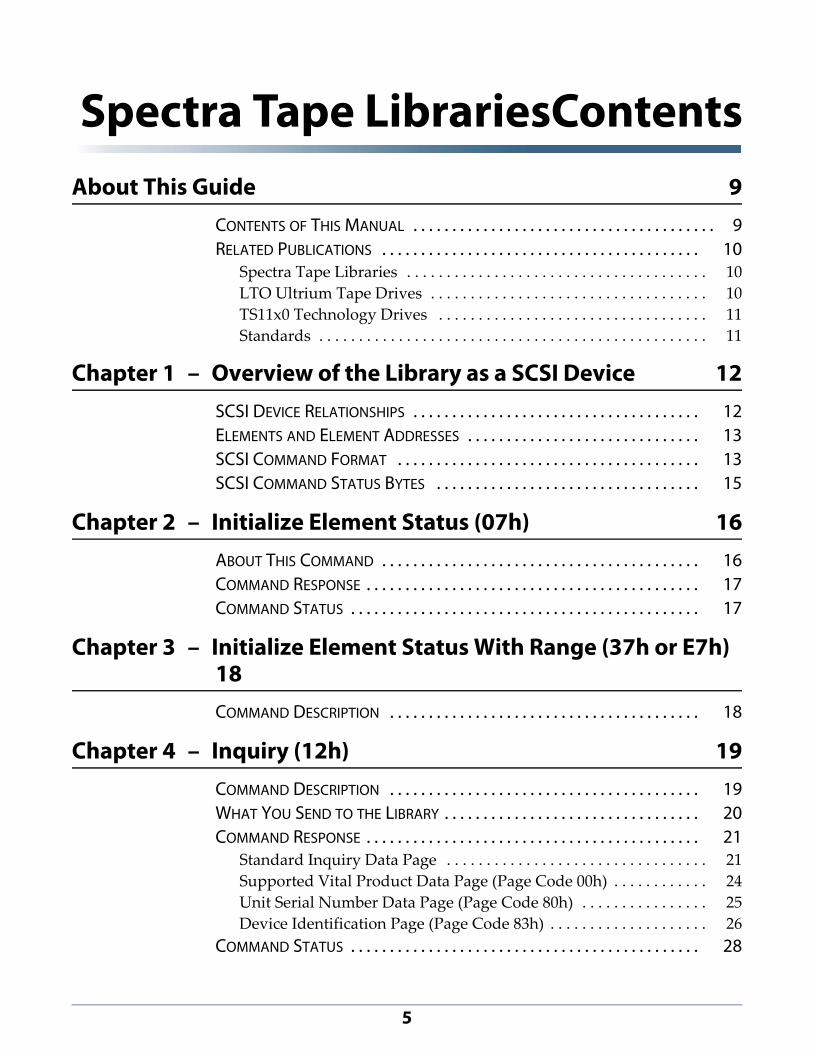
Spectra Tape LibrariesContentsAbout This Guide 9
CONTENTS OF THIS MANUAL . . . . . . . . . . . . . . . . . . . . . . . . . . . . . . . . . . . . . . . 9RELATED PUBLICATIONS . . . . . . . . . . . . . . . . . . . . . . . . . . . . . . . . . . . . . . . . . 10
Spectra Tape Libraries . . . . . . . . . . . . . . . . . . . . . . . . . . . . . . . . . . . . . . 10
LTO Ultrium Tape Drives . . . . . . . . . . . . . . . . . . . . . . . . . . . . . . . . . . . 10
TS11x0 Technology Drives . . . . . . . . . . . . . . . . . . . . . . . . . . . . . . . . . . 11
Standards . . . . . . . . . . . . . . . . . . . . . . . . . . . . . . . . . . . . . . . . . . . . . . . . . 11
Chapter 1 – Overview of the Library as a SCSI Device 12SCSI DEVICE RELATIONSHIPS . . . . . . . . . . . . . . . . . . . . . . . . . . . . . . . . . . . . . 12ELEMENTS AND ELEMENT ADDRESSES . . . . . . . . . . . . . . . . . . . . . . . . . . . . . . 13SCSI COMMAND FORMAT . . . . . . . . . . . . . . . . . . . . . . . . . . . . . . . . . . . . . . . 13SCSI COMMAND STATUS BYTES . . . . . . . . . . . . . . . . . . . . . . . . . . . . . . . . . . 15
Chapter 2 – Initialize Element Status (07h) 16ABOUT THIS COMMAND . . . . . . . . . . . . . . . . . . . . . . . . . . . . . . . . . . . . . . . . . 16COMMAND RESPONSE . . . . . . . . . . . . . . . . . . . . . . . . . . . . . . . . . . . . . . . . . . . 17COMMAND STATUS . . . . . . . . . . . . . . . . . . . . . . . . . . . . . . . . . . . . . . . . . . . . . 17
Chapter 3 – Initialize Element Status With Range (37h or E7h) 18COMMAND DESCRIPTION . . . . . . . . . . . . . . . . . . . . . . . . . . . . . . . . . . . . . . . . 18
Chapter 4 – Inquiry (12h) 19COMMAND DESCRIPTION . . . . . . . . . . . . . . . . . . . . . . . . . . . . . . . . . . . . . . . . 19WHAT YOU SEND TO THE LIBRARY . . . . . . . . . . . . . . . . . . . . . . . . . . . . . . . . . 20COMMAND RESPONSE . . . . . . . . . . . . . . . . . . . . . . . . . . . . . . . . . . . . . . . . . . . 21
Standard Inquiry Data Page . . . . . . . . . . . . . . . . . . . . . . . . . . . . . . . . . 21
Supported Vital Product Data Page (Page Code 00h) . . . . . . . . . . . . 24
Unit Serial Number Data Page (Page Code 80h) . . . . . . . . . . . . . . . . 25
Device Identification Page (Page Code 83h) . . . . . . . . . . . . . . . . . . . . 26
COMMAND STATUS . . . . . . . . . . . . . . . . . . . . . . . . . . . . . . . . . . . . . . . . . . . . . 28

Spectra Tape LibrariesContents
April 2015 SCSI Developer’s Guide—Spectra Tape Libraries6
Chapter 5 – Mode Select (15h) 29COMMAND DESCRIPTION . . . . . . . . . . . . . . . . . . . . . . . . . . . . . . . . . . . . . . . . 29WHAT YOU SEND TO THE LIBRARY . . . . . . . . . . . . . . . . . . . . . . . . . . . . . . . . . 30
Mode Parameter Lists . . . . . . . . . . . . . . . . . . . . . . . . . . . . . . . . . . . . . . . 31
Parameter List Header . . . . . . . . . . . . . . . . . . . . . . . . . . . . . . . . . . . . . . 31
Element Address Assignment Page (Page Code 1Dh) . . . . . . . . . . . 32
COMMAND STATUS . . . . . . . . . . . . . . . . . . . . . . . . . . . . . . . . . . . . . . . . . . . . . 34
Chapter 6 – Mode Sense (1Ah) 36COMMAND DESCRIPTION . . . . . . . . . . . . . . . . . . . . . . . . . . . . . . . . . . . . . . . . 36WHAT YOU SEND TO THE LIBRARY . . . . . . . . . . . . . . . . . . . . . . . . . . . . . . . . . 37COMMAND RESPONSE . . . . . . . . . . . . . . . . . . . . . . . . . . . . . . . . . . . . . . . . . . . 38
Parameter List Header . . . . . . . . . . . . . . . . . . . . . . . . . . . . . . . . . . . . . . 38
Element Address Assignment Page (Page Code 1Dh) . . . . . . . . . . . 39
Transport Geometry Parameters (Page Code 1Eh) . . . . . . . . . . . . . . 41
Device Capabilities Page (Page Code 1Fh) . . . . . . . . . . . . . . . . . . . . . 42
COMMAND STATUS . . . . . . . . . . . . . . . . . . . . . . . . . . . . . . . . . . . . . . . . . . . . . 44
Chapter 7 – Move Medium (A5h) 45COMMAND DESCRIPTION . . . . . . . . . . . . . . . . . . . . . . . . . . . . . . . . . . . . . . . . 45WHAT YOU SEND TO THE LIBRARY . . . . . . . . . . . . . . . . . . . . . . . . . . . . . . . . . 46COMMAND STATUS . . . . . . . . . . . . . . . . . . . . . . . . . . . . . . . . . . . . . . . . . . . . . 46
Chapter 8 – Prevent/Allow Medium Removal (1Eh) 48COMMAND DESCRIPTION . . . . . . . . . . . . . . . . . . . . . . . . . . . . . . . . . . . . . . . . 48WHAT YOU SEND TO THE LIBRARY . . . . . . . . . . . . . . . . . . . . . . . . . . . . . . . . . 48COMMAND STATUS . . . . . . . . . . . . . . . . . . . . . . . . . . . . . . . . . . . . . . . . . . . . . 49
Chapter 9 – Read Buffer (3Ch) 50COMMAND DESCRIPTION . . . . . . . . . . . . . . . . . . . . . . . . . . . . . . . . . . . . . . . . 50
What You Send to the Library . . . . . . . . . . . . . . . . . . . . . . . . . . . . . . . . 51
COMMAND RESPONSE . . . . . . . . . . . . . . . . . . . . . . . . . . . . . . . . . . . . . . . . . . . 51COMMAND STATUS . . . . . . . . . . . . . . . . . . . . . . . . . . . . . . . . . . . . . . . . . . . . . 52

Spectra Tape LibrariesContents
April 2015 SCSI Developer’s Guide—Spectra Tape Libraries7
Chapter 10 – Read Element Status (B8h) 53COMMAND DESCRIPTION . . . . . . . . . . . . . . . . . . . . . . . . . . . . . . . . . . . . . . . . 53
What You Send to the Library . . . . . . . . . . . . . . . . . . . . . . . . . . . . . . . . 55
COMMAND RESPONSE . . . . . . . . . . . . . . . . . . . . . . . . . . . . . . . . . . . . . . . . . . . 56Element Status Header . . . . . . . . . . . . . . . . . . . . . . . . . . . . . . . . . . . . . . 57
Element Status Pages . . . . . . . . . . . . . . . . . . . . . . . . . . . . . . . . . . . . . . . 57
ELEMENT DESCRIPTORS . . . . . . . . . . . . . . . . . . . . . . . . . . . . . . . . . . . . . . . . . . 58Medium Transport Element Descriptor . . . . . . . . . . . . . . . . . . . . . . . 59
Storage Element Descriptor . . . . . . . . . . . . . . . . . . . . . . . . . . . . . . . . . . 62
Data Transfer Element Descriptor . . . . . . . . . . . . . . . . . . . . . . . . . . . . 65
Import/Export Element Descriptor . . . . . . . . . . . . . . . . . . . . . . . . . . . . 70
Command Status . . . . . . . . . . . . . . . . . . . . . . . . . . . . . . . . . . . . . . . . . . . 76
Chapter 11 – Release (17h) 77COMMAND DESCRIPTION . . . . . . . . . . . . . . . . . . . . . . . . . . . . . . . . . . . . . . . . 77WHAT YOU SEND TO THE LIBRARY . . . . . . . . . . . . . . . . . . . . . . . . . . . . . . . . . 78COMMAND STATUS . . . . . . . . . . . . . . . . . . . . . . . . . . . . . . . . . . . . . . . . . . . . . 78
Chapter 12 – Report LUNs (A0h) 80COMMAND DESCRIPTION (NOT SUPPORTED FOR PARALLEL SCSI LIBRARIES) . . . .
80WHAT THE LIBRARY RETURNS . . . . . . . . . . . . . . . . . . . . . . . . . . . . . . . . . . . . . 82
Command Status . . . . . . . . . . . . . . . . . . . . . . . . . . . . . . . . . . . . . . . . . . . 83
Chapter 13 – Request Sense (03h) 84COMMAND DESCRIPTION . . . . . . . . . . . . . . . . . . . . . . . . . . . . . . . . . . . . . . . . 84WHAT YOU SEND TO THE LIBRARY . . . . . . . . . . . . . . . . . . . . . . . . . . . . . . . . . 84COMMAND RESPONSE . . . . . . . . . . . . . . . . . . . . . . . . . . . . . . . . . . . . . . . . . . . 85COMMAND STATUS . . . . . . . . . . . . . . . . . . . . . . . . . . . . . . . . . . . . . . . . . . . . . 87
Chapter 14 – Reserve (16h) 88COMMAND DESCRIPTION . . . . . . . . . . . . . . . . . . . . . . . . . . . . . . . . . . . . . . . . 88WHAT YOU SEND THE LIBRARY . . . . . . . . . . . . . . . . . . . . . . . . . . . . . . . . . . . 89COMMAND STATUS . . . . . . . . . . . . . . . . . . . . . . . . . . . . . . . . . . . . . . . . . . . . . 89

Spectra Tape LibrariesContents
April 2015 SCSI Developer’s Guide—Spectra Tape Libraries8
Chapter 15 – Send Diagnostic (1Dh) 91COMMAND DESCRIPTION . . . . . . . . . . . . . . . . . . . . . . . . . . . . . . . . . . . . . . . . 91WHAT YOU SEND TO THE LIBRARY . . . . . . . . . . . . . . . . . . . . . . . . . . . . . . . . . 92
Send Diagnostic Assignment Page (Page Code 80h) . . . . . . . . . . . . . 92
COMMAND RESPONSE . . . . . . . . . . . . . . . . . . . . . . . . . . . . . . . . . . . . . . . . . . . 93
Chapter 16 – Test Unit Ready (00h) 94COMMAND DESCRIPTION . . . . . . . . . . . . . . . . . . . . . . . . . . . . . . . . . . . . . . . . 94COMMAND STATUS . . . . . . . . . . . . . . . . . . . . . . . . . . . . . . . . . . . . . . . . . . . . . 94
Appendix A – Error Reporting 96SENSE KEYS . . . . . . . . . . . . . . . . . . . . . . . . . . . . . . . . . . . . . . . . . . . . . . . . . . . 96
Sense Keys Not Used . . . . . . . . . . . . . . . . . . . . . . . . . . . . . . . . . . . . . . . 97
ADDITIONAL SENSE CODES AND QUALIFIERS . . . . . . . . . . . . . . . . . . . . . . . . 97
Index 112

9
About This Guide
This manual provides reference information for developing SCSI applications for use with a Spectra tape library (referred to as the library). Each logical library (partition) defined within a physical library uses the same SCSI communication protocol as the physical library.
Note: The SCSI operations performed by the library are separate from the SCSI operations performed by the enclosed drives. For drive SCSI operations, refer to the appropriate drive documentation.
CONTENTS OF THIS MANUAL
This manual contains the following information:
Chapter 1 – Overview of the Library as a SCSI Device, beginning on page 12 provides a general overview of the library as a SCSI device, including descriptions of the elements in the library, the SCSI command format, and definitions of the status byte returned by the library in response to SCSI commands.
Chapter 2 – Initialize Element Status (07h), beginning on page 16 through Chapter 16 – Test Unit Ready (00h), beginning on page 94 contain information about individual SCSI commands. For ease of reference, the commands are presented in alphabetical order.
Appendix A lists the sense keys, ASCs (Additional Sense Codes), and ASCQs (Additional Sense Code Qualifiers) returned by the library in response to a REQUEST SENSE command.

About This Guide Related Publications
April 2015 SCSI Developer’s Guide—Spectra Tape Libraries10
RELATED PUBLICATIONS
For additional information about the Spectra tape libraries, refer to the following publications.
Spectra Tape Libraries
The most current version of this guide and the following documents related to the Spectra tape libraries are available on the Spectra Logic website at support.spectralogic.com/documentation.
The User Guide for each library describes the configuration and operation of the library.
The Release Notes and Documentation Updates for each library provides the most up‐to‐date information about the library, drives, and media.
LTO Ultrium Tape Drives
The following documents provide information that is applicable to all IBM LTO tape drives.
IBM Tape Device Drivers Installation and User’s Guide
Note: This guide also provides information about using the IBM Tape Diagnostic Tool (ITDT) to troubleshoot drive problems.
IBM TotalStorage LTO Ultrium Tape Drive: SCSI Reference (LTO‐1 through LTO‐4)
IBM TotalStorage LTO Ultrium Tape Drive: SCSI Reference (LTO‐5 and LTO‐6)
For drive‐specific information, search for the product name (for example, LTO 5) on the documentation page on the IBM website. You can also search the IBM Support Portal athttp://www‐947.ibm.com/support/entry/portal/Documentation.

About This Guide Related Publications
April 2015 SCSI Developer’s Guide—Spectra Tape Libraries11
TS11x0 Technology Drives
The following documents provide information that is applicable to TS11x0 technology drives.
IBM Operator Guide 3592 Models J1A, E05, E06, EU6, J70 and C06 athttp://publibfp.dhe.ibm.com/epubs/pdf/a86opg02.pdf
IBM System Storage Tape Drive 3592 SCSI Reference at https://www‐304.ibm.com/support/docview.wss?uid=ssg1S7003248
IBM Tape Device Drivers Installation and Userʹs Guide at https://www‐304.ibm.com/support/docview.wss?rs=577&uid=ssg1S7002972
Note: This guide also provides information about using the IBM Tape Diagnostic Tool (ITDT) to troubleshoot drive problems.
Standards
Small Computer System Interface — 3 (SCSI‐3)
SCSI Primary Commands—3 (SPC‐3), Revision 23
SCSI Media Changer Commands — 2 (SMC‐2), Revision 7
SCSI Stream Command Set — 2 (SSC‐2), Revision
SCSI Stream Command Set — 3 (SSC‐3), Revision
Typographical ConventionsThis document uses the following conventions to highlight important information:
Note: Read text marked with “Note” for additional information or suggestions about the current topic.
Important Read text marked by the “Important” icon for information that will help you complete a procedure or avoid extra steps.
Caution Read text marked by the “Caution” icon for information you must know to avoid damaging the library, the tape drives, or losing data.
WARNING Read text marked by the “Warning” icon for information you must know to avoid personal injury.

12
CHAPTER 1Overview of the Library as a SCSI
Device
This chapter provides background information for understanding how a tape library operates as a SCSI device.
SCSI DEVICE RELATIONSHIPS
The Small Computer System Interface (SCSI) is a standard that enables a host computer and peripheral equipment, such as the library and its tape drives, to communicate. The library and the tape drives each support an independent set of SCSI commands. When a library is divided into multiple partitions using Shared Library Services (SLS), each partition is treated as an independent logical library.
The physical components of the SCSI system consist of the following:
Initiator A computer equipped with a host bus adapter card which allows it to send commands, messages, and data across the bus to targets such as the library or tape drives. The initiator can also receive data, messages, and status from the targets.
Targets Devices capable of receiving commands from an initiator. The library and tape drives are independent targets. The library is the target for cartridge inventory and movement operations. The tape drives are the targets for read and write operations.
Bus The cables that connect the initiator to the library, tape drives, host bus adaptor (HBA), and other devices form the bus and provide a pathway for passing information between the initiator and the targets. Each device attached to a bus has a unique ID that identifies it during communication.

Chapter 1 — Overview of the Library as a SCSI Device Elements and Element Addresses
April 2015 SCSI Developer’s Guide—Spectra Tape Libraries13
ELEMENTS AND ELEMENT ADDRESSES
Each element in the library has a unique element address. When you issue SCSI commands to the library, you may need to specify an element address to identify a specific location (called an element) for which the particular command is intended.
The library contains the following types of elements:
Medium transport element The robot (transporter) is the medium transport element that moves the cartridges in the library. Although some of the tape libraries may contain more than one robotic element, the multiple robotic elements cannot be addressed individually; the robotic movement logic for multiple robots is handled internal to the library. Therefore, there is only one robotic element address for Spectra tape libraries.
Storage elements The cartridge slots in the partition’s storage pool are the storage elements. These elements store the cartridges while they are not being used in the tape drives.
Import/export element The import/export elements let you import media into or export media from the partition’s storage pool.
With the exception of the T120 and T50e libraries, the import/export elements in the tape libraries are the slots assigned to the entry/exit pool for a partition. Since the number of entry/exit chambers in a partition is configurable, there is no set number of import/export elements.
For the T120 and T50e libraries, the import/export elements are the slots in the entry/exit port. In these libraries the import/export elements are fixed elements that cannot be altered or changed. Although, to support more than one partition, logical representations of the import/export elements can be configured. See Overview of T120 and T50e Entry/Exit Modes on page 73 for more information.
Data transfer elements Each tape drive is a data transfer element, a source or destination for tape cartridges moves, for data reads and writes. Each tape drive has its own ID and responds to tape drive‐specific SCSI commands.
SCSI COMMAND FORMAT
The library uses six‐, ten‐, and twelve‐byte commands, whose formats are described in the SCSI‐3 standard. Any SCSI command descriptor block (CDB) fields that are specific to the library for a given command are described in the chapter specific to that command.

Chapter 1 — Overview of the Library as a SCSI Device SCSI Command Format
April 2015 SCSI Developer’s Guide—Spectra Tape Libraries14
Any errors caused by illegal parameters in a CDB or parameter list for a particular command are listed at the end of the chapter specific to that command. Errors of this type return a sense key of Illegal Request (5h).
Table 1‐1 lists the CDB fields that are common to every command.
Table 1-1: Definitions of CDB Field common to all commands
Field Description
Logical Unit Number (LUN) Field
The library is a single device target and only supports a LUN of 0. The LUN field for each CDB must be set to 0.
Note: If the Identify message is sent before the CDB, the LUN field in the CDB is ignored. However, the LUN field in the Identify message must be set to 0.
Reserved Fields The word Reserved in a field definition for a SCSI command refers to fields defined as reserved by the SCSI‐3 standard. The library checks these fields for a value of 0. If a 0 is not present, the library returns Check Condition status with a sense key of Illegal Request (5h).
Obsolete Fields The word Obsolete in a field definition for a SCSI command refers to a field that was defined in a previous SCSI standard but has been removed from the current SCSI standard. The library ignores any value in these fields.
Control Byte The vendor unique portion of the Control byte (as indicated in the SCSI‐3 standard) is defined for each specific command, if used. The library does not support linked commands or recognize the Flag bit.

Chapter 1 — Overview of the Library as a SCSI Device SCSI Command Status Bytes
April 2015 SCSI Developer’s Guide—Spectra Tape Libraries15
SCSI COMMAND STATUS BYTES
The library sends one status byte to the initiator in response to each command. Table 1‐2 summarizes the status bytes used by the library.
Table 1-2: SCSI command status bytes supported by the library
Status Hex Value
Description
Good 00h Indicates that the library successfully completed the operation specified by the CDB.
The library returns Good status to indicate that the operation specified by the CDB completed normally.
Check Condition 02h Indicates an error, exception, or abnormal condition that has caused sense information to be set.
The library returns Check Condition status to indicate that an error occurred while it was executing a command. The library reports Check Condition status as soon as it detects the error unless it is disconnected from the SCSI bus. If the library is disconnected, it reports Check Condition status after the reconnect process.
For specific situations that return Check Condition status, refer to the command descriptions in Chapter 2 – Initialize Element Status (07h), beginning on page 16 through Chapter 16 – Test Unit Ready (00h), beginning on page 94.
Busy 08h Indicates that the library is unable to accept a command from an initiator.
The library returns Busy status to any initiator that sends a command other than INQUIRY or REQUEST SENSE when the library is disconnected from the SCSI bus or when it is waiting for a SCSI motion process to abort.
If allowed, the library disconnects from the SCSI bus when performing any lengthy operations, such as a move operation.
The library cannot abort a motion process until the full motion recovery operation completes. The library reports BUSY and cannot process commands other than INQUIRY and REQUEST SENSE until recovery completes.
Reservation Conflict
18h Indicates that the elements or the library identified in the command are reserved by another initiator.
The library returns Reservation Conflict status to indicate that either the entire library or the elements requested to be accessed are currently reserved by another initiator. This status is reported until the initiator that reserved the library or elements issues a RELEASE (17h) command or a reset condition occurs.
The library does not support Persistent Reservations (SPC‐3).
16
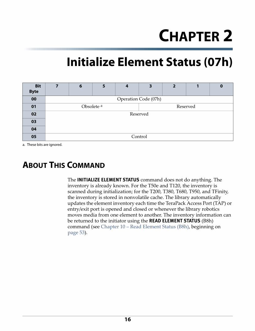
CHAPTER 2Initialize Element Status (07h)
ABOUT THIS COMMAND
The INITIALIZE ELEMENT STATUS command does not do anything. The inventory is already known. For the T50e and T120, the inventory is scanned during initialization; for the T200, T380, T680, T950, and TFinity, the inventory is stored in nonvolatile cache. The library automatically updates the element inventory each time the TeraPack Access Port (TAP) or entry/exit port is opened and closed or whenever the library robotics moves media from one element to another. The inventory information can be returned to the initiator using the READ ELEMENT STATUS (B8h) command (see Chapter 10 – Read Element Status (B8h), beginning on page 53).
BitByte
7 6 5 4 3 2 1 0
00 Operation Code (07h)
01 Obsolete a
a. These bits are ignored.
Reserved
02 Reserved
03
04
05 Control

Chapter 2 — Initialize Element Status (07h) Command Response
April 2015 SCSI Developer’s Guide—Spectra Tape Libraries17
COMMAND RESPONSE
The library returns a status bit in response to the INITIALIZE ELEMENT STATUS command. No data is returned.
COMMAND STATUS
The library returns a status byte after processing the INITIALIZE ELEMENT STATUS command as follows:
GoodThe library returns Good status when it is able to process the command without errors.
BusyBusy status indicates that the library is temporarily unable to accept a command from this initiator. The initiator may retry the command later.
Reservation ConflictThe library returns Reservation Conflict status when it is reserved by a different initiator. See Chapter 14 – Reserve (16h), beginning on page 88 for more information about the RESERVE command.
Check ConditionCheck Condition status is returned for the following reasons:
A Unit Attention condition is pending for the initiator.
The command is issued to an invalid LUN.
The library has experienced an unrecoverable hardware error.
The library encounters a problem while scanning the cartridges.
A reserved bit is set to 1 in the CDB or a parameter in the CDB is invalid (see Table 2‐1 for sense data).
Table 2-1: Sense data for invalid parameters in the INITIALIZE ELEMENT STATUS CDB
Sense Key
ASC ASCQ SKSV Bit
C/D Bit
BPV Bit
Bit Pointer
Field Pointer
Error
5h 24h 00h 1 1 1 — — A reserved bit is set in the CDB. The pointers indicate the bit in error.

18
CHAPTER 3Initialize Element Status With Range
(37h or E7h)
COMMAND DESCRIPTION
INITIALIZE ELEMENT STATUS WITH RANGE is included in the command set for the tape libraries to support the library’s emulation of other libraries.
When the library receives this command, it performs as though it had received the INITIALIZE ELEMENT STATUS (07h) command, ignoring any additional parameters supplied with this command. See Chapter 2 – Initialize Element Status (07h), beginning on page 16 for information about the INITIALIZE ELEMENT STATUS command.
BitByte
7 6 5 4 3 2 1 0
00 Operation Code (E7h or 37h)
01 Reserved Fast a
a. These bits are ignored.
Range b
02 (MSB) Starting Element Address b (LSB)
03
04 Reserved
05
06 (MSB) Number of Elements b (LSB)
07
08 Reserved
09 Control b

19
CHAPTER 4Inquiry (12h)
COMMAND DESCRIPTION
The INQUIRY command requests that the library send information regarding its parameters to the initiator. The library can return the following categories of data in response to this command:
The Standard Inquiry Data page, described starting on page 21, contains basic information about the library, including the product identification.
Note: All of the Spectra Logic tape libraries return SPECTRA PYTHON as the device identifier in response to an INQUIRY command.
The Vital Product Data pages, described starting on page 24, contain additional detailed information about the library. For example, the Unit Serial Number page (Page Code 0x80), described starting on page 25, contains an ASCII representation of the library serial number. Each Vital Product Data page requires a separate INQUIRY command from the initiator.
BitByte
7 6 5 4 3 2 1 0
00 Operation Code (12h)
01 Obsolete a
a. These bits are ignored.
Reserved CMDDT b EVPD
02 Page Code
03 Reserved
04 Allocation Length
05 0 0 Reserved 0 0

Chapter 4 — Inquiry (12h) What You Send to the Library
April 2015 SCSI Developer’s Guide—Spectra Tape Libraries20
WHAT YOU SEND TO THE LIBRARY
The data returned by the INQUIRY command depends on the values of the parameters in the CDB.
Table 4-1: INQUIRY CDB parameter values
Field Name Values Allowed
Meaning
CMDDT(Command Support Data)
0 The library does not support returning optional command support data.
EVPD(Enable Vital Product Data)
0 Requests the Standard Inquiry Data page (described on page 21).
Note: If the EVPD bit is set to 0, the Page Code must be 00h.
1 Request Vital Product Data specific pages (described on page 24), based on the value of the Page Code field (byte 02).
Page Code 00h Requests the Supported Vital Product Data page (described on page 24)
80h Requests the Unit Serial Number page (described on page 25)
83h Requests the Device Identification page (described on page 26)
Allocation Length 00–FFh Specifies the number of bytes that are allocated by the initiator for returned inquiry data. A value of 0 indicates that no inquiry data is to be transferred. This condition is not an error.
The library terminates the Data In phase when it transfers either the number of bytes specified by the Allocation Length field or all of the available inquiry data, whichever is less.
The lengths for inquiry data pages returned by the library are:
Standard Inquiry Data:
26h (36 bytes) if the library is exported by a QIP or RIM
–OR–
3Ah (58 bytes) if the library is exported by a tape drive
Supported Vital Product Data Pages: 08h (8 bytes)
Unit Serial Number: 0Eh (14 bytes)
Device Identification: 36h (54 bytes)

Chapter 4 — Inquiry (12h) Command Response
April 2015 SCSI Developer’s Guide—Spectra Tape Libraries21
COMMAND RESPONSE
The data returned in response to the INQUIRY command depends on the values for the EVPD, Page Code, and Allocation Length fields in the CDB, as described in the following sections.
Standard Inquiry Data Page
When the EVPD bit (byte 01, bit 0) is 0, the library returns either 36 bytes or 58 bytes of Standard Inquiry Data.
BitByte
7 6 5 4 3 2 1 0
00 Peripheral Qualifier Peripheral Device Type
01 RMB Reserved
02 Version (03h)
03 AERC RSVD Norm ACA
HiSup Response Data Format
04 Additional Length
05 SCCS ACC ALUA 3PC Reserved
06 BQue EncServ RSV MultiP MChngr Obsolete Addr16
07 RelAdr Obsolete Wbus16 Sync Linked Obsolete Cmd Que VS
08 (MSB)
... Vendor Identification
15 (LSB)
16 (MSB)
... Product Identification
31 (LSB)
32 (MSB)
... Firmware Revision Level
35 (LSB)
36 (MSB)
Vendor Specific a
(LSB)
...
55
56 Reserved a Clocking a QAS a IUS a
57 Reserved a
a. Only returned when the library is exported by a direct-attached SCSI tape drive.

Chapter 4 — Inquiry (12h) Command Response
April 2015 SCSI Developer’s Guide—Spectra Tape Libraries22
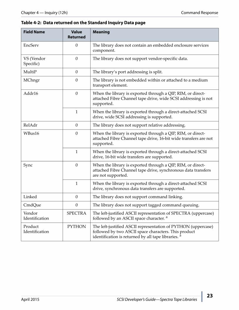
Table 4-2: Data returned on the Standard Inquiry Data page
Field Name Value Returned
Meaning
Peripheral Qualifier
000b The library is a single LUN device. The value of the Logical Unit Number (LUN) field in the CDB must be set to 0h.
Peripheral Device Type
08h Identifies the library as a media changer device.
RMB 1 Indicates media is removable from the library.
Version 03h The library supports the current ANSI version of SPC‐3 (SCSI Primary Commands – 3) standard.
NormACA 0 The library does not support setting the Normal ACA Supported bit to 1.
HiSup 0 The library does not use the hierarchical addressing model to assign LUNs to logical units.
Response Data Format
2h INQUIRY data returned by the library conforms to the format defined in the SPC‐3 Standard.
Additional Length 31 or 53 Indicates the number of bytes of data following this byte.
Libraries exported through QIPs or RIMs return 31 bytes of additional data (Bytes 5 through 35).
Libraries exported through a direct-attached SCSI drive return 53 bytes of additional data (Bytes 5 through 57) which include information from the exporting tape drive (Bytes 36 through 57).
Libraries exported through a direct-attached Fibre Channel drive return 31 bytes of additional data (Bytes 5 through 35).
Notes: Not all tape libraries support direct‐attached SCSI drives.
Refer to the tape drive manufacturer’s SCSI specification for a definition of the vendor specific bytes (Bytes 36 through 55) and the bits for clocking, QAS, and IUS in Byte 56.
SCCS 0 The library does not contain an embedded storage array controller component.
ACC 0 No access controls coordinator may be addressed through this logical unit.
ALUA 0 The SCSI target device does not support asymmetric logical unit access or vendor‐specific asymmetric access. Neither the REPORT TARGET GROUPS command nor the SET TARGET GROUPS command is supported.
3PC 0 The library does not support third‐party copy or EXTENDED COPY commands. A 3PC bit of zero indicates that device support for such commands is disabled.
BQue 0 The library does not support tagged tasks (command queuing).
Chapter 4 — Inquiry (12h) Command Response
April 2015 SCSI Developer’s Guide—Spectra Tape Libraries23
EncServ 0 The library does not contain an embedded enclosure services component.
VS (Vendor Specific)
0 The library does not support vendor‐specific data.
MultiP 0 The library‘s port addressing is split.
MChngr 0 The library is not embedded within or attached to a medium transport element.
Addr16 0 When the library is exported through a QIP, RIM, or direct‐attached Fibre Channel tape drive, wide SCSI addressing is not supported.
1 When the library is exported through a direct‐attached SCSI drive, wide SCSI addressing is supported.
RelAdr 0 The library does not support relative addressing.
WBus16 0 When the library is exported through a QIP, RIM, or direct‐attached Fibre Channel tape drive, 16‐bit wide transfers are not supported.
1 When the library is exported through a direct‐attached SCSI drive, 16‐bit wide transfers are supported.
Sync 0 When the library is exported through a QIP, RIM, or direct‐attached Fibre Channel tape drive, synchronous data transfers are not supported.
1 When the library is exported through a direct‐attached SCSI drive, synchronous data transfers are supported.
Linked 0 The library does not support command linking.
CmdQue 0 The library does not support tagged command queuing.
Vendor Identification
SPECTRA The left‐justified ASCII representation of SPECTRA (uppercase) followed by an ASCII space character. a
Product Identification
PYTHON The left‐justified ASCII representation of PYTHON (uppercase) followed by two ASCII space characters. This product identification is returned by all tape libraries. a
Table 4-2: Data returned on the Standard Inquiry Data page
Field Name Value Returned
Meaning

Chapter 4 — Inquiry (12h) Command Response
April 2015 SCSI Developer’s Guide—Spectra Tape Libraries24
Supported Vital Product Data Page (Page Code 00h)
When the EVPD bit is 1 and the Page Code is 00h, the library returns the Supported Vital Product Data page. The Supported Vital Product Data page lists page codes supported by this device that supply additional Inquiry type data, as described below.
Firmware Revision Level
Varies The left‐justified ASCII representation of the product firmware revision level followed by sufficient ASCII space characters (20h) to fill four bytes.
For example, a firmware version of ASCII 106 requires one space character to fill the four‐byte field; ASCII 2000 fills all four bytes and does not require space characters.
Note: Currently, this field is fixed to 2000 to prevent operating system drivers from reloading when the firmware version changes.
Clocking 0 The device server only supports single timing.
00b b Set if the host interface speed has been set to limit transfers to 80 MB/s.
11b b Set if the host interface speed has not been set to limit transfers to 80 MB/s.
QAS 0 The device server does not support quick arbitration and selection.
IUS 0 The device server does not support information unit transfers.
a. The Vendor Identification and Product Identification data fields change when the library is configured to emulate another vendor’s library.
b. Only supported in libraries exported by a direct-attached Ultra160 SCSI drive.
Table 4-2: Data returned on the Standard Inquiry Data page
Field Name Value Returned
Meaning
BitByte
7 6 5 4 3 2 1 0
00 Peripheral Qualifier Peripheral Device Type
01 Page Code (00h)
02 Reserved
03 Page Length (03h)
04 First Page Code Supported (00h – Supported Vital Product Data page)
05 Second Page Code Supported (80h – Unit Serial Number Data page (see page 25)
06 Third Page Code Supported (83h – Device Identification page (see page 26)
07 Reserved

Chapter 4 — Inquiry (12h) Command Response
April 2015 SCSI Developer’s Guide—Spectra Tape Libraries25
Unit Serial Number Data Page (Page Code 80h)
When the EVPD bit is 1 and the Page Code is 80h, the library returns the Unit Serial Number page as described below.
BitByte
7 6 5 4 3 2 1 0
00 Peripheral Qualifier Peripheral Device Type
01 Page Code (80h)
02 Reserved
03 Page Length
04 (MSB)
... Unit Serial Number (ASCII)
13 (LSB)
Table 4-3: Data returned on the Unit Serial Number Data page
Field Name Value Returned
Meaning
Peripheral Qualifier
000b The library is a single LUN device. The value of the Logical Unit Number (LUN) field in the CDB must be set to 0h.
Peripheral Device Type
08h Identifies the library as a media changer device.
Page Code 80h The current page is the Unit Serial Number Data page.
Page Length 0Ah The length of the serial number.
Serial Number Varies The 10 byte null terminated ASCII representation of the library serial number.

Chapter 4 — Inquiry (12h) Command Response
April 2015 SCSI Developer’s Guide—Spectra Tape Libraries26
Device Identification Page (Page Code 83h)
The Device Identification page allows the library to report its device identifiers, including its product identifier and serial number. The library returns the Device Identification page when the EVPD bit in the CDB is 1 and the Page Code is 83h
BitByte
7 6 5 4 3 2 1 0
00 Peripheral Qualifier Peripheral Device Type
01 Page Code (83h)
02 Reserved
03 Page Length
04 Reserved Code Set
05 Reserved Identifier Type
06 Reserved
07 Identifier Length
08 (MSB)
... Vendor Identification
15 (LSB)
16 (MSB)
... Product Identification
31 (LSB)
32 (MSB)
... Unit Serial Number
41 (LSB)
42 Reserved Code Set – Node a
43 Reserved Association – Node a Identifier Type – Node a
44 Reserved
45 Identifier Length – Node (8h) a
46 (MSB)
Node Identifier a
(LSB)
...
53
a. Applicable only to Fibre Channel and Gigabit Ethernet (iSCSI) libraries. These fields are not returned on SCSI interface systems.

Chapter 4 — Inquiry (12h) Command Response
April 2015 SCSI Developer’s Guide—Spectra Tape Libraries27
.
Table 4-4: Data returned on the Device Identification page
Field Name Value Returned
Meaning
Peripheral Qualifier
000b The library is a single LUN device. The value of the Logical Unit Number (LUN) field in the CDB must be set to 0h.
Peripheral Device Type
08h Identifies the library as a media changer device.
Page Code 83h The current page is the Device Identification page.
Page Length 26h A library (partition) exported through a direct‐attached SCSI drive returns 38 (26h) bytes following the Page Length byte.
Note: Not all tape libraries support direct‐attached SCSI drives.
32h A library (partition) exported through a QIP or RIM returns 50 (32h) bytes following the Page Length byte.
Code Set 02h The Identifier field (bytes 08 through 43) contains ASCII data.
Identifier Type 01h The T10 vendor ID (ASCII) Name_Identifier.
Identifier Length 22h The identifier returned by the library is 34 (22h) bytes in length.
Vendor Identification
SPECTRA a The left‐justified ASCII representation of SPECTRA (uppercase) followed by an ASCII space character.
Product Identification
PYTHON a The left‐justified ASCII representation of PYTHON (uppercase) followed by two ASCII space characters. This product identification is returned by all tape libraries unless emulation is configured.
Unit Serial Number Variable b The 10 byte null terminated ASCII representation of the library serial number.
Code Set—Node 01h The Node Identifier field (bytes 48 through 55) contains binary data.
Identifier Type—Node
03h The Node Identifier contains an FC_PH Name_Identifier (WWN) associated with the port that received the request (the node).
Identifier Length—Node
08h The identifier returned by the library is 8 bytes in length.
Node Identifier c Variable The 64‐bit WWN of the exporting QIP, RIM, or direct‐attached Fibre Channel tape drive port that received the request.
a. The data returned in the Vendor Identification and Product Identification data fields changes when the library is configured to emulate another vendor’s library.
b. The serial number can be up to 10 characters in length.c. This field is valid only for libraries exported by a Fibre Channel QIP (F-QIP) or RIM and for Fibre Channel drives.

Chapter 4 — Inquiry (12h) Command Status
April 2015 SCSI Developer’s Guide—Spectra Tape Libraries28
COMMAND STATUS
The library returns a status byte after processing the INQUIRY command. This section describes when each type of status byte might be returned.
Good
The library returns Good status when it is able to process the command without errors.
Busy
The library never returns Busy status for the INQUIRY command.
Reservation Conflict
The library never returns Reservation Conflict status for the INQUIRY command.
Check Condition
The library returns Check Condition status for the following reasons:
A reserved bit is set to 1 in the CDB.
A parameter in the CDB is invalid (see Table 4‐5 for sense data).
Table 4-5: Invalid parameters in the INQUIRY CDB
Sense Key
ASC ASCQ
SKSV Bit
C/D Bit
BPV Bit
Bit Pointer
Field Pointer
Error
5h 24h 00h 1 1 1 — — A reserved bit is set in the CDB. The pointers indicate the bit in error.
5h 24h 00h 1 1 0 0 00 02h Invalid Page Code.
5h 24h 00h 1 1 1 7 00 02h Page value set but EVPD is 0.
29
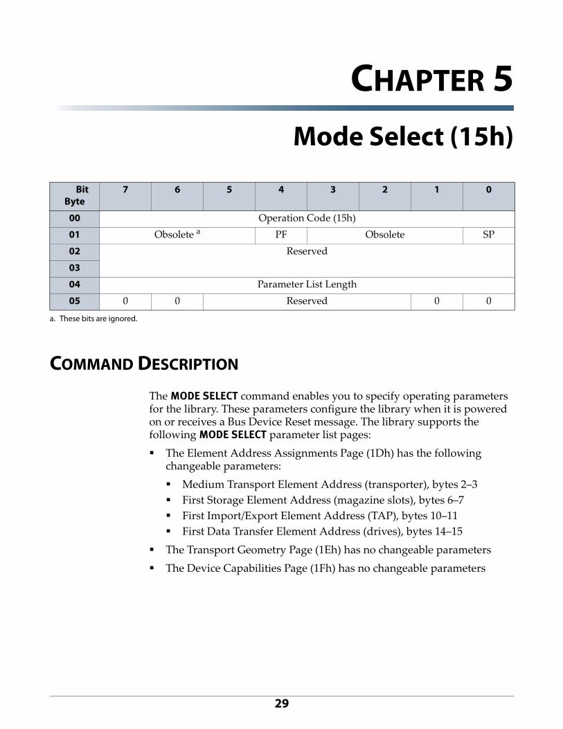
CHAPTER 5Mode Select (15h)
COMMAND DESCRIPTION
The MODE SELECT command enables you to specify operating parameters for the library. These parameters configure the library when it is powered on or receives a Bus Device Reset message. The library supports the following MODE SELECT parameter list pages:
The Element Address Assignments Page (1Dh) has the following changeable parameters:
Medium Transport Element Address (transporter), bytes 2–3
First Storage Element Address (magazine slots), bytes 6–7
First Import/Export Element Address (TAP), bytes 10–11
First Data Transfer Element Address (drives), bytes 14–15
The Transport Geometry Page (1Eh) has no changeable parameters
The Device Capabilities Page (1Fh) has no changeable parameters
BitByte
7 6 5 4 3 2 1 0
00 Operation Code (15h)
01 Obsolete a
a. These bits are ignored.
PF Obsolete SP
02 Reserved
03
04 Parameter List Length
05 0 0 Reserved 0 0

Chapter 5 — Mode Select (15h) What you Send to the Library
April 2015 SCSI Developer’s Guide—Spectra Tape Libraries30
Any changed parameters apply to all initiators in a multi‐initiator environment. If mode parameters are changed, the library generates a Unit Attention message to all initiators, except the one that issued the MODE SELECT command, with sense information to indicate that mode parameters have changed.
Notes: Before issuing any MODE SELECT command, issue a MODE SENSE command (see Mode Sense (1Ah) on page 36) with the following values in the CDB:
Page Code = 3Fh—Causes the library to return all mode pages.
Page Control = 01—Causes the library to indicate which fields are changeable.
The recommended timeout for this command is 20 minutes or 1200 seconds.
WHAT YOU SEND TO THE LIBRARY
To change parameter values, send a MODE SELECT command with the following parameters, followed by a parameter list in the Data Out phase.
Table 5-1: MODE SELECT CDB parameter values
Field Name Values Allowed
Meaning
PF 1 The library supports the page format defined by the SPC‐3 standard.
SP (Save Pages)
0 Current configuration values are changed to the values sent to the library. Saved values stored in nonvolatile memory are not affected. The default values are restored when the device is reset or power cycled.
1 a Current configuration values are changed to the values sent to the library and saved in nonvolatile memory.
Parameter List Length
00–FFh This field indicates the length of the entire parameter list. The parameter list length is equal to the length of one Parameter List Header (4 bytes) plus the lengths of all pages to be transferred.
When the value of the parameter list length is 00h, no parameter list is transferred from the initiator. This is not considered an error.
The data length for all mode parameter pages returned by the library is 48 bytes (30h).
Notes: A parameter list length of 4 is not valid. When you send the Parameter List Header, you must send at least one page with it.
Before issuing a MODE SELECT command, issue a MODE SENSE command (see Mode Sense (1Ah) on page 36) with the Page Control field set to 1 and the Page Code field set to 3Fh. This allows you to determine the supported pages, the changeable parameters within the pages, and the supported length of each page.
a. This is only allowed for page 1Dh.

Chapter 5 — Mode Select (15h) What you Send to the Library
April 2015 SCSI Developer’s Guide—Spectra Tape Libraries31
Mode Parameter Lists
During the Data Out phase following the command block the initiator sends the Parameter List Header, followed by one or more parameter list pages containing the new parameter values of the library.
Parameter List Header
If you send one or more parameter pages with the MODE SELECT command, you must send a Parameter List Header. Do not send the Parameter List Header if you are not sending any parameter pages.
All fields of the Parameter List Header are reserved and must be set to zero.
BitByte
7 6 5 4 3 2 1 0
00 Reserved
01
02
03

Chapter 5 — Mode Select (15h) What you Send to the Library
April 2015 SCSI Developer’s Guide—Spectra Tape Libraries32
Element Address Assignment Page (Page Code 1Dh)
The library only supports changing the element addresses.
Important The element addresses for the elements in an element group must not overlap the addresses for other element groups.
Important The elements in an element group (that is, cartridge slots, robotics, and drives) must be assigned contiguous addresses.
Important Element addresses must be between 0 and 65,535 (FFFFh).
BitByte
7 6 5 4 3 2 1 0
00 PS Reserved Page Code (1Dh)
01 Parameter Length (12h)
02 (MSB) Medium Transport Element Address(default=00 01h) (LSB)03
04 (MSB) Number of Medium Transport Elements a
(fixed at 01h for all tape libraries) (LSB)05
06 (MSB) First Storage Element Address(default=10 00h) (LSB)07
08 (MSB) Number of Storage Elements a
(depends on partition size) (LSB)09
10 (MSB) First Import/Export Element Address(default=0010h) (LSB)11
12 (MSB) Number of Import/Export Elements a
(depends on partition configuration) (LSB)13
14 (MSB) First Data Transfer Element Address(default=0100h) (LSB)15
16 (MSB) Number of Data Transfer Elements a
(depends on partition size) (LSB)17
18 Reserved
19
a. The data MUST match the response from MODE SENSE page 1Dh. It cannot be set to zero.

Chapter 5 — Mode Select (15h) What you Send to the Library
April 2015 SCSI Developer’s Guide—Spectra Tape Libraries33
Table 5-2: Data sent on the Element Address Assignment page
Field Name Value Meaning
PS(Pages Saveable)
0 The Element Address Parameter page can be saved to nonvolatile memory by setting the SP field in the MODE SELECT command.
Page Code 1Dh Identifies the Element Address Assignment page.
Parameter List Length
12h (18) Indicates that there are an additional 18 bytes of element address data that follow this byte.
Medium Transport Element Address
Varies Indicates the element address for the medium transport element (the transporter). The default value is 00 01h.
Number of Medium Transport Elements
01h a The library has only one medium transport element (the transporter). This is also true for libraries that may have more than one physical robot like the TFinity.
First Storage Element Address
Varies Indicates the element address for the first storage element (magazine slot) in the logical library (partition). The default is 10 00h (4096).
Number of Storage Elements
Varies a Indicates the configured number of storage locations (magazine slots) within the logical library (partition).
Note: This parameter depends on partition size and cannot be changed.
First Import/Export Element Address
Varies Indicates the element address of the first import/export element. The default is 00 10h (16).
Number of Import/Export Elements
Varies a Indicates the total number of locations (slots) used for importing and exporting cartridges into and out of the logical library (partition).
Notes: This parameter depends on partition configuration and cannot be changed.
For all tape libraries except the T120 and the T50e, the import/export elements are the slots assigned to the entry/exit pool for the partition.
For the T120 and the T50e libraries, the import/export elements are the slots in the entry/exit port.
First Data Transfer Element Address
Varies Indicates the element address of the first data transfer element (a drive). The default is 01 00h (256).
Number of Data Transfer Elements
Varies a Indicates the total number of data transfer elements.
Note: This parameter depends on partition size and cannot be changed.
a. The data MUST match the response from MODE SENSE page 1Dh. It cannot be set to zero.

Chapter 5 — Mode Select (15h) Command Status
April 2015 SCSI Developer’s Guide—Spectra Tape Libraries34
COMMAND STATUS
The library returns a status byte after processing the MODE SELECT command. This section describes when each type of status byte might be returned.
Good
The library returns Good status when it is able to process the command without errors (that is, when the requested MODE SELECT parameters have been copied over the current MODE SELECT settings).
Busy
Busy status indicates that the library is temporarily unable to accept a command from this initiator. The initiator may retry the command later.
Reservation Conflict
The library returns Reservation Conflict status when it is reserved by a different initiator. See Chapter 14 – Reserve (16h), beginning on page 88 for more information about the RESERVE command.

Chapter 5 — Mode Select (15h) Command Status
April 2015 SCSI Developer’s Guide—Spectra Tape Libraries35
Check Condition
The library returns Check Condition status for the following reasons:
The command is issued to an invalid LUN.
A Unit Attention condition is pending for the initiator.
A reserved bit is set to 1 in the CDB.
The library detects an unrecoverable parity error while receiving the MODE SELECT data.
A parameter in the CDB on a MODE SELECT page is invalid (see Table 5‐3 for sense data).
Table 5-3: Invalid parameters in the MODE SELECT CDB and mode data
Sense Key
ASC ASCQ SKSV Bit
C/D Bit
BPV Bit
Bit Pointer
Field Pointer
Error
5h 1Ah 00h 1 1 0 0 00 04h Invalid Parameter List Length.
5h 21h 01h 1 0 0 0 a Address overlap. The field pointer is set to 00 0Ah, indicating that there is an address overlap for a Storage Element Address in the Element Address Assignment page.
5h 24h 00h 1 1 1 — — A reserved bit is set in the CDB. The pointers indicate the bit in error.
5h 24h 00h 1 1 1 4h 00 01h Invalid PF (page format). Must be set to 1.
5h 26h 00h 1 0 0 0 a Invalid values in the Parameter List Header. All values must be 0. The value of the field pointer is the value of the first field that contains a non‐zero value (00, 01, 02, or 03).
Invalid Parameter Length.
Reserved bits set in the reserved fields 22 or 23 (bytes 18 or 19 of the Element Address Assignment page).
Storage element addresses are not consecutive.
Address wrap. Number of elements causes the address range to wrap back to 00 00.
5h 26h 00h 1 0 1 5h a Invalid Page Code.
5h 26h 00h 1 0 1 7h a Reserved bits set in the first byte of one of the MODE SELECT pages.
a. Field pointer depends on the order in which the pages are sent.

36
CHAPTER 6Mode Sense (1Ah)
The SPC‐3 Standard provides both a 6‐byte and a 10‐byte MODE SENSE command. Spectra tape libraries only support both the 6 byte MODE SENSE command.
COMMAND DESCRIPTION
The MODE SENSE command enables the library to report its operating mode parameters to the initiator. The initiator can request one or all of the supported mode pages. Each response includes four bytes for the Parameter List Header, followed by the specified number of bytes for each page:
20 bytes for the Element Address Assignment page (1Dh)
4 bytes for the Transport Geometry Descriptor page (1Eh)
20 bytes for the Device Capabilities page (1Fh)
These pages are described in detail under Command Response on page 38.
You can change the element address parameters on the Element Address Assignment page using the MODE SELECT (15h) command (see Chapter 5 – Mode Select (15h), beginning on page 29). The Transport Geometry Descriptor page and the Device Capabilities page do not have any changeable parameters.
Note: The recommended timeout for this command is 20 minutes or 1200 seconds.
BitByte
7 6 5 4 3 2 1 0
00 Operation Code (1Ah)
01 Obsolete a Reserved DBD Reserved
02 PC Page Code
03 Reserved
04 Allocation Length
05 0 0 Reserved 0 0 0
a. These bits are ignored.

Chapter 6 — Mode Sense (1Ah) What You Send to the Library
April 2015 SCSI Developer’s Guide—Spectra Tape Libraries37
WHAT YOU SEND TO THE LIBRARY
The data returned by the MODE SENSE command depends on the values of the parameters in the CDB.
Table 6-1: MODE SENSE CDB parameter values.
Field Name Values Allowed
Meaning
DBD(Disable Block Descriptors)
0 or 1 The library does not return block descriptors even if requested to do so. This is not an error condition. The library always returns a block descriptor length of 0.
Page Control 0 (00b) Requests the current parameter values. The current values returned are:
The parameters set in the last successful MODE SELECT command.
The saved values, if a MODE SELECT command has not been executed since the last power‐on or reset.
The default values, if saved values are not available.
1 (01b) Requests the changeable parameters. The pages you request are returned and indicate which parameters you can change. All bits of parameters that you can change are set to 1. All bits of parameters that you cannot change are set to 0. The Page Code and Parameter List Length fields contain actual values.
Note: Before issuing a MODE SELECT command, issue a MODE SENSE command with the PC field set to 1 and the Page Code field set to 3Fh. This allows you to determine the supported pages, the changeable parameters within the pages, and the supported length of each page.
2 (10b) Requests default values. The pages you request are returned with the default value for each supported parameter. Parameters that are not supported by the library are set to 0.
3 (11b) Requests saved values. The pages you request are returned with the saved setting for each supported parameter. Parameters that are not supported by the library are set to 0.
Note: If changes to the page have not been saved, the library returns the current values.
Page Code 3Fh Requests that the library return all available mode pages.
1Dh Requests Element Address Assignment page only.
1Eh Requests Transport Geometry Parameters page only.
1Fh Requests Device Capabilities page only.
00h Not used.

Chapter 6 — Mode Sense (1Ah) Command Response
April 2015 SCSI Developer’s Guide—Spectra Tape Libraries38
COMMAND RESPONSE
This section describes the page structure for mode data and the pages that the library supports. The MODE SENSE command returns a single mode data page or all mode data pages as specified in the Page Code field of the CDB. Each mode data page begins with a four‐byte Parameter List Header, followed by zero or more variable‐length mode data parameters defined for the specified page.
If all mode pages are requested, the library returns 48 bytes of mode sense data to the initiator, structured as follows:
4 bytes of Parameter List Header data
20 bytes of Element Address Assignments data
4 bytes of Transport Geometry Descriptors data
20 bytes of Device Capabilities Parameters data
Note: When a specific page is requested, the library returns only the Parameter List Header data and the specified page.
Parameter List Header
6-Byte
Mode Data Length indicates the number of bytes of parameter information following the Mode Data Length byte. For the 6‐Byte SCSI command, if all mode pages are requested, this value is 44 (2Ch).
Allocation Length 00–FFh Specifies the length of the parameter list the library will return. The maximum length required to receive all pages is 48 bytes (30h). No mode data is transferred if you specify zero. This condition is not considered an error. The library terminates the Data In phase when it transfers either the number of bytes specified by the Allocation Length or when all available MODE SENSE data have been transferred, whichever is less.
Table 6-1: MODE SENSE CDB parameter values.
Field Name Values Allowed
Meaning
BitByte
7 6 5 4 3 2 1 0
00 Mode Data Length
01 Reserved
02
03

Chapter 6 — Mode Sense (1Ah) Command Response
April 2015 SCSI Developer’s Guide—Spectra Tape Libraries39
Element Address Assignment Page (Page Code 1Dh)
The library returns the following data for the Element Address Assignment page. See Elements and Element Addresses on page 13 for additional information.
Note: If the library (or partition) is configure to emulate another vendor’s library, the format of the element address data returned by this page may change.
BitByte
7 6 5 4 3 2 1 0
00 PS Reserved Page Code (1Dh)
01 Parameter Length (12h)
02 (MSB) Medium Transport Element Address(default=00 01h) (LSB)03
04 (MSB) Number of Medium Transport Elements (fixed at 01h for all tape libraries) (LSB)05
06 (MSB) First Storage Element Address(default=10 00h) (LSB)07
08 (MSB) Number of Storage Elements(depends on partition size) (LSB)09
10 (MSB) First Import/Export Element Address(default=0010h) (LSB)11
12 (MSB) Number of Import/Export Elements(depends on configuration) (LSB)13
14 (MSB) First Data Transfer Element Address(default=0100h) (LSB)15
16 (MSB) Number of Data Transfer Elements(depends on partition size) (LSB)17
18 Reserved
19

Chapter 6 — Mode Sense (1Ah) Command Response
April 2015 SCSI Developer’s Guide—Spectra Tape Libraries40
Table 6-2: Data returned on the Element Address Assignment page
Field Name Value Returned
Meaning
PS(Pages Saveable)
1 The Element Address Assignment page can be saved to nonvolatile memory by setting the SP field in the MODE SELECT command. See Chapter 5 – Mode Select (15h), beginning on page 29 for details.
Page Code 1Dh Identifies the Element Address Assignment page.
Parameter List Length
12h (18) Indicates that there are an additional 18 bytes of element address data that follow this byte.
Medium Transport Element Address
Varies Indicates the element address for the medium transport element (the transporter). The default value is 00 01h.
Number of Medium Transport Elements
01h The library has only one medium transport element (the transporter). This is also true for libraries that may have more than one physical robot like the TFinity.
First Storage Element Address
Varies Indicates the starting address for the storage elements (magazine slots) in the logical library (partition). The default starting address is 10 00h (4096). You can change this address with the MODE SELECT (15h) command.
Number of Storage Elements
Varies a Indicates the configured number of storage locations (magazine slots) within the logical library (partition).
First Import/Export Element Address
Varies Indicates the element address of the first import/export element. The default is 00 10h (16).
Number of Import/Export Elements
Varies b Indicates the total number of locations (slots) used for importing and exporting cartridges into and out of the logical library (partition).
Notes: For all tape libraries except the T120 and the T50e, the import/export elements are the slots assigned to the entry/exit pool for the partition.
For the T120 and the T50e libraries, the import/export elements are the slots in the entry/exit port.
First Data Transfer Element Address
Varies Indicates the element address of the first data transfer element (a drive). The default is 01 00h (256).
Number of Data Transfer Elements
Varies b Indicates the total number of data transfer elements.
a. Depends on the partition size.b. Depends on the partition configuration.

Chapter 6 — Mode Sense (1Ah) Command Response
April 2015 SCSI Developer’s Guide—Spectra Tape Libraries41
Transport Geometry Parameters (Page Code 1Eh)
The library returns the following data for the Transport Geometry Parameter page.
Note: The parameters on the Transport Geometry Parameter page cannot be changed using a MODE SELECT command.
BitByte
7 6 5 4 3 2 1 0
00 PS Reserved Page Code (1Eh)
01 Parameter Length
02 Reserved Rotate
03 Member Number in Transport Element Set
Table 6-3: Data returned on the Transport Geometry Parameter page
Field Name Value Returned
Meaning
PS(Pages Saveable)
0 The Transport Geometry Parameter page cannot be saved to nonvolatile memory.
Page Code 1Eh Identifies the Transport Geometry Parameter page.
Parameter List Length
02h Indicates the number of additional bytes of transport geometry descriptor data that follow the header. Each descriptor consists of two bytes of information. The library has only one transport mechanism (transporter), so the value returned for this field is always 02h even for libraries that have more than one physical robot like the TFinity.
Rotate 0b Indicates the ability of the transport mechanism to handle two‐sided media. The library only uses one‐sided media, so the value returned for this field is always 0.
Member Number in Transport Element Set
00h Indicates the specific transport element in the system to which this descriptor is applied. The library has only one medium transport element, so the value returned for this field is always 0. This is true even for libraries that may have more than one physical robot like the TFinity.

Chapter 6 — Mode Sense (1Ah) Command Response
April 2015 SCSI Developer’s Guide—Spectra Tape Libraries42
Device Capabilities Page (Page Code 1Fh)
The library returns the following data for the Device Capabilities page.
Note: The parameters on the Device Capabilities page cannot be changed using a MODE SELECT command.
BitByte
7 6 5 4 3 2 1 0
00 PS RSVD Page Code (1Fh)
01 Parameter Length (12h)
02 Reserved DT1
I/E1
ST1
MT0
03 Reserved
04 Reserved MTDT1
MTI/E1
MTST1
MTMT0
05 Reserved STDT1
STI/E1
STST1
STMT0
06 Reserved I/EDT1
I/EI/E1
I/EST1
I/EMT0
07 Reserved DTDT1
DTI/E1
DTST1
DTMT0
08 Reserved
...
11
12 Reserved (0) MTDT
0
MTIE
0
MTST
0
MTMT
0
13 STDT
0
STIE
0
STST
0
STMT
0
14 IEDT
0
IEIE
0
IEMT
0
IEMT
0
15 DTDT
0
DTIE
0
DTST
0
DTMT
0
16 Reserved
...
19
Chapter 6 — Mode Sense (1Ah) Command Response
April 2015 SCSI Developer’s Guide—Spectra Tape Libraries43
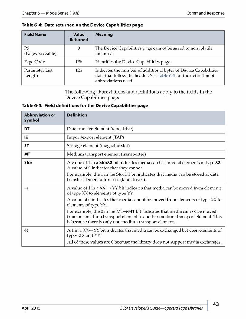
The following abbreviations and definitions apply to the fields in the Device Capabilities page:
Table 6-4: Data returned on the Device Capabilities page
Field Name Value Returned
Meaning
PS(Pages Saveable)
0 The Device Capabilities page cannot be saved to nonvolatile memory.
Page Code 1Fh Identifies the Device Capabilities page.
Parameter List Length
12h Indicates the number of additional bytes of Device Capabilities data that follow the header. See Table 6‐5 for the definition of abbreviations used.
Table 6-5: Field definitions for the Device Capabilities page
Abbreviation or Symbol
Definition
DT Data transfer element (tape drive)
IE Import/export element (TAP)
ST Storage element (magazine slot)
MT Medium transport element (transporter)
Stor A value of 1 in a StorXX bit indicates media can be stored at elements of type XX. A value of 0 indicates that they cannot.
For example, the 1 in the StorDT bit indicates that media can be stored at data transfer element addresses (tape drives).
A value of 1 in a XX YY bit indicates that media can be moved from elements of type XX to elements of type YY.
A value of 0 indicates that media cannot be moved from elements of type XX to elements of type YY.
For example, the 0 in the MTMT bit indicates that media cannot be moved from one medium transport element to another medium transport element. This is because there is only one medium transport element.
A 1 in a XXYY bit indicates that media can be exchanged between elements of types XX and YY.
All of these values are 0 because the library does not support media exchanges.
Chapter 6 — Mode Sense (1Ah) Command Status
April 2015 SCSI Developer’s Guide—Spectra Tape Libraries44
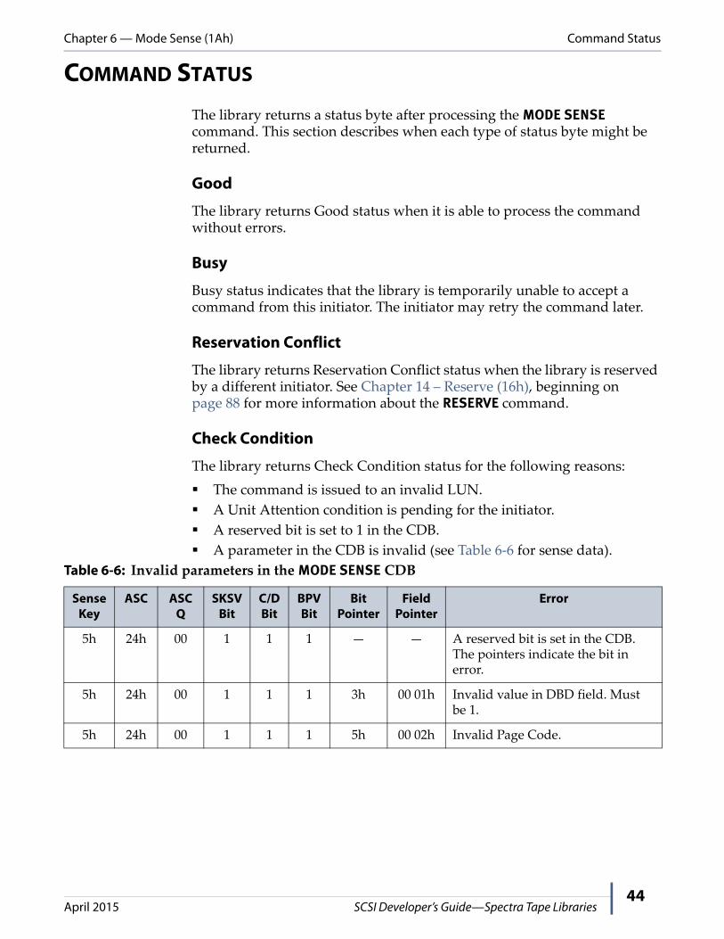
COMMAND STATUS
The library returns a status byte after processing the MODE SENSE command. This section describes when each type of status byte might be returned.
Good
The library returns Good status when it is able to process the command without errors.
Busy
Busy status indicates that the library is temporarily unable to accept a command from this initiator. The initiator may retry the command later.
Reservation Conflict
The library returns Reservation Conflict status when the library is reserved by a different initiator. See Chapter 14 – Reserve (16h), beginning on page 88 for more information about the RESERVE command.
Check Condition
The library returns Check Condition status for the following reasons:
The command is issued to an invalid LUN.
A Unit Attention condition is pending for the initiator.
A reserved bit is set to 1 in the CDB.
A parameter in the CDB is invalid (see Table 6‐6 for sense data).
Table 6-6: Invalid parameters in the MODE SENSE CDB
Sense Key
ASC ASCQ
SKSV Bit
C/D Bit
BPV Bit
Bit Pointer
Field Pointer
Error
5h 24h 00 1 1 1 — — A reserved bit is set in the CDB. The pointers indicate the bit in error.
5h 24h 00 1 1 1 3h 00 01h Invalid value in DBD field. Must be 1.
5h 24h 00 1 1 1 5h 00 02h Invalid Page Code.

45
CHAPTER 7Move Medium (A5h)
COMMAND DESCRIPTION
The MOVE MEDIUM command requests that the library move media from one element location to another. The locations are identified by their element addresses. For the valid source element and destination element combinations for the MOVE MEDIUM command, see Device Capabilities Page (Page Code 1Fh) on page 42.
Send a READ ELEMENT STATUS command to the library to determine the current element addresses and which elements contain media (see Chapter 10 – Read Element Status (B8h), beginning on page 53).
Note: The recommended timeout for this command is 20 minutes or 1200 seconds per library partition.
BitByte
7 6 5 4 3 2 1 0
00 Operation Code (A5h)
01 Obsolete a
a. These bits are ignored.
Reserved
02 (MSB) Transport Element Address
(LSB)03
04 (MSB) Source Address
(LSB)05
06 (MSB) Destination Address
(LSB)07
08 Reserved
09
10 Reserved Invert
11 0 0 Reserved 0 0 0

Chapter 7 — Move Medium (A5h) What You Send to the Library
April 2015 SCSI Developer’s Guide—Spectra Tape Libraries46
WHAT YOU SEND TO THE LIBRARY
The behavior of the library in response to the MOVE MEDIUM command depends on the values of the parameters in the CDB.
COMMAND STATUS
The library returns a status byte after processing the MOVE MEDIUM command.
Good
The library returns Good status when it is able to process the command without errors.
Busy
Busy status indicates that the library is temporarily unable to accept a command from this initiator. The initiator may retry the command later.
Reservation Conflict
The library returns Reservation Conflict status when it is reserved by a different initiator. See Chapter 14 – Reserve (16h), beginning on page 88 for more information about the RESERVE command.
Table 7-1: MOVE MEDIUM CDB field values
Field Name Values Allowed
Meaning
Transport Element Address
Varies a The element address of the picker (the default is 00 01h).
This value should match the value from MODE SENSE or be 00 00h.
Source Address Varies a The current element address of the slot or drive where the cartridge is located.
Destination Address b
Varies a The element address of the slot or drive where the cartridge will be moved.
Invert 0 tape libraries use single‐sided media and do not support the invert function.
a. Permitted values for the Transport Element Address, Source Address, and Destination Address can be changed with the MODE SELECT command (see Chapter 5 – Mode Select (15h), beginning on page 29). Use the MODE SENSE command to determine the current element address settings, including the default element addresses (see Chapter 6 – Mode Sense (1Ah), beginning on page 36).
b. Moves to or from the medium transport element (transporter) are not allowed.

Chapter 7 — Move Medium (A5h) Command Status
April 2015 SCSI Developer’s Guide—Spectra Tape Libraries47
Check Condition
The library returns Check Condition status for the following reasons:
A Unit Attention condition is pending for the initiator.
The library has experienced an unrecoverable hardware error.
A reserved bit is set to 1 in the CDB.
The information in the cartridge inventory indicates that the requested cartridge move operation cannot be performed.
After the library attempts to move a cartridge, it finds that the source is empty or the destination is occupied.
The library encounters a problem while trying to move a cartridge. For example, it encounters a place or put error while moving a cartridge.
A parameter in the CDB is invalid (see Table 7‐2 for sense data).
Table 7-2: Invalid parameters in the MOVE MEDIUM CDB and move errors
Sense Key
ASC ASCQ SKSV Bit
C/D Bit
BPV Bit
Bit Pointer
Field Pointer
Error
3h 53h 00h 0 0 0 0 0 Media load or eject failed
4h 85h 01h Move failed; tape left in picker.
4h 85h 02h Move failed; tape left in source.
5h 21h 01h 1 1 0 0 00 02h Invalid transport element address.
5h 21h 01h 1 1 0 0 00 04h Invalid source element address.
5h 21h 01h 1 1 0 0 00 06h Invalid destination element address.
5h 24h 00 1 1 1 0 00 0Ah Invalid Invert field.
5h 24h 00h 1 1 1 — — A reserved bit is set in the CDB. The pointers indicate the bit in error.
5h 3Bh 0Dh 0 0 0 0 0 Destination element is occupied.
5h 3Bh 0Eh 0 0 0 0 0 Source element is empty.
5h 3Bh 11h Media magazine not accessible. This will only occur in libraries with TeraPack magazines.
5h 80h 05h 0 0 0 0 0 Source drive not installed.
5h 80h 06h 0 0 0 0 0 Destination drive not installed.
5h 80h 18h Reservation conflict. Element is reserved. This occurs when the slot is reserved by the front panel for queued ejects. See Overview of T120 and T50e Entry/Exit Modes on page 73.

48
CHAPTER 8Prevent/Allow Medium Removal (1Eh)
COMMAND DESCRIPTION
The PREVENT/ALLOW MEDIUM REMOVAL command requests that the library enable or disable removal of media through the import/export elements.
WHAT YOU SEND TO THE LIBRARY
The library behavior as a result of the PREVENT/ALLOW MEDIUM REMOVAL command depends on the value of the Prevent bit in the CDB.
Note: When the Prevent bit is set to 01b, media cannot be accessed in the import/export elements until one of the following occurs:
All initiators that have issued PREVENT MEDIUM REMOVAL commands issue ALLOW MEDIUM REMOVAL commands with the Prevent bit set to 0.
The library is reset.
BitByte
7 6 5 4 3 2 1 0
00 Operation Code (1Eh)
01 Obsolete a
a. These bits are ignored.
Reserved
02 Reserved
03
04 Reserved Prevent
05 0 0 Reserved 0 0 0
Table 8-1: PREVENT/ALLOW MEDIUM REMOVAL CDB parameter values
Field Name Values Allowed
Meaning
Prevent 0 (00b) Media removal is allowed.
1 (01b) Media removal is prevented.

Chapter 8 — Prevent/Allow Medium Removal (1Eh) Command Status
April 2015 SCSI Developer’s Guide—Spectra Tape Libraries49
COMMAND STATUS
The library returns a status byte after processing the PREVENT/ALLOW MEDIUM REMOVAL command. This section describes when each type of status byte might be returned.
Good
The library returns Good status when it is able to process the command without errors.
Busy
Busy status indicates that the library is temporarily unable to accept a command from this initiator. The initiator may retry the command later.
Reservation Conflict
The library returns Reservation Conflict status when it is reserved by a different initiator and a request is made to prevent medium removal. See Chapter 14 – Reserve (16h), beginning on page 88 for more information about the RESERVE command.
Check Condition
The library returns Check Condition status when:
A Unit Attention condition is pending for the initiator.
A reserved bit is set to 1 in the CDB
Table 8-2: Invalid parameters in the PREVENT/ALLOW MEDIUM REMOVAL CDB
Sense Key
ASC ASCQ SKSV Bit
C/D Bit
BPV Bit
Bit Pointer
Field Pointer
Error
5h 24h 00h 1 1 1 — — A reserved bit is set in the CDB. The pointers show the bit in error.
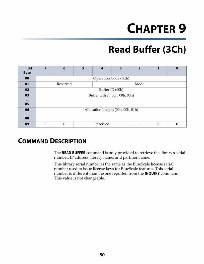
50
CHAPTER 9Read Buffer (3Ch)
COMMAND DESCRIPTION
The READ BUFFER command is only provided to retrieve the library’s serial number, IP address, library name, and partition name.
This library serial number is the same as the BlueScale license serial number used to issue license keys for BlueScale features. This serial number is different than the one reported from the INQUIRY command. This value is not changeable.
Bit Byte
7 6 5 4 3 2 1 0
00 Operation Code (3Ch)
01 Reserved Mode
02 Buffer ID (00h)
03...05
Buffer Offset (00h, 00h, 00h)
06...08
Allocation Length (00h, 00h, 01h)
09 0 0 Reserved 0 0 0

Chapter 9 — Read Buffer (3Ch) Command Response
April 2015 SCSI Developer’s Guide—Spectra Tape Libraries51
What You Send to the Library
The following parameters set the READ BUFFER command to retrieve the library’s serial number.
The following parameters set the READ BUFFER command to retrieve the library’s IP address, library name, and partition name.
COMMAND RESPONSE
For Buffer ID 00h, the 16‐byte response returned by the library is the library serial number, left justified with trailing zeros (0).
For Buffer ID 01h, the data returned is:
Four bytes of IP address
65 bytes for the Library Name
33 bytes for the Partition Name
Table 9-1: READBUFFER CDB field values
Field Name Values Allowed
Meaning
Mode 02h Set mode to data only. This is the preferred method.
03h Set mode to descriptor only.
Buffer ID 00h Specifies the buffer ID for the library serial number.
Buffer Offset 00 00 00 h Specifies the buffer offset for the library serial number. The library does not support buffer offsets. This value must be set to 0.
Allocation Length 00 00 10 h Specifies the length of the data returned. For the library serial number, the recommended value is 00 00 10h.
Table 9-2: READBUFFER CDB field values
Field Name Values Allowed
Meaning
Mode 02h Set mode to data only. This is the preferred method.
03h Set mode to descriptor only.
Buffer ID 01h Specifies the buffer ID for the library IP address, library name, and partition name.
Buffer Offset 00 00 00 h Specifies the buffer offset for the data returned. The library does not support buffer offsets. This value must be set to 0.
Allocation Length 00 00 66 h Specifies the length of the data returned. For the libraryʹs IP address, library name, and partition name, the value is 00 00 66 h.

Chapter 9 — Read Buffer (3Ch) Command Status
April 2015 SCSI Developer’s Guide—Spectra Tape Libraries52
COMMAND STATUS
The library returns a status byte after processing the READ BUFFER command. This section describes when each type of status byte might be returned.
Good
The library returns Good status when it is able to process the command without errors.
Busy
Busy status indicates that the library is temporarily unable to accept a command from this initiator. The initiator may retry the command later.
Reservation Conflict
The library returns Reservation Conflict status when the library is reserved by a different initiator. See Chapter 14 – Reserve (16h), beginning on page 88 for more information about the RESERVE command.
Check Condition
The library returns Check Condition status for the following reasons:
The command is issued to an invalid LUN.
A Unit Attention condition is pending for the initiator.
A reserved bit is set to 1 in the CDB.
A parameter in the CDB is invalid (see Table 9‐3 for sense data).
Table 9-3: Invalid parameters in the MODE SENSE CDB
Sense Key
ASC ASCQ
SKSV Bit
C/D Bit
BPV Bit
Bit Pointer
Field Pointer
Error
5h 24h 00 1 1 1 — — A reserved bit is set in the CDB. The pointers indicate the bit in error.
5h 24h 00 1 1 1 3h 00 01h Invalid value in DBD field. Must be 1.
5h 24h 00 1 1 1 5h 00 02h Invalid Page Code.

53
CHAPTER 10Read Element Status (B8h)
COMMAND DESCRIPTION
The READ ELEMENT STATUS command requests that the library return the status of the selected elements in the library. An element’s status includes its element address, element type, whether it contains media, whether it is accessible, and whether it is in an abnormal state.
Note: The recommended timeout for this command is 20 minutes or 1200 seconds.
If the VolTag bit is set, media barcode information is also returned.
BitByte
7 6 5 4 3 2 1 0
00 Operation Code (B8h)
01 Obsolete a
a. These bits are ignored.
VolTag Element Type Code
02 (MSB) Starting Element Address
03 (LSB)
04 (MSB) Number of Elements
05 (LSB)
06 Reserved CurData DVCID
07 (MSB) Allocation Length
08
09 (LSB)
10 Reserved
11 0 0 Reserved 0 0 0

Chapter 10 — Read Element Status (B8h) Command Description
April 2015 SCSI Developer’s Guide—Spectra Tape Libraries54
If Include tape generation in Read Element Status is selected on the BlueScale Advanced Partition Setting screen (see the User Guide for your library for information on accessing the screen), Media Domain, Media Type, Drive Domain, and Drive Type are included as shown in the following sections.
Figure 1 Enable including media and drive generation information in the Read Element Status on the BlueScale Advanced Petition Settings screen.

Chapter 10 — Read Element Status (B8h) Command Description
April 2015 SCSI Developer’s Guide—Spectra Tape Libraries55
What You Send to the Library
The data returned by the READ ELEMENT STATUS command depends on the values of the parameters in the CDB.
Table 10-1: READ ELEMENT STATUS CDB parameter values
Field Name Values Allowed
Meaning
VolTag 0 Do not return volume tag (barcode label) information.
1 Return volume tag (barcode label) information.
Important: VolTag must be set to 1 if you want the library to return the barcode label information for the media at the specified element address.
Element Type Code 0h Return status for all element types.
For an Element Type Code of 0h, the element types are reported in element address order, beginning with the Starting Element Address. a
1h Return status for the Medium Transport Element (transporter).
2h Return status for the Storage Elements (magazine slots).
3h Return status for the I/E Port Elements (TAP).
4h Return status for the Data Transfer Elements (drives).
Starting Element Address
Varies a Indicates the element address at which to start the transfer of data. Only data for elements of the specified type with addresses greater than or equal to the starting address are reported.
Number of Elements
Varies b Specifies the maximum number of element descriptors to be returned. This is the actual number of element descriptors to be returned, not an element address range. The largest value supported is FFFFh. Specifying FFFFh will return all elements with addresses greater than or equal to the starting element address.
CURDATA — The CURDATA (current data) bit determines whether the library allows device motion in order to update element status. This bit is ignored because the library always maintains an updated inventory.
DVCID 0 The library will not return device identifiers.
1 The library will return device identifiers, if available. Currently, only the Data Transfer Element Descriptor provides the device identifier information.

Chapter 10 — Read Element Status (B8h) Command Response
April 2015 SCSI Developer’s Guide—Spectra Tape Libraries56
COMMAND RESPONSE
This section describes the Element Status page structure and the element descriptors that the library supports.
The READ ELEMENT STATUS command returns an eight‐byte header followed by one Element Status Page for each group of element descriptors of the same type.
Each Element Status Page contains a headers and Element Descriptors for each element reported. Each Element Type has a different format, and the data block size varies by element type. The header defines this information for each element type. The following sections illustrate the Element Descriptors for each element type.
Allocation Length Any b Specifies the amount of space, in bytes, that you are allocating for the element descriptors returned by the command. Only complete element descriptors are returned. The library returns element descriptors until one of the following conditions is met:
All available element descriptors have been returned.
The number of element descriptors specified in the Number of Elements field has been returned.
The remaining Allocation Length is smaller than the next complete element descriptor or header to be returned.
a. The Starting Element Address can be from zero to the maximum number for the type of element. Permitted values for the Starting Element Address can be changed with the MODE SELECT command (see Chapter 5 – Mode Select (15h), beginning on page 29). Use the MODE SENSE command to determine the current element address settings, including the default element addresses (see Chapter 6 – Mode Sense (1Ah), beginning on page 36).
b. Setting these fields to zero does not constitute an error.
Table 10-1: READ ELEMENT STATUS CDB parameter values
Field Name Values Allowed
Meaning

Chapter 10 — Read Element Status (B8h) Command Response
April 2015 SCSI Developer’s Guide—Spectra Tape Libraries57
Element Status Header
This header is returned once for each READ ELEMENT STATUS command received by the library.
Element Status Pages
The Element Status Header is followed immediately by Element Status Pages for each element type reported. Each Element Status Page consists of a header followed by one Element Status Page for each group of element descriptors of the same type (that is, it returns one page for each of the following element groups, regardless of the number of elements in the group: medium transport element, Storage Elements, I/E Port Element, and data transfer elements).
BitByte
7 6 5 4 3 2 1 0
00 (MSB) First Element Address Reported
(LSB)01
02 (MSB) Number of Elements Reported
(LSB)03
04 Reserved
05 (MSB) Byte Count of Element Status Pages for Elements that Meet CDB Requirements
(does not include this header)(LSB)
06
07
Table 10-2: Element Status Header parameter values returned for the READ ELEMENT STATUS command
Field Name Value Returned
Meaning
First Element Address Reported
Varies Indicates the smallest element address found that meets the CDB requirements.
Number of Elements Reported
Varies Indicates the total number of elements that meet the CDB requirements. If the Element Type Code parameter is 0, this number will be the total number of elements in the library. If the Element Type Code is 1, 2, 3, or 4, this number will be the number of elements of the specified type (see Element Type Code on page 55). The library returns element descriptors for all of these elements if you specified a sufficient Allocation Length.
Byte Count of Element Status Pages for Elements that Meet CDB Requirements
Varies Indicates the total number of bytes of element status page data available that meet the CDB requirements. This value is not adjusted to match the value that you specified for the Allocation Length field in the CDB.
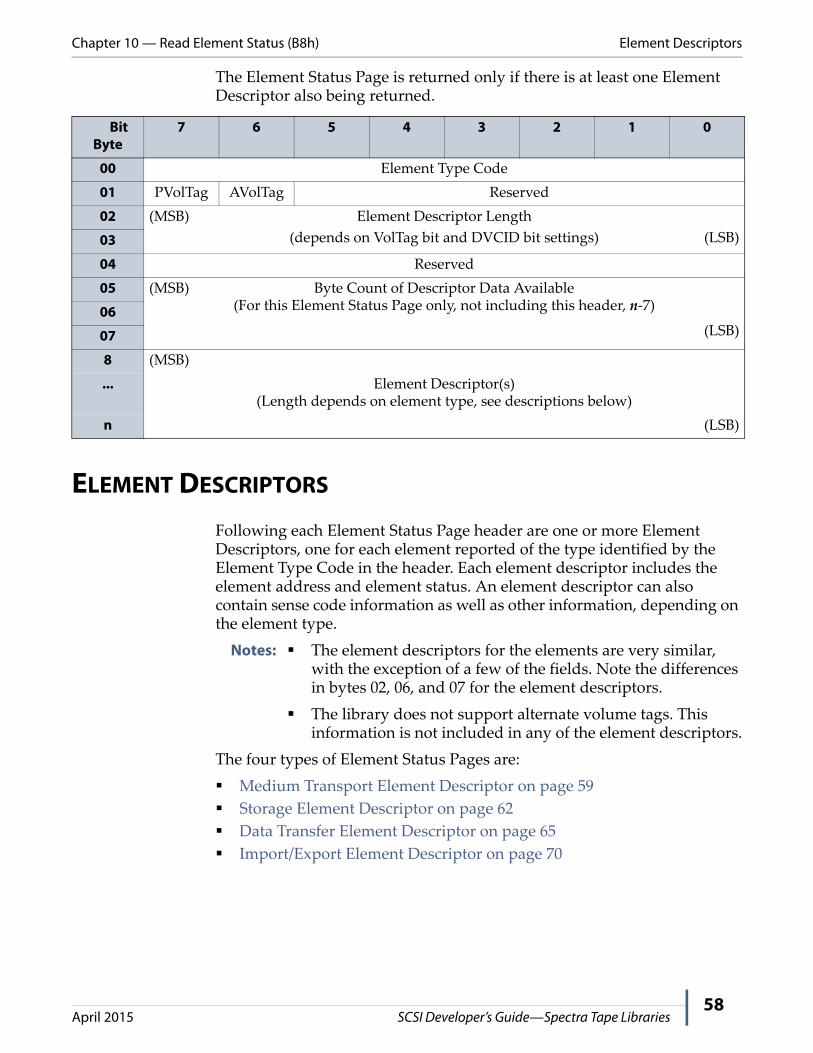
Chapter 10 — Read Element Status (B8h) Element Descriptors
April 2015 SCSI Developer’s Guide—Spectra Tape Libraries58
The Element Status Page is returned only if there is at least one Element Descriptor also being returned.
ELEMENT DESCRIPTORS
Following each Element Status Page header are one or more Element Descriptors, one for each element reported of the type identified by the Element Type Code in the header. Each element descriptor includes the element address and element status. An element descriptor can also contain sense code information as well as other information, depending on the element type.
Notes: The element descriptors for the elements are very similar, with the exception of a few of the fields. Note the differences in bytes 02, 06, and 07 for the element descriptors.
The library does not support alternate volume tags. This information is not included in any of the element descriptors.
The four types of Element Status Pages are:
Medium Transport Element Descriptor on page 59
Storage Element Descriptor on page 62
Data Transfer Element Descriptor on page 65
Import/Export Element Descriptor on page 70
BitByte
7 6 5 4 3 2 1 0
00 Element Type Code
01 PVolTag AVolTag Reserved
02 (MSB) Element Descriptor Length
(depends on VolTag bit and DVCID bit settings) (LSB)03
04 Reserved
05 (MSB) Byte Count of Descriptor Data Available(For this Element Status Page only, not including this header, n‐7)
(LSB)
06
07
8 (MSB)
... Element Descriptor(s)(Length depends on element type, see descriptions below)
n (LSB)

Chapter 10 — Read Element Status (B8h) Element Descriptors
April 2015 SCSI Developer’s Guide—Spectra Tape Libraries59
Medium Transport Element Descriptor
The medium transport element is the transporter (robot). The library contains one medium transport element (even if it contains two robots), for which it returns the following medium transport element descriptor.
BitByte
7 6 5 4 3 2 1 0
00 (MSB) Element Address
(LSB)01
02 Reserved Except Reserved Full
03 Reserved
04 Additional Sense Code
05 Additional Sense Code Qualifier
06 Reserved
07
08
09 SValid Invert Reserved
10 (MSB) Source Storage Element Address
(LSB)11
12 Primary Volume Tag Information(field omitted if PVolTag = 0)...
47
48 Reserved(field moved up if PVolTag = 0)...
51
52 Media Domain(field moved up if PVolTag = 0)
(field omitted if Include tape generation in Read Element Status is not selected on the BlueScale Advanced Partition Setting screen)
53 Media Type(field moved up if PVolTag = 0)
(field omitted if Include tape generation in Read Element Status is not selected on the BlueScale Advanced Partition Setting screen)
54 to 55 Reserved (00h, 00h)
(field omitted if PVolTag = 0)

Chapter 10 — Read Element Status (B8h) Element Descriptors
April 2015 SCSI Developer’s Guide—Spectra Tape Libraries60
Table 10-3: Parameter values returned in the Medium Transport Element descriptor
Field Name Value Returned
Meaning
Element Address Varies Shows the current element address of the medium transport element (the transporter). The default element address is 00 01h.
Except 0 Indicates that the medium transport element is in some sort of abnormal state. More information on the nature of the exception is available in the ASC and ASCQ fields.
1 Indicates that the medium transport element is in a normal state.
Full 0 Indicates that the medium transport element does not contain media.
1 Indicates that the medium transport element contains media.
Additional Sense Code (ASC)
Varies The ASC and ASCQ together may provide more information about the condition that caused the Except bit to be set to 1.
Their meaning here is the same as the ASC and ASCQ returned to the REQUEST SENSE command. See Appendix A – Error Reporting, beginning on page 96 for information about the meanings of all ASC/ASCQ combinations.
Additional Sense Code Qualifier (ASCQ)
Varies
SValid (Source Valid)
0 Indicates that the value in the Source Storage Element Address field is not valid.
1 Indicates that the value in the Source Storage Element Address
field is valid.
Invert 0 The Spectra Tape Libraries do not support two‐sided media and do not invert the media. This bit is always 0.
Source Storage Element Address
Varies Shows the address of the last element from which the media was moved.
Primary Volume Tag Information
Varies a If the PVolTag bit in the data header is 1, this field contains the ASCII representation of the barcode label (volume tag) information for the media occupying this element.
If the PVolTag bit is 0, this field is omitted entirely.
Note: There is rarely a barcode associated with the medium transport element.
Media Domain b
Note: This field is not valid if the Full bit is not set.
43h Indicates that the element contains a cleaning cartridge.
4Ch Indicates that the element contains an LTO cartridge.
4Ah Indicates that the element contains a TS11x0 technology cartridge.
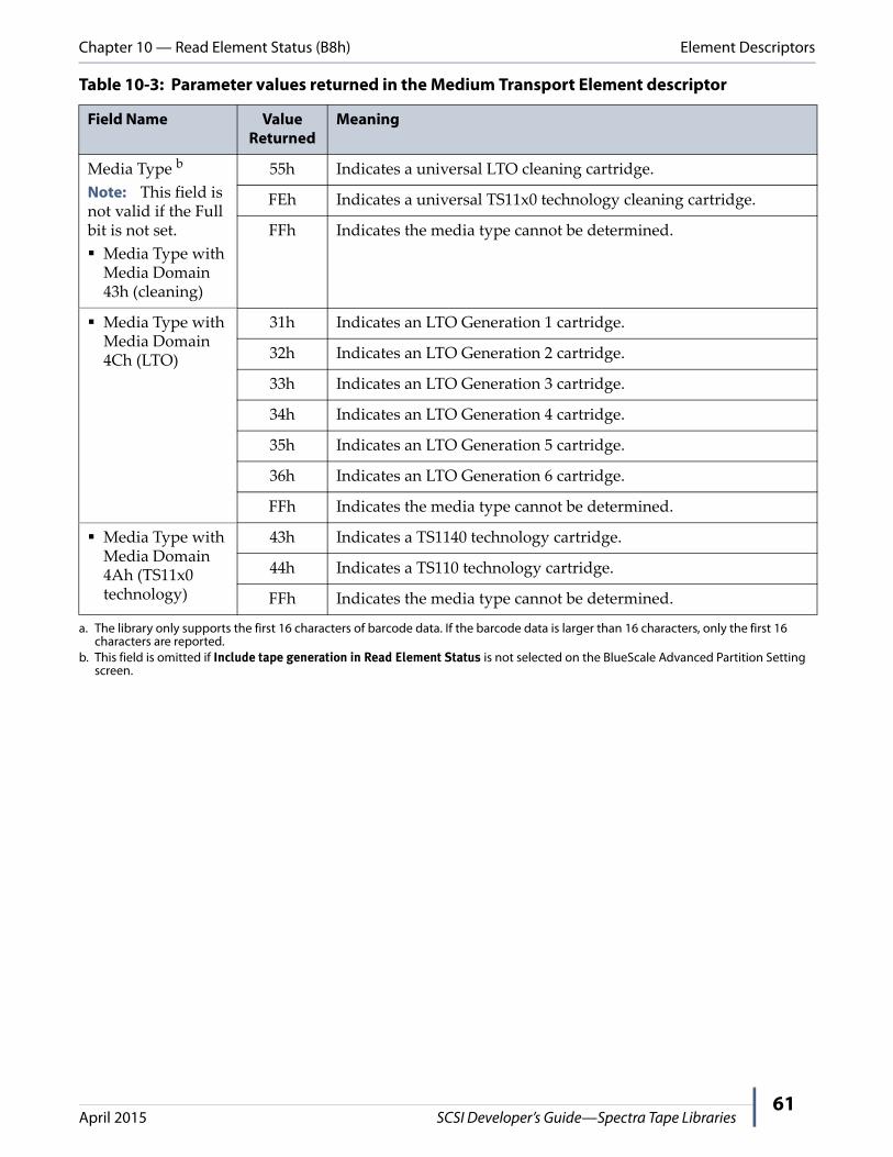
Chapter 10 — Read Element Status (B8h) Element Descriptors
April 2015 SCSI Developer’s Guide—Spectra Tape Libraries61
Media Type b
Note: This field is not valid if the Full bit is not set.
Media Type with Media Domain 43h (cleaning)
55h Indicates a universal LTO cleaning cartridge.
FEh Indicates a universal TS11x0 technology cleaning cartridge.
FFh Indicates the media type cannot be determined.
Media Type with Media Domain 4Ch (LTO)
31h Indicates an LTO Generation 1 cartridge.
32h Indicates an LTO Generation 2 cartridge.
33h Indicates an LTO Generation 3 cartridge.
34h Indicates an LTO Generation 4 cartridge.
35h Indicates an LTO Generation 5 cartridge.
36h Indicates an LTO Generation 6 cartridge.
FFh Indicates the media type cannot be determined.
Media Type with Media Domain 4Ah (TS11x0 technology)
43h Indicates a TS1140 technology cartridge.
44h Indicates a TS110 technology cartridge.
FFh Indicates the media type cannot be determined.
a. The library only supports the first 16 characters of barcode data. If the barcode data is larger than 16 characters, only the first 16 characters are reported.
b. This field is omitted if Include tape generation in Read Element Status is not selected on the BlueScale Advanced Partition Setting screen.
Table 10-3: Parameter values returned in the Medium Transport Element descriptor
Field Name Value Returned
Meaning

Chapter 10 — Read Element Status (B8h) Element Descriptors
April 2015 SCSI Developer’s Guide—Spectra Tape Libraries62
Storage Element Descriptor
Each magazine slot in the library is a storage element. For each storage element, the library returns the following storage element descriptor.
BitByte
7 6 5 4 3 2 1 0
00 (MSB) Element Address
(LSB)01
02 Reserved Access Except RSVD Full
03 Reserved
04 Additional Sense Code
05 Additional Sense Code Qualifier
06 Reserved
07
08
09 SValid Invert Reserved
10 (MSB) Source Storage Element Address
(LSB)11
12 Primary Volume Tag Information(field omitted if PVolTag = 0)...
47
48 Reserved(field moved up if PVolTag = 0)...
51
52 Media Domain (field moved up if PVolTag = 0)(field omitted if Include tape generation in Read Element Status is not selected on the
BlueScale Advanced Partition Setting screen)
53 Media Type (field moved up if PVolTag = 0)(field omitted if Include tape generation in Read Element Status is not selected on the
BlueScale Advanced Partition Setting screen)
54 to 55 Reserved (00h, 00h)
(field omitted if PVolTag = 0)

Chapter 10 — Read Element Status (B8h) Element Descriptors
April 2015 SCSI Developer’s Guide—Spectra Tape Libraries63
Table 10-4: Parameter values for the Storage Element descriptor
Field Name Value Returned
Meaning
Element Address Varies a Shows the address of the storage location (the cartridge slot).
Access 0 Indicates that the medium transport element cannot access the media at the storage location. This is possible when there is not a magazine in the specified location or the slot is reserved by the front panel. If the slot is reserved by the front panel, the Except bit will be set and the ASC and ASCQ values will be set to 80h, 18h.
1 Indicates that the medium transport element can access the media at the storage location.
Except 0 Indicates that the storage element is in a normal state. Any data in the Additional Sense Code and Additional Sense Code Qualifier fields is invalid.
1 Indicates that the storage element is in some sort of abnormal state or the element is reserved by the front panel for queued ejects. See Overview of T120 and T50e Entry/Exit Modes on page 73 for a description of queued ejects. More information on the nature of the exception is available in the Additional Sense Code and Additional Sense Code Qualifier fields.
Full 0 Indicates that the storage element does not contain media.
1 Indicates that the storage element contains media.
Additional Sense Code (ASC)
Varies The ASC and ASCQ together may provide more information about the condition which caused the Except bit to be set to 1. Their meaning here is the same as the ASC and ASCQ returned to the REQUEST SENSE command. For a listing of the meanings of all ASC‐ASCQ combinations, see Appendix A – Error Reporting, beginning on page 96.
Additional Sense Code Qualifier (ASCQ)
Varies
SValid (Source Valid)
0 Indicates that the value in the Source Storage Element Address field is not valid.
1 Indicates that the value in the Source Storage Element Address field is valid.
Invert 0 The tape libraries do not support two‐sided media and do not invert the media. This bit is always 0.
Source Storage Element Address
Varies a Shows the storage element address where the media was previously located.
Primary Volume Tag Information
Varies b If the PVolTag bit in the data header is 1, this field contains the barcode label (volume tag) information for the media occupying this location.
If the PVolTag bit is 0, this field is omitted entirely.

Chapter 10 — Read Element Status (B8h) Element Descriptors
April 2015 SCSI Developer’s Guide—Spectra Tape Libraries64
Media Domain c
Note: This field is not valid if the Full bit is not set.
43h Indicates that the element contains a cleaning cartridge.
4Ch Indicates that the element contains an LTO cartridge.
4Ah Indicates that the element contains a TS11x0 technology cartridge.
Media Type c
Note: This field is not valid if the Full bit is not set.
Media Type with Media Domain 43h (cleaning)
55h Indicates a universal LTO cleaning cartridge.
FEh Indicates a universal TS11x0 technology cleaning cartridge.
FFh Indicates the media type cannot be determined.
Media Type with Media Domain 4Ch (LTO)
31h Indicates an LTO Generation 1 cartridge.
32h Indicates an LTO Generation 2 cartridge.
33h Indicates an LTO Generation 3 cartridge.
34h Indicates an LTO Generation 4 cartridge.
35h Indicates an LTO Generation 5 cartridge.
36h Indicates an LTO Generation 6 cartridge.
FFh Indicates the media type cannot be determined.
Media Type with Media Domain 4Ah (TS11x0 technology)
43h Indicates a TS1140 technology cartridge.
44h Indicates a TS1150 technology cartridge.
FFh Indicates the media type cannot be determined.
a. The Range of Values is supported by the MODE SELECT command.b. The library only supports the first 16 characters of barcode data. If the barcode is larger than 16 characters, only the first 16 characters
are reported.c. This field is omitted if Include tape generation in Read Element Status is not selected on the BlueScale Advanced Partition Setting
screen.
Table 10-4: Parameter values for the Storage Element descriptor
Field Name Value Returned
Meaning

Chapter 10 — Read Element Status (B8h) Element Descriptors
April 2015 SCSI Developer’s Guide—Spectra Tape Libraries65
Data Transfer Element Descriptor
The descriptor returned depends on whether DVCID is 0 or 1. For DVCID = 0, the library returns the following data transfer element descriptor for each drive installed.
BitByte
7 6 5 4 3 2 1 0
00 (MSB) Element Address
(LSB)01
02 Reserved Access Except Reserved Full
03 Reserved
04 Additional Sense Code
05 Additional Sense Code Qualifier
06 Obsolete Reserved Obsolete Obsolete Reserved Obsolete
07 Obsolete
08 Reserved
09 SValid Invert Reserved
10 (MSB) Source Storage Element Address
(LSB)11
12 Primary Volume Tag Information(omitted if PVolTag = 0)...
47
48 Reserved(field moved up if PVolTag = 0)...
51
52 Media Domain (field moved up if PVolTag = 0)(field omitted if Include tape generation in Read Element Status is not selected on the
BlueScale Advanced Partition Setting screen)
53 Media Type (field moved up if PVolTag = 0)(field omitted if Include tape generation in Read Element Status is not selected on the
BlueScale Advanced Partition Setting screen)
54 Drive Domain (field moved up if PVolTag = 0)(field omitted if Include tape generation in Read Element Status is not selected on the
BlueScale Advanced Partition Setting screen)
55 Drive Type (field moved up if PVolTag = 0)(field omitted if Include tape generation in Read Element Status is not selected on the
BlueScale Advanced Partition Setting screen)

Chapter 10 — Read Element Status (B8h) Element Descriptors
April 2015 SCSI Developer’s Guide—Spectra Tape Libraries66
For DVCID = 1, the library returns the following data transfer element descriptor for each drive installed.
BitByte
7 6 5 4 3 2 1 0
00 (MSB) Element Address
(LSB)01
02 Reserved Access Except Reserved Full
03 Reserved
04 Additional Sense Code
05 Additional Sense Code Qualifier
06 Obsolete Reserved Obsolete Obsolete Reserved Obsolete
07 Obsolete
08 Reserved
09 SValid Invert Reserved
10 (MSB) Source Storage Element Address
(LSB)11
12 Primary Volume Tag Information(omitted if PVolTag = 0)...
47
48 Reserved Code Set (field moved up if PVolTag = 0)
49 Reserved Identifier Type (field moved up if PVolTag=0)
50 Reserved (field moved up if PVolTag = 0)
51 Identifier Length (1Eh) (field moved up if PVolTag = 0)
52 (MSB) Device Identifier (field moved up if PVolTag = 0)
(LSB)
...
83
84 Media Domain (field moved up if PVolTag = 0)(field omitted if Include tape generation in Read Element Status is not selected on the
BlueScale Advanced Partition Setting screen)
85 Media Type (field moved up if PVolTag = 0)(field omitted if Include tape generation in Read Element Status is not selected on the
BlueScale Advanced Partition Setting screen)
86 Drive Domain (field moved up if PVolTag = 0)(field omitted if Include tape generation in Read Element Status is not selected on the
BlueScale Advanced Partition Setting screen)
87 Drive Type (field moved up if PVolTag = 0)(field omitted if Include tape generation in Read Element Status is not selected on the
BlueScale Advanced Partition Setting screen)

Chapter 10 — Read Element Status (B8h) Element Descriptors
April 2015 SCSI Developer’s Guide—Spectra Tape Libraries67
Table 10-5: Parameter values for the Data Transfer Element descriptor
Field Name Value Returned
Meaning
Element Address Varies a Shows the address for the data transfer element (drive).
Access 0 Indicates that the medium transport element cannot access the drive.
1 Indicates that the medium transport element can access the drive.
Except 0 Indicates that the drive is in a normal state. Any data in the Additional Sense Code and Additional Sense Code Qualifier fields is invalid.
1 Indicates that the drive is in some sort of abnormal state. More information on the nature of the exception is available in the Additional Sense Code and Additional Sense Code Qualifier fields.
Full 0 Indicates that the drive does not contain media.
1 Indicates that the drive contains media.
ASC Varies The ASC and ASCQ together may provide more information about the condition which caused the Except bit to be set to 1.
Their meaning here is the same as the ASC and ASCQ returned to the REQUEST SENSE command. For a listing of the meanings of all ASC‐ASCQ combinations, see Appendix A – Error Reporting, beginning on page 96.
ASCQ
SValid (Source Valid)
0 Indicates that the value in the Source Storage Element Address field is not valid.
1 Indicates that the value in the Source Storage Element Address field is valid.
Invert 0 The tape libraries do not support two‐sided media and do not invert the media. This bit is always 0.
Source Storage Element Address
Varies a Shows the storage element address from which the media was moved.
Primary Volume Tag Information
Varies b If the PVolTag bit in the data header is 1, this field contains the barcode label (volume tag) information for the media occupying this drive.
If the PVolTag bit is 0, this field is omitted entirely.
CodeSet 0 When the DVCID = 0, the Identifier field is not valid.
2 When DVCID = 1 and CodeSet = 2, the Identifier field (bytes 52 through 83) contains ASCII data.
Identifier Type 1 Indicates that it is a SCSI parallel interface which in this case is the drive serial number.

Chapter 10 — Read Element Status (B8h) Element Descriptors
April 2015 SCSI Developer’s Guide—Spectra Tape Libraries68
Identifier Length c 00h The drive identifier is omitted.
1Gh The drive identifier is 32 bytes in length.
Device Identifier Varies c The 32 byte null terminated ASCII representation of the drive serial number.
Media Domain d
Note: This field is not valid if the Full bit is not set.
43h Indicates that the element contains a cleaning cartridge.
4Ch Indicates that the element contains an LTO cartridge.
4Ah Indicates that the element contains a TS11x0 technology cartridge.
Media Type d
Note: This field is not valid if the Full bit is not set.
Media Type with Media Domain 43h (cleaning)
55h Indicates a universal LTO cleaning cartridge.
FEh Indicates a universal TS11x0 technology cleaning cartridge.
FFh Indicates the media type cannot be determined.
Media Type with Media Domain 4Ch (LTO)
31h Indicates an LTO Generation 1 cartridge.
32h Indicates an LTO Generation 2 cartridge.
33h Indicates an LTO Generation 3 cartridge.
34h Indicates an LTO Generation 4 cartridge.
35h Indicates an LTO Generation 5 cartridge.
36h Indicates an LTO Generation 6 cartridge.
FFh Indicates the media type cannot be determined.
Media Type with Media Domain 4Ah (TS11x0 technology)
43h Indicates a TS1140 technology cartridge.
44h Indicates a TS1150 technology cartridge.
FFh Indicates the media type cannot be determined.
Drive Domain d
Note: This field is not valid if the Full bit is not set.
4Ch Indicates that the element contains an LTO drive.
4Ah Indicates that the element contains a TS11x0 technology drive.
Table 10-5: Parameter values for the Data Transfer Element descriptor
Field Name Value Returned
Meaning

Chapter 10 — Read Element Status (B8h) Element Descriptors
April 2015 SCSI Developer’s Guide—Spectra Tape Libraries69
Drive Type d
Note: This field is not valid if the Full bit is not set.
Drive Type with Drive Domain 4Ch (LTO)
31h Indicates an IBM LTO Generation 1 drive.
33h Indicates an HP LTO Generation 2 drive.
34h Indicates an IBM LTO Generation 2 drive.
36h Indicates an HP LTO Generation 3 drive.
37h Indicates an IBM LTO Generation 3 drive.
3Ah Indicates an IBM LTO Generation 4 drive.
3Ch Indicates an IBM LTO Generation 5 drive.
3Eh Indicates an IBM LTO Generation 6 drive.
FFh Indicates the drive type cannot be determined.
Drive Type with Drive Domain 4Ah (TS11x0 technology)
43h Indicates a TS1140 technology drive.
44h Indicates a TS1150 technology drive.
FFh Indicates the drive type cannot be determined.
a. Refer to Chapter 5 – Mode Select (15h), beginning on page 29 for information about the valid values for the element addresses.b. The library only supports the first 16 characters of barcode data. If the barcode data is longer than 16 characters, only the first
16 characters are reported.c. The identifier is omitted if DVCID (in the Read Element Status CDB) was set to 0 (as is shown by the 00h return for Identifier Length).d. This field is omitted if Include tape generation in Read Element Status is not selected on the BlueScale Advanced Partition Setting
screen.
Table 10-5: Parameter values for the Data Transfer Element descriptor
Field Name Value Returned
Meaning
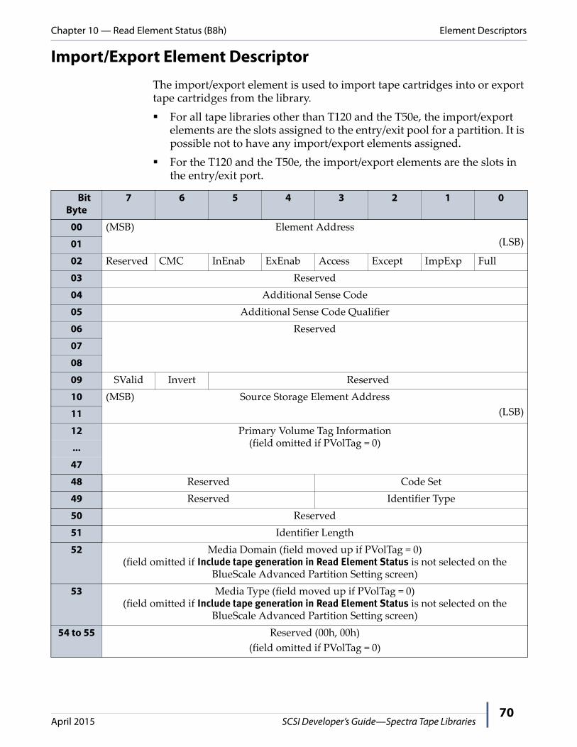
Chapter 10 — Read Element Status (B8h) Element Descriptors
April 2015 SCSI Developer’s Guide—Spectra Tape Libraries70
Import/Export Element Descriptor
The import/export element is used to import tape cartridges into or export tape cartridges from the library.
For all tape libraries other than T120 and the T50e, the import/export elements are the slots assigned to the entry/exit pool for a partition. It is possible not to have any import/export elements assigned.
For the T120 and the T50e, the import/export elements are the slots in the entry/exit port.
BitByte
7 6 5 4 3 2 1 0
00 (MSB) Element Address
(LSB)01
02 Reserved CMC InEnab ExEnab Access Except ImpExp Full
03 Reserved
04 Additional Sense Code
05 Additional Sense Code Qualifier
06 Reserved
07
08
09 SValid Invert Reserved
10 (MSB) Source Storage Element Address
(LSB)11
12 Primary Volume Tag Information(field omitted if PVolTag = 0)...
47
48 Reserved Code Set
49 Reserved Identifier Type
50 Reserved
51 Identifier Length
52 Media Domain (field moved up if PVolTag = 0)(field omitted if Include tape generation in Read Element Status is not selected on the
BlueScale Advanced Partition Setting screen)
53 Media Type (field moved up if PVolTag = 0)(field omitted if Include tape generation in Read Element Status is not selected on the
BlueScale Advanced Partition Setting screen)
54 to 55 Reserved (00h, 00h)
(field omitted if PVolTag = 0)
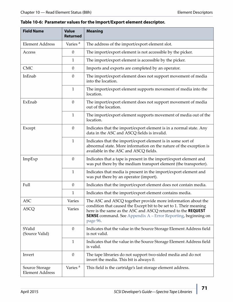
Chapter 10 — Read Element Status (B8h) Element Descriptors
April 2015 SCSI Developer’s Guide—Spectra Tape Libraries71
Table 10-6: Parameter values for the Import/Export element descriptor.
Field Name Value Returned
Meaning
Element Address Varies a The address of the import/export element slot.
Access 0 The import/export element is not accessible by the picker.
1 The import/export element is accessible by the picker.
CMC 0 Imports and exports are completed by an operator.
InEnab 0 The import/export element does not support movement of media into the location.
1 The import/export element supports movement of media into the location.
ExEnab 0 The import/export element does not support movement of media out of the location.
1 The import/export element supports movement of media out of the location.
Except 0 Indicates that the import/export element is in a normal state. Any data in the ASC and ASCQ fields is invalid.
1 Indicates that the import/export element is in some sort of abnormal state. More information on the nature of the exception is available in the ASC and ASCQ fields.
ImpExp 0 Indicates that a tape is present in the import/export element and was put there by the medium transport element (the transporter).
1 Indicates that media is present in the import/export element and was put there by an operator (import).
Full 0 Indicates that the import/export element does not contain media.
1 Indicates that the import/export element contains media.
ASC Varies The ASC and ASCQ together provide more information about the condition that caused the Except bit to be set to 1. Their meaning here is the same as the ASC and ASCQ returned to the REQUEST SENSE command. See Appendix A – Error Reporting, beginning on page 96.
ASCQ Varies
SValid (Source Valid)
0 Indicates that the value in the Source Storage Element Address field is not valid.
1 Indicates that the value in the Source Storage Element Address field is valid.
Invert 0 The tape libraries do not support two‐sided media and do not invert the media. This bit is always 0.
Source Storage Element Address
Varies a This field is the cartridge’s last storage element address.

Chapter 10 — Read Element Status (B8h) Element Descriptors
April 2015 SCSI Developer’s Guide—Spectra Tape Libraries72
Primary Volume Tag Information
Varies b If the PVolTag bit in the data header is 1, this field contains the barcode label (volume tag) information for the media occupying this drive.
If the PVolTag bit is 0, this field is omitted entirely.
CodeSet 0 The Identifier fields are not valid.
Identifier Length 0 No Identifier is returned.
Media Domain c
Note: This field is not valid if the Full bit is not set.
43h Indicates that the element contains a cleaning cartridge.
4Ch Indicates that the element contains an LTO cartridge.
4Ah Indicates that the element contains a TS11x0 technology cartridge.
Media Type c
Note: This field is not valid if the Full bit is not set.
Media Type with Media Domain 43h (cleaning)
55h Indicates a universal LTO cleaning cartridge.
FEh Indicates a universal TS11x0 technology cleaning cartridge.
FFh Indicates the media type cannot be determined.
Media Type with Media Domain 4Ch (LTO)
31h Indicates an LTO Generation 1 cartridge.
32h Indicates an LTO Generation 2 cartridge.
33h Indicates an LTO Generation 3 cartridge.
34h Indicates an LTO Generation 4 cartridge.
35h Indicates an LTO Generation 5 cartridge.
36h Indicates an LTO Generation 6 cartridge.
FFh Indicates the media type cannot be determined.
Media Type with Media Domain 4Ah (TS11x0 technology)
43h Indicates a TS1140 technology cartridge.
44h Indicates a TS1150 technology cartridge.
FFh Indicates the media type cannot be determined.
a. See Chapter 6 – Mode Sense (1Ah), beginning on page 36 for range of values supported for element addresses.b. The library only supports the first 16 characters of barcode data. If the barcode data is longer than 16 characters, only the first
16 characters are reported.c. This field is omitted if Include tape generation in Read Element Status is not selected on the BlueScale Advanced Partition Setting
screen.
Table 10-6: Parameter values for the Import/Export element descriptor.
Field Name Value Returned
Meaning

Chapter 10 — Read Element Status (B8h) Element Descriptors
April 2015 SCSI Developer’s Guide—Spectra Tape Libraries73
Overview of T120 and T50e Entry/Exit ModesThe Entry/Exit mode determines how the Entry/Exit port (E/E port) operates. Entry/Exit modes are only applicable to the T120 and T50e libraries. The T120 supports Standard, Queued Eject, and Shared modes; while the T50e only supports the Standard and Queued Eject modes.
For additional information about the Entry/Exit modes, log on to the Support portal at http://support.spectralogic.com and read Knowledge Base article 469.
Standard Mode. When the Entry/Exit port is set to Standard mode, a single data partition “owns” the Entry/Exit port; additional data partitions cannot be configured. Both the T120 and the T50e support Standard mode. In Standard mode, the library’s response to a READ ELEMENT STATUS command from the backup software indicates that it has eight slots (for a T120) or one slot (for a T50e) in the E/E port and that all of the slots are import‐enabled, export‐enabled, and accessible.
The Full bit is set as appropriate, to indicate whether each slot has a cartridge in it. The backup software has full import/export access to these slots at any time. All moves are physical moves to and from the E/E port slots, so the number of cartridges that can be imported or exported by the software is limited by the physical capacity of the E/E port.
E/E Slot Import-Enabled Bit (InEnab)
Export-Enabled Bit (ExEnab)
Access Bit Full Bit
1 Always set(allows use for tape
imports)
Always set(allows use for tape
exports)
Is set (allows access by the
backup software) if the E/E port is
closed and cleared when the E/E port is open
Is set if a slot contains a tape, and cleared if a slot does not contain a tape
2
3
4
5
6
7
8

Chapter 10 — Read Element Status (B8h) Element Descriptors
April 2015 SCSI Developer’s Guide—Spectra Tape Libraries74
Shared Mode (T120 only). When the library is set to Shared mode, it allows two or more partitions in the library to share the E/E port. The library’s response to a READ ELEMENT STATUS command from the backup software indicates that it has nine slots in the E/E port:
Slots 1 through 8 correspond to the physical slots in the E/E port and are import‐only (the Import Enabled bit is set, but the Export Enabled bit is not). In addition, the slots have the Access bit cleared (access not allowed) until an import operation is initiated from the front panel of the library. When a front panel import operation is initiated for a partition, the Access bit for that partition is set, which enables access to the E/E port for import operations. The backup software can then use the E/E port to import cartridges into the partition.
Note: The Access bit is only set for the partition for which the import operation is requested. The E/E port remains inaccessible for any other partitions configured in the library.
In addition to the eight physical slots, the E/E port has an additional virtual slot (Slot 9), which is export‐only (the Export Enabled bit is set, but the Import Enabled bit is not). For E/E Slot 9, the Access bit is always set, and the Full bit is always cleared. As a result, the response to an READ ELEMENT STATUS command indicates that Slot 9 is always empty and available for export operations.
When the backup software exports a cartridge, the cartridge remains in its current storage slot. No physical move occurs, although the library reports that the move is complete. The Exception bit for the slot where the cartridge is located is set to indicate that the slot is in an “abnormal” state. Because the virtual export slot (Slot 9) never contains a cartridge, the library continues to report that the slot is empty and available for use, regardless of the number of cartridges that are exported using this method.
E/E Slot Import-Enabled Bit (InEnab)
Export-Enabled Bit (ExEnab)
Access Bit Full Bit
1 Always set(allows use for tape
imports)
Always cleared(exports to this slot are not allowed)
Is set ONLY for the selected
partition during import operations when the E/E port
is closed
Is set if a slot contains a tape, and cleared if a slot does not contain a tape
2
3
4
5
6
7
8
9 Always cleared(imports from this slot
are not allowed)
Always set(allows use for tape
exports)
Always set(allow access by
the backup software)
Always cleared(the slot always appears empty)
Chapter 10 — Read Element Status (B8h) Element Descriptors
April 2015 SCSI Developer’s Guide—Spectra Tape Libraries75
When an Eject Queued Tapes operation is requested from the front panel, the exported cartridges are physically moved to the eight slots in the E/E port so that they can be removed from the library. After the cartridges are removed, all of the Exception bits that were set for the storage slots are cleared and the Access bits are set, making those slots once again accessible to the backup software.
If the library is powered on with cartridges already in the E/E port, the cartridges are initially accessible by any partition (because the library does not know which partition should “own” them). In this case, selecting a partition and opening/closing the E/E port makes the cartridges accessible to the selected partition, just as with any import operation. A partition also gains ownership of the E/E port when you use the front panel to move cartridges to or from the E/E port.
Queued Eject Mode. Queued Ejects allow two or more partitions in the library to share the E/E port. Access to certain tapes and slots may be restricted and imports/exports may not be handled the way you may expect. Both the T120 and the T50e support Queued Eject mode. When the Entry/Exit port is set to Queued Eject mode, the libraryʹs response to a READ ELEMENT STATUS command from the backup software indicates that it has only one export‐only E/E slot.
The single E/E slot is functionally identical to the virtual E/E slot in Shared mode. As with Shared mode, the Exception bit is set and the Access bit cleared for any storage slots that contain cartridges that have been exported.
The BlueScale software treats all eject operations initiated by the backup software as logical moves to the E/E slot. The move is reported as successful, but the ejected cartridge is left in its original slot. The Exception bit for the slot is set for the storage slot and the Access bit for the slot is cleared, making the storage slot inaccessible to the backup software.
When an Eject Queued Tapes operation is requested from the front panel, the exported cartridges are physically moved to the single slot in a T50e or the eight slots in a T120 E/E port so that they can be removed from the library. After the cartridges are removed, all of the Exception bits that were set for the storage slots are cleared and the Access bits are set, making those slots once again accessible to the backup software.
E/E Slot Import-Enabled Bit (InEnab)
Export-Enabled Bit (ExEnab)
Access Bit Full Bit
1 Always cleared (imports from this
slot are not allowed)
Always set (allows use for tape exports)
Always set(allows access by
the backup software)
Always cleared(the slot always appears empty)

Chapter 10 — Read Element Status (B8h) Element Descriptors
April 2015 SCSI Developer’s Guide—Spectra Tape Libraries76
Because the slot(s) in the E/E port are not import‐enabled, the only way to import cartridges into a partition is by using either a move queue or a bulk load command from the library front panel. This type of import operation does not automatically update the cartridge inventory maintained by the backup software. You must force the software to re‐inventory the partition after the import operation is complete to ensure that the inventory is accurate.
Command Status
The library returns a status byte after processing the READ ELEMENT STATUS command. This section describes when each type of status byte might be returned.
Good
The library returns Good status when it is able to process the command without errors.
Busy
Busy status indicates that the library is temporarily unable to accept a command from this initiator. The initiator may retry the command later.
Reservation Conflict
The library returns Reservation Conflict status when it is reserved by a different initiator. See Chapter 14 – Reserve (16h), beginning on page 88 for more information about the RESERVE command.
Check Condition
The library returns Check Condition status for the following reasons:
A Unit Attention condition is pending for the initiator.
A reserved bit is set to 1 in the CDB.
A parameter in the CDB is invalid (see Table 10‐7 for sense data).
Table 10-7: Invalid parameters in the READ ELEMENT STATUS CDB
Sense Key
ASC ASCQ SKSV Bit
C/D Bit
BPV Bit
Bit Pointer
Field Pointer
Error
5h 21h 01h 1 1 0 0 00 02h Invalid starting element address.
5h 24h 00h 1 1 1 — — A reserved bit is set in the CDB. The pointers indicate the bit in error.
5h 24h 00 1 1 1 3h 00 01h Invalid element type code.

77
CHAPTER 11Release (17h)
COMMAND DESCRIPTION
The RELEASE command enables the initiator to release reservations on the library or library elements that were set by the RESERVE (16h) command. For information on the RESERVE command, see Chapter 14 – Reserve (16h), beginning on page 88.
Only the initiator that reserved the library or its elements can release them. If another initiator attempts to release a reserved library or its elements, the library returns a Reservation Conflict status. Releasing an unreserved library or unreserved library elements is not an error.
BitByte
7 6 5 4 3 2 1 0
00 Operation Code (17h)
01 Obsolete a
a. These bits are ignored.
3rdPty Third Party Device ID Element
02 Reservation ID
03 Reserved
04
05 0 0 Reserved 0 0

Chapter 11 — Release (17h) What You Send to the Library
April 2015 SCSI Developer’s Guide—Spectra Tape Libraries78
WHAT YOU SEND TO THE LIBRARY
COMMAND STATUS
The library returns a status byte after processing the RELEASE command. This section describes when each type of status byte might be returned.
Good
The library returns Good status when it is able to process the command without errors.
Busy
Busy status indicates that the library is temporarily unable to accept a command from this initiator. The initiator may retry the command later.
Reservation Conflict
The library never returns Reservation Conflict status for the RELEASE command.
Table 11-1: RELEASE CDB field values
Field Name Values Allowed
Meaning
3rdPty 0 RELEASE is not being requested for a third‐party reservation.
1 RELEASE is being requested for a reservation made previously by this initiator for the third‐party device identified in the Third Party Device ID.
Third Party Device ID
0–7h Shows the SCSI ID of the third‐party device for which the library or some of its elements were previously reserved.
This field is ignored if the 3rdPty bit is 0.
Element 0 The library releases all active reservations, for the entire unit or any of its elements, which came from this initiator (or were for the third‐party device specified, if the 3rdPty bit is 1)
1 The library releases the element reserved for this initiator with the matching Reservation ID. See Chapter 14 – Reserve (16h), beginning on page 88 for information about assigning Reservation ID numbers using the RESERVE command.
Reservation ID Varies a
a. Any valid storage slot in the library reported by the MODE SENSE command. You cannot reserve an Import/Export, Medium Transport, or Data Transfer Element.
If the Element bit is 1, this field is checked to determine which elements to release. If the Element bit is 0, this field is ignored.

Chapter 11 — Release (17h) Command Status
April 2015 SCSI Developer’s Guide—Spectra Tape Libraries79
Check Condition
The library returns Check Condition status for the following reasons:
A Unit Attention condition is pending for the initiator.
A reserved bit is set to 1 in the CDB.
A parameter in the CDB is invalid (see Table 11‐2 for sense data).
Table 11-2: Invalid parameters in the RELEASE CDB
Sense Key
ASC ASCQ SKSV Bit
C/D Bit
BPV Bit
Bit Pointer
Field Pointer
Error
5h 24h 00h 1 1 1 — — A reserved bit is set in the CDB. The pointers indicate the bit in error.
5h 24h 00 1 1 1 1h 00 01h LongID field is set to 1.
5h 24h 00 1 1 1 1h 00 00h Element field is set to 1.

80
CHAPTER 12Report LUNs (A0h)
COMMAND DESCRIPTION (NOT SUPPORTED FOR PARALLEL SCSI LIBRARIES)
The REPORT LUNS command requests that the inventory of peripheral device logical units that are accessible to the initiator via the addressed SCSI target port be sent to the application client. The logical unit inventory is a list that includes the LUNs of all logical units having a Peripheral Qualifier value of 000b. Returning LUNs for logical units with Peripheral Qualifier values of 100b, 101b, 110b, or 111b is not supported.
The library supports a REPORT LUNS command when it is addressed to LUN zero. Support of the REPORT LUNS command by logical units other than logical unit zero is not supported.
Note: Devices compliant with SPC return a Check Condition status with sense key Illegal Request and additional sense data set to Invalid Field In CDB when the allocation length is less than 16 bytes.
The REPORT LUNS command returns Check Condition status only when the device server is unable to return the requested report of the logical unit inventory.
BitByte
7 6 5 4 3 2 1 0
00 Operation Code (A0h)
01 Reserved
...
05
06 (MSB) Allocation Length (LSB)
...
09
10 Reserved
11 Control
Chapter 12 — Report LUNs (A0h) Command Description (not supported for parallel SCSI libraries)
April 2015 SCSI Developer’s Guide—Spectra Tape Libraries81
If a REPORT LUNS command is received from an initiator with a pending Unit Attention condition (that is, before the device server reports Check Condition status), the device server performs the REPORT LUNS command.
If the Unit Attention condition was established because of a change in the logical unit inventory, that Unit Attention condition is cleared for that initiator by the REPORT LUNS command. Unit Attention conditions established for other reasons are not cleared by the REPORT LUNS command.
The REPORT LUNS data should be returned even though the device server is not ready for other commands. The default report of the logical unit inventory should be available without incurring any media access delays. The default report of the logical unit inventory contains at least LUN 0.
If the logical unit inventory changes for any reason, including completion of initialization, removal of a logical unit, or creation of a logical unit, the device server generates a unit attention command for all initiators.
The device server sets the additional sense code to Reported LUNs Data Has Changed. The execution of a REPORT LUNS command to any valid and installed logical unit clears the Unit Attention condition that has a sense code of Reported LUNs Data Has Changed for all logical units of that target with respect to the requesting initiator. A valid and installed logical unit is one having a peripheral qualifier of 000b in the standard INQUIRY data.

Chapter 12 — Report LUNs (A0h) What the Library Returns
April 2015 SCSI Developer’s Guide—Spectra Tape Libraries82
WHAT THE LIBRARY RETURNS
The LUN List Length field contains the length in bytes of the LUN list that is available to be transferred. The LUN list length is the number of logical unit numbers in the logical unit inventory multiplied by eight. If the allocation length in the CDB is too small to transfer information about the entire logical unit inventory, the LUN list length value is not adjusted to reflect the truncation.
Spectra Logic libraries always report the LUNs sequentially, as illustrated in the following table.
BitByte
7 6 5 4 3 2 1 0
00 Operation Code (A0h)
01 Reserved
02
03
04 (MSB) Allocation Length (LSB)
05
06
07 Reserved
LUN List
08...15
(MSB)
First LUN (00)
(LSB)
16...23
(MSB)
Second LUN (01)
(LSB)
N-7 (MSB) Last LUN (LSB)
N
Table 12-1: Examples of LUNs reported by a Spectra Logic library
LUNs Configuration 1 Configuration 2 Configuration 3 Configuration 4 Configuration 5
0 Drive 1 Library 1 Library 1 Library 1 Library 1
1 Drive 2 Drive 1 Drive 1 Drive 1 Library 2
2 Drive 3 Drive 2 Drive 2 Library 2
3 Drive 4 Drive 3 Library 2 Drive 1 (3)
4 Drive 4 Drive 1 (3)
5 Drive 2 (4)

Chapter 12 — Report LUNs (A0h) What the Library Returns
April 2015 SCSI Developer’s Guide—Spectra Tape Libraries83
Configuration 1 The QIP only has drives attached.
Configuration 2 The QIP is an exporting library QIP and has drives attached.
Configuration 3 and Configuration 4 The QIP is exporting two separate partitions (virtual libraries).
Configuration 5 The RIM is exporting two separate partitions (virtual libraries).
Command Status
The library returns a status byte after processing the REPORT LUNS command. This section describes when each type of status byte might be returned.
Good
The library returns Good status when it is able to process the command without errors.
Busy
Busy status indicates that the library is temporarily unable to accept a command from this initiator. The initiator may retry the command later.
Reservation Conflict
The library returns Reservation Conflict status when it is reserved by a different initiator. See Chapter 14 – Reserve (16h), beginning on page 88 for more information about the RESERVE command.
Check Condition
The library returns Check Condition status for the following reasons:
A reserved bit is set to 1 in the CDB.
A parameter in the CDB is invalid (see Table 12‐2 for sense data).
Table 12-2: Invalid parameters in the READ ELEMENT STATUS CDB
Sense Key
ASC ASCQ SKSV Bit
C/D Bit
BPV Bit
Bit Pointer
Field Pointer
Error
5h 24h 00h 1 1 1 — — A reserved bit is set in the CDB. The pointers indicate the bit in error.
5h 24h 00 1 1 1 3h 00 01h Invalid element type code.

84
CHAPTER 13Request Sense (03h)
COMMAND DESCRIPTION
The REQUEST SENSE command requests that the library transfer sense data to the initiator. It is generally issued immediately after the library reports a Check Condition status for the previous command.
WHAT YOU SEND TO THE LIBRARY
Allocation Length (byte 04) is the space allocated by the initiator for the sense data. The library returns a total of 52 bytes of sense data available to send. If you specify an Allocation Length greater than 52 bytes, the library sends 52. If you specify an Allocation Length less than 52 bytes, the library truncates the sense data at the specified Allocation Length.
BitByte
7 6 5 4 3 2 1 0
00 Operation Code (03h)
01 Obsolete a
a. These bits are ignored.
Reserved
02 Reserved
03
04 Allocation Length
05 0 0 Reserved 0 0

Chapter 13 — Request Sense (03h) Command Response
April 2015 SCSI Developer’s Guide—Spectra Tape Libraries85
COMMAND RESPONSE
The library returns the standard sense data, as described in the following table.
The sense data is valid for the Check Condition status just presented to the initiator. This sense data is preserved in the library for the initiator receiving the Check Condition status. Sense data is cleared when any subsequent command that is not a REQUEST SENSE or an INQUIRY (12h) command is received from the initiator.
BitByte
7 6 5 4 3 2 1 0
00 Valid Error code
01 Segment Number00h (not used)
02 Reserved for other device types Sense Key
03 (MSB) Information Bytes
(LSB)
...
06
07 Additional Sense Length = 2Ch
08 (MSB) Command Specific Information(not used)
(LSB)
...
11
12 Additional Sense Code (ASC)
13 Additional Sense Code Qualifier (ASCQ)
14 Field Replaceable Unit Code
15 SKSV (MSB)
16 Command Specific Information(not used)
(LSB)17
18 ASCII Representation of Sense Data(not used)...
51

Chapter 13 — Request Sense (03h) Command Response
April 2015 SCSI Developer’s Guide—Spectra Tape Libraries86
Refer to Appendix A – Error Reporting, beginning on page 96 for a list and description of sense codes.
Table 13-1: Field values for the data returned by the REQUEST SENSE command
Field Name Value Returned
Meaning
Valid 1b Indicates the sense data conforms to the SPC‐3 Standard.
Error Code 70h Indicates the sense data is for the current error. The library does not perform deferred error reporting (error code 71h).
Segment Number 00h This field is not implemented in the tape libraries.
Sense Key (General Error Category)
See Appendix A – Error Reporting, beginning on page 96 for more information.
0h No Sense. No specific sense information to report.
2h Not Ready. Indicates that the library cannot be accessed.
4h Hardware Error. The library detected a nonrecoverable hardware failure.
5h Illegal Request. There was an illegal parameter in the CDB or additional parameters supplied as data for some commands (for example, in MODE SELECT).
6h Unit Attention. The library’s condition has somehow changed. For example, media may have been moved, or the unit may have been reset.
9h Vendor‐unique. Sense information is specific to the tape libraries. The Additional Sense Code and Additional Sense Code Qualifier provide additional information.
Command Specific Information
0h This field is not implemented in the tape libraries.
Additional Sense Length
2Ch Indicates that 44 bytes (2Ch) of sense data follow this byte (52 total).
Additional Sense Code (ASC)
Varies Provide further information about the nature of the error condition, beyond that reported in the Sense Key field. See Appendix A – Error Reporting, beginning on page 96 for descriptions of all ASCs and ASCQs that the library supports and how to interpret the values returned.
Additional Sense Code Qualifier (ASCQ)
Varies
Field Replaceable Unit Code
00h No specific unit failure has been identified.
SKSV 0b Indicates the data in the Sense‐Key Specific field is not valid. No sense‐key specific information applies to the library.
ASCII Representation of Sense
Varies This field is not implemented in the Spectra tape libraries.

Chapter 13 — Request Sense (03h) Command Status
April 2015 SCSI Developer’s Guide—Spectra Tape Libraries87
COMMAND STATUS
The library returns a status byte after processing the REQUEST SENSE command. This section describes when each type of status byte might be returned.
Good
The library returns Good status when it is able to process the command without errors.
Busy
The library never returns Busy status for the REQUEST SENSE command.
Reservation Conflict
The library never returns Reservation Conflict status for the REQUEST SENSE command.
Check Condition
The library returns Check Condition status for the following reasons:
A reserved bit is set to 1 in the CDB.
A parameter in the CDB is invalid (see Table 13‐2 for sense data).
Table 13-2: Invalid parameters in the READ ELEMENT STATUS CDB
Sense Key
ASC ASCQ SKSV Bit
C/D Bit
BPV Bit
Bit Pointer
Field Pointer
Error
5h 24h 00h 1 1 1 — — A reserved bit is set in the CDB. The pointers indicate the bit in error.

88
CHAPTER 14Reserve (16h)
COMMAND DESCRIPTION
The RESERVE command allows the initiator to reserve the library (partition) as a whole. Reserving the library prevents another user from moving media to the import/export element of the library using the library’s touch screen control panel.
If the superseding reservation does not result in any reservation conflicts or error conditions, the library releases the previous reservation and completes the new reservations. A unit reservation of the library supersedes any previous element reservations by the same initiator.
The reserved library is released by issuing a RELEASE (17h) command from the same initiator, a bus device reset condition, a SCSI bus reset, or power‐cycling the library.
BitByte
7 6 5 4 3 2 1 0
00 Operation Code (16h)
01 Obsolete a
a. These bits are ignored.
Element
02 Reservation ID
03 (MSB) Element List Length
(LSB)04
05 Control

Chapter 14 — Reserve (16h) What You Send the Library
April 2015 SCSI Developer’s Guide—Spectra Tape Libraries89
WHAT YOU SEND THE LIBRARY
COMMAND STATUS
The library returns a status byte after processing the RESERVE command. This section describes when each type of status byte might be returned.
Good
The library returns Good status when it is able to process the command without errors.
Busy
Busy status indicates that the library is temporarily unable to accept a command from this initiator. The initiator may retry the command later.
Reservation Conflict
The library returns Reservation Conflict status when the library is reserved by a different initiator
Table 14-1: RESERVE CDB parameter values
Field Name Values Allowed
Meaning
Element 0 Requests reservation of entire library. If the library is reserved by another initiator, the library rejects this command with Reservation Conflict status.
Reservation ID 0 This field is only checked if the Element bit is set to 1. Because the Element bit is always set to 0, this field is ignored.
Element List Length
0 Because the library does not support reserving individual elements, the command is not followed by an element list.

Chapter 14 — Reserve (16h) Command Status
April 2015 SCSI Developer’s Guide—Spectra Tape Libraries90
Check Condition
The library returns Check Condition status for the following reasons:
A Unit Attention condition is pending for the initiator.
A reserved bit is set to 1 in the CDB.
A parameter in the CDB or element descriptor data is invalid (see Table 14‐2 for sense data).
Table 14-2: Invalid parameters in the RESERVE CDB and element descriptor data
Sense Key
ASC ASCQ SKSV Bit
C/D Bit
BPV Bit
Bit Pointer
Field Pointer
Error
5h 24h 00h 1 1 a — — The value for a field in the CDB is invalid. The pointers indicate the field in error.
a. Value depends on which bit is wrong.

91
CHAPTER 15Send Diagnostic (1Dh)
COMMAND DESCRIPTION
The SEND DIAGNOSTIC command causes the library to perform its diagnostic self‐tests or it causes the LCM to reset. Spectra tape libraries support the Default Self‐Test (SelfTest bit = 1 and Parameter List Length = 0) and Reset LCM (PF=1, SelfTest bit = 1, and Parameter List Length = 8).
If a self‐test or reset is successful, the library returns Good status; otherwise, it returns Check Condition status.
BitByte
7 6 5 4 3 2 1 0
00 Operation Code (1Dh)
01 Obsolete a
a. These bits are ignored.
PF Reserved SelfTest DevOfL UnitOfL
02 Reserved
03 (MSB) Parameter List Length (LSB)
04
05 0 0 Reserved 0 0
Chapter 15 — Send Diagnostic (1Dh) What You Send to the Library
April 2015 SCSI Developer’s Guide—Spectra Tape Libraries92
WHAT YOU SEND TO THE LIBRARY
Send Diagnostic Assignment Page (Page Code 80h)
Table 15-1: SEND DIAGNOSTIC CDB field values
Field Name Values Allowed
Meaning
PF (Page Format)
0 or 1 0 for library self‐test (SelfTest must be 1),
1 for LCM reset (SelfTest must be 0).
SelfTest 0 or 1 1 for library self‐test (PF must be 0)
0 for LCM reset (PF must be 1).
DevOfL (Device Off‐Line)
0 The library may not perform diagnostic tests whose results may be detected by subsequent I/O processes.
UnitOfL(Unit Off‐Line)
0 The library may not perform diagnostic tests that might affect the the positioning of media inside the library.
Parameter List Length
0 ‐ ffff Specifies the length (in bytes) of the list to be transferred to the library. A length of 0 indicates that no data is to be transferred. This is not considered an error. For the Reset LCM diagnostic the data out length should be 8. For the Default Self‐Test diagnostic this should be set to zero.
BitByte
7 6 5 4 3 2 1 0
00 Page Code (80h)
01 Reserved
02 (MSB) Page Length
(00 04h) (LSB)03
04 (MSB) Diagnostic ID
(00 01h) (LSB)05
06 (MSB) Reserved
(LSB)07
Table 15-2: Data sent on the Send Diagnostic Assignment page
Field Name Value Meaning
Page Code 08h Identifies the Send Diagnostic Assignment page.
Page Length 00 04h Indicates that there are an additional 4 bytes of element address data that follow this byte.
Diagnostic ID 00 01h Indicates the Reset LCM diagnostic.

Chapter 15 — Send Diagnostic (1Dh) Command Response
April 2015 SCSI Developer’s Guide—Spectra Tape Libraries93
COMMAND RESPONSE
Because the library only supports the default self‐test and LCM reset, there is no data returned from the SEND DIAGNOSTIC command. If the command is successful, a Good status is returned. Otherwise, a Check Condition status is returned. The sense information is available with a REQUEST SENSE command. Additional information may be returned in the ASC and ASCQ.
Check Condition
The library returns Check Condition status for the following reasons:
A Unit Attention condition is pending for the initiator.
A reserved bit is set to 1 in the CDB.
A parameter in the CDB or element descriptor data is invalid (see Table 15‐3 for sense data).
Table 15-3: Invalid parameters in the SEND DIAGNOSTIC CDB and element descriptor data
Sense Key
ASC ASCQ SKSV Bit
C/D Bit
BPV Bit
Bit Pointer
Field Pointer
Error
5h 24h 00h 1 1 a — — The value for a field in the CDB is invalid. The pointers indicate the field in error.
5h 26h 00h 1 0 0 0 b Invalid values in the Parameter List Header. All values must be 0. The value of the field pointer is the value of the first field that contains a non‐zero value (00, 01, 02, or 03).
Invalid Parameter Length.
Reserved bits set in the reserved fields 22 or 23 (bytes 18 or 19 of the Element Address Assignment page).
Storage element addresses are not consecutive.
Address wrap. Number of elements causes the address range to wrap back to 00 00.
5h 26h 00h 1 0 1 5h a Invalid Page Code.
5h 26h 00h 1 0 1 7h a Reserved bits set in the first byte of one of the MODE SELECT pages.
a. Value depends on which bit is wrong.b. Field pointer depends on the order in which the pages are sent.

94
CHAPTER 16Test Unit Ready (00h)
COMMAND DESCRIPTION
The TEST UNIT READY command lets the initiator determine whether the library is ready to accept all other valid commands, including motion commands. This is not a request for a library self‐test, which occurs at power‐on.
COMMAND STATUS
The library returns a status byte after processing the TEST UNIT READY command. This section describes when each type of status byte might be returned.
Good
The library returns Good status when it is able to process the command without errors. The library is ready to accept any valid command.
Busy
Busy status indicates that the library is temporarily unable to accept a command from this initiator. The initiator may retry the command later.
BitByte
7 6 5 4 3 2 1 0
00 Operation Code (00h)
01 Obsolete a
a. These bits are ignored.
Reserved
02 Reserved
...
04
05 0 0 Reserved 0 0

Chapter 16 — Test Unit Ready (00h) Command Status
April 2015 SCSI Developer’s Guide—Spectra Tape Libraries95
Reservation Conflict
The library returns Reservation Conflict status when it is reserved by a different initiator. See Chapter 14 – Reserve (16h), beginning on page 88 for more information about the RESERVE command.
Check Condition
The library returns Check Condition status for the following reasons:
A Unit Attention condition is pending for the initiator.
The library is not ready because it has just powered up, it received a bus device reset message, or after a power‐on reset. The sense key is set to Unit Attention (6h).
The library has experienced an unrecoverable hardware error.
A reserved bit is set to 1 in the CDB.
A parameter in the CDB or parameter list is invalid (see Table for sense data).
Table 16-1: Invalid parameters in the TEST UNIT READY CDB and parameter list
Sense Key
ASC ASCQ SKSV Bit
C/D Bit
BPV Bit
Bit Pointer
Field Pointer
Error
2h 04h 00h 0 0 0 0 0 Unit not ready, manual intervention required.
5h 24h 00h 1 1 1 — — A reserved bit is set in the CDB. The pointers indicate the bit in error.

96
APPENDIX AError Reporting
This appendix lists the Sense Keys, ASCs (Additional Sense Codes), and ASCQs (Additional Sense Code Qualifiers) for library errors. The ASCs and ASCQs are associated with the sense keys returned by the library in response to a REQUEST SENSE command (see Chapter 13 – Request Sense (03h), beginning on page 84). These three pieces of information combine to indicate a specific error condition.
Note: For error codes returned by tape drives (medium errors), refer to the tape drive manual for that specific drive type. See Related Publications on page 10.
SENSE KEYS
The following table describes the sense keys returned by the library. The sense key provides a general indication of the type of error that occurred.
Sense Key
Meaning Explanation
0h No Sense There is no specific sense key information.
2h Not Ready Library cannot be accessed. Operator intervention may be required to correct this condition. See the additional sense code description for more information.
4h Hardware Error
Library detected a non‐recoverable hardware failure while performing the command or during a self‐test. See the ASC description for more information.
5h Illegal Request Invalid command request received or the library is in the wrong mode to process the command.
6h Unit Attention Indicates that the data cartridge inventory may have been changed.
9h Vendor Specific Indicates vendor‐specific sense data for tape libraries.

Appendix A — Error Reporting Additional Sense Codes and Qualifiers
April 2015 SCSI Developer’s Guide—Spectra Tape Libraries97
Sense Keys Not Used
The libraries do not use the following sense keys:
ADDITIONAL SENSE CODES AND QUALIFIERS
Combining the Sense Key with the Additional Sense Code (ASC) and Additional Sense Code Qualifier (ASCQ) returned in response to a REQUEST SENSE command, provides the most complete error description available from the library. The following table describes the ASC/ASCQ associated with each sense key returned by the library. The error descriptions are listed in order by ASC and ASCQ for each of the sense keys.
Sense Key Meaning
1h Recovered Error
3h Medium Error
7h Data Protect
8h Blank Check
Ah Copy Aborted
Bh Aborted Command
Ch Equal
Dh Volume Overflow
Eh Miscompare
Sense Key ASC ASCQ Error Description Explanation or Error Remedy
0hNo Sense
00h 00h Unit ready. No problems; no additional sense information.
2h
Not Ready
04h 00h Unit not ready. The unit is not yet ready to accept commands.
04h 01h Unit is becoming ready. The unit is in the process of becoming ready.
04h 03h Unit NOT Ready, Manual Intervention Required.
The library has a hardware issue that must be manually resolved. Manually resolve the hardware issue.
04h 83h Door is open, robot disabled. Close the door.

Appendix A — Error Reporting Additional Sense Codes and Qualifiers
April 2015 SCSI Developer’s Guide—Spectra Tape Libraries98
4h
Hardware Errors
05h 00h Logical unit does not respond; device is permanently inaccessible.
This is returned by the Fibre‐SCSI bridge only when the library claims the presence of a tape drive that cannot be found on the internal SCSI bus, and for which inquiry data cannot be obtained. These tape drives appear to the host, but any attempts to access them returns this error.
2Eh 01h Third party device failure.
There are problems communicating with the third party device.
Check the sense codes returned from the third party device to determine the problem. Correct the problem before attempting to communicate with the device again.
2Eh 02h Copy target device is unreachable.
The target device specified is invalid.
Verify that the specified target device is correct. Also verify that the device is powered on and ready.
2Eh 04h Copy target device data under‐run.
This code is reserved and represents an internal error that should not occur. Contact Spectra Logic Technical Support (see Contacting Spectra Logic on page 4).
2Eh 05h Copy target device data overrun.
This code is reserved and represents an internal error that should not occur. Contact Spectra Logic Technical Support (see Contacting Spectra Logic on page 4).
40h D1h Import/export door could not be extended.
Check door for obstruction.
40h D2h Import/export door could not be retracted.
Check door for obstruction.
4Ch 00h Unit failed initialization. Contact Spectra Logic Technical Support (see Contacting Spectra Logic on page 4).
81h 01h Drive failed to unload. Retry the move. Tape may be stuck in drive.
81h 02h Tape failed load; move marked successful.
Drive, tape, or tape sensor may be bad.
81h 04h Drive failed to come ready. The tape may be broken or is a cleaning tape, or the drive may be broken.
Sense Key ASC ASCQ Error Description Explanation or Error Remedy

Appendix A — Error Reporting Additional Sense Codes and Qualifiers
April 2015 SCSI Developer’s Guide—Spectra Tape Libraries99
4h
Hardware Errors
(continued)
85h 01h Move failed; tape left in picker.
The robotic picker may have lost its calibration, or there were obstructions at both the source and destination slot. Manually remove the tape from the picker’s jaws and recalibrate the robot. Contact Spectra Logic Technical Support (see Contacting Spectra Logic on page 4).
85h 02h Move failed; tape left in source.
Retry the move.
85h 03h Move failed; picker will reset. Retry the move after reset.
85h 04h Long axis motor blocked. Remove obstruction and cycle power.
85h 05h Gripper motor blocked. Remove obstruction and cycle power.
85h 06h Rotary motor blocked. Remove obstruction and cycle power.
85h 07h Medium axis motor blocked. Remove obstruction and cycle power.
85h 08h Short axis motor blocked. Remove obstruction and cycle power.
85h 09h Parameter block is corrupted. Erase parameter block and cycle power.
85h 0Ah Picker failed to park. Check for obstruction beneath picker.
85h 0Bh Picker failed initialization—cannot communicate with barcode scanner.
The barcode scanner is essential for robotic operation, so the picker fails initialization if it cannot communicate with it.
The picker needs to be power cycled. Contact Spectra Logic Technical Support (see Contacting Spectra Logic on page 4).
Sense Key ASC ASCQ Error Description Explanation or Error Remedy

Appendix A — Error Reporting Additional Sense Codes and Qualifiers
April 2015 SCSI Developer’s Guide—Spectra Tape Libraries100
4h
Hardware Errors
(continued)
85h 0Eh Cartridge stuck in slot; the robotic picker was unable to pull the tape from the source.
There may a problem with the picker’s alignment, the tape, or the magazine.
1.Retry the operation and watch as the picker attempts to grab the tape. Is the picker properly aligned?
2. If that fails, manually remove the tape from the slot.
3. If that fails, try to reseat the magazine. If the problem persists, contact Spectra Logic Technical Support (see Contacting Spectra Logic on page 4).
85h 25h Cartridge stuck in drive; the robot was unable to remove the tape from the drive. (The tape is usually left in the mouth of the drive.)
The robot may be misaligned or the tape may be broken (with the tape possibly wrapped around the drive heads).
1.Re‐issue the command, either from the front panel or the software.
2. If that fails, remove the drive, being careful of the tape position so that it clears the metal parts of the library when you pull the drive out. CAREFULLY try to remove the tape from the drive manually; do NOT force it. If you cannot remove the tape from the drive, contact Spectra Logic Technical Support (see Contacting Spectra Logic on page 4) to arrange for an RMA drive replacement.
3. If the tape was not sitting in the mouth of the drive and re‐issuing the command did not work, reseat the drive and again re‐issue the command. If the problem persists, contact Spectra Logic Technical Support (see Contacting Spectra Logic on page 4).
85h 90h No mechanical picker version defined.
Run diagnostic to set picker version from front panel.
Sense Key ASC ASCQ Error Description Explanation or Error Remedy

Appendix A — Error Reporting Additional Sense Codes and Qualifiers
April 2015 SCSI Developer’s Guide—Spectra Tape Libraries101
4h
Hardware Errors
(continued)
85h 91h Calibration block not found. Check for obstruction in base of unit and cycle power to retry.
85h 92h No rack version defined. Run Diagnostic Check to set rack version from front panel.
85h 99h General robotics failure. The library has a unknown hardware error. Contact Spectra Logic Technical Support (see Contacting Spectra Logic on page 4).
86h 00h Fibre failed initialization. Unplug and replug the F‐QIP or RIM.
87h 00h Invalid FPROM / invalid ID bits.
Bad FPROM, Check 12V or invalid device.
87h 01h FPROM ERASE operation failed.
Bad FPROM, Check 12V or invalid device.
87h 02h FPROM write operation failed.
Bad FPROM, Check 12V or invalid device.
88h 00h General picker definition error.
General picker definition error.
88h 01h Invalid picker type. The picker type is invalid.
88h 02h Invalid rack type. The rack type is invalid.
88h 03h Invalid library size. The library size is invalid.
88h 04h Invalid chassis type. The chassis type is invalid.
88h 05h Invalid IE door type. The IE door type is invalid.
90h 00h Internal SCSI error unknown. Reset the F‐QIP or RIM and retry the operation. You may also have to reboot the server. If the problem persists, contact Spectra Logic Technical Support (see Contacting Spectra Logic on page 4).
90h 01h Internal SCSI command failed.
90h 02h SCSI command timed out. Check device power and cables. Reset the drive. Go to the Status screen and then to the Drive screen to see if the library shows a problem with the drive.
90h 03h Internal SCSI command was aborted by host.
Reset the F‐QIP or RIM and retry the operation. You may also have to reboot the server.
Sense Key ASC ASCQ Error Description Explanation or Error Remedy

Appendix A — Error Reporting Additional Sense Codes and Qualifiers
April 2015 SCSI Developer’s Guide—Spectra Tape Libraries102
4h
Hardware Errors
(continued)
90h 04h Initiator detected Error Message Received.
Reset the F‐QIP or RIM and retry the operation. You may also have to reboot the server. If the problem persists, contact Spectra Logic Technical Support (see Contacting Spectra Logic on page 4).
90h 05h Internal SCSI command reselect timeout.
91h XXh Internal SCSI chip failure.
92h 00h Unknown error on internal SCSI chip.
92h 01h Internal SCSI port does not exist.
92h 02h Internal SCSI port is non‐functional.
92h 03h Internal SCSI port is disabled.
92h 04h Interface hardware is not supported.
92h 05h Requested data transfer length is too long.
The data transfer length for any single command is limited by the total buffer space available (between 4 and 16 MB). Reset the F‐QIP or RIM and retry the operation. You may also have to reboot the server. If the problem persists, contact Spectra Logic Technical Support (see Contacting Spectra Logic on page 4).
92h 06h DMA error. Reset the F‐QIP or RIM and retry the operation. You may also have to reboot the server. If the problem persists, contact Spectra Logic Technical Support (see Contacting Spectra Logic on page 4).
92h 07h Command phase overrun—device demanded more CDB bytes than available.
92h 08h Device supplied excess status bytes.
92h 09h Device did not complete command with Command Complete.
92h 0Ah Device skipped MSG OUT phase after Selection.
92h 0Bh Device rejected extended ID message.
Sense Key ASC ASCQ Error Description Explanation or Error Remedy

Appendix A — Error Reporting Additional Sense Codes and Qualifiers
April 2015 SCSI Developer’s Guide—Spectra Tape Libraries103
4h
Hardware Errors
(continued)
92h 0Ch Device rejected Initiator Detected Error message.
Reset the F‐QIP or RIM and retry the operation. You may also have to reboot the server. If the problem persists, contact Spectra Logic Technical Support (see Contacting Spectra Logic on page 4).
92h 0Dh Device rejected Abort message.
92h 0Eh Device rejected Reject message.
92h 0Fh Device rejected NOOP message.
92h 10h Device rejected Parity Error message.
92h 11h Device rejected Bus Device Reset message.
92h 12h Device rejected Identify message.
92h 13h Device went to Bus Free illegally.
92h 14h Device skipped a phase illegally.
92h 15h Device did not return GOOD status to automatic REQUEST SENSE.
92h 16h Queued command requested without disconnect privilege.
This error code is reserved and represents an internal error that should not occur. Contact Spectra Logic Technical Support (see Contacting Spectra Logic on page 4).
92h 17h Queued command requested to a target routine.
92h 18h Queued command requested with queuing disabled.
92h 19h Bad IOQB entry submitted to hardware.
This error code is reserved and represents an internal error that should not occur. Contact Spectra Logic Technical Support (see Contacting Spectra Logic on page 4).
92h 1Ah Device does not respond—it is powered off, not attached, or non‐functional.
Reset the F‐QIP or RIM and retry the operation. You may also have to reboot the server. If the problem persists, contact Spectra Logic Technical Support (see Contacting Spectra Logic on page 4).
Sense Key ASC ASCQ Error Description Explanation or Error Remedy

Appendix A — Error Reporting Additional Sense Codes and Qualifiers
April 2015 SCSI Developer’s Guide—Spectra Tape Libraries104
4h
Hardware Errors
(continued)
92h 1Bh Interface command queue is full.
This error code is reserved and represents an internal error that should not occur. Contact Spectra Logic Technical Support (see Contacting Spectra Logic on page 4).
92h 1Ch Device operation did not complete for unknown reason.
Reset the F‐QIP or RIM and retry the operation. You may also have to reboot the server. If the problem persists, contact Spectra Logic Technical Support (see Contacting Spectra Logic on page 4).
92h 1Dh Device operation was aborted.
92h 1Eh Device operation was aborted with a Bus Device Reset.
92h 1Fh Device operation was aborted with a BUS RESET.
92h 20h Device operation timed out. This error code is reserved and represents an internal error that should not occur. Contact Spectra Logic Technical Support (see Contacting Spectra Logic on page 4).
92h 21h Device operation failed with a parity error.
Reset the F‐QIP or RIM and retry the operation. You may also have to reboot the server. If the problem persists, contact Spectra Logic Technical Support (see Contacting Spectra Logic on page 4).
92h 22h Device operation failed because device never logged in.
This applies only to Fibre Channel initiator interfaces attempting to talk to Fibre Channel targets. Reset the F‐QIP or RIM and retry the operation. You may have to reboot the server. If the problem persists, contact Spectra Logic Technical Support (see Contacting Spectra Logic on page 4).
92h 23h Device operation failed because device logged out.
92h 24h Device operation failed because device logged in again.
92h 25h Internal control function resulted in error.
This error code is reserved and represents an internal error that should not occur. Contact Spectra Logic Technical Support (see Contacting Spectra Logic on page 4).
Sense Key ASC ASCQ Error Description Explanation or Error Remedy

Appendix A — Error Reporting Additional Sense Codes and Qualifiers
April 2015 SCSI Developer’s Guide—Spectra Tape Libraries105
4h
Hardware Errors
(continued)
92h 26h CAN sequence error. This represents an internal error that should not occur when the fibre side of the bridge is communicating with the SCSI side.
1.Verify that all library modules are secured to the library frame.
2. If attempting to load code to the QIP or RIM, verify that no external connected systems are trying to communicate with the QIP or RIM. If the problem persists, contact Spectra Logic Technical Support (see Contacting Spectra Logic on page 4).
92h 27h Data overrun sequence error. The command issued had either the wrong data length or an incorrect value for its length. Issuing a SCSI WRITE command with no data also produces this error.
Verify that the command being issued is valid. If the problem persists, contact Spectra Logic Technical Support (see Contacting Spectra Logic on page 4).
92h 28h Data under‐run sequence error.
92h 29h Command under‐run sequence error.
The command issued had either the wrong CDB length or an incorrect value for its length. Issuing a SCSI WRITE command with no data also produces this error. Verify that the command being issued is valid. If the problem persists, contact Spectra Logic Technical Support (see Contacting Spectra Logic on page 4).
99h 01h Invalid CAN command during code load.
Restart code load.
99h 02h Invalid CAN address during code load.
99h 03h Invalid CAN from address during code load.
99h 04h Invalid CAN sequence during code load.
99h 05h Checksum failed during code load.
Sense Key ASC ASCQ Error Description Explanation or Error Remedy

Appendix A — Error Reporting Additional Sense Codes and Qualifiers
April 2015 SCSI Developer’s Guide—Spectra Tape Libraries106
4h
Hardware Errors
(continued)
99h 06h Repeated sequence during code load.
Code load continues.
99h 07h Frame error during code load.
99h 08h Burn code to flash failed. Restart code load.
5h
Illegal Request
00h 16h Operation in progress.
The initiator is trying to initiate an additional command to the target device before the first command is complete.
The initiator cannot send more than one tape movement command at a time.
1.Wait for the previous command to complete.
2. Stop all software and reset the devices involved.
3.Verify connectivity of the device before proceeding.
4.Power cycle the device to stop the error; also stop and restart the program, daemon, or services involved.
1Ah 00h Parameter list length error. The number of SCSI mode parameters passed differs from the number required.
20h 00h Invalid command code. The command code received is not supported or not a valid command. Verify that the attempted command is supported, then retry the command.
21h 01h Invalid element address. The command contained an invalid element address for this logical library.
24h 00h Invalid field in CDB. A field in the command descriptor block was not a valid value.
25h 00h LUN not supported. The requested logical unit is not supported.
26h 00h Invalid field in parameter list. A parameter field was sent with an invalid value.
26h 01h Parameter not supported. The parameter in the SCSI CDB is not supported. Verify that the command issued is a valid command.
Sense Key ASC ASCQ Error Description Explanation or Error Remedy

Appendix A — Error Reporting Additional Sense Codes and Qualifiers
April 2015 SCSI Developer’s Guide—Spectra Tape Libraries107
5h
Illegal Request (continued)
26h 02h Parameter value invalid. A parameter in the CDB has a value that is out of range. Verify that the command issued is a valid command.
26h 06h Too many target descriptors. Verify that the command issued is a valid command.
26h 07h Unsupported target descriptor type code.
Contact Spectra Logic Technical Support (see Contacting Spectra Logic on page 4).
26h 08h Too many segment descriptors.
26h 09h Unsupported segment descriptor type code.
Verify that the command issued is a valid command.
26h 0Ah Unexpected inexact segment.
26h 0Bh Inline data length exceeded. This code is reserved and represents an internal error that should not occur. Contact Spectra Logic Technical Support (see Contacting Spectra Logic on page 4).
26h 0Ch Invalid operation for copy source or destination.
2Ch 00h Command sequence error.
FLASH code download to tape drive via Write Buffer failed.
2Eh 03h Incorrect copy target device type.
Verify the device type of the target device. Also verify the device type being reported by the target device. Only disk and tape are supported devices.
39h 00h An attempt was made to save an emulated mode page; saving parameters not supported.
The current command is invalid. Use a valid command.
3Bh 0Dh Medium destination is full. The destination element is full or there is an inventory sensor problem.
3Bh 0Eh Medium source element empty.
The source element is empty or there is an inventory sensor problem.
3Bh 11h Media magazine not accessible.
The slot location does not contain a magazine. This will only occur in libraries with TeraPack magazines.
3Dh 00h Identify message error. The Identify message had invalid bits set in the message.
Sense Key ASC ASCQ Error Description Explanation or Error Remedy

Appendix A — Error Reporting Additional Sense Codes and Qualifiers
April 2015 SCSI Developer’s Guide—Spectra Tape Libraries108
5h
Illegal Request (continued)
3Dh 80h Disconnects must be allowed. The host must allow SCSI disconnects for this command to complete.
49h 00h An attempt was made to issue an ACA Queue command.
The current command is invalid. Use a valid command.
53h 02h Media removal prevented. Another initiator has prevented media from being removed from the library.
80h 00h Generic invalid move. Move is invalid, reason not reportable.
80h 01h Picker not empty. Remove the tape.
80h 03h Source magazine not available.
Install/configure magazine.
80h 04h Destination magazine not available.
80h 05h Source drive is not available. Install/configure drive.
80h 06h Destination drive is not available.
Install/configure drive.
80h 07h The medium source is invalid; no barcode label was detected by the robotic picker.
This error occurs when there are no barcoded tapes in the TAP when running the Picker Slot Calibration Long Axis Test. This test requires at least one barcoded tape in the TAP (any slot) for the diagnostic test to run.
80h 18h Element is reserved for front panel.
This occurs when the slot is reserved by the front panel for queued ejects. See Overview of T120 and T50e Entry/Exit Modes on page 73.
Re‐issue command after the reservation is cancelled.
81h 00h Duplicate SCSI ID on this bus. All SCSI IDs on a SCSI bus must be unique. Verify the SCSI IDʹs of all devices. The host system bus may have to be rebooted/reset for the new ID to be accessible.
Sense Key ASC ASCQ Error Description Explanation or Error Remedy

Appendix A — Error Reporting Additional Sense Codes and Qualifiers
April 2015 SCSI Developer’s Guide—Spectra Tape Libraries109
5h
Illegal Request (continued)
81h 01h TAP is Exit Only. With Queued Unloads enabled, the TAP is Exit Only. It can export tapes but not import them.
1. If you want to use the software to import tapes from the TAP to the storage slots, you must disable the Queued Unloads option.
2. In a multi‐partition library, you must manually load the tapes, using the front panel Library Controller for single‐tape or bulk loading.
81h 02h Library is full of tapes; no more tapes may be loaded.
Unload tapes from the library and retry the operation.
81h 03h Cannot move tape from drive to TAP with Queued Unloads enabled.
This error is reported if the software attempts to move a tape from a drive to the TAP when Queued Unloads is enabled AND when the source slot is not an actual storage slot. Possible initial source slot moves that cause this error include moving a tape to a drive from the TAP, or moving a tape from another drive and then having the software attempt to move the tape to the TAP.
If you moved a tape from a slot to a drive and then have the software move the tape to the TAP, the tape is unloaded and moved to its original slot, and then set for Queued Unloads.
81h 10h Unable to insert tape. The TAP is Exit Only.
Disable the Queued Unload option and retry the move.
89h 24h Library is full of tapes. Remove some tapes so the drives can be unloaded.
6h
Unit Attention
28h 00h Inventory possibly altered. The library’s inventory may have been altered by another initiator.
28h 01h Door element accessed. A tape was moved to or from the TAP.
29h 00h A reset has occurred. The library has been reset or powered on.
Sense Key ASC ASCQ Error Description Explanation or Error Remedy

Appendix A — Error Reporting Additional Sense Codes and Qualifiers
April 2015 SCSI Developer’s Guide—Spectra Tape Libraries110
6h
Unit Attention (continued)
29h 80h Drive failed power‐on self test (POST) or user issued diagnostic test.
This is a Sony‐unique error code.
1.Power cycle the tape drive. (Open the library door, pull and reseat the drive, then close the library door and wait for the robot to fully initialize.)
2. Select the Status button from the main screen of the Library Controller.
If the problem persists, contact Spectra Logic Technical Support (see Contacting Spectra Logic on page 4).
2Ah 01h Mode parameters have changed.
The library’s mode parameters have been modified.
2Fh 00h Commands aborted; cleared by another initiator.
Contact Spectra Logic Technical Support (see Contacting Spectra Logic on page 4).
3Fh 01h New firmware was loaded successfully.
The library’s inquiry data has changed. Treat the library as a new device. A full device discovery from the host side may be necessary.
Some backup software does not handle firmware upgrades very well. Consult with your backup software vendor.
3Fh 03h The device’s inquiry data has changed.
A new tape library inquiry data was configured for the device.
It is possible that the device has been hot‐swapped or that a new configuration has been saved. Treat this as a new device. A full device discovery from the host side may be necessary.
Some backup software does not handle hot‐swapping of devices very well. Consult with your backup software vendor.
Sense Key ASC ASCQ Error Description Explanation or Error Remedy

Appendix A — Error Reporting Additional Sense Codes and Qualifiers
April 2015 SCSI Developer’s Guide—Spectra Tape Libraries111
9h
Vendor‐Specific
83h 00h Barcode label is unread. Reading this barcode label has not yet been attempted.
83h 01h Problem reading barcode label.
This barcode label could not be read.
83h 02h Tape is queued for unload. This tape can only be moved by the front panel.
84h 01h No response from SCSI target. SCSI target failed to respond. Check SCSI bus connections and device power.
84h 02h Check unexpected condition from target.
Serial SCSI command failed. Issue a REQUEST SENSE and examine the SCSI sense data to find the cause.
Sense Key ASC ASCQ Error Description Explanation or Error Remedy

112
INDEX
AAdditional Sense Code Qualifiers (ASCQ) 97 to 111
Additional Sense Codes (ASC) 97 to 111
address, default
data transfer element 33, 40
import/export element 33, 40
medium transport element 33, 40, 92
storage element 33, 40
ASC/ASCQ for CDB
INITIALIZE ELEMENT STATUS command 17
INQUIRY command 28
MODE SELECT command 35
MODE SENSE command 44
MOVE MEDIUM CDB 47
PREVENT/ALLOW MEDIUM REMOVAL command 49
READ BUFFER command 52
READ ELEMENT STATUS command 76, 83
RELEASE CDB 79
REQUEST SENSE command 87
RESERVE command 90, 93
TEST UNIT READY command 95
ASC/ASCQ, associated with
Hardware Error (4h) sense key 98 to 106
Illegal Request (5h) sense key 106 to 109
No Sense (0h) sense key 97
Not Ready (2h) sense key 97
Unit Attention (6h) sense key 109 to 110
Vendor Specific (9h) sense key 111
Bbarcode information, requesting 55
bus, definition 12
Busy status, definition 15
Ccartridge slots
default element address 33, 40
See also storage element
Check Condition status, definition 15
command descriptor block (CDB) 13
commands
common field definitions 13
INITIALIZE ELEMENT STATUS (07h) 16 to 17
INITIALIZE ELEMENT STATUS WITH RANGE (37h or E7h) 18
INQUIRY (12h) 19 to 28
MODE SELECT (15h) 29 to 35
MODE SENSE (1Ah or 5Ah) 36 to 44
MOVE MEDIUM (A5h) 45 to 47
PREVENT/ALLOW MEDIUM REMOVAL (1Eh) 48 to 49
READ BUFFER (3Ch) 50
READ ELEMENT STATUS (B8h) 53 to 76
RELEASE (17h) 77 to 79
REPORT LUNS (A0h) 80 to 83
REQUEST SENSE (03h) 84 to 87
commands (continued)
RESERVE (16h) 88 to 90
SEND DIAGNOSTIC (1Dh) 91 to 93
supported formats 13
TEST UNIT READY (00h) 94 to 95
See also individual command entries
contacting Spectra Logic 4
Control byte, definition 14
corporate headquarters, Spectra Logic 4
Ddata transfer element
descriptor format 65, 66
MODE SENSE command 33, 40
number of elements 33, 40
READ ELEMENT STATUS command 65 to 69
starting element address, default 33, 40
default element addresses 33, 40
descriptor
data transfer element 65, 66
import/export element 70
medium transport element 59
storage element 62
Device Identification Page, returned by INQUIRY command 26 to 27
diagnostics supported by SEND DIAGNOSTICS command 92
documentation
related to drive use 10
typographical conventions 11
drives, general information
related documentation 10

Index – E
April 2015 SCSI Developer’s Guide—Spectra Tape Libraries113
EElement Address Assignment page, MODE SELECT and MODE SENSE 32 to 33, 39 to 40
element addresses
defaults 33, 40, 92
definition 13
elements
data transfer, number of 33, 40
default addresses 33, 40
definitions 13
import/export, number of 33, 40
medium transport, number of 33, 40, 92
releasing reserved 77
status returned by READ ELEMENT STATUS command 57 to 72
storage elements, number of 33, 40
Spectra Logic offices 4
entry/exit, See import/export element
error code data, preserved by library 85
error codes, ASC/ASCQ for
Hardware Error (4h) sense key 98 to 106
Illegal Request (5h) sense key 106 to 109
No Sense sense key 97
Not Ready sense key 97
Unit Attention (6h) sense key 109 to 110
Vendor Specific (9h) sense key 111
error codes, sense key definitions 96
Ffax numbers, Spectra Logic 4
Fibre Channel commands
REPORT LUNS 80
firmware revision level, in Standard Inquiry Data 24
Flag bit, not supported 14
GGood status
definition 15
in response to TEST UNIT READY command 94
HHardware Error (4h) sense key
associated ASC/ASCQ 98 to 106
definition 96
Iidentification
product, on INQUIRY Device Identification page 27
product, Standard Inquiry Data 23
vendor, in Standard Inquiry Data 23
vendor, on INQUIRY Device Identification page 27
Illegal Request (5h) sense key
associated ASC/ASCQ 106 to 109
definition 96
import/export element
default address 33, 40
default element address 33, 40
definition 13
medium removal 48
READ ELEMENT STATUS command 70 to 72
INITIALIZE ELEMENT STATUS (07h) command
CDB errors reported 17
description 16
status reporting 17
use 16 to 17
INITIALIZE ELEMENT STATUS WITH RANGE (37h or E7h) command 18
initiator, definition 12
INQUIRY (12h) command
CDB errors reported 28
description 19
Device Identification Page 26 to 27
field definitions 20
Standard Inquiry Data page 21 to 24
status reporting 28
Supported Vital Products Data Page 24
Unit Serial Number Page 25
use 19 to 28
Llibrary
definition 12
ready for commands 94
library, using
software license 3
license, library software 3
linked commands, not supported 14
logical library, definition 12
Logical Unit Number (LUN), definition 14
Mmagazine slots, See cartridge slots
mailing address, Spectra Logic 4
medium transport element
default element address 33, 40, 92
definition 13
status returned by READ ELEMENT STATUS command 59 to 60
medium transport element, definition 59
Index – N
April 2015 SCSI Developer’s Guide—Spectra Tape Libraries114
mode parameters
reloading using MODE SELECT command 29 to 33, 37, 39 to 40
returned by MODE SENSE command 38 to 43
setting using MODE SELECT command 29 to 33, 37, 39 to 40
MODE SELECT (15h) command
CDB errors reported 35
default element addresses 33, 40, 92
description 29
Element Address Assignment Page 32 to 33, 39 to 40
field definitions 30
parameter list 31
setting operating parameters 29 to 33, 39 to 40
status reporting 34
Unit Attention message 30
use 29 to 35
MODE SENSE (1Ah or 5Ah) command
CDB errors reported 44
CDB field definitions 37 to 38
description 36
Device Capabilities Page 42 to 43
Element Address Assignment Page 32 to 33, 39 to 40
Parameter List Header 38
reporting operating parameters 38 to 43
status reporting 44
Transport Geometry Descriptor Page 41
use 36 to 44
MOVE MEDIUM (A5h) command
CDB errors reported 47
description 45
errors reported 47
field definitions 46
status reporting 46
use 45 to 47
NNo Sense (0h) sense key
associated ASC/ASCQ 97
definition 96
Not Ready (2h) sense key
associated ASC/ASCQ 97
definition 96
OObsolete, field definition 14
operating mode
configurable parameters 29, 31
Pparameters
configured by MODE SELECT command 29, 31
returned by MODE SENSE command 38 to 43
set by MODE SELECT command 29 to 33, 39 to 40
setting using MODE SELECT command 37
partition, definition 12
phone numbers, Spectra Logic offices 4
PREVENT/ALLOW MEDIUM REMOVAL (1Eh) command
CDB errors reported 49
CDB field definitions 48
status reporting 49
use 48 to 49
product identification
in Standard Inquiry Data 23
on INQUIRY Device Identification page 27
PYTHON
in Standard Inquiry Data 23
on INQUIRY Device Identification page 27
RREAD BUFFER (3Ch) command
CDB errors reported 52
field definitions 51
status reporting 52
use 50
READ ELEMENT STATUS (B8h) command
CDB errors reported 76, 83
CDB field definitions 55 to 56
data transfer element descriptor 65 to 69
description 53
element status reporting 57 to 72
field definitions 55
import/export element descriptor 70 to 72
medium transport element descriptor 59 to 60
requesting barcode information 55
status reporting 76, 83
storage element descriptor 62 to 63
use 53 to 76
RELEASE (17h) command
CDB errors reported 79
CDB field definitions 78
description 77
status reporting 78
use 77 to 79
REPORT LUNS (A0h) command
status reporting 80
use 80 to 83
reporting errors, ASC and ASCQ data 97 to 111
reporting errors, sense keys 96
REQUEST SENSE (03h) command
ASC and ASCQ data returned 97 to 111
CDB errors reported 87
sense data returned 85 to 86
sense keys returned 96
status reporting 87
use 84 to 87

Index – S
April 2015 SCSI Developer’s Guide—Spectra Tape Libraries115
Reservation Conflict status
definition 15
RELEASE command 77
reservations
conflicts 77, 88
release using RELEASE command 77
using RESERVE command 88
RESERVE (16h) command
CDB errors reported 90, 93
CDB field definitions 89
status reporting 89
use 88 to 90
Reserved, field definition 14
robot, See medium transport element
Ssales, contacting 4
SCSI commands, See commands
SEND DIAGNOSTIC (1Dh) command
CDB field definitions 92
description 91
use 91 to 93
sense data, returned by REQUEST SENSE command 86
sense keys 96
definitions 96
Hardware Error (4h) 96
Illegal Request (5h) 96
No Sense (0h) 96
Not Ready (2h) 96
returned by REQUEST SENSE command 96
Unit Attention (6h) 96
unsupported 97
Vendor Specific (9h) 96
software
license for library 3
SPECTRA
vendor identification in Standard Inquiry Data 23
vendor identification on INQUIRY Device Identification page 27
Spectra Logic
contacting 4
manuals, obtaining 10
Spectra tape libraries
product identification on INQUIRY Device Identification page 27
product identification, Standard Inquiry Data 23
Standard Inquiry Data
page format 21
returned by INQUIRY command 21 to 24
status
data transfer elements 65 to 69
Element Status page format 57
import/export elements 70 to 72
medium transport element 59 to 60
Reservation Conflict 77
returned by REQUEST SENSE command 87
returned by RESERVE command 89
returned by SEND DIAGNOSTIC command 93
returned by TEST UNIT READY command 94
storage elements 62 to 63
status byte, definitions 15
status returned by
INITIALIZE ELEMENT STATUS command 17
INQUIRY command 28
MODE SELECT command 34
MODE SENSE command 44
MOVE MEDIUM command 46
PREVENT/ALLOW MEDIUM REMOVAL command 49
READ BUFFER command 52
READ ELEMENT STATUS command 76, 83
REPORT LUNS command 80
storage elements
default address 33, 40
definition 13
number of elements 33, 40
reported by READ ELEMENT STATUS command 62 to 63
starting element address, default 33, 40
Supported Vital Product Data Page 24
Ttape cartridges, prevent/allow removal 48
tape drives, See data transfer element
target, definition 12
technical support
contacting 4
TEST UNIT READY (00h) command
CDB errors reported 95
description 94
status reporting 94
use 94 to 95
tests, diagnostics supported by SEND DIAGNOSTICS command 92
transporter, See medium transport element
typographical conventions 11
UUnit Attention (6h) sense key
associated ASC/ASCQ 109 to 110
definition 96
in response to MODE SELECT 30
Unit Serial Number Page, returned by INQUIRY command 25
unsupported sense keys 97

Index – V
April 2015 SCSI Developer’s Guide—Spectra Tape Libraries116
Vvendor identification in Standard Inquiry Data 23
vendor identification, on INQUIRY Device Identification page 27
Vendor Specific (9h) sense key
associated ASC/ASCQ 111
definition 96
Wwebsite
obtaining Spectra Logic manuals 10
Spectra Logic 4