spec_ohe_cat(cu mg)0120(11_12
21
Page 1 of 21 Effective from ….. Specification No. TI/SPC/OHE/CAT (Cu-Mg) /0120(11/2012) SPECIFICATION No. TI/SPC/OHE/CAT(Cu-Mg)/0120(011/2012) Technical Specification for Hard Drawn Stranded Magnesium Copper Conductors (Catenary Wire) for Over Head Electric Traction TRACTION INSTALLATION DIRECTORATE, RESEARCH DESIGNS & STANDARDS ORGANISATION, MANAK NAGAR, LUCKNOW – 226 011 (INDIA) (for official use only)
description
RDSO Specification for Catenary Magnesium Wire
Transcript of spec_ohe_cat(cu mg)0120(11_12

Page 1 of 21 Effective from ….. Specification No. TI/SPC/OHE/CAT
(Cu-Mg) /0120(11/2012)
SPECIFICATION No. TI/SPC/OHE/CAT(Cu-Mg)/0120(011/2012)
Technical Specification
for
Hard Drawn Stranded Magnesium
Copper Conductors (Catenary Wire)
for
Over Head Electric Traction
TRACTION INSTALLATION DIRECTORATE,
RESEARCH DESIGNS & STANDARDS ORGANISATION,
MANAK NAGAR, LUCKNOW – 226 011 (INDIA)
(for official use only)

Page 2 of 21 Effective from ….. Specification No. TI/SPC/OHE/CAT
(Cu-Mg) /0120(11/2012)
Technical Specification for Hard Drawn Stranded Magnesium Copper Conductors (Catenary Wires)
for Over Head Electric Traction
Specification No.TI/SPC/OHE/CAT (Mg-Cu)/0120(11/2012)
Amendment
Number
Amendment/
Revision
Total pages
including
Date of issue
PREPARED BY CHECKED BY APPROVED BY
SIGNATURES
DATE
DESIGNATION JE DDTI EDTI
COPY NUMBER
ISSUED BY ………………… SIGNATURE …………………… DATE …………… ISSUED TO ……………………………………………………………………………
NOTE: This Specification is the property of RDSO. No reproduction shall be done without
the permission of DG (TI) RDSO.

Page 3 of 21 Effective from ….. Specification No. TI/SPC/OHE/CAT
(Cu-Mg) /0120(11/2012)
INDEX
Clause No Description Page
Page 4 of 21 Effective from ….. Specification No. TI/SPC/OHE/CAT
(Cu-Mg) /0120(11/2012)
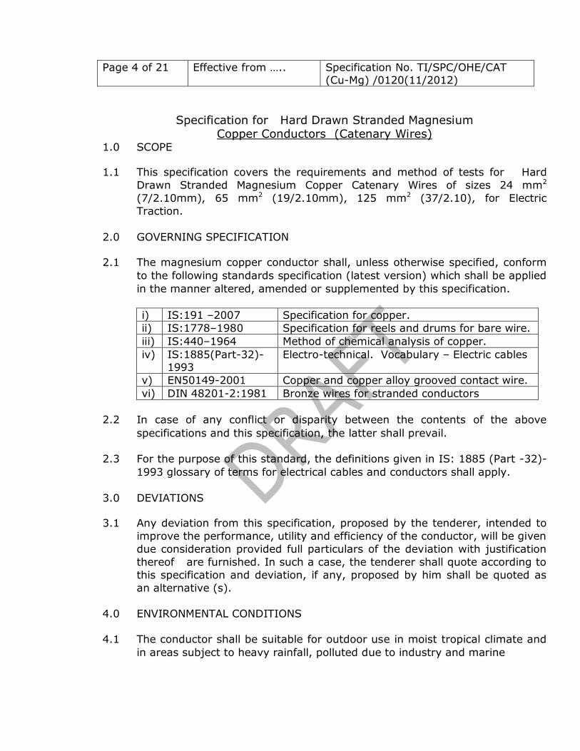
Specification for Hard Drawn Stranded Magnesium Copper Conductors (Catenary Wires)
1.0 SCOPE
1.1 This specification covers the requirements and method of tests for Hard
Drawn Stranded Magnesium Copper Catenary Wires of sizes 24 mm2
(7/2.10mm), 65 mm2 (19/2.10mm), 125 mm2 (37/2.10), for Electric
Traction.
2.0 GOVERNING SPECIFICATION
2.1 The magnesium copper conductor shall, unless otherwise specified, conform
to the following standards specification (latest version) which shall be applied
in the manner altered, amended or supplemented by this specification.
i) IS:191 –2007 Specification for copper.
ii) IS:1778–1980 Specification for reels and drums for bare wire.
iii) IS:440–1964 Method of chemical analysis of copper.
iv) IS:1885(Part-32)-
1993
Electro-technical. Vocabulary – Electric cables
v) EN50149-2001 Copper and copper alloy grooved contact wire.
vi) DIN 48201-2:1981 Bronze wires for stranded conductors
2.2 In case of any conflict or disparity between the contents of the above
specifications and this specification, the latter shall prevail.
2.3 For the purpose of this standard, the definitions given in IS: 1885 (Part -32)-
1993 glossary of terms for electrical cables and conductors shall apply.
3.0 DEVIATIONS
3.1 Any deviation from this specification, proposed by the tenderer, intended to
improve the performance, utility and efficiency of the conductor, will be given
due consideration provided full particulars of the deviation with justification
thereof are furnished. In such a case, the tenderer shall quote according to
this specification and deviation, if any, proposed by him shall be quoted as
an alternative (s).
4.0 ENVIRONMENTAL CONDITIONS
4.1 The conductor shall be suitable for outdoor use in moist tropical climate and
in areas subject to heavy rainfall, polluted due to industry and marine

Page 5 of 21 Effective from ….. Specification No. TI/SPC/OHE/CAT
(Cu-Mg) /0120(11/2012)
atmosphere and severe lightning. The limiting weather conditions which the
conductor has to withstand in service are indicated in TABLE - 1.
TABLE – 1
ENVIRONMENTAL CONDITIONS
SN Environmental condition Limits
i. Ambient air Temperature. 00 C to +500 C
ii. Maximum temperature of
metallic object under sun.
700 C
iii. Minimum temperature. -100 C
iv. Maximum relative humidity 100%
v. Annual rainfall Dry Arid regions and also heavy monsoon
affected regions with rainfall ranging from 1750mm to 6250mm.
vi. Maximum number of thunder
storm days per annum.
85
vii. Maximum number of dust storm days per annum.
35
viii. Number of rainy days per
annum
120
ix. Basic wind pressure 200 kgf/m2
x. Altitude Altitude: 1000m above mean sea level.
Altitude: 2000m in J& K area.
5.0 MATERIAL AND PROCESS OF MANUFACTURE
5.1 The copper used for fabrication of magnesium alloyed copper conductor shall
be electrolytic copper conforming to IS:191-2007 "Specification for Copper". The chemical composition of copper shall be as given in TABLE-2.
TABLE – 2
CHEMICAL COMPOSITION
Element % ppm
Cu+Ag >99.90%
Bi <10 ppm
Pb <5 ppm
Oxygen <450 ppm
5.2 The copper shall be alloyed with magnesium at the manufacturer's works.
The magnesium content shall be 0.2%. The presence of de-oxidizing agent
up to an extent which is not detrimental to the conductivity of the conductor

Page 6 of 21 Effective from ….. Specification No. TI/SPC/OHE/CAT
(Cu-Mg) /0120(11/2012)
may be permitted. The phosphorous content in magnesium copper billets
shall not exceed 50 ppm.
5.3 The copper magnesium billets shall be hot rolled to 8 – 10 mm diameter wire
rods. Alternatively, 8-10mm magnesium Copper Continuous cast wire rod shall be procured from RDSO approved reputed manufacturers. These wire
rods shall be pickled and washed and then drawn into the wires of required
sizes (2.10mm). These wires shall be stranded to finished Specification for
7/2.10mm, 19/2.10, 37/2.10, for Hard Drawn Stranded Magnesium Alloyed Copper Stranded Conductor in one operation.
.
6.0 FREEDOM FROM DEFECTS
6.1 The wire shall be smooth and free from all imperfections such as spills and
spurns.
7.0 JOINT IN WIRE BEFORE STRANDING
The wire shall be drawn in continuous lengths without joints except those
made in original rods before cold drawing.
8.0 JOINTS IN STRANDED CONDUCTORS
8.1 Normally joints in the wires during stranding are not permitted. However, in
the event of breakage of a wire during stranding, a joint in any wire shall be
so permitted that distance between two joints in the stranded conductor shall
not be less than 15 meters. Joints shall be Electric Butt Welded.
NOTE: Joints during stranding can be avoided by judiciously selecting the
length of wires in the spools.
8.2 Not more than four joints during stranding in 1525 m length of the stranded
conductor shall be permitted. Each such joint shall be painted to enable the
operator to identify the joint easily.
9.0 STRANDING
9.1 The conductor shall have right hand ordinary concentric lay. The successive
layers shall be twisted in opposite directions. The wires in each layer shall be evenly and closely stranded around the underlying wire(s). The lay ratio shall
be in accordance with Table-4.

Page 7 of 21 Effective from ….. Specification No. TI/SPC/OHE/CAT
(Cu-Mg) /0120(11/2012)
Note: Wires conform to the direction of the central part of the letter`Z’ when the
conductor is held vertically and viewed from the side. For left hand lay, the
wires conform to the central part of the letter `S’ when the conductor is held vertically and viewed from the side.
10. STANDARD RESISTANCE, WEIGHT AND SIZE OF STRANDED CONDUCTOR
After drawing, the wire shall have the diameter, weight and the resistance as
given in Table-3. The size, weight and resistance of stranded circular
conductor shall be as given in Table-4.
11 TOLERANCE ON THE DIMENSIONSS & WEIGHT OF CONDUCTOR
11.1 Solid Wire: After drawing, the diameter of the wires shall fall within the
appropriate maximum and minimum values specified in Table-3. The weight shall be in accordance with the values specified in Table-3 with a permitted
tolerance of +2%. The cross section of any wire after drawing shall not
depart from circularity by more than an amount corresponding to 2% on the standard diameter.
11.2 Stranded Conductor: The dimensions of stranded circular conductor shall
comply with requirements laid down in Table-4. The weight shall be in accordance with the values specified in Table-4 with a permitted tolerance of
+2%.
12. MECHINICAL PROPERTIES
12.1 The mechanical properties of the stranded wire shall be such that the tensile
strength when tested in accordance with Clause 18.6 shall not be less than
the appropriate value given in Table-3.
12.2 The wire shall comply with the requirement of wrapping test as given in
Clause 18.7.

Page 8 of 21 Effective from ….. Specification No. TI/SPC/OHE/CAT
(Cu-Mg) /0120(11/2012)
TABLE – 3
SOLID CIRCULAR MAGNESIUM COPPER WIRES
DIAMETER
Calculat
ed area of
magnesium
copper
Nominal equivale
nt area of hard
drawn copper
Weight per km
Resistance per km at 20° C corrected to
std Weight
Minimum Breaking Load on Diameter
Minimum Tensile
Strength.
Std. Max. Min. Std. Max. Min. Std. Max. Std. Max. Min.
mm mm mm mm2 mm2 Kg Kg Kg Ohm Ohm Kgf Kgf Kgf Kgf/mm2
(1) (2) (3) (4) (5) (6) (7) (8) (9) (10) (11) (12) (13) (14)
2.10 2.12 2.08 3.464 2.757 30.83 31.42 30.26 6.467 6.596 229 233 224 66.14
NOTE : 1 The values specified in column 11 are minimum with which wire shall comply before stranding.
NOTE : 2 The values specified in column 12 are the bases from which appropriate
breaking load of the stranded conductors listed in Table–4 have been calculated.
TABLE – 4
MAGENESIUM COPPER STRANDED CONDUCTOR
Nominal
equivalent area of Hard
Drawn Copper
No. of strands
and diameter 0f
Wire
Approx. overall
Diameter
Weight Per Km. Resistance per km at
20°C corrected to Standard Weight
Minimum breaking load of
Conductor
Calculated area of
Magnesium Copper.
Std Max Min Std Max
mm2 mm2 mm Kg Kg Kg Ohm Ohm Kgf mm2
(1) (2) (3) (4) (5) (6) (7) (8) (9) (10)
19.14 7/2.10 6.3 217.60 221.76 213.58 0.9325 0.9498 1432.7 24.05
51.62 19/2.10 10.5 594.40 605.78 583.41 0.3458 0.3522 3915.9 64.85
99.98 37/2.10 14.7 1163.52 1185.79 1142.01 0.1787 0.1820 7625.7 125.60

Page 9 of 21 Effective from ….. Specification No. TI/SPC/OHE/CAT
(Cu-Mg) /0120(11/2012)
TABLE – 5
LAY RATIO
No. of wires
LAYER AND NUMBER OF WIRES
First Layer Second Layer Third layer
Max. Min Max. Min Max. Min.
7/2.10 25 20 - - - -
19/2.10 25 20 17.5 15 - -
37/2.10 25 20 17.5 15 15 12.5
13.0 TESTS
13.1 After a purchase order is placed for supply of Magnesium Copper Catenary
Wire for overhead Railway Traction, the internal test results for all the tests
specified in Clause – 14.0 shall be furnished by the successful tenderer to
the Director General (Traction Installation)/Research Designs & Standards
Organisation, Manak Nagar, Lucknow - 226 011, within the period stipulated
for prototype approval in the order.
13.2 Any changes required in the process of manufacture or the prototype as
desired by the Director General (Traction Installation)/Research Designs &
Standards Organisation (RDSO) shall be carried out expeditiously by the
manufacturer.
13.3 Type testing schedule
Prior to giving a call to the Director General (Traction Installation) / Research
Designs & Standards Organisation for inspection and testing of the prototype,
the manufacturer shall submit a detailed test schedule consisting of
schematic diagrams for each of the tests and the number of days required to
complete all the tests at one stretch. Once the schedule is approved, the
tests shall invariably be done accordingly. However, during the process of
type testing or even later, the purchaser reserves the right to conduct any
additional test(s) besides those specified herein, to his satisfaction or for
gaining additional information and knowledge. In case any dispute or
disagreement arises between the manufacturer and representative of the
Director General (Traction Installations) / RDSO during the process of testing
as regards the procedure for type tests and/or the interpretation and
acceptability of the results of type test, it shall be brought to the notice of
the Director General (Traction Installation) /RDSO as the case may be,
whose decision shall be final and binding.

Page 10 of 21 Effective from ….. Specification No. TI/SPC/OHE/CAT
(Cu-Mg) /0120(11/2012)
13.4 All the tests specified in the specification shall be carried out at the
manufacturer's works. The manufacturer shall arrange all the necessary
machinery, apparatus, labour and assistance required for conducting the
tests without any extra cost.
13.5 In the event of the tests not being carried through to completion at one
stretch for any reason attributable to the manufacturer and it is required for
the representative of the Director General (Traction Installation) /RDSO to go
once or several times to the works of the manufacturer or other place(s) for
continuing and/or completing the tests on the prototype (s), the
manufacturer shall reimburse to the Director General (Traction Installations)/
RDSO the cost for the representative's visits to works or other place(s) more
than once. The cost as claimed by the Director General (Traction Installation)
/ RDSO shall be paid through a demand draft as advised to the
manufacturer.
14.0 Type Tests
14.1 The manufacturer shall manufacture at least 500m length of stranded
conductor and offer for type tests. The type tests shall be conducted on the
stranded conductor and on the wires before and after stranding. For carrying
out the tests on wire after stranding, the samples of stranded conductor
selected shall be opened and mixed and then three wires at random shall be
selected. The following type tests shall constitute the type tests.
i) Visual Examination of Copper Wire Bars/Copper Cathodes/CCC Wire
Rods and Stranded Conductor. ii) Measurement of Diameter of individual Wire and Stranded Conductor.
iii) Measurement of weight of Wire and Conductor.
iv) Measurement of lay length and lay ratio of each layer of Stranded Conductor.
v) Measurement of Electrical Resistance of Wire and Stranded Conductor.
vi) Tensile Test on Wires.
vii) Wrapping Test on Wires. viii) Chemical Composition of Copper Wire Bar/Copper Cathodes/CCC Wire
Rods and Cu-Mg billets.
Each test shall be conducted on three samples.
Note-1 The entire manufacturing process upto the finished Conductor shall be witnessed by the Representative of Director General (Traction
Installation), Research Designs & Standards Organisation, Lucknow. For
Chemical Composition, the Cu+Ag content of the Wire Bars or Copper
Cathodes or CCC Wire Rods shall be determined as per IS:440-1964. The trace elements of the material of wire bar or cathode copper or CCC Wire

Page 11 of 21 Effective from ….. Specification No. TI/SPC/OHE/CAT
(Cu-Mg) /0120(11/2012)
Rods shall be determined by Spectrometer. The oxygen content shall be
verified from the supplier’s certificate. The Magnesium and phosphorous
content shall be determined on at least half the Cu Mg billets from each melt.
Note-2 If the prototype of the conductor conforming to this Specification has already been approved in connection with previous supplies to Indian
Railways, fresh testing of prototype of the conductor may be waived at
the discretion of the Director General (Traction Installation), Research
Designs & Standards Organisation, Lucknow provided that no changes whatsoever in the material or process of manufacture have been made.
However, the Director General (Traction Installation), Research Designs &
Standards Organisation, Lucknow reserves the right to witness entire manufacturing process and type tests if he deems it necessary to do so in
the light of experience gained from previous supplies.
15.0 ACCEPTANCE TEST
15.1 The following shall constitute the acceptance test
i) Visual Examination ii) Measurement of Diameter of individual Wire and Stranded Conductor
iii) Measurement of Weight of Wire
iv) Measurement of Lay Length and Lay Ratio of each layer of Stranded Conductor.
v) Measurement of Electrical Resistance of Wire.
vi) Tensile Test on individual Wire of Strands.
vii) Wrapping Test on Wire viii) Chemical Composition
ix) Weight of Drums.
15.2 Only after clear written approval of the results of the tests on the prototype
is communicated by the Director General (Traction Installation), Research
Designs & Standards Organisation, Lucknow, to the manufacturer, he shall take up bulk manufacture of the conductor which shall be strictly with the
same material and process of manufacture as adopted for the prototype. In
no circumstances shall be material other than that adopted during the
manufacture of the prototype be used for bulk manufacture.
15.3 SAMPLING
One sample of Cu-Mg Stranded Conductor shall be taken from each drum for
the tests prescribed in Clause 15.1.

Page 12 of 21 Effective from ….. Specification No. TI/SPC/OHE/CAT
(Cu-Mg) /0120(11/2012)
15.4 CRITERIA FOR ACCEPTANCE
The sample of wire and Conductor taken from each Drum shall be subjected
to all the tests prescribed in Clause 15.1. The Wire and Conductor in the
Drum shall be deemed to have passed the tests if the samples pass all the
tests. If a sample fails in more than one test, the Drum shall be rejected. If
sample fail in anyone of the tests, two more samples shall be taken from the
same drum and subjected to all the tests. If any sample fail in any tests out
of two samples taken, the drum shall be rejected and the wires and
conductor in the rejected drum shall be cut into lengths of less than 50 m.
16.0 ROUTINE TESTS
16.1 The tests indicated in Clause 15.1 shall constitute Routine Tests and shall be
carried out on the samples from each drum.
17.0 MANUFACTURE’S TEST
17.1 In addition to the tests prescribed above, the following tests shall be
conducted by the manufacturer in the course of fabrication and the records
maintained.
i) The Chemical Composition including trace elements of every lot of wire bars
or cathodes or CCC Wire Rods for chemical composition. The chemical
composition shall meet the requirement laid down in Clause 5.1.
ii) The chemical composition of atleast half the billets (these must include first
and last billet also ) of every melt for Mg, Cu and P contents.
iii) Trace elements excluding Mg of at least one billet from every melt by
spectrometer. The other impurities shall not exceed as given in Table -2.
iv) Tests on each spool of 2.10/2.64/2.92/3.35mm diameter wire after drawing
for Tensile Strength, Wrapping Test, Measurement of Diameter, Weight and Electric Resistance. The spool shall be rejected if wire in the spool does not
conform to the requirements of specification. The rejected Wire may be re-
melted with new stock in small quantity.
v) Weighment of every Drum for Tare Weight and Gross Weight.
17.2 Records of these tests shall be maintained by the manufacturer and shall be
produced to the Inspecting Engineer at the time of prototype testing /Re-
assessment /Quality Audit during Acceptance Tests.

Page 13 of 21 Effective from ….. Specification No. TI/SPC/OHE/CAT
(Cu-Mg) /0120(11/2012)
18. TEST MEATHODS
18.1 VISUAL EXAMINATION
The Copper Wire Bars /Copper Cathodes/CCC Wire Rods, Wires and Stranded
Conductor shall be free from shrink, holes, cold sets, pits, sloping edges,
concave tops etc. The Copper Cathode shall be tough, dense and free from
loose or brittle lumps, modules and other undue out growth. The surface
shall be free from slime and copper sulphate. The Wire and Stranded
Conductor shall be visually examined. The wire shall be clean smooth and
free from harmful defects. The Strands in the Conductor shall be evenly laid
without any loose Wire. The construction shall be checked for laying of
strands of different layers and for the total number of wires. The construction
shall be as per Clause 9 of the Specification.
18.2 MEASUREMENT OF DIAMETER OF WIRE & STRANDED CONDUCTOR.
18.2.1 The Diameter shall be measured by means of Ratchet Micrometer or a
Digital Micrometer between two flat circular studs of minimum diameter of
mm. Two measurements at right angles of the wire as well as of the stranded conductor shall be taken at three sections and average of 6 readings shall be
taken as diameter of the wire/stranded conductor.
18.3 MEASUREMENT OF WEIGHT OF WIRE & STRANDED CONDUCTOR
18.3.1The weight of wire and stranded conductor per kilometer shall be measured
by weighing three samples each of 50 cm (approximate) length by a balance
of accuracy of + 1 gm for conductor and + 0.1 gm for wire.
18.4 MEASUREMENT OF LAY LENGTH & LAY RATIO OF EACH LAYER OF STRANDED CONDUCTOR
18.4.1The lay length, i.e. the axial length of a complete turn of the helix formed by
the wire in a layer of the stranded conductor, of each layer shall be measured by a vernier caliper or by any other method. The measured Lay Length when
divided by the mean diameter of helix will be the lay ratio of that layer.
18.5 MEASUREMENT OF ELECTRICAL RESISTANCE OF WIRE & STRANDED
CONDUCTOR
18.5.1 The D.C. Electrical Resistance of the wire and Stranded Conductor shall be
measured by digital micro-ohm meter or Double Kelvin’s Bridge at room
temperature. The Conductor shall be in the test room which shall be at a
reasonably constant temperature for sufficient time. The measurement shall
be made on a sample length of not less than 50 cm to an accuracy of one

Page 14 of 21 Effective from ….. Specification No. TI/SPC/OHE/CAT
(Cu-Mg) /0120(11/2012)
part per thousand. The Inspecting Engineer shall have the right to test the
accuracy of the instrument by another wire of known resistance.
The Electrical Resistance per kilometer of the test sample (Wire/Stranded
Conductor) multiplied by W x C/K shall not exceed on appropriate maximum
value given in TABLE - 3 and TABLE - 4.
Where K = Standard weight per km,
W = Weight per km. of test sample (wire/stranded conductor) and
C = multiplier constant for correction to 20° C
The multiplier constant `C’ for the temperature at which the
Resistance measurement have been made in accordance with the
temperature co-efficient of resistance of Cu-Mg alloy at 20oC which is
0.00185 per oC.
18.6 TENSILE TEST ON INDIVIDUAL WIRE
18.6.1 The load on the wire shall be applied gradually and the rate of separation of
the jaws of the testing machine shall not be greater than 10 cm per minute and shall be so adjusted that the total time of the testing from the moment of the application of the load till fracture is between 15 and 60 seconds.
NOTE: The strength of Stranded Conductor in terms of the sum of the strengths
of the individual wires may be assumed to be not less than as indicated in
TABLE- 6.

Page 15 of 21 Effective from ….. Specification No. TI/SPC/OHE/CAT
(Cu-Mg) /0120(11/2012)
TABLE – 6 MULTIPLIER CONSTANT FOR COVERSION OF
ELECTRICAL RESISTANCE TO 200C.
Multiplier constant for converting resistance of hard drawn Magnesium Copper
(wire/conductor) at any temperature between 50 C and 450 C to a temperature of
200 C is in column 2 and 5 and its reciprocal is in column 3 and 6 respectively for converting resistance at 200 C to that at any other temperature between 50 C and
450C.
Temperature 0C
Multiplier
constant
Reciprocal
of constant
Temperature 0C
Multiplier
constant
Reciprocal
of constant
5 1.028 0.973 24.5 0.992 1.008
5.5 1.027 0.974 25 0.991 1.009
6 1.026 0.975 25.5 0.990 1.010
6.5 1.025 0.976 26 0.989 1.011
7 1.024 0.977 26.5 0.988 1.012
7.5 1.023 0.978 27 0.987 1.013
8 1.022 0.978 27.5 0.986 1.014
8.5 1.021 0.979 28 0.985 1.015
9 1.020 0.980 28.5 0.984 1.016
9.5 1.0195 0.981 29 0.983 1.017
10 1.019 0.981 29.5 0.9825 1.018
10.5 1.018 0.982 30 0.982 1.018
11 1.017 0.983 30.5 0.981 1.019
11.5 1.016 0.984 31 0.980 1.020
12 1.015 0.985 31.5 0.979 1.021
12.5 1.014 0.986 32 0.978 1.002
13 1.013 0.987 32.5 0.977 1.023
13.5 1.012 0.988 33 0.976 1.025
14 1.011 0.989 33.5 0.975 1.026
14.5 1.010 0.990 34 0.974 1.027
15 1.009 0.991 34.5 0.973 1.028
15.5 1.008 0.992 35 0.972 1.029
16 1.007 0.993 35.5 0.971 1.030
16.5 1.0065 0.994 36 0.970 1.031
17 1.006 0.994 36.5 0.9695 1.0315
17.5 1.005 0.995 37 0.969 1.032
18 1.004 0.996 37.5 0.968 1.033
18.5 1.003 0.997 38 0.967 1.034
19 1.002 0.998 38.5 0.966 1.035
19.5 1.001 0.999 39 0.965 1.036
Temperature Multiplier Reciprocal Temperature Multiplier Reciprocal

Page 16 of 21 Effective from ….. Specification No. TI/SPC/OHE/CAT
(Cu-Mg) /0120(11/2012)
0C constant of constant 0C constant of constant
20 1.000 1.000 39.5 0.964 1.037
20.5 0.999 1.001 40 0.963 1.038
21 0.998 1.002 40.5 0.962 1.040
21.5 0.997 1.003 41 0.961 1.041
22 0.996 1.004 41.5 0.960 1.042
22.5 0.995 1.005 42 0.959 1.043
23 0.994 1.006 42.5 0.958 1.044
23.5 0.9935 1.0065 43 0.957 1.045
24 0.993 1.007 43.5 0.9565 1.0455
44 0.956 1.046
44.5 0.955 1.047
45 0.954 1.048
NOTE – 1: Given in resistance of wire/stranded conductor at T°C, the resistance
at 20°C, the resistance at 20° C is found by multiplying the resistance at T°C by the constant for T°C given in Column 2 and 5 conversely,
given the resistance at 20°C the corresponding resistance at T°C is
found by multiplying the resistance at 20° C by the reciprocal against
T °C given in Column 3 & 6.
NOTE – 2 : The temperature resistance co-efficients of magnesium copper have
been taken as 0.00185 per ˚C at 20˚C as per EN 50149-2001 for
0.2% Mg content.
18.6.2 TENSILE STRENGTH
This test shall apply to wires of all diameters before stranding and also
to the wires taken from the stranded conductor. The tensile strength of a wire before stranding when tested in the manner as explained below,
shall be not less than the appropriate value given in T ABLE-3. If it is
not possible to test the wires before stranding, the test may be made
on wires taken from the stranded conductor. In such cases the tensile
strength of any of the wire shall be not less than 92.5% of the value
given in T ABLE-3 and the average tensile strength of all the wires in a stranded conductor shall be not less than 94% of the value specified in
TABLE-3.
18.6.2.1 The load shall be applied gradually and the rate of separation of the
jaws of the testing machine shall not be greater than 10 cm per minute and shall be so adjusted that the total time of the testing from the moment of the application of the load till fracture is between 15 and 60 seconds.

Page 17 of 21 Effective from ….. Specification No. TI/SPC/OHE/CAT
(Cu-Mg) /0120(11/2012)
NOTE : The strength of stranded conductor in terms of the sum of the
strengths of the individual wires may be assumed to be not less than
as indicated in TABLE- 7.
TABLE - 7
Number of
Wires in
Stranded
Conductor
Percentage strength based on
the strength of wires when
taken from the Stranded
Conductor and tested
Percentage strength
based on the strength
of the wire before
Stranding.
7 93 90
19 93 90
37 93 90
The average tensile strength of all the wires in a stranded conductor shall not
be less than 94% of the value specified in Table-3.
18.7 WRAPPING TEST ON INDIVIDUAL WIRE 18.7.1 The wire shall be wrapped round a wire of its own diameter to form a close
helix of 8 turns. Six turns shall then be unwrapped and then closely re-
wrapped in the same direction as the first wrapping. Wire shall not break
during the test.
18.8 CHEMICAL COMPOSITION
18.8.1 For Type Test, the trace elements in wire bar or Cathode Copper or CCC
Wire Rods shall be determined by Spectrometer. The Oxygen content shall
be verified from supplier’s certificate. The copper and silver content of the wire bars or Copper Cathode shall be determined in accordance with
IS:440-1964. The chemical composition of copper wire bar shall be as given
in Table-2. The Mg content, phosphorous content and copper content on at
least half the billets including the first and last billets from the melt shall be
determined as per the relevant standard methods. For acceptance test one
composite sample from the sample selected from each drum shall be analyzed for copper, Mg and phosphorus content.
18.9 Weighment of three or one fifth of offered Drums whichever is higher shall be
made for Gross Weight and recorded.
19. LENGTH OF CONDUCTOR
The conductor shall be ordered in specified lengths which may vary between

Page 18 of 21 Effective from ….. Specification No. TI/SPC/OHE/CAT
(Cu-Mg) /0120(11/2012)
500 m and 3200 m and shall be supplied as per the following tolerances.
Length under 750 m + 10.0 m
- 0.0 m
Lengths of 750 m & above + 20.0 m
- 0.0 m
20. PACKING AND MARKING
20.1 The Magnesium Copper Stranded Conductor shall be delivered to the
purchaser properly wound on drums. Each length of stranded conductor shall be supplied tightly coiled on a suitable wooden drum absolutely without any
kinks. A drum shall carry only one continuous length of stranded conductor.
Paper shall be provided between each layer of conductor while winding on the drum during manufacturing process.
The drums shall conform to IS:1778-1980. The spindle plates of the
drums shall have a square hole 105 mm x 105 mm to permit the passage of a square axle of maximum size 100 mm x 100 mm. The use of spindle plates
with the hole of any other shape or size shall be subjected to agreement
between the purchaser and the manufacturer.
20.2 The labeling on drum shall include –
a) The manufacturer’s brand or mark.
b) Size of the conductor.
c) The actual length of the wire on the drum
d) Weight of drum (net and gross)
e) Number of joints provided during stranding with identification of joints.
f) Drum number and
g) Purchase Order no. and the name of the consignee.

Page 19 of 21 Effective from ….. Specification No. TI/SPC/OHE/CAT
(Cu-Mg) /0120(11/2012)
Appendix – ‘A’ to
Specification No. TI/SPC/OHE/CAT (Cu-Mg)/0120(11/2012)
A-1 The stranded magnesium copper conductors are used as catenary, bridle wire
and terminating wire in the traction overhead equipment and are very
important components of the system. Any failure of the conductor in service
has very serious repercussions. It is, therefore, essential that the
manufacture of the conductors is to the highest standards of reliability, so as
to achieve a maintenance free service of 40-50 years.
A-2 The 8 mm - 10 mm diameter wire rods should preferably be jointed together
so that the drawing of 2.10 mm diameter wire is continuous, during drawing,
spools of lengths specified by the purchaser may be cut to obtain the wire of
exact length and avoid the jointing of wire during stranding, except in the
event of breakage.
A-3 The manufacturers of magnesium copper conductors should, therefore, be
equipped with the following facilities:
i) Furnaces for making magnesium copper alloy with suitable temperature
measuring equipment.
ii) Well equipped laboratory having facility of measuring quickly Magnesium,
phosphorous, and other trace elements by spectroscopic method so as to
maintain a close check on the quality of production.
iii) Facility for chopping of the top of wire bars and scalping.
iv) Rolling Mill* for manufacture of 8 – 10 mm diameter wire rods.
v) Pickling, wire drawing and stranding equipment.
vi) l-tonne Universal Tensile Testing Machine.
vii) Equipment for measurement of electrical resistance and instruments for
measurement of diameter, weight and lay ratio etc.
* In case the manufacturers of the magnesium copper conductor does not have rolling mill of their own and intend to get the rolling done
through some outside agency, it is essential that a joint application is
submitted to Director General (TI), RDSO by both the parties for
registration/approval. In such a case of joint registration, with-drawl of
approval of one agency due to any reason what so-ever shall
automatically lead to de-registration of other agency also.

Page 20 of 21 Effective from ….. Specification No. TI/SPC/OHE/CAT
(Cu-Mg) /0120(11/2012)
Appendix – ‘B’ to
Specification No. TI/SPC/OHE/CAT (Cu-Mg)/0120(11/2012)
NOTES ON THE CALCULATION ON TABLE - 4
B-1 DATA CONCERNING STRANDED CONDUCTORS
B-1.0 The values of TABLE-4 have been calculated on the following basis.
B-1.1 When straightened out, each wire in any particular layer of the stranded
conductor, except the central wire, is assumed to be longer than the
stranded conductor by an amount depending on the mean lay ratio (See
5,2) of that layer as per TABLE - 5.
TABLE - 8
INCREASE IN LENGTH OF WIRE DUE TO STRANDING
FIRST LAYER SECOND LAYER THIRD LAYER
MEAN LAY RATIO 22.50 16.25 13.75
PERCENTAGE
INCREASE IN
LENGTH OF WIRE (Calculated)
0.97 1.85 2.50
B 1.2 The weight of each wire in any particular layer of a stranded conductor,
except the central wire, will be greater than that of an equal length of
straight wire by an amount depending on the mean lay ratio of that layer
as indicated in para B 1. 1 above.
The area, weight and resistance of the wire have been calculated by
multiplying the corresponding values for one of the single wire of which the
conductor is composed by the constants given in TABLE - 9.
TABLE-9 MULTIPLIER CONSTANTS FOR STRANDED CONDUCTOR
No. of wires in stranded
conductor
Constant
For Area For Weight For resistance
7 6.942 7.058 0.1440
19 18.720 19.280 0.0534
37 36.260 37.740 0.0276

Page 21 of 21 Effective from ….. Specification No. TI/SPC/OHE/CAT
(Cu-Mg) /0120(11/2012)
B 1.3 CALCULATED AREA
This term denotes the area of a solid magnesium copper rod which would
have the same resistance as the stranded conductor, assuming
conductivity of both to be the same. This area, therefore, takes into
account the assumed increase of resistance of each wire except the central
wire and can be determined by multiplying the area of anyone wire by a
constant given in TABLE -9. This constant is the reciprocal of the constant
for calculating the resistance.
B 1.4 NOMINAL COPPER AREA
This term denotes in rounded figures the area of a solid hard drawn copper
rod of resistance approximately equal to that of the magnesium copper
stranded conductor.
B 1.5 TABLE - 9 has been calculated for, and is only applicable to the standard
constructions of stranded conductors specified in this standard.
***