SPECIFICATIONS - Hummer forum . dehummerforum.de/download/2008_ENGINE_ELECTRICAL.pdf · 2009-03-29...
172
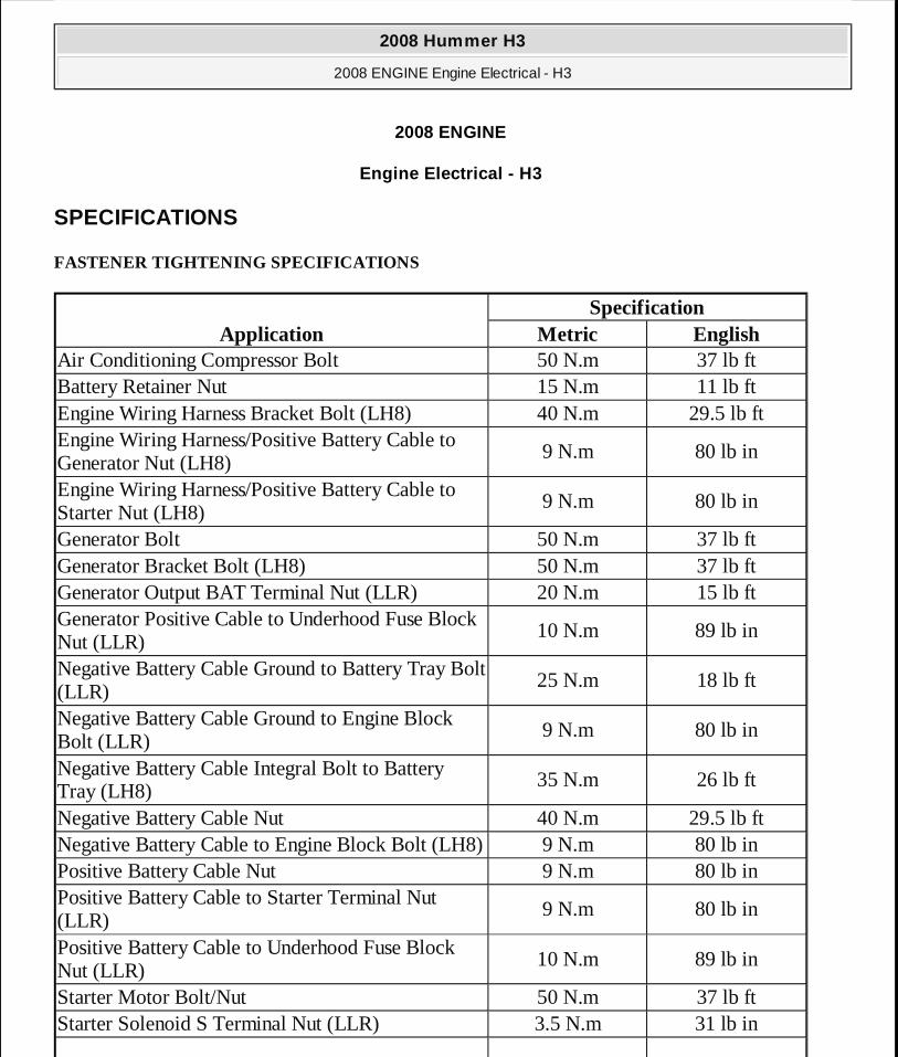
2008 ENGINE Engine Electrical - H3 SPECIFICATIONS FASTENER TIGHTENING SPECIFICATIONS Application Specification Metric English Air Conditioning Compressor Bolt 50 N.m 37 lb ft Battery Retainer Nut 15 N.m 11 lb ft Engine Wiring Harness Bracket Bolt (LH8) 40 N.m 29.5 lb ft Engine Wiring Harness/Positive Battery Cable to Generator Nut (LH8) 9 N.m 80 lb in Engine Wiring Harness/Positive Battery Cable to Starter Nut (LH8) 9 N.m 80 lb in Generator Bolt 50 N.m 37 lb ft Generator Bracket Bolt (LH8) 50 N.m 37 lb ft Generator Output BAT Terminal Nut (LLR) 20 N.m 15 lb ft Generator Positive Cable to Underhood Fuse Block Nut (LLR) 10 N.m 89 lb in Negative Battery Cable Ground to Battery Tray Bolt (LLR) 25 N.m 18 lb ft Negative Battery Cable Ground to Engine Block Bolt (LLR) 9 N.m 80 lb in Negative Battery Cable Integral Bolt to Battery Tray (LH8) 35 N.m 26 lb ft Negative Battery Cable Nut 40 N.m 29.5 lb ft Negative Battery Cable to Engine Block Bolt (LH8) 9 N.m 80 lb in Positive Battery Cable Nut 9 N.m 80 lb in Positive Battery Cable to Starter Terminal Nut (LLR) 9 N.m 80 lb in Positive Battery Cable to Underhood Fuse Block Nut (LLR) 10 N.m 89 lb in Starter Motor Bolt/Nut 50 N.m 37 lb ft Starter Solenoid S Terminal Nut (LLR) 3.5 N.m 31 lb in 2008 Hummer H3 2008 ENGINE Engine Electrical - H3 2008 Hummer H3 2008 ENGINE Engine Electrical - H3
Transcript of SPECIFICATIONS - Hummer forum . dehummerforum.de/download/2008_ENGINE_ELECTRICAL.pdf · 2009-03-29...
2008 ENGINE
Engine Electrical - H3
SPECIFICATIONS
FASTENER TIGHTENING SPECIFICATIONS
ApplicationSpecification
Metric EnglishAir Conditioning Compressor Bolt 50 N.m 37 lb ftBattery Retainer Nut 15 N.m 11 lb ftEngine Wiring Harness Bracket Bolt (LH8) 40 N.m 29.5 lb ftEngine Wiring Harness/Positive Battery Cable to Generator Nut (LH8)
9 N.m 80 lb in
Engine Wiring Harness/Positive Battery Cable to Starter Nut (LH8)
9 N.m 80 lb in
Generator Bolt 50 N.m 37 lb ftGenerator Bracket Bolt (LH8) 50 N.m 37 lb ftGenerator Output BAT Terminal Nut (LLR) 20 N.m 15 lb ftGenerator Positive Cable to Underhood Fuse Block Nut (LLR)
10 N.m 89 lb in
Negative Battery Cable Ground to Battery Tray Bolt (LLR)
25 N.m 18 lb ft
Negative Battery Cable Ground to Engine Block Bolt (LLR)
9 N.m 80 lb in
Negative Battery Cable Integral Bolt to Battery Tray (LH8)
35 N.m 26 lb ft
Negative Battery Cable Nut 40 N.m 29.5 lb ftNegative Battery Cable to Engine Block Bolt (LH8) 9 N.m 80 lb inPositive Battery Cable Nut 9 N.m 80 lb inPositive Battery Cable to Starter Terminal Nut (LLR)
9 N.m 80 lb in
Positive Battery Cable to Underhood Fuse Block Nut (LLR)
10 N.m 89 lb in
Starter Motor Bolt/Nut 50 N.m 37 lb ftStarter Solenoid S Terminal Nut (LLR) 3.5 N.m 31 lb in
2008 Hummer H3
2008 ENGINE Engine Electrical - H3
2008 Hummer H3
2008 ENGINE Engine Electrical - H3
MY
Sunday, March 29, 2009 10:52:04 PM Page 1 © 2005 Mitchell Repair Information Company, LLC.
MY
Sunday, March 29, 2009 10:52:17 PM Page 1 © 2005 Mitchell Repair Information Company, LLC.
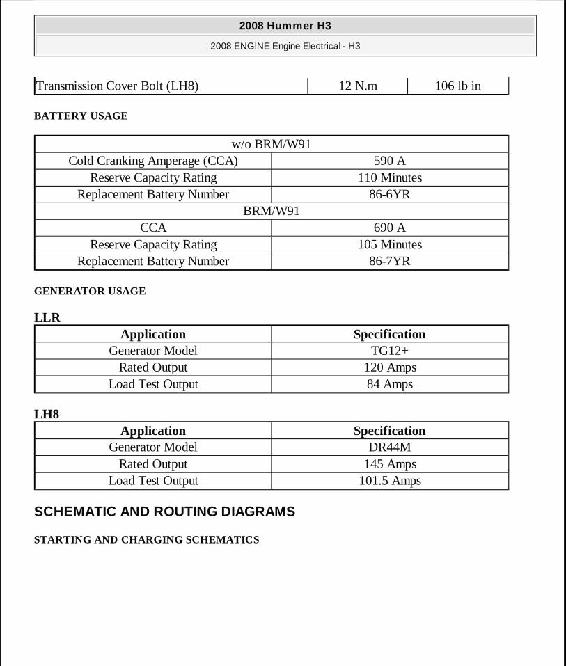
BATTERY USAGE
GENERATOR USAGE
LLR
LH8
SCHEMATIC AND ROUTING DIAGRAMS
STARTING AND CHARGING SCHEMATICS
Transmission Cover Bolt (LH8) 12 N.m 106 lb in
w/o BRM/W91Cold Cranking Amperage (CCA) 590 A
Reserve Capacity Rating 110 MinutesReplacement Battery Number 86-6YR
BRM/W91CCA 690 A
Reserve Capacity Rating 105 MinutesReplacement Battery Number 86-7YR
Application SpecificationGenerator Model TG12+
Rated Output 120 AmpsLoad Test Output 84 Amps
Application SpecificationGenerator Model DR44M
Rated Output 145 AmpsLoad Test Output 101.5 Amps
2008 Hummer H3
2008 ENGINE Engine Electrical - H3
MY
Sunday, March 29, 2009 10:52:04 PM Page 2 © 2005 Mitchell Repair Information Company, LLC.
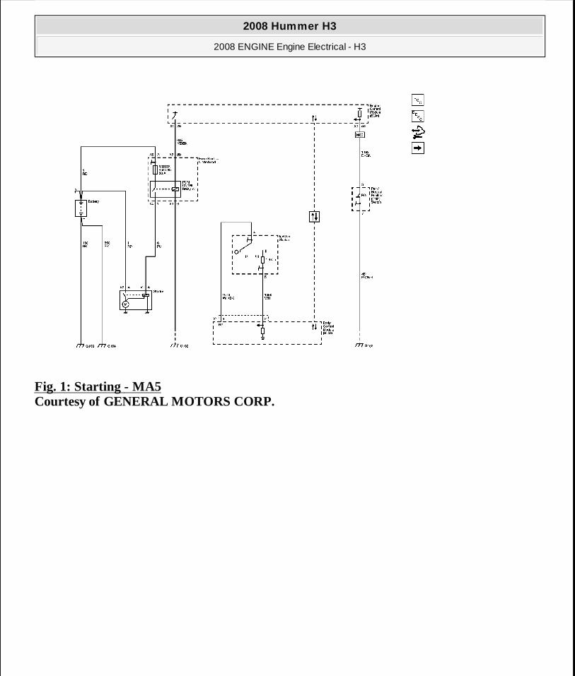
Fig. 1: Starting - MA5 Courtesy of GENERAL MOTORS CORP.
2008 Hummer H3
2008 ENGINE Engine Electrical - H3
MY
Sunday, March 29, 2009 10:52:04 PM Page 3 © 2005 Mitchell Repair Information Company, LLC.
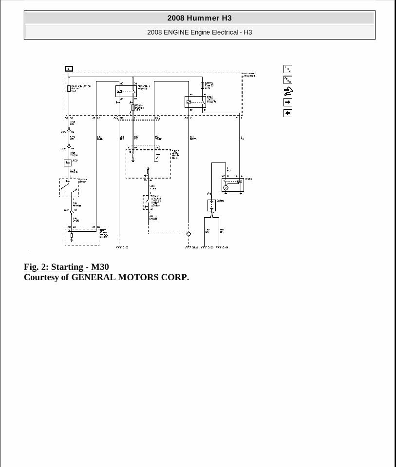
Fig. 2: Starting - M30 Courtesy of GENERAL MOTORS CORP.
2008 Hummer H3
2008 ENGINE Engine Electrical - H3
MY
Sunday, March 29, 2009 10:52:04 PM Page 4 © 2005 Mitchell Repair Information Company, LLC.
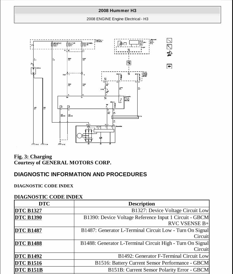
Fig. 3: Charging Courtesy of GENERAL MOTORS CORP.
DIAGNOSTIC INFORMATION AND PROCEDURES
DIAGNOSTIC CODE INDEX
DIAGNOSTIC CODE INDEX DTC Description
DTC B1327 B1327: Device Voltage Circuit LowDTC B1390 B1390: Device Voltage Reference Input 1 Circuit - GBCM
RVC VSENSE B+DTC B1487 B1487: Generator L-Terminal Circuit Low - Turn On Signal
CircuitDTC B1488 B1488: Generator L-Terminal Circuit High - Turn On Signal
CircuitDTC B1492 B1492: Generator F-Terminal Circuit LowDTC B1516 B1516: Battery Current Sensor Performance - GBCMDTC B151B B151B: Current Sensor Polarity Error - GBCM
2008 Hummer H3
2008 ENGINE Engine Electrical - H3
MY
Sunday, March 29, 2009 10:52:04 PM Page 5 © 2005 Mitchell Repair Information Company, LLC.
DIAGNOSTIC STARTING POINT - ENGINE ELECTRICAL
Begin the system diagnosis with Diagnostic System Check - Vehicle . The Diagnostic System Check - Vehicle will provide the following information:
� The identification of the control modules which command the system � The ability of the control modules to communicate through the serial data circuit � The identification of any stored diagnostic trouble codes (DTCs) and their status
The use of the Diagnostic System Check - Vehicle will identify the correct procedure for diagnosing the system and where the procedure is located.
DTC B1327
Diagnostic Instructions
� Perform the Diagnostic System Check - Vehicle prior to using this diagnostic procedure.
� Review Strategy Based Diagnosis for an overview of the diagnostic approach.
� Diagnostic Procedure Instructions provides an overview of each diagnostic category.
DTC Descriptor
DTC B1327
Device Voltage Circuit Low
Diagnostic Fault Information
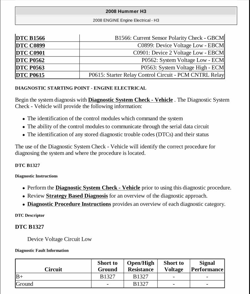
DTC B1566 B1566: Current Sensor Polarity Check - GBCMDTC C0899 C0899: Device Voltage Low - EBCMDTC C0901 C0901: Device 2 Voltage Low - EBCMDTC P0562 P0562: System Voltage Low - ECMDTC P0563 P0563: System Voltage High - ECMDTC P0615 P0615: Starter Relay Control Circuit - PCM CNTRL Relay
CircuitShort to Ground
Open/High Resistance
Short to Voltage
Signal Performance
B+ B1327 B1327 - -Ground - B1327 - -
2008 Hummer H3
2008 ENGINE Engine Electrical - H3
MY
Sunday, March 29, 2009 10:52:04 PM Page 6 © 2005 Mitchell Repair Information Company, LLC.
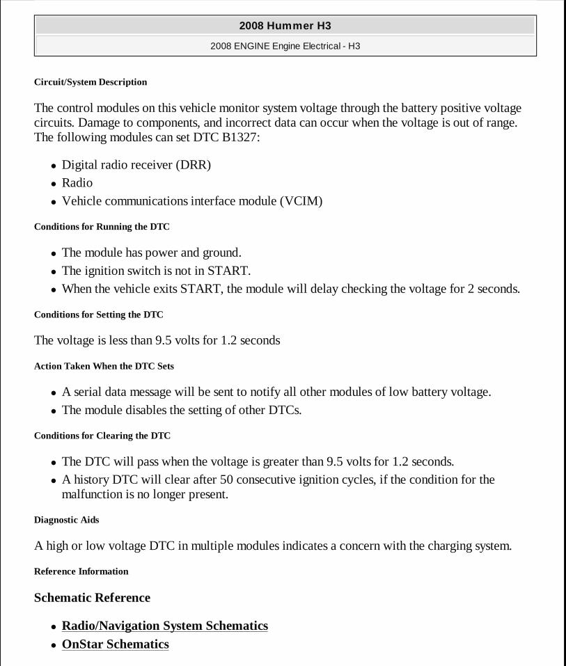
Circuit/System Description
The control modules on this vehicle monitor system voltage through the battery positive voltage circuits. Damage to components, and incorrect data can occur when the voltage is out of range. The following modules can set DTC B1327:
� Digital radio receiver (DRR) � Radio � Vehicle communications interface module (VCIM)
Conditions for Running the DTC
� The module has power and ground. � The ignition switch is not in START. � When the vehicle exits START, the module will delay checking the voltage for 2 seconds.
Conditions for Setting the DTC
The voltage is less than 9.5 volts for 1.2 seconds
Action Taken When the DTC Sets
� A serial data message will be sent to notify all other modules of low battery voltage. � The module disables the setting of other DTCs.
Conditions for Clearing the DTC
� The DTC will pass when the voltage is greater than 9.5 volts for 1.2 seconds. � A history DTC will clear after 50 consecutive ignition cycles, if the condition for the
malfunction is no longer present.
Diagnostic Aids
A high or low voltage DTC in multiple modules indicates a concern with the charging system.
Reference Information
Schematic Reference
� Radio/Navigation System Schematics � OnStar Schematics
2008 Hummer H3
2008 ENGINE Engine Electrical - H3
MY
Sunday, March 29, 2009 10:52:04 PM Page 7 © 2005 Mitchell Repair Information Company, LLC.
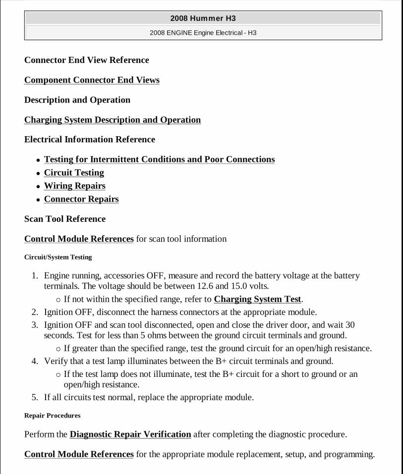
Connector End View Reference
Component Connector End Views
Description and Operation
Charging System Description and Operation
Electrical Information Reference
� Testing for Intermittent Conditions and Poor Connections
� Circuit Testing
� Wiring Repairs
� Connector Repairs
Scan Tool Reference
Control Module References for scan tool information
Circuit/System Testing
1. Engine running, accessories OFF, measure and record the battery voltage at the battery terminals. The voltage should be between 12.6 and 15.0 volts.
� If not within the specified range, refer to Charging System Test. 2. Ignition OFF, disconnect the harness connectors at the appropriate module. 3. Ignition OFF and scan tool disconnected, open and close the driver door, and wait 30
seconds. Test for less than 5 ohms between the ground circuit terminals and ground. � If greater than the specified range, test the ground circuit for an open/high resistance.
4. Verify that a test lamp illuminates between the B+ circuit terminals and ground. � If the test lamp does not illuminate, test the B+ circuit for a short to ground or an
open/high resistance. 5. If all circuits test normal, replace the appropriate module.
Repair Procedures
Perform the Diagnostic Repair Verification after completing the diagnostic procedure.
Control Module References for the appropriate module replacement, setup, and programming.
2008 Hummer H3
2008 ENGINE Engine Electrical - H3
MY
Sunday, March 29, 2009 10:52:04 PM Page 8 © 2005 Mitchell Repair Information Company, LLC.
DTC B1390
Diagnostic Instructions
� Perform the Diagnostic System Check - Vehicle prior to using this diagnostic procedure.
� Review Strategy Based Diagnosis for an overview of the diagnostic approach.
� Diagnostic Procedure Instructions provides an overview of each diagnostic category.
DTC Descriptor
DTC B1390
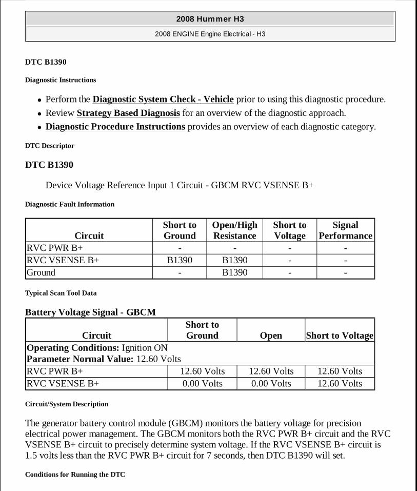
Device Voltage Reference Input 1 Circuit - GBCM RVC VSENSE B+
Diagnostic Fault Information
Typical Scan Tool Data
Battery Voltage Signal - GBCM
Circuit/System Description
The generator battery control module (GBCM) monitors the battery voltage for precision electrical power management. The GBCM monitors both the RVC PWR B+ circuit and the RVC VSENSE B+ circuit to precisely determine system voltage. If the RVC VSENSE B+ circuit is 1.5 volts less than the RVC PWR B+ circuit for 7 seconds, then DTC B1390 will set.
Conditions for Running the DTC
CircuitShort to Ground
Open/High Resistance
Short to Voltage
Signal Performance
RVC PWR B+ - - - -RVC VSENSE B+ B1390 B1390 - -Ground - B1390 - -
CircuitShort to Ground Open Short to Voltage
Operating Conditions: Ignition ON Parameter Normal Value: 12.60 VoltsRVC PWR B+ 12.60 Volts 12.60 Volts 12.60 VoltsRVC VSENSE B+ 0.00 Volts 0.00 Volts 12.60 Volts
2008 Hummer H3
2008 ENGINE Engine Electrical - H3
MY
Sunday, March 29, 2009 10:52:04 PM Page 9 © 2005 Mitchell Repair Information Company, LLC.
This diagnostic runs every 100 ms.
Conditions for Setting the DTC
The RVC VSENSE B+ circuit is 1.5 volts less than the RVC PWR B+ circuit for 7 seconds
Action Taken When the DTC Sets
� The GBCM will request the driver information center (DIC) to display the SERVICE CHARGSYS message.
� The GBCM uses the less accurate RVC PWR B+ circuit for voltage readings.
Conditions for Clearing the DTC
� During the current ignition cycle, the difference between the less precision battery positive voltage circuit reading and the high precision battery voltage sense circuit reading is less than 1.5 volts.
� The SERVICE CHARGSYS DIC message will turn off 7 seconds after the voltage on the RVC VSENSE B+ circuit returns to normal.
Diagnostic Aids
� Inspect the RVC PWR and RVC VSENSE fuses for opens. � Inspect ground G102. Verify that it is clean and tight.
Reference Information
Schematic Reference
Starting and Charging Schematics
Connector End View Reference
Component Connector End Views
Description and Operation
Charging System Description and Operation
Electrical Information Reference
� Circuit Testing
2008 Hummer H3
2008 ENGINE Engine Electrical - H3
MY
Sunday, March 29, 2009 10:52:04 PM Page 10 © 2005 Mitchell Repair Information Company, LLC.
� Connector Repairs � Testing for Intermittent Conditions and Poor Connections
� Wiring Repairs
Scan Tool Reference
Control Module References for scan tool information
Circuit/System Verification
1. Engine running, accessories OFF, measure and record the battery voltage at the battery terminals. The voltage should be between 12.6 and 15.0 volts.
� If not within the specified range, refer to Charging System Test. 2. Observe the scan tool GBCM Battery Voltage Signal parameter. The reading should be
between 12.6 and 15.0 volts.
Circuit/System Testing
1. Ignition OFF, disconnect the harness connector at the GBCM. 2. Ignition OFF, test for less than 6.5 ohms between the ground circuit terminals listed below
and ground. � Terminal H � Terminal F � If greater than the specified range, test the ground circuit for an open/high resistance.
3. Verify that a test lamp illuminates between the B+ circuit terminals listed below and ground.
� Terminal A � Terminal C � If the test lamp does not illuminate, test the B+ circuit for a short to ground or an
open/high resistance. 4. If all circuits tests normal, replace the GBCM.
Repair Procedures
Perform the Diagnostic Repair Verification after completing the diagnostic procedure.
Control Module References for GBCM replacement, setup, and programming
2008 Hummer H3
2008 ENGINE Engine Electrical - H3
MY
Sunday, March 29, 2009 10:52:04 PM Page 11 © 2005 Mitchell Repair Information Company, LLC.
DTC B1487
Diagnostic Instructions
� Perform the Diagnostic System Check - Vehicle prior to using this diagnostic procedure.
� Review Strategy Based Diagnosis for an overview of the diagnostic approach.
� Diagnostic Procedure Instructions provides an overview of each diagnostic category.
DTC Descriptor
DTC B1487
Generator L-Terminal Circuit Low - Turn On Signal Circuit
Diagnostic Fault Information
Circuit/System Description
The generator battery control module (GBCM) controls the generator through the generator turn on signal circuit, or L-Terminal circuit. The signal is a 5-volt pulse width modulation (PWM) signal of 128 hz with a duty cycle of 0-100 percent. Normal duty cycle when the engine is running is between 5-100 percent. If the generator turn on signal circuit is in the 0-5 percent range, or pulled low to ground, then DTC B1487 will set.
Conditions for Running the DTC
� The engine is running. � This diagnostic shall run every 100 ms.
Conditions for Setting the DTC
The generator turn on signal circuit is less than 5 percent duty cycle for 2 minutes.
Action Taken When the DTC Sets
� The charge indicator illuminates on the instrument panel cluster (IPC). � The driver information center (DIC) displays the SERVICE CHARGSYS message.
CircuitShort to Ground
Open/High Resistance
Short to Voltage
Signal Performance
Generator Turn On Signal B1487 - B1488 -
2008 Hummer H3
2008 ENGINE Engine Electrical - H3
MY
Sunday, March 29, 2009 10:52:04 PM Page 12 © 2005 Mitchell Repair Information Company, LLC.
Conditions for Clearing the DTC
� The DTC will pass when the generator turn on signal circuit input is greater than 5 percent duty cycle.
� The charge indicator and SERVICE CHARGSYS message will remain ON until the ignition switch is cycled after the DTC is cleared.
Reference Information
Schematic Reference
Starting and Charging Schematics
Connector End View Reference
Component Connector End Views
Description and Operation
Charging System Description and Operation
Electrical Information Reference
� Circuit Testing
� Connector Repairs � Testing for Intermittent Conditions and Poor Connections
� Wiring Repairs
Scan Tool Reference
Control Module References for scan tool information
Circuit/System Testing
1. Ignition OFF, disconnect the harness connector at the generator. 2. Ignition ON, GEN L-Terminal Signal Command 0%, test for less than 1 volt between the
generator turn on signal circuit terminal 1 X1 and ground. � If greater than the specified range, test the generator turn on signal circuit for a short to
voltage. If the circuit tests normal, replace the GBCM. 3. Command the GEN L-Terminal Signal ON to 80% duty cycle with a scan tool. Test for 3.0
2008 Hummer H3
2008 ENGINE Engine Electrical - H3
MY
Sunday, March 29, 2009 10:52:04 PM Page 13 © 2005 Mitchell Repair Information Company, LLC.
volts between the generator turn on signal circuit terminal 1 X1 and ground. � If less than the specified value, test the generator turn on signal circuit for a short to
ground, or an open/high resistance. If the circuit tests normal, replace the GBCM. 4. If the circuit tests normal, replace the generator.
Repair Procedures
Perform the Diagnostic Repair Verification after completing the diagnostic procedure.
� Generator Replacement (LH8) or Generator Replacement (LLR) � Control Module References for GBCM replacement, setup, and programming.
DTC B1488
Diagnostic Instructions
� Perform the Diagnostic System Check - Vehicle prior to using this diagnostic procedure.
� Review Strategy Based Diagnosis for an overview of the diagnostic approach.
� Diagnostic Procedure Instructions provides an overview of each diagnostic category.
DTC Descriptor
DTC B1488
Generator L-Terminal Circuit High - Turn On Signal Circuit
Diagnostic Fault Information
Circuit/System Description
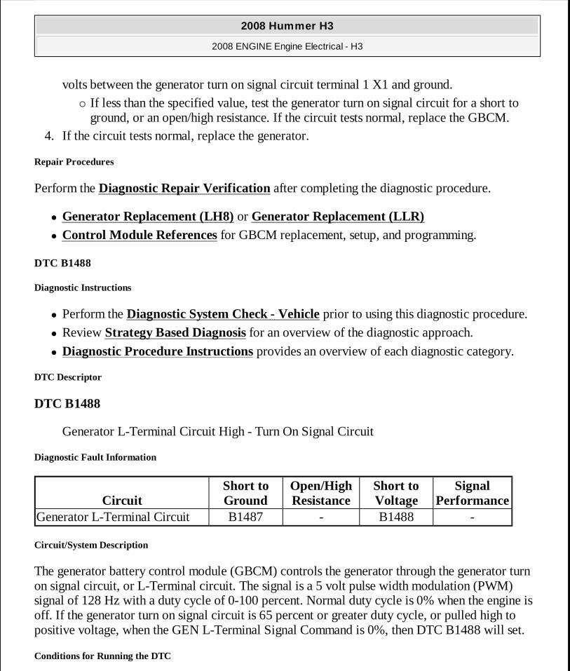
The generator battery control module (GBCM) controls the generator through the generator turn on signal circuit, or L-Terminal circuit. The signal is a 5 volt pulse width modulation (PWM) signal of 128 Hz with a duty cycle of 0-100 percent. Normal duty cycle is 0% when the engine is off. If the generator turn on signal circuit is 65 percent or greater duty cycle, or pulled high to positive voltage, when the GEN L-Terminal Signal Command is 0%, then DTC B1488 will set.
Conditions for Running the DTC
CircuitShort to Ground
Open/High Resistance
Short to Voltage
Signal Performance
Generator L-Terminal Circuit B1487 - B1488 -
2008 Hummer H3
2008 ENGINE Engine Electrical - H3
MY
Sunday, March 29, 2009 10:52:04 PM Page 14 © 2005 Mitchell Repair Information Company, LLC.
� Ignition ON. � The engine is OFF. � This diagnostic runs every 100 ms.
Conditions for Setting the DTC
The generator turn on signal circuit is greater than 65 percent or shorted to voltage for 5 seconds.
Action Taken When the DTC Sets
� The charge indicator turns ON. � The driver information center (DIC) displays the SERVICE CHARGSYS message.
Conditions for Clearing the DTC
� The GBCM determines the conditions for setting the DTC are no longer present. � The charge indicator and SERVICE CHARGSYS message turn off when the conditions for
setting the DTC are no longer present.
Reference Information
Schematic Reference
Starting and Charging Schematics
Connector End View Reference
Component Connector End Views
Description and Operation
Charging System Description and Operation
Electrical Information Reference
� Circuit Testing
� Connector Repairs � Testing for Intermittent Conditions and Poor Connections
� Wiring Repairs
Scan Tool Reference
2008 Hummer H3
2008 ENGINE Engine Electrical - H3
MY
Sunday, March 29, 2009 10:52:04 PM Page 15 © 2005 Mitchell Repair Information Company, LLC.
Control Module References for scan tool information
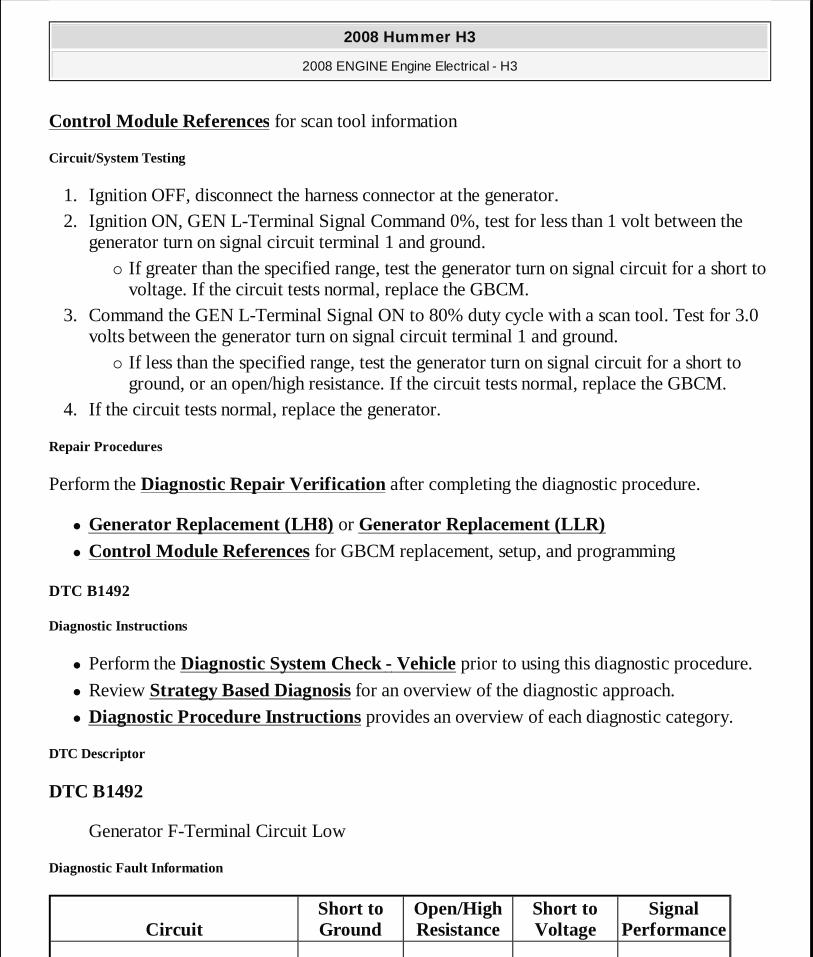
Circuit/System Testing
1. Ignition OFF, disconnect the harness connector at the generator. 2. Ignition ON, GEN L-Terminal Signal Command 0%, test for less than 1 volt between the
generator turn on signal circuit terminal 1 and ground. � If greater than the specified range, test the generator turn on signal circuit for a short to
voltage. If the circuit tests normal, replace the GBCM. 3. Command the GEN L-Terminal Signal ON to 80% duty cycle with a scan tool. Test for 3.0
volts between the generator turn on signal circuit terminal 1 and ground. � If less than the specified range, test the generator turn on signal circuit for a short to
ground, or an open/high resistance. If the circuit tests normal, replace the GBCM. 4. If the circuit tests normal, replace the generator.
Repair Procedures
Perform the Diagnostic Repair Verification after completing the diagnostic procedure.
� Generator Replacement (LH8) or Generator Replacement (LLR) � Control Module References for GBCM replacement, setup, and programming
DTC B1492
Diagnostic Instructions
� Perform the Diagnostic System Check - Vehicle prior to using this diagnostic procedure.
� Review Strategy Based Diagnosis for an overview of the diagnostic approach.
� Diagnostic Procedure Instructions provides an overview of each diagnostic category.
DTC Descriptor
DTC B1492
Generator F-Terminal Circuit Low
Diagnostic Fault Information
CircuitShort to Ground
Open/High Resistance
Short to Voltage
Signal Performance
2008 Hummer H3
2008 ENGINE Engine Electrical - H3
MY
Sunday, March 29, 2009 10:52:04 PM Page 16 © 2005 Mitchell Repair Information Company, LLC.
Typical Scan Tool Data
GEN F-Terminal Signal - ECM
Circuit/System Description
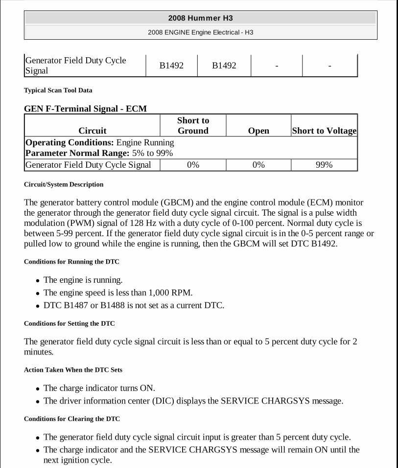
The generator battery control module (GBCM) and the engine control module (ECM) monitor the generator through the generator field duty cycle signal circuit. The signal is a pulse width modulation (PWM) signal of 128 Hz with a duty cycle of 0-100 percent. Normal duty cycle is between 5-99 percent. If the generator field duty cycle signal circuit is in the 0-5 percent range or pulled low to ground while the engine is running, then the GBCM will set DTC B1492.
Conditions for Running the DTC
� The engine is running. � The engine speed is less than 1,000 RPM. � DTC B1487 or B1488 is not set as a current DTC.
Conditions for Setting the DTC
The generator field duty cycle signal circuit is less than or equal to 5 percent duty cycle for 2 minutes.
Action Taken When the DTC Sets
� The charge indicator turns ON. � The driver information center (DIC) displays the SERVICE CHARGSYS message.
Conditions for Clearing the DTC
� The generator field duty cycle signal circuit input is greater than 5 percent duty cycle. � The charge indicator and the SERVICE CHARGSYS message will remain ON until the
next ignition cycle.
Generator Field Duty Cycle Signal
B1492 B1492 - -
CircuitShort to Ground Open Short to Voltage
Operating Conditions: Engine Running Parameter Normal Range: 5% to 99%Generator Field Duty Cycle Signal 0% 0% 99%
2008 Hummer H3
2008 ENGINE Engine Electrical - H3
MY
Sunday, March 29, 2009 10:52:04 PM Page 17 © 2005 Mitchell Repair Information Company, LLC.
Reference Information
Schematic Reference
Starting and Charging Schematics
Connector End View Reference
Component Connector End Views
Description and Operation
Charging System Description and Operation
Electrical Information Reference
� Circuit Testing
� Connector Repairs � Testing for Intermittent Conditions and Poor Connections
� Wiring Repairs
Scan Tool Reference
Control Module References for scan tool information
Circuit/System Verification
1. Engine running, observe the scan tool ECM GEN-F Terminal Signal parameter. The parameter should read between 5 and 99 percent.
� If not within the specified range, refer to Circuit/System Testing. 2. Verify that the GBCM does not set DTC B1492.
� If the GBCM sets DTC B1492, refer to Circuit/System Testing.
Circuit/System Testing
ECM Generator Field Duty Cycle Signal Circuit Malfunction
1. Ignition OFF, disconnect the harness connectors at the generator and GBCM. 2. Ignition ON, engine OFF, connect a test lamp to B+ and repeatedly probe the generator
field duty cycle circuit terminal 2 of the generator while monitoring the ECM GEN-F
2008 Hummer H3
2008 ENGINE Engine Electrical - H3
MY
Sunday, March 29, 2009 10:52:05 PM Page 18 © 2005 Mitchell Repair Information Company, LLC.
Terminal Signal parameter. The parameter should change from less than 5 percent to greater than 95 percent.
� If the parameter was not affected by the test lamp, test the circuit for a short to voltage, short to ground, or an open/high resistance. If the circuit tests normal, replace the ECM.
3. Reconnect the harness connector at the GBCM. 4. Repeatedly probe the generator field duty cycle circuit terminal 2 of the generator with the
test lamp that is connected to B+, harness side while monitoring the ECM GEN-F Terminal Signal parameter. It should change from less than 5 percent to greater than 95 percent.
� If the parameter was not affected by the test lamp, replace the GBCM. 5. If the circuit tests normal, replace the generator.
GBCM Generator Field Duty Cycle Signal Circuit Malfunction
1. Ignition OFF, disconnect the harness connector at the GBCM. 2. Ignition ON, engine OFF, connect a test lamp to B+ and repeatedly probe the generator
field duty cycle circuit terminal B of the GBCM while monitoring the ECM GEN-F Terminal Signal parameter. The parameter should change from less than 5 percent to greater than 95 percent.
� If the parameter was not affected by the test lamp, test the circuit for a short to voltage, short to ground, or an open/high resistance.
3. If the circuit tests normal, replace the GBCM.
Repair Procedures
Perform the Diagnostic Repair Verification after completing the diagnostic procedure.
� Generator Replacement (LH8) or Generator Replacement (LLR) � Control Module References for ECM or GBCM replacement, setup, and programming
DTC B1516
Diagnostic Instructions
� Perform the Diagnostic System Check - Vehicle prior to using this diagnostic procedure.
� Review Strategy Based Diagnosis for an overview of the diagnostic approach.
� Diagnostic Procedure Instructions provides an overview of each diagnostic category.
DTC Descriptor
2008 Hummer H3
2008 ENGINE Engine Electrical - H3
MY
Sunday, March 29, 2009 10:52:05 PM Page 19 © 2005 Mitchell Repair Information Company, LLC.
DTC B1516
Battery Current Sensor Performance - GBCM
Circuit/System Description
The generator battery control module (GBCM) monitors its internal battery current sensor for many charging system operations, and also for diagnostic purposes. When the values of the internal battery current sensor go out of range, DTC B1516 will set.
Conditions for Running the DTC
� The engine is running. � This diagnostic shall be run every 50 ms.
Conditions for Setting the DTC
The duty cycle of the internal battery current sensor is less than 2 percent duty cycle or greater than 98 percent duty cycle for 4 minutes.
Action Taken When the DTC Sets
� The charge indicator turns ON. � The driver information center (DIC) displays the SERVICE CHARGSYS message. � The generator field control circuit duty cycle is set to 100 percent. � The filtered battery current is set to 0.1 amp. � The battery voltage parameter defaults to 13.8 volts.
Conditions for Clearing the DTC
The duty cycle of the internal battery current sensor is greater than 2 percent duty cycle or less than 98 percent duty cycle.
Reference Information
Schematic Reference
Starting and Charging Schematics
Connector End View Reference
Component Connector End Views
2008 Hummer H3
2008 ENGINE Engine Electrical - H3
MY
Sunday, March 29, 2009 10:52:05 PM Page 20 © 2005 Mitchell Repair Information Company, LLC.
Description and Operation
Charging System Description and Operation
Electrical Information Reference
� Circuit Testing
� Connector Repairs � Testing for Intermittent Conditions and Poor Connections
� Wiring Repairs
Scan Tool Reference
Control Module References for scan tool information
Circuit/System Verification
Ignition ON, clear the DTC and start the engine. Verify DTC B1516 does not set as current.
� If the DTC sets, replace the GBCM.
Repair Procedures
Perform the Diagnostic Repair Verification after completing the diagnostic procedure.
Control Module References for GBCM replacement, setup, and programming
DTC B151B
Diagnostic Instructions
� Perform the Diagnostic System Check - Vehicle prior to using this diagnostic procedure.
� Review Strategy Based Diagnosis for an overview of the diagnostic approach.
� Diagnostic Procedure Instructions provides an overview of each diagnostic category.
DTC Descriptors
DTC B151B
Current Sensor Polarity Error - GBCM
Circuit/System Description
2008 Hummer H3
2008 ENGINE Engine Electrical - H3
MY
Sunday, March 29, 2009 10:52:05 PM Page 21 © 2005 Mitchell Repair Information Company, LLC.
The generator battery control module (GBCM) monitors its internal battery current sensor for many charging system operations, and also for diagnostic purposes. If reversed polarity of the battery current is sensed, then DTC B151B will set.
Conditions for Running the DTC
� The engine is not running. � DTC B1516 is not set.
Conditions for Setting the DTC
The GBCM detects positive battery current.
Action Taken When the DTC Sets
The regulated voltage control (RVC) is disabled.
Conditions for Clearing the DTC
The GBCM detects correct polarity of the battery current.
Diagnostic Aids
DTC B151B may set if a battery charger is used.
Reference Information
Schematic Reference
Starting and Charging Schematics
Connector End View Reference
Component Connector End Views
Description and Operation
Charging System Description and Operation
Electrical Information Reference
� Circuit Testing
� Connector Repairs
2008 Hummer H3
2008 ENGINE Engine Electrical - H3
MY
Sunday, March 29, 2009 10:52:05 PM Page 22 © 2005 Mitchell Repair Information Company, LLC.
� Testing for Intermittent Conditions and Poor Connections
� Wiring Repairs
Scan Tool Reference
Control Module References for scan tool information
Circuit/System Verification
1. Verify that the GBCM is installed correctly. The GBCM should be installed on the negative battery cables, with the sensor coil around the negative cables and facing away from the battery, and with the harness connector facing toward the battery.
� If the GBCM is installed backwards or incorrectly, remove and reinstall the GBCM. 2. Ignition ON, clear the DTC with the scan tool. Verify that DTC B151B does not set.
� If the DTC sets, replace the GBCM.
Repair Procedures
Perform the Diagnostic Repair Verification after completing the diagnostic procedure.
Control Module References for GBCM replacement, setup, and programming.
DTC B1566
Diagnostic Instructions
� Perform the Diagnostic System Check - Vehicle prior to using this diagnostic procedure.
� Review Strategy Based Diagnosis for an overview of the diagnostic approach.
� Diagnostic Procedure Instructions provides an overview of each diagnostic category.
DTC Descriptors
DTC B1566
Current Sensor Polarity Check - GBCM
Circuit/System Description
The generator battery control module (GBCM) monitors its internal battery current sensor for many charging system operations, and also for diagnostic purposes. If reversed polarity of the battery current is sensed, then DTC B1566 will set.
2008 Hummer H3
2008 ENGINE Engine Electrical - H3
MY
Sunday, March 29, 2009 10:52:05 PM Page 23 © 2005 Mitchell Repair Information Company, LLC.
Conditions for Running the DTC
� The engine is running. � This diagnostic runs every 50 ms.
Conditions for Setting the DTC
The GBCM detects reverse polarity of the battery current.
Action Taken When the DTC Sets
� The charge indicator turns ON. � The driver information center (DIC) displays the SERVICE CHARGSYS message. � The filtered battery current is set to 0.1 amp. � The generator field control circuit duty cycle is set to 100 percent, battery voltage defaults
to 13.8 volts.
Conditions for Clearing the DTC
The GBCM detects correct polarity of the battery current.
Reference Information
Schematic Reference
Starting and Charging Schematics
Connector End View Reference
Component Connector End Views
Description and Operation
Charging System Description and Operation
Electrical Information Reference
� Circuit Testing
� Connector Repairs � Testing for Intermittent Conditions and Poor Connections
� Wiring Repairs
2008 Hummer H3
2008 ENGINE Engine Electrical - H3
MY
Sunday, March 29, 2009 10:52:05 PM Page 24 © 2005 Mitchell Repair Information Company, LLC.
Scan Tool Reference
Control Module References for scan tool information
Circuit/System Verification
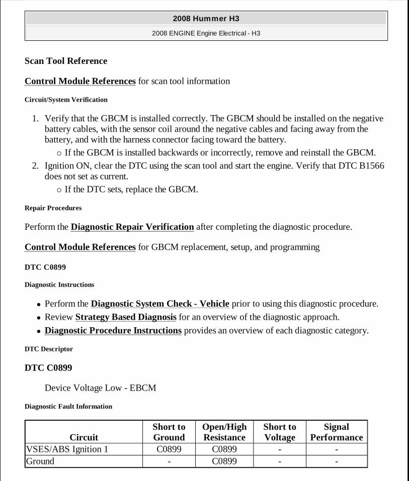
1. Verify that the GBCM is installed correctly. The GBCM should be installed on the negative battery cables, with the sensor coil around the negative cables and facing away from the battery, and with the harness connector facing toward the battery.
� If the GBCM is installed backwards or incorrectly, remove and reinstall the GBCM. 2. Ignition ON, clear the DTC using the scan tool and start the engine. Verify that DTC B1566
does not set as current. � If the DTC sets, replace the GBCM.
Repair Procedures
Perform the Diagnostic Repair Verification after completing the diagnostic procedure.
Control Module References for GBCM replacement, setup, and programming
DTC C0899
Diagnostic Instructions
� Perform the Diagnostic System Check - Vehicle prior to using this diagnostic procedure.
� Review Strategy Based Diagnosis for an overview of the diagnostic approach.
� Diagnostic Procedure Instructions provides an overview of each diagnostic category.
DTC Descriptor
DTC C0899
Device Voltage Low - EBCM
Diagnostic Fault Information
CircuitShort to Ground
Open/High Resistance
Short to Voltage
Signal Performance
VSES/ABS Ignition 1 C0899 C0899 - -Ground - C0899 - -
2008 Hummer H3
2008 ENGINE Engine Electrical - H3
MY
Sunday, March 29, 2009 10:52:05 PM Page 25 © 2005 Mitchell Repair Information Company, LLC.
Typical Scan Tool Data
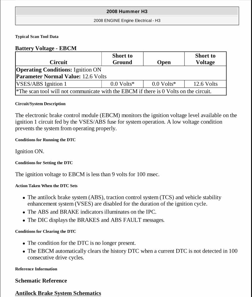
Battery Voltage - EBCM
Circuit/System Description
The electronic brake control module (EBCM) monitors the ignition voltage level available on the ignition 1 circuit fed by the VSES/ABS fuse for system operation. A low voltage condition prevents the system from operating properly.
Conditions for Running the DTC
Ignition ON.
Conditions for Setting the DTC
The ignition voltage to EBCM is less than 9 volts for 100 msec.
Action Taken When the DTC Sets
� The antilock brake system (ABS), traction control system (TCS) and vehicle stability enhancement system (VSES) are disabled for the duration of the ignition cycle.
� The ABS and BRAKE indicators illuminates on the IPC. � The DIC displays the BRAKES and ABS FAULT messages.
Conditions for Clearing the DTC
� The condition for the DTC is no longer present. � The EBCM automatically clears the history DTC when a current DTC is not detected in 100
consecutive drive cycles.
Reference Information
Schematic Reference
Antilock Brake System Schematics
CircuitShort to Ground Open
Short to Voltage
Operating Conditions: Ignition ON Parameter Normal Value: 12.6 VoltsVSES/ABS Ignition 1 0.0 Volts* 0.0 Volts* 12.6 Volts*The scan tool will not communicate with the EBCM if there is 0 Volts on the circuit.
2008 Hummer H3
2008 ENGINE Engine Electrical - H3
MY
Sunday, March 29, 2009 10:52:05 PM Page 26 © 2005 Mitchell Repair Information Company, LLC.
Connector End View Reference
Component Connector End Views
Description and Operation
Charging System Description and Operation
Electrical Information Reference
� Circuit Testing
� Connector Repairs � Testing for Intermittent Conditions and Poor Connections
� Wiring Repairs
Scan Tool Reference
Control Module References for scan tool information
Circuit/System Verification
1. Engine running, accessories OFF, measure and record the battery voltage at the battery terminals. The voltage should be between 12.6 and 15.0 volts.
� If not within the specified range, refer to Charging System Test. 2. Observe the scan tool EBCM Battery Voltage parameter. The reading should be between
12.6 and 15.0 volts.
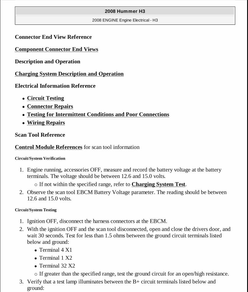
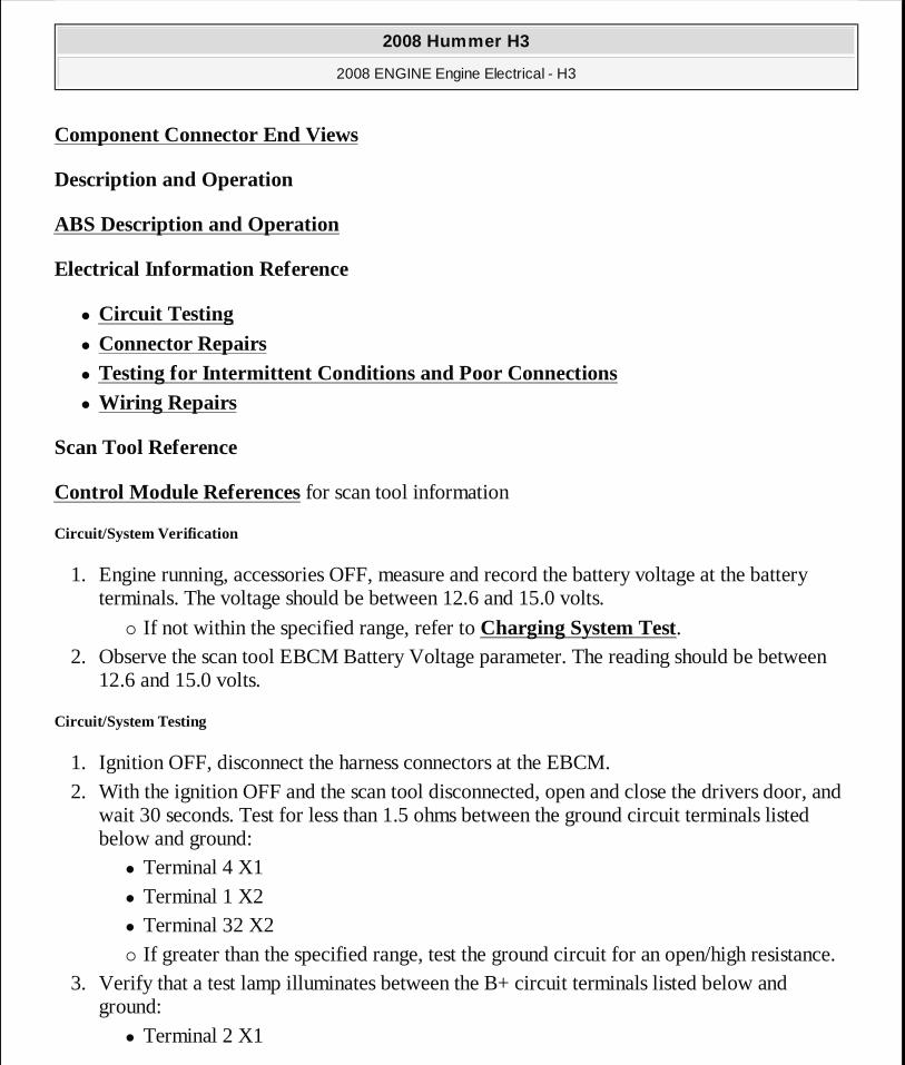
Circuit/System Testing
1. Ignition OFF, disconnect the harness connectors at the EBCM. 2. With the ignition OFF and the scan tool disconnected, open and close the drivers door, and
wait 30 seconds. Test for less than 1.5 ohms between the ground circuit terminals listed below and ground:
� Terminal 4 X1 � Terminal 1 X2 � Terminal 32 X2 � If greater than the specified range, test the ground circuit for an open/high resistance.
3. Verify that a test lamp illuminates between the B+ circuit terminals listed below and ground:
2008 Hummer H3
2008 ENGINE Engine Electrical - H3
MY
Sunday, March 29, 2009 10:52:05 PM Page 27 © 2005 Mitchell Repair Information Company, LLC.
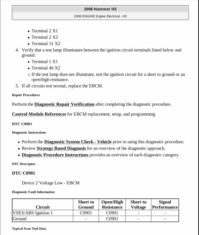
� Terminal 2 X1 � Terminal 2 X2 � Terminal 31 X2
4. Verify that a test lamp illuminates between the ignition circuit terminals listed below and ground:
� Terminal 1 X1 � Terminal 46 X2 � If the test lamp does not illuminate, test the ignition circuit for a short to ground or an
open/high resistance. 5. If all circuits test normal, replace the EBCM.
Repair Procedures
Perform the Diagnostic Repair Verification after completing the diagnostic procedure.
Control Module References for EBCM replacement, setup, and programming
DTC C0901
Diagnostic Instructions
� Perform the Diagnostic System Check - Vehicle prior to using this diagnostic procedure.
� Review Strategy Based Diagnosis for an overview of the diagnostic approach.
� Diagnostic Procedure Instructions provides an overview of each diagnostic category.
DTC Descriptor
DTC C0901
Device 2 Voltage Low - EBCM
Diagnostic Fault Information
Typical Scan Tool Data
CircuitShort to Ground
Open/High Resistance
Short to Voltage
Signal Performance
VSES/ABS Ignition 1 C0901 C0901 - -Ground - C0901 - -
2008 Hummer H3
2008 ENGINE Engine Electrical - H3
MY
Sunday, March 29, 2009 10:52:05 PM Page 28 © 2005 Mitchell Repair Information Company, LLC.
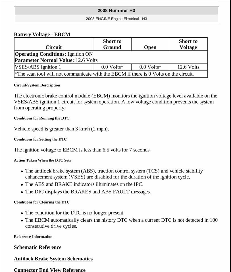
Battery Voltage - EBCM
Circuit/System Description
The electronic brake control module (EBCM) monitors the ignition voltage level available on the VSES/ABS ignition 1 circuit for system operation. A low voltage condition prevents the system from operating properly.
Conditions for Running the DTC
Vehicle speed is greater than 3 km/h (2 mph).
Conditions for Setting the DTC
The ignition voltage to EBCM is less than 6.5 volts for 7 seconds.
Action Taken When the DTC Sets
� The antilock brake system (ABS), traction control system (TCS) and vehicle stability enhancement system (VSES) are disabled for the duration of the ignition cycle.
� The ABS and BRAKE indicators illuminates on the IPC. � The DIC displays the BRAKES and ABS FAULT messages.
Conditions for Clearing the DTC
� The condition for the DTC is no longer present. � The EBCM automatically clears the history DTC when a current DTC is not detected in 100
consecutive drive cycles.
Reference Information
Schematic Reference
Antilock Brake System Schematics
Connector End View Reference
CircuitShort to Ground Open
Short to Voltage
Operating Conditions: Ignition ON Parameter Normal Value: 12.6 VoltsVSES/ABS Ignition 1 0.0 Volts* 0.0 Volts* 12.6 Volts*The scan tool will not communicate with the EBCM if there is 0 Volts on the circuit.
2008 Hummer H3
2008 ENGINE Engine Electrical - H3
MY
Sunday, March 29, 2009 10:52:05 PM Page 29 © 2005 Mitchell Repair Information Company, LLC.
Component Connector End Views
Description and Operation
ABS Description and Operation
Electrical Information Reference
� Circuit Testing
� Connector Repairs � Testing for Intermittent Conditions and Poor Connections
� Wiring Repairs
Scan Tool Reference
Control Module References for scan tool information
Circuit/System Verification
1. Engine running, accessories OFF, measure and record the battery voltage at the battery terminals. The voltage should be between 12.6 and 15.0 volts.
� If not within the specified range, refer to Charging System Test. 2. Observe the scan tool EBCM Battery Voltage parameter. The reading should be between
12.6 and 15.0 volts.
Circuit/System Testing
1. Ignition OFF, disconnect the harness connectors at the EBCM. 2. With the ignition OFF and the scan tool disconnected, open and close the drivers door, and
wait 30 seconds. Test for less than 1.5 ohms between the ground circuit terminals listed below and ground:
� Terminal 4 X1 � Terminal 1 X2 � Terminal 32 X2 � If greater than the specified range, test the ground circuit for an open/high resistance.
3. Verify that a test lamp illuminates between the B+ circuit terminals listed below and ground:
� Terminal 2 X1
2008 Hummer H3
2008 ENGINE Engine Electrical - H3
MY
Sunday, March 29, 2009 10:52:05 PM Page 30 © 2005 Mitchell Repair Information Company, LLC.
� Terminal 2 X2 � Terminal 31 X2
4. Verify that a test lamp illuminates between the ignition circuit terminals listed below and ground:
� Terminal 1 X1 � Terminal 46 X2 � If the test lamp does not illuminate, test the ignition circuit for a short to ground or an
open/high resistance. 5. If all circuits test normal, replace the EBCM.
Repair Procedures
Perform the Diagnostic Repair Verification after completing the diagnostic procedure.
Control Module References for EBCM replacement, setup, and programming
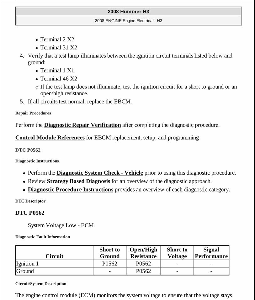
DTC P0562
Diagnostic Instructions
� Perform the Diagnostic System Check - Vehicle prior to using this diagnostic procedure.
� Review Strategy Based Diagnosis for an overview of the diagnostic approach.
� Diagnostic Procedure Instructions provides an overview of each diagnostic category.
DTC Descriptor
DTC P0562
System Voltage Low - ECM
Diagnostic Fault Information
Circuit/System Description
The engine control module (ECM) monitors the system voltage to ensure that the voltage stays
CircuitShort to Ground
Open/High Resistance
Short to Voltage
Signal Performance
Ignition 1 P0562 P0562 - -Ground - P0562 - -
2008 Hummer H3
2008 ENGINE Engine Electrical - H3
MY
Sunday, March 29, 2009 10:52:05 PM Page 31 © 2005 Mitchell Repair Information Company, LLC.
within the proper range. Damage to components, and incorrect data may occur when the voltage is out of range.
Conditions for Running the DTC
� The vehicle speed is above 8 km/h (5 mph). � The system voltage is between 9.5-18 volts.
Conditions for Setting the DTC
The ECM detects a system voltage less than 10 volts for 5 seconds.
Action Taken When the DTC Sets
DTC P0562 is a C type DTC.
Conditions for Clearing the DTC
DTC P0562 is a C type DTC.
Diagnostic Aids
A low voltage DTC in multiple modules indicates a concern with the charging system.
Reference Information
Schematic Reference
Starting and Charging Schematics
Connector End View Reference
Component Connector End Views
Description and Operation
Charging System Description and Operation
Electrical Information Reference
� Circuit Testing
� Connector Repairs � Testing for Intermittent Conditions and Poor Connections
2008 Hummer H3
2008 ENGINE Engine Electrical - H3
MY
Sunday, March 29, 2009 10:52:05 PM Page 32 © 2005 Mitchell Repair Information Company, LLC.
� Wiring Repairs
Scan Tool Reference
Control Module References for scan tool information
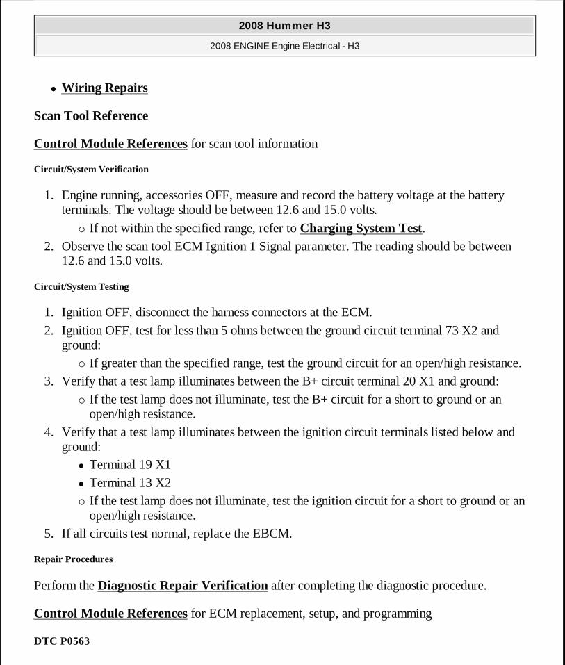
Circuit/System Verification
1. Engine running, accessories OFF, measure and record the battery voltage at the battery terminals. The voltage should be between 12.6 and 15.0 volts.
� If not within the specified range, refer to Charging System Test. 2. Observe the scan tool ECM Ignition 1 Signal parameter. The reading should be between
12.6 and 15.0 volts.
Circuit/System Testing
1. Ignition OFF, disconnect the harness connectors at the ECM. 2. Ignition OFF, test for less than 5 ohms between the ground circuit terminal 73 X2 and
ground: � If greater than the specified range, test the ground circuit for an open/high resistance.
3. Verify that a test lamp illuminates between the B+ circuit terminal 20 X1 and ground: � If the test lamp does not illuminate, test the B+ circuit for a short to ground or an
open/high resistance. 4. Verify that a test lamp illuminates between the ignition circuit terminals listed below and
ground: � Terminal 19 X1 � Terminal 13 X2 � If the test lamp does not illuminate, test the ignition circuit for a short to ground or an
open/high resistance. 5. If all circuits test normal, replace the EBCM.
Repair Procedures
Perform the Diagnostic Repair Verification after completing the diagnostic procedure.
Control Module References for ECM replacement, setup, and programming
DTC P0563
2008 Hummer H3
2008 ENGINE Engine Electrical - H3
MY
Sunday, March 29, 2009 10:52:05 PM Page 33 © 2005 Mitchell Repair Information Company, LLC.
Diagnostic Instructions
� Perform the Diagnostic System Check - Vehicle prior to using this diagnostic procedure.
� Review Strategy Based Diagnosis for an overview of the diagnostic approach.
� Diagnostic Procedure Instructions provides an overview of each diagnostic category.
DTC Descriptor
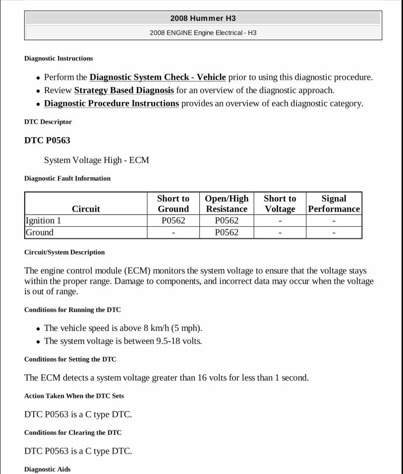
DTC P0563
System Voltage High - ECM
Diagnostic Fault Information
Circuit/System Description
The engine control module (ECM) monitors the system voltage to ensure that the voltage stays within the proper range. Damage to components, and incorrect data may occur when the voltage is out of range.
Conditions for Running the DTC
� The vehicle speed is above 8 km/h (5 mph). � The system voltage is between 9.5-18 volts.
Conditions for Setting the DTC
The ECM detects a system voltage greater than 16 volts for less than 1 second.
Action Taken When the DTC Sets
DTC P0563 is a C type DTC.
Conditions for Clearing the DTC
DTC P0563 is a C type DTC.
Diagnostic Aids
CircuitShort to Ground
Open/High Resistance
Short to Voltage
Signal Performance
Ignition 1 P0562 P0562 - -Ground - P0562 - -
2008 Hummer H3
2008 ENGINE Engine Electrical - H3
MY
Sunday, March 29, 2009 10:52:05 PM Page 34 © 2005 Mitchell Repair Information Company, LLC.
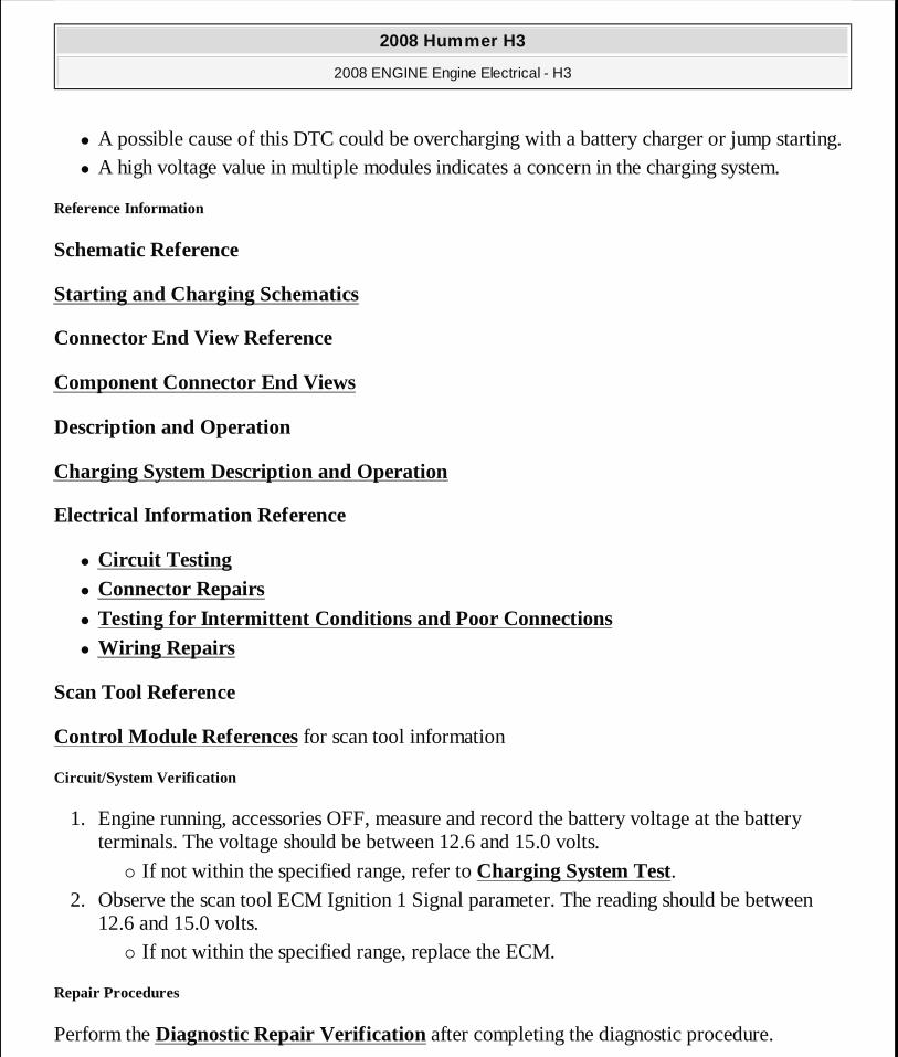
� A possible cause of this DTC could be overcharging with a battery charger or jump starting. � A high voltage value in multiple modules indicates a concern in the charging system.
Reference Information
Schematic Reference
Starting and Charging Schematics
Connector End View Reference
Component Connector End Views
Description and Operation
Charging System Description and Operation
Electrical Information Reference
� Circuit Testing
� Connector Repairs � Testing for Intermittent Conditions and Poor Connections
� Wiring Repairs
Scan Tool Reference
Control Module References for scan tool information
Circuit/System Verification
1. Engine running, accessories OFF, measure and record the battery voltage at the battery terminals. The voltage should be between 12.6 and 15.0 volts.
� If not within the specified range, refer to Charging System Test. 2. Observe the scan tool ECM Ignition 1 Signal parameter. The reading should be between
12.6 and 15.0 volts. � If not within the specified range, replace the ECM.
Repair Procedures
Perform the Diagnostic Repair Verification after completing the diagnostic procedure.
2008 Hummer H3
2008 ENGINE Engine Electrical - H3
MY
Sunday, March 29, 2009 10:52:05 PM Page 35 © 2005 Mitchell Repair Information Company, LLC.
Control Module References for ECM replacement, setup, and programming
DTC P0615
Diagnostic Instructions
� Perform the Diagnostic System Check - Vehicle prior to using this diagnostic procedure.
� Review Strategy Based Diagnosis for an overview of the diagnostic approach.
� Diagnostic Procedure Instructions provides an overview of each diagnostic category.
DTC Descriptor
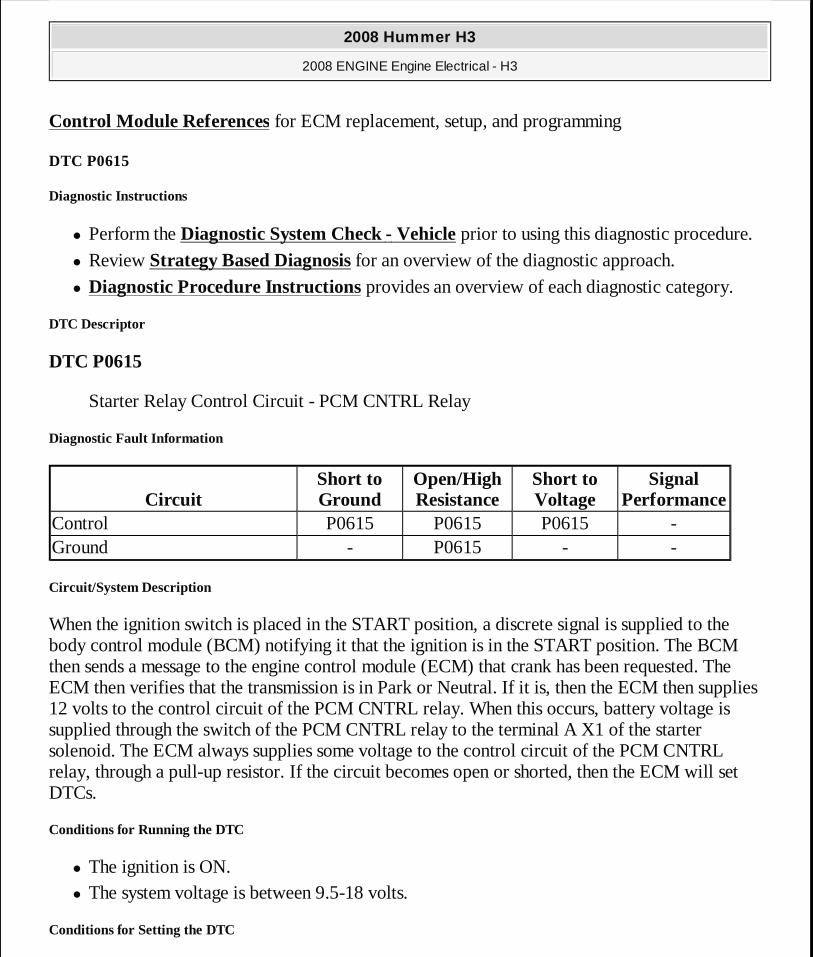
DTC P0615
Starter Relay Control Circuit - PCM CNTRL Relay
Diagnostic Fault Information
Circuit/System Description
When the ignition switch is placed in the START position, a discrete signal is supplied to the body control module (BCM) notifying it that the ignition is in the START position. The BCM then sends a message to the engine control module (ECM) that crank has been requested. The ECM then verifies that the transmission is in Park or Neutral. If it is, then the ECM then supplies 12 volts to the control circuit of the PCM CNTRL relay. When this occurs, battery voltage is supplied through the switch of the PCM CNTRL relay to the terminal A X1 of the starter solenoid. The ECM always supplies some voltage to the control circuit of the PCM CNTRL relay, through a pull-up resistor. If the circuit becomes open or shorted, then the ECM will set DTCs.
Conditions for Running the DTC
� The ignition is ON. � The system voltage is between 9.5-18 volts.
Conditions for Setting the DTC
CircuitShort to Ground
Open/High Resistance
Short to Voltage
Signal Performance
Control P0615 P0615 P0615 -Ground - P0615 - -
2008 Hummer H3
2008 ENGINE Engine Electrical - H3
MY
Sunday, March 29, 2009 10:52:05 PM Page 36 © 2005 Mitchell Repair Information Company, LLC.
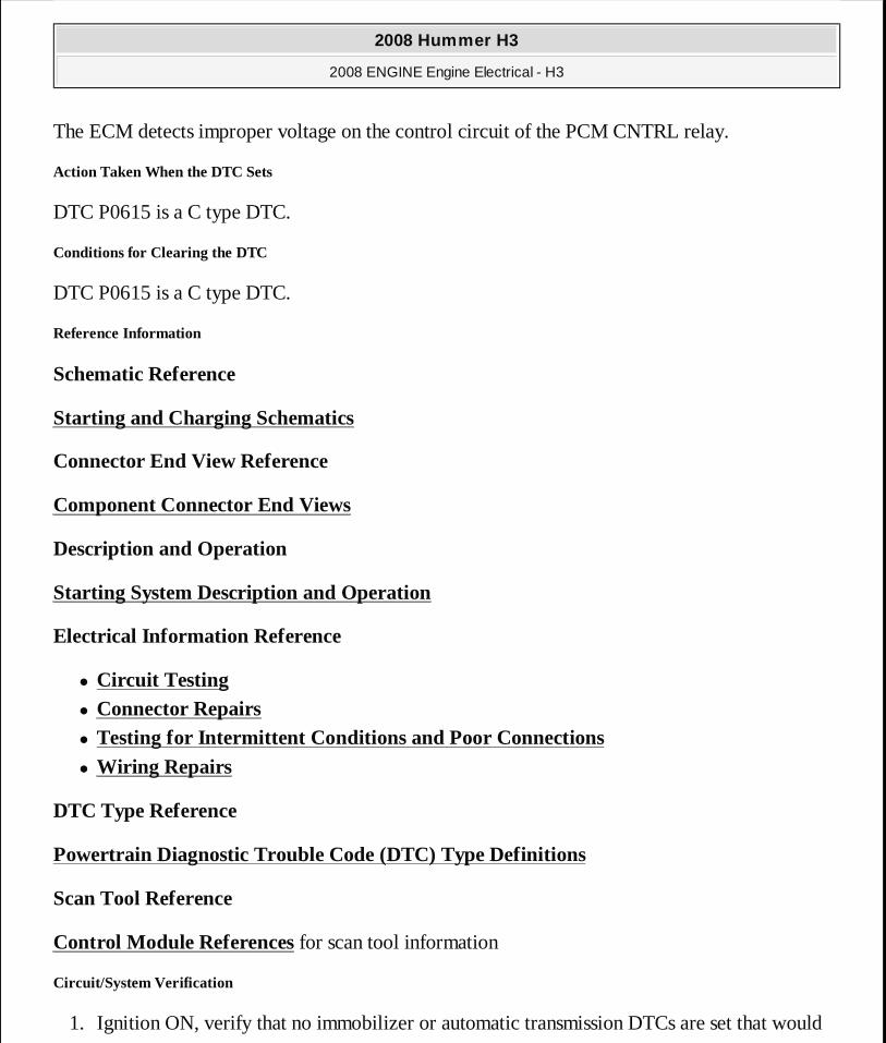
The ECM detects improper voltage on the control circuit of the PCM CNTRL relay.
Action Taken When the DTC Sets
DTC P0615 is a C type DTC.
Conditions for Clearing the DTC
DTC P0615 is a C type DTC.
Reference Information
Schematic Reference
Starting and Charging Schematics
Connector End View Reference
Component Connector End Views
Description and Operation
Starting System Description and Operation
Electrical Information Reference
� Circuit Testing
� Connector Repairs � Testing for Intermittent Conditions and Poor Connections
� Wiring Repairs
DTC Type Reference
Powertrain Diagnostic Trouble Code (DTC) Type Definitions
Scan Tool Reference
Control Module References for scan tool information
Circuit/System Verification
1. Ignition ON, verify that no immobilizer or automatic transmission DTCs are set that would
2008 Hummer H3
2008 ENGINE Engine Electrical - H3
MY
Sunday, March 29, 2009 10:52:05 PM Page 37 © 2005 Mitchell Repair Information Company, LLC.
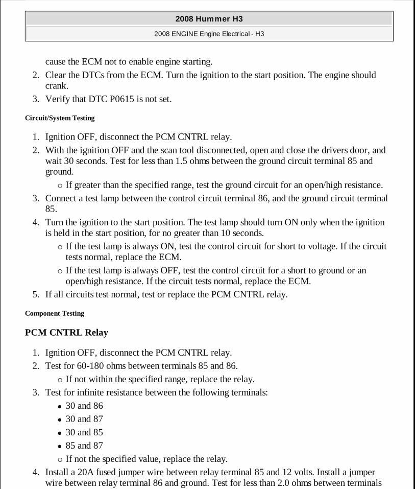
cause the ECM not to enable engine starting. 2. Clear the DTCs from the ECM. Turn the ignition to the start position. The engine should
crank. 3. Verify that DTC P0615 is not set.
Circuit/System Testing
1. Ignition OFF, disconnect the PCM CNTRL relay. 2. With the ignition OFF and the scan tool disconnected, open and close the drivers door, and
wait 30 seconds. Test for less than 1.5 ohms between the ground circuit terminal 85 and ground.
� If greater than the specified range, test the ground circuit for an open/high resistance. 3. Connect a test lamp between the control circuit terminal 86, and the ground circuit terminal
85. 4. Turn the ignition to the start position. The test lamp should turn ON only when the ignition
is held in the start position, for no greater than 10 seconds. � If the test lamp is always ON, test the control circuit for short to voltage. If the circuit
tests normal, replace the ECM. � If the test lamp is always OFF, test the control circuit for a short to ground or an
open/high resistance. If the circuit tests normal, replace the ECM. 5. If all circuits test normal, test or replace the PCM CNTRL relay.
Component Testing
PCM CNTRL Relay
1. Ignition OFF, disconnect the PCM CNTRL relay. 2. Test for 60-180 ohms between terminals 85 and 86.
� If not within the specified range, replace the relay. 3. Test for infinite resistance between the following terminals:
� 30 and 86 � 30 and 87 � 30 and 85 � 85 and 87 � If not the specified value, replace the relay.
4. Install a 20A fused jumper wire between relay terminal 85 and 12 volts. Install a jumper wire between relay terminal 86 and ground. Test for less than 2.0 ohms between terminals
2008 Hummer H3
2008 ENGINE Engine Electrical - H3
MY
Sunday, March 29, 2009 10:52:05 PM Page 38 © 2005 Mitchell Repair Information Company, LLC.
30 and 87. � If greater than specified range, replace the relay.
Repair Procedures
Perform the Diagnostic Repair Verification after completing the diagnostic procedure.
� Relay Replacement (Attached to Wire Harness) or Relay Replacement (Within an Electrical Center)
� Control Module References for ECM replacement, setup, and programming
SYMPTOMS - ENGINE ELECTRICAL
� Perform Control Module References before using the Symptom Tables in order to verify that all of the following are true:
� There are no DTCs set. � The control modules can communicate via the serial data link.
� Review the system descriptions and operations in order to familiarize yourself with the system functions. Refer to one of the following system operations:
� Battery Description and Operation � Charging System Description and Operation � Electrical Power Management Description and Operation
� Starting System Description and Operation
Visual/Physical Inspection
� Inspect for aftermarket devices which could affect the operation of the starting and charging systems. Refer to Checking Aftermarket Accessories .
� Inspect the easily accessible or visible system components for obvious damage or conditions which could cause the symptom.
Intermittent
Faulty electrical connections or wiring may be the cause of intermittent conditions. Refer to Testing for Intermittent Conditions and Poor Connections .
IMPORTANT: The following steps must be completed before using the symptom tables.
2008 Hummer H3
2008 ENGINE Engine Electrical - H3
MY
Sunday, March 29, 2009 10:52:05 PM Page 39 © 2005 Mitchell Repair Information Company, LLC.
Symptom List
Refer to a symptom diagnostic procedure from the following list in order to diagnose the symptom:
� Battery Inspection/Test � Battery Electrical Drain/Parasitic Load Test � Battery Common Causes of Malfunction � Charging System Test � Generator Noise Diagnosis � Starter Solenoid Does Not Click (Automatic M30) or Starter Solenoid Does Not Click
(Manual MA5)
� Starter Solenoid Clicks, Engine Does Not Crank � Engine Cranks Slowly � Starter Motor Noise Diagnosis
BATTERY INSPECTION/TEST
Special Tools
J 42000 Battery Tester. See Special Tools.
Diagnostic Aids
Follow these instructions in order to avoid an incorrect diagnosis because of connections:
� If testing the vehicle with the battery cables still connected, wiggle the J 42000 clips on the terminal bolt. See Special Tools. This may cut through any coating or through any
CAUTION: Refer to Battery Disconnect Caution .
IMPORTANT:� The battery test using the J 42000 Battery Tester r equires
correct connections to the battery terminals. See S pecial Tools . A failure to obtain the correct connections durin g the test may result in a failed test on a good battery.
� Use the Out of Vehicle test for each battery when t esting a vehicle with dual batteries.
2008 Hummer H3
2008 ENGINE Engine Electrical - H3
MY
Sunday, March 29, 2009 10:52:05 PM Page 40 © 2005 Mitchell Repair Information Company, LLC.
oxidation that may be present on the bolt.
Even new bolts contain a protective coating that may insulate or cause a resistance in the test circuit.
� If correct connections to the battery terminal bolts in the vehicle are in doubt, perform the following steps:
1. Disconnect the negative battery cable. 2. Disconnect the positive battery cable. 3. Install the test adapters on the terminals. 4. Follow the instructions for testing a removed battery.
� If the tester displays a REPLACE BATTERY or BAD CELL-REPLACE result for a battery tested in the vehicle with the battery cables connected, perform the following steps:
1. Disconnect the negative battery cable. 2. Disconnect the positive battery cable. 3. Install the tester adapters.
4. Follow the instructions for testing a removed battery. 5. Replace the battery only if the second test shows a REPLACE BATTERY or BAD
CELL-REPLACE result.
Use the test code from the second test for any warranty purposes.
� Use the correct terminal adapters.
Do not use any common bolts or a combination of bolts, of nuts, and of washers as adapters when testing the battery.
Use the test adapters that are provided with the J 42000 or GM P/N 12303040 terminal adapters. See Special Tools. If the adapters that are provided with the J 42000 require
IMPORTANT: Always write the test code displayed by t he tester on the repair order for any warranty purposes. The number is a unique code that describes the test data for a part icular battery at a particular time. The test code may occasionally repeat when you retest the same batter y. More often, each test will result in a different co de. Use the test code from the second, or Out of Vehicle te st.
2008 Hummer H3
2008 ENGINE Engine Electrical - H3
MY
Sunday, March 29, 2009 10:52:05 PM Page 41 © 2005 Mitchell Repair Information Company, LLC.
replacement, use GM P/N 12303040. See Special Tools. Any other adapter may not contact the correct areas of the battery terminal, causing a resistance that may result in an invalid battery test result.
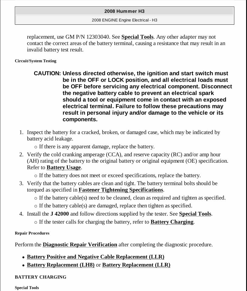
Circuit/System Testing
1. Inspect the battery for a cracked, broken, or damaged case, which may be indicated by battery acid leakage.
� If there is any apparent damage, replace the battery. 2. Verify the cold cranking amperage (CCA), and reserve capacity (RC) and/or amp hour
(AH) rating of the battery to the original battery or original equipment (OE) specification. Refer to Battery Usage.
� If the battery does not meet or exceed specifications, replace the battery. 3. Verify that the battery cables are clean and tight. The battery terminal bolts should be
torqued as specified in Fastener Tightening Specifications. � If the battery cable(s) need to be cleaned, clean as required and tighten as specified. � If the battery cable(s) are damaged, replace then tighten as specified.
4. Install the J 42000 and follow directions supplied by the tester. See Special Tools. � If the tester calls for charging the battery, refer to Battery Charging.
Repair Procedures
Perform the Diagnostic Repair Verification after completing the diagnostic procedure.
� Battery Positive and Negative Cable Replacement (LLR) � Battery Replacement (LH8) or Battery Replacement (LLR)
BATTERY CHARGING
Special Tools
CAUTION: Unless directed otherwise, the ignition and start switch must be in the OFF or LOCK position, and all electrical loads must be OFF before servicing any electrical component. D isconnect the negative battery cable to prevent an electrical spark should a tool or equipment come in contact with an exposed electrical terminal. Failure to follow these precau tions may result in personal injury and/or damage to the vehi cle or its components.
2008 Hummer H3
2008 ENGINE Engine Electrical - H3
MY
Sunday, March 29, 2009 10:52:05 PM Page 42 © 2005 Mitchell Repair Information Company, LLC.
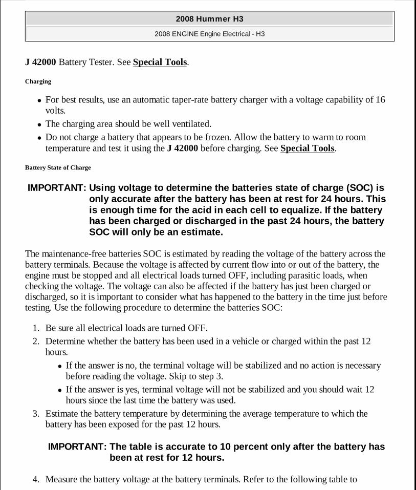
J 42000 Battery Tester. See Special Tools.
Charging
� For best results, use an automatic taper-rate battery charger with a voltage capability of 16 volts.
� The charging area should be well ventilated. � Do not charge a battery that appears to be frozen. Allow the battery to warm to room
temperature and test it using the J 42000 before charging. See Special Tools.
Battery State of Charge
The maintenance-free batteries SOC is estimated by reading the voltage of the battery across the battery terminals. Because the voltage is affected by current flow into or out of the battery, the engine must be stopped and all electrical loads turned OFF, including parasitic loads, when checking the voltage. The voltage can also be affected if the battery has just been charged or discharged, so it is important to consider what has happened to the battery in the time just before testing. Use the following procedure to determine the batteries SOC:
1. Be sure all electrical loads are turned OFF. 2. Determine whether the battery has been used in a vehicle or charged within the past 12
hours. � If the answer is no, the terminal voltage will be stabilized and no action is necessary
before reading the voltage. Skip to step 3. � If the answer is yes, terminal voltage will not be stabilized and you should wait 12
hours since the last time the battery was used. 3. Estimate the battery temperature by determining the average temperature to which the
battery has been exposed for the past 12 hours.
4. Measure the battery voltage at the battery terminals. Refer to the following table to
IMPORTANT: Using voltage to determine the batteries state of charge (SOC) is only accurate after the battery has been at rest fo r 24 hours. This is enough time for the acid in each cell to equaliz e. If the battery has been charged or discharged in the past 24 hours , the battery SOC will only be an estimate.
IMPORTANT: The table is accurate to 10 percent only after the battery has been at rest for 12 hours.
2008 Hummer H3
2008 ENGINE Engine Electrical - H3
MY
Sunday, March 29, 2009 10:52:05 PM Page 43 © 2005 Mitchell Repair Information Company, LLC.

determine the SOC according to the estimated battery temperature:
Use the SOC information as follows:
� A battery with a SOC that is below 65 percent must always be recharged before returning it to service or continuing storage.
� A battery with a SOC that is 65 percent or greater is generally considered to be charged enough in order to be returned to normal service or in order to continue storage. However, if the battery is being used in slow traffic or with short drive times, or if the temperature is very hot or very cold, the battery should be fully charged, to at least 90 percent, before returning it to service or continuing storage.
Charging Time Required
The time required to charge a battery will vary depending upon the following factors:
� The battery charger capacity-The higher the charger amperage, the less time it will take to charge the battery.
� The SOC of the battery-A completely discharged battery requires more than twice as much charging time as a half charged battery. In a discharged battery with a voltage below 11 volts, the battery has a very high internal resistance and may only accept a very low current at first. Later, as the charging current causes the acid content to increase in the electrolyte, the charging current will increase. Extremely discharged batteries may not activate the reversed voltage protection in some chargers. Refer to the manufacturer's instructions for operating this circuitry.
� The temperature of the battery-The colder the battery is, the more time it takes to recharge the battery. The charging current accepted by a cold battery is very low at first. As the battery warms, the charging current will increase.
Charging Procedure
Battery Voltage % Charge at 0°C (32°F) % Charge at 25°C (75°F)12.75 V 100% 100%12.7 V 100% 90%12.6 V 90% 75%12.45 V 75% 65%12.2 V 65% 45%12.0 V 40% 20%
2008 Hummer H3
2008 ENGINE Engine Electrical - H3
MY
Sunday, March 29, 2009 10:52:05 PM Page 44 © 2005 Mitchell Repair Information Company, LLC.
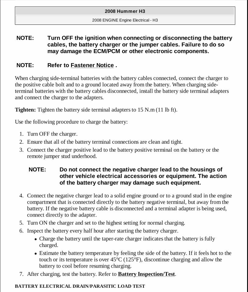
When charging side-terminal batteries with the battery cables connected, connect the charger to the positive cable bolt and to a ground located away from the battery. When charging side-terminal batteries with the battery cables disconnected, install the battery side terminal adapters and connect the charger to the adapters.
Tighten: Tighten the battery side terminal adapters to 15 N.m (11 lb ft).
Use the following procedure to charge the battery:
1. Turn OFF the charger. 2. Ensure that all of the battery terminal connections are clean and tight. 3. Connect the charger positive lead to the battery positive terminal on the battery or the
remote jumper stud underhood.
4. Connect the negative charger lead to a solid engine ground or to a ground stud in the engine compartment that is connected directly to the battery negative terminal, but away from the battery. If the negative battery cable is disconnected and a terminal adapter is being used, connect directly to the adapter.
5. Turn ON the charger and set to the highest setting for normal charging. 6. Inspect the battery every half hour after starting the battery charger.
� Charge the battery until the taper-rate charger indicates that the battery is fully charged.
� Estimate the battery temperature by feeling the side of the battery. If it feels hot to the touch or its temperature is over 45°C (125°F), discontinue charging and allow the battery to cool before resuming charging.
7. After charging, test the battery. Refer to Battery Inspection/Test.
BATTERY ELECTRICAL DRAIN/PARASITIC LOAD TEST
NOTE: Turn OFF the ignition when connecting or disconnect ing the battery cables, the battery charger or the jumper cables. F ailure to do so may damage the ECM/PCM or other electronic componen ts.
NOTE: Refer to Fastener Notice .
NOTE: Do not connect the negative charger lead to th e housings of other vehicle electrical accessories or equipment. The action of the battery charger may damage such equipment.
2008 Hummer H3
2008 ENGINE Engine Electrical - H3
MY
Sunday, March 29, 2009 10:52:05 PM Page 45 © 2005 Mitchell Repair Information Company, LLC.
Special Tools
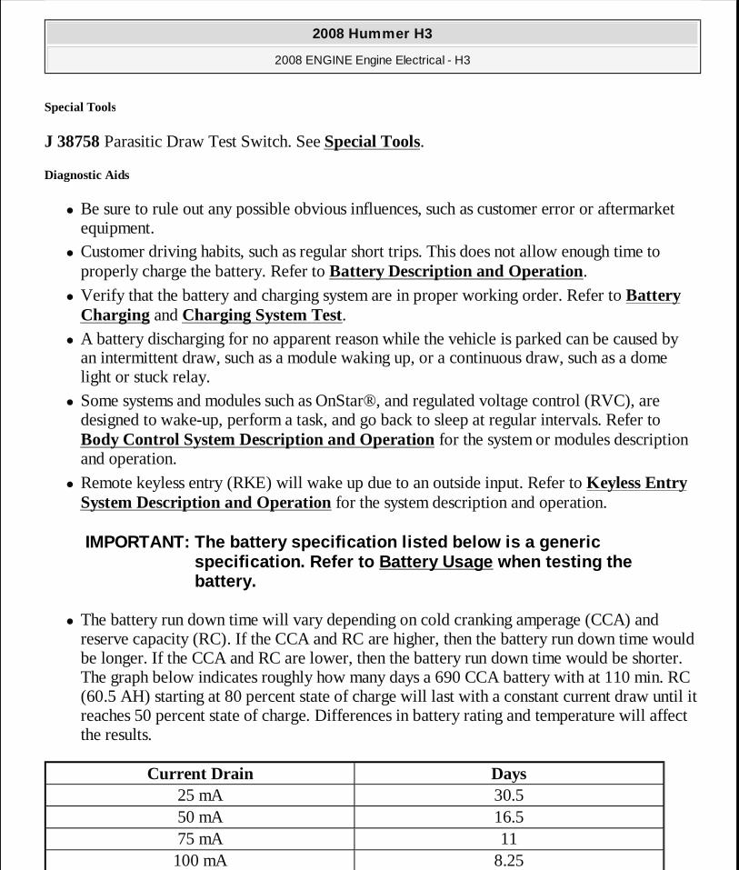
J 38758 Parasitic Draw Test Switch. See Special Tools.
Diagnostic Aids
� Be sure to rule out any possible obvious influences, such as customer error or aftermarket equipment.
� Customer driving habits, such as regular short trips. This does not allow enough time to properly charge the battery. Refer to Battery Description and Operation.
� Verify that the battery and charging system are in proper working order. Refer to Battery Charging and Charging System Test.
� A battery discharging for no apparent reason while the vehicle is parked can be caused by an intermittent draw, such as a module waking up, or a continuous draw, such as a dome light or stuck relay.
� Some systems and modules such as OnStar®, and regulated voltage control (RVC), are designed to wake-up, perform a task, and go back to sleep at regular intervals. Refer to Body Control System Description and Operation for the system or modules description and operation.
� Remote keyless entry (RKE) will wake up due to an outside input. Refer to Keyless Entry System Description and Operation for the system description and operation.
� The battery run down time will vary depending on cold cranking amperage (CCA) and reserve capacity (RC). If the CCA and RC are higher, then the battery run down time would be longer. If the CCA and RC are lower, then the battery run down time would be shorter. The graph below indicates roughly how many days a 690 CCA battery with at 110 min. RC (60.5 AH) starting at 80 percent state of charge will last with a constant current draw until it reaches 50 percent state of charge. Differences in battery rating and temperature will affect the results.
IMPORTANT: The battery specification listed below is a generic specification. Refer to Battery Usage when testing the battery.
Current Drain Days25 mA 30.550 mA 16.575 mA 11100 mA 8.25
2008 Hummer H3
2008 ENGINE Engine Electrical - H3
MY
Sunday, March 29, 2009 10:52:05 PM Page 46 © 2005 Mitchell Repair Information Company, LLC.
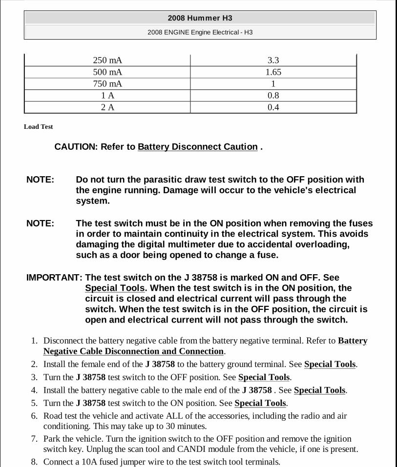
Load Test
1. Disconnect the battery negative cable from the battery negative terminal. Refer to Battery Negative Cable Disconnection and Connection.
2. Install the female end of the J 38758 to the battery ground terminal. See Special Tools. 3. Turn the J 38758 test switch to the OFF position. See Special Tools. 4. Install the battery negative cable to the male end of the J 38758 . See Special Tools. 5. Turn the J 38758 test switch to the ON position. See Special Tools. 6. Road test the vehicle and activate ALL of the accessories, including the radio and air
conditioning. This may take up to 30 minutes. 7. Park the vehicle. Turn the ignition switch to the OFF position and remove the ignition
switch key. Unplug the scan tool and CANDI module from the vehicle, if one is present. 8. Connect a 10A fused jumper wire to the test switch tool terminals.
250 mA 3.3500 mA 1.65750 mA 1
1 A 0.82 A 0.4
CAUTION: Refer to Battery Disconnect Caution .
NOTE: Do not turn the parasitic draw test switch to the OFF position with the engine running. Damage will occur to the vehicl e's electrical system.
NOTE: The test switch must be in the ON position when rem oving the fuses in order to maintain continuity in the electrical s ystem. This avoids damaging the digital multimeter due to accidental o verloading, such as a door being opened to change a fuse.
IMPORTANT: The test switch on the J 38758 is marked ON and OFF. See Special Tools . When the test switch is in the ON position, the circuit is closed and electrical current will pass through the switch. When the test switch is in the OFF position , the circuit is open and electrical current will not pass through t he switch.
2008 Hummer H3
2008 ENGINE Engine Electrical - H3
MY
Sunday, March 29, 2009 10:52:05 PM Page 47 © 2005 Mitchell Repair Information Company, LLC.
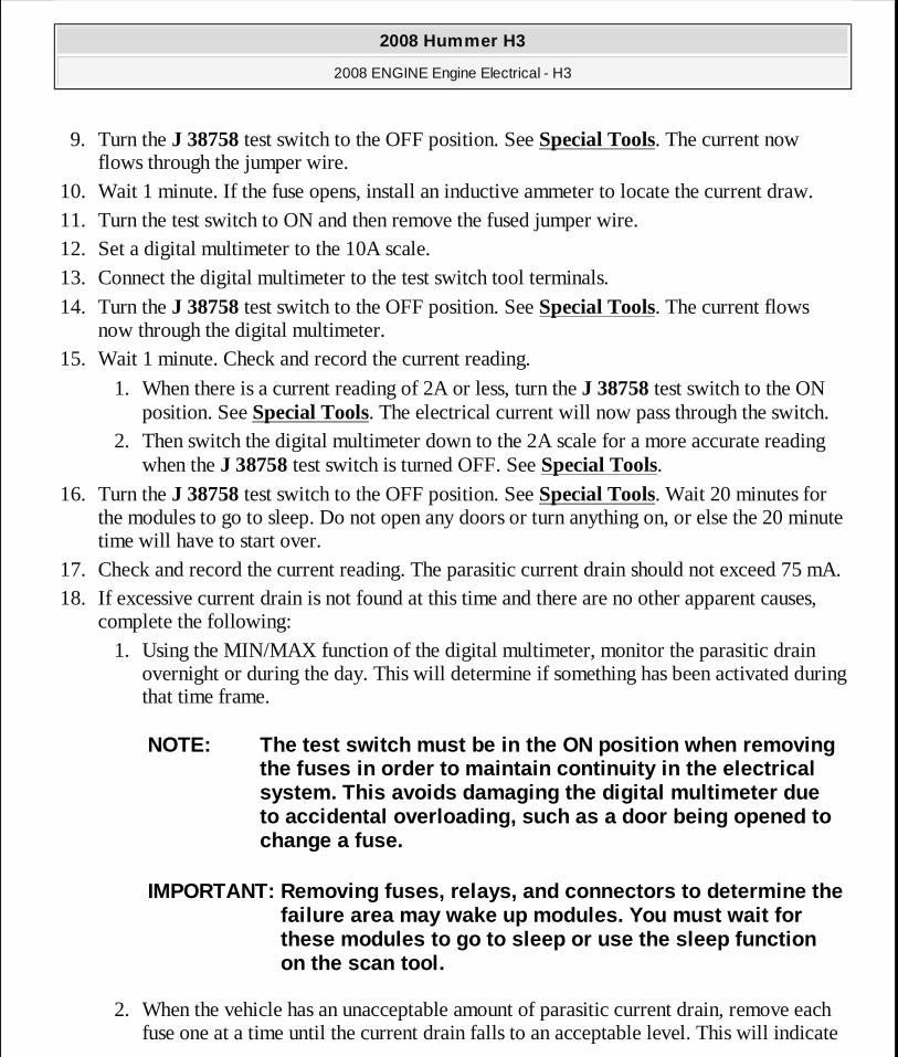
9. Turn the J 38758 test switch to the OFF position. See Special Tools. The current now flows through the jumper wire.
10. Wait 1 minute. If the fuse opens, install an inductive ammeter to locate the current draw. 11. Turn the test switch to ON and then remove the fused jumper wire. 12. Set a digital multimeter to the 10A scale. 13. Connect the digital multimeter to the test switch tool terminals.
14. Turn the J 38758 test switch to the OFF position. See Special Tools. The current flows now through the digital multimeter.
15. Wait 1 minute. Check and record the current reading.
1. When there is a current reading of 2A or less, turn the J 38758 test switch to the ON position. See Special Tools. The electrical current will now pass through the switch.
2. Then switch the digital multimeter down to the 2A scale for a more accurate reading when the J 38758 test switch is turned OFF. See Special Tools.
16. Turn the J 38758 test switch to the OFF position. See Special Tools. Wait 20 minutes for the modules to go to sleep. Do not open any doors or turn anything on, or else the 20 minute time will have to start over.
17. Check and record the current reading. The parasitic current drain should not exceed 75 mA. 18. If excessive current drain is not found at this time and there are no other apparent causes,
complete the following: 1. Using the MIN/MAX function of the digital multimeter, monitor the parasitic drain
overnight or during the day. This will determine if something has been activated during that time frame.
2. When the vehicle has an unacceptable amount of parasitic current drain, remove each fuse one at a time until the current drain falls to an acceptable level. This will indicate
NOTE: The test switch must be in the ON position whe n removing the fuses in order to maintain continuity in the el ectrical system. This avoids damaging the digital multimeter due to accidental overloading, such as a door being ope ned to change a fuse.
IMPORTANT: Removing fuses, relays, and connectors to determine the failure area may wake up modules. You must wait for these modules to go to sleep or use the sleep funct ion on the scan tool.
2008 Hummer H3
2008 ENGINE Engine Electrical - H3
MY
Sunday, March 29, 2009 10:52:05 PM Page 48 © 2005 Mitchell Repair Information Company, LLC.
which circuit is causing the drain. Refer to Power Distribution Schematics to diagnose exactly which part of the suspect circuit is causing the parasitic drain. In some cases a non-fused circuit or component, such as a relay, is the cause of excessive parasitic current drain.
3. Repeat the parasitic current drain test procedure after any repair has been completed to make sure that the parasitic current drain is at an acceptable level.
4. When the cause of the excessive current drain has been located and repaired, remove the J 38758 . See Special Tools.
19. Connect the battery negative cable to the battery negative terminal.
BATTERY COMMON CAUSES OF MALFUNCTION
A battery is not designed to last forever. With proper care, however, the battery will provide years of good service. If the battery tests good but still fails to perform well, the following are some of the more common causes:
� A vehicle accessory was left on overnight. � The driving speeds have been slow with frequent stops, stop-and-go driving, with many
electrical accessories in use, particularly air conditioning, headlights, wipers, heated rear window, cellular telephone, etc.
� The electrical load has exceeded the generator output, particularly with the addition of aftermarket equipment.
� Existing conditions in the charging system, including the following possibilities: � A slipping belt � A bad generator
� The battery has not been properly maintained, including a loose battery hold down or missing battery insulator if used.
� There are mechanical conditions in the electrical system, such as a short or a pinched wire, attributing to power failure. Refer to General Electrical Diagnosis .
Electrolyte Freezing
The freezing point of electrolyte depends on its specific gravity. A fully charged battery will not freeze until the ambient temperature gets below -54°C (-65°F). However, a battery with a low state of charge may freeze at temperatures as high as -7°C (20°F). Since freezing may ruin a battery, the battery should be protected against freezing by keeping it properly charged above 80 percent state of charge, the freezing point of the battery will be somewhere below -32°C (-25°F).
Battery Protection During Vehicle Storage
2008 Hummer H3
2008 ENGINE Engine Electrical - H3
MY
Sunday, March 29, 2009 10:52:05 PM Page 49 © 2005 Mitchell Repair Information Company, LLC.
Certain devices on the vehicle maintain a small continuous current drain, parasitic load, on the battery. A battery that is not used for an extended period of time will discharge. Eventually permanent damage will result. Discharged batteries will also freeze in cold weather. Refer to Battery Inspection/Test.
In order to maintain the battery state of charge while storing the vehicle for more than 30 days:
Disconnect the battery ground cable to protect the battery from discharge by parasitic current drains.
When the battery cannot be disconnected:
1. Maintain a high state of charge. 2. Establish a regular schedule for recharging the battery every 20-45 days.
A battery that has remained in a discharged state for a long period of time is difficult to recharge or may be permanently damaged.
CHARGING SYSTEM TEST
Diagnostic Instructions
� Perform the Diagnostic System Check - Vehicle prior to using this diagnostic procedure.
� Review Strategy Based Diagnosis for an overview of the diagnostic approach.
� Diagnostic Procedure Instructions provides an overview of each diagnostic category.
Reference Information
Description and Operation
Charging System Description and Operation
Electrical Information Reference
Testing for Intermittent Conditions and Poor Connections
Circuit/System Verification
CAUTION: Refer to BATTERY DISCONNECT CAUTION .
2008 Hummer H3
2008 ENGINE Engine Electrical - H3
MY
Sunday, March 29, 2009 10:52:05 PM Page 50 © 2005 Mitchell Repair Information Company, LLC.
Engine ON, observe the charge indicator on the instrument panel cluster (IPC) or message in the driver information center (DIC). The charge indicator on the IPC should be turned OFF and the DIC should not display charging system message.
� If the charge indicator is not on the IPC or a charging system message is not displayed on the DIC, refer to Testing for Intermittent Conditions and Poor Connections .
� If the charge indicator is on the IPC or a charging system message is displayed on the DIC, refer to Circuit/System Testing.
Circuit/System Testing
1. Ignition ON, verify that no generator or battery current sensor DTCs are set that would cause a charging system concern.
� If DTCs are set, refer to Diagnostic Trouble Code (DTC) List - Vehicle . 2. Ignition OFF, measure the voltage across the battery terminals. The voltage should read
12.0 volts or greater at room temperature.
� If not within specified value, refer to Battery Inspection/Test. 3. Connect a carbon pile tester to the battery. 4. Start the engine and increase the engine speed to 2,500 RPM. Observe the voltage reading
on the tester. The voltage should read between 12.6-15.0 volts. � If not within specified range, replace the generator.
5. Adjust the carbon pile tester to the specified load test output value, refer to Generator Usage.
� If not within specified value, replace the generator.
Repair Procedures
Perform the Diagnostic Repair Verification after completing the diagnostic procedure.
Generator Replacement (LH8) or Generator Replacement (LLR)
GENERATOR NOISE DIAGNOSIS
Diagnostic Instructions
� Perform the Diagnostic System Check - Vehicle prior to using this diagnostic procedure.
� Review Strategy Based Diagnosis for an overview of the diagnostic approach.
� Diagnostic Procedure Instructions provides an overview of each diagnostic category.
2008 Hummer H3
2008 ENGINE Engine Electrical - H3
MY
Sunday, March 29, 2009 10:52:05 PM Page 51 © 2005 Mitchell Repair Information Company, LLC.
Diagnostic Aids
Noise from a generator may be due to electrical or mechanical noise. Electrical noise or magnetic whine usually varies with the electrical load placed on the generator and is a normal operating characteristic of all generators. When diagnosing a noisy generator, it is important to remember that loose or misaligned components around the generator may transmit the noise into the passenger compartment and that replacing the generator may not solve the problem.
Circuit/System Testing
1. Start the engine, verify the noise can be heard. Compare the concern to a similar vehicle. 2. Inspect the generator, generator mounting, wiring harness, heater hoses, A/C lines or other
accessory equipment that may be misrouted or be the cause of noise being transmitted into the passenger compartment.
3. Ignition OFF, remove the engine drive belt. Verify the generator, idler pulley and tensioner pulley spin freely.
� If any of the pulleys do not spin freely, replace the affected component. 4. Loosen all generator mounting bolts and ensure the generator is properly aligned. Tighten
mounting bolts to specification, refer to Generator Replacement (LH8) or Generator Replacement (LLR).
Repair Procedures
Perform the Diagnostic Repair Verification after completing the diagnostic procedure.
� Drive Belt Replacement (Without A/C) or Drive Belt Replacement (With A/C) for the 3.7L engine (LLS) or Drive Belt Replacement - Accessory for the 5.3L engine (LH8)
� Drive Belt Tensioner Replacement for the 3.7L engine (LLS) or Drive Belt Tensioner Replacement - Accessory for the 5.3L engine (LH8)
� Drive Belt Idler Pulley Replacement for the 3.7L engine (LLS) or Drive Belt Idler Pulley Replacement for the 5.3L (LH8) engine
� Generator Replacement (LH8) or Generator Replacement (LLR)
STARTER SOLENOID DOES NOT CLICK (AUTOMATIC M30)
Diagnostic Instructions
� Perform the Diagnostic System Check - Vehicle prior to using this diagnostic procedure.
� Review Strategy Based Diagnosis for an overview of the diagnostic approach.
� Diagnostic Procedure Instructions provides an overview of each diagnostic category.
2008 Hummer H3
2008 ENGINE Engine Electrical - H3
MY
Sunday, March 29, 2009 10:52:05 PM Page 52 © 2005 Mitchell Repair Information Company, LLC.
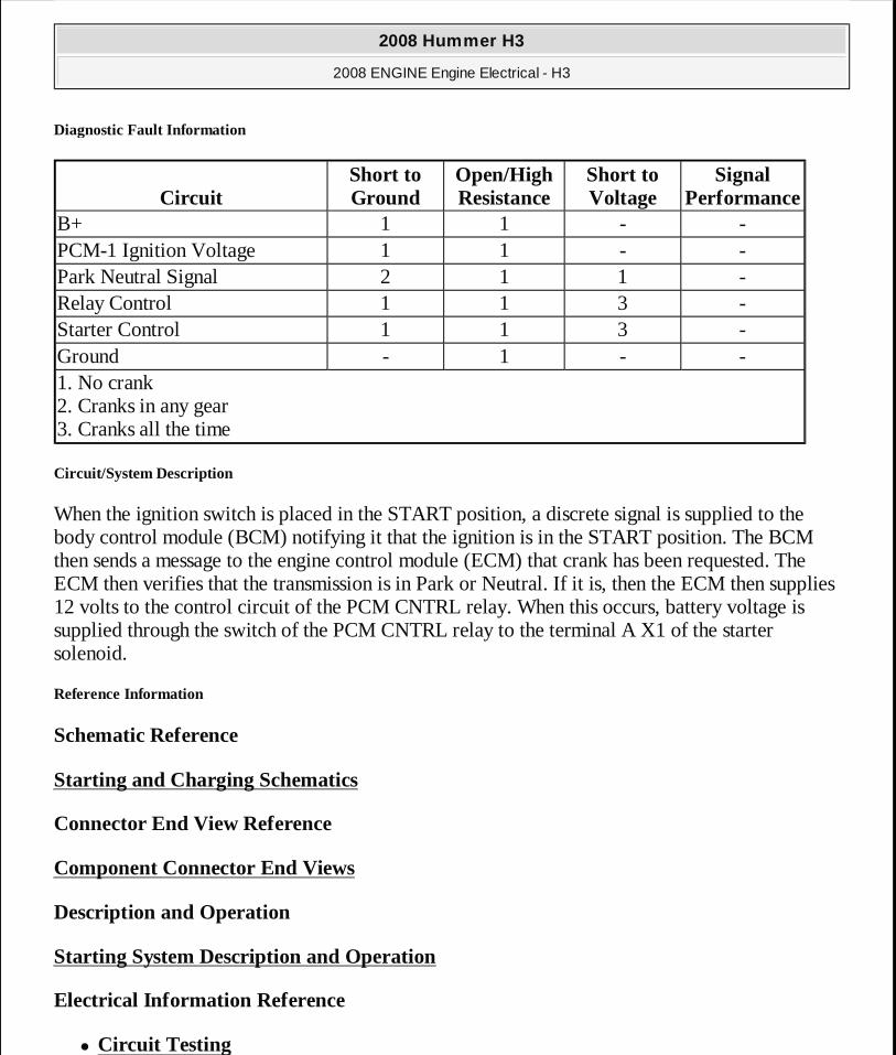
Diagnostic Fault Information
Circuit/System Description
When the ignition switch is placed in the START position, a discrete signal is supplied to the body control module (BCM) notifying it that the ignition is in the START position. The BCM then sends a message to the engine control module (ECM) that crank has been requested. The ECM then verifies that the transmission is in Park or Neutral. If it is, then the ECM then supplies 12 volts to the control circuit of the PCM CNTRL relay. When this occurs, battery voltage is supplied through the switch of the PCM CNTRL relay to the terminal A X1 of the starter solenoid.
Reference Information
Schematic Reference
Starting and Charging Schematics
Connector End View Reference
Component Connector End Views
Description and Operation
Starting System Description and Operation
Electrical Information Reference
� Circuit Testing
CircuitShort to Ground
Open/High Resistance
Short to Voltage
Signal Performance
B+ 1 1 - -PCM-1 Ignition Voltage 1 1 - -Park Neutral Signal 2 1 1 -Relay Control 1 1 3 -Starter Control 1 1 3 -Ground - 1 - -1. No crank 2. Cranks in any gear 3. Cranks all the time
2008 Hummer H3
2008 ENGINE Engine Electrical - H3
MY
Sunday, March 29, 2009 10:52:06 PM Page 53 © 2005 Mitchell Repair Information Company, LLC.
� Connector Repairs � Testing for Intermittent Conditions and Poor Connections
� Wiring Repairs
DTC Type Reference
Powertrain Diagnostic Trouble Code (DTC) Type Definitions
Scan Tool Reference
Control Module References for scan tool information
Circuit/System Verification
1. Ignition ON, verify that the scan tool ECM Ignition 1 Signal parameter displays B+. � If less than the specified value, test the PCM-1 fuse, the RUN/CRNK relay, and the
ignition voltage circuit for an open/high resistance. If the circuit tests normal, replace the ECM.
2. Verify that no starter relay, theft deterrent, or automatic transmission DTCs are set that would cause the ECM to disable starting.
� If DTCs are set, refer to Diagnostic Trouble Code (DTC) List - Vehicle . 3. Observe the scan tool ECM Crank Request Signal parameter. Place ignition switch in the
crank position. Verify that the scan tool displays Yes.
� If not the specified value, refer to Power Mode Mismatch . 4. Transmission range selector in park. Verify that the scan tool ECM PNP Switch parameter
displays Park/Neutral. � If the ECM PNP Switch parameter does not indicate Park/Neutral, refer to
Circuit/System Testing. 5. Transmission range selector in park or neutral. Attempt to start the vehicle. The PCM
CNTRL relay should click and the engine should begin cranking.
� If the PCM CNTRL relay does not click or the engine does not crank, refer to PCM CNTRL .
6. If all circuits test normal, replace the ECM.
Circuit/System Testing
PNP Switch Circuit Malfunction
2008 Hummer H3
2008 ENGINE Engine Electrical - H3
MY
Sunday, March 29, 2009 10:52:06 PM Page 54 © 2005 Mitchell Repair Information Company, LLC.
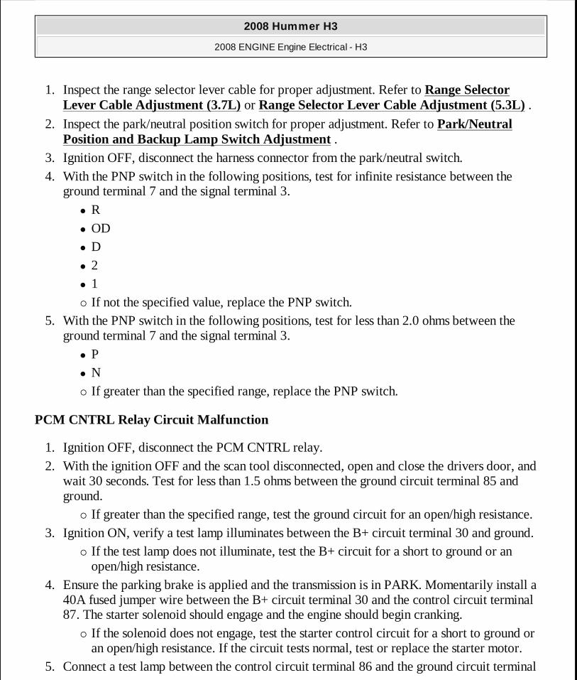
1. Inspect the range selector lever cable for proper adjustment. Refer to Range Selector Lever Cable Adjustment (3.7L) or Range Selector Lever Cable Adjustment (5.3L) .
2. Inspect the park/neutral position switch for proper adjustment. Refer to Park/Neutral Position and Backup Lamp Switch Adjustment .
3. Ignition OFF, disconnect the harness connector from the park/neutral switch. 4. With the PNP switch in the following positions, test for infinite resistance between the
ground terminal 7 and the signal terminal 3. � R � OD � D � 2 � 1 � If not the specified value, replace the PNP switch.
5. With the PNP switch in the following positions, test for less than 2.0 ohms between the ground terminal 7 and the signal terminal 3.
� P � N � If greater than the specified range, replace the PNP switch.
PCM CNTRL Relay Circuit Malfunction
1. Ignition OFF, disconnect the PCM CNTRL relay. 2. With the ignition OFF and the scan tool disconnected, open and close the drivers door, and
wait 30 seconds. Test for less than 1.5 ohms between the ground circuit terminal 85 and ground.
� If greater than the specified range, test the ground circuit for an open/high resistance. 3. Ignition ON, verify a test lamp illuminates between the B+ circuit terminal 30 and ground.
� If the test lamp does not illuminate, test the B+ circuit for a short to ground or an open/high resistance.
4. Ensure the parking brake is applied and the transmission is in PARK. Momentarily install a 40A fused jumper wire between the B+ circuit terminal 30 and the control circuit terminal 87. The starter solenoid should engage and the engine should begin cranking.
� If the solenoid does not engage, test the starter control circuit for a short to ground or an open/high resistance. If the circuit tests normal, test or replace the starter motor.
5. Connect a test lamp between the control circuit terminal 86 and the ground circuit terminal
2008 Hummer H3
2008 ENGINE Engine Electrical - H3
MY
Sunday, March 29, 2009 10:52:06 PM Page 55 © 2005 Mitchell Repair Information Company, LLC.
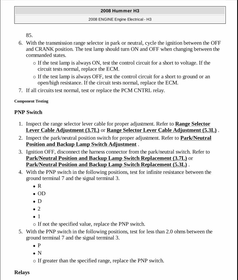
85. 6. With the transmission range selector in park or neutral, cycle the ignition between the OFF
and CRANK position. The test lamp should turn ON and OFF when changing between the commanded states.
� If the test lamp is always ON, test the control circuit for a short to voltage. If the circuit tests normal, replace the ECM.
� If the test lamp is always OFF, test the control circuit for a short to ground or an open/high resistance. If the circuit tests normal, replace the ECM.
7. If all circuits test normal, test or replace the PCM CNTRL relay.
Component Testing
PNP Switch
1. Inspect the range selector lever cable for proper adjustment. Refer to Range Selector Lever Cable Adjustment (3.7L) or Range Selector Lever Cable Adjustment (5.3L) .
2. Inspect the park/neutral position switch for proper adjustment. Refer to Park/Neutral Position and Backup Lamp Switch Adjustment .
3. Ignition OFF, disconnect the harness connector from the park/neutral switch. Refer to Park/Neutral Position and Backup Lamp Switch Replacement (3.7L) or Park/Neutral Position and Backup Lamp Switch Replacement (5.3L) .
4. With the PNP switch in the following positions, test for infinite resistance between the ground terminal 7 and the signal terminal 3.
� R � OD � D � 2 � 1 � If not the specified value, replace the PNP switch.
5. With the PNP switch in the following positions, test for less than 2.0 ohms between the ground terminal 7 and the signal terminal 3.
� P � N � If greater than the specified range, replace the PNP switch.
Relays
2008 Hummer H3
2008 ENGINE Engine Electrical - H3
MY
Sunday, March 29, 2009 10:52:06 PM Page 56 © 2005 Mitchell Repair Information Company, LLC.
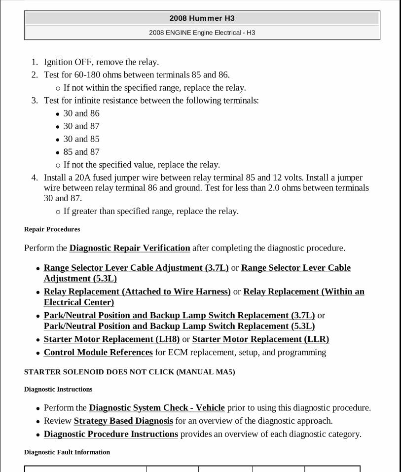
1. Ignition OFF, remove the relay. 2. Test for 60-180 ohms between terminals 85 and 86.
� If not within the specified range, replace the relay. 3. Test for infinite resistance between the following terminals:
� 30 and 86 � 30 and 87 � 30 and 85 � 85 and 87 � If not the specified value, replace the relay.
4. Install a 20A fused jumper wire between relay terminal 85 and 12 volts. Install a jumper wire between relay terminal 86 and ground. Test for less than 2.0 ohms between terminals 30 and 87.
� If greater than specified range, replace the relay.
Repair Procedures
Perform the Diagnostic Repair Verification after completing the diagnostic procedure.
� Range Selector Lever Cable Adjustment (3.7L) or Range Selector Lever Cable Adjustment (5.3L)
� Relay Replacement (Attached to Wire Harness) or Relay Replacement (Within an Electrical Center)
� Park/Neutral Position and Backup Lamp Switch Replacement (3.7L) or Park/Neutral Position and Backup Lamp Switch Replacement (5.3L)
� Starter Motor Replacement (LH8) or Starter Motor Replacement (LLR) � Control Module References for ECM replacement, setup, and programming
STARTER SOLENOID DOES NOT CLICK (MANUAL MA5)
Diagnostic Instructions
� Perform the Diagnostic System Check - Vehicle prior to using this diagnostic procedure.
� Review Strategy Based Diagnosis for an overview of the diagnostic approach.
� Diagnostic Procedure Instructions provides an overview of each diagnostic category.
Diagnostic Fault Information
2008 Hummer H3
2008 ENGINE Engine Electrical - H3
MY
Sunday, March 29, 2009 10:52:06 PM Page 57 © 2005 Mitchell Repair Information Company, LLC.
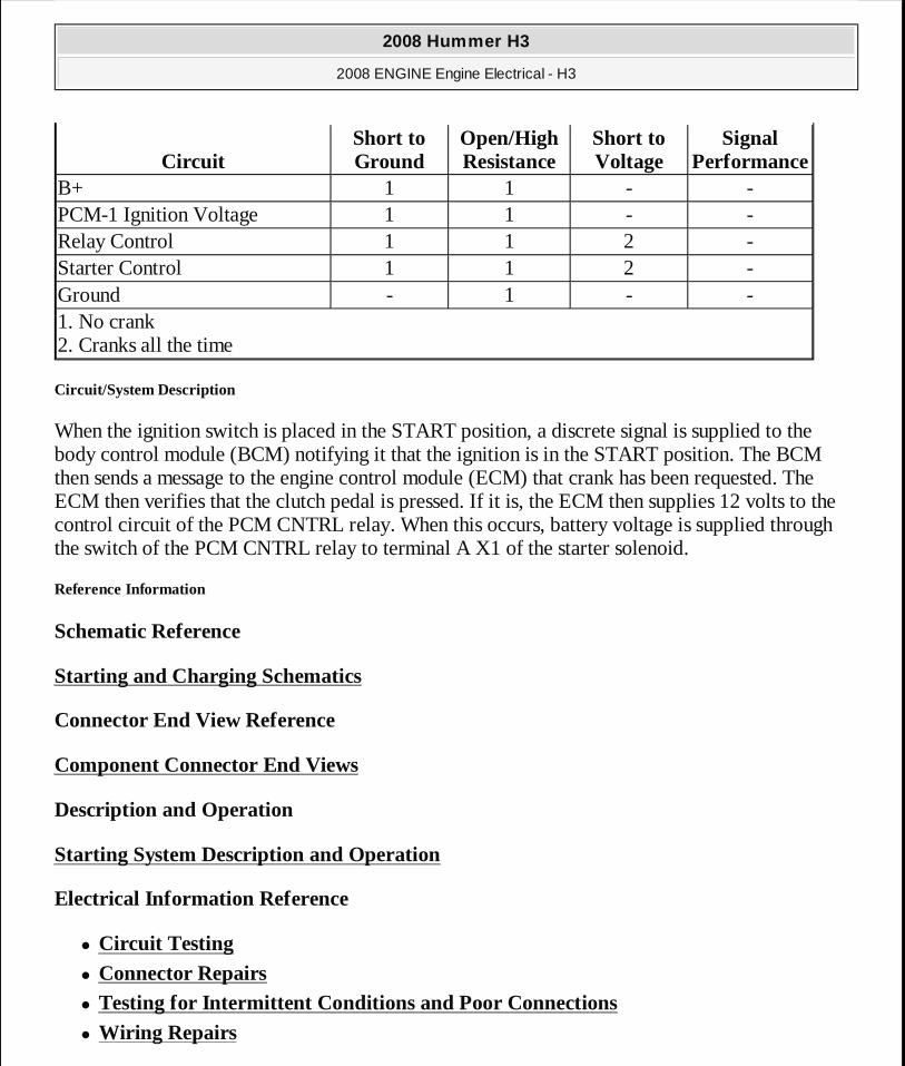
Circuit/System Description
When the ignition switch is placed in the START position, a discrete signal is supplied to the body control module (BCM) notifying it that the ignition is in the START position. The BCM then sends a message to the engine control module (ECM) that crank has been requested. The ECM then verifies that the clutch pedal is pressed. If it is, the ECM then supplies 12 volts to the control circuit of the PCM CNTRL relay. When this occurs, battery voltage is supplied through the switch of the PCM CNTRL relay to terminal A X1 of the starter solenoid.
Reference Information
Schematic Reference
Starting and Charging Schematics
Connector End View Reference
Component Connector End Views
Description and Operation
Starting System Description and Operation
Electrical Information Reference
� Circuit Testing
� Connector Repairs � Testing for Intermittent Conditions and Poor Connections
� Wiring Repairs
CircuitShort to Ground
Open/High Resistance
Short to Voltage
Signal Performance
B+ 1 1 - -PCM-1 Ignition Voltage 1 1 - -Relay Control 1 1 2 -Starter Control 1 1 2 -Ground - 1 - -1. No crank 2. Cranks all the time
2008 Hummer H3
2008 ENGINE Engine Electrical - H3
MY
Sunday, March 29, 2009 10:52:06 PM Page 58 © 2005 Mitchell Repair Information Company, LLC.
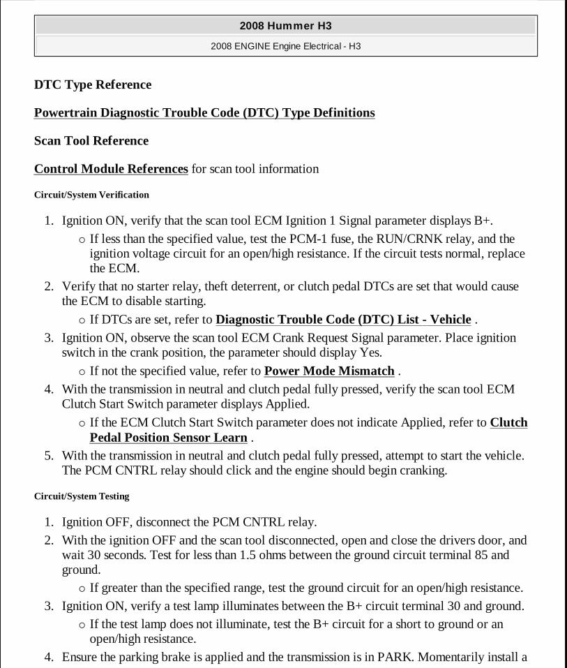
DTC Type Reference
Powertrain Diagnostic Trouble Code (DTC) Type Definitions
Scan Tool Reference
Control Module References for scan tool information
Circuit/System Verification
1. Ignition ON, verify that the scan tool ECM Ignition 1 Signal parameter displays B+. � If less than the specified value, test the PCM-1 fuse, the RUN/CRNK relay, and the
ignition voltage circuit for an open/high resistance. If the circuit tests normal, replace the ECM.
2. Verify that no starter relay, theft deterrent, or clutch pedal DTCs are set that would cause the ECM to disable starting.
� If DTCs are set, refer to Diagnostic Trouble Code (DTC) List - Vehicle . 3. Ignition ON, observe the scan tool ECM Crank Request Signal parameter. Place ignition
switch in the crank position, the parameter should display Yes.
� If not the specified value, refer to Power Mode Mismatch . 4. With the transmission in neutral and clutch pedal fully pressed, verify the scan tool ECM
Clutch Start Switch parameter displays Applied.
� If the ECM Clutch Start Switch parameter does not indicate Applied, refer to Clutch Pedal Position Sensor Learn .
5. With the transmission in neutral and clutch pedal fully pressed, attempt to start the vehicle. The PCM CNTRL relay should click and the engine should begin cranking.
Circuit/System Testing
1. Ignition OFF, disconnect the PCM CNTRL relay. 2. With the ignition OFF and the scan tool disconnected, open and close the drivers door, and
wait 30 seconds. Test for less than 1.5 ohms between the ground circuit terminal 85 and ground.
� If greater than the specified range, test the ground circuit for an open/high resistance. 3. Ignition ON, verify a test lamp illuminates between the B+ circuit terminal 30 and ground.
� If the test lamp does not illuminate, test the B+ circuit for a short to ground or an open/high resistance.
4. Ensure the parking brake is applied and the transmission is in PARK. Momentarily install a
2008 Hummer H3
2008 ENGINE Engine Electrical - H3
MY
Sunday, March 29, 2009 10:52:06 PM Page 59 © 2005 Mitchell Repair Information Company, LLC.
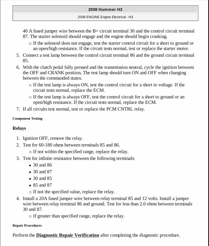
40 A fused jumper wire between the B+ circuit terminal 30 and the control circuit terminal 87. The starter solenoid should engage and the engine should begin cranking.
� If the solenoid does not engage, test the starter control circuit for a short to ground or an open/high resistance. If the circuit tests normal, test or replace the starter motor.
5. Connect a test lamp between the control circuit terminal 86 and the ground circuit terminal 85.
6. With the clutch pedal fully pressed and the transmission neutral, cycle the ignition between the OFF and CRANK position. The test lamp should turn ON and OFF when changing between the commanded states.
� If the test lamp is always ON, test the control circuit for a short to voltage. If the circuit tests normal, replace the ECM.
� If the test lamp is always OFF, test the control circuit for a short to ground or an open/high resistance. If the circuit tests normal, replace the ECM.
7. If all circuits test normal, test or replace the PCM CNTRL relay.
Component Testing
Relays
1. Ignition OFF, remove the relay. 2. Test for 60-180 ohms between terminals 85 and 86.
� If not within the specified range, replace the relay. 3. Test for infinite resistance between the following terminals:
� 30 and 86 � 30 and 87 � 30 and 85 � 85 and 87 � If not the specified value, replace the relay.
4. Install a 20A fused jumper wire between relay terminal 85 and 12 volts. Install a jumper wire between relay terminal 86 and ground. Test for less than 2.0 ohms between terminals 30 and 87.
� If greater than specified range, replace the relay.
Repair Procedures
Perform the Diagnostic Repair Verification after completing the diagnostic procedure.
2008 Hummer H3
2008 ENGINE Engine Electrical - H3
MY
Sunday, March 29, 2009 10:52:06 PM Page 60 © 2005 Mitchell Repair Information Company, LLC.
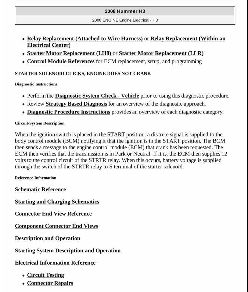
� Relay Replacement (Attached to Wire Harness) or Relay Replacement (Within an Electrical Center)
� Starter Motor Replacement (LH8) or Starter Motor Replacement (LLR) � Control Module References for ECM replacement, setup, and programming
STARTER SOLENOID CLICKS, ENGINE DOES NOT CRANK
Diagnostic Instructions
� Perform the Diagnostic System Check - Vehicle prior to using this diagnostic procedure.
� Review Strategy Based Diagnosis for an overview of the diagnostic approach.
� Diagnostic Procedure Instructions provides an overview of each diagnostic category.
Circuit/System Description
When the ignition switch is placed in the START position, a discrete signal is supplied to the body control module (BCM) notifying it that the ignition is in the START position. The BCM then sends a message to the engine control module (ECM) that crank has been requested. The ECM then verifies that the transmission is in Park or Neutral. If it is, the ECM then supplies 12 volts to the control circuit of the STRTR relay. When this occurs, battery voltage is supplied through the switch of the STRTR relay to S terminal of the starter solenoid.
Reference Information
Schematic Reference
Starting and Charging Schematics
Connector End View Reference
Component Connector End Views
Description and Operation
Starting System Description and Operation
Electrical Information Reference
� Circuit Testing
� Connector Repairs
2008 Hummer H3
2008 ENGINE Engine Electrical - H3
MY
Sunday, March 29, 2009 10:52:06 PM Page 61 © 2005 Mitchell Repair Information Company, LLC.
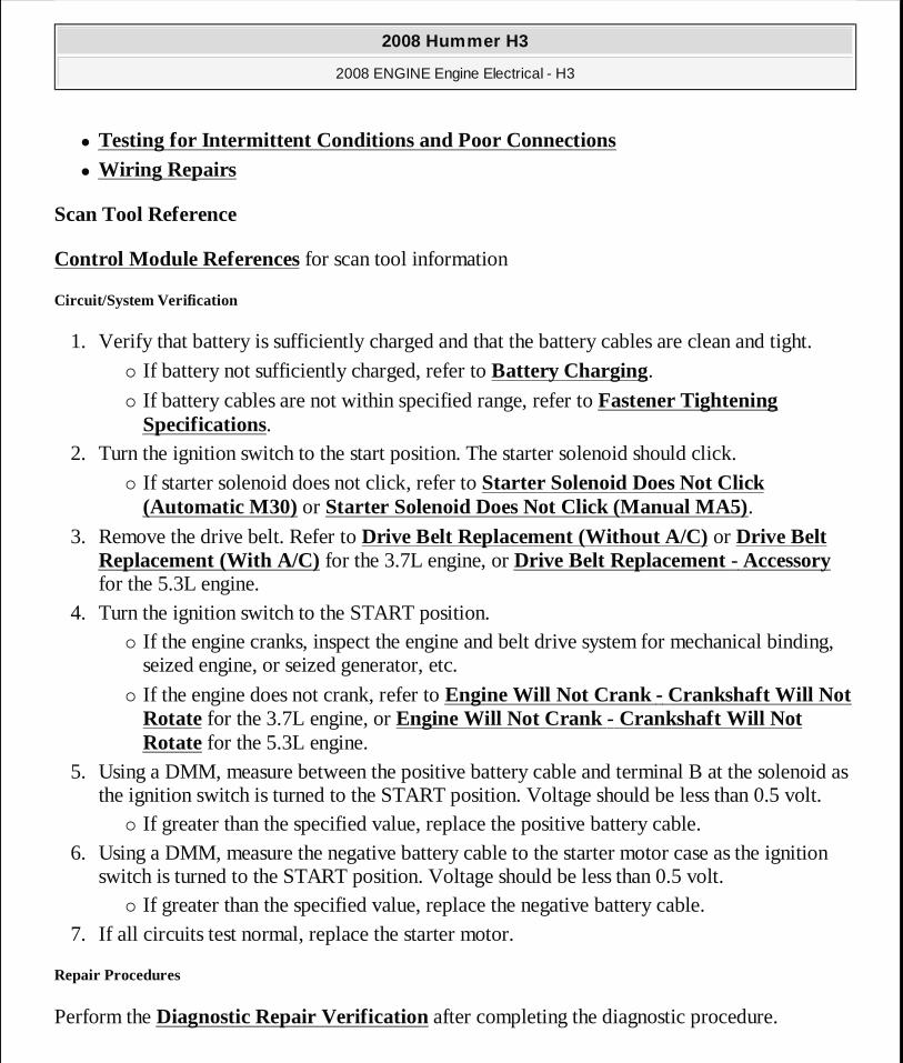
� Testing for Intermittent Conditions and Poor Connections
� Wiring Repairs
Scan Tool Reference
Control Module References for scan tool information
Circuit/System Verification
1. Verify that battery is sufficiently charged and that the battery cables are clean and tight.
� If battery not sufficiently charged, refer to Battery Charging.
� If battery cables are not within specified range, refer to Fastener Tightening Specifications.
2. Turn the ignition switch to the start position. The starter solenoid should click.
� If starter solenoid does not click, refer to Starter Solenoid Does Not Click (Automatic M30) or Starter Solenoid Does Not Click (Manual MA5).
3. Remove the drive belt. Refer to Drive Belt Replacement (Without A/C) or Drive Belt Replacement (With A/C) for the 3.7L engine, or Drive Belt Replacement - Accessory for the 5.3L engine.
4. Turn the ignition switch to the START position. � If the engine cranks, inspect the engine and belt drive system for mechanical binding,
seized engine, or seized generator, etc.
� If the engine does not crank, refer to Engine Will Not Crank - Crankshaft Will Not Rotate for the 3.7L engine, or Engine Will Not Crank - Crankshaft Will Not Rotate for the 5.3L engine.
5. Using a DMM, measure between the positive battery cable and terminal B at the solenoid as the ignition switch is turned to the START position. Voltage should be less than 0.5 volt.
� If greater than the specified value, replace the positive battery cable. 6. Using a DMM, measure the negative battery cable to the starter motor case as the ignition
switch is turned to the START position. Voltage should be less than 0.5 volt. � If greater than the specified value, replace the negative battery cable.
7. If all circuits test normal, replace the starter motor.
Repair Procedures
Perform the Diagnostic Repair Verification after completing the diagnostic procedure.
2008 Hummer H3
2008 ENGINE Engine Electrical - H3
MY
Sunday, March 29, 2009 10:52:06 PM Page 62 © 2005 Mitchell Repair Information Company, LLC.
� Battery Positive and Negative Cable Replacement (LLR) � Starter Motor Replacement (LH8) or Starter Motor Replacement (LLR)
ENGINE CRANKS SLOWLY
Inspect the following items:
� Battery-Perform the Battery Inspection/Test. Refer to Battery Inspection/Test. � Wiring-Inspect the wiring for damage. Inspect all connections to the starter motor, the
solenoid, the battery, and all ground connections. Refer to:
� Circuit Testing
� Wiring Repairs
� Testing for Intermittent Conditions and Poor Connections
� Connector Repairs � Engine-Verify that the engine is not seized.
If the battery, the wiring, and the engine are functioning properly, and the engine continues to crank slowly, replace the starter motor. Refer to Starter Motor Replacement (LH8) or Starter Motor Replacement (LLR).
STARTER MOTOR NOISE DIAGNOSIS
Diagnostic Instructions
� Perform the Diagnostic System Check - Vehicle prior to using this diagnostic procedure.
� Review Strategy Based Diagnosis for an overview of the diagnostic approach.
� Diagnostic Procedure Instructions provides an overview of each diagnostic category.
Circuit/System Testing
1. Remove the flywheel inspection cover. 2. Inspect the flywheel for the following:
� Loose flywheel bolts � Chipped gear teeth � Missing gear teeth � Bent flywheel
� If not within specifications, secure the flywheel bolts or replace the flywheel.
2008 Hummer H3
2008 ENGINE Engine Electrical - H3
MY
Sunday, March 29, 2009 10:52:06 PM Page 63 © 2005 Mitchell Repair Information Company, LLC.
� If all inspections were within specification, replace the starter motor.
Repair Procedures
� Fastener Tightening Specifications for the 3.7L engine or Fastener Tightening Specifications for the 5.3L engine
� Engine Flywheel Replacement (with Automatic Transmission) or Engine Flywheel Replacement (with Manual Transmission) for the 3.7L engine or Automatic Transmission Flex Plate Replacement for the 5.3L engine
� Starter Motor Replacement (LH8) or Starter Motor Replacement (LLR)
REPAIR INSTRUCTIONS
BATTERY NEGATIVE CABLE DISCONNECTION AND CONNECTION
Disconnecting Procedure
CAUTION: Batteries produce explosive gases. Batterie s contain corrosive acid. Batteries supply levels of electric al current high enough to cause burns. Therefore, in order to reduce the risk of personal injury while working near a batter y, observe the following guidelines:
� Always shield your eyes. � Avoid leaning over the battery whenever possible. � Do not expose the battery to open flames or sparks. � Do not allow battery acid to contact the eyes or th e skin.
� Flush any contacted areas with water immediately and thoroughly.
� Get medical help.
CAUTION: Unless directed otherwise, the ignition and start switch must be in the OFF or LOCK position, and all electrical loads must be OFF before servicing any electrical component. D isconnect the negative battery cable to prevent an electrical spark should a tool or equipment come in contact with an exposed electrical terminal. Failure to follow these precau tions may result in personal injury and/or damage to the vehi cle or its
2008 Hummer H3
2008 ENGINE Engine Electrical - H3
MY
Sunday, March 29, 2009 10:52:06 PM Page 64 © 2005 Mitchell Repair Information Company, LLC.
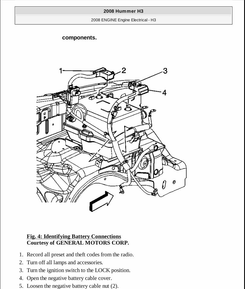
Fig. 4: Identifying Battery Connections Courtesy of GENERAL MOTORS CORP.
1. Record all preset and theft codes from the radio. 2. Turn off all lamps and accessories. 3. Turn the ignition switch to the LOCK position. 4. Open the negative battery cable cover. 5. Loosen the negative battery cable nut (2).
components.
2008 Hummer H3
2008 ENGINE Engine Electrical - H3
MY
Sunday, March 29, 2009 10:52:06 PM Page 65 © 2005 Mitchell Repair Information Company, LLC.
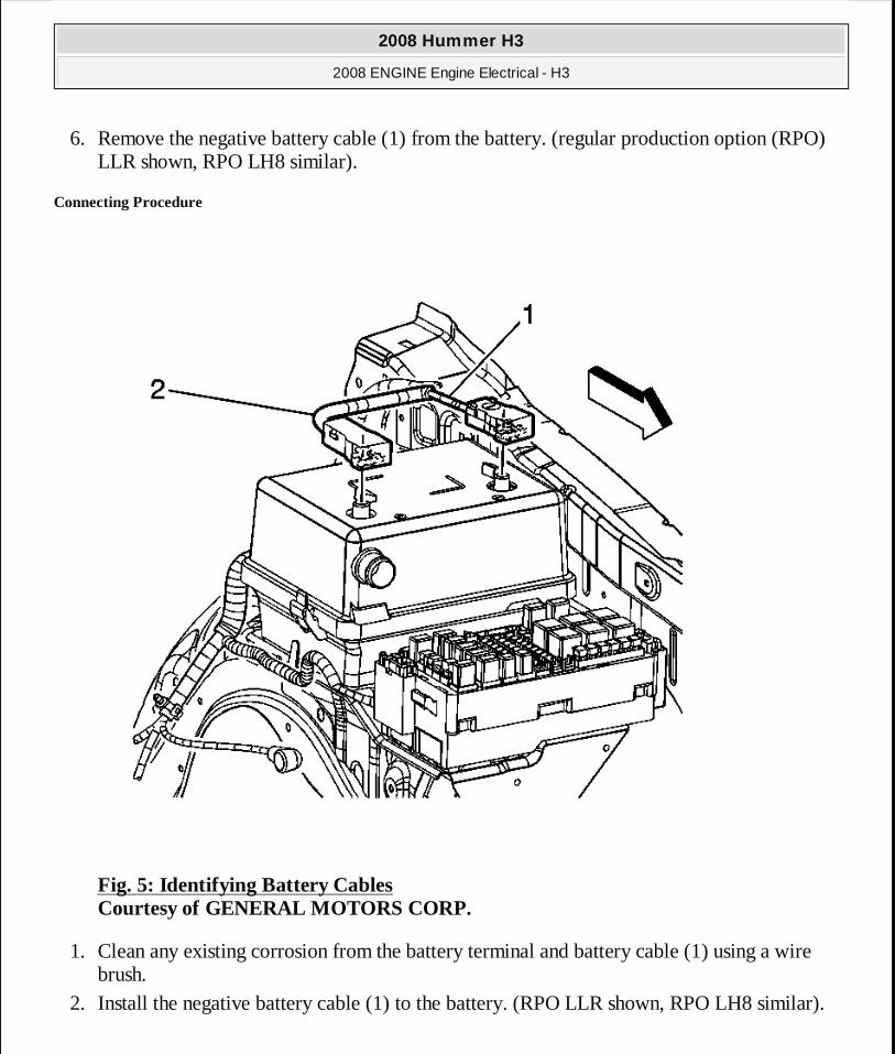
6. Remove the negative battery cable (1) from the battery. (regular production option (RPO) LLR shown, RPO LH8 similar).
Connecting Procedure
Fig. 5: Identifying Battery Cables Courtesy of GENERAL MOTORS CORP.
1. Clean any existing corrosion from the battery terminal and battery cable (1) using a wire brush.
2. Install the negative battery cable (1) to the battery. (RPO LLR shown, RPO LH8 similar).
2008 Hummer H3
2008 ENGINE Engine Electrical - H3
MY
Sunday, March 29, 2009 10:52:06 PM Page 66 © 2005 Mitchell Repair Information Company, LLC.
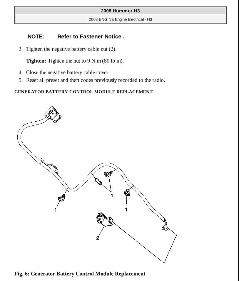
3. Tighten the negative battery cable nut (2).
Tighten: Tighten the nut to 9 N.m (80 lb in).
4. Close the negative battery cable cover. 5. Reset all preset and theft codes previously recorded to the radio.
GENERATOR BATTERY CONTROL MODULE REPLACEMENT
Fig. 6: Generator Battery Control Module Replacement
NOTE: Refer to Fastener Notice .
2008 Hummer H3
2008 ENGINE Engine Electrical - H3
MY
Sunday, March 29, 2009 10:52:06 PM Page 67 © 2005 Mitchell Repair Information Company, LLC.
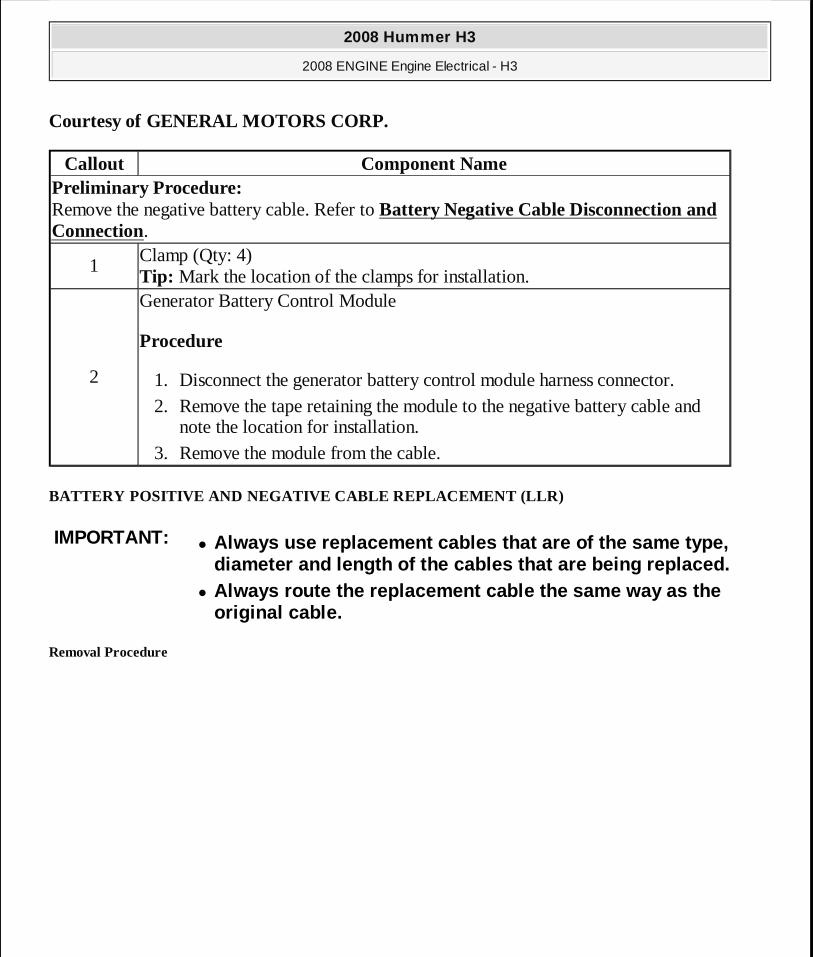
Courtesy of GENERAL MOTORS CORP.
BATTERY POSITIVE AND NEGATIVE CABLE REPLACEMENT (LL R)
Removal Procedure
Callout Component NamePreliminary Procedure: Remove the negative battery cable. Refer to Battery Negative Cable Disconnection and Connection.
1Clamp (Qty: 4) Tip: Mark the location of the clamps for installation.
2
Generator Battery Control Module
Procedure
1. Disconnect the generator battery control module harness connector. 2. Remove the tape retaining the module to the negative battery cable and
note the location for installation. 3. Remove the module from the cable.
IMPORTANT:� Always use replacement cables that are of the same type,
diameter and length of the cables that are being re placed. � Always route the replacement cable the same way as the
original cable.
2008 Hummer H3
2008 ENGINE Engine Electrical - H3
MY
Sunday, March 29, 2009 10:52:06 PM Page 68 © 2005 Mitchell Repair Information Company, LLC.
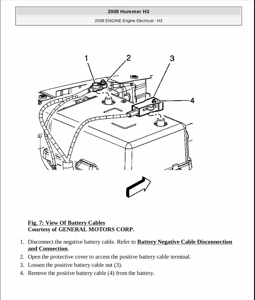
Fig. 7: View Of Battery Cables Courtesy of GENERAL MOTORS CORP.
1. Disconnect the negative battery cable. Refer to Battery Negative Cable Disconnection and Connection.
2. Open the protective cover to access the positive battery cable terminal. 3. Loosen the positive battery cable nut (3). 4. Remove the positive battery cable (4) from the battery.
2008 Hummer H3
2008 ENGINE Engine Electrical - H3
MY
Sunday, March 29, 2009 10:52:06 PM Page 69 © 2005 Mitchell Repair Information Company, LLC.

Fig. 8: Identifying Engine Wiring Harness Connector & Retaining Clips Courtesy of GENERAL MOTORS CORP.
5. Disconnect the engine wiring harness electrical connector (1) from the generator battery control module.
6. Remove the engine wiring harness clip (2) from the upper battery box.
2008 Hummer H3
2008 ENGINE Engine Electrical - H3
MY
Sunday, March 29, 2009 10:52:06 PM Page 70 © 2005 Mitchell Repair Information Company, LLC.
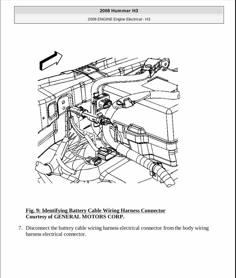
Fig. 9: Identifying Battery Cable Wiring Harness Connector Courtesy of GENERAL MOTORS CORP.
7. Disconnect the battery cable wiring harness electrical connector from the body wiring harness electrical connector.
2008 Hummer H3
2008 ENGINE Engine Electrical - H3
MY
Sunday, March 29, 2009 10:52:06 PM Page 71 © 2005 Mitchell Repair Information Company, LLC.
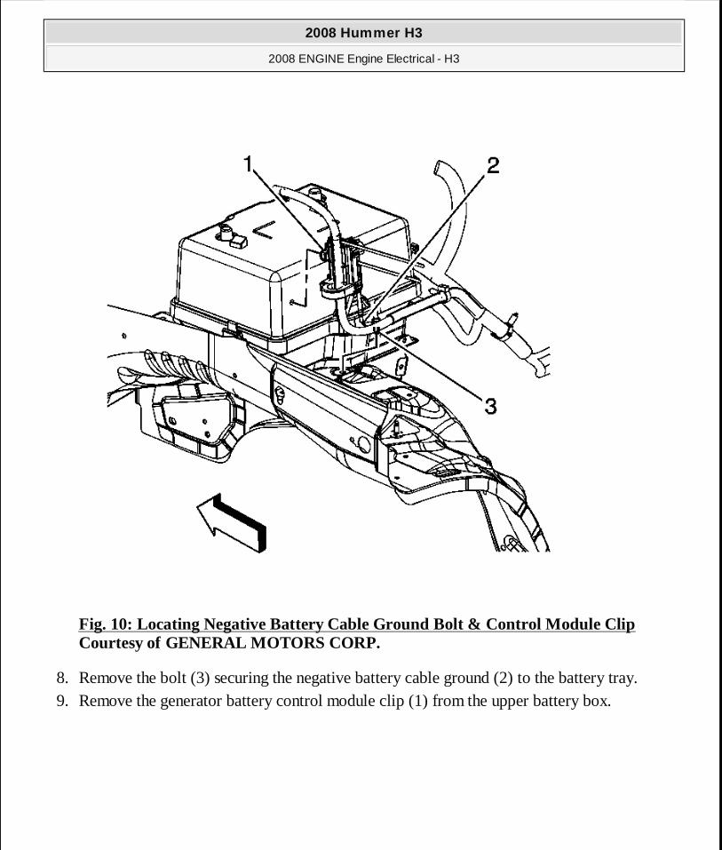
Fig. 10: Locating Negative Battery Cable Ground Bolt & Control Module Clip Courtesy of GENERAL MOTORS CORP.
8. Remove the bolt (3) securing the negative battery cable ground (2) to the battery tray. 9. Remove the generator battery control module clip (1) from the upper battery box.
2008 Hummer H3
2008 ENGINE Engine Electrical - H3
MY
Sunday, March 29, 2009 10:52:06 PM Page 72 © 2005 Mitchell Repair Information Company, LLC.
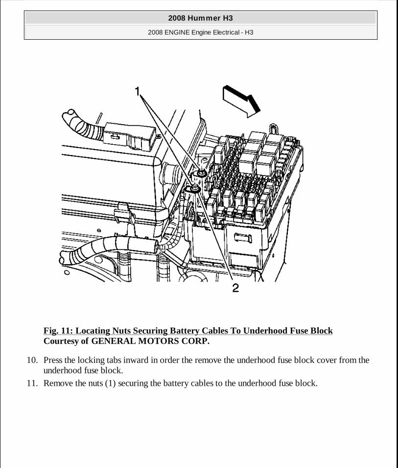
Fig. 11: Locating Nuts Securing Battery Cables To Underhood Fuse Block Courtesy of GENERAL MOTORS CORP.
10. Press the locking tabs inward in order the remove the underhood fuse block cover from the underhood fuse block.
11. Remove the nuts (1) securing the battery cables to the underhood fuse block.
2008 Hummer H3
2008 ENGINE Engine Electrical - H3
MY
Sunday, March 29, 2009 10:52:06 PM Page 73 © 2005 Mitchell Repair Information Company, LLC.
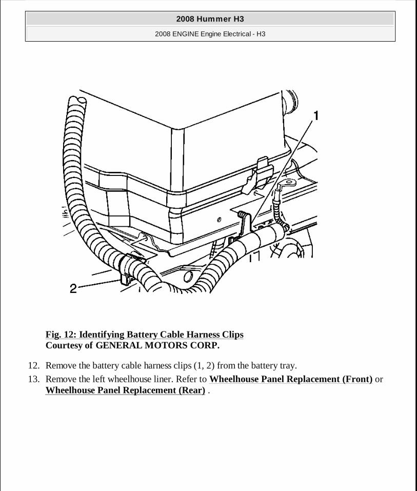
Fig. 12: Identifying Battery Cable Harness Clips Courtesy of GENERAL MOTORS CORP.
12. Remove the battery cable harness clips (1, 2) from the battery tray.
13. Remove the left wheelhouse liner. Refer to Wheelhouse Panel Replacement (Front) or Wheelhouse Panel Replacement (Rear) .
2008 Hummer H3
2008 ENGINE Engine Electrical - H3
MY
Sunday, March 29, 2009 10:52:06 PM Page 74 © 2005 Mitchell Repair Information Company, LLC.
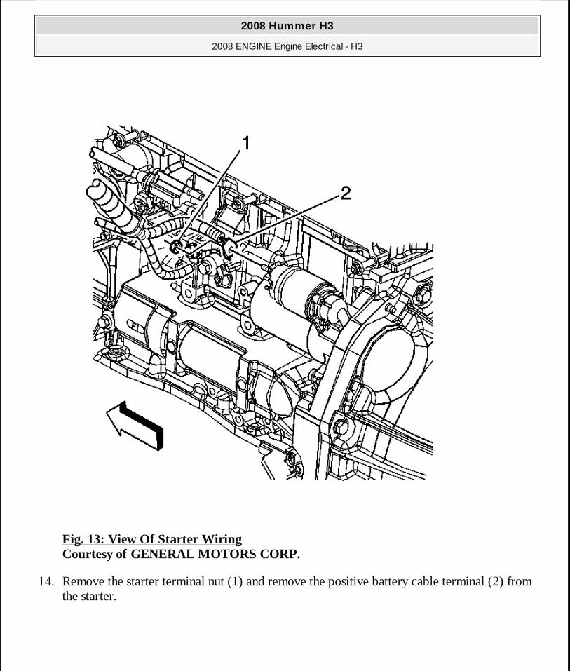
Fig. 13: View Of Starter Wiring Courtesy of GENERAL MOTORS CORP.
14. Remove the starter terminal nut (1) and remove the positive battery cable terminal (2) from the starter.
2008 Hummer H3
2008 ENGINE Engine Electrical - H3
MY
Sunday, March 29, 2009 10:52:06 PM Page 75 © 2005 Mitchell Repair Information Company, LLC.
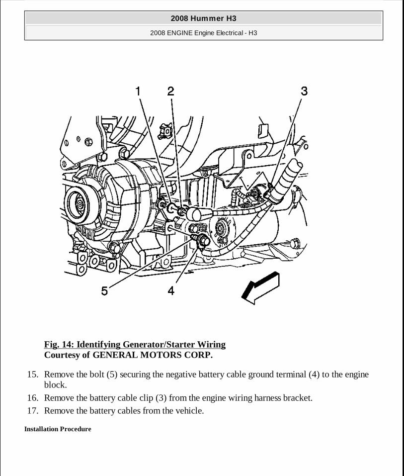
Fig. 14: Identifying Generator/Starter Wiring Courtesy of GENERAL MOTORS CORP.
15. Remove the bolt (5) securing the negative battery cable ground terminal (4) to the engine block.
16. Remove the battery cable clip (3) from the engine wiring harness bracket. 17. Remove the battery cables from the vehicle.
Installation Procedure
2008 Hummer H3
2008 ENGINE Engine Electrical - H3
MY
Sunday, March 29, 2009 10:52:06 PM Page 76 © 2005 Mitchell Repair Information Company, LLC.
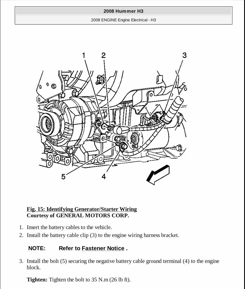
Fig. 15: Identifying Generator/Starter Wiring Courtesy of GENERAL MOTORS CORP.
1. Insert the battery cables to the vehicle. 2. Install the battery cable clip (3) to the engine wiring harness bracket.
3. Install the bolt (5) securing the negative battery cable ground terminal (4) to the engine block.
Tighten: Tighten the bolt to 35 N.m (26 lb ft).
NOTE: Refer to Fastener Notice .
2008 Hummer H3
2008 ENGINE Engine Electrical - H3
MY
Sunday, March 29, 2009 10:52:06 PM Page 77 © 2005 Mitchell Repair Information Company, LLC.
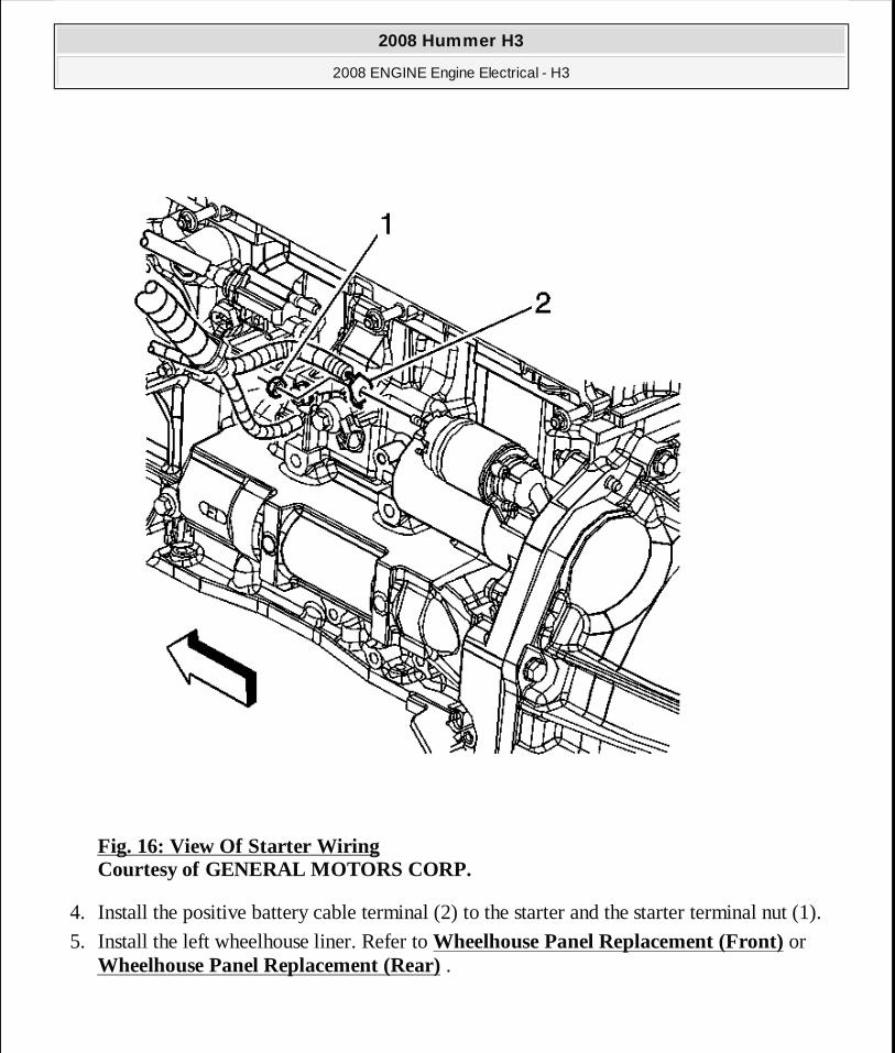
Fig. 16: View Of Starter Wiring Courtesy of GENERAL MOTORS CORP.
4. Install the positive battery cable terminal (2) to the starter and the starter terminal nut (1).
5. Install the left wheelhouse liner. Refer to Wheelhouse Panel Replacement (Front) or Wheelhouse Panel Replacement (Rear) .
2008 Hummer H3
2008 ENGINE Engine Electrical - H3
MY
Sunday, March 29, 2009 10:52:06 PM Page 78 © 2005 Mitchell Repair Information Company, LLC.
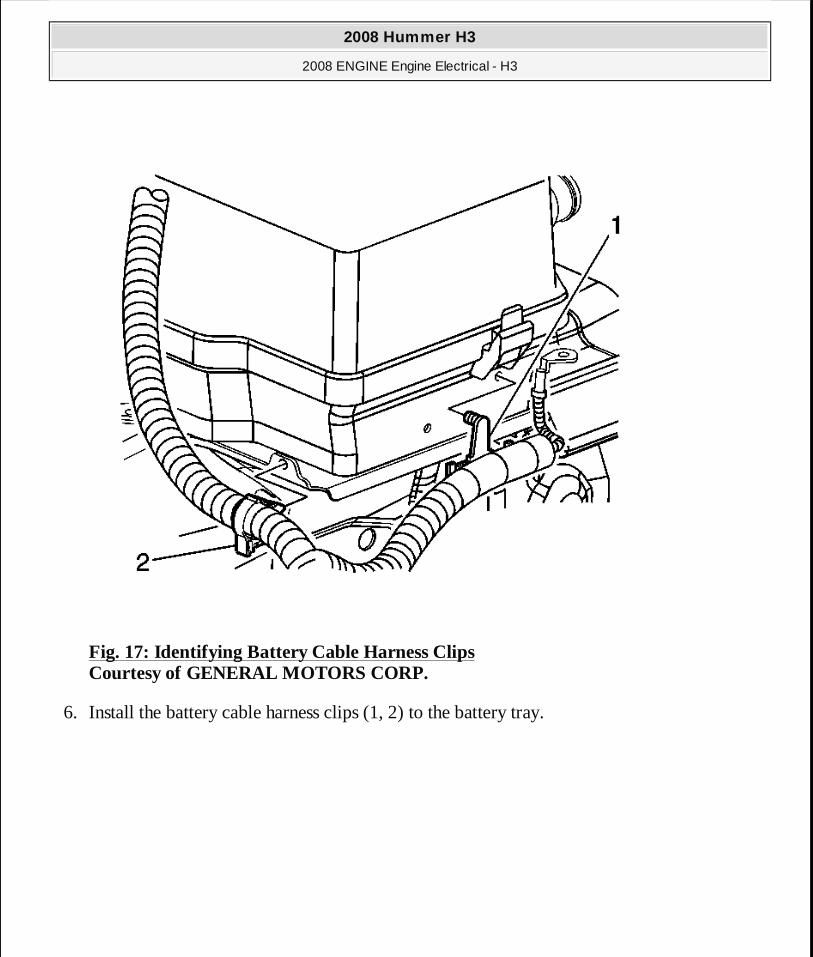
Fig. 17: Identifying Battery Cable Harness Clips Courtesy of GENERAL MOTORS CORP.
6. Install the battery cable harness clips (1, 2) to the battery tray.
2008 Hummer H3
2008 ENGINE Engine Electrical - H3
MY
Sunday, March 29, 2009 10:52:06 PM Page 79 © 2005 Mitchell Repair Information Company, LLC.
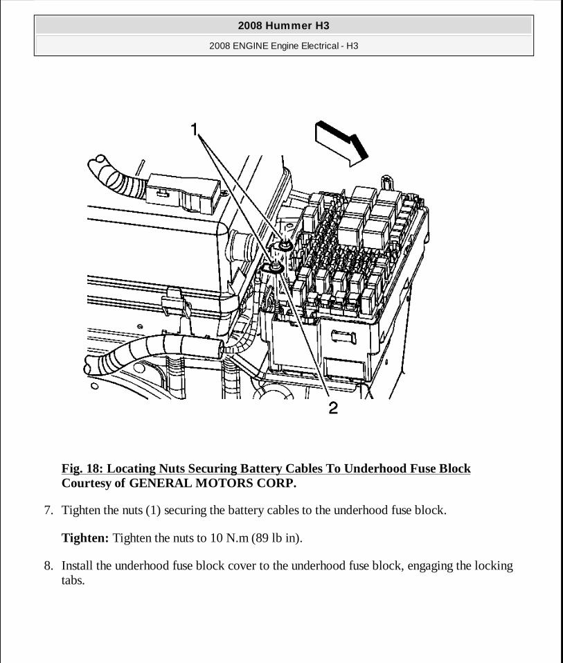
Fig. 18: Locating Nuts Securing Battery Cables To Underhood Fuse Block Courtesy of GENERAL MOTORS CORP.
7. Tighten the nuts (1) securing the battery cables to the underhood fuse block.
Tighten: Tighten the nuts to 10 N.m (89 lb in).
8. Install the underhood fuse block cover to the underhood fuse block, engaging the locking tabs.
2008 Hummer H3
2008 ENGINE Engine Electrical - H3
MY
Sunday, March 29, 2009 10:52:06 PM Page 80 © 2005 Mitchell Repair Information Company, LLC.
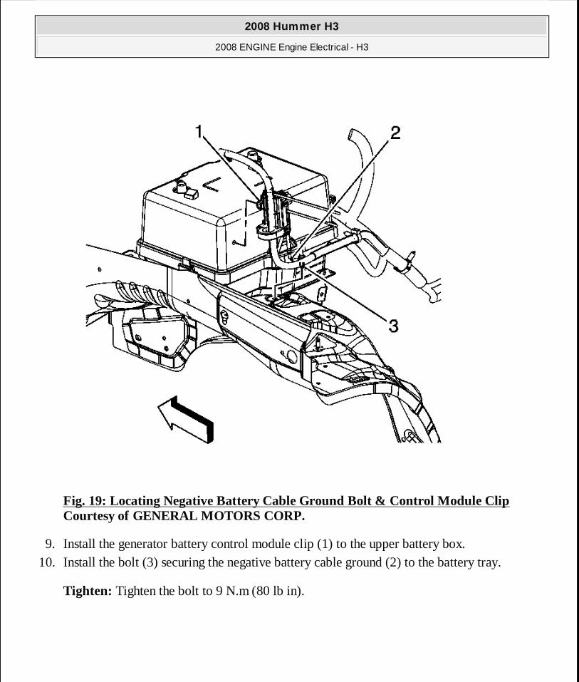
Fig. 19: Locating Negative Battery Cable Ground Bolt & Control Module Clip Courtesy of GENERAL MOTORS CORP.
9. Install the generator battery control module clip (1) to the upper battery box. 10. Install the bolt (3) securing the negative battery cable ground (2) to the battery tray.
Tighten: Tighten the bolt to 9 N.m (80 lb in).
2008 Hummer H3
2008 ENGINE Engine Electrical - H3
MY
Sunday, March 29, 2009 10:52:06 PM Page 81 © 2005 Mitchell Repair Information Company, LLC.

Fig. 20: Identifying Battery Cable Wiring Harness Connector Courtesy of GENERAL MOTORS CORP.
11. Connect the battery cable wiring harness electrical connector to the body wiring harness electrical connector.
2008 Hummer H3
2008 ENGINE Engine Electrical - H3
MY
Sunday, March 29, 2009 10:52:06 PM Page 82 © 2005 Mitchell Repair Information Company, LLC.
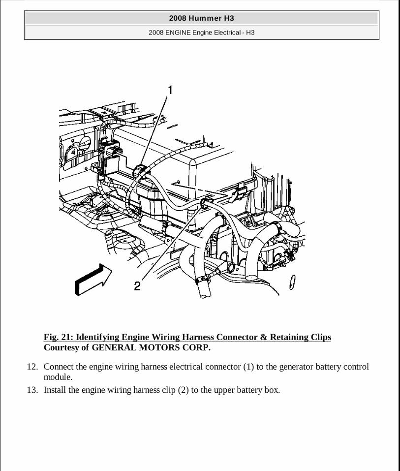
Fig. 21: Identifying Engine Wiring Harness Connector & Retaining Clips Courtesy of GENERAL MOTORS CORP.
12. Connect the engine wiring harness electrical connector (1) to the generator battery control module.
13. Install the engine wiring harness clip (2) to the upper battery box.
2008 Hummer H3
2008 ENGINE Engine Electrical - H3
MY
Sunday, March 29, 2009 10:52:06 PM Page 83 © 2005 Mitchell Repair Information Company, LLC.
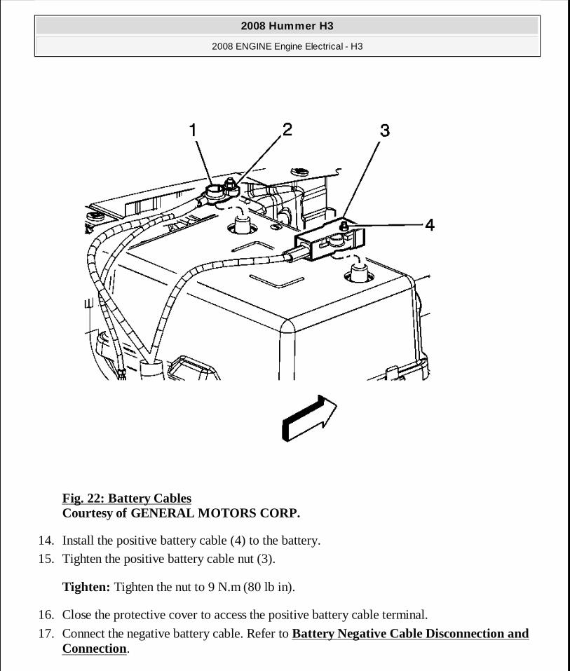
Fig. 22: Battery Cables Courtesy of GENERAL MOTORS CORP.
14. Install the positive battery cable (4) to the battery. 15. Tighten the positive battery cable nut (3).
Tighten: Tighten the nut to 9 N.m (80 lb in).
16. Close the protective cover to access the positive battery cable terminal.
17. Connect the negative battery cable. Refer to Battery Negative Cable Disconnection and Connection.
2008 Hummer H3
2008 ENGINE Engine Electrical - H3
MY
Sunday, March 29, 2009 10:52:06 PM Page 84 © 2005 Mitchell Repair Information Company, LLC.
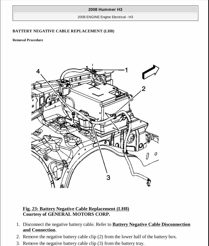
BATTERY NEGATIVE CABLE REPLACEMENT (LH8)
Removal Procedure
Fig. 23: Battery Negative Cable Replacement (LH8) Courtesy of GENERAL MOTORS CORP.
1. Disconnect the negative battery cable. Refer to Battery Negative Cable Disconnection and Connection.
2. Remove the negative battery cable clip (2) from the lower half of the battery box. 3. Remove the negative battery cable clip (3) from the battery tray.
2008 Hummer H3
2008 ENGINE Engine Electrical - H3
MY
Sunday, March 29, 2009 10:52:06 PM Page 85 © 2005 Mitchell Repair Information Company, LLC.
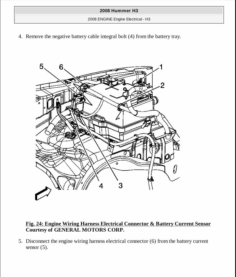
4. Remove the negative battery cable integral bolt (4) from the battery tray.
Fig. 24: Engine Wiring Harness Electrical Connector & Battery Current Sensor Courtesy of GENERAL MOTORS CORP.
5. Disconnect the engine wiring harness electrical connector (6) from the battery current sensor (5).
2008 Hummer H3
2008 ENGINE Engine Electrical - H3
MY
Sunday, March 29, 2009 10:52:07 PM Page 86 © 2005 Mitchell Repair Information Company, LLC.
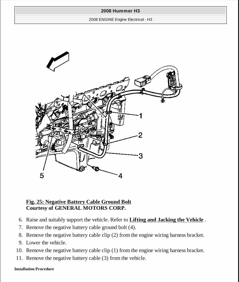
Fig. 25: Negative Battery Cable Ground Bolt Courtesy of GENERAL MOTORS CORP.
6. Raise and suitably support the vehicle. Refer to Lifting and Jacking the Vehicle . 7. Remove the negative battery cable ground bolt (4). 8. Remove the negative battery cable clip (2) from the engine wiring harness bracket. 9. Lower the vehicle.
10. Remove the negative battery cable clip (1) from the engine wiring harness bracket. 11. Remove the negative battery cable (3) from the vehicle.
Installation Procedure
2008 Hummer H3
2008 ENGINE Engine Electrical - H3
MY
Sunday, March 29, 2009 10:52:07 PM Page 87 © 2005 Mitchell Repair Information Company, LLC.
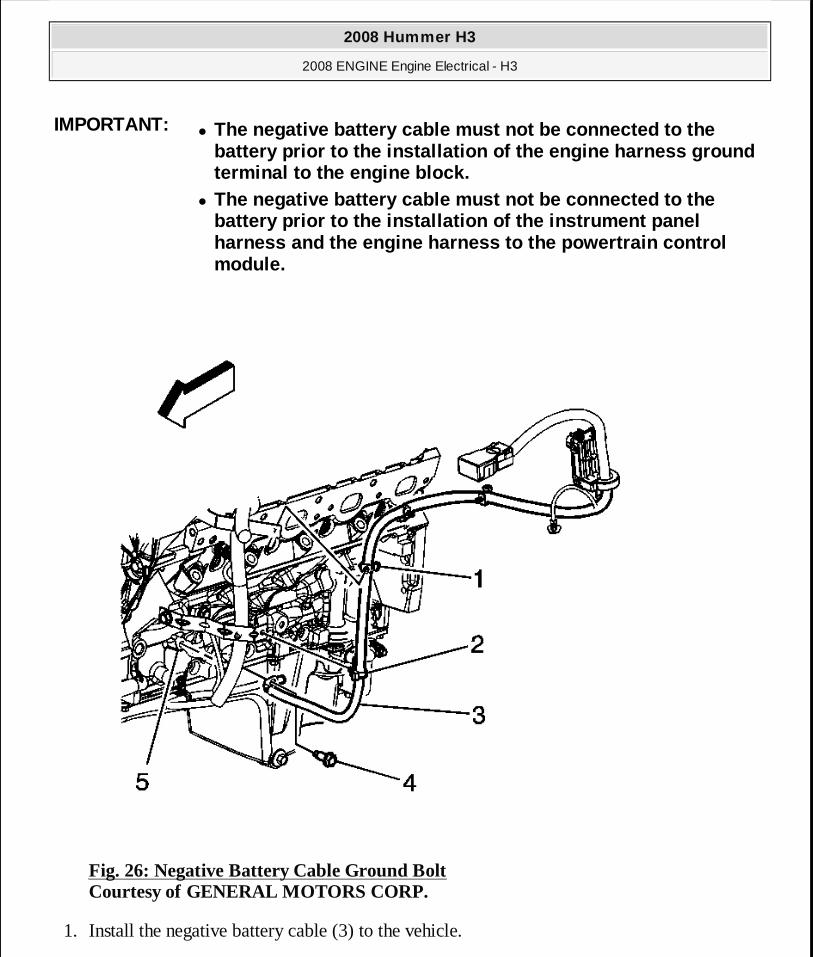
Fig. 26: Negative Battery Cable Ground Bolt Courtesy of GENERAL MOTORS CORP.
1. Install the negative battery cable (3) to the vehicle.
IMPORTANT:� The negative battery cable must not be connected to the
battery prior to the installation of the engine har ness ground terminal to the engine block.
� The negative battery cable must not be connected to the battery prior to the installation of the instrument panel harness and the engine harness to the powertrain co ntrol module.
2008 Hummer H3
2008 ENGINE Engine Electrical - H3
MY
Sunday, March 29, 2009 10:52:07 PM Page 88 © 2005 Mitchell Repair Information Company, LLC.
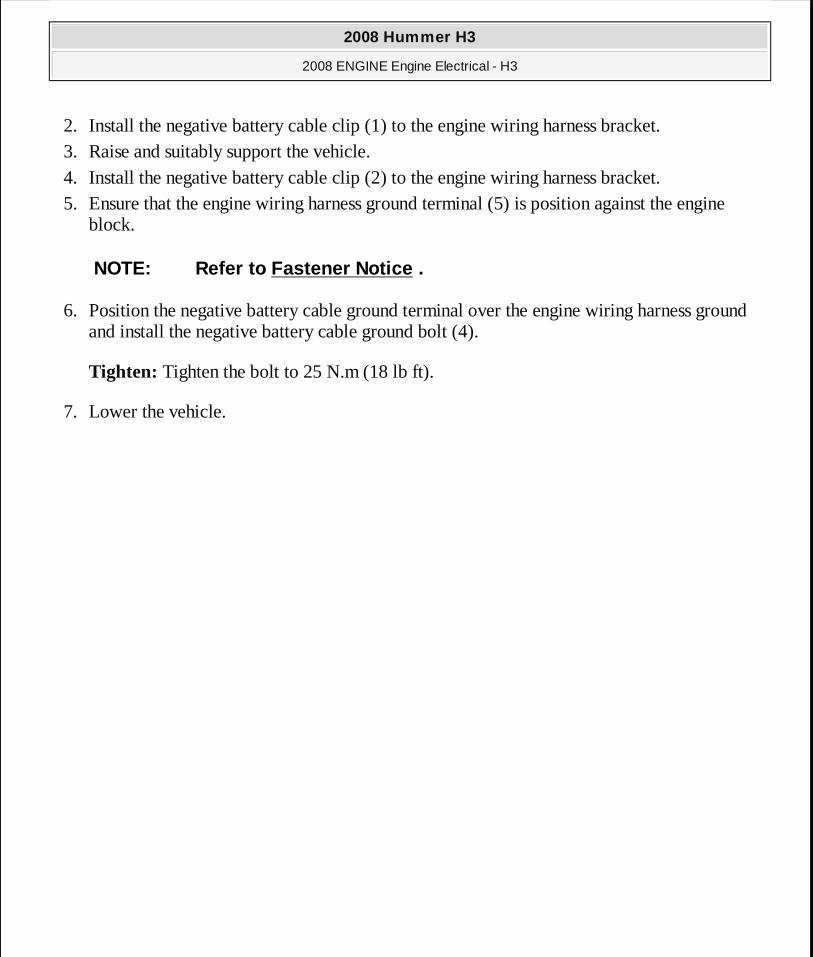
2. Install the negative battery cable clip (1) to the engine wiring harness bracket. 3. Raise and suitably support the vehicle. 4. Install the negative battery cable clip (2) to the engine wiring harness bracket. 5. Ensure that the engine wiring harness ground terminal (5) is position against the engine
block.
6. Position the negative battery cable ground terminal over the engine wiring harness ground and install the negative battery cable ground bolt (4).
Tighten: Tighten the bolt to 25 N.m (18 lb ft).
7. Lower the vehicle.
NOTE: Refer to Fastener Notice .
2008 Hummer H3
2008 ENGINE Engine Electrical - H3
MY
Sunday, March 29, 2009 10:52:07 PM Page 89 © 2005 Mitchell Repair Information Company, LLC.
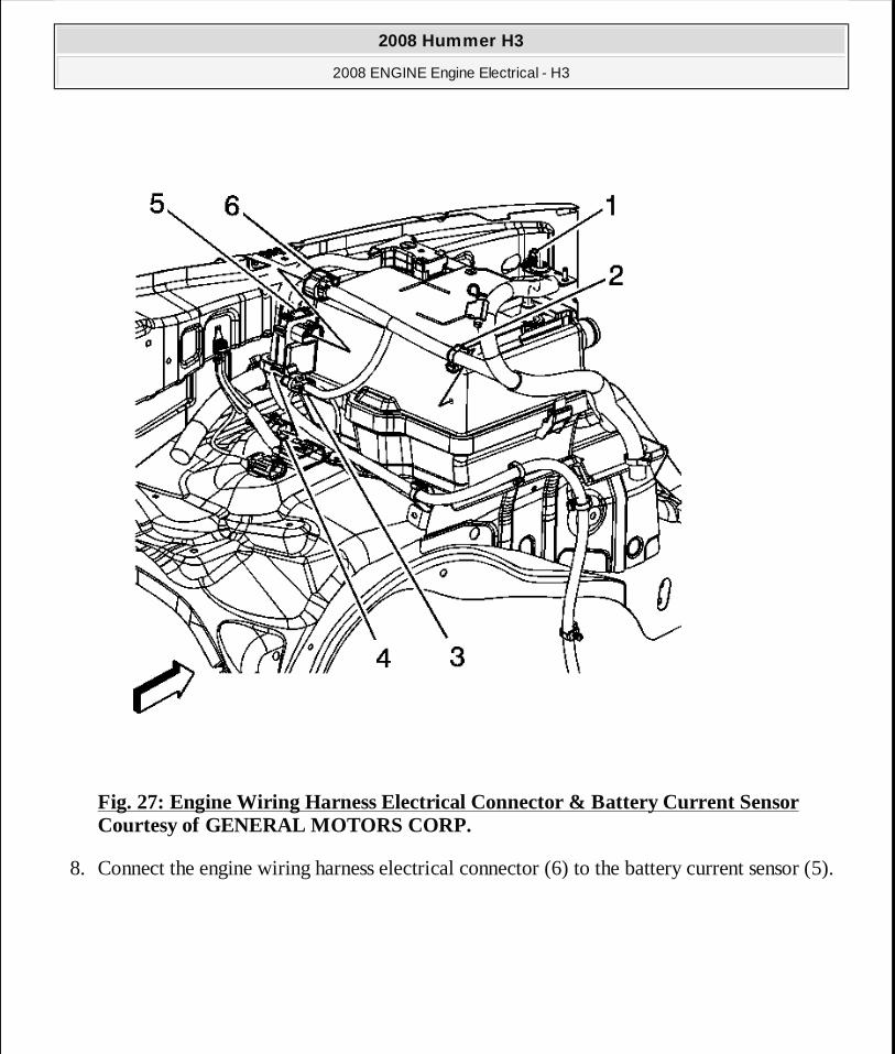
Fig. 27: Engine Wiring Harness Electrical Connector & Battery Current Sensor Courtesy of GENERAL MOTORS CORP.
8. Connect the engine wiring harness electrical connector (6) to the battery current sensor (5).
2008 Hummer H3
2008 ENGINE Engine Electrical - H3
MY
Sunday, March 29, 2009 10:52:07 PM Page 90 © 2005 Mitchell Repair Information Company, LLC.
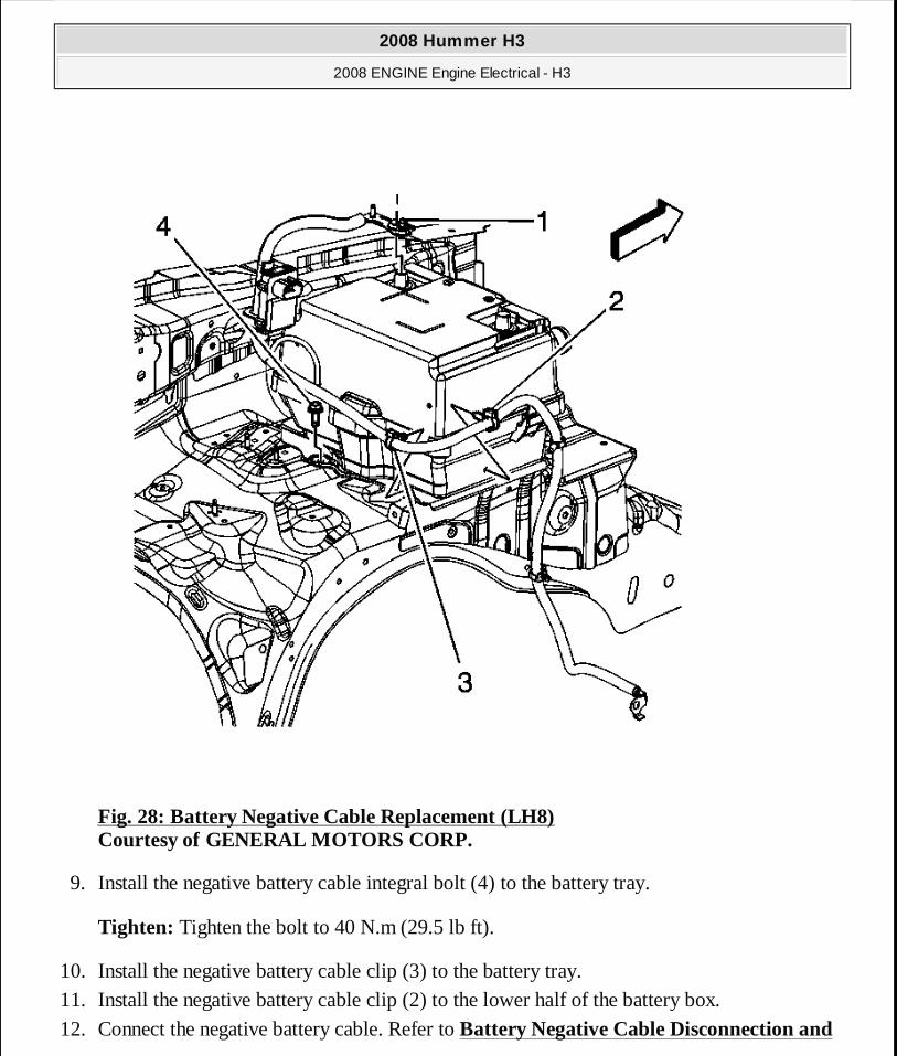
Fig. 28: Battery Negative Cable Replacement (LH8) Courtesy of GENERAL MOTORS CORP.
9. Install the negative battery cable integral bolt (4) to the battery tray.
Tighten: Tighten the bolt to 40 N.m (29.5 lb ft).
10. Install the negative battery cable clip (3) to the battery tray. 11. Install the negative battery cable clip (2) to the lower half of the battery box.
12. Connect the negative battery cable. Refer to Battery Negative Cable Disconnection and
2008 Hummer H3
2008 ENGINE Engine Electrical - H3
MY
Sunday, March 29, 2009 10:52:07 PM Page 91 © 2005 Mitchell Repair Information Company, LLC.
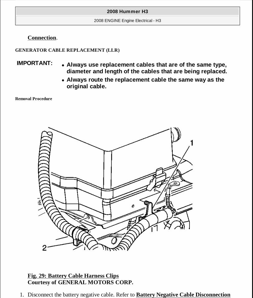
Connection.
GENERATOR CABLE REPLACEMENT (LLR)
Removal Procedure
Fig. 29: Battery Cable Harness Clips Courtesy of GENERAL MOTORS CORP.
1. Disconnect the battery negative cable. Refer to Battery Negative Cable Disconnection
IMPORTANT:� Always use replacement cables that are of the same type,
diameter and length of the cables that are being re placed. � Always route the replacement cable the same way as the
original cable.
2008 Hummer H3
2008 ENGINE Engine Electrical - H3
MY
Sunday, March 29, 2009 10:52:07 PM Page 92 © 2005 Mitchell Repair Information Company, LLC.
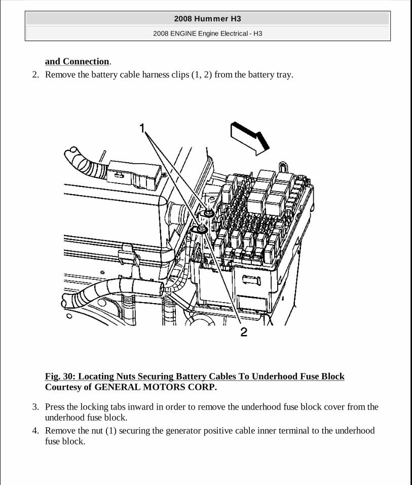
and Connection. 2. Remove the battery cable harness clips (1, 2) from the battery tray.
Fig. 30: Locating Nuts Securing Battery Cables To Underhood Fuse Block Courtesy of GENERAL MOTORS CORP.
3. Press the locking tabs inward in order to remove the underhood fuse block cover from the underhood fuse block.
4. Remove the nut (1) securing the generator positive cable inner terminal to the underhood fuse block.
2008 Hummer H3
2008 ENGINE Engine Electrical - H3
MY
Sunday, March 29, 2009 10:52:07 PM Page 93 © 2005 Mitchell Repair Information Company, LLC.

Fig. 31: Generator/Starter Wiring Courtesy of GENERAL MOTORS CORP.
5. Remove the left front wheelhouse liner. Refer to Wheelhouse Panel Replacement (Front) or Wheelhouse Panel Replacement (Rear) .
6. Reposition the protective boot from the generator output BAT terminal for access. 7. Remove the generator output BAT terminal nut (2) and disconnect the generator positive
lead (1) from the generator. 8. Remove the positive cable clip (3) from the engine wiring harness bracket. 9. Remove the generator positive cable from the battery cables harness conduit.
Installation Procedure
2008 Hummer H3
2008 ENGINE Engine Electrical - H3
MY
Sunday, March 29, 2009 10:52:07 PM Page 94 © 2005 Mitchell Repair Information Company, LLC.
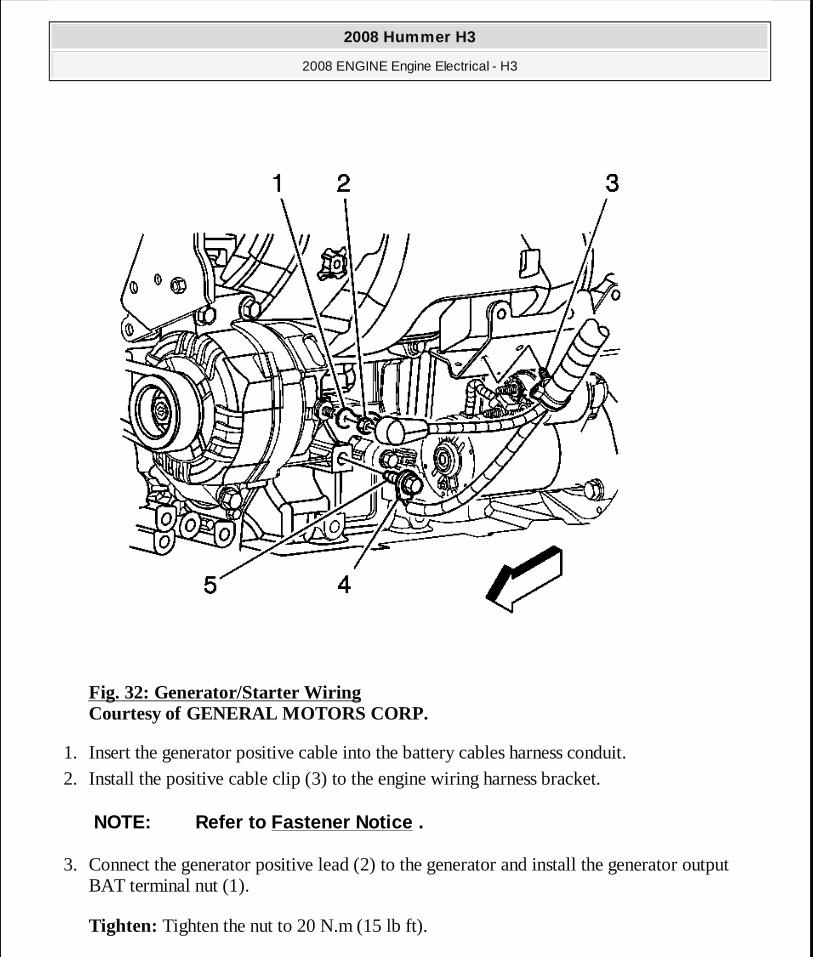
Fig. 32: Generator/Starter Wiring Courtesy of GENERAL MOTORS CORP.
1. Insert the generator positive cable into the battery cables harness conduit. 2. Install the positive cable clip (3) to the engine wiring harness bracket.
3. Connect the generator positive lead (2) to the generator and install the generator output BAT terminal nut (1).
Tighten: Tighten the nut to 20 N.m (15 lb ft).
NOTE: Refer to Fastener Notice .
2008 Hummer H3
2008 ENGINE Engine Electrical - H3
MY
Sunday, March 29, 2009 10:52:07 PM Page 95 © 2005 Mitchell Repair Information Company, LLC.
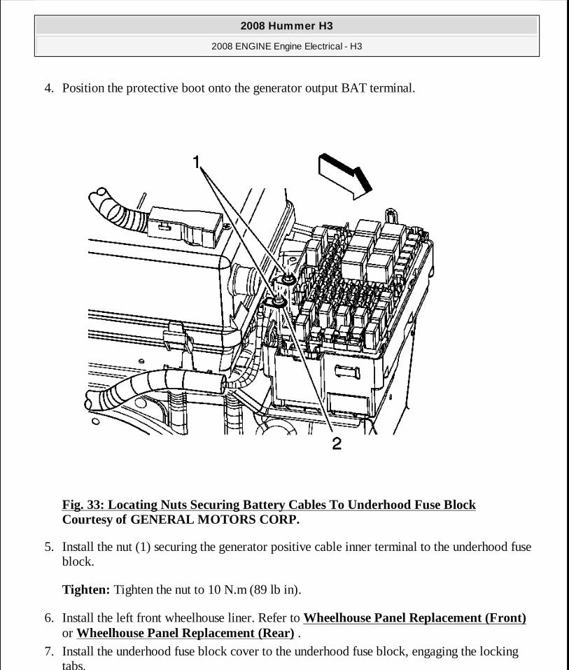
4. Position the protective boot onto the generator output BAT terminal.
Fig. 33: Locating Nuts Securing Battery Cables To Underhood Fuse Block Courtesy of GENERAL MOTORS CORP.
5. Install the nut (1) securing the generator positive cable inner terminal to the underhood fuse block.
Tighten: Tighten the nut to 10 N.m (89 lb in).
6. Install the left front wheelhouse liner. Refer to Wheelhouse Panel Replacement (Front) or Wheelhouse Panel Replacement (Rear) .
7. Install the underhood fuse block cover to the underhood fuse block, engaging the locking tabs.
2008 Hummer H3
2008 ENGINE Engine Electrical - H3
MY
Sunday, March 29, 2009 10:52:07 PM Page 96 © 2005 Mitchell Repair Information Company, LLC.
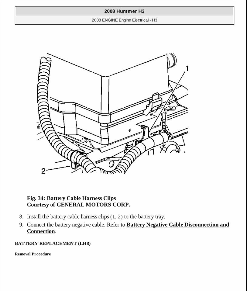
Fig. 34: Battery Cable Harness Clips Courtesy of GENERAL MOTORS CORP.
8. Install the battery cable harness clips (1, 2) to the battery tray.
9. Connect the battery negative cable. Refer to Battery Negative Cable Disconnection and Connection.
BATTERY REPLACEMENT (LH8)
Removal Procedure
2008 Hummer H3
2008 ENGINE Engine Electrical - H3
MY
Sunday, March 29, 2009 10:52:07 PM Page 97 © 2005 Mitchell Repair Information Company, LLC.
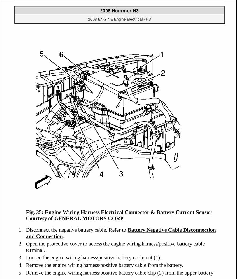
Fig. 35: Engine Wiring Harness Electrical Connector & Battery Current Sensor Courtesy of GENERAL MOTORS CORP.
1. Disconnect the negative battery cable. Refer to Battery Negative Cable Disconnection and Connection.
2. Open the protective cover to access the engine wiring harness/positive battery cable terminal.
3. Loosen the engine wiring harness/positive battery cable nut (1). 4. Remove the engine wiring harness/positive battery cable from the battery. 5. Remove the engine wiring harness/positive battery cable clip (2) from the upper battery
2008 Hummer H3
2008 ENGINE Engine Electrical - H3
MY
Sunday, March 29, 2009 10:52:07 PM Page 98 © 2005 Mitchell Repair Information Company, LLC.
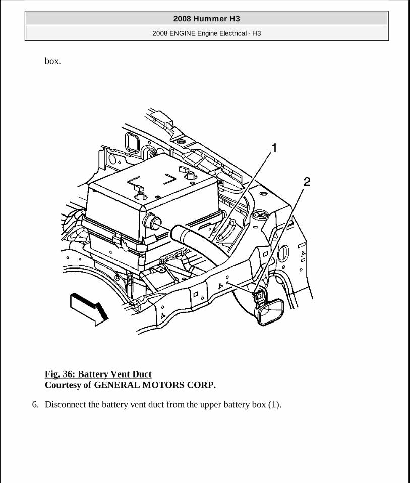
box.
Fig. 36: Battery Vent Duct Courtesy of GENERAL MOTORS CORP.
6. Disconnect the battery vent duct from the upper battery box (1).
2008 Hummer H3
2008 ENGINE Engine Electrical - H3
MY
Sunday, March 29, 2009 10:52:07 PM Page 99 © 2005 Mitchell Repair Information Company, LLC.

Fig. 37: Upper Battery Box Cover Courtesy of GENERAL MOTORS CORP.
7. Press the locking tabs (1) inward in order to remove the upper battery box (2) from the lower battery box.
2008 Hummer H3
2008 ENGINE Engine Electrical - H3
MY
Sunday, March 29, 2009 10:52:07 PM Page 100 © 2005 Mitchell Repair Information Company, LLC.

Fig. 38: Battery Strap Pin Courtesy of GENERAL MOTORS CORP.
8. Remove the battery retainer nut (2).
2008 Hummer H3
2008 ENGINE Engine Electrical - H3
MY
Sunday, March 29, 2009 10:52:07 PM Page 101 © 2005 Mitchell Repair Information Company, LLC.
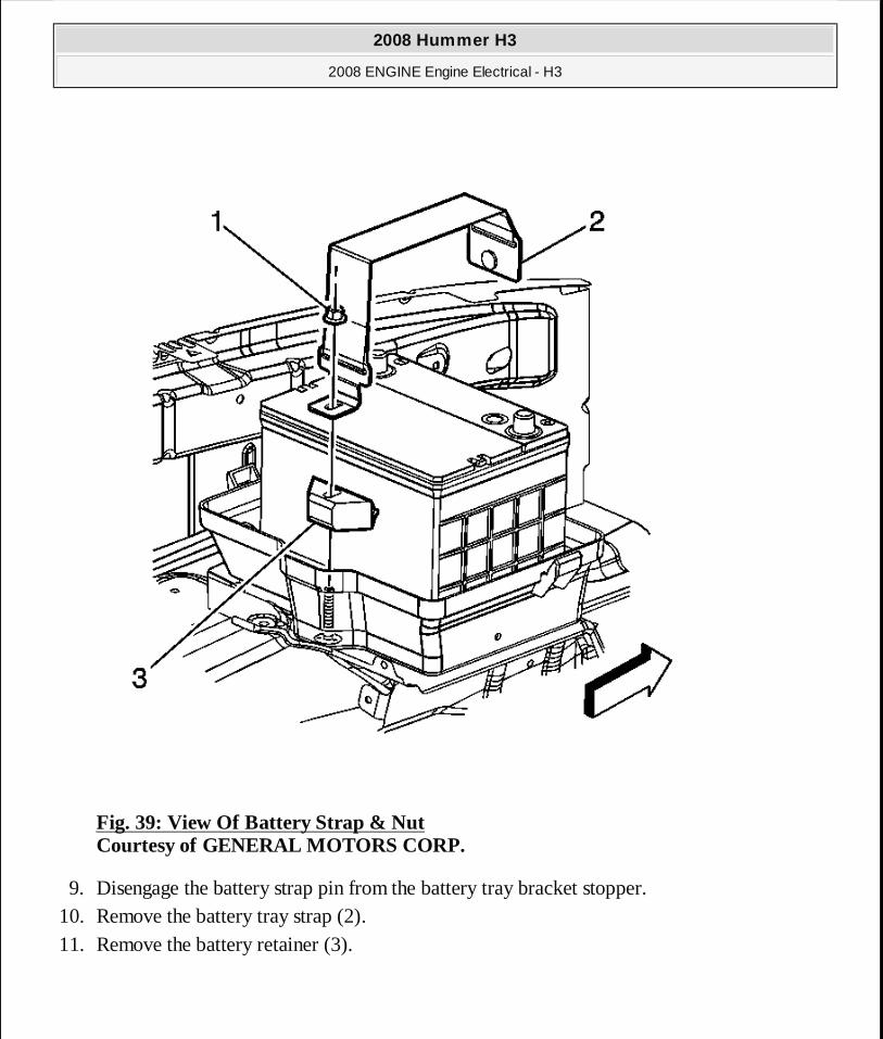
Fig. 39: View Of Battery Strap & Nut Courtesy of GENERAL MOTORS CORP.
9. Disengage the battery strap pin from the battery tray bracket stopper. 10. Remove the battery tray strap (2). 11. Remove the battery retainer (3).
2008 Hummer H3
2008 ENGINE Engine Electrical - H3
MY
Sunday, March 29, 2009 10:52:07 PM Page 102 © 2005 Mitchell Repair Information Company, LLC.

Fig. 40: Battery & Battery Box Courtesy of GENERAL MOTORS CORP.
12. Remove the battery from the lower battery box.
Installation Procedure
2008 Hummer H3
2008 ENGINE Engine Electrical - H3
MY
Sunday, March 29, 2009 10:52:07 PM Page 103 © 2005 Mitchell Repair Information Company, LLC.
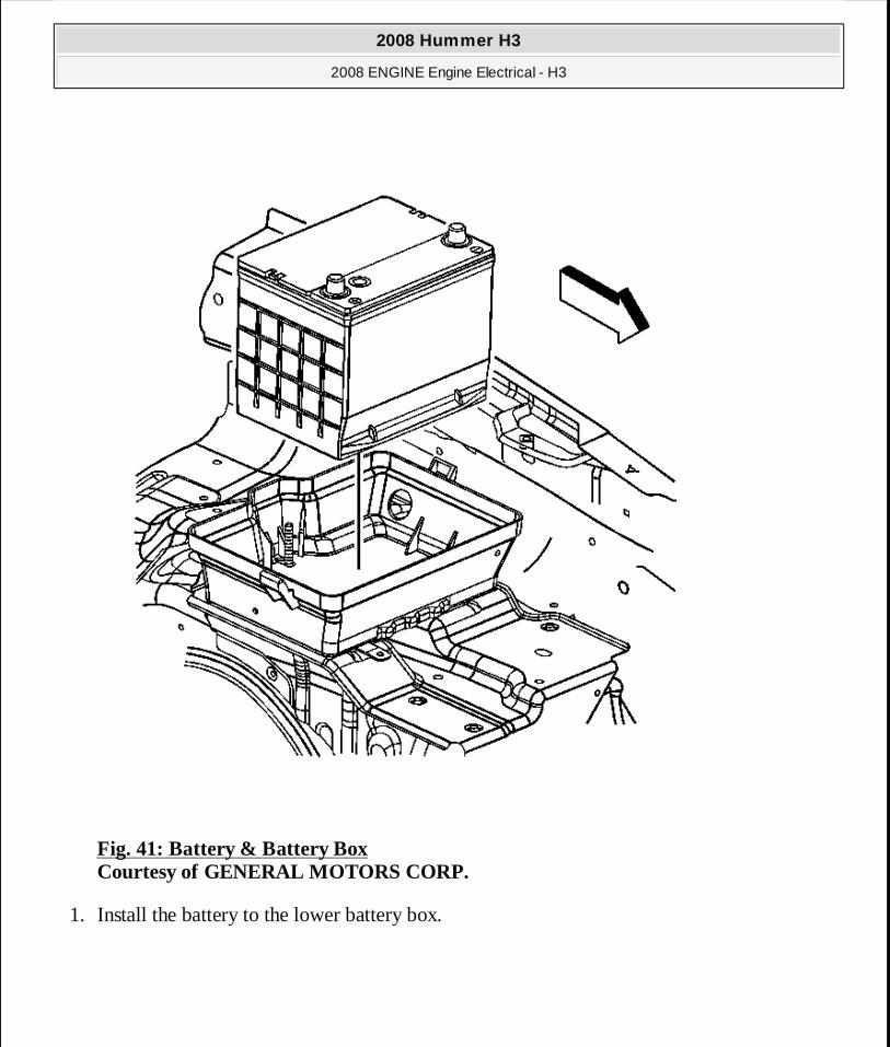
Fig. 41: Battery & Battery Box Courtesy of GENERAL MOTORS CORP.
1. Install the battery to the lower battery box.
2008 Hummer H3
2008 ENGINE Engine Electrical - H3
MY
Sunday, March 29, 2009 10:52:07 PM Page 104 © 2005 Mitchell Repair Information Company, LLC.
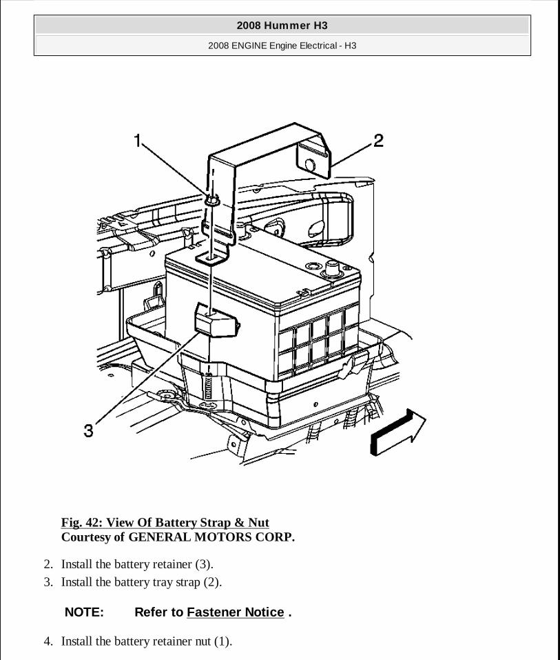
Fig. 42: View Of Battery Strap & Nut Courtesy of GENERAL MOTORS CORP.
2. Install the battery retainer (3). 3. Install the battery tray strap (2).
4. Install the battery retainer nut (1).
NOTE: Refer to Fastener Notice .
2008 Hummer H3
2008 ENGINE Engine Electrical - H3
MY
Sunday, March 29, 2009 10:52:07 PM Page 105 © 2005 Mitchell Repair Information Company, LLC.
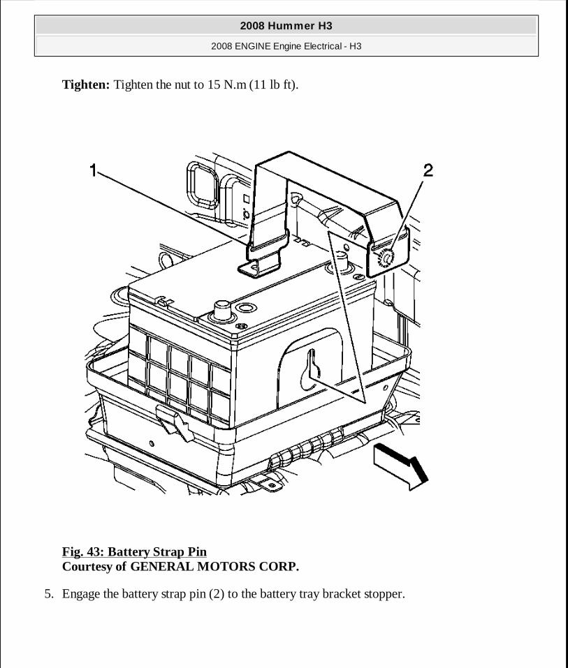
Tighten: Tighten the nut to 15 N.m (11 lb ft).
Fig. 43: Battery Strap Pin Courtesy of GENERAL MOTORS CORP.
5. Engage the battery strap pin (2) to the battery tray bracket stopper.
2008 Hummer H3
2008 ENGINE Engine Electrical - H3
MY
Sunday, March 29, 2009 10:52:07 PM Page 106 © 2005 Mitchell Repair Information Company, LLC.
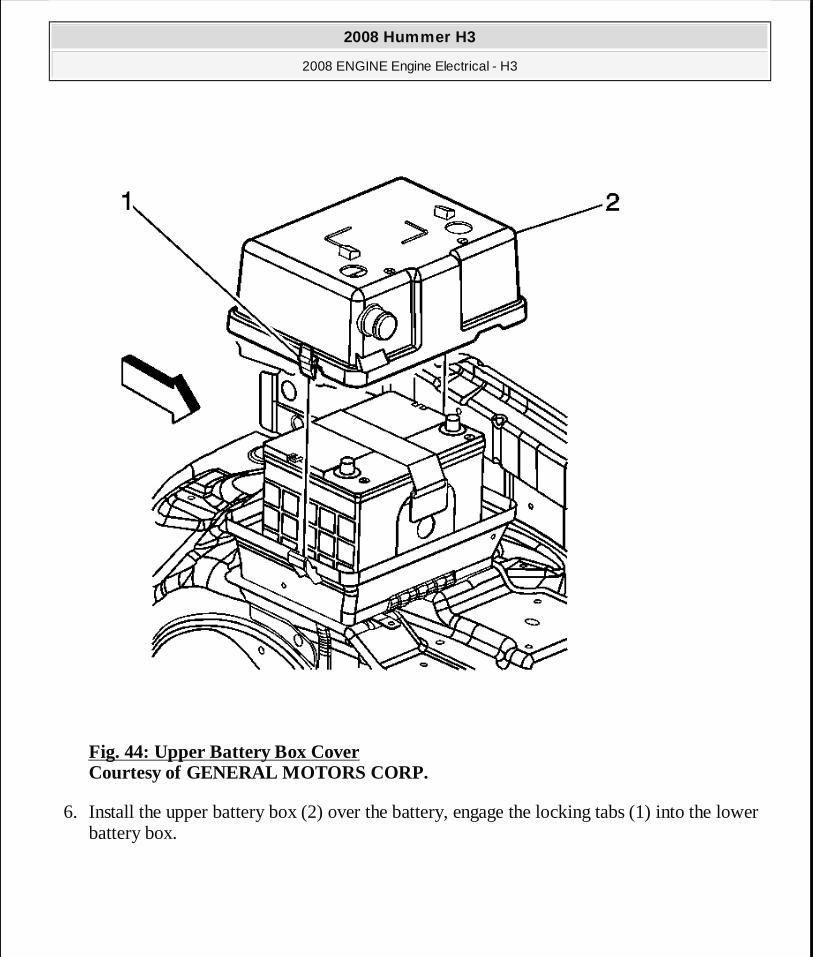
Fig. 44: Upper Battery Box Cover Courtesy of GENERAL MOTORS CORP.
6. Install the upper battery box (2) over the battery, engage the locking tabs (1) into the lower battery box.
2008 Hummer H3
2008 ENGINE Engine Electrical - H3
MY
Sunday, March 29, 2009 10:52:07 PM Page 107 © 2005 Mitchell Repair Information Company, LLC.
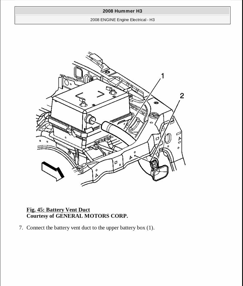
Fig. 45: Battery Vent Duct Courtesy of GENERAL MOTORS CORP.
7. Connect the battery vent duct to the upper battery box (1).
2008 Hummer H3
2008 ENGINE Engine Electrical - H3
MY
Sunday, March 29, 2009 10:52:07 PM Page 108 © 2005 Mitchell Repair Information Company, LLC.
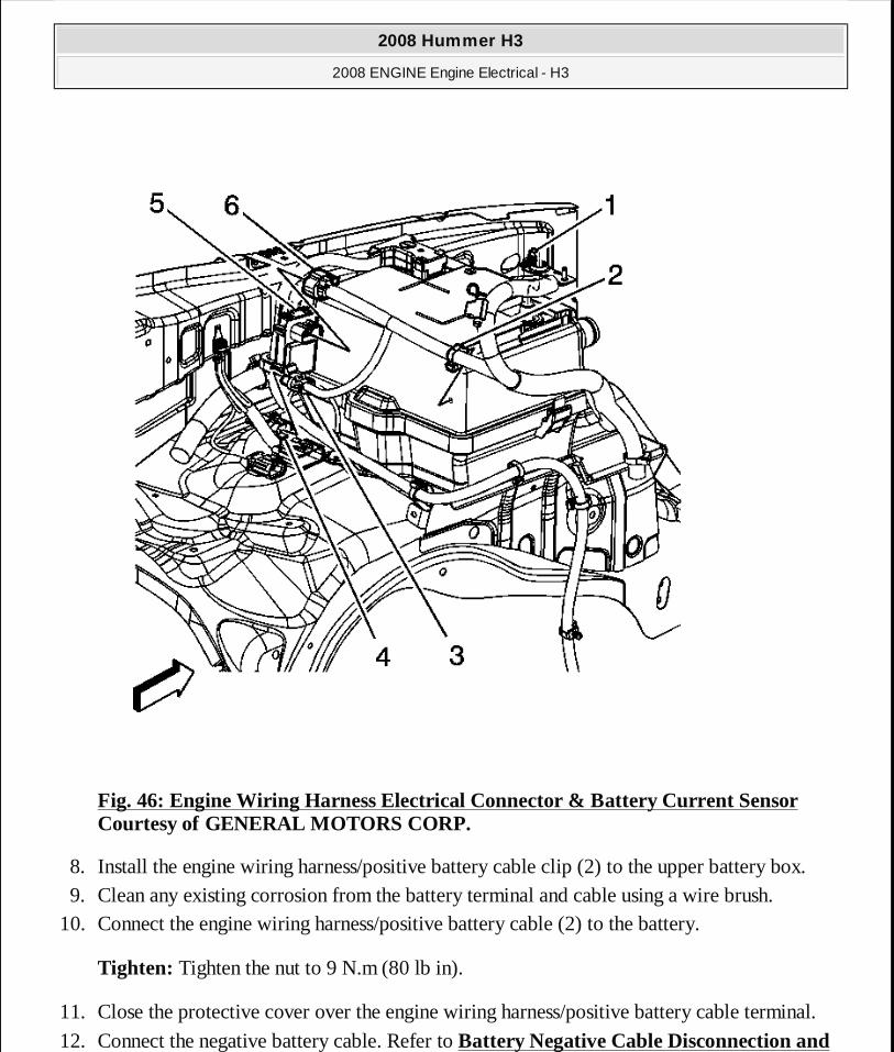
Fig. 46: Engine Wiring Harness Electrical Connector & Battery Current Sensor Courtesy of GENERAL MOTORS CORP.
8. Install the engine wiring harness/positive battery cable clip (2) to the upper battery box. 9. Clean any existing corrosion from the battery terminal and cable using a wire brush.
10. Connect the engine wiring harness/positive battery cable (2) to the battery.
Tighten: Tighten the nut to 9 N.m (80 lb in).
11. Close the protective cover over the engine wiring harness/positive battery cable terminal.
12. Connect the negative battery cable. Refer to Battery Negative Cable Disconnection and
2008 Hummer H3
2008 ENGINE Engine Electrical - H3
MY
Sunday, March 29, 2009 10:52:07 PM Page 109 © 2005 Mitchell Repair Information Company, LLC.
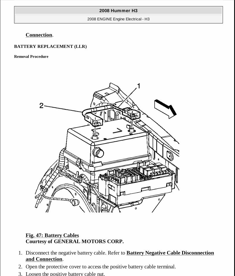
Connection.
BATTERY REPLACEMENT (LLR)
Removal Procedure
Fig. 47: Battery Cables Courtesy of GENERAL MOTORS CORP.
1. Disconnect the negative battery cable. Refer to Battery Negative Cable Disconnection and Connection.
2. Open the protective cover to access the positive battery cable terminal. 3. Loosen the positive battery cable nut.
2008 Hummer H3
2008 ENGINE Engine Electrical - H3
MY
Sunday, March 29, 2009 10:52:07 PM Page 110 © 2005 Mitchell Repair Information Company, LLC.
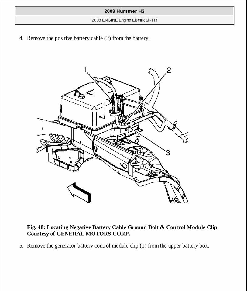
4. Remove the positive battery cable (2) from the battery.
Fig. 48: Locating Negative Battery Cable Ground Bolt & Control Module Clip Courtesy of GENERAL MOTORS CORP.
5. Remove the generator battery control module clip (1) from the upper battery box.
2008 Hummer H3
2008 ENGINE Engine Electrical - H3
MY
Sunday, March 29, 2009 10:52:07 PM Page 111 © 2005 Mitchell Repair Information Company, LLC.
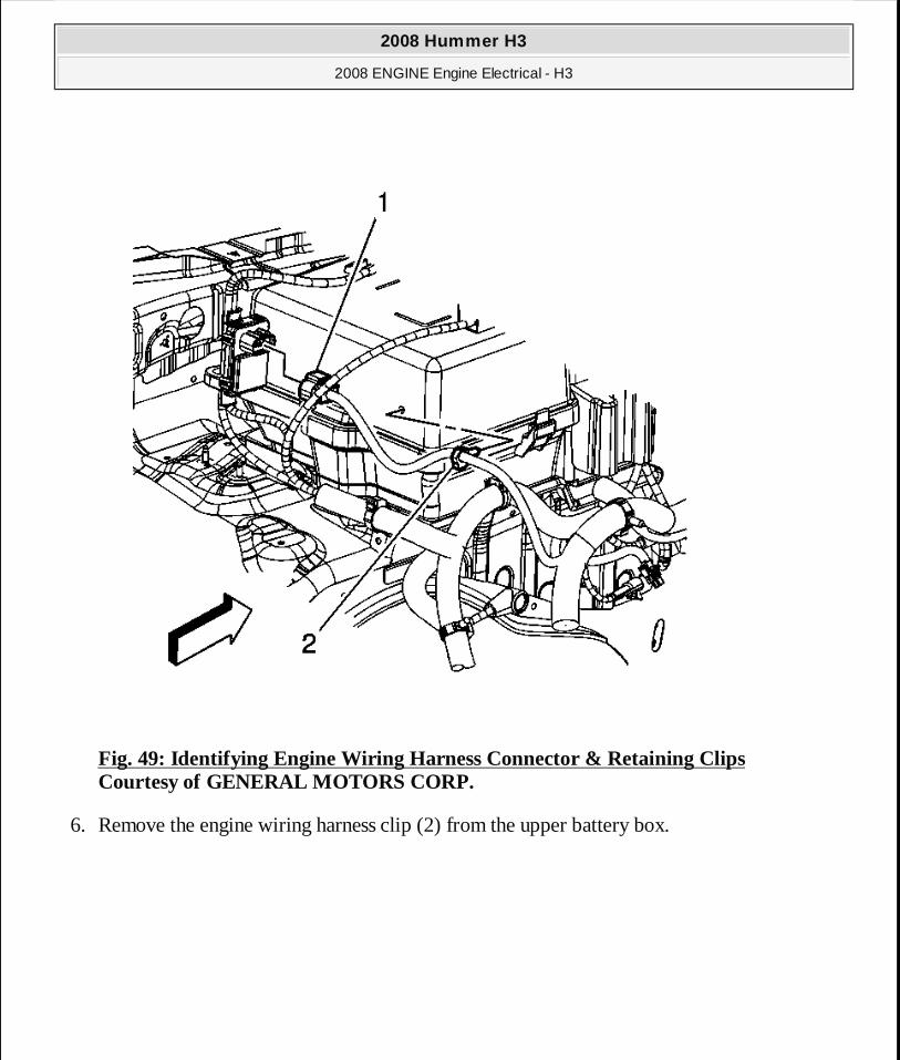
Fig. 49: Identifying Engine Wiring Harness Connector & Retaining Clips Courtesy of GENERAL MOTORS CORP.
6. Remove the engine wiring harness clip (2) from the upper battery box.
2008 Hummer H3
2008 ENGINE Engine Electrical - H3
MY
Sunday, March 29, 2009 10:52:07 PM Page 112 © 2005 Mitchell Repair Information Company, LLC.

Fig. 50: Battery Vent Duct Courtesy of GENERAL MOTORS CORP.
7. Disconnect the battery vent duct from the upper battery box (1).
2008 Hummer H3
2008 ENGINE Engine Electrical - H3
MY
Sunday, March 29, 2009 10:52:07 PM Page 113 © 2005 Mitchell Repair Information Company, LLC.
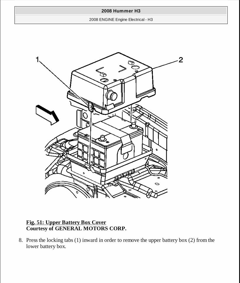
Fig. 51: Upper Battery Box Cover Courtesy of GENERAL MOTORS CORP.
8. Press the locking tabs (1) inward in order to remove the upper battery box (2) from the lower battery box.
2008 Hummer H3
2008 ENGINE Engine Electrical - H3
MY
Sunday, March 29, 2009 10:52:07 PM Page 114 © 2005 Mitchell Repair Information Company, LLC.
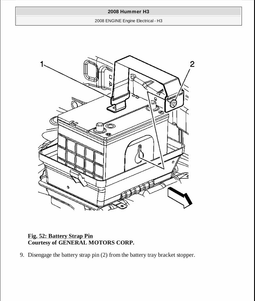
Fig. 52: Battery Strap Pin Courtesy of GENERAL MOTORS CORP.
9. Disengage the battery strap pin (2) from the battery tray bracket stopper.
2008 Hummer H3
2008 ENGINE Engine Electrical - H3
MY
Sunday, March 29, 2009 10:52:07 PM Page 115 © 2005 Mitchell Repair Information Company, LLC.
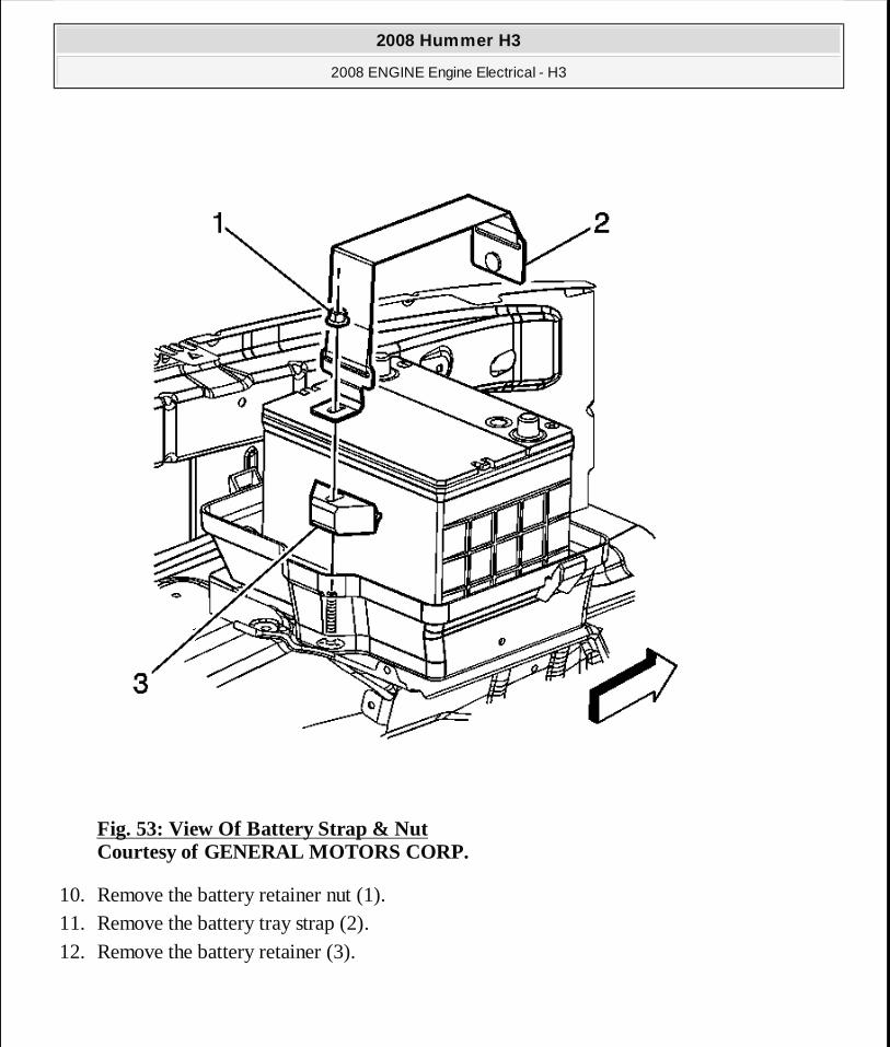
Fig. 53: View Of Battery Strap & Nut Courtesy of GENERAL MOTORS CORP.
10. Remove the battery retainer nut (1). 11. Remove the battery tray strap (2). 12. Remove the battery retainer (3).
2008 Hummer H3
2008 ENGINE Engine Electrical - H3
MY
Sunday, March 29, 2009 10:52:07 PM Page 116 © 2005 Mitchell Repair Information Company, LLC.

Fig. 54: Battery & Battery Box Courtesy of GENERAL MOTORS CORP.
13. Remove the battery from the lower battery box.
Installation Procedure
2008 Hummer H3
2008 ENGINE Engine Electrical - H3
MY
Sunday, March 29, 2009 10:52:07 PM Page 117 © 2005 Mitchell Repair Information Company, LLC.

Fig. 55: Battery & Battery Box Courtesy of GENERAL MOTORS CORP.
1. Install the battery to the lower battery box.
2008 Hummer H3
2008 ENGINE Engine Electrical - H3
MY
Sunday, March 29, 2009 10:52:08 PM Page 118 © 2005 Mitchell Repair Information Company, LLC.

Fig. 56: View Of Battery Strap & Nut Courtesy of GENERAL MOTORS CORP.
2. Install the battery retainer (3). 3. Install the battery tray strap (2).
4. Install the battery retainer nut (1).
NOTE: Refer to Fastener Notice .
2008 Hummer H3
2008 ENGINE Engine Electrical - H3
MY
Sunday, March 29, 2009 10:52:08 PM Page 119 © 2005 Mitchell Repair Information Company, LLC.
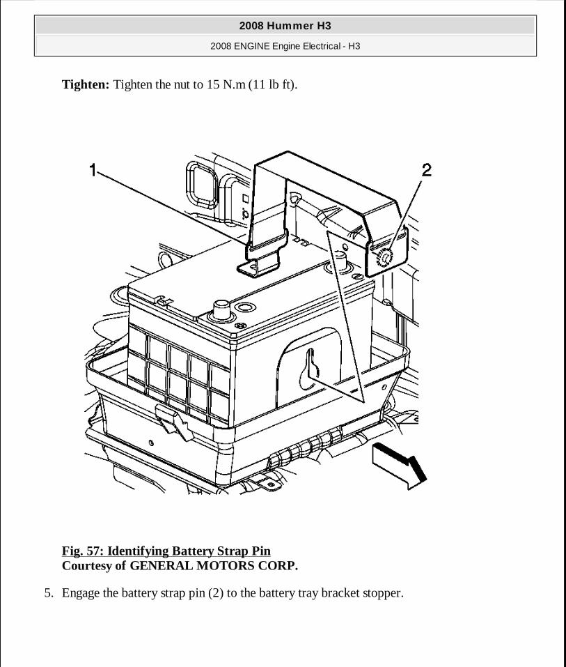
Tighten: Tighten the nut to 15 N.m (11 lb ft).
Fig. 57: Identifying Battery Strap Pin Courtesy of GENERAL MOTORS CORP.
5. Engage the battery strap pin (2) to the battery tray bracket stopper.
2008 Hummer H3
2008 ENGINE Engine Electrical - H3
MY
Sunday, March 29, 2009 10:52:08 PM Page 120 © 2005 Mitchell Repair Information Company, LLC.

Fig. 58: Identifying Upper Battery Box Cover Courtesy of GENERAL MOTORS CORP.
6. Install the upper battery box (2) over the battery, engage the locking tabs (1) into the lower battery box.
7. Connect the battery vent duct to the upper battery box (2).
2008 Hummer H3
2008 ENGINE Engine Electrical - H3
MY
Sunday, March 29, 2009 10:52:08 PM Page 121 © 2005 Mitchell Repair Information Company, LLC.

Fig. 59: Identifying Battery Vent Duct Courtesy of GENERAL MOTORS CORP.
8. Connect the battery vent duct to the upper battery box (1).
2008 Hummer H3
2008 ENGINE Engine Electrical - H3
MY
Sunday, March 29, 2009 10:52:08 PM Page 122 © 2005 Mitchell Repair Information Company, LLC.

Fig. 60: Identifying Engine Wiring Harness Connector & Retaining Clips Courtesy of GENERAL MOTORS CORP.
9. Install the engine wiring harness clip (2) to the upper battery box.
2008 Hummer H3
2008 ENGINE Engine Electrical - H3
MY
Sunday, March 29, 2009 10:52:08 PM Page 123 © 2005 Mitchell Repair Information Company, LLC.
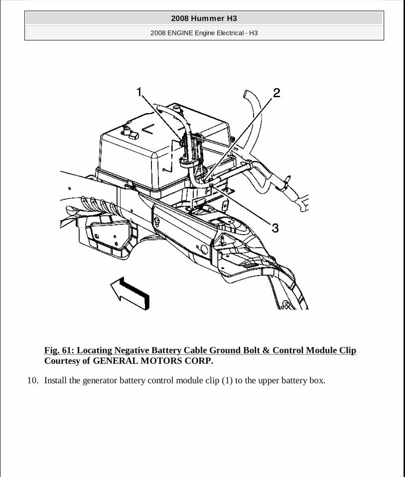
Fig. 61: Locating Negative Battery Cable Ground Bolt & Control Module Clip Courtesy of GENERAL MOTORS CORP.
10. Install the generator battery control module clip (1) to the upper battery box.
2008 Hummer H3
2008 ENGINE Engine Electrical - H3
MY
Sunday, March 29, 2009 10:52:08 PM Page 124 © 2005 Mitchell Repair Information Company, LLC.
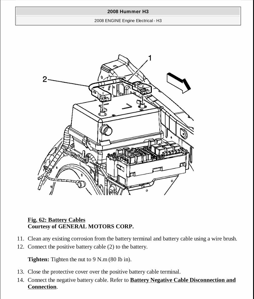
Fig. 62: Battery Cables Courtesy of GENERAL MOTORS CORP.
11. Clean any existing corrosion from the battery terminal and battery cable using a wire brush. 12. Connect the positive battery cable (2) to the battery.
Tighten: Tighten the nut to 9 N.m (80 lb in).
13. Close the protective cover over the positive battery cable terminal.
14. Connect the negative battery cable. Refer to Battery Negative Cable Disconnection and Connection.
2008 Hummer H3
2008 ENGINE Engine Electrical - H3
MY
Sunday, March 29, 2009 10:52:08 PM Page 125 © 2005 Mitchell Repair Information Company, LLC.
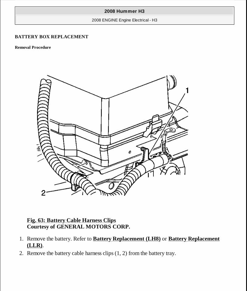
BATTERY BOX REPLACEMENT
Removal Procedure
Fig. 63: Battery Cable Harness Clips Courtesy of GENERAL MOTORS CORP.
1. Remove the battery. Refer to Battery Replacement (LH8) or Battery Replacement (LLR) .
2. Remove the battery cable harness clips (1, 2) from the battery tray.
2008 Hummer H3
2008 ENGINE Engine Electrical - H3
MY
Sunday, March 29, 2009 10:52:08 PM Page 126 © 2005 Mitchell Repair Information Company, LLC.
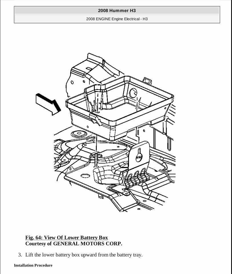
Fig. 64: View Of Lower Battery Box Courtesy of GENERAL MOTORS CORP.
3. Lift the lower battery box upward from the battery tray.
Installation Procedure
2008 Hummer H3
2008 ENGINE Engine Electrical - H3
MY
Sunday, March 29, 2009 10:52:08 PM Page 127 © 2005 Mitchell Repair Information Company, LLC.
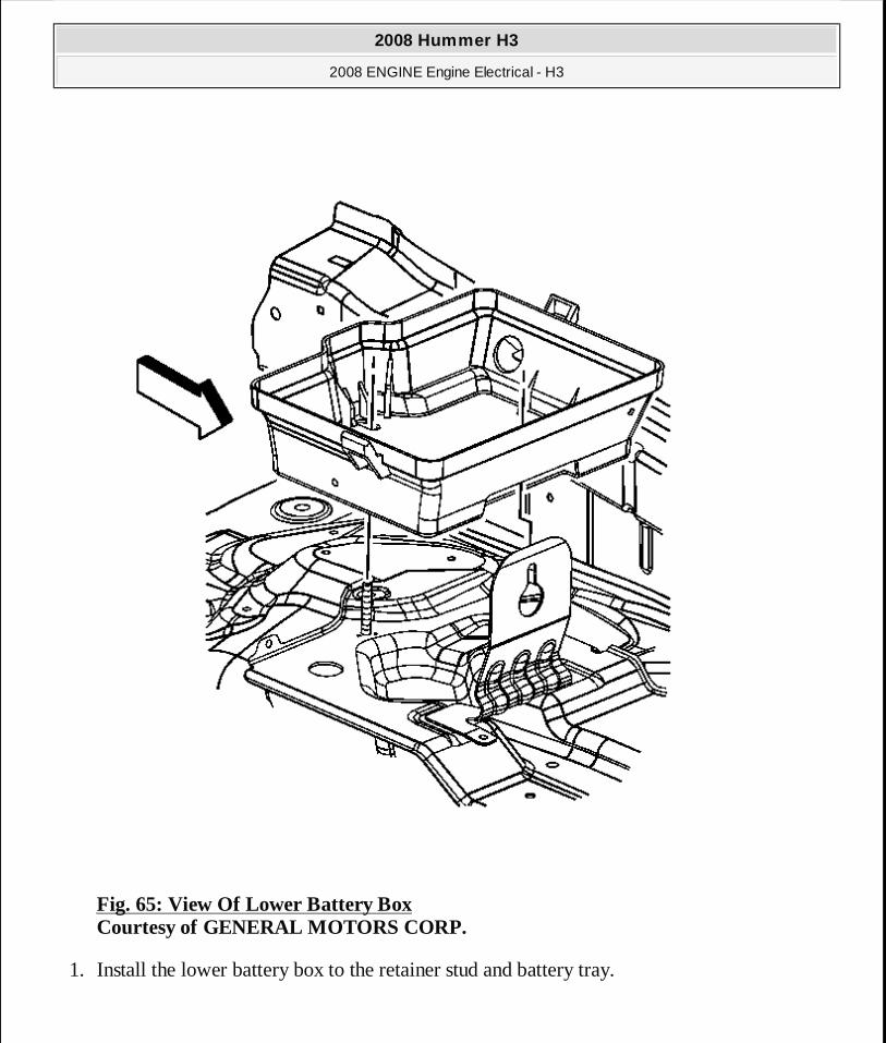
Fig. 65: View Of Lower Battery Box Courtesy of GENERAL MOTORS CORP.
1. Install the lower battery box to the retainer stud and battery tray.
2008 Hummer H3
2008 ENGINE Engine Electrical - H3
MY
Sunday, March 29, 2009 10:52:08 PM Page 128 © 2005 Mitchell Repair Information Company, LLC.
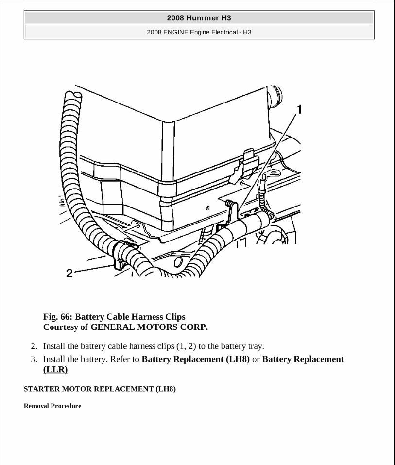
Fig. 66: Battery Cable Harness Clips Courtesy of GENERAL MOTORS CORP.
2. Install the battery cable harness clips (1, 2) to the battery tray.
3. Install the battery. Refer to Battery Replacement (LH8) or Battery Replacement (LLR) .
STARTER MOTOR REPLACEMENT (LH8)
Removal Procedure
2008 Hummer H3
2008 ENGINE Engine Electrical - H3
MY
Sunday, March 29, 2009 10:52:08 PM Page 129 © 2005 Mitchell Repair Information Company, LLC.
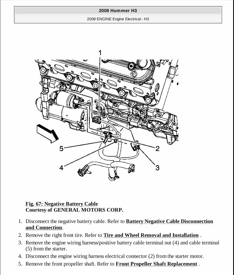
Fig. 67: Negative Battery Cable Courtesy of GENERAL MOTORS CORP.
1. Disconnect the negative battery cable. Refer to Battery Negative Cable Disconnection and Connection.
2. Remove the right front tire. Refer to Tire and Wheel Removal and Installation . 3. Remove the engine wiring harness/positive battery cable terminal nut (4) and cable terminal
(5) from the starter. 4. Disconnect the engine wiring harness electrical connector (2) from the starter motor.
5. Remove the front propeller shaft. Refer to Front Propeller Shaft Replacement .
2008 Hummer H3
2008 ENGINE Engine Electrical - H3
MY
Sunday, March 29, 2009 10:52:08 PM Page 130 © 2005 Mitchell Repair Information Company, LLC.
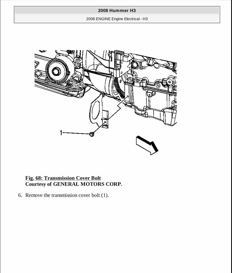
Fig. 68: Transmission Cover Bolt Courtesy of GENERAL MOTORS CORP.
6. Remove the transmission cover bolt (1).
2008 Hummer H3
2008 ENGINE Engine Electrical - H3
MY
Sunday, March 29, 2009 10:52:08 PM Page 131 © 2005 Mitchell Repair Information Company, LLC.
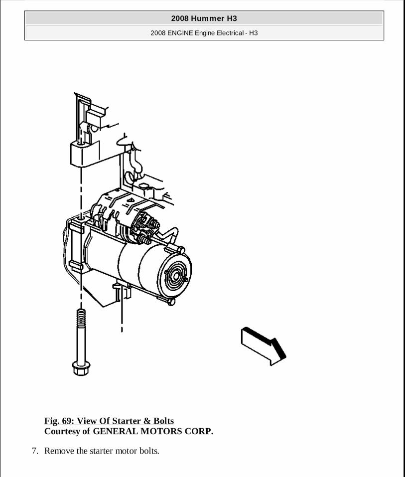
Fig. 69: View Of Starter & Bolts Courtesy of GENERAL MOTORS CORP.
7. Remove the starter motor bolts.
2008 Hummer H3
2008 ENGINE Engine Electrical - H3
MY
Sunday, March 29, 2009 10:52:08 PM Page 132 © 2005 Mitchell Repair Information Company, LLC.

Fig. 70: View Of Transmission Cover & Starter Courtesy of GENERAL MOTORS CORP.
8. Unsnap the transmission cover from the starter.
2008 Hummer H3
2008 ENGINE Engine Electrical - H3
MY
Sunday, March 29, 2009 10:52:08 PM Page 133 © 2005 Mitchell Repair Information Company, LLC.
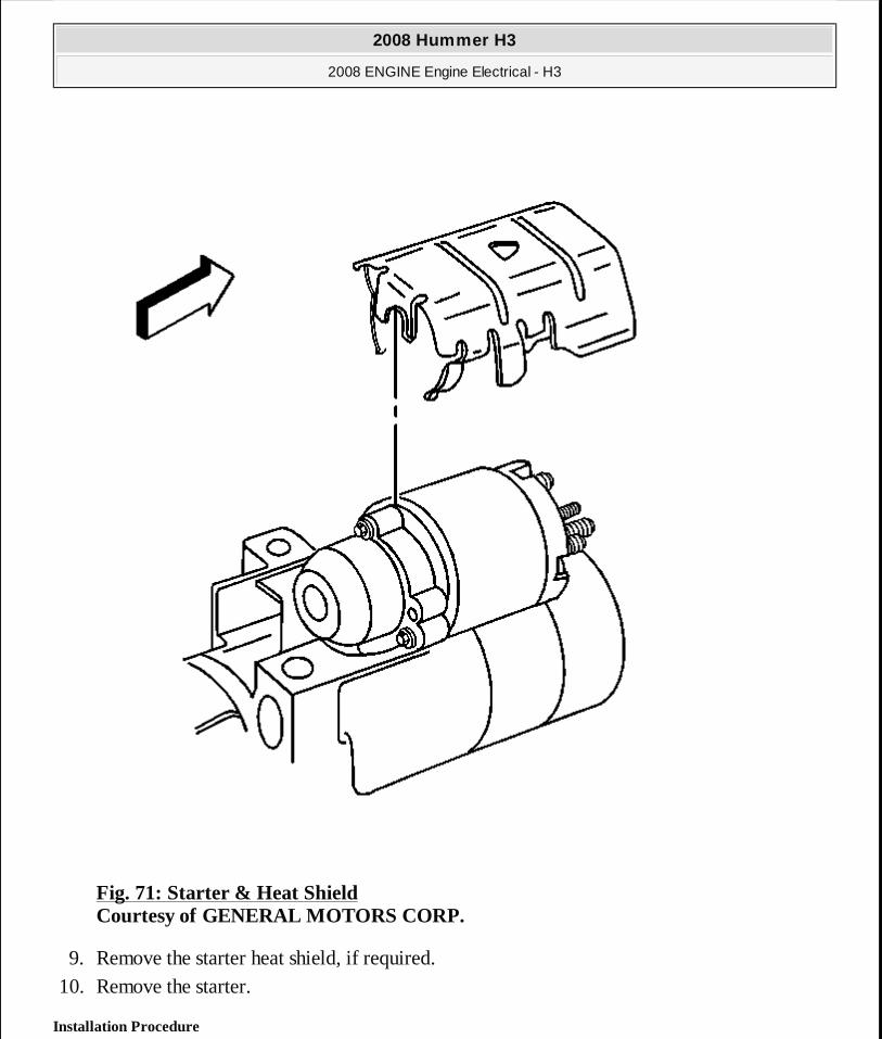
Fig. 71: Starter & Heat Shield Courtesy of GENERAL MOTORS CORP.
9. Remove the starter heat shield, if required. 10. Remove the starter.
Installation Procedure
2008 Hummer H3
2008 ENGINE Engine Electrical - H3
MY
Sunday, March 29, 2009 10:52:08 PM Page 134 © 2005 Mitchell Repair Information Company, LLC.
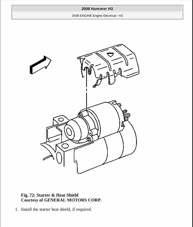
Fig. 72: Starter & Heat Shield Courtesy of GENERAL MOTORS CORP.
1. Install the starter heat shield, if required.
2008 Hummer H3
2008 ENGINE Engine Electrical - H3
MY
Sunday, March 29, 2009 10:52:08 PM Page 135 © 2005 Mitchell Repair Information Company, LLC.
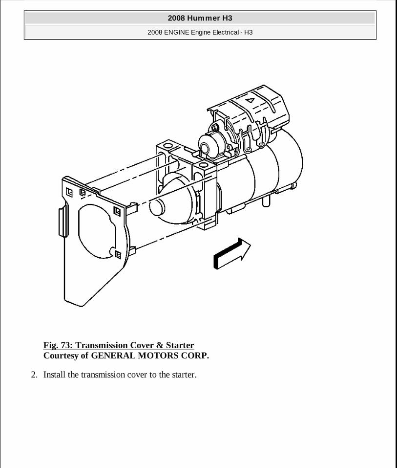
Fig. 73: Transmission Cover & Starter Courtesy of GENERAL MOTORS CORP.
2. Install the transmission cover to the starter.
2008 Hummer H3
2008 ENGINE Engine Electrical - H3
MY
Sunday, March 29, 2009 10:52:08 PM Page 136 © 2005 Mitchell Repair Information Company, LLC.
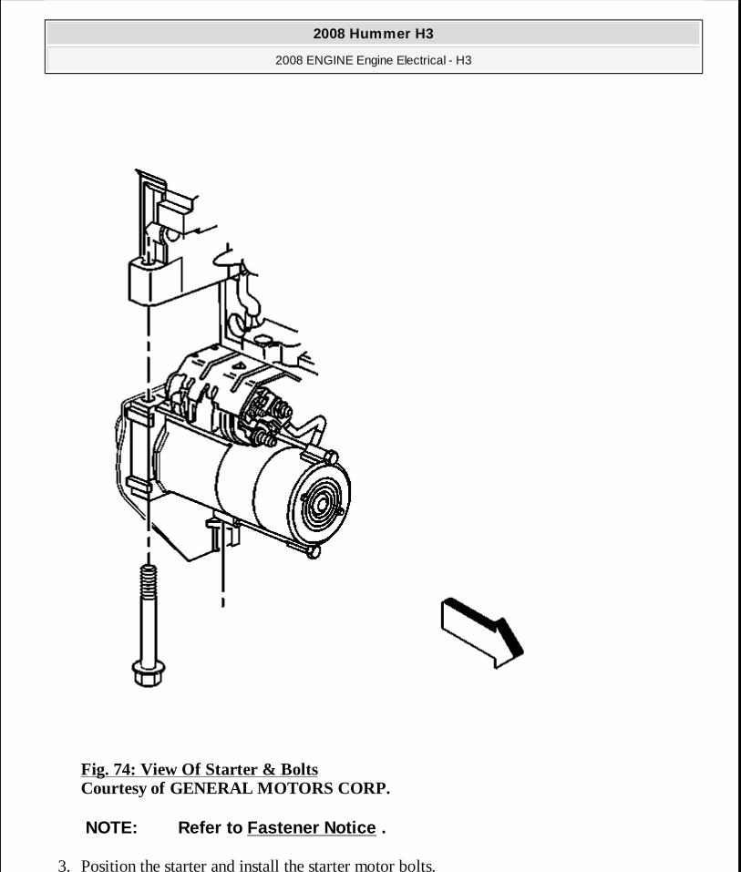
Fig. 74: View Of Starter & Bolts Courtesy of GENERAL MOTORS CORP.
3. Position the starter and install the starter motor bolts.
NOTE: Refer to Fastener Notice .
2008 Hummer H3
2008 ENGINE Engine Electrical - H3
MY
Sunday, March 29, 2009 10:52:08 PM Page 137 © 2005 Mitchell Repair Information Company, LLC.
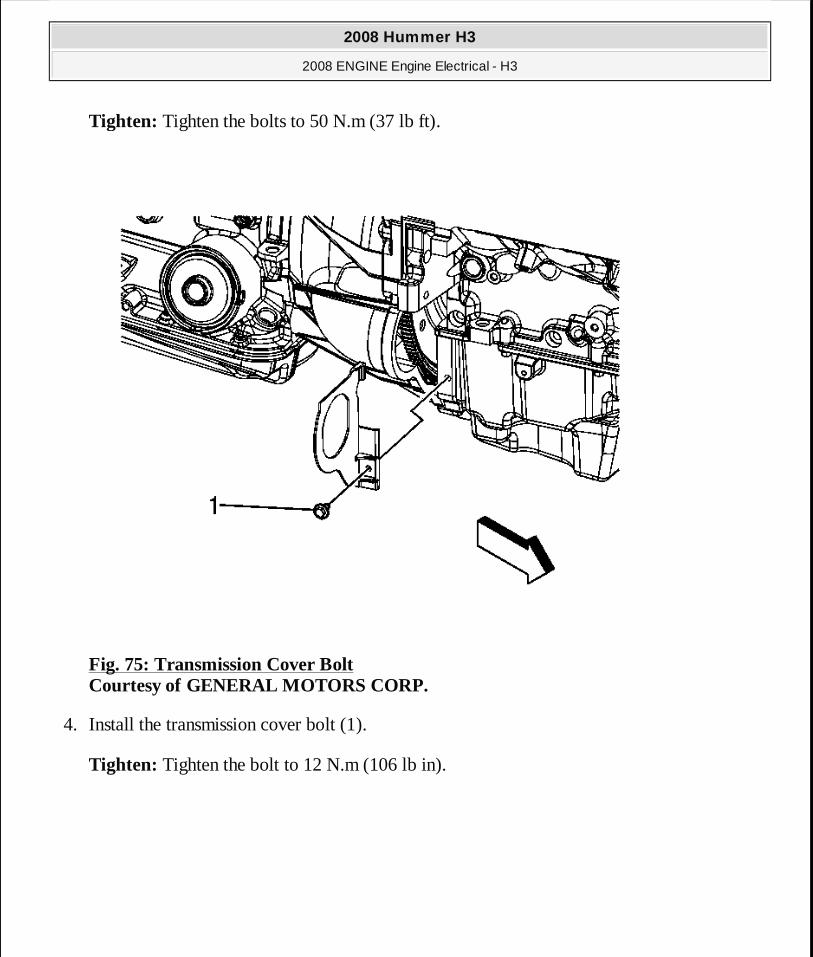
Tighten: Tighten the bolts to 50 N.m (37 lb ft).
Fig. 75: Transmission Cover Bolt Courtesy of GENERAL MOTORS CORP.
4. Install the transmission cover bolt (1).
Tighten: Tighten the bolt to 12 N.m (106 lb in).
2008 Hummer H3
2008 ENGINE Engine Electrical - H3
MY
Sunday, March 29, 2009 10:52:08 PM Page 138 © 2005 Mitchell Repair Information Company, LLC.
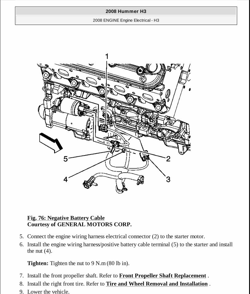
Fig. 76: Negative Battery Cable Courtesy of GENERAL MOTORS CORP.
5. Connect the engine wiring harness electrical connector (2) to the starter motor. 6. Install the engine wiring harness/positive battery cable terminal (5) to the starter and install
the nut (4).
Tighten: Tighten the nut to 9 N.m (80 lb in).
7. Install the front propeller shaft. Refer to Front Propeller Shaft Replacement . 8. Install the right front tire. Refer to Tire and Wheel Removal and Installation . 9. Lower the vehicle.
2008 Hummer H3
2008 ENGINE Engine Electrical - H3
MY
Sunday, March 29, 2009 10:52:08 PM Page 139 © 2005 Mitchell Repair Information Company, LLC.
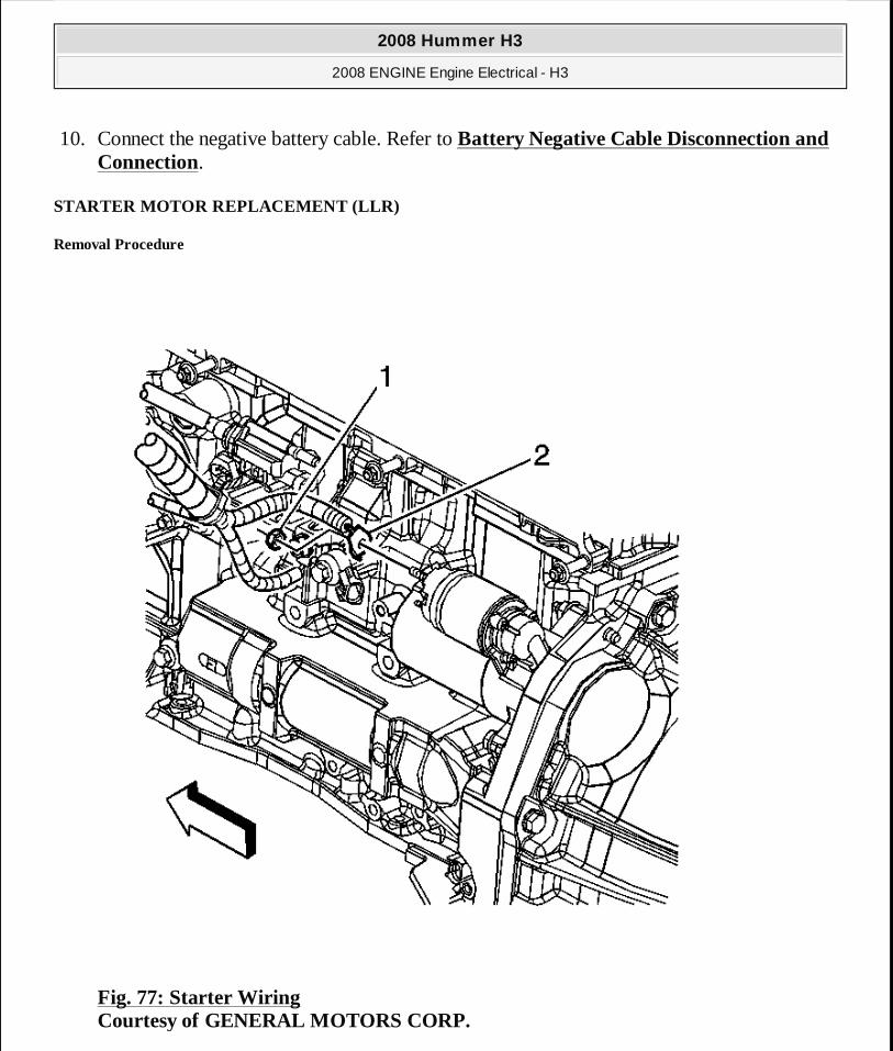
10. Connect the negative battery cable. Refer to Battery Negative Cable Disconnection and Connection.
STARTER MOTOR REPLACEMENT (LLR)
Removal Procedure
Fig. 77: Starter Wiring Courtesy of GENERAL MOTORS CORP.
2008 Hummer H3
2008 ENGINE Engine Electrical - H3
MY
Sunday, March 29, 2009 10:52:08 PM Page 140 © 2005 Mitchell Repair Information Company, LLC.
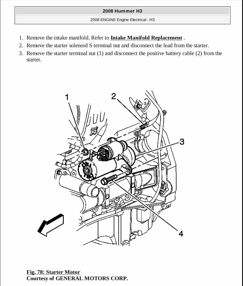
1. Remove the intake manifold. Refer to Intake Manifold Replacement . 2. Remove the starter solenoid S terminal nut and disconnect the lead from the starter. 3. Remove the starter terminal nut (1) and disconnect the positive battery cable (2) from the
starter.
Fig. 78: Starter Motor Courtesy of GENERAL MOTORS CORP.
2008 Hummer H3
2008 ENGINE Engine Electrical - H3
MY
Sunday, March 29, 2009 10:52:08 PM Page 141 © 2005 Mitchell Repair Information Company, LLC.
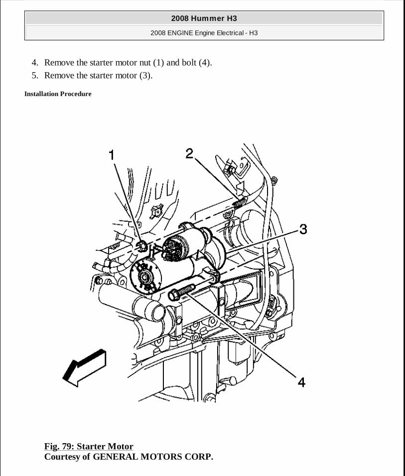
4. Remove the starter motor nut (1) and bolt (4). 5. Remove the starter motor (3).
Installation Procedure
Fig. 79: Starter Motor Courtesy of GENERAL MOTORS CORP.
2008 Hummer H3
2008 ENGINE Engine Electrical - H3
MY
Sunday, March 29, 2009 10:52:08 PM Page 142 © 2005 Mitchell Repair Information Company, LLC.
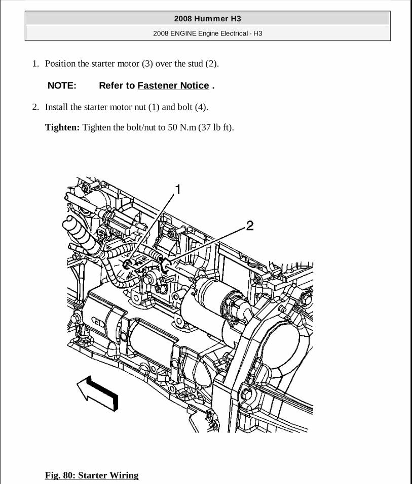
1. Position the starter motor (3) over the stud (2).
2. Install the starter motor nut (1) and bolt (4).
Tighten: Tighten the bolt/nut to 50 N.m (37 lb ft).
Fig. 80: Starter Wiring
NOTE: Refer to Fastener Notice .
2008 Hummer H3
2008 ENGINE Engine Electrical - H3
MY
Sunday, March 29, 2009 10:52:08 PM Page 143 © 2005 Mitchell Repair Information Company, LLC.
Courtesy of GENERAL MOTORS CORP.
3. Connect the battery positive cable (2) to the starter and install the starter terminal nut (1).
Tighten: Tighten the nut to 9 N.m (80 lb in).
4. Connect the lead to the starter solenoid and install the starter solenoid S terminal nut.
Tighten: Tighten the nut to 3.5 N.m (31 lb in).
5. Install the intake manifold. Refer to Intake Manifold Replacement .
GENERATOR BRACKET REPLACEMENT
Removal Procedure
2008 Hummer H3
2008 ENGINE Engine Electrical - H3
MY
Sunday, March 29, 2009 10:52:08 PM Page 144 © 2005 Mitchell Repair Information Company, LLC.
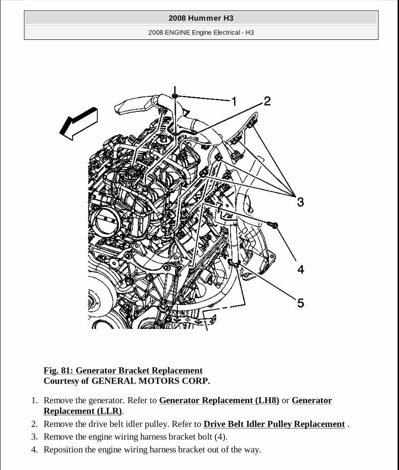
Fig. 81: Generator Bracket Replacement Courtesy of GENERAL MOTORS CORP.
1. Remove the generator. Refer to Generator Replacement (LH8) or Generator Replacement (LLR).
2. Remove the drive belt idler pulley. Refer to Drive Belt Idler Pulley Replacement . 3. Remove the engine wiring harness bracket bolt (4). 4. Reposition the engine wiring harness bracket out of the way.
2008 Hummer H3
2008 ENGINE Engine Electrical - H3
MY
Sunday, March 29, 2009 10:52:08 PM Page 145 © 2005 Mitchell Repair Information Company, LLC.
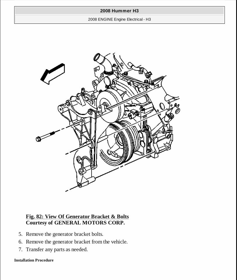
Fig. 82: View Of Generator Bracket & Bolts Courtesy of GENERAL MOTORS CORP.
5. Remove the generator bracket bolts. 6. Remove the generator bracket from the vehicle. 7. Transfer any parts as needed.
Installation Procedure
2008 Hummer H3
2008 ENGINE Engine Electrical - H3
MY
Sunday, March 29, 2009 10:52:08 PM Page 146 © 2005 Mitchell Repair Information Company, LLC.
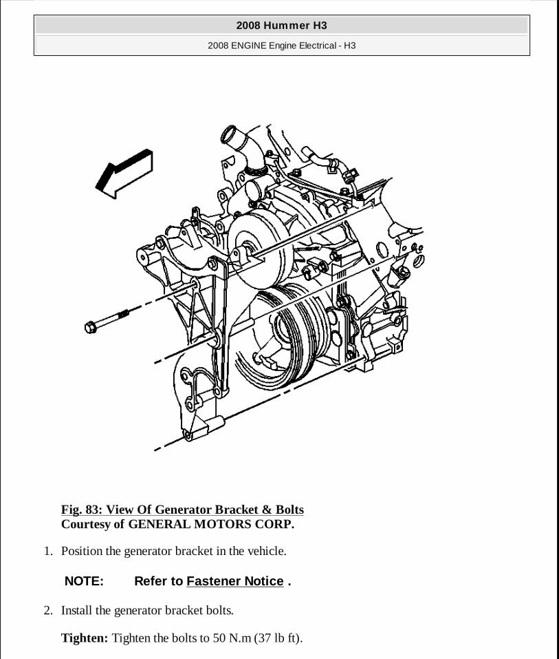
Fig. 83: View Of Generator Bracket & Bolts Courtesy of GENERAL MOTORS CORP.
1. Position the generator bracket in the vehicle.
2. Install the generator bracket bolts.
Tighten: Tighten the bolts to 50 N.m (37 lb ft).
NOTE: Refer to Fastener Notice .
2008 Hummer H3
2008 ENGINE Engine Electrical - H3
MY
Sunday, March 29, 2009 10:52:08 PM Page 147 © 2005 Mitchell Repair Information Company, LLC.
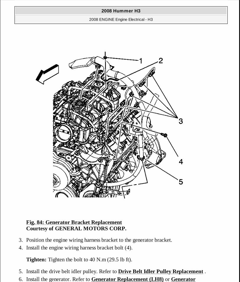
Fig. 84: Generator Bracket Replacement Courtesy of GENERAL MOTORS CORP.
3. Position the engine wiring harness bracket to the generator bracket. 4. Install the engine wiring harness bracket bolt (4).
Tighten: Tighten the bolt to 40 N.m (29.5 lb ft).
5. Install the drive belt idler pulley. Refer to Drive Belt Idler Pulley Replacement . 6. Install the generator. Refer to Generator Replacement (LH8) or Generator
2008 Hummer H3
2008 ENGINE Engine Electrical - H3
MY
Sunday, March 29, 2009 10:52:09 PM Page 148 © 2005 Mitchell Repair Information Company, LLC.
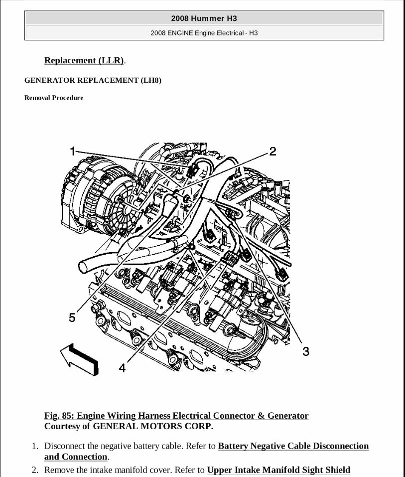
Replacement (LLR).
GENERATOR REPLACEMENT (LH8)
Removal Procedure
Fig. 85: Engine Wiring Harness Electrical Connector & Generator Courtesy of GENERAL MOTORS CORP.
1. Disconnect the negative battery cable. Refer to Battery Negative Cable Disconnection and Connection.
2. Remove the intake manifold cover. Refer to Upper Intake Manifold Sight Shield
2008 Hummer H3
2008 ENGINE Engine Electrical - H3
MY
Sunday, March 29, 2009 10:52:09 PM Page 149 © 2005 Mitchell Repair Information Company, LLC.
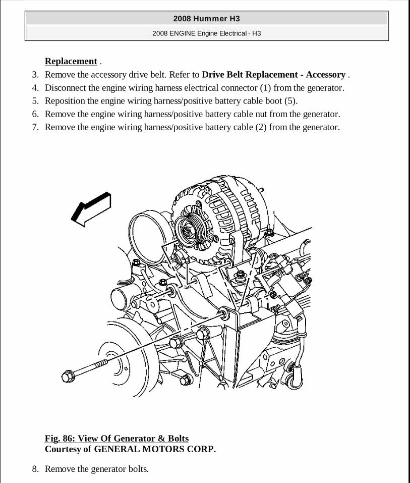
Replacement . 3. Remove the accessory drive belt. Refer to Drive Belt Replacement - Accessory . 4. Disconnect the engine wiring harness electrical connector (1) from the generator. 5. Reposition the engine wiring harness/positive battery cable boot (5). 6. Remove the engine wiring harness/positive battery cable nut from the generator. 7. Remove the engine wiring harness/positive battery cable (2) from the generator.
Fig. 86: View Of Generator & Bolts Courtesy of GENERAL MOTORS CORP.
8. Remove the generator bolts.
2008 Hummer H3
2008 ENGINE Engine Electrical - H3
MY
Sunday, March 29, 2009 10:52:09 PM Page 150 © 2005 Mitchell Repair Information Company, LLC.
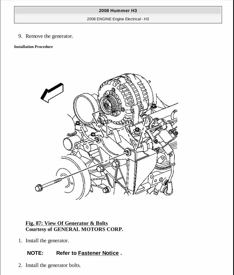
9. Remove the generator.
Installation Procedure
Fig. 87: View Of Generator & Bolts Courtesy of GENERAL MOTORS CORP.
1. Install the generator.
2. Install the generator bolts.
NOTE: Refer to Fastener Notice .
2008 Hummer H3
2008 ENGINE Engine Electrical - H3
MY
Sunday, March 29, 2009 10:52:09 PM Page 151 © 2005 Mitchell Repair Information Company, LLC.
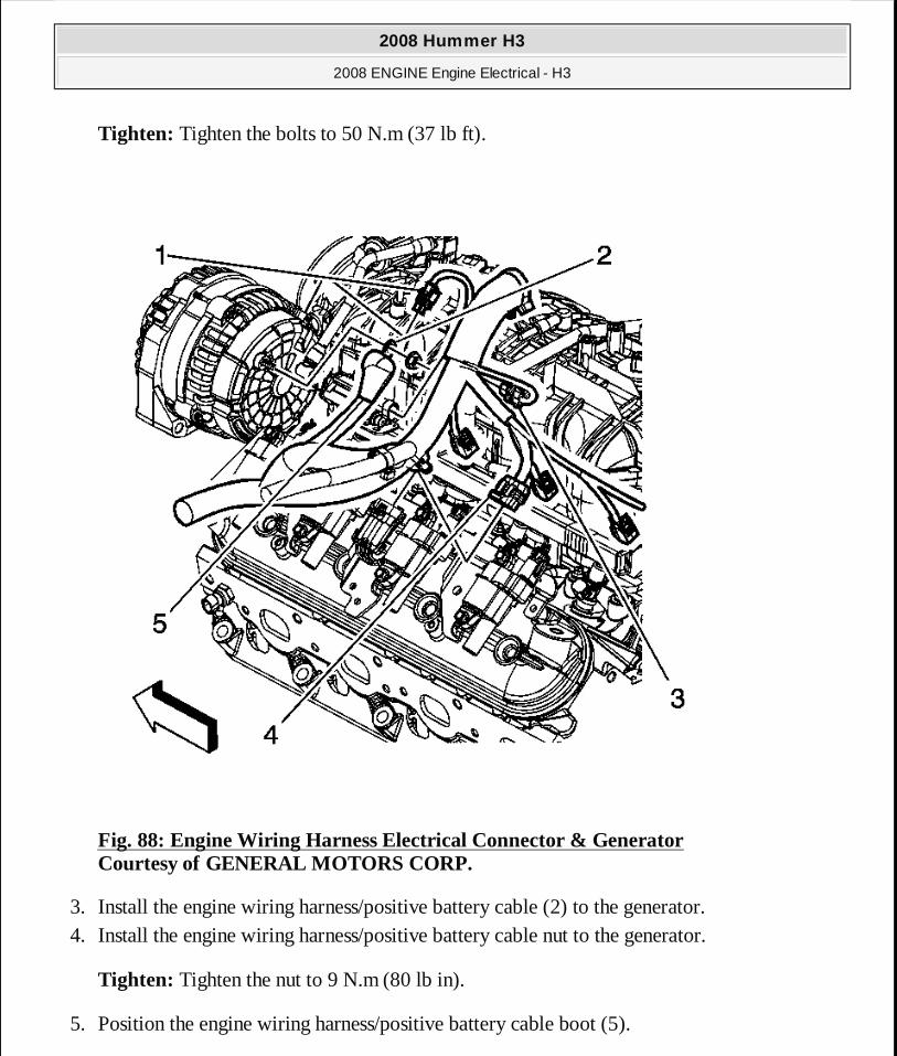
Tighten: Tighten the bolts to 50 N.m (37 lb ft).
Fig. 88: Engine Wiring Harness Electrical Connector & Generator Courtesy of GENERAL MOTORS CORP.
3. Install the engine wiring harness/positive battery cable (2) to the generator. 4. Install the engine wiring harness/positive battery cable nut to the generator.
Tighten: Tighten the nut to 9 N.m (80 lb in).
5. Position the engine wiring harness/positive battery cable boot (5).
2008 Hummer H3
2008 ENGINE Engine Electrical - H3
MY
Sunday, March 29, 2009 10:52:09 PM Page 152 © 2005 Mitchell Repair Information Company, LLC.

6. Connect the engine wiring harness electrical connector (1) to the generator.
7. Install the accessory drive belt. Refer to Drive Belt Replacement - Accessory . 8. Install the intake manifold cover. Refer to Upper Intake Manifold Sight Shield
Replacement . 9. Connect the negative battery cable. Refer to Battery Negative Cable Disconnection and
Connection.
GENERATOR REPLACEMENT (LLR)
Removal Procedure
Fig. 89: View Of A/C Compressor Courtesy of GENERAL MOTORS CORP.
2008 Hummer H3
2008 ENGINE Engine Electrical - H3
MY
Sunday, March 29, 2009 10:52:09 PM Page 153 © 2005 Mitchell Repair Information Company, LLC.
1. Disconnect the negative battery cable. Refer to Battery Negative Cable Disconnection and Connection.
2. Remove the drive belt. Refer to Drive Belt Replacement (Without A/C) or Drive Belt Replacement (With A/C) .
3. Raise and support the vehicle only high enough to access the air conditioning (A/C) compressor through the wheelhouse. Refer to Lifting and Jacking the Vehicle .
4. Remove the left front wheel. Refer to Tire and Wheel Removal and Installation . 5. Remove the left wheelhouse liner. Refer to Wheelhouse Panel Replacement (Front) or
Wheelhouse Panel Replacement (Rear) . 6. Disengage the A/C compressor electrical connector from the bracket.
7. Recover the A/C system. Refer to Refrigerant Recovery and Recharging (Non HP2) . 8. Disconnect the A/C condenser and evaporator lines from the compressor. 9. Remove the A/C compressor mounting bolts (2, 3) ONLY.
The upper mounting bolt (2) will remain with the A/C compressor (1).
10. Lower the vehicle.
2008 Hummer H3
2008 ENGINE Engine Electrical - H3
MY
Sunday, March 29, 2009 10:52:09 PM Page 154 © 2005 Mitchell Repair Information Company, LLC.
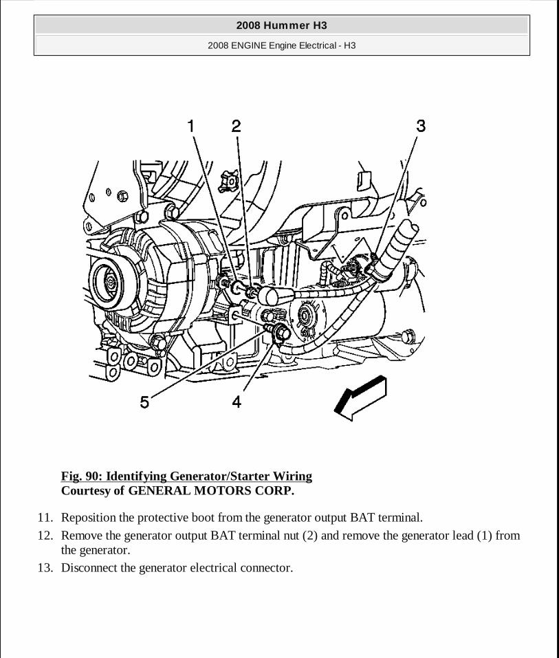
Fig. 90: Identifying Generator/Starter Wiring Courtesy of GENERAL MOTORS CORP.
11. Reposition the protective boot from the generator output BAT terminal. 12. Remove the generator output BAT terminal nut (2) and remove the generator lead (1) from
the generator. 13. Disconnect the generator electrical connector.
2008 Hummer H3
2008 ENGINE Engine Electrical - H3
MY
Sunday, March 29, 2009 10:52:09 PM Page 155 © 2005 Mitchell Repair Information Company, LLC.
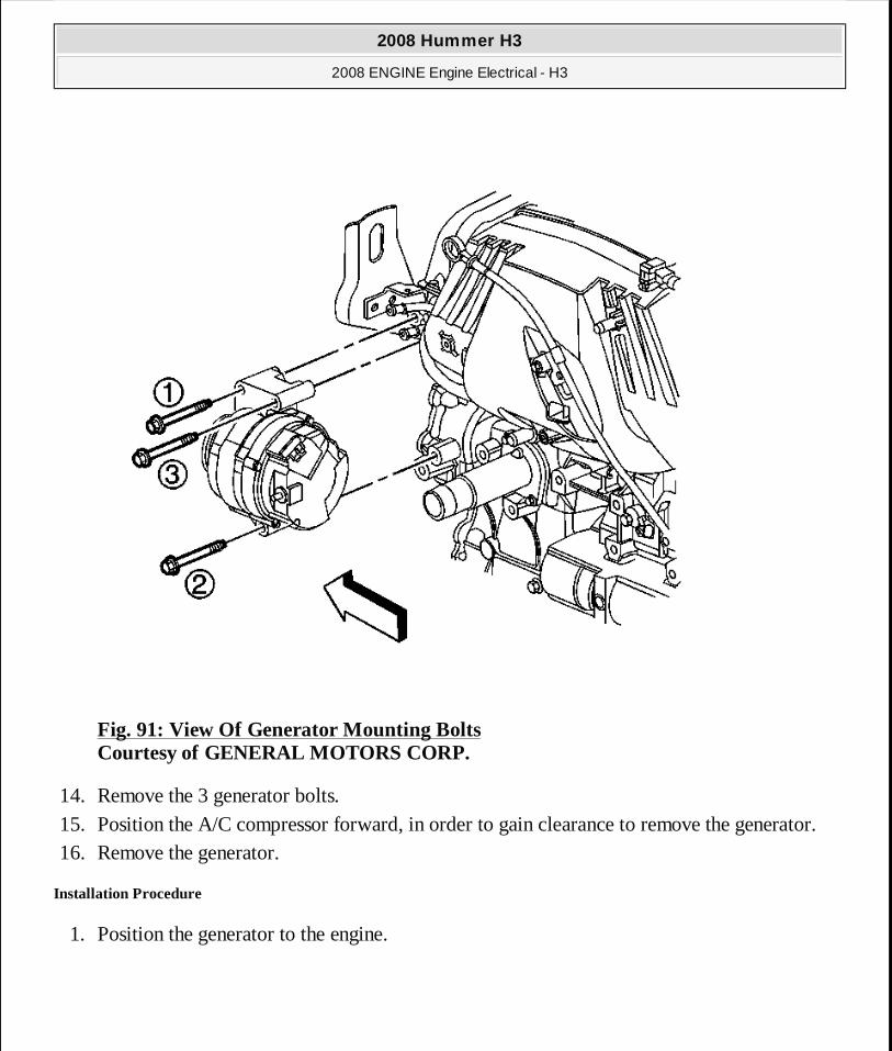
Fig. 91: View Of Generator Mounting Bolts Courtesy of GENERAL MOTORS CORP.
14. Remove the 3 generator bolts. 15. Position the A/C compressor forward, in order to gain clearance to remove the generator. 16. Remove the generator.
Installation Procedure
1. Position the generator to the engine.
2008 Hummer H3
2008 ENGINE Engine Electrical - H3
MY
Sunday, March 29, 2009 10:52:09 PM Page 156 © 2005 Mitchell Repair Information Company, LLC.
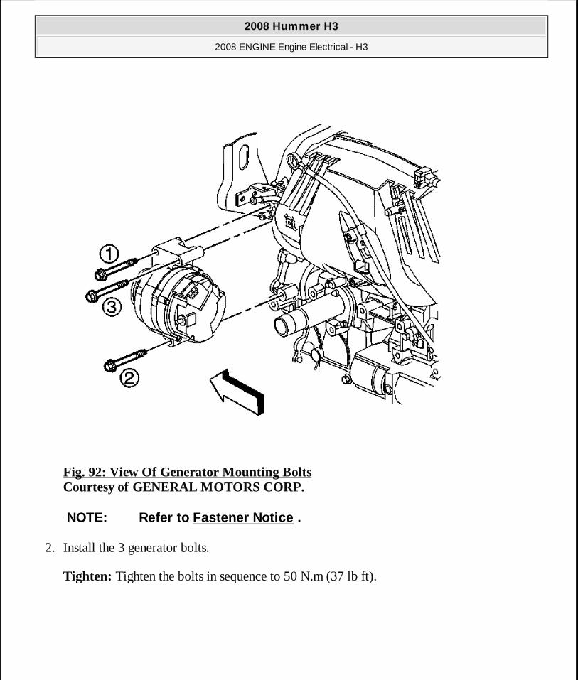
Fig. 92: View Of Generator Mounting Bolts Courtesy of GENERAL MOTORS CORP.
2. Install the 3 generator bolts.
Tighten: Tighten the bolts in sequence to 50 N.m (37 lb ft).
NOTE: Refer to Fastener Notice .
2008 Hummer H3
2008 ENGINE Engine Electrical - H3
MY
Sunday, March 29, 2009 10:52:09 PM Page 157 © 2005 Mitchell Repair Information Company, LLC.
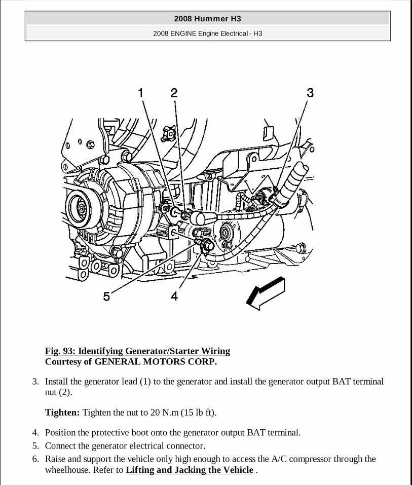
Fig. 93: Identifying Generator/Starter Wiring Courtesy of GENERAL MOTORS CORP.
3. Install the generator lead (1) to the generator and install the generator output BAT terminal nut (2).
Tighten: Tighten the nut to 20 N.m (15 lb ft).
4. Position the protective boot onto the generator output BAT terminal. 5. Connect the generator electrical connector. 6. Raise and support the vehicle only high enough to access the A/C compressor through the
wheelhouse. Refer to Lifting and Jacking the Vehicle .
2008 Hummer H3
2008 ENGINE Engine Electrical - H3
MY
Sunday, March 29, 2009 10:52:09 PM Page 158 © 2005 Mitchell Repair Information Company, LLC.
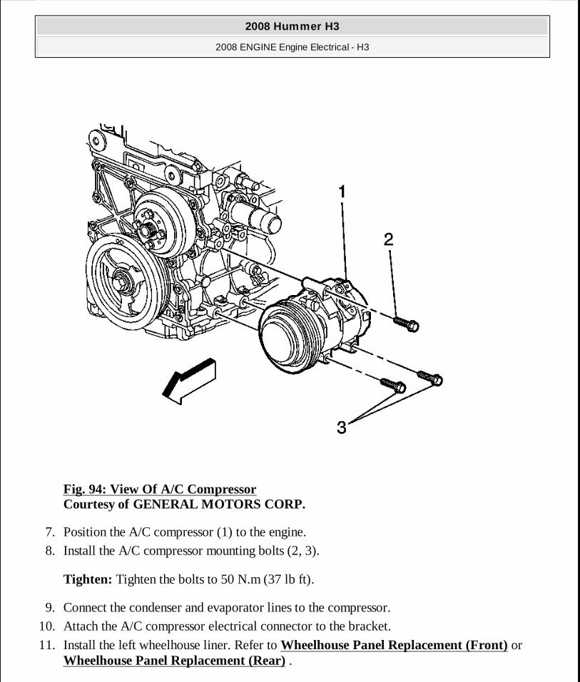
Fig. 94: View Of A/C Compressor Courtesy of GENERAL MOTORS CORP.
7. Position the A/C compressor (1) to the engine. 8. Install the A/C compressor mounting bolts (2, 3).
Tighten: Tighten the bolts to 50 N.m (37 lb ft).
9. Connect the condenser and evaporator lines to the compressor. 10. Attach the A/C compressor electrical connector to the bracket.
11. Install the left wheelhouse liner. Refer to Wheelhouse Panel Replacement (Front) or Wheelhouse Panel Replacement (Rear) .
2008 Hummer H3
2008 ENGINE Engine Electrical - H3
MY
Sunday, March 29, 2009 10:52:09 PM Page 159 © 2005 Mitchell Repair Information Company, LLC.
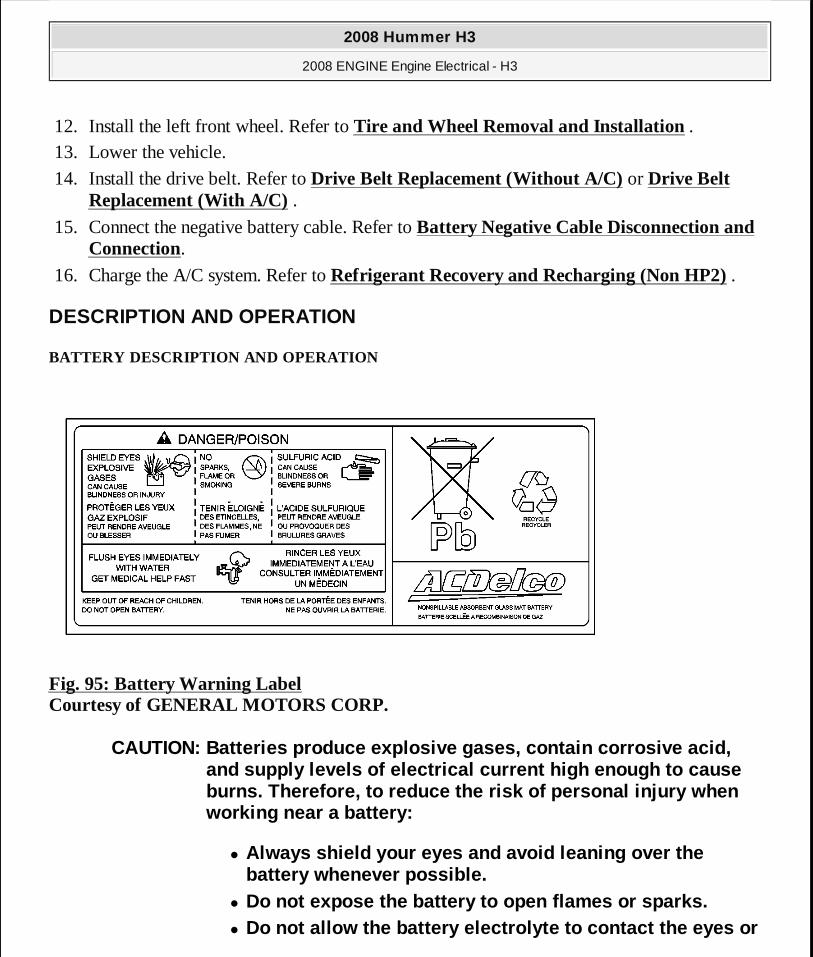
12. Install the left front wheel. Refer to Tire and Wheel Removal and Installation . 13. Lower the vehicle.
14. Install the drive belt. Refer to Drive Belt Replacement (Without A/C) or Drive Belt Replacement (With A/C) .
15. Connect the negative battery cable. Refer to Battery Negative Cable Disconnection and Connection.
16. Charge the A/C system. Refer to Refrigerant Recovery and Recharging (Non HP2) .
DESCRIPTION AND OPERATION
BATTERY DESCRIPTION AND OPERATION
Fig. 95: Battery Warning Label Courtesy of GENERAL MOTORS CORP.
CAUTION: Batteries produce explosive gases, contain corrosive acid, and supply levels of electrical current high enough to cause burns. Therefore, to reduce the risk of personal in jury when working near a battery:
� Always shield your eyes and avoid leaning over the battery whenever possible.
� Do not expose the battery to open flames or sparks. � Do not allow the battery electrolyte to contact the eyes or
2008 Hummer H3
2008 ENGINE Engine Electrical - H3
MY
Sunday, March 29, 2009 10:52:09 PM Page 160 © 2005 Mitchell Repair Information Company, LLC.
Batteries that are no longer wanted must be disposed of by an approved battery recycler and must never be thrown in the trash or sent to a landfill.
Batteries that are not part of the vehicle itself, not the battery under the hood, must only be transported on public streets for business purposes via approved hazardous material transportation procedures.
Battery storage, charging, and testing facilities in repair shops must meet various requirements for ventilation, safety equipment, material segregation, etc.
The maintenance-free battery is standard. There are no vent plugs in the cover. The battery is completely sealed except for 2 small vent holes in the side. These vent holes allow the small amount of gas that is produced in the battery to escape.
The battery has 3 functions as a major source of energy:
� Engine cranking � Voltage stabilizer � Alternate source of energy with generator overload
The battery specification label, example below, contains information about the following:
� The test ratings � The original equipment catalog number � The recommended replacement model number
the skin. Flush immediately and thoroughly any cont acted areas with water and get medical help.
� Follow each step of the jump starting procedure in order. � Treat both the booster and the discharged batteries
carefully when using the jumper cables.
IMPORTANT: Because of the materials used in the manu facture of automotive lead-acid batteries, dealers and service shops that handle them are subject to various regulations issued by OSHA, EPA, DOT, and various state or local agencies. Other regulati ons may also apply in other locations. Always know and follow th ese regulations when handling batteries.
2008 Hummer H3
2008 ENGINE Engine Electrical - H3
MY
Sunday, March 29, 2009 10:52:09 PM Page 161 © 2005 Mitchell Repair Information Company, LLC.
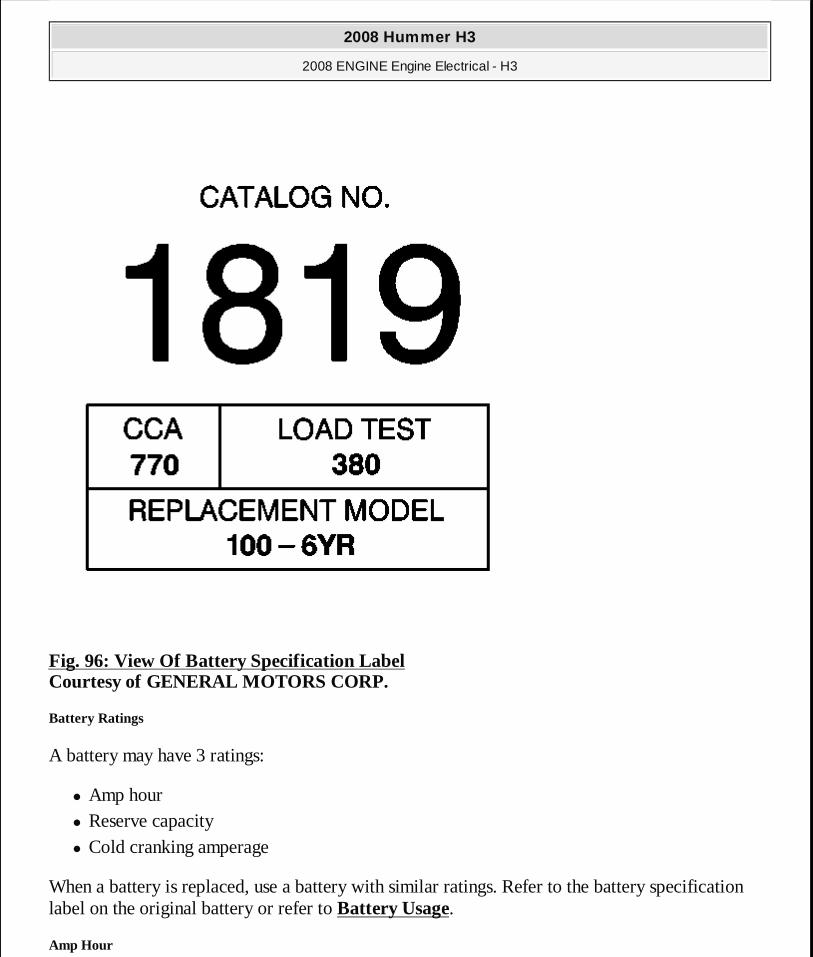
Fig. 96: View Of Battery Specification Label Courtesy of GENERAL MOTORS CORP.
Battery Ratings
A battery may have 3 ratings:
� Amp hour � Reserve capacity � Cold cranking amperage
When a battery is replaced, use a battery with similar ratings. Refer to the battery specification label on the original battery or refer to Battery Usage.
Amp Hour
2008 Hummer H3
2008 ENGINE Engine Electrical - H3
MY
Sunday, March 29, 2009 10:52:09 PM Page 162 © 2005 Mitchell Repair Information Company, LLC.
The amp hour rating of a battery is the amount of time it takes a fully charged battery, being discharged at a constant rate of 1 amperes and a constant temperature of 27°C (80°F), to reach a terminal voltage of 10.5 volts. Refer to Battery Usage for the amp hour rating of the original equipment battery.
Reserve Capacity
Reserve capacity is the amount of time in minutes it takes a fully charged battery, being discharged at a constant rate of 25 amperes and a constant temperature of 27°C (80°F), to reach a terminal voltage of 10.5 volts. Refer to Battery Usage for the reserve capacity rating of the original equipment battery.
Cold Cranking Amperage
The cold cranking amperage is an indication of the ability of the battery to crank the engine at cold temperatures. The cold cranking amperage rating is the minimum amperage the battery must maintain for 30 seconds at -18°C (0°F) while maintaining at least 7.2 volts. Refer to Battery Usage for the cold cranking amperage rating for this vehicle.
CHARGING SYSTEM DESCRIPTION AND OPERATION
Electrical Power Management (EPM) Overview
The Electrical Power Management (EPM) System is designed to monitor and control the charging system and send diagnostic messages to alert the driver of possible problems with the battery and generator. This EPM System primarily utilizes existing on-board computer capability to maximize the effectiveness of the generator, to manage the load, improve battery state-of-charge (SOC) and life, and minimize the systems impact on fuel economy. The EPM System performs 3 functions:
� It monitors the battery voltage and estimates the battery condition. � It takes corrective actions by adjusting the regulated voltage. � It performs diagnostics and driver notification.
The battery condition is estimated during key-off and during key-on. During key-off the SOC of the battery is determined by measuring the open-circuit voltage. The SOC is a function of the acid concentration and the internal resistance of the battery, and is estimated by reading the battery open-circuit-voltage when the battery has been at rest for several hours.
The SOC can be used as a diagnostic tool to tell the customer or the dealer the condition of the battery. Throughout key-on the algorithm continuously estimates SOC based on adjusted net amp
2008 Hummer H3
2008 ENGINE Engine Electrical - H3
MY
Sunday, March 29, 2009 10:52:09 PM Page 163 © 2005 Mitchell Repair Information Company, LLC.
hours, battery capacity, initial SOC, and temperature.
While running, the battery degree of discharge is primarily determined by a battery current sensor, which is integrated to obtain net amp hours.
In addition, the EPM function is designed to perform regulated voltage control (RVC) to improve battery SOC, battery life, and fuel economy. This is accomplished by using knowledge of the batteries SOC and temperature to set the charging voltage to an optimum battery voltage level for recharging without detriment to battery life.
The Charging System Description and Operation is divided into 3 sections. The first section describes the charging system components and their integration into the EPM. The second section describes charging system operation. The third section describes the instrument panel cluster operation of the charge indicator, driver information center messages and voltmeter operation.
Charging System Components
Generator
The generator is a serviceable component. If there is a diagnosed failure of the generator it must be replaced as an assembly. The engine drive belt drives the generator. When the rotor is spun it induces an alternating current (AC) into the stator windings. The AC voltage is then sent through a series of diodes for rectification. The rectified voltage has been converted into a direct current (DC) for use by the vehicles electrical system to maintain electrical loads and the battery charge. The voltage regulator integral to the generator controls the output of the generator. It is not serviceable. The voltage regulator controls the amount of current provided to the rotor. If the generator has field control circuit failure, the generator defaults to an output voltage of 13.8 volts.
Generator Battery Control Module
The generator battery control module is a class 2 device. It communicates with the engine control module (ECM), instrument panel cluster and the body control module for electrical power management (EPM) operation. It is a serviceable component that is connected to the negative battery cable at the battery. It directly controls the generator field control circuit, charge indicator control, input to the generator. It continuously monitors the generator field duty cycle signal circuit and the battery voltage. If the generator battery control module loses communication with the ECM, the default voltage will be set to 13.8 volts and the module will set U1016. If the generator battery control module loses communication with the body control module (BCM), the module will set U1064.
Engine Control Module (ECM)
2008 Hummer H3
2008 ENGINE Engine Electrical - H3
MY
Sunday, March 29, 2009 10:52:09 PM Page 164 © 2005 Mitchell Repair Information Company, LLC.
The ECM provides information over the serial data circuit to the generator battery control module. The generator battery control module monitors the following data parameters provided by the ECM:
� Intake air temperature � Fuel grams per second � Throttle position � Engine cooling fan speed � Engine coolant temperature � Exterior Environment - Outside Air Temperature
The generator battery control module uses these data parameters for different charging system modes depending on the required voltage needed.
Instrument Panel Cluster (IPC)
The instrument panel cluster (IPC) provides a means of customer notification in case of a failure. There are two means of notification, a battery charge indicator and a driver information center message of SERVICE CHARGING SYSTEM FAILURE and CHARGING SYSTEM FAULT.
Charging System Operation
The purpose of the charging system is to maintain the battery charge and vehicle loads. There are 9 modes of operation and they include:
� Charge Mode � Fuel Economy Mode � Voltage Reduction Mode � Start Up Mode � Headlamp Mode � Battery Sulfation Protection Mode � Windshield Wiper Voltage Boost Mode � Fuel Pump Voltage Boost Mode � De-Ice Voltage Boost Mode
The generator battery control module monitors the generator performance though the generator field duty cycle signal circuit, the generator field control circuit, and the battery positive voltage circuit. The generator battery control module controls the generator through the generator field
2008 Hummer H3
2008 ENGINE Engine Electrical - H3
MY
Sunday, March 29, 2009 10:52:09 PM Page 165 © 2005 Mitchell Repair Information Company, LLC.
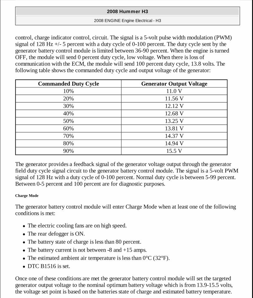
control, charge indicator control, circuit. The signal is a 5-volt pulse width modulation (PWM) signal of 128 Hz +/- 5 percent with a duty cycle of 0-100 percent. The duty cycle sent by the generator battery control module is limited between 36-90 percent. When the engine is turned OFF, the module will send 0 percent duty cycle, low voltage. When there is loss of communication with the ECM, the module will send 100 percent duty cycle, 13.8 volts. The following table shows the commanded duty cycle and output voltage of the generator:
The generator provides a feedback signal of the generator voltage output through the generator field duty cycle signal circuit to the generator battery control module. The signal is a 5-volt PWM signal of 128 Hz with a duty cycle of 0-100 percent. Normal duty cycle is between 5-99 percent. Between 0-5 percent and 100 percent are for diagnostic purposes.
Charge Mode
The generator battery control module will enter Charge Mode when at least one of the following conditions is met:
� The electric cooling fans are on high speed. � The rear defogger is ON. � The battery state of charge is less than 80 percent. � The battery current is not between -8 and +15 amps. � The estimated ambient air temperature is less than 0°C (32°F). � DTC B1516 is set.
Once one of these conditions are met the generator battery control module will set the targeted generator output voltage to the nominal optimum battery voltage which is from 13.9-15.5 volts, the voltage set point is based on the batteries state of charge and estimated battery temperature.
Commanded Duty Cycle Generator Output Voltage10% 11.0 V20% 11.56 V30% 12.12 V40% 12.68 V50% 13.25 V60% 13.81 V70% 14.37 V80% 14.94 V90% 15.5 V
2008 Hummer H3
2008 ENGINE Engine Electrical - H3
MY
Sunday, March 29, 2009 10:52:09 PM Page 166 © 2005 Mitchell Repair Information Company, LLC.
The battery voltage ramps up to the targeted set point at a rate of 20 mV per second.
Fuel Economy Mode
The generator battery control module will enter Fuel Economy Mode when all of the following conditions are true:
� Estimated ambient air temperature is equal to or greater than 0°C (32°F). � The calculated battery current is less than +15 amperes and greater than -8 amperes. � The battery state of charge is greater than or equal to 80 percent. � The rear defoggers are turned OFF. � The electric cooling fans are on low speed or OFF.
The targeted generator output voltage is 13 volts. The generator battery control module will exit this mode once the criteria are met for Charge Mode or it will boost voltage to a pre-determined set point for the fuel pump, headlamps, or windshield wipers.
Voltage Reduction Mode
The generator battery control module will enter Voltage Reduction Mode when the calculated ambient air temperature is above 0°C (32°F). The calculated battery current is less than 2 amperes and greater than -7 amperes, the generator field duty cycle is less than 99 percent. The rear defoggers are turned OFF, and the electric cooling fans are on low speed or OFF. Its targeted generator output voltage is 87 percent of the Charge Mode set point but limited to 12.9 volts. The generator battery control module will exit this mode once the criteria are met for Charge Mode or it will boost voltage to a pre-determined set point for the fuel pump, headlamps, or windshield wipers.
Start Up Mode
After the engine has started the generator battery control module sets a targeted generator output voltage of 14.5 volts for 30 seconds.
Headlamp Mode
The generator battery control module will enter the Headlamp Mode when the headlamps, low or high beams, are turned ON. The voltage will ramp up or down to 14.5 volts at a rate of 10 mV/second. The module will exit this mode once the headlamps are turned OFF and enter Charge Mode, Fuel Economy Mode, or Voltage Reduction Mode.
Battery Sulfation Mode
2008 Hummer H3
2008 ENGINE Engine Electrical - H3
MY
Sunday, March 29, 2009 10:52:09 PM Page 167 © 2005 Mitchell Repair Information Company, LLC.
The generator battery control module will enter this mode when the interpreted generator output voltage is less than 13.2 volts for 45 minutes. Once in this mode the generator battery control module will set the targeted output voltage to the nominal optimum battery voltage, see Charge Mode, for 3 minutes. The generator battery control module will then determine which mode to enter depending on vehicle conditions.
Windshield Wiper Voltage Boost Mode
When the generator battery control module is in Fuel Economy Mode or Voltage Reduction Mode, the module will boost battery voltage to 14.5 volts when the windshield wipers are ON, intermittent, low, or high speed, after 8 seconds. The voltage will ramp to 14.5 volts at a rate of 50 mV/second. The module will exit this mode once the Windshield Wipers are OFF for 5 seconds and the module will enter Charge Mode, Fuel Economy Mode, or Voltage Reduction Mode.
Fuel Pump Voltage Boost Mode
When the generator battery control module is in Fuel Economy Mode or Voltage Reduction Mode, the module will immediately boost battery voltage to 13.4 volts when the instantaneous fuel flow is greater than 21k grams/second and the throttle position sensor pedal position is greater than 90 percent. The module will exit this mode once the instantaneous fuel flow is less than 5k grams/second and enter Charge Mode, Fuel Economy Mode, or Voltage Reduction Mode.
De-Ice Voltage Boost Mode
The generator battery control module will enter De-Ice Voltage Boost Mode when the estimated ambient air temperature is less than or equal to -1°C (+30°F) and the engine coolant temperature is less than or equal to 75°C (167°F). The module will be in Charge Mode if the above conditions are true. Once the engine coolant temperature becomes greater than 75°C (167°F), the module will remain in Charge Mode or enter Fuel Economy Mode or Voltage Reduction Mode based on the vehicle conditions.
Instrument Panel Cluster (IPC) Operation
Charge Indicator Operation
The instrument panel cluster (IPC) illuminates the charge indicator in the message center when the one or more of the following occurs:
IMPORTANT: The generator battery control module is n ot set up to set a DTC if the battery voltage is too high or too low. Check w ith the ECM to
2008 Hummer H3
2008 ENGINE Engine Electrical - H3
MY
Sunday, March 29, 2009 10:52:09 PM Page 168 © 2005 Mitchell Repair Information Company, LLC.
� The IPC determines that the system voltage is less than 11 volts or greater than 16 volts. The IPC receives a class 2 message from the body control module (BCM) indicating there is a system voltage range concern.
� The IPC performs the displays test at the start of each ignition cycle. The indicator illuminates for approximately 3 seconds.
� The ignition is ON, with the engine OFF. � The generator battery control module determines there is a fault and sends a class 2 message
to the IPC to illuminate the charge indicator.
Charging System Failure
The generator battery control module will send a message to the IPC for the CHARGING SYSTEM FAILURE message to be displayed. It is commanded ON when DTC B1487 sets. The message is turned off when the conditions for clearing the DTC have been met and after an ignition cycle.
Service Charging System
The generator battery control module will send a class 2 message to the IPC for the SERVICE CHARGING SYSTEM message to be displayed. It is commanded ON when DTC B1390, B1488, B1492, or B1516 sets. The message is turned OFF when the conditions for clearing the DTC have been met and after an ignition cycle.
Voltmeter Operation
The IPC displays the system voltage as detected at the ignition 1 input of the IPC. When the engine is ON, the gage should be between 10-16 volts. The voltmeter will be noticeably different than previous model year vehicle as far as voltage fluctuations. If there is a concern with gage operation ensure to compare to a known good like vehicle.
ELECTRICAL POWER MANAGEMENT DESCRIPTION AND OPERATI ON
Electrical Power Management
The electrical power management (EPM) is used to monitor and control the charging system and alert the driver of possible problems within the charging system. The EPM system makes the most efficient use of the generator output, improves the battery state of charge (SOC), extends battery life.
see if they set a DTC when the battery voltage is t oo high or too low.
2008 Hummer H3
2008 ENGINE Engine Electrical - H3
MY
Sunday, March 29, 2009 10:52:09 PM Page 169 © 2005 Mitchell Repair Information Company, LLC.
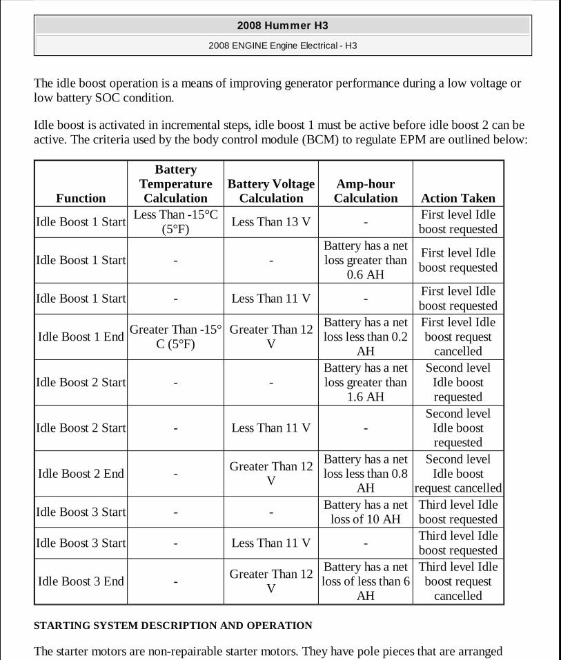
The idle boost operation is a means of improving generator performance during a low voltage or low battery SOC condition.
Idle boost is activated in incremental steps, idle boost 1 must be active before idle boost 2 can be active. The criteria used by the body control module (BCM) to regulate EPM are outlined below:
STARTING SYSTEM DESCRIPTION AND OPERATION
The starter motors are non-repairable starter motors. They have pole pieces that are arranged
Function
Battery Temperature Calculation
Battery Voltage Calculation
Amp-hour Calculation Action Taken
Idle Boost 1 StartLess Than -15°C
(5°F)Less Than 13 V -
First level Idle boost requested
Idle Boost 1 Start - -Battery has a net loss greater than
0.6 AH
First level Idle boost requested
Idle Boost 1 Start - Less Than 11 V -First level Idle boost requested
Idle Boost 1 EndGreater Than -15°
C (5°F)Greater Than 12
V
Battery has a net loss less than 0.2
AH
First level Idle boost request
cancelled
Idle Boost 2 Start - -Battery has a net loss greater than
1.6 AH
Second level Idle boost requested
Idle Boost 2 Start - Less Than 11 V -Second level
Idle boost requested
Idle Boost 2 End -Greater Than 12
V
Battery has a net loss less than 0.8
AH
Second level Idle boost
request cancelled
Idle Boost 3 Start - -Battery has a net loss of 10 AH
Third level Idle boost requested
Idle Boost 3 Start - Less Than 11 V -Third level Idle boost requested
Idle Boost 3 End -Greater Than 12
V
Battery has a net loss of less than 6
AH
Third level Idle boost request
cancelled
2008 Hummer H3
2008 ENGINE Engine Electrical - H3
MY
Sunday, March 29, 2009 10:52:09 PM Page 170 © 2005 Mitchell Repair Information Company, LLC.
around the armature. Both solenoid windings are energized. The pull-in winding circuit is completed to the ground through the starter motor. The windings work together magnetically to pull and hold in the plunger. The plunger moves the shift lever. This action causes the starter drive assembly to rotate on the armature shaft spline as it engages with the flywheel ring gear on the engine. Moving at the same time, the plunger also closes the solenoid switch contacts in the starter solenoid. Full battery voltage is applied directly to the starter motor and it cranks the engine.
As soon as the solenoid switch contacts close, current stops flowing thorough the pull-in winding because battery voltage is applied to both ends of the windings. The hold-in winding remains energized. Its magnetic field is strong enough to hold the plunger, shift lever, starter drive assembly, and solenoid switch contacts in place to continue cranking the engine. When the engine starts, pinion overrun protects the armature from excessive speed until the switch is opened.
When the ignition switch is released from the START position, the PCM CNTRL relay opens and battery voltage is removed from the starter solenoid terminal A X1. Current flows from the motor contacts through both windings to the ground at the end of the hold-in winding. However, the direction of the current flow through the pull-in winding is now opposite the direction of the current flow when the winding was first energized.
The magnetic fields of the pull-in and hold-in windings now oppose one another. This action of the windings, along with the help of the return spring, causes the starter drive assembly to disengage and the solenoid switch contacts to open simultaneously. As soon as the contacts open, the starter circuit is turned off.
Circuit Description (Key Start)
When the ignition switch is placed in the Start position, a discrete signal is supplied to the body control module (BCM) notifying it that the ignition is in the start position. The BCM then sends a message to the engine control module (ECM) notifying it that crank has been requested. The ECM verifies that the transmission is in Park or Neutral. If it is, the ECM then supplies 12 volts to the control circuit of the PCM CNTRL relay. When this occurs, battery positive voltage is supplied through the switch side of the PCM CNTRL relay to terminal A X1 of the starter solenoid.
SPECIAL TOOLS AND EQUIPMENT
SPECIAL TOOLS
Illustration Tool Number/Description
2008 Hummer H3
2008 ENGINE Engine Electrical - H3
MY
Sunday, March 29, 2009 10:52:09 PM Page 171 © 2005 Mitchell Repair Information Company, LLC.
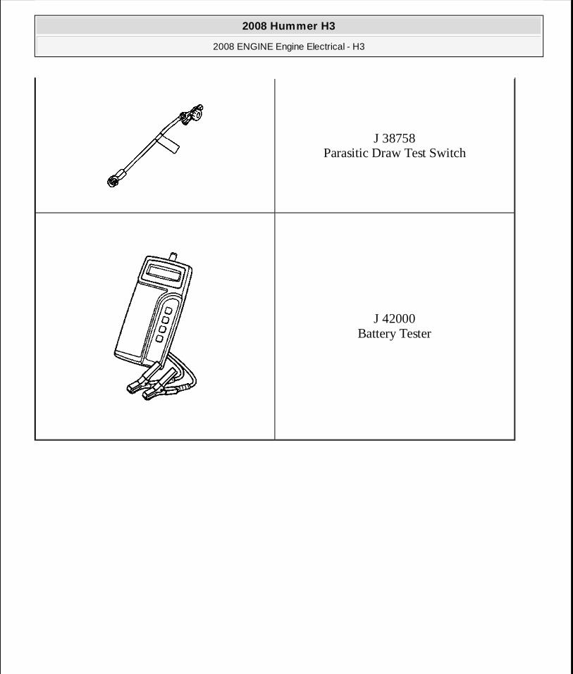
J 38758 Parasitic Draw Test Switch
J 42000 Battery Tester
2008 Hummer H3
2008 ENGINE Engine Electrical - H3
MY
Sunday, March 29, 2009 10:52:09 PM Page 172 © 2005 Mitchell Repair Information Company, LLC.