Specifications, Guidelines & Practices - Repeater · PDF fileLBI-39184A ericssonz...
32
LBI-39184A ericssonz Specifications, Guidelines & Practices Concrete Shelter Specifications “Bullet Resistant”
Transcript of Specifications, Guidelines & Practices - Repeater · PDF fileLBI-39184A ericssonz...
LBI-39184A
ericssonz
Specifications, Guidelines& Practices
Concrete Shelter Specifications“Bullet Resistant”

LBI-39184A
2
TABLE OF CONTENTS
Page
1.0 GENERAL..............................................................................................................................................................3
2.0 SPECIFIC CONDITIONS......................................................................................................................................3
3.0 SHELTER SPECIFICATIONS ..............................................................................................................................3
4.0 ENVIRONMENTAL CONDITIONS.....................................................................................................................5
5.0 ELECTRICAL AND LIGHTING...........................................................................................................................5
6.0 ALARMS AND FIRE PROTECTION...................................................................................................................6
7.0 GROUNDING SYSTEM .......................................................................................................................................7
8.0 QUALITY ASSURANCE ......................................................................................................................................7
9.0 DOCUMENTATION .............................................................................................................................................7
10.0 CERTIFICATION ................................................................................................................................................8
11.0 INSTRUCTIONS TO BIDDERS .........................................................................................................................8
Copyright August 1995, Ericsson Inc.
NOTICE!This manual covers Ericsson and General Electric products manufactured and sold by Ericsson Inc.
This manual is published by Ericsson Inc., without any warranty. Improvements and changes to this manual necessitated by typographical errors,inaccuracies of current information, or improvements to programs and/or equipment, may be made by Ericsson Inc., at any time and without notice. Suchchanges will be incorporated into new editions of this manual. No part of this manual may be reproduced or transmitted in any form or by any means,electronic or mechanical, including photocopying and recording, for any purpose, without the express written permission of Ericsson Inc.
LBI-39184A
3
1.0 GENERAL
1.1 This statement of work and specifications are forshelter (s) to be supplied to Ericsson Inc. PrivateRadio Systems. The shelter shall be a prefabricatedconcrete communication type as manufactured byAndrew, Rohn, VFP or an Ericsson Inc. approvedequivalent. The specifications in this document areintended to set a minimum level which can bemodified to meet specific program requirements.
1.2 The specifications contained herein encompass thelabor, equipment and materials for a prefabricatedconcrete communications shelter. The shelter structureshall be bullet resistant withstanding 30/06 rifle fire ata distance of 15 feet per UL 752 standards. Theshelter shall be vandal resistant and be constructed ofsteel reinforced concrete. The shelter structure shallprovide a 2-hour fire rating as defined by the UniformBuilding Code and meet Zone 4 seismic requirements.The shelter shall be designed for the explicit use ofhousing electronic equipment within a controlledatmosphere required for the proper conditions fortransmitting and receiving equipment.
1.3 Shelters shall incorporate non-porous wall and roofsections, to preclude capillary action, and shall be sodesigned, and constructed to provide a minimumuseful life period of 20 years, without need for majormaintenance actions. Manufacturer shall provideshelter maintenance and warranty information.
1.4 Shelter manufacturer shall supply and install completeAC wiring systems as required by this specificationand in compliance to applicable codes. Electricalsystems shall be designed based on preliminary floorplan provided by Ericsson Inc.
1.5 Manufacturer shall supply and install complete airconditioning and heating systems as required tocomply with the environmental conditions of thesespecifications.
1.6 Manufacturer shall be responsible for transporting orfor supervising the transporting of a shelter or sheltersto their respective sites.
1.7 Manufacturer shall design an I-beam skid assembly, ifrequired for transportation to site, based on therequirements of this specification and install the shelteron the assembly. Fabricator will submit I-beamassembly drawings within 10 days after receipt oforder.
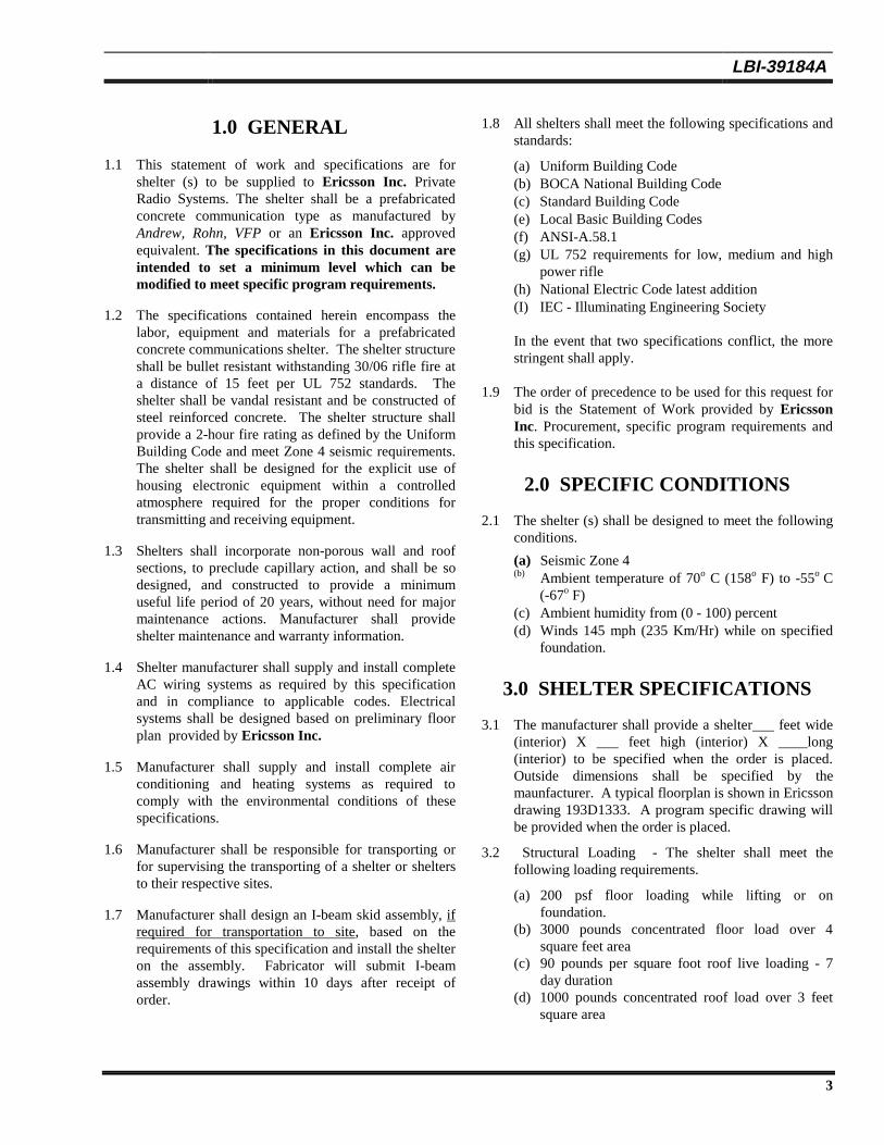
1.8 All shelters shall meet the following specifications andstandards:
(a) Uniform Building Code(b) BOCA National Building Code(c) Standard Building Code(e) Local Basic Building Codes(f) ANSI-A.58.1(g) UL 752 requirements for low, medium and high
power rifle(h) National Electric Code latest addition(I) IEC - Illuminating Engineering Society
In the event that two specifications conflict, the morestringent shall apply.
1.9 The order of precedence to be used for this request forbid is the Statement of Work provided by EricssonInc. Procurement, specific program requirements andthis specification.
2.0 SPECIFIC CONDITIONS
2.1 The shelter (s) shall be designed to meet the followingconditions.
(a) Seismic Zone 4(b) Ambient temperature of 70o C (158o F) to -55o C
(-67o F)(c) Ambient humidity from (0 - 100) percent(d) Winds 145 mph (235 Km/Hr) while on specified
foundation.
3.0 SHELTER SPECIFICATIONS
3.1 The manufacturer shall provide a shelter___ feet wide(interior) X ___ feet high (interior) X ____long(interior) to be specified when the order is placed.Outside dimensions shall be specified by themaunfacturer. A typical floorplan is shown in Ericssondrawing 193D1333. A program specific drawing willbe provided when the order is placed.
3.2 Structural Loading - The shelter shall meet thefollowing loading requirements.
(a) 200 psf floor loading while lifting or onfoundation.
(b) 3000 pounds concentrated floor load over 4square feet area
(c) 90 pounds per square foot roof live loading - 7day duration
(d) 1000 pounds concentrated roof load over 3 feetsquare area

LBI-39184A
4
3.3 Thermal Performance - Overall u factor < .08 Btu/hr/degrees F
3.4 Operating Environment - The shelter shall be sealed toresist dust infiltration and be watertight.
3.5 Shelter Construction - The shelter shall be precast,preassembled steel reinforced solid concrete. Panel topanel connections to be welded. Manufacture of theprecast concrete elements shall occur in a suitableenvironment (enclosed building preferred).Manufacturer must have a minimum of one ACICertified Level 1 Concrete Technician supervising theplacing of concrete in the forms.
Floor Section:Floor section shall be an 8-inch waffled structuralprecast steel reinforced concrete section. Ribs shall be2’-0” O.C. transverse and 4’-0” O.C. longitudinal. Allsurfaces shall be smooth. The interior surface shall becovered with 1/8 inch light colored industrial vinylfloor covering, bonded with a waterproof contactadhesive. The floor shall be supplied with provisionsfor customer anchoring of equipment.
Roof Section:The roof section shall be a minimum of steelreinforced 4” solid concrete with 1/8” per footdrainage slope. Ceiling insulation and finish to befoamboard insulation with 3/8” vinyl coated board.Plastic joint or corner trim shall be installed at allpanel joints. The roof shall provide at least a 2”overhang on all sides. The roof will be a hip typesloping two (2) directions. It shall be a cap and fitover the walls, leaving no exposed roof to wall joint.
Wall Sections:Wall section shall be 4” solid steel reinforced concretewith an exterior exposed aggregate finish. Wallinsulation and finish shall be foamboard insulationcovered with 3/4” thick board, surfaced with fiberglassreinforced plastic. Plastic joint or corner shall beinstalled at all panel joints. Floor to wall intersectionshall be finished with 4” vinyl baseboard. Theconcrete walls shall overhang the concrete floor aminimum of 7” from the top concrete floor surface.There shall be no exposed wall to floor joint. Insidewalls shall be finished with a smooth surface and lightin color to permit maximum utilization of availablelight, and shall be designed to support customer loadsas specified.
Steel Reinforcing:Steel reinforcing to be as per manufacturer’sengineered structural analysis.
Insulation:Standard wall and ceiling insulation shall befoamboard. The insulation R-value shall be consistentwith the thermal performance specified in paragraph3.3.
3.6 Sealing - All joints shall be sealed with a compressible,resilient sealant. There shall be no exposed roof towall or wall to floor exterior joint sealants. Wall towall, wall to roof, and wall to floor seals shall beinternal.
Exterior Walls:Surface of walls to be sealed with two coats ofThoroglaze H Sealer and a top coat of Thorosystem’sThorosheen Sealer or equivalent.
3.7 Material Specification - The material specificationsshall be as follows.
ConcreteCompressive strength shall be 4000 PSI at 28 days.Mix design of 114-118 lb/cu. ft. structural lightweightconcrete expanded shale or expanded clay aggregate ispreferred. Mix shall be homogenous. Seeding ofaggregate for exposed aggregate finish is not allowed.Cement used in concrete shall be standard Portlandcement conforming to the requirement of the “StandardSpecifications for Portland Cement”, ASTMDesignation C150.
Concrete aggregates shall conform to one of thefollowing specifications:
1. “Specifications for Concrete Aggregates”,ASTM Designation: C33.
2. “Specifications for LightweightAggregates for Structural Concrete”, ASTMDesignation C30.
Other Materials Water shall be free from injurious quantities of oil,
alkali, vegetable matter and salt. Non-potable watershall not be used in mixing concrete. Reinforcementbars shall be deformed steel bars conforming to therequirements of the “Specifications for Deformed andPlain Billet-Steel Bars for Concrete Reinforcement”,ASTM Designation: A615.
Welded smooth wire fabric shall be steel wire fabricconforming to the requirements of the “Specificationsfor Welded Steel Wire Fabric for ConcreteReinforcement”, ASTM Designation: A185.
The plywood panels shall be in accordance withstressed-skin panel design of the Timber Design andConstruction Handbook.
LBI-39184A
5
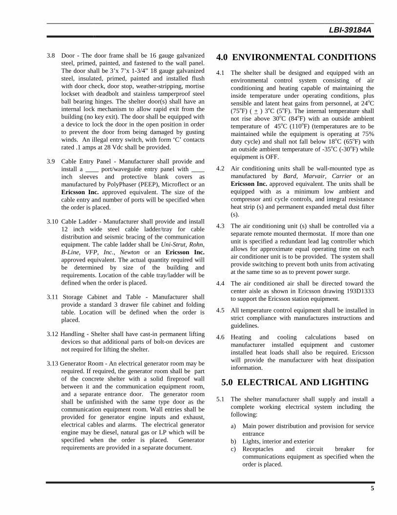
3.8 Door - The door frame shall be 16 gauge galvanizedsteel, primed, painted, and fastened to the wall panel.The door shall be 3’x 7’x 1-3/4” 18 gauge galvanizedsteel, insulated, primed, painted and installed flushwith door check, door stop, weather-stripping, mortiselockset with deadbolt and stainless tamperproof steelball bearing hinges. The shelter door(s) shall have aninternal lock mechanism to allow rapid exit from thebuilding (no key exit). The door shall be equipped witha device to lock the door in the open position in orderto prevent the door from being damaged by gustingwinds. An illegal entry switch, with form ‘C’ contactsrated .1 amps at 28 Vdc shall be provided.
3.9 Cable Entry Panel - Manufacturer shall provide andinstall a ____ port/waveguide entry panel with ____inch sleeves and protective blank covers asmanufactured by PolyPhaser (PEEP), Microflect or anEricsson Inc. approved equivalent. The size of thecable entry and number of ports will be specified whenthe order is placed.
3.10 Cable Ladder - Manufacturer shall provide and install12 inch wide steel cable ladder/tray for cabledistribution and seismic bracing of the communicationequipment. The cable ladder shall be Uni-Strut, Rohn,B-Line, VFP, Inc., Newton or an Ericsson Inc.approved equivalent. The actual quantity required willbe determined by size of the building andrequirements. Location of the cable tray/ladder will bedefined when the order is placed.
3.11 Storage Cabinet and Table - Manufacturer shallprovide a standard 3 drawer file cabinet and foldingtable. Location will be defined when the order isplaced.
3.12 Handling - Shelter shall have cast-in permanent liftingdevices so that additional parts of bolt-on devices arenot required for lifting the shelter.
3.13 Generator Room - An electrical generator room may berequired. If required, the generator room shall be partof the concrete shelter with a solid fireproof wallbetween it and the communication equipment room,and a separate entrance door. The generator roomshall be unfinished with the same type door as thecommunication equipment room. Wall entries shall beprovided for generator engine inputs and exhaust,electrical cables and alarms. The electrical generatorengine may be diesel, natural gas or LP which will bespecified when the order is placed. Generatorrequirements are provided in a separate document.
4.0 ENVIRONMENTAL CONDITIONS
4.1 The shelter shall be designed and equipped with anenvironmental control system consisting of airconditioning and heating capable of maintaining theinside temperature under operating conditions, plussensible and latent heat gains from personnel, at 24oC(75oF) ( + ) 3oC (5oF). The internal temperature shallnot rise above 30oC (84oF) with an outside ambienttemperature of 45oC (110oF) (temperatures are to bemaintained while the equipment is operating at 75%duty cycle) and shall not fall below 18oC (65oF) withan outside ambient temperature of -35oC (-30oF) whileequipment is OFF.
4.2 Air conditioning units shall be wall-mounted type asmanufactured by Bard, Marvair, Carrier or anEricsson Inc. approved equivalent. The units shall beequipped with as a minimum low ambient andcompressor anti cycle controls, and integral resistanceheat strip (s) and permanent expanded metal dust filter(s).
4.3 The air conditioning unit (s) shall be controlled via aseparate remote mounted thermostat. If more than oneunit is specified a redundant lead lag controller whichallows for approximate equal operating time on eachair conditioner unit is to be provided. The system shallprovide switching to prevent both units from activatingat the same time so as to prevent power surge.
4.4 The air conditioned air shall be directed toward thecenter aisle as shown in Ericsson drawing 193D1333to support the Ericsson station equipment.
4.5 All temperature control equipment shall be installed instrict compliance with manufactures instructions andguidelines.
4.6 Heating and cooling calculations based onmanufacturer installed equipment and customerinstalled heat loads shall also be required. Ericssonwill provide the manufacturer with heat dissipationinformation.
5.0 ELECTRICAL AND LIGHTING
5.1 The shelter manufacturer shall supply and install acomplete working electrical system including thefollowing:
a) Main power distribution and provision for serviceentrance
b) Lights, interior and exteriorc) Receptacles and circuit breaker for
communications equipment as specified when theorder is placed.
LBI-39184A
6
d) Receptacles for customer and user test-equipmentshall be on separate circuits.
e) Heating and coolingf) Conduit, fittings and wiringg) Lightning and surge protection
Generator transfer switch, if required
5.2 All equipment and materials furnished and installedshall be new and of the highest quality, and shall bestandard products of manufacturers regularly engagedin the production of such equipment and materials.Materials shall also be of the latest standard design,and shall be Underwriters Labrotories (UL) listedwhere applicable.
5.3 Installation shall comply with the latest edition of theUSA National Electric Code, NFPA 70.
5.4 Electrical System (Minimum Requirement) -The manufacturer shall supply a minimum of 200ampere, 120/240 VAC, single phase, 60 Hz, orequivalent power with main breaker, snap-in utilitypower distribution panel as manufactured by GeneralElectric, or an Ericsson Inc. approved equivalent.The enclosures shall be NEMA 1 surface mounted.Electrical installation and wiring shall conform to thelatest edition of the National Electrical Code and shallconsist of the following as a minimum: surfacemounted EMT conduit: grounded duplex outlets, oneevery 4 feet on 3 walls; fluorescent lights (two lamptype fixtures) as required with inside switch; 200 AMP120/240 VAC main; 20, 30, or 40 position breaker boxwith a minimum of 16 single pole 20 AMP breakers(as required).
5.5 Circuit breakers for all manufacturer installedequipment and customer loads shall also be provided.
5.6 Manufacturer shall provide and install a Joslyn Model1265-85, PolyPhaser IS-PM240-BP or Ericsson Inc.approved equivalent, AC surge arrester for connectionto the incoming power lines.
5.7 A rigid metal conduit, shall be provided and sizedaccordingly for the service entrance conductors.
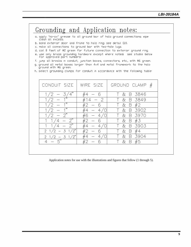
5.8 All interior shelter wiring shall be installed in surfacemounted electrical metallic tubing (E.M.T.), Article348 of the USA National Electric Code shall apply.Other application notes are illustrated in Figure 5.
5.9 All conductors shall be properly sized and rated for theload and application, and, shall be no smaller than # 12AWG. Conductors shall be copper, type THHN.
5.10 The splicing of conductor wires should be kept to aminimum. Where splices are required, wire nuts shall
be used and shall be properly sized, insulated typeconnectors.
5.11 Conductors shall be continuous from outlet to outlet.Splices shall be made within outlet boxes or junctionboxes only.
5.12 A minimum of 6 inches of extra conductor wire shallbe provided at each outlet to make splices or joints,except where it is intended to loop through sockets,receptacles and other fixtures without splices or joints.
5.13 Receptacles shall be rated 20 amp, 120V, 3 wire,grounding type, specification grade duplex and shallbe on separate circuits. In applications where cabinetpower is fed from overhead receptacles, the outletsshall be the twist-loc type. This “twist-loc” (L5-20Ror equivalent) receptacle will be defined as part of theoriginal drawings. The number of outlets, locations,and positions will also be defined. Typical spacing forduplex wall outlets is (4) four-foot intervals at 18inches above finished floor level, except wherespecified otherwise.
5.14 Manufacturer shall provide a lighting systemconsisting of quality grade 80 watt surface mountedfluorescent light fixtures equipped with lexan typediffusers, RFI noise suppression filters. The systemshall be designed to provide as a minimumillumination of 70 foot candles (fc) at 36 inches abovethe floor. The fixture shall be installed taking intoconsideration the location of the communications racksand equipment.
5.15 Exterior lighting shall consist of a 75 wattincandescent bulb. The fixture(s) shall be suppliedwith vandal resistant lens and photo cell with a switchoverride.
6.0 ALARMS AND FIREPROTECTION
6.1 Form “C” type contact alarms shall be provided for thefollowing functions:
a) Door entry alarmb) Smoke alarmc) Low temperature alarmd) High temperature alarme) Air conditioner fail alarmf) Power fail alarmg) Generator alarms, if required
The alarm contacts shall be rated for 0.1 amps at 28Vdc.
LBI-39184A
7
6.2 A 4’ x 4’ wall mounted Telco/alarm board shall beprovided for punchblock mounting. The shelter alarmsshall be wired to a Type 66 block on the Telco/alarmboard.
6.3 The minimum fire protection required for the shelter isa smoke alarm and a Class ABC fire extinguisher. Anautomatic fire suppression may also be required.
7.0 GROUNDING SYSTEM
7.1 Grounding of the communications shelter must beconsistant with the ERICSSON groundingrequirements for communications sites and shelters asdefined in LBI-39067.
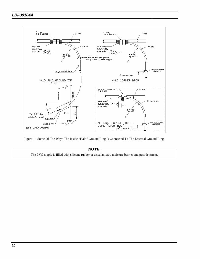
7.2 The manufacturer shall install a “halo” ground systemconsisting of a #2 AWG stranded green insulatedcopper halo located approximately 6 inches below theceiling (see Figure 2 or the Ericsson GroundingGuidelines & Practices, LBI-39067A) with vertical #2AWG bare/tinned solid copper drops at each corner ofthe building (see Figure 1 e.g. “PVC” Nipple). Atthese drop locations a length of bare/tinned solidcopper wire capable of extending through and beyondthe PVC nipple at least 10 feet shall be coiled andsecured to the wall. The customer will use these toconnect to the on site grounding system.
7.3 The shelter floor will be supplied with penetrations asper Figure 1 to allow the customer to exit at eachcorner wall location with the #2 AWG halo ground.Silicone sealer or equivalent shall be supplied forcustomers use to seal these penetrations aftergrounding connections have been made. An internalshelter “ground-bar” shall be installed as described inFigure 3.
7.4 Cable trays, ladders, and metal doors shall be bondedto the internal ground ring as illustrated in Figure 4.
7.5 Conduits and conduit couplings shall be bonded to theground system in a manner consistent with attachedFigure 5.
7.6 All coax cable and/or waveguide entry grounds willterminate at the “ground window” or a PolyPhaserEarthed Entry Panel (PEEP) ground bar installed inan area near to, and/or below the cable multi-port entrypanel. A description and example of the ground bar isillustrated in Figure 3.
Installation and wire attachment notes areprovided on the drawing. Use of the “anti-oxidant” at all dissimilar metal connections ishighly recommended!
NOTE
7.7 Grounding of electrical power and surge suppressionequipment shall be done in strict compliance to thelatest edition of the National Electric Code andmanufacturers data.
8.0 QUALITY ASSURANCE
8.1 The shelter manufacturer shall have a quality assuranceprogram to ensure that its buildings meet the industrystandards. Through this program incoming and inprocess inspections, components, assemblies, andfinished shelters shall be checked for compliance withcustomer specifications, engineering specifications anddrawings. An inspection log shall also be maintainedwith inspection disposition recorded by the QualityAssurance inspector. These records shall be availablefor inspection upon request. The major inspectioncategories are I-beam skid, framing, assembly,concrete, steel assembly, electrical, finish, groundingand preparation for shipping.
8.2 All equipment and hardware shall be installed in theshelter using best commercial practices. All wall andfloor mounted equipment shall present a neat andsymmetrical appearance and shall be installed towithstand shock and vibration due to shipping.
8.3 Shelter and accessories, when finished, shall becomplete in every respect and ready for use intended.
9.0 DOCUMENTATION
9.1 Manufacturer shall submit, after receipt of order,preliminary drawings and documentation consisting asa minimum the following.
(a) Shelter layout and structural dimensions. Includedshall be drawings and applicable data onequipment included as part of the shelter.
(b) A legend which identifies major components andsystems.
LBI-39184A
8
9.2 Ericsson Inc. will after receipt of preliminarydrawings and design information review and approveand return one signed copy with one of the following:
(a) Approved: Prints so marked will authorize themanufacturer to proceed with fabrication of theshelter.
(b) Approved as noted: Prints so marked willauthorize the manufacturer to proceed with thefabrication of the shelter only after the necessarycorrections to drawing have been completed.
(c) Not approved: The manufacturer shall make thecorrections on the drawings and will be requiredto resubmit for customer approval. The timerequired for such resubmitals of drawings does notentitle the manufacturer to any extension of time.However, customer may grant extension uponrequest if time permits.
Construction of the shelter shall not beginuntil customer acceptance of the preliminarydrawings.
NOTE
9.3 The manufacturer shall also provide upon completionthe following:
(a) One set of “as-built” drawings and parts list shallbe completed and provided with a shelter onshipment. An Operation and Maintenance Manualshall be provided with each shelter system.Included in this manual as a minimum will bemanufacturers data and warranty information onall available electrical systems and suppliedequipment. Shelter start-up information andmaintenance procedures are also to be provided.
(b) Manufacturer shall provide quality assuranceacceptance documentation on completion of theshelter.
10.0 CERTIFICATION
10.1 Ericsson Inc. will provide the manufacturer the finalsite information with purchase order.
10.2 It is the manufacturers responsibility to supplyEricsson Inc. with any necessary approval or statecertification that may be required, PE sealed drawingsup to six (6) sets may also be requested.
11.0 INSTRUCTIONS TO BIDDERS
11.1 The shelter bidder will submit the followinginformation with his proposal:
(a) Price(b) Delivery schedule(c) Shipping cost (separately)(d) Verification that the shelter will be approved in
the State where required.
11.2 The manufacturer will guarantee that all materials andworkmanship shall be free from defect for a period oftwo (2) year after delivery.
11.3 The manufacturer will guarantee the shelterconstruction for a period of five (5) years aftercompletion.
11.4 The manufacturer will address each paragraph of thisspecification and explain their compliance orexceptions.
11.5 Technical questions regarding this specification shouldbe sent to:
Ericsson Inc.Private Radio SystemsCSC Bldg, Mountain View RoadLynchburg, Virginia 24502
Attention: G. E. “Buck” Rogers SRTelephone: (804) 528-7836Fax: (804) 528-7129
LBI-39184A
9
Application notes for use with the illustrations and figures that follow (1 through 5).
LBI-39184A
10
Figure 1 - Some Of The Ways The Inside “Halo” Ground Ring Is Connected To The External Ground Ring.
The PVC nipple is filled with silicone rubber or a sealant as a moisture barrier and pest deterrent.
NOTE
LBI-39184A
11
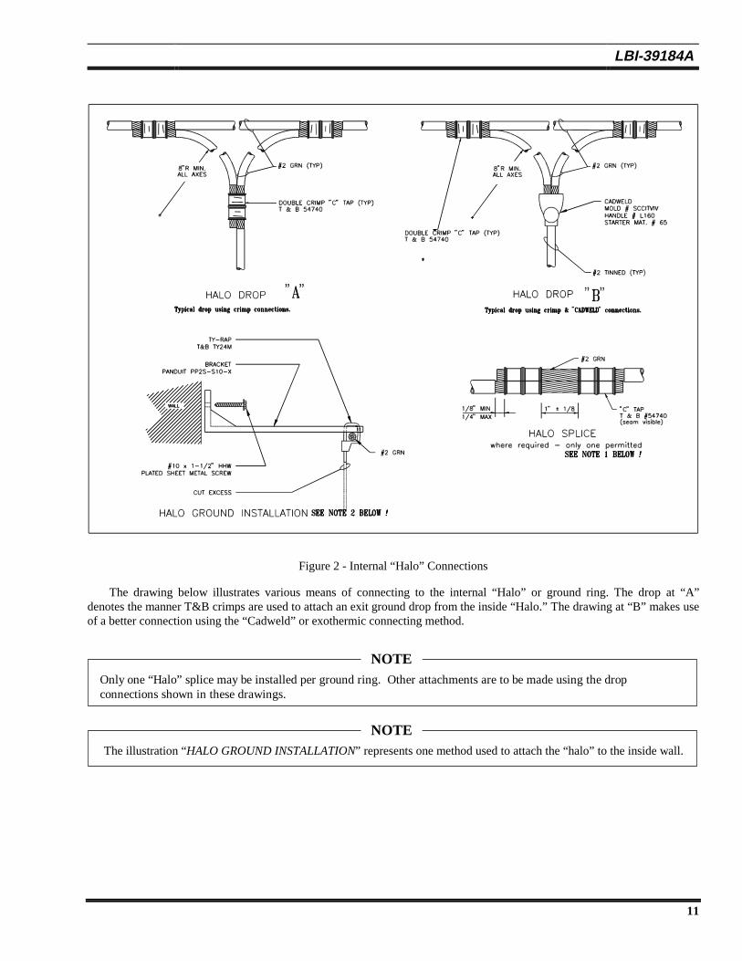
Figure 2 - Internal “Halo” Connections
The drawing below illustrates various means of connecting to the internal “Halo” or ground ring. The drop at “A”denotes the manner T&B crimps are used to attach an exit ground drop from the inside “Halo.” The drawing at “B” makes useof a better connection using the “Cadweld” or exothermic connecting method.
Only one “Halo” splice may be installed per ground ring. Other attachments are to be made using the dropconnections shown in these drawings.
NOTE
The illustration “HALO GROUND INSTALLATION” represents one method used to attach the “halo” to the inside wall.
NOTE
LBI-39184A
12
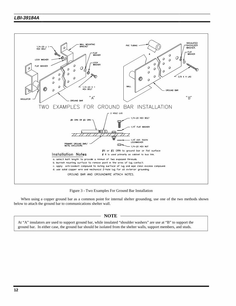
Figure 3 - Two Examples For Ground Bar Installation
When using a copper ground bar as a common point for internal shelter grounding, use one of the two methods shownbelow to attach the ground bar to communications shelter wall.
At “A” insulators are used to support ground bar, while insulated “shoulder washers” are use at “B” to support theground bar. In either case, the ground bar should be isolated from the shelter walls, support members, and studs.
NOTE
LBI-39184A
13
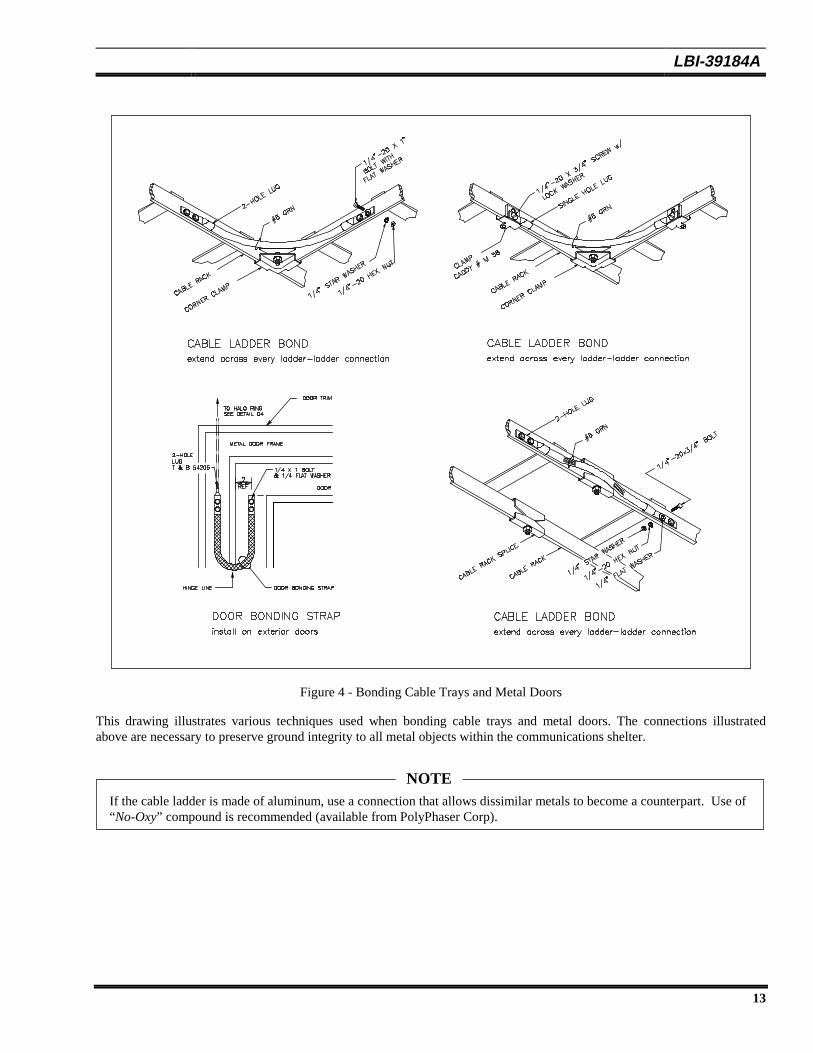
Figure 4 - Bonding Cable Trays and Metal Doors
This drawing illustrates various techniques used when bonding cable trays and metal doors. The connections illustratedabove are necessary to preserve ground integrity to all metal objects within the communications shelter.
If the cable ladder is made of aluminum, use a connection that allows dissimilar metals to become a counterpart. Use of“No-Oxy” compound is recommended (available from PolyPhaser Corp).
NOTE
LBI-39184A
14
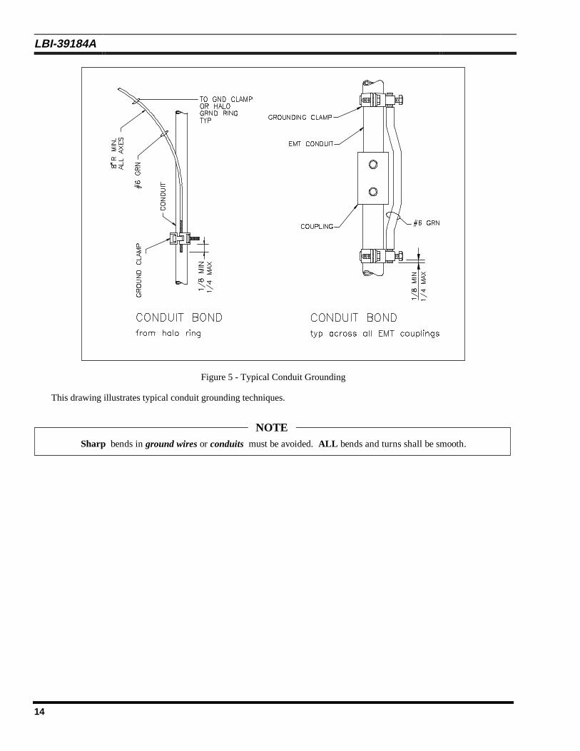
Figure 5 - Typical Conduit Grounding
This drawing illustrates typical conduit grounding techniques.
Sharp bends in ground wires or conduits must be avoided. ALL bends and turns shall be smooth.
NOTE
LBI-39184A
15
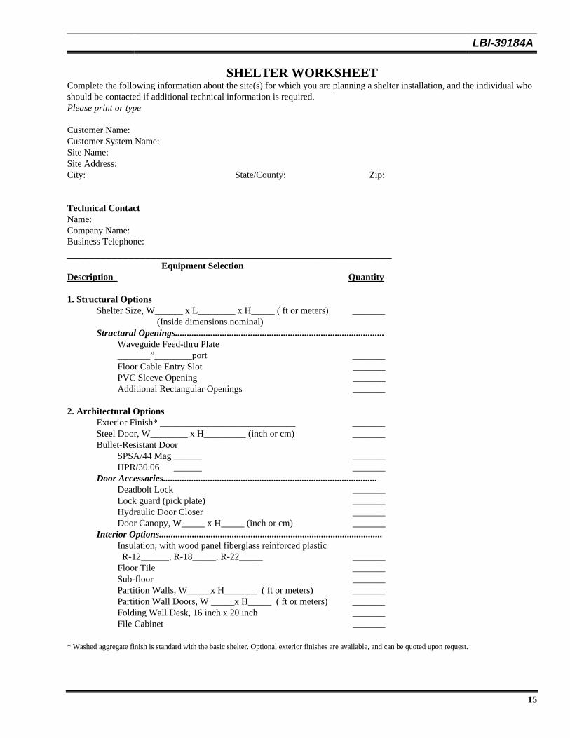
SHELTER WORKSHEETComplete the following information about the site(s) for which you are planning a shelter installation, and the individual whoshould be contacted if additional technical information is required.Please print or type
Customer Name:Customer System Name:Site Name:Site Address:City: State/County: Zip:
Technical ContactName:Company Name:Business Telephone:__________________________________________________________
Equipment SelectionDescription Quantity
1. Structural OptionsShelter Size, W______ x L________ x H_____ ( ft or meters) _______
(Inside dimensions nominal)Structural Openings.........................................................................................
Waveguide Feed-thru Plate_______”________port _______Floor Cable Entry Slot _______PVC Sleeve Opening _______Additional Rectangular Openings _______
2. Architectural OptionsExterior Finish* _____________________________ _______Steel Door, W________ x H_________ (inch or cm) _______Bullet-Resistant Door
SPSA/44 Mag ______ _______HPR/30.06 ______ _______
Door Accessories...........................................................................................Deadbolt Lock _______Lock guard (pick plate) _______Hydraulic Door Closer _______Door Canopy, W_____ x H_____ (inch or cm) _______
Interior Options...............................................................................................Insulation, with wood panel fiberglass reinforced plastic R-12______, R-18_____, R-22_____ _______Floor Tile _______Sub-floor _______Partition Walls, W_____x H_______ ( ft or meters) _______Partition Wall Doors, W _____x H_____ ( ft or meters) _______Folding Wall Desk, 16 inch x 20 inch _______File Cabinet _______
* Washed aggregate finish is standard with the basic shelter. Optional exterior finishes are available, and can be quoted upon request.
LBI-39184A
16
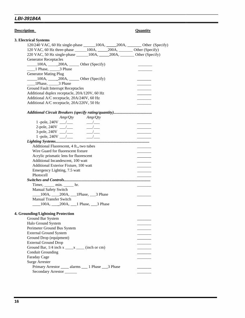
Description Quantity
3. Electrical Systems120/240 VAC, 60 Hz single-phase ______100A, _____200A, _______ Other (Specify)120 VAC, 60 Hz three-phase ______100A, _____200A, _______ Other (Specify)
220 VAC, 50 Hz single-phase ______100A, _____200A, _______ Other (Specify)Generator Receptacles_____100A, _____200A, _____ Other (Specify) ___________1 Phase, _____3 Phase _______Generator Mating Plug_____100A, _____200A, _____ Other (Specify) ___________1Phase, _____3 Phase _______Ground Fault Interrupt Receptacles _______Additional duplex receptacle, 20A/120V, 60 Hz _______Additional A/C receptacle, 20A/240V, 60 Hz _______Additional A/C receptacle, 20A/220V, 50 Hz _______
Additional Circuit Breakers (specify rating/quantity)......................................Amp/Qty Amp/Qty
1 -pole, 240V ___/___ ___/___ _______2-pole, 240V ___/___ ___/___ _______3-pole, 240V ___/___ ___/___ _______1 -pole, 240V ___/___ ___/___ _______
Lighting Systems.............................................................................................Additional Fluorescent, 4 ft., two tubes _______Wire Guard for fluorescent fixture _______Acrylic prismatic lens for fluorescent _______Additional Incandescent, 100 watt _______Additional Exterior Fixture, 100 watt _______Emergency Lighting, 7.5 watt _______Photocell _______
Switches and Controls......................................................................................Timer, _____ min. _____ hr. _______Manual Safety Switch____100A, ____200A, ___1Phase, ___3 Phase _______Manual Transfer Switch____100A, ____200A, ___1 Phase, ___3 Phase _______
4. Grounding/Lightning ProtectionGround Bar System _______Halo Ground System _______Perimeter Ground Bus System _______External Ground System _______Ground Drop (equipment) _______External Ground Drop _______Ground Bar, 1/4 inch x ____x ____ (inch or cm) _______Conduit Grounding _______Faraday Cage _______Surge Arrester
Primary Arrestor ____ alarms ___ 1 Phase ___3 Phase _______Secondary Arrestor ______ _______
LBI-39184A
17
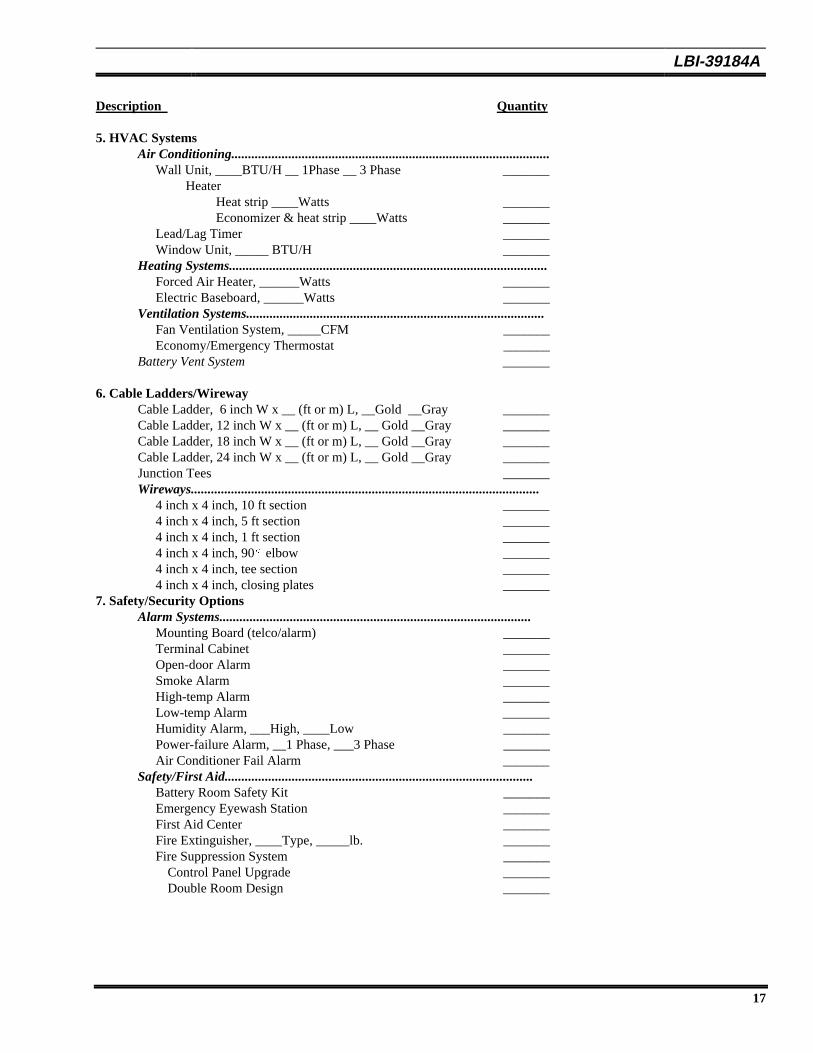
Description Quantity
5. HVAC SystemsAir Conditioning...............................................................................................
Wall Unit, ____BTU/H __ 1Phase __ 3 Phase _______ Heater Heat strip ____Watts _______ Economizer & heat strip ____Watts _______Lead/Lag Timer _______Window Unit, _____ BTU/H _______
Heating Systems...............................................................................................Forced Air Heater, ______Watts _______Electric Baseboard, ______Watts _______
Ventilation Systems.........................................................................................Fan Ventilation System, _____CFM _______Economy/Emergency Thermostat _______
Battery Vent System _______
6. Cable Ladders/WirewayCable Ladder, 6 inch W x __ (ft or m) L, __Gold __Gray _______Cable Ladder, 12 inch W x __ (ft or m) L, __ Gold __Gray _______Cable Ladder, 18 inch W x __ (ft or m) L, __ Gold __Gray _______Cable Ladder, 24 inch W x __ (ft or m) L, __ Gold __Gray _______Junction Tees _______Wireways........................................................................................................
4 inch x 4 inch, 10 ft section _______4 inch x 4 inch, 5 ft section _______4 inch x 4 inch, 1 ft section _______4 inch x 4 inch, 90§ elbow _______4 inch x 4 inch, tee section _______4 inch x 4 inch, closing plates _______
7. Safety/Security OptionsAlarm Systems.............................................................................................
Mounting Board (telco/alarm) _______Terminal Cabinet _______Open-door Alarm _______Smoke Alarm _______High-temp Alarm _______Low-temp Alarm _______Humidity Alarm, ___High, ____Low _______Power-failure Alarm, __1 Phase, ___3 Phase _______Air Conditioner Fail Alarm _______
Safety/First Aid............................................................................................Battery Room Safety Kit _______Emergency Eyewash Station _______First Aid Center _______Fire Extinguisher, ____Type, _____lb. _______Fire Suppression System _______
Control Panel Upgrade _______Double Room Design _______
LBI-39184A
18
Description Quantity
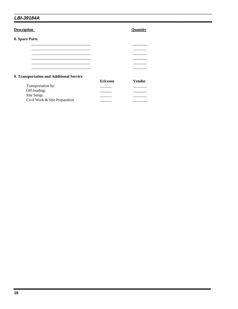
8. Spare Parts______________________________ _____________________________________ _____________________________________ _____________________________________ _____________________________________ _____________________________________ _______
9. Transportation and Additional ServiceEricsson Vendor
Transportation by: ______ _______Off-loading: ______ _______Site Setup: ______ _______Civil Work & Site Preparation ______ _______
LBI-39184A
19
NOTICE !In the next twelve pages that follow are examples ofconcrete buildings configured in sizes 12 X 14 feetthrough 12 X 24 feet. The first six (6) drawings are shownwithout generator room attached. The final six drawingsare configured with the generator room addition.
LBI-39184A
20
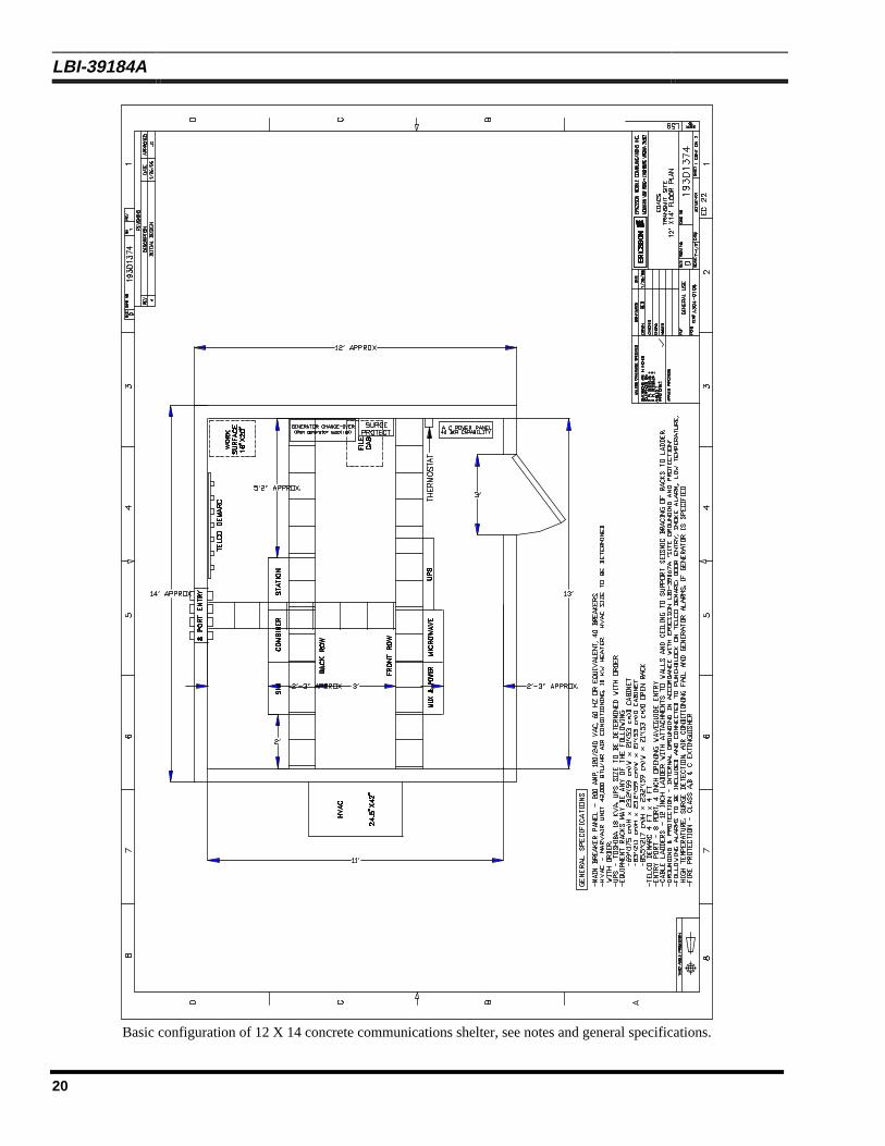
Basic configuration of 12 X 14 concrete communications shelter, see notes and general specifications.
LBI-39184A
21
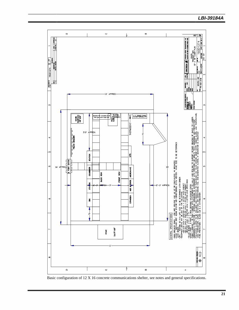
Basic configuration of 12 X 16 concrete communications shelter, see notes and general specifications.
LBI-39184A
22
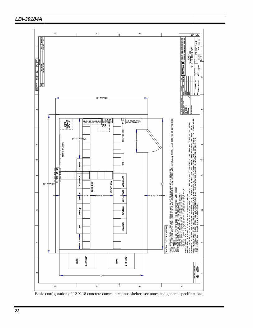
Basic configuration of 12 X 18 concrete communications shelter, see notes and general specifications.
LBI-39184A
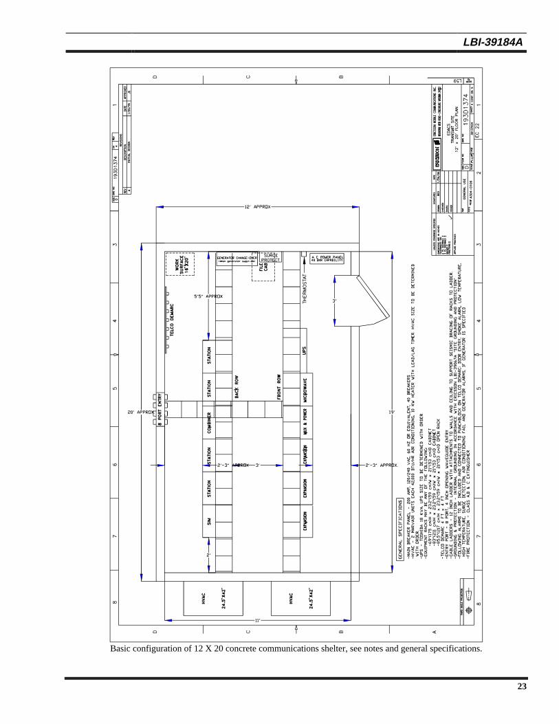
23
Basic configuration of 12 X 20 concrete communications shelter, see notes and general specifications.
LBI-39184A
24
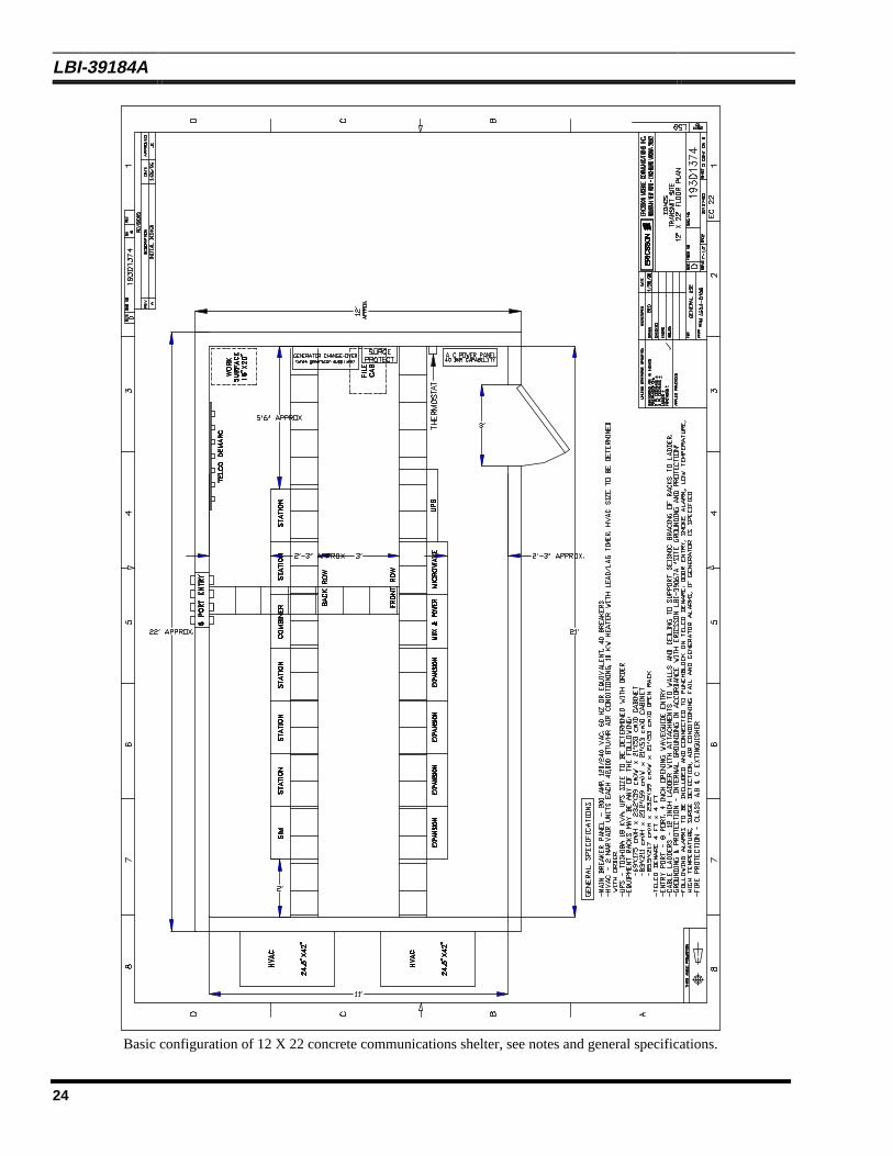
Basic configuration of 12 X 22 concrete communications shelter, see notes and general specifications.
LBI-39184A
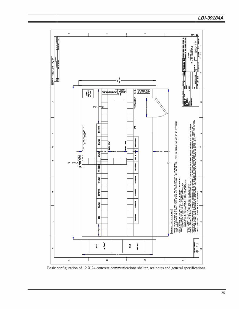
25
Basic configuration of 12 X 24 concrete communications shelter, see notes and general specifications.
LBI-39184A
26
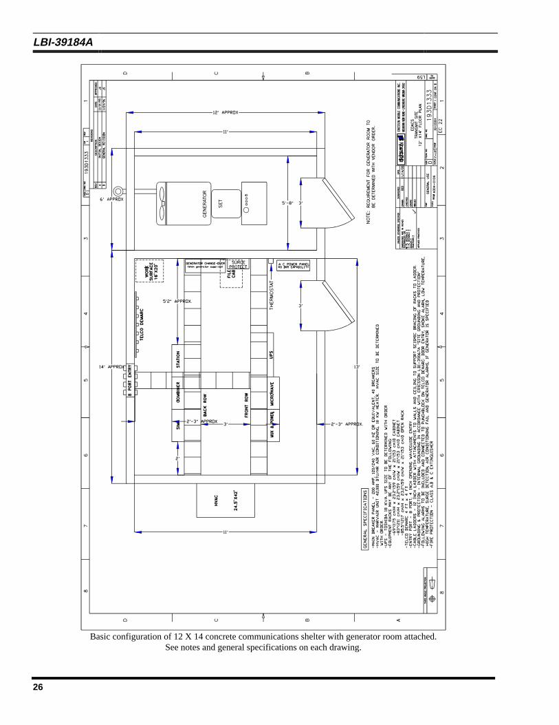
Basic configuration of 12 X 14 concrete communications shelter with generator room attached.See notes and general specifications on each drawing.
LBI-39184A
27
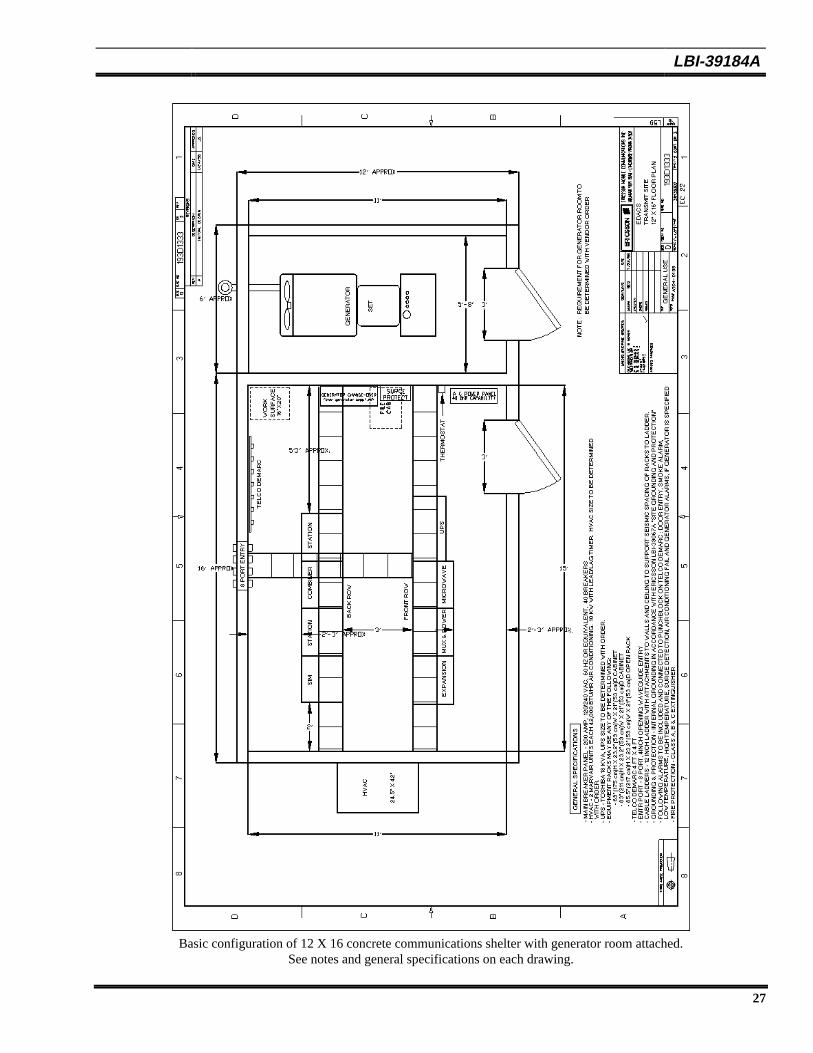
Basic configuration of 12 X 16 concrete communications shelter with generator room attached.See notes and general specifications on each drawing.
LBI-39184A
28
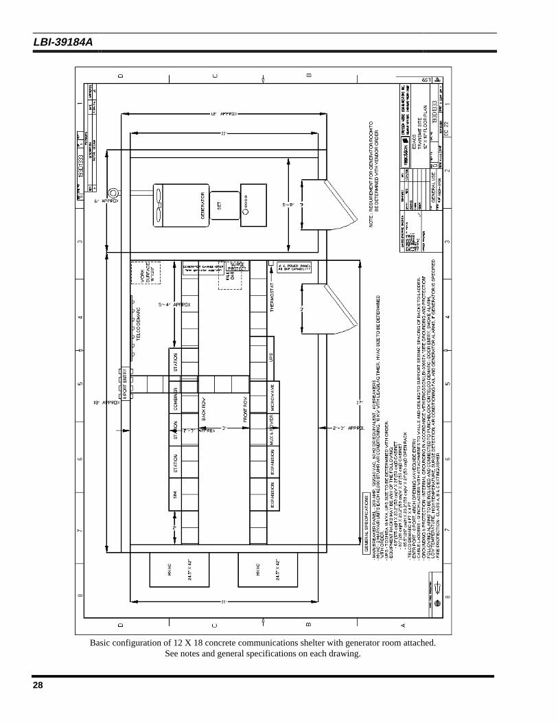
Basic configuration of 12 X 18 concrete communications shelter with generator room attached.See notes and general specifications on each drawing.
LBI-39184A
29
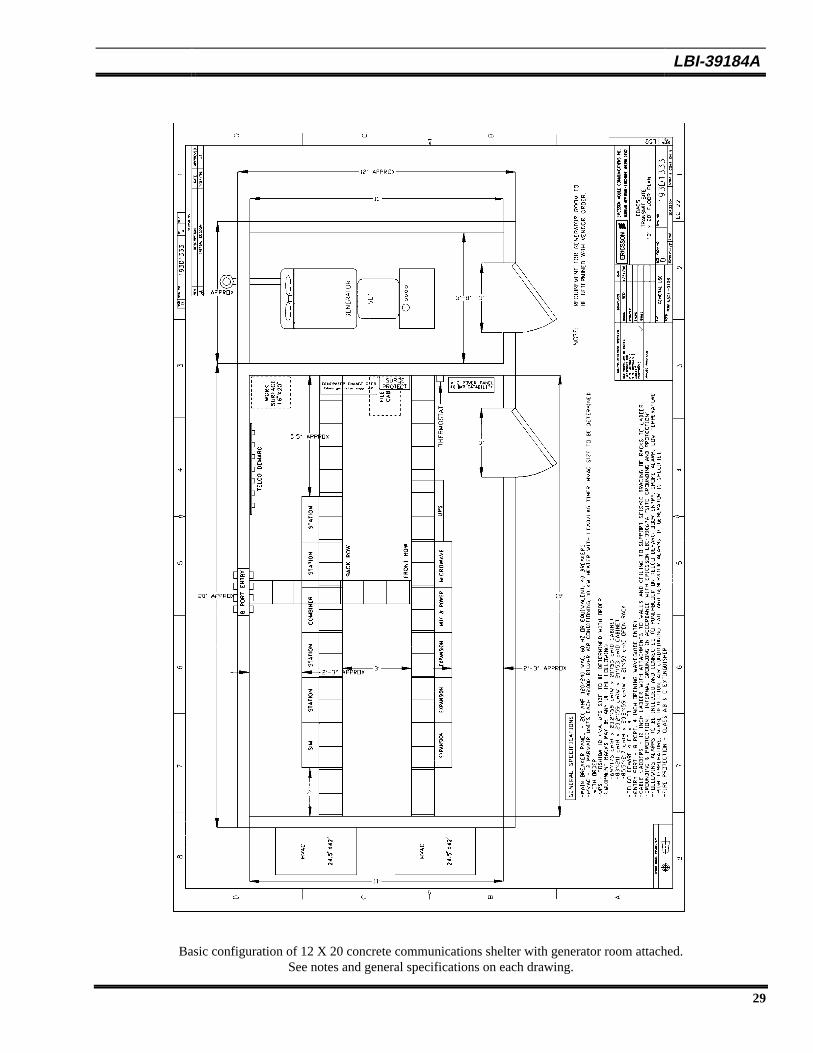
Basic configuration of 12 X 20 concrete communications shelter with generator room attached.See notes and general specifications on each drawing.
LBI-39184A
30
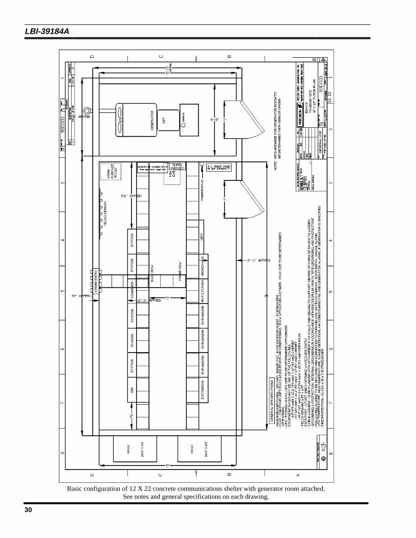
Basic configuration of 12 X 22 concrete communications shelter with generator room attached.See notes and general specifications on each drawing.
LBI-39184A
31
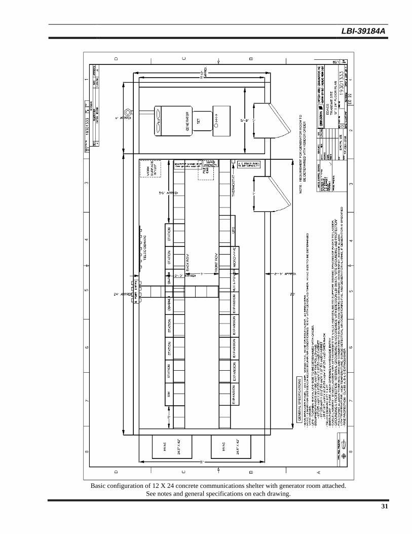
Basic configuration of 12 X 24 concrete communications shelter with generator room attached.See notes and general specifications on each drawing.
LBI-39184A
32
Ericsson Inc.Private Radio SystemsMountain View RoadLynchburg, Virginia 245021-800-528-7711 (Outside USA, 804-528-7711) Printed in U.S.A.